EP2502215B1 - Systems and methods for increasing haptic bandwidth in an electronic device - Google Patents
Systems and methods for increasing haptic bandwidth in an electronic deviceDownload PDFInfo
- Publication number
- EP2502215B1 EP2502215B1EP10787610.4AEP10787610AEP2502215B1EP 2502215 B1EP2502215 B1EP 2502215B1EP 10787610 AEP10787610 AEP 10787610AEP 2502215 B1EP2502215 B1EP 2502215B1
- Authority
- EP
- European Patent Office
- Prior art keywords
- actuator
- processor
- actuators
- haptic
- command signal
- Prior art date
- Legal status (The legal status is an assumption and is not a legal conclusion. Google has not performed a legal analysis and makes no representation as to the accuracy of the status listed.)
- Active
Links
Images


Classifications
- G—PHYSICS
- G06—COMPUTING OR CALCULATING; COUNTING
- G06F—ELECTRIC DIGITAL DATA PROCESSING
- G06F3/00—Input arrangements for transferring data to be processed into a form capable of being handled by the computer; Output arrangements for transferring data from processing unit to output unit, e.g. interface arrangements
- G06F3/01—Input arrangements or combined input and output arrangements for interaction between user and computer
- G06F3/016—Input arrangements with force or tactile feedback as computer generated output to the user
- B—PERFORMING OPERATIONS; TRANSPORTING
- B06—GENERATING OR TRANSMITTING MECHANICAL VIBRATIONS IN GENERAL
- B06B—METHODS OR APPARATUS FOR GENERATING OR TRANSMITTING MECHANICAL VIBRATIONS OF INFRASONIC, SONIC, OR ULTRASONIC FREQUENCY, e.g. FOR PERFORMING MECHANICAL WORK IN GENERAL
- B06B1/00—Methods or apparatus for generating mechanical vibrations of infrasonic, sonic, or ultrasonic frequency
- B06B1/02—Methods or apparatus for generating mechanical vibrations of infrasonic, sonic, or ultrasonic frequency making use of electrical energy
- B06B1/06—Methods or apparatus for generating mechanical vibrations of infrasonic, sonic, or ultrasonic frequency making use of electrical energy operating with piezoelectric effect or with electrostriction
- G—PHYSICS
- G06—COMPUTING OR CALCULATING; COUNTING
- G06F—ELECTRIC DIGITAL DATA PROCESSING
- G06F3/00—Input arrangements for transferring data to be processed into a form capable of being handled by the computer; Output arrangements for transferring data from processing unit to output unit, e.g. interface arrangements
- G06F3/01—Input arrangements or combined input and output arrangements for interaction between user and computer
- G06F3/03—Arrangements for converting the position or the displacement of a member into a coded form
- G06F3/041—Digitisers, e.g. for touch screens or touch pads, characterised by the transducing means
- H—ELECTRICITY
- H02—GENERATION; CONVERSION OR DISTRIBUTION OF ELECTRIC POWER
- H02N—ELECTRIC MACHINES NOT OTHERWISE PROVIDED FOR
- H02N2/00—Electric machines in general using piezoelectric effect, electrostriction or magnetostriction
- H02N2/02—Electric machines in general using piezoelectric effect, electrostriction or magnetostriction producing linear motion, e.g. actuators; Linear positioners ; Linear motors
- H—ELECTRICITY
- H10—SEMICONDUCTOR DEVICES; ELECTRIC SOLID-STATE DEVICES NOT OTHERWISE PROVIDED FOR
- H10N—ELECTRIC SOLID-STATE DEVICES NOT OTHERWISE PROVIDED FOR
- H10N30/00—Piezoelectric or electrostrictive devices
- H10N30/20—Piezoelectric or electrostrictive devices with electrical input and mechanical output, e.g. functioning as actuators or vibrators
- G—PHYSICS
- G06—COMPUTING OR CALCULATING; COUNTING
- G06F—ELECTRIC DIGITAL DATA PROCESSING
- G06F2203/00—Indexing scheme relating to G06F3/00 - G06F3/048
- G06F2203/01—Indexing scheme relating to G06F3/01
- G06F2203/014—Force feedback applied to GUI
Definitions
- the present disclosurerelates generally to systems and methods for increasing haptic bandwidth in an electronic device.
- a controllermay send signals to one or more driver circuits for directing operation of the actuators.
- the controllermay provide direction and amplitude control, vibration control, and frequency control to direct the haptic experience.
- Parameterssuch as frequency, phase, amplitude, duration, and direction can be programmed or input as different patterns suitable for use in gaming, virtual reality and real-world situations.
- Input parameters of amplitude, phase and position for a pair of linear actuatorsmay be used to vary force effects and control the direction of vibration.
- WO 2007/117418 A2relates to a handheld gaming machine including one or more actuators for providing vibrational cues or feedback during play of a wagering game to indicate the occurrence of a wagering- game event, such as a change in game rules, an input of a wager, and the like.
- the positioning of two actuatorscreates a "stereo haptic" effect, which can be actuated independently to create vibrational cues and feedback that are sensed by different parts of the player's body, for example the left and right hands or by the left and right thighs of a player's lap.
- the actuatorscan be vibrated according to respective vibrating profiles.
- Embodiments of the present inventionprovide systems and methods for increasing haptic bandwidth in an electronic device.
- the present inventionprovides an apparatus as defined in claim 1.
- the present inventioncorrespondingly provides a method as defined in claim 12 and a computer readable medium as defined in claim 15. Further optional features of the invention are defined in the dependent claims.
- Example embodimentsare described herein in the context of systems and methods for increasing haptic bandwidth in an electronic device. Those of ordinary skill in the art will realize that the following description is illustrative only and is not intended to be in any way limiting. Other embodiments will readily suggest themselves to such skilled persons having the benefit of this disclosure. Reference will now be made in detail to implementations of example embodiments as illustrated in the accompanying drawings. The same reference indicators will be used throughout the drawings and the following description to refer to the same or like items.
- Figure 1shows a system 50 for increasing haptic bandwidth in an electronic device according to one illustrative embodiment of the present invention.
- a cell phone 60comprises a touch screen 66 and several actuators 70-76 for outputting various haptic effects to the cell phone 60.
- two of the actuators 70, 72are piezo-electric actuators and the other two actuators 74, 76 are rotary motors having an eccentric rotating mass (commonly referred to as an "ERM").
- the cell phone 60also includes a processor 62, a memory 64, a sensor 68.
- the processor 62executes software stored in memory 64 and displays graphical user interface (GUI) elements on the touch screen 66.
- GUIgraphical user interface
- a userinteracts with the cell phone 60 by touching the touch screen 66 to select one or more GUI elements or by making gestures on the touch screen 66.
- the sensor 68detects the various contacts with the touch screen 66 and provides sensor signals to the processor 62, which interprets the signals based on the position of GUI elements displayed on the touch screen 66 and any detected gestures.
- the processor 62may determine that one or more haptic effects are to be output to the cell phone 60 based on user inputs or on events occurring within the GUI or other applications executed by the processor 62, such as text messaging software. After determining one or more haptic effects to be output, the processor 62 selects one or more actuators 70-76 to use to output the haptic effects.
- memory 64stores parametric information about each of the actuators, including frequency ranges, resonant frequencies, startup and stop times, power consumption, or physical coupling information, such as whether the actuator is coupled to the housing of the cell phone 60, the touch screen 66, or other parts of the cell phone 60, such as physical keys or buttons (not shown). Based on the actuator information, the processor 62 generates actuator signals for the haptic effects, selects the actuator or actuators to output the haptic effects, and transmits the actuator signals to the actuator(s) at the appropriate times to generate the desired haptic effects.
- each key "pressed" by the usermay result in a haptic effect.
- the processor 62determines that sharp, high-frequency haptic effects are needed for each key press.
- the processor 62determines that the ERM actuators 74, 76 should be used to output the haptic effects.
- the processor 62determines that the ERM actuators 74, 76 are capable of generating high-magnitude forces and are coupled to the housing of the cell phone 60 based on stored actuator profiles for each of the actuators 70-76.
- both ERM actuators 74, 76should be used and should be alternated because the startup and stop characteristics of the ERM actuators 74, 76 may take too long to fully stop a haptic effect before the next haptic effect is to be output, i.e. the individual ERM actuators 74, 76 may have insufficient bandwidth to support haptic effects that occur as rapidly as keystrokes.
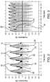
- One way of defining the bandwidth of a vibrating motor actuatoris the maximum frequency that can be obtained between from an actuator before the pulses output by the actuator begin to feel as mushy, continuous vibration.
- the pulses 10are generated by a single vibrating actuator in response to a non-continuous or pulsed signal 20, whereby the pulsed signal 20 is approximately at 5 Hz.
- the response or deceleration output by the actuatoris such that the actuator is able to vibrate for some time and come to an almost complete stop (Point A) before it is instructed to accelerate again.
- Figure 3illustrates the same actuator in which the pulsing signal is at a frequency of 10 Hz.
- the magnitude of pulse vibrations 30 output by the actuatoris not able to approach a zero value before the pulsing signal 40 instructs it to begin accelerating again (see Point B in Figure 2 ).
- the actuatoris unable to decelerate to a magnitude where the magnitude of the haptic effect cannot be felt before the actuator begins to accelerate toward the maximum magnitude again.
- Thiscan lead to "mushy" haptic effects where each effect tends to be hard to distinguish from the next, which tends to degrade the user's experience.
- the illustrative system in Figure 1employs multiple actuators and novel methods of actuating those actuators.
- the processormay determine that additional haptic effects are needed. For example, when the user presses the "send" button, the processor 62 determines that a haptic effect should be output to indicate that the send button was pressed. In this illustrative embodiment, the processor 62 determines that a texture haptic effect should be output in addition to a vibration effect. In such an embodiment, the processor 62 generates the vibration effects by sending signals alternately to one ERM actuator 74 and then the other ERM actuator 76, as will be described in greater detail below.
- the processor 62generates actuator signals with high frequencies (e.g. >20kHz) and determines that the ERM actuators are already in use, that the ERM actuators are not suitable for generating such high frequencies, and that the piezoelectric actuators 70, 72 are capable of generating the necessary frequencies. Further, the processor 62 determines, based on the stored actuator parameter information, that each piezoelectric actuator 70, 72 is configured to output a haptic effect in only one dimension and that the two piezoelectric actuators 70, 72 are oriented along orthogonal axes. Therefore, in this embodiment, the processor 62 determines that each of the piezoelectric actuators 70, 72 should be actuated to generate the texture effect. Thus, the processor 62 transmits high-frequency actuator signals to each of the piezoelectric actuators 70, 72 to generate a haptic effect to simulate a textured surface on the touch screen 66.
- high frequenciese.g. >20kHz
- Such an illustrative embodimentprovides increased haptic bandwidth by selectively actuating actuators 70-76 based on performance characteristics of the actuators stored within the cell phone's memory 64. Further, because a plurality of different actuators are provided, multiple effects may be output (or played) simultaneously, or may be output with high fidelity despite insufficient performance characteristics of one or more of the actuators 70-76 for the haptic effects to be output. For example, high-magnitude precise vibrations can be output a rate greater than the peak bandwidth of one of the ERM actuators 74, 76 by outputting the vibrations alternately between the two ERM actuators 74, 76.
- Figure 4illustrates a block diagram of an electronic device in accordance with an embodiment.
- Figure 4illustrates an electronic device 100 having a body or housing 102, a processor 104 within the body 102 and coupled to a memory 106.
- the processor 104is able to store information to and retrieve information from the memory 106.
- Such informationmay include, but is not limited to, actuator profiles, haptic effect profiles, haptic effect output time sequences, programmed voltages to send to the actuators, game data, software data, etc.
- the electronic device 100is shown with one or more optional touch screens, touch pads or other touch sensitive components 108 coupled to the processor 104. It should be noted that some embodiments of the present invention may not include a touch sensitive component 108. For instance, some embodiments of the present invention may be applied to other types of devices, such as a joystick, rotatable knob, stand-alone kiosk, computer mouse, virtual reality simulation, computer peripheral, smart phone, handheld computer, game peripheral, etc. However, for explanation purposes, the touch sensitive component 108 will be used to describe embodiments of systems and methods for increasing haptic bandwidth in an electronic device.
- the device 100includes a sensor 110 coupled to the touch screen 108 and processor 104, whereby the sensor 110 monitors the position, pressure, and/or movement of the user's finger(s), stylus or other input means during interaction with the touch sensitive component 108.
- the sensor 110provides sensor signals to the processor 104 to indicate the pressure, position and/or movement of the user's input, whereby the processor 104 running the software program updates the display shown through the touch sensitive component 108 in response thereto.
- the touch sensitive component 108incorporates the sensor 110 therein as an integral component, and thus the sensor 110 is not a separate component. However, for purposes of discussion, the sensor 110 is referred to herein as a separate component.
- the electronic device 100includes a plurality of actuators 112, 114, 116 within the body. It should be noted that although three actuators are shown in Figure 4 , as little as two actuators are contemplated or more than three actuators are also contemplated.
- the actuators 112, 114, 116are all mounted to the body 102 of the device 100 to impart a haptic effect thereto.
- one or more of the actuatorsare mounted to the touch sensitive component 108 or other respective user input device to impart a localized haptic effect thereto. It is contemplated that one or more of the actuators may be mounted to the touch sensitive component 108 or other respective user input device while the remaining actuators are mounted to the body 102 or to one or more physical buttons (not shown).
- At least one actuatoris suspended within the body 102 and may be configured to impart haptic effects to the touch sensitive component and/or the body 102.
- the actuatormay be designed to utilize a flexible or resilient material to amplify haptic effects produced therefrom.
- one or more actuatorsare part of an external device or peripheral that is externally mounted to the body 102 to output haptic effects thereto.
- the actuators 112-116are configured to output one or more haptic effects upon receiving an input command signal from the processor 104.
- the input command signalmay be from an interaction which may occur between the user and a graphical object within a graphical environment run by a software program, whereby the software program may be run on the local processor or a host computer separate from the electronic device.
- the interactionmay also be user independent in which the user's action does not cause the interaction (e.g. text message received, asteroid hitting the user's vehicle in a game).
- the interactionmay, however, cause a haptic event to occur or may be the product of the user selecting a haptic area, both of which are discussed in more detail below.
- actuatorscan be of various types including, but not limited to, eccentric rotational mass (ERM) actuators, linear resonant actuators (LRA), piezoelectric actuator, voice coil actuator, electro-active polymer (EAP) actuators, memory shape alloys, pager or DC motors, AC motors, moving magnet actuators, E-core actuators, smartgels, electrostatic actuators, electrotactile actuators, etc.
- ECMeccentric rotational mass
- LRAlinear resonant actuator
- EAPelectro-active polymer
- memory shape alloyspager or DC motors
- AC motorsAC motors
- moving magnet actuatorsmoving magnet actuators
- E-core actuatorssmartgels
- electrostatic actuatorselectrotactile actuators, etc.
- the actuators 112-116output their respective haptic effects in response to one or more haptic events occurring in the graphical environment.
- the haptic eventis referred to herein as any interaction, action, collision, or other event which occurs during operation of the device which can potentially have a haptic effect associated with it, which is then output to the user in the form of the haptic effect.
- a haptic eventmay occur when a graphical vehicle the user is controlling experiences wind turbulence during game play, whereby an example haptic effect associated with that haptic event could be a vibration.
- a haptic eventmay occur when a missile collides with the user's character in the game, whereby an example haptic effect associated with the haptic event is a jolt or pulse.
- Haptic eventsmay not be associated with the game play, but nonetheless provides the user with important device information while the user is playing a game (e.g. receiving a text message, completion of a song download, battery level low, etc.).
- the interactionmay correlate with a graphical object of a graphical environment which the user interacts with on a display screen.
- a haptic effectmay be output by the system in response to an interaction where the user selects a designated area in a graphical environment, hereby referred to as a displayed haptic enabled area or just "haptic area.”
- a displayed haptic enabled areahereby referred to as a displayed haptic enabled area or just "haptic area.”
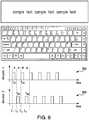
- the boundaries of a displayed key of a keyboardmay each be designated a haptic area.
- the left boundary 202, right boundary 204, bottom boundary 206 and top boundary 208 of "shift" keymay each be designated a haptic area, whereby the processor 104 instructs the actuators to output respective haptic effects when the sensor 110 indicates that the user's finger or stylus is moving over one or more of displayed boundary or boundaries. It is also contemplated that the area between the boundaries 202-208 within the "shift" key may be designated a haptic area. In some embodiments, haptic areas are designated when developing the software that is to be run on the device 100. In some embodiments, however, a user may be able to customize existing haptic areas or develop/designate new ones such as via a Preferences or Options menu.
- the present system and methodutilizes multiple actuators to operate in successive order for a duration of time during which the interaction occurs.
- the staggered output of the multiple actuatorsare to increase the output bandwidth of the actuators at faster intervals and produce distinct, discrete haptic effects which are discernable to the user.
- the processor 104applies an input command signal with a designated voltage and current to the actuator 112 at a start time to cause the actuator 112 to accelerate to a maximum designated magnitude to output a corresponding haptic effect.
- the processor 104terminates the input command signal at a stop time (such as based on programmed parameters of the hap tic effect which are stored in memory), upon which the actuator 112 decelerates from the maximum magnitude to a stop.
- the processor 104then applies a designated voltage and current to the second actuator 114 at a respective start time to cause the actuator 114 to accelerate to a maximum designated magnitude to output a corresponding haptic effect.
- the processor 104terminates the pulse signal to the actuator 114 to allow the second actuator 114 to decelerate from its maximum magnitude to a stop.
- the processor 104then again sends the input command signal to the first actuator 112 to begin outputting a haptic effect and so on.
- this processis repeated between the actuators 112, 114 to thus cause the actuators 112, 114 to alternately and successively output their respective haptic effects.
- a particular actuatordoes not begin operating until the haptic effect output by the other actuator is at least at a magnitude and/or frequency that is not able to be discernibly felt by the user. However, in some embodiments, a particular actuator does not begin operating until the haptic effect output by the other actuator is at a zero magnitude and/or frequency.
- the scheduling of the start and stop times of the input command signals toward each of the actuatorsare predetermined and stored in the memory. This allows the processor to quickly retrieve the scheduling data and thus ease computational burdens when a haptic effect is to be output.
- the stored scheduling informationmay be in the form of a lookup table or other stored configuration in which the start and stop times for each actuator, in relation to the other actuators, are already established in which the processor 104 merely processes the stored information and accordingly activates the actuators based on the designated scheduling instructions.
- the scheduling instructionsmay be based on the type of actuators used (e.g.
- ERMERM, LRA, piezoelectric, etc.
- desired maximum and minimum magnitudes to be output by the actuatorsvoltages and frequencies at which the actuators will operate, type of haptic effect to be output (e.g. vibration, pop, click, etc.), and the overall operating characteristics of the actuators (e.g. heavy or light actuators, etc.).
- the particular operating characteristics of the actuator 112will be known to the processor 104 in which the processor 104 is provided information on how long it takes the actuator 112 to accelerate from a stopped position to the desired magnitude and frequency based on the applied voltage and current.
- the memory 106may store information regarding how long it takes for the actuator 112 to decelerate from its maximum operating magnitude and frequency back to the stopped position. This is because, in one embodiment, the acceleration and deceleration time of the actuator 112, based on the type of current (i.e. AC vs. DC), is already known and is stored in the memory 106 as data or an instruction to be read by the processor and accordingly provided to the actuators.
- memory 106comprises one or more actuator profiles associated with the actuators 112-116.
- the actuator profilescomprise a plurality of parameters associated with the actuators, such as start-up time, stop time, minimum and maximum frequencies, maximum magnitudes, resonant frequencies, haptic effect types, axis(es) of operation, or power consumption.
- the processor 104may then access the actuator profiles to determine which actuators, and how many actuators, to employ to generate one or more haptic effects.
- Figure 6illustrates a graph illustrating the scheduled haptic effects output by two actuators in the system in accordance with an embodiment.
- the top graph 300illustrates the pulsed haptic effect output by the first actuator 112
- the bottom graph 400illustrates the pulsed haptic effect output by the second actuator 114 in which both graphs share a common time line.
- the processor 104upon a haptic event occurring or haptic area being determined, the processor 104 sends its command signal to the actuator 112 at time t 1 in which the actuator 112 begins its operation.
- the input command signalis a square wave signal in which the processor 104 terminates its command signal at time t A1 , whereby time t A1 occurs before t 2 .
- the processordetermines time t A1 based on actuator parameters stored in memory. For example, in one embodiment, the processor 104 determines a percentage of the stop time for an actuator 112, 114 to determine a minimum amount of time to wait after an actuator signal has been terminated before a new signal may be begun.
- the processor 104determines an amount of time to wait after an actuator signal has been terminated before beginning a haptic effect of the same type.
- a devicemay comprise multiple different types of actuators, such as ERM actuators, DC motors, piezoelectric actuators, LRAs, etc.
- a processormay simultaneously actuate multiple actuators to output different types of effects, such as textures, vibrations, and torques.
- a processormay cause texture effects to be output irrespective of the status of vibrational effects or torsional effects.
- the processor 104may determine that no wait time is required as a first haptic effect may be output substantially simultaneously as a second haptic effect without interfering with the two effects.
- the actuator 112decelerates to a magnitude such that no discernable haptic effect is felt by the user. In an embodiment, the actuator 112 decelerates to a zero magnitude around time t A1 .
- different input command signals or actuator signalsmay be employed other than square waves.
- actuators signalsmay be generated to accelerate or decelerate actuators to provide high-fidelity haptic effects such as is disclosed in U.S. Patent No. 7,639,232, filed November 30, 2005 , entitled "Systems and Methods for Controlling a Resonant Device for Generating Vibrotactile Haptic Effects".
- the processor 104sends an input command signal to the actuator 114 in which the actuator 114 begins its operation and accelerates to a maximum magnitude.
- the command signalis a square wave signal in which the processor 104 terminates its command signal at time t B1 , whereby time t B1 occurs before t 3 .
- the actuator 114has sufficiently decelerated so that the processor 104 determines that the next actuator may be actuated. For example, in this embodiment, the processor 104 determines a portion of the stop time stored as a parameter for actuator 114 in memory. In an embodiment, the actuator 114 comes to or near a complete stop around time t B1 .
- the processor 104delays a fixed amount of time before actuating the next actuator 112. Thereafter, the processor 104 then instructs actuator 112 to begin operation at time t 3 and so on.
- This alternating pattern of output from multiple actuatorscan generate discrete haptic effects which are distinct and discernable when felt by the user, because the actuators are scheduled to operate in a staggered manner to provide the user with the feeling that the pulse from a prior haptic effect has sufficiently degenerated before a subsequent pulse is felt.
- a single actuatormay not be able to achieve this result at frequencies around or greater than 10 Hz, the scheduling of multiple actuators is able to achieve such a result as such higher frequencies.
- a QWERTY keyboardhas keys approximately 6 millimeters wide in which the processor 104 instructs a single actuator to output a haptic effect upon the sensor 110 indicating that the user's finger (or stylus) is positioned on one boundary of a particular key.
- the user's fingerruns across a series of keys (in particular, keys “z” to "m") at a rate of 7 keys per second.
- the actuatorsare required to output haptic effects on the order of 1 key boundary every 70ms, which translates into approximately 14 key boundaries every second (or 71.4 milliseconds per boundary).
- a single actuator tasked to output a vibration for each of the haptic areasmay generate a continuous, or nearly continuous, vibration, and thus the user may not feel any distinction between key boundaries. This is because the single actuator does not have the time to stop completely before the next pulse is already being output.
- multiple actuatorsare employed to successively output the haptic effects to provide this tactile information.
- the processor 104applies a first command signal to the actuator 112
- the processor 104applies a second command signal to actuator 114.
- the processor 104applies a third command signal to actuator 112. This alternating pattern between the multiple actuators 112, 114 produces definitive and distinct haptic effects which are able to be distinguished by the user.
- a single actuator(such as actuator 112) may be used to output multiple haptic effects when the amount of time between triggering haptic events and/or haptic areas is longer than the amount of time needed for the actuator to come to a complete stop or at least decelerate to a magnitude that is not able to be felt to the user.
- the processor 104activates multiple actuators (e.g. 2, 3, or more) successively when the amount of time between triggering haptic events and/or haptic areas is less than the amount of time needed for the actuator to come to a complete stop or at least decelerate to a magnitude that is not able to be felt to the user.
- the amount of time neededis based on the operating parameters and type of actuators used as well as the amount of current and voltage applied to the actuators.
- the haptic effects that can be produced by the actuatorsvary depending on the current, voltage, frequency as well as start and stop times. Such haptic effects include, but are not limited to, vibrations, pulses, pops, clicks, damping characteristics, and varying textures.
- the multiple actuatorsare utilized to generate different haptic effects for different applications.
- the two actuatorsare configured to provide a vibration or pop upon the user's finger or stylus passing over the boundaries of a graphical object (e.g. keyboard keys), as discussed above.
- one or more actuators coupled to the touch sensitive componentare activated when the user is detected within the boundaries to generate a texture-like haptic effect.
- the actuatoris an eccentric rotating mass (ERM) actuator which is driven using a continuous DC voltage, whereby the ERM actuator is pulsed by the processor 104 to output the haptic effect and also achieve relatively short start and stop times at lower frequencies.
- ERMeccentric rotating mass
- the ERM actuator's responseespecially the ability to accelerate and decelerate quickly enough to the desired magnitude, may be slower than needed to produce the distinct haptic effects described above.
- the response of the actuatorwill be at a predetermined magnitude and frequency. In other words, increasing the magnitude of the DC driving voltage will proportionally result in an acceleration response with higher magnitude and higher acceleration. In the same vein, decreasing the magnitude of the DC driving voltage will proportionally result in a deceleration response with a lower magnitude and a lower deceleration.
- an ERM actuatormay not be able to generate vibrations that are clear and distinct and having a magnitude of 0.4 Gpp at 120Hz upon the processor applying only a DC voltage to the actuator.
- the processor 104applies an AC signal to the actuator, whereby the actuator responds to the driving signal with an acceleration profile having the same frequency content as the input signal.
- This technique of overdriving the actuators in an AC (bipolar) modedramatically improves the bandwidth of the actuator in the frequency domain. The actuator is thus able to generate different vibration effects at specific magnitudes and accelerations by superimposing the AC and DC input signals.
- the main advantage of using multiple actuators in AC modeis that the overall system can achieve the principle of superposition. Applying two different input signals to the actuators, in which each input signal has different frequencies and magnitude parameters, will result in a vibration effect having those frequencies and proportional magnitudes.
- a single actuatoris not capable of generating this superposition effect because it was not meant originally to have such a high bandwidth as was obtained when driving it in AC mode.
- This superposition principleis important when generating high fidelity vibration feedback (textures, pops and vibrations at the same time).
- the actuators described aboveare ERM actuators
- the actuatorsmay also be a linear resonant actuator (LRA).
- LRA actuatoris a DC motor with a resonant mass-spring system in which the mass is actuated linearly back and forth in a one dimensional direction.
- the deviceis capable of generating a high acceleration response at a specific frequency, for instance 175Hz. However, at other frequencies the acceleration is close to 0 for the same input magnitude. However, if the magnitude of the input signal is increased in those areas where the response is weak, the resulting acceleration is strong enough to provide a good vibration effect at those specific frequencies and with a magnitude dependent on the magnitude of the driving signal.
- other types of actuatorsmay be employed.
- smart gel actuatorsmay be employed to provide textures or physical boundaries on the touch screen that correspond to objects shown by the touch screen, such as keys on a keyboard.
- actuators 112-116may comprise ERM or LRA actuators and piezoelectric actuators.
- piezoelectric actuatorsmay provide different types of haptic effects than ERM or LRA actuators.
- piezoelectric actuatorsmay provide low magnitude effects, but may have wide frequency ranges in which effects may be output.
- piezoelectric actuatorsmay be well-suited to applying haptic effects to a touch screen.
- memory 106may comprise parameters associated with each of the actuators 112-116.
- memory 106comprises parametric information about each of the actuators, such as minimum and maximum operational frequencies, minimum and maximum operational magnitudes, start-up and stop times, and axis(es) of operation.
- the ERM actuatorshave minimum and maximum operational frequencies of approximately 100 and 300 Hz respectively, while the piezoelectric actuators have minimum and maximum operational frequencies from 100 to 25,000 Hz.
- the processor 104determines a vibrational haptic effect is to be output at approximately 200Hz and generates a first actuator signal configured to cause a vibration at 200 Hz. Based at least in part on the actuator parameter information, the processor selects one of the ERM actuators. The processor then transmits the first actuator signal to the selected ERM actuator. The processor also determines that a texture haptic effect is to be output at approximately 25,000 Hz and generates a second actuator signal configured to cause a vibration at 25,000 Hz. Based at least in part on the actuator parameter information, the processor selects one of the piezoelectric actuators. The processor then transmits the second actuator signal to the selected piezoelectric actuator. In this embodiment, the two haptic effects may be output at approximately the same time. Thus, the actuator sequencing described above need not be performed. However, if multiple haptic effects are to be output in rapid succession, the processor 104 may output the first actuator signal alternately to the two ERM actuators according to embodiments of the present invention.
- ERM and piezoelectric actuatorsother combinations of actuators may be used.
- a combination of ERM and LRA actuatorsmay be used.
- multiple ERM or LRA actuators of different sizesmay be included to provide a range of vibrational frequencies, which may be actuated individually or simultaneously.
- memory 106comprises parameters associated with each actuator, including minimum and maximum operational frequencies, minimum and maximum operational magnitudes, start-up and stop times, and axis(es) of operation.
- the parametersalso further comprise a resonant frequency associated with each actuator, if the respective actuator has such a characteristic.
- the processor 104may select a suitable actuator or actuators to generate the desired haptic effects.
- the processor 104selects the appropriate actuator or actuators based upon the haptic effect to be output and the parameters describing each of the actuators. In some embodiments, the processor 104 may further select an actuator based on the operational status of an actuator, such as whether the actuator is in use or is still stopping.
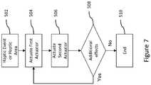
- Figure 7illustrates a flow chart directed to the method of outputting haptic effects to increase the haptic bandwidth of the actuators in an electronic device.
- the processoris provided with information as to whether a haptic event occurs (e.g. a collision in a video game) and/or a haptic area has been selected (e.g. user's finger or stylus moving over a boundary of a displayed key). This information may be provided from the sensor 110 and/or from the software running by the processor or a separate host computer.
- the processor 104Upon the processor 104 being notified that a haptic effect is to be output, the processor 104 applies an input command signal to the first actuator at predetermined start and stop times, as in 504.
- the processorapplies an input command signal to the second actuator at predetermined start and stop times, as in 506, whereby the start time of the second actuator does not occur until after the stop time of the input command signal to the first actuator.
- this processrepeats between the first and second actuators 112, 114 for a predetermined duration of time, as in 506.
- the processor 104confirms that the haptic event and/or haptic area is still activated, or in other words that the interaction is still occurring, when the predetermined duration of time has expired, as in 508. If the interaction which is causing the haptic effect is still occurring when the duration expires, the processor 104 continues to alternate between the actuators, as in 504. On the other hand, if the interaction is over when the duration ends, the processor 104 terminates the input command signal to the actuators, 510. It is contemplated that the processor 104 is informed if the interaction ceases prior to the expiration of the duration, whereby the processor 104 will prematurely terminate the input command signal to the actuators to end the outputted haptic effects.
- Figure 8illustrates another flow chart directed to the method of outputting haptic effects to increase the haptic bandwidth of the actuators in an electronic device.
- the processordetermines whether the two or more distinct haptic effects are to be output as a result of the action requiring the haptic effect, as shown as 602. If it is determined that less than two distinct haptic effects are to be produced, the processor 104 instructs only a single actuator to output the haptic effect, as in 604 in Figure 8 . Again, this determination may be based on the sensor information and/or software instruction as well as the assigned haptic effect for the particular action.
- a collisionmay occur on the display in which the designated haptic effect for the collision is a single vibration, whereby the processor 104 would instruct only one actuator to output the vibration.
- the processor 104would instruct only one actuator to output the vibration.
- 604is optional as the processor may alternatively choose to have more than one actuator simultaneously, or in sequence, output the haptic effect.
- haptic event/haptic areait is determined whether the multiple actuators would be operating at a frequency and magnitude such that haptic effects would not be distinct and individually discernible to the user if only a single actuator were employed, as shown as 606 in Figure 8 , or whether the two (or more) haptic effects are of different types such that different types of actuators should be used (e.g. ERM and piezoelectric).
- the processor 104would then send input command signals to multiple actuators, as in 608, whereby the command signals would selectively activate the actuators in an alternating manner, such as according to the embodiment shown in Figure 7 , to output clear, distinct, and discernible haptic effects from the actuators.
- the processor 104determines that the multiple haptic effects could be output by a single actuator based on the parameters describing the actuator and characteristics of the haptic effects. In some embodiments, the processor 104 makes these determinations in real-time. However, in some embodiments, each of the assigned haptic effects, along with frequency, magnitude, start and stop time data, other parameters of the actuators and instructions on whether single or multiple actuators are to be output are stored in the memory 106 such that the processor 104 can easily processes the instructions and accordingly instruct which actuators to activate.
- this determinationmay be based on the sensor information, actuator parameters stored in memory 106, and/or software instruction as well as the assigned haptic effect for the particular action. For example, a collision may occur on the display in which the designated haptic effect for the collision is a single vibration, whereby the processor 104 would instruct only one actuator to output the vibration.
- the processor 104determines that multiple haptic effects are to be output by multiple actuators based on the type of haptic effects to be output. For example, at step 600, the processor 104 determines that a vibrational haptic effect is to be output based on a user contacting the edge of a key on a virtual keyboard and that a textured haptic effect should be output to simulate the feel of a keyboard. In such an embodiment, at step 602, the processor 104 determines that multiple haptic effects are to be output and the method proceeds to step 606.
- a texture effectmay be output by a outputting a vibration at a frequency of greater than approximately 20kHz and adjusting the magnitude of the vibration, such as by setting the magnitude of vibration as a percentage of the maximum magnitude or by modulating the magnitude according to a second signal, such as a sine wave or other periodic or non-periodic waveform.
- the magnitude of the vibrationmay be set to 0% outside of a haptic region and to 50% or 100% for contact within the haptic region.
- a second or modulating frequencymay have a frequency of 10Hz such that the magnitude of the 20kHz vibration varies from 0 to 100% at a rate of 10Hz. In some embodiments, higher modulating frequencies may be used, such as 100Hz, 500Hz or 1000Hz, or other suitable frequencies.
- the processor 104analyzes parameters stored in memory 106 that are associated with each actuator. Based on the parameters, the processor 104 determines that the ERM actuators are not capable of producing such effects. Therefore the processor 104 determines that a piezoelectric actuator should be selected to output the texture effect.
- a vibration to indicate the edge of a key on a virtual keyboardmay have a high-magnitude vibration frequency between approximately 100-300Hz, such as 200Hz.
- the processor 104selects an ERM actuator to output the haptic effects.
- the processor 104may further determine that multiple vibrational effects are to be output and that multiple ERM actuators should be employed, such as by employing techniques described above. After determining which actuators are associated with each haptic effect, the method proceeds to step 608.
- the processorIn step 608, the processor generates a first actuator signal configured to cause a vibration at a frequency of greater than approximately 20kHz to generate the texture haptic effect.
- the processoralso generates a second actuator signal configured to cause a vibration at 200Hz.
- the processorthen transmits the first actuator signal to the piezoelectric actuator and transmits the second actuator signal to the ERM actuator.
- the processor 104may alternately transmit the second actuator signal to multiple ERM actuators as described above.
- a computermay comprise a processor or processors.
- the processorcomprises a computer-readable medium, such as a random access memory (RAM) coupled to the processor.
- the processorexecutes computer-executable program instructions stored in memory, such as executing one or more computer programs for editing an image.
- Such processorsmay comprise a microprocessor, a digital signal processor (DSP), an application-specific integrated circuit (ASIC), field programmable gate arrays (FPGAs), and state machines.
- Such processorsmay further comprise programmable electronic devices such as PLCs, programmable interrupt controllers (PICs), programmable logic devices (PLDs), programmable read-only memories (PROMs), electronically programmable read-only memories (EPROMs or EEPROMs), or other similar devices.
- Such processorsmay comprise, or may be in communication with, media, for example computer-readable media, that may store instructions that, when executed by the processor, can cause the processor to perform the steps described herein as carried out, or assisted, by a processor.
- Embodiments of computer-readable mediamay comprise, but are not limited to, an electronic, optical, magnetic, or other storage device capable of providing a processor, such as the processor in a web server, with computer-readable instructions.
- Other examples of mediacomprise, but are not limited to, a floppy disk, CD-ROM, magnetic disk, memory chip, ROM, RAM, ASIC, configured processor, all optical media, all magnetic tape or other magnetic media, or any other medium from which a computer processor can read.
- the processor, and the processing, describedmay be in one or more structures, and may be dispersed through one or more structures.
- the processormay comprise code for carrying out one or more of the methods (or parts of methods) described herein.
Landscapes
- Engineering & Computer Science (AREA)
- General Engineering & Computer Science (AREA)
- Theoretical Computer Science (AREA)
- Human Computer Interaction (AREA)
- Physics & Mathematics (AREA)
- General Physics & Mathematics (AREA)
- Mechanical Engineering (AREA)
- User Interface Of Digital Computer (AREA)
- Position Input By Displaying (AREA)
- Apparatuses For Generation Of Mechanical Vibrations (AREA)
Description
- The present disclosure relates generally to systems and methods for increasing haptic bandwidth in an electronic device.
- With the increase in popularity of handheld devices, especially mobile phones having touch sensitive surfaces (i.e. touch screens), physical tactile sensations which have traditionally provided by mechanical buttons no longer applies in the realm of this new generation of devices. Tactile confirmation has generally addressed or at the very least substituted the use of programmable mechanical clicks effects by typically using a single actuator, such as a vibrating motor. Such conventional haptic effects include vibrations to indicate an incoming call or text message, or to indicate error conditions.
US 2006/290662 A1 relates to synchronised vibration devices that can provide haptic feedback to a user. A wide variety of actuator types may be employed to provide synchronized vibration, including linear actuators, rotary actuators, rotating eccentric mass actuators, and rocking mass actuators. A controller may send signals to one or more driver circuits for directing operation of the actuators. The controller may provide direction and amplitude control, vibration control, and frequency control to direct the haptic experience. Parameters such as frequency, phase, amplitude, duration, and direction can be programmed or input as different patterns suitable for use in gaming, virtual reality and real-world situations. Input parameters of amplitude, phase and position for a pair of linear actuators may be used to vary force effects and control the direction of vibration.WO 2007/117418 A2 relates to a handheld gaming machine including one or more actuators for providing vibrational cues or feedback during play of a wagering game to indicate the occurrence of a wagering- game event, such as a change in game rules, an input of a wager, and the like. The positioning of two actuators creates a "stereo haptic" effect, which can be actuated independently to create vibrational cues and feedback that are sensed by different parts of the player's body, for example the left and right hands or by the left and right thighs of a player's lap. The actuators can be vibrated according to respective vibrating profiles. - Embodiments of the present invention provide systems and methods for increasing haptic bandwidth in an electronic device. The present invention provides an apparatus as defined in
claim 1. The present invention correspondingly provides a method as defined in claim 12 and a computer readable medium as defined in claim 15. Further optional features of the invention are defined in the dependent claims. - These illustrative embodiments are mentioned not to limit or define the invention, but rather to provide examples to aid understanding thereof. Illustrative embodiments are discussed in the Detailed Description, which provides further description of the invention. Advantages offered by various embodiments of this invention may be further understood by examining this specification.
- The accompanying drawings, which are incorporated into and constitute a part of this specification, illustrate one or more examples of embodiments and, together with the description of example embodiments, serve to explain the principles and implementations of the embodiments.
Figure 1 shows a system for increasing haptic bandwidth in electronic devices according to an embodiment of the present invention;Figures 2 and 3 illustrate an actuator's response to a pulsing signal at frequencies of 5 and 10 Hz, respectively;Figure 4 illustrates a block diagram of an electronic device in accordance with an embodiment of the present invention;Figure 5 illustrates a QWERTY keyboard having haptic areas in accordance with an embodiment of the present invention;Figure 6 illustrates scheduled activation of multiple actuators in response to interaction of the QWERTY keyboard inFigure 5 in accordance with an embodiment of the present invention;Figure 7 illustrates a flow chart directed to the method of outputting haptic effects to increase the haptic bandwidth in an electronic device in accordance with an embodiment of the present invention; andFigure 8 illustrates a flow chart directed to the method of outputting haptic effects to increase the haptic bandwidth in an electronic device in accordance with an embodiment.- Example embodiments are described herein in the context of systems and methods for increasing haptic bandwidth in an electronic device. Those of ordinary skill in the art will realize that the following description is illustrative only and is not intended to be in any way limiting. Other embodiments will readily suggest themselves to such skilled persons having the benefit of this disclosure. Reference will now be made in detail to implementations of example embodiments as illustrated in the accompanying drawings. The same reference indicators will be used throughout the drawings and the following description to refer to the same or like items.
- In the interest of clarity, not all of the routine features of the implementations described herein are shown and described. It will, of course, be appreciated that in the development of any such actual implementation, numerous implementation-specific decisions must be made in order to achieve the developer's specific goals, such as compliance with application- and business-related constraints, and that these specific goals will vary from one implementation to another and from one developer to another.
- Referring now to
Figure 1, Figure 1 shows asystem 50 for increasing haptic bandwidth in an electronic device according to one illustrative embodiment of the present invention. In the embodiment shown inFigure 1 , acell phone 60 comprises atouch screen 66 and several actuators 70-76 for outputting various haptic effects to thecell phone 60. In this illustrative embodiment, two of theactuators actuators cell phone 60 also includes aprocessor 62, amemory 64, asensor 68. - During ordinary operation, the
processor 62 executes software stored inmemory 64 and displays graphical user interface (GUI) elements on thetouch screen 66. A user interacts with thecell phone 60 by touching thetouch screen 66 to select one or more GUI elements or by making gestures on thetouch screen 66. Thesensor 68 detects the various contacts with thetouch screen 66 and provides sensor signals to theprocessor 62, which interprets the signals based on the position of GUI elements displayed on thetouch screen 66 and any detected gestures. - At some time during operation, the
processor 62 may determine that one or more haptic effects are to be output to thecell phone 60 based on user inputs or on events occurring within the GUI or other applications executed by theprocessor 62, such as text messaging software. After determining one or more haptic effects to be output, theprocessor 62 selects one or more actuators 70-76 to use to output the haptic effects. In the embodiment shown inFigure 1 ,memory 64 stores parametric information about each of the actuators, including frequency ranges, resonant frequencies, startup and stop times, power consumption, or physical coupling information, such as whether the actuator is coupled to the housing of thecell phone 60, thetouch screen 66, or other parts of thecell phone 60, such as physical keys or buttons (not shown). Based on the actuator information, theprocessor 62 generates actuator signals for the haptic effects, selects the actuator or actuators to output the haptic effects, and transmits the actuator signals to the actuator(s) at the appropriate times to generate the desired haptic effects. - For example, if a user is typing on a virtual keyboard displayed on the
touch screen 66, each key "pressed" by the user may result in a haptic effect. In this embodiment, theprocessor 62 determines that sharp, high-frequency haptic effects are needed for each key press. Theprocessor 62 then determines that theERM actuators processor 62 determines that theERM actuators cell phone 60 based on stored actuator profiles for each of the actuators 70-76. Further, theprocessor 62 determines that because key presses may occur in rapid succession, bothERM actuators ERM actuators individual ERM actuators - One way of defining the bandwidth of a vibrating motor actuator is the maximum frequency that can be obtained between from an actuator before the pulses output by the actuator begin to feel as mushy, continuous vibration. For example, as shown in
Figure 2 , thepulses 10 are generated by a single vibrating actuator in response to a non-continuous orpulsed signal 20, whereby thepulsed signal 20 is approximately at 5 Hz. For the 5 Hz pulsing signal, the response or deceleration output by the actuator is such that the actuator is able to vibrate for some time and come to an almost complete stop (Point A) before it is instructed to accelerate again.Figure 3 illustrates the same actuator in which the pulsing signal is at a frequency of 10 Hz. As can be seen inFigure 2 , the magnitude ofpulse vibrations 30 output by the actuator is not able to approach a zero value before thepulsing signal 40 instructs it to begin accelerating again (see Point B inFigure 2 ). In other words, the actuator is unable to decelerate to a magnitude where the magnitude of the haptic effect cannot be felt before the actuator begins to accelerate toward the maximum magnitude again. This can lead to "mushy" haptic effects where each effect tends to be hard to distinguish from the next, which tends to degrade the user's experience. Thus, to increase haptic bandwidth, the illustrative system inFigure 1 employs multiple actuators and novel methods of actuating those actuators. - After determining that keyboard presses should be generated by the
ERM actuators processor 62 determines that a haptic effect should be output to indicate that the send button was pressed. In this illustrative embodiment, theprocessor 62 determines that a texture haptic effect should be output in addition to a vibration effect. In such an embodiment, theprocessor 62 generates the vibration effects by sending signals alternately to oneERM actuator 74 and then theother ERM actuator 76, as will be described in greater detail below. - In addition, the
processor 62 generates actuator signals with high frequencies (e.g. >20kHz) and determines that the ERM actuators are already in use, that the ERM actuators are not suitable for generating such high frequencies, and that thepiezoelectric actuators processor 62 determines, based on the stored actuator parameter information, that eachpiezoelectric actuator piezoelectric actuators processor 62 determines that each of thepiezoelectric actuators processor 62 transmits high-frequency actuator signals to each of thepiezoelectric actuators touch screen 66. - Such an illustrative embodiment provides increased haptic bandwidth by selectively actuating actuators 70-76 based on performance characteristics of the actuators stored within the cell phone's
memory 64. Further, because a plurality of different actuators are provided, multiple effects may be output (or played) simultaneously, or may be output with high fidelity despite insufficient performance characteristics of one or more of the actuators 70-76 for the haptic effects to be output. For example, high-magnitude precise vibrations can be output a rate greater than the peak bandwidth of one of theERM actuators ERM actuators - This illustrative example is given to introduce the reader to the general subject matter discussed herein. The invention is not limited to this example. The following sections describe various additional non-limiting embodiments and examples of systems and methods for increasing haptic bandwidth in an electronic device.
- Referring now to
Figure 4, Figure 4 illustrates a block diagram of an electronic device in accordance with an embodiment. In particular,Figure 4 illustrates anelectronic device 100 having a body orhousing 102, aprocessor 104 within thebody 102 and coupled to amemory 106. Theprocessor 104 is able to store information to and retrieve information from thememory 106. Such information may include, but is not limited to, actuator profiles, haptic effect profiles, haptic effect output time sequences, programmed voltages to send to the actuators, game data, software data, etc. - The
electronic device 100 is shown with one or more optional touch screens, touch pads or other touchsensitive components 108 coupled to theprocessor 104. It should be noted that some embodiments of the present invention may not include a touchsensitive component 108. For instance, some embodiments of the present invention may be applied to other types of devices, such as a joystick, rotatable knob, stand-alone kiosk, computer mouse, virtual reality simulation, computer peripheral, smart phone, handheld computer, game peripheral, etc. However, for explanation purposes, the touchsensitive component 108 will be used to describe embodiments of systems and methods for increasing haptic bandwidth in an electronic device. - In addition, as shown in
Figure 4 , thedevice 100 includes asensor 110 coupled to thetouch screen 108 andprocessor 104, whereby thesensor 110 monitors the position, pressure, and/or movement of the user's finger(s), stylus or other input means during interaction with the touchsensitive component 108. Thesensor 110 provides sensor signals to theprocessor 104 to indicate the pressure, position and/or movement of the user's input, whereby theprocessor 104 running the software program updates the display shown through the touchsensitive component 108 in response thereto. In an embodiment, the touchsensitive component 108 incorporates thesensor 110 therein as an integral component, and thus thesensor 110 is not a separate component. However, for purposes of discussion, thesensor 110 is referred to herein as a separate component. - In addition, the
electronic device 100 includes a plurality ofactuators Figure 4 , as little as two actuators are contemplated or more than three actuators are also contemplated. In an embodiment, theactuators body 102 of thedevice 100 to impart a haptic effect thereto. In an embodiment, one or more of the actuators are mounted to the touchsensitive component 108 or other respective user input device to impart a localized haptic effect thereto. It is contemplated that one or more of the actuators may be mounted to the touchsensitive component 108 or other respective user input device while the remaining actuators are mounted to thebody 102 or to one or more physical buttons (not shown). In an embodiment, at least one actuator is suspended within thebody 102 and may be configured to impart haptic effects to the touch sensitive component and/or thebody 102. The actuator may be designed to utilize a flexible or resilient material to amplify haptic effects produced therefrom. In an embodiment, one or more actuators are part of an external device or peripheral that is externally mounted to thebody 102 to output haptic effects thereto. - In the embodiment shown, the actuators 112-116 are configured to output one or more haptic effects upon receiving an input command signal from the
processor 104. The input command signal may be from an interaction which may occur between the user and a graphical object within a graphical environment run by a software program, whereby the software program may be run on the local processor or a host computer separate from the electronic device. The interaction may also be user independent in which the user's action does not cause the interaction (e.g. text message received, asteroid hitting the user's vehicle in a game). The interaction may, however, cause a haptic event to occur or may be the product of the user selecting a haptic area, both of which are discussed in more detail below. - The above mentioned actuators can be of various types including, but not limited to, eccentric rotational mass (ERM) actuators, linear resonant actuators (LRA), piezoelectric actuator, voice coil actuator, electro-active polymer (EAP) actuators, memory shape alloys, pager or DC motors, AC motors, moving magnet actuators, E-core actuators, smartgels, electrostatic actuators, electrotactile actuators, etc.
- As stated above, the actuators 112-116 output their respective haptic effects in response to one or more haptic events occurring in the graphical environment. The haptic event is referred to herein as any interaction, action, collision, or other event which occurs during operation of the device which can potentially have a haptic effect associated with it, which is then output to the user in the form of the haptic effect.
- For instance, a haptic event may occur when a graphical vehicle the user is controlling experiences wind turbulence during game play, whereby an example haptic effect associated with that haptic event could be a vibration. Another example is that a haptic event may occur when a missile collides with the user's character in the game, whereby an example haptic effect associated with the haptic event is a jolt or pulse. Haptic events may not be associated with the game play, but nonetheless provides the user with important device information while the user is playing a game (e.g. receiving a text message, completion of a song download, battery level low, etc.).
- As also mentioned above, the interaction may correlate with a graphical object of a graphical environment which the user interacts with on a display screen. For instance, a haptic effect may be output by the system in response to an interaction where the user selects a designated area in a graphical environment, hereby referred to as a displayed haptic enabled area or just "haptic area." In an example, as shown in
Figure 5 , the boundaries of a displayed key of a keyboard may each be designated a haptic area. InFigure 5 , theleft boundary 202,right boundary 204,bottom boundary 206 andtop boundary 208 of "shift" key may each be designated a haptic area, whereby theprocessor 104 instructs the actuators to output respective haptic effects when thesensor 110 indicates that the user's finger or stylus is moving over one or more of displayed boundary or boundaries. It is also contemplated that the area between the boundaries 202-208 within the "shift" key may be designated a haptic area. In some embodiments, haptic areas are designated when developing the software that is to be run on thedevice 100. In some embodiments, however, a user may be able to customize existing haptic areas or develop/designate new ones such as via a Preferences or Options menu. - Referring again to
Figure 4 , the present system and method utilizes multiple actuators to operate in successive order for a duration of time during which the interaction occurs. The staggered output of the multiple actuators are to increase the output bandwidth of the actuators at faster intervals and produce distinct, discrete haptic effects which are discernable to the user. In an embodiment, when a haptic event occurs (or a haptic area is selected), theprocessor 104 applies an input command signal with a designated voltage and current to theactuator 112 at a start time to cause theactuator 112 to accelerate to a maximum designated magnitude to output a corresponding haptic effect. Thereafter, theprocessor 104 terminates the input command signal at a stop time (such as based on programmed parameters of the hap tic effect which are stored in memory), upon which theactuator 112 decelerates from the maximum magnitude to a stop. Theprocessor 104 then applies a designated voltage and current to thesecond actuator 114 at a respective start time to cause theactuator 114 to accelerate to a maximum designated magnitude to output a corresponding haptic effect. Upon reaching a stop time of the input command signal for thesecond actuator 114, theprocessor 104 terminates the pulse signal to theactuator 114 to allow thesecond actuator 114 to decelerate from its maximum magnitude to a stop. Theprocessor 104 then again sends the input command signal to thefirst actuator 112 to begin outputting a haptic effect and so on. - In this embodiment, this process is repeated between the
actuators actuators - In an embodiment, the scheduling of the start and stop times of the input command signals toward each of the actuators are predetermined and stored in the memory. This allows the processor to quickly retrieve the scheduling data and thus ease computational burdens when a haptic effect is to be output. The stored scheduling information may be in the form of a lookup table or other stored configuration in which the start and stop times for each actuator, in relation to the other actuators, are already established in which the
processor 104 merely processes the stored information and accordingly activates the actuators based on the designated scheduling instructions. The scheduling instructions may be based on the type of actuators used (e.g. ERM, LRA, piezoelectric, etc.), the desired maximum and minimum magnitudes to be output by the actuators, voltages and frequencies at which the actuators will operate, type of haptic effect to be output (e.g. vibration, pop, click, etc.), and the overall operating characteristics of the actuators (e.g. heavy or light actuators, etc.). - In an embodiment, the particular operating characteristics of the
actuator 112 will be known to theprocessor 104 in which theprocessor 104 is provided information on how long it takes theactuator 112 to accelerate from a stopped position to the desired magnitude and frequency based on the applied voltage and current. Further, thememory 106 may store information regarding how long it takes for theactuator 112 to decelerate from its maximum operating magnitude and frequency back to the stopped position. This is because, in one embodiment, the acceleration and deceleration time of theactuator 112, based on the type of current (i.e. AC vs. DC), is already known and is stored in thememory 106 as data or an instruction to be read by the processor and accordingly provided to the actuators. For example, in one embodiment,memory 106 comprises one or more actuator profiles associated with the actuators 112-116. In one embodiment, the actuator profiles comprise a plurality of parameters associated with the actuators, such as start-up time, stop time, minimum and maximum frequencies, maximum magnitudes, resonant frequencies, haptic effect types, axis(es) of operation, or power consumption. Theprocessor 104 may then access the actuator profiles to determine which actuators, and how many actuators, to employ to generate one or more haptic effects. Figure 6 illustrates a graph illustrating the scheduled haptic effects output by two actuators in the system in accordance with an embodiment. As shown inFigure 6 , thetop graph 300 illustrates the pulsed haptic effect output by thefirst actuator 112 and thebottom graph 400 illustrates the pulsed haptic effect output by thesecond actuator 114 in which both graphs share a common time line. As shown inFigure 6 , upon a haptic event occurring or haptic area being determined, theprocessor 104 sends its command signal to theactuator 112 at time t1 in which theactuator 112 begins its operation. As shown in this embodiment, the input command signal is a square wave signal in which theprocessor 104 terminates its command signal at time tA1, whereby time tA1 occurs before t2. In this embodiment, the processor determines time tA1 based on actuator parameters stored in memory. For example, in one embodiment, theprocessor 104 determines a percentage of the stop time for anactuator - In one embodiment, the
processor 104 determines an amount of time to wait after an actuator signal has been terminated before beginning a haptic effect of the same type. For example, in one embodiment, a device may comprise multiple different types of actuators, such as ERM actuators, DC motors, piezoelectric actuators, LRAs, etc. In such an embodiment, a processor may simultaneously actuate multiple actuators to output different types of effects, such as textures, vibrations, and torques. In such an embodiment, a processor may cause texture effects to be output irrespective of the status of vibrational effects or torsional effects. In such an embodiment, theprocessor 104 may determine that no wait time is required as a first haptic effect may be output substantially simultaneously as a second haptic effect without interfering with the two effects. - Around time tA1, the
actuator 112 decelerates to a magnitude such that no discernable haptic effect is felt by the user. In an embodiment, theactuator 112 decelerates to a zero magnitude around time tA1. In some embodiments, different input command signals or actuator signals may be employed other than square waves. For example, actuators signals may be generated to accelerate or decelerate actuators to provide high-fidelity haptic effects such as is disclosed inU.S. Patent No. 7,639,232, filed November 30, 2005 , entitled "Systems and Methods for Controlling a Resonant Device for Generating Vibrotactile Haptic Effects". - At time t2 the
processor 104 sends an input command signal to theactuator 114 in which theactuator 114 begins its operation and accelerates to a maximum magnitude. As shown in this embodiment, the command signal is a square wave signal in which theprocessor 104 terminates its command signal at time tB1, whereby time tB1 occurs before t3. Around time tB1, theactuator 114 has sufficiently decelerated so that theprocessor 104 determines that the next actuator may be actuated. For example, in this embodiment, theprocessor 104 determines a portion of the stop time stored as a parameter foractuator 114 in memory. In an embodiment, theactuator 114 comes to or near a complete stop around time tB1. In some embodiments, theprocessor 104 delays a fixed amount of time before actuating thenext actuator 112. Thereafter, theprocessor 104 then instructsactuator 112 to begin operation at time t3 and so on. This alternating pattern of output from multiple actuators can generate discrete haptic effects which are distinct and discernable when felt by the user, because the actuators are scheduled to operate in a staggered manner to provide the user with the feeling that the pulse from a prior haptic effect has sufficiently degenerated before a subsequent pulse is felt. Considering that in some embodiments a single actuator may not be able to achieve this result at frequencies around or greater than 10 Hz, the scheduling of multiple actuators is able to achieve such a result as such higher frequencies. - In another example, a QWERTY keyboard has keys approximately 6 millimeters wide in which the
processor 104 instructs a single actuator to output a haptic effect upon thesensor 110 indicating that the user's finger (or stylus) is positioned on one boundary of a particular key. In another example, the user's finger runs across a series of keys (in particular, keys "z" to "m") at a rate of 7 keys per second. At the rate of 7 keys per second, the actuators are required to output haptic effects on the order of 1 key boundary every 70ms, which translates into approximately 14 key boundaries every second (or 71.4 milliseconds per boundary). A single actuator tasked to output a vibration for each of the haptic areas may generate a continuous, or nearly continuous, vibration, and thus the user may not feel any distinction between key boundaries. This is because the single actuator does not have the time to stop completely before the next pulse is already being output. - To ensure proper triggering of the haptic effects as well as clear, distinct and discernable haptic effects at the key boundaries, multiple actuators are employed to successively output the haptic effects to provide this tactile information. As the
sensor 110 detects the user's input over theleft boundary 202 of the "shift" key (seeFigure 5 ), theprocessor 104 applies a first command signal to theactuator 112 As thesensor 110 detects the user's input over theright boundary 204 of the "shift" key, theprocessor 104 applies a second command signal toactuator 114. Accordingly, as thesensor 110 detects the user's input over the left boundary of key "z", theprocessor 104 applies a third command signal toactuator 112. This alternating pattern between themultiple actuators - It should be noted that a single actuator (such as actuator 112) may be used to output multiple haptic effects when the amount of time between triggering haptic events and/or haptic areas is longer than the amount of time needed for the actuator to come to a complete stop or at least decelerate to a magnitude that is not able to be felt to the user. However, in some embodiments, the
processor 104 activates multiple actuators (e.g. 2, 3, or more) successively when the amount of time between triggering haptic events and/or haptic areas is less than the amount of time needed for the actuator to come to a complete stop or at least decelerate to a magnitude that is not able to be felt to the user. The amount of time needed is based on the operating parameters and type of actuators used as well as the amount of current and voltage applied to the actuators. - The haptic effects that can be produced by the actuators vary depending on the current, voltage, frequency as well as start and stop times. Such haptic effects include, but are not limited to, vibrations, pulses, pops, clicks, damping characteristics, and varying textures. In an embodiment, the multiple actuators are utilized to generate different haptic effects for different applications. For example, the two actuators are configured to provide a vibration or pop upon the user's finger or stylus passing over the boundaries of a graphical object (e.g. keyboard keys), as discussed above. In addition, one or more actuators coupled to the touch sensitive component are activated when the user is detected within the boundaries to generate a texture-like haptic effect.
- In an embodiment, the actuator is an eccentric rotating mass (ERM) actuator which is driven using a continuous DC voltage, whereby the ERM actuator is pulsed by the
processor 104 to output the haptic effect and also achieve relatively short start and stop times at lower frequencies. However, when operating at higher frequencies (i.e. > 50Hz), the ERM actuator's response, especially the ability to accelerate and decelerate quickly enough to the desired magnitude, may be slower than needed to produce the distinct haptic effects described above. This is because, for a given constant DC driving voltage, the response of the actuator will be at a predetermined magnitude and frequency. In other words, increasing the magnitude of the DC driving voltage will proportionally result in an acceleration response with higher magnitude and higher acceleration. In the same vein, decreasing the magnitude of the DC driving voltage will proportionally result in a deceleration response with a lower magnitude and a lower deceleration. - For example, an ERM actuator may not be able to generate vibrations that are clear and distinct and having a magnitude of 0.4 Gpp at 120Hz upon the processor applying only a DC voltage to the actuator. Instead of driving the actuator only in DC mode, the
processor 104 applies an AC signal to the actuator, whereby the actuator responds to the driving signal with an acceleration profile having the same frequency content as the input signal. This results in the ERM actuator having a considerable higher acceleration response than typical DC driven ERM actuators. This technique of overdriving the actuators in an AC (bipolar) mode dramatically improves the bandwidth of the actuator in the frequency domain. The actuator is thus able to generate different vibration effects at specific magnitudes and accelerations by superimposing the AC and DC input signals. - The main advantage of using multiple actuators in AC mode is that the overall system can achieve the principle of superposition. Applying two different input signals to the actuators, in which each input signal has different frequencies and magnitude parameters, will result in a vibration effect having those frequencies and proportional magnitudes. A single actuator is not capable of generating this superposition effect because it was not meant originally to have such a high bandwidth as was obtained when driving it in AC mode. This superposition principle is important when generating high fidelity vibration feedback (textures, pops and vibrations at the same time).
- Although the actuators described above are ERM actuators, the actuators may also be a linear resonant actuator (LRA). The LRA actuator is a DC motor with a resonant mass-spring system in which the mass is actuated linearly back and forth in a one dimensional direction. The device is capable of generating a high acceleration response at a specific frequency, for instance 175Hz. However, at other frequencies the acceleration is close to 0 for the same input magnitude. However, if the magnitude of the input signal is increased in those areas where the response is weak, the resulting acceleration is strong enough to provide a good vibration effect at those specific frequencies and with a magnitude dependent on the magnitude of the driving signal. In some embodiments, other types of actuators may be employed. For example, smart gel actuators may be employed to provide textures or physical boundaries on the touch screen that correspond to objects shown by the touch screen, such as keys on a keyboard.
- As discussed previously, some embodiments of the present invention may comprise a plurality of different types of actuators. For example, in one embodiment, actuators 112-116 may comprise ERM or LRA actuators and piezoelectric actuators. As noted previously, piezoelectric actuators may provide different types of haptic effects than ERM or LRA actuators. For example, piezoelectric actuators may provide low magnitude effects, but may have wide frequency ranges in which effects may be output. In some embodiments, piezoelectric actuators may be well-suited to applying haptic effects to a touch screen.
- In one embodiment,
memory 106 may comprise parameters associated with each of the actuators 112-116. In such an embodiment,memory 106 comprises parametric information about each of the actuators, such as minimum and maximum operational frequencies, minimum and maximum operational magnitudes, start-up and stop times, and axis(es) of operation. For example, in this embodiment, the ERM actuators have minimum and maximum operational frequencies of approximately 100 and 300 Hz respectively, while the piezoelectric actuators have minimum and maximum operational frequencies from 100 to 25,000 Hz. - In this embodiment, the
processor 104 determines a vibrational haptic effect is to be output at approximately 200Hz and generates a first actuator signal configured to cause a vibration at 200 Hz. Based at least in part on the actuator parameter information, the processor selects one of the ERM actuators. The processor then transmits the first actuator signal to the selected ERM actuator. The processor also determines that a texture haptic effect is to be output at approximately 25,000 Hz and generates a second actuator signal configured to cause a vibration at 25,000 Hz. Based at least in part on the actuator parameter information, the processor selects one of the piezoelectric actuators. The processor then transmits the second actuator signal to the selected piezoelectric actuator. In this embodiment, the two haptic effects may be output at approximately the same time. Thus, the actuator sequencing described above need not be performed. However, if multiple haptic effects are to be output in rapid succession, theprocessor 104 may output the first actuator signal alternately to the two ERM actuators according to embodiments of the present invention. - While the prior embodiment disclosed a combination of ERM and piezoelectric actuators, other combinations of actuators may be used. For example, in one embodiment a combination of ERM and LRA actuators may be used. For example, multiple ERM or LRA actuators of different sizes may be included to provide a range of vibrational frequencies, which may be actuated individually or simultaneously. In such an embodiment,
memory 106 comprises parameters associated with each actuator, including minimum and maximum operational frequencies, minimum and maximum operational magnitudes, start-up and stop times, and axis(es) of operation. The parameters also further comprise a resonant frequency associated with each actuator, if the respective actuator has such a characteristic. Thus, theprocessor 104 may select a suitable actuator or actuators to generate the desired haptic effects. - As discussed with respect to the embodiment with a combination of piezoelectric and ERM actuators, the
processor 104 selects the appropriate actuator or actuators based upon the haptic effect to be output and the parameters describing each of the actuators. In some embodiments, theprocessor 104 may further select an actuator based on the operational status of an actuator, such as whether the actuator is in use or is still stopping. - Referring now to
Figure 7, Figure 7 illustrates a flow chart directed to the method of outputting haptic effects to increase the haptic bandwidth of the actuators in an electronic device. In particular, in 502 the processor is provided with information as to whether a haptic event occurs (e.g. a collision in a video game) and/or a haptic area has been selected (e.g. user's finger or stylus moving over a boundary of a displayed key). This information may be provided from thesensor 110 and/or from the software running by the processor or a separate host computer. Upon theprocessor 104 being notified that a haptic effect is to be output, theprocessor 104 applies an input command signal to the first actuator at predetermined start and stop times, as in 504. Thereafter, the processor applies an input command signal to the second actuator at predetermined start and stop times, as in 506, whereby the start time of the second actuator does not occur until after the stop time of the input command signal to the first actuator. In some embodiments, this process repeats between the first andsecond actuators - The
processor 104 confirms that the haptic event and/or haptic area is still activated, or in other words that the interaction is still occurring, when the predetermined duration of time has expired, as in 508. If the interaction which is causing the haptic effect is still occurring when the duration expires, theprocessor 104 continues to alternate between the actuators, as in 504. On the other hand, if the interaction is over when the duration ends, theprocessor 104 terminates the input command signal to the actuators, 510. It is contemplated that theprocessor 104 is informed if the interaction ceases prior to the expiration of the duration, whereby theprocessor 104 will prematurely terminate the input command signal to the actuators to end the outputted haptic effects. - Referring now to
Figure 8, Figure 8 illustrates another flow chart directed to the method of outputting haptic effects to increase the haptic bandwidth of the actuators in an electronic device. It should be noted that the methods inFigures 7 and8 can be combined completely or partially and the methods are not mutually exclusive. As shown inFigure 8 , the processor determines whether the two or more distinct haptic effects are to be output as a result of the action requiring the haptic effect, as shown as 602. If it is determined that less than two distinct haptic effects are to be produced, theprocessor 104 instructs only a single actuator to output the haptic effect, as in 604 inFigure 8 . Again, this determination may be based on the sensor information and/or software instruction as well as the assigned haptic effect for the particular action. For example, a collision may occur on the display in which the designated haptic effect for the collision is a single vibration, whereby theprocessor 104 would instruct only one actuator to output the vibration. It should be noted that 604 is optional as the processor may alternatively choose to have more than one actuator simultaneously, or in sequence, output the haptic effect. - However, if it is determined that multiple distinct haptic effects are to be produced based on the haptic event/haptic area, it is determined whether the multiple actuators would be operating at a frequency and magnitude such that haptic effects would not be distinct and individually discernible to the user if only a single actuator were employed, as shown as 606 in
Figure 8 , or whether the two (or more) haptic effects are of different types such that different types of actuators should be used (e.g. ERM and piezoelectric). For example, based on the frequency and magnitude of the input command signal, if an ERM actuator would not be able to decelerate to a negligible magnitude, or for a sufficient percentage of its stop time as stored in an actuator profile withinmemory 114, before it is required to accelerate again to the maximum magnitude, the resulting haptic effects may feel mushy and indistinct, as described above. Accordingly, in such a case, theprocessor 104 would then send input command signals to multiple actuators, as in 608, whereby the command signals would selectively activate the actuators in an alternating manner, such as according to the embodiment shown inFigure 7 , to output clear, distinct, and discernible haptic effects from the actuators. In contrast, if it is determined that the multiple haptic effects could be output by a single actuator based on the parameters describing the actuator and characteristics of the haptic effects, theprocessor 104 generates input command signals based on the haptic effects and applies the input command signal to only one actuator to output the haptic effect. In some embodiments, theprocessor 104 makes these determinations in real-time. However, in some embodiments, each of the assigned haptic effects, along with frequency, magnitude, start and stop time data, other parameters of the actuators and instructions on whether single or multiple actuators are to be output are stored in thememory 106 such that theprocessor 104 can easily processes the instructions and accordingly instruct which actuators to activate. Again, this determination may be based on the sensor information, actuator parameters stored inmemory 106, and/or software instruction as well as the assigned haptic effect for the particular action. For example, a collision may occur on the display in which the designated haptic effect for the collision is a single vibration, whereby theprocessor 104 would instruct only one actuator to output the vibration. - In another embodiment, the
processor 104 determines that multiple haptic effects are to be output by multiple actuators based on the type of haptic effects to be output. For example, atstep 600, theprocessor 104 determines that a vibrational haptic effect is to be output based on a user contacting the edge of a key on a virtual keyboard and that a textured haptic effect should be output to simulate the feel of a keyboard. In such an embodiment, atstep 602, theprocessor 104 determines that multiple haptic effects are to be output and the method proceeds to step 606. - In
step 606, the processor determines which effects are to be output by which actuators by determining which actuators are capable of outputting the haptic effects. For example, in one embodiment, a texture effect may be output by a outputting a vibration at a frequency of greater than approximately 20kHz and adjusting the magnitude of the vibration, such as by setting the magnitude of vibration as a percentage of the maximum magnitude or by modulating the magnitude according to a second signal, such as a sine wave or other periodic or non-periodic waveform. For example, in one embodiment, the magnitude of the vibration may be set to 0% outside of a haptic region and to 50% or 100% for contact within the haptic region. In one embodiment, a second or modulating frequency may have a frequency of 10Hz such that the magnitude of the 20kHz vibration varies from 0 to 100% at a rate of 10Hz. In some embodiments, higher modulating frequencies may be used, such as 100Hz, 500Hz or 1000Hz, or other suitable frequencies. Theprocessor 104 analyzes parameters stored inmemory 106 that are associated with each actuator. Based on the parameters, theprocessor 104 determines that the ERM actuators are not capable of producing such effects. Therefore theprocessor 104 determines that a piezoelectric actuator should be selected to output the texture effect. - Similarly, a vibration to indicate the edge of a key on a virtual keyboard may have a high-magnitude vibration frequency between approximately 100-300Hz, such as 200Hz. In such a case, the
processor 104 selects an ERM actuator to output the haptic effects. Theprocessor 104 may further determine that multiple vibrational effects are to be output and that multiple ERM actuators should be employed, such as by employing techniques described above. After determining which actuators are associated with each haptic effect, the method proceeds to step 608. - In
step 608, the processor generates a first actuator signal configured to cause a vibration at a frequency of greater than approximately 20kHz to generate the texture haptic effect. The processor also generates a second actuator signal configured to cause a vibration at 200Hz. The processor then transmits the first actuator signal to the piezoelectric actuator and transmits the second actuator signal to the ERM actuator. In an embodiment, theprocessor 104 may alternately transmit the second actuator signal to multiple ERM actuators as described above. - While the methods and systems herein are described in terms of software executing on various machines, the methods and systems may also be implemented as specifically-configured hardware, such a field-programmable gate array (FPGA) specifically to execute the various methods. For example, referring again to
Figures 1 and2 , embodiments can be implemented in digital electronic circuitry, or in computer hardware, firmware, software, or in combination of them. In one embodiment, a computer may comprise a processor or processors. The processor comprises a computer-readable medium, such as a random access memory (RAM) coupled to the processor. The processor executes computer-executable program instructions stored in memory, such as executing one or more computer programs for editing an image. Such processors may comprise a microprocessor, a digital signal processor (DSP), an application-specific integrated circuit (ASIC), field programmable gate arrays (FPGAs), and state machines. Such processors may further comprise programmable electronic devices such as PLCs, programmable interrupt controllers (PICs), programmable logic devices (PLDs), programmable read-only memories (PROMs), electronically programmable read-only memories (EPROMs or EEPROMs), or other similar devices. - Such processors may comprise, or may be in communication with, media, for example computer-readable media, that may store instructions that, when executed by the processor, can cause the processor to perform the steps described herein as carried out, or assisted, by a processor. Embodiments of computer-readable media may comprise, but are not limited to, an electronic, optical, magnetic, or other storage device capable of providing a processor, such as the processor in a web server, with computer-readable instructions. Other examples of media comprise, but are not limited to, a floppy disk, CD-ROM, magnetic disk, memory chip, ROM, RAM, ASIC, configured processor, all optical media, all magnetic tape or other magnetic media, or any other medium from which a computer processor can read. The processor, and the processing, described may be in one or more structures, and may be dispersed through one or more structures. The processor may comprise code for carrying out one or more of the methods (or parts of methods) described herein.
- The foregoing description of some embodiments of the invention has been presented only for the purpose of illustration and description and is not intended to be exhaustive or to limit the invention to the precise forms disclosed.
- Reference herein to "one embodiment" or "an embodiment" means that a particular feature, structure, operation, or other characteristic described in connection with the embodiment may be included in at least one implementation of the invention. The invention is not restricted to the particular embodiments described as such. The appearance of the phrase "in one embodiment" or "in an embodiment" in various places in the specification does not necessarily refer to the same embodiment. Any particular feature, structure, operation, or other characteristic described in this specification in relation to "one embodiment" may be combined with other features, structures, operations, or other characteristics described in respect of any other embodiment.
Claims (15)
- An apparatus comprising:a first actuator (112);a second actuator (114);a processor (104) coupled to the first (112) and second actuators (114), the processor configured to apply a first command signal to the first actuator to output a first haptic effect from a first start time to a first stop time, the processor (104) configured to apply a second command signal to the second actuator to output a second haptic effect from a second start time to a second stop time;a computer-readable medium (106) configured to store first and second actuator information, the first actuator information comprising at least one parameter describing a performance characteristic of the first actuator (112), and the second actuator information comprising at least one parameter describing a performance characteristic of the second actuator (114); andwherein the processor (104) is configured to:receive a command;determine a haptic effect based on the command;select one or both of the first actuator (112) and the second actuator (114) based at least in part on the haptic effect, and analysis of the first actuator information and of the second actuator information, andif the first actuator (112) is selected, generate the first command signal, andif the second actuator (114) is selected, generate the second command signal.
- The apparatus of claim 1, wherein the at least one parameter describing a performance characteristic of the first actuator and the at least one parameter describing a performance characteristic of the second actuator include, where applicable: start-up and stop times, axis(es) of operation, minimum and maximum operational magnitudes and frequencies, resonant frequencies, acceleration and deceleration times.
- The apparatus of claim 1 or 2, wherein the first haptic effect and the second haptic effect are vibrations.
- The apparatus of any preceding claim, wherein the first actuator (112) is of a different type than the second actuator (114).
- The apparatus of any preceding claim, wherein the first (112) and second actuators (101) are selected from a group comprising ERM, DC motor, piezoelectric, LRA and smart gel actuators.
- The apparatus of any preceding claim, further comprising:a touch sensitive component (108) coupled to the processor (104), the touch sensitive component (108) configured to display a graphical object thereon; anda sensor (110) coupled to the touch sensitive component (108) and the processor (104), the sensor (110) configured to detect a position of a user input on the touch sensitive component (108), wherein the processor (104) is configured to activate the first and second actuators (112, 114) upon the sensor (110) indicating the user's input on a haptic enabled area in the graphical object.
- The apparatus of any preceding claim, wherein the processor (104) is configured to activate the first and second actuators (112, 114) upon a software program indicating a haptic event has occurred.
- The apparatus of any preceding claim, further comprising a third actuator (116) coupled to the processor (104), wherein the third actuator (116) outputs a third haptic effect different than the first and second haptic effects.
- The apparatus of claim 8, wherein the third actuator is coupled to a touch sensitive component (108), wherein the third haptic effect is a high-frequency vibration applied to the touch sensitive component (108) to provide a texture effect or to reduce a friction force between the touch sensitive component (108) and a user's input.
- The apparatus of claim 1, wherein the processor (104) determines multiple haptic effects and further determines whether or not a single actuator would be operating at a frequency and magnitude such that the haptic effects would be distinct and individually discernible to the user if only a single actuator were employed and:if so, to generate either the first command signal or the second command signal only;but if not, to generate the first command signal and the second command signal to selectively activate the actuators in an alternating manner.
- The apparatus of claim 1 and 4, wherein the processor (104) determines that two or more haptic effects are of different types such that different types of actuators should be used substantially simultaneously.
- A method comprising:applying a first command signal from a processor (104) to a first actuator (112), the first command signal being configured to cause the first actuator (112) to output a first haptic effect from a first start time to a first stop time;applying a second command signal from the processor (104) to a second actuator (114), the second command signal being configured to cause the second actuator (114) to output a second haptic effect from a second start time to a second stop time;storing first and second actuator information in a computer-readable medium (106), the first actuator information comprising at least one parameter describing a performance characteristic of the first actuator (112), and the second actuator information comprising at least one parameter describing a performance characteristic of the second actuator (114);determining a haptic effect based on a command received by the processor (104);wherein the processor (104) selects one or both of the first actuator (112) and the second actuator (114) based at least in part on the haptic effect, and analysis of the first actuator information and of the second actuator information, andif the first actuator (112) is selected, generating the first command signal andif the second actuator (114) is selected, generating the second command signal.
- The method of claim 12, further comprising:displaying a graphical environment via a touch sensitive component (108) coupled to the processor (104);detecting a selection of a haptic area in the graphical environment; andsending the command signal corresponding to the selection of the haptic area to the processor (104).
- The method of claim 12, further comprising outputting a third haptic effect via a third actuator (116) upon receiving a corresponding command signal from the processor (104), wherein the third haptic effect is different than the first and second haptic effects.
- A computer readable medium comprising computer code executable to implement the method of any of claims 12-14.
Applications Claiming Priority (2)
| Application Number | Priority Date | Filing Date | Title |
|---|---|---|---|
| US26204109P | 2009-11-17 | 2009-11-17 | |
| PCT/US2010/056829WO2011062895A2 (en) | 2009-11-17 | 2010-11-16 | Systems and methods for increasing haptic bandwidth in an electronic device |
Publications (2)
| Publication Number | Publication Date |
|---|---|
| EP2502215A2 EP2502215A2 (en) | 2012-09-26 |
| EP2502215B1true EP2502215B1 (en) | 2020-06-03 |
Family
ID=43969405
Family Applications (1)
| Application Number | Title | Priority Date | Filing Date |
|---|---|---|---|
| EP10787610.4AActiveEP2502215B1 (en) | 2009-11-17 | 2010-11-16 | Systems and methods for increasing haptic bandwidth in an electronic device |
Country Status (6)
| Country | Link |
|---|---|
| US (1) | US20110115709A1 (en) |
| EP (1) | EP2502215B1 (en) |
| JP (1) | JP5668076B2 (en) |
| KR (1) | KR101719507B1 (en) |
| CN (1) | CN102713793B (en) |
| WO (1) | WO2011062895A2 (en) |
Families Citing this family (63)
| Publication number | Priority date | Publication date | Assignee | Title |
|---|---|---|---|---|
| WO2009102992A1 (en)* | 2008-02-15 | 2009-08-20 | Pacinian Corporation | Keyboard adaptive haptic response |
| US9696803B2 (en) | 2009-03-12 | 2017-07-04 | Immersion Corporation | Systems and methods for friction displays and additional haptic effects |
| US9874935B2 (en)* | 2009-03-12 | 2018-01-23 | Immersion Corporation | Systems and methods for a texture engine |
| US9746923B2 (en) | 2009-03-12 | 2017-08-29 | Immersion Corporation | Systems and methods for providing features in a friction display wherein a haptic effect is configured to vary the coefficient of friction |
| US9927873B2 (en) | 2009-03-12 | 2018-03-27 | Immersion Corporation | Systems and methods for using textures in graphical user interface widgets |
| US10007340B2 (en) | 2009-03-12 | 2018-06-26 | Immersion Corporation | Systems and methods for interfaces featuring surface-based haptic effects |
| US10564721B2 (en)* | 2009-03-12 | 2020-02-18 | Immersion Corporation | Systems and methods for using multiple actuators to realize textures |
| US9965094B2 (en) | 2011-01-24 | 2018-05-08 | Microsoft Technology Licensing, Llc | Contact geometry tests |
| US8988087B2 (en) | 2011-01-24 | 2015-03-24 | Microsoft Technology Licensing, Llc | Touchscreen testing |
| US9448626B2 (en) | 2011-02-11 | 2016-09-20 | Immersion Corporation | Sound to haptic effect conversion system using amplitude value |
| US8717152B2 (en) | 2011-02-11 | 2014-05-06 | Immersion Corporation | Sound to haptic effect conversion system using waveform |
| US9542092B2 (en) | 2011-02-12 | 2017-01-10 | Microsoft Technology Licensing, Llc | Prediction-based touch contact tracking |
| US8982061B2 (en) | 2011-02-12 | 2015-03-17 | Microsoft Technology Licensing, Llc | Angular contact geometry |
| US8773377B2 (en) | 2011-03-04 | 2014-07-08 | Microsoft Corporation | Multi-pass touch contact tracking |
| EP2538303A1 (en)* | 2011-06-22 | 2012-12-26 | Research In Motion Limited | Optical navigation device with haptic feedback |
| US8913019B2 (en) | 2011-07-14 | 2014-12-16 | Microsoft Corporation | Multi-finger detection and component resolution |
| US9378389B2 (en) | 2011-09-09 | 2016-06-28 | Microsoft Technology Licensing, Llc | Shared item account selection |
| US9785281B2 (en) | 2011-11-09 | 2017-10-10 | Microsoft Technology Licensing, Llc. | Acoustic touch sensitive testing |
| US20130227411A1 (en)* | 2011-12-07 | 2013-08-29 | Qualcomm Incorporated | Sensation enhanced messaging |
| US8914254B2 (en) | 2012-01-31 | 2014-12-16 | Microsoft Corporation | Latency measurement |
| KR101181505B1 (en)* | 2012-02-28 | 2012-09-10 | 한국과학기술원 | Haptic interface having asymmetric reflecting points |
| JP5856518B2 (en)* | 2012-03-28 | 2016-02-09 | 京セラ株式会社 | Portable terminal device and control method |
| US9715276B2 (en) | 2012-04-04 | 2017-07-25 | Immersion Corporation | Sound to haptic effect conversion system using multiple actuators |
| US9368005B2 (en) | 2012-08-31 | 2016-06-14 | Immersion Corporation | Sound to haptic effect conversion system using mapping |
| US9092059B2 (en) | 2012-10-26 | 2015-07-28 | Immersion Corporation | Stream-independent sound to haptic effect conversion system |
| US10078384B2 (en)* | 2012-11-20 | 2018-09-18 | Immersion Corporation | Method and apparatus for providing haptic cues for guidance and alignment with electrostatic friction |
| JP6498863B2 (en)* | 2012-12-13 | 2019-04-10 | イマージョン コーポレーションImmersion Corporation | Haptic system with increased LRA bandwidth |
| JP5781495B2 (en)* | 2012-12-28 | 2015-09-24 | 京セラドキュメントソリューションズ株式会社 | Touch panel device |
| US9489047B2 (en) | 2013-03-01 | 2016-11-08 | Immersion Corporation | Haptic device with linear resonant actuator |
| US9189098B2 (en)* | 2013-03-14 | 2015-11-17 | Immersion Corporation | Systems and methods for syncing haptic feedback calls |
| US20140292668A1 (en)* | 2013-04-01 | 2014-10-02 | Lenovo (Singapore) Pte. Ltd. | Touch input device haptic feedback |
| JP6093659B2 (en)* | 2013-06-24 | 2017-03-08 | シャープ株式会社 | Information processing apparatus and information processing program |
| US11229239B2 (en)* | 2013-07-19 | 2022-01-25 | Rai Strategic Holdings, Inc. | Electronic smoking article with haptic feedback |
| US10599218B2 (en) | 2013-09-06 | 2020-03-24 | Immersion Corporation | Haptic conversion system using frequency shifting |
| US9898085B2 (en)* | 2013-09-06 | 2018-02-20 | Immersion Corporation | Haptic conversion system using segmenting and combining |
| US9317120B2 (en)* | 2013-09-06 | 2016-04-19 | Immersion Corporation | Multiplexing and demultiplexing haptic signals |
| SG11201404795WA (en)* | 2013-09-26 | 2015-05-28 | Fujitsu Ltd | Drive control apparatus, electronic device, and drive control method |
| WO2015045064A1 (en)* | 2013-09-26 | 2015-04-02 | 富士通株式会社 | Drive control apparatus, electronic device, and drive control method |
| FR3015108B1 (en)* | 2013-12-13 | 2019-05-31 | Dav | CONTROL OF ACTUATORS OF A SENSITIVE CONTROL SURFACE WITH A HAPTIC RETURN |
| US20150205352A1 (en)* | 2013-12-29 | 2015-07-23 | Immersion Corporation | Distributed control architecture for haptic devices |
| WO2015115447A1 (en)* | 2014-01-30 | 2015-08-06 | 京セラドキュメントソリューションズ株式会社 | Touch panel device and touch panel control method |
| US10067566B2 (en) | 2014-03-19 | 2018-09-04 | Immersion Corporation | Systems and methods for a shared haptic experience |
| US9645646B2 (en)* | 2014-09-04 | 2017-05-09 | Intel Corporation | Three dimensional contextual feedback wristband device |
| JP5956525B2 (en)* | 2014-10-01 | 2016-07-27 | レノボ・シンガポール・プライベート・リミテッド | Input device |
| EP3349096B1 (en)* | 2015-09-08 | 2023-08-23 | Sony Group Corporation | Information processing apparatus, method, and computer program |
| CN105446646B (en)* | 2015-12-11 | 2019-01-11 | 小米科技有限责任公司 | Content input method, device and touch control device based on dummy keyboard |
| WO2017191639A1 (en)* | 2016-05-05 | 2017-11-09 | ContinUse Biometrics Ltd. | System and method for use in tissue monitoring and analysis |
| CN105897120B (en)* | 2016-05-19 | 2018-09-21 | 瑞声科技(新加坡)有限公司 | Accurately control the signal creating method of motor |
| JP6992045B2 (en) | 2016-07-22 | 2022-01-13 | ハーマン インターナショナル インダストリーズ インコーポレイテッド | Tactile guidance system |
| US10304298B2 (en)* | 2016-07-27 | 2019-05-28 | Immersion Corporation | Braking characteristic detection system for haptic actuator |
| CN106293089B (en)* | 2016-08-15 | 2023-04-25 | 南京信息工程大学 | A vibration sensing device and a working method based on the device |
| US11500538B2 (en)* | 2016-09-13 | 2022-11-15 | Apple Inc. | Keyless keyboard with force sensing and haptic feedback |
| US10591993B2 (en)* | 2016-09-21 | 2020-03-17 | Apple Inc. | Haptic structure for providing localized haptic output |
| US11112869B2 (en)* | 2017-01-27 | 2021-09-07 | Northwestern University | Epidermal virtual reality devices |
| FR3064504B1 (en)* | 2017-03-31 | 2022-02-04 | Commissariat Energie Atomique | INTERFACE OFFERING LOCALIZED FRICTION MODULATION BY ACOUSTIC LUBRICATION |
| CN117270637A (en) | 2017-07-26 | 2023-12-22 | 苹果公司 | Computer with keyboard |
| CN108325806B (en)* | 2017-12-29 | 2020-08-21 | 瑞声科技(新加坡)有限公司 | Vibration signal generation method and device |
| CN111566595B (en)* | 2018-01-09 | 2024-07-09 | 索尼公司 | Information processing device, information processing method, and program |
| JP7146425B2 (en) | 2018-03-19 | 2022-10-04 | ソニーグループ株式会社 | Information processing device, information processing method, and recording medium |
| JP7138024B2 (en)* | 2018-11-28 | 2022-09-15 | 京セラ株式会社 | Electronics |
| US11537209B2 (en) | 2019-12-17 | 2022-12-27 | Activision Publishing, Inc. | Systems and methods for guiding actors using a motion capture reference system |
| CN111399645B (en)* | 2020-03-13 | 2023-07-25 | Oppo广东移动通信有限公司 | Wearable device and tactile feedback method, device, storage medium |
| EP4551053A1 (en)* | 2022-07-07 | 2025-05-14 | JT International SA | An aerosol generating device |
Citations (1)
| Publication number | Priority date | Publication date | Assignee | Title |
|---|---|---|---|---|
| WO2007117418A2 (en)* | 2006-03-31 | 2007-10-18 | Wms Gaming Inc. | Portable wagering game with vibrational cues and feedback mechanism |
Family Cites Families (38)
| Publication number | Priority date | Publication date | Assignee | Title |
|---|---|---|---|---|
| US5734373A (en)* | 1993-07-16 | 1998-03-31 | Immersion Human Interface Corporation | Method and apparatus for controlling force feedback interface systems utilizing a host computer |
| EP0864145A4 (en)* | 1995-11-30 | 1998-12-16 | Virtual Technologies Inc | Tactile feedback man-machine interface device |
| US5703624A (en)* | 1996-02-09 | 1997-12-30 | Van Kruistum; Timothy | Portable image viewer |
| US6046527A (en)* | 1996-07-05 | 2000-04-04 | Honeybee Robotics, Inc. | Ultrasonic positioner with multiple degrees of freedom of movement |
| US7815436B2 (en)* | 1996-09-04 | 2010-10-19 | Immersion Corporation | Surgical simulation interface device and method |
| US6429846B2 (en)* | 1998-06-23 | 2002-08-06 | Immersion Corporation | Haptic feedback for touchpads and other touch controls |
| US6693622B1 (en)* | 1999-07-01 | 2004-02-17 | Immersion Corporation | Vibrotactile haptic feedback devices |
| US6822635B2 (en)* | 2000-01-19 | 2004-11-23 | Immersion Corporation | Haptic interface for laptop computers and other portable devices |
| WO2002027418A2 (en)* | 2000-09-25 | 2002-04-04 | Motorwiz, Inc. | Model-based machine diagnostics and prognostics using theory of noise and communications |
| CN100468294C (en)* | 2000-09-28 | 2009-03-11 | 伊默逊股份有限公司 | Directional Haptic Feedback for Haptic Feedback Interface Devices |
| US6864877B2 (en)* | 2000-09-28 | 2005-03-08 | Immersion Corporation | Directional tactile feedback for haptic feedback interface devices |
| JP4061105B2 (en)* | 2002-03-29 | 2008-03-12 | アルプス電気株式会社 | Haptic device |
| US7161580B2 (en)* | 2002-04-25 | 2007-01-09 | Immersion Corporation | Haptic feedback using rotary harmonic moving mass |
| AU2003298038A1 (en)* | 2002-12-08 | 2004-06-30 | Immersion Corporation | Using haptic effects to enhance information content in communications |
| CA2422265A1 (en)* | 2003-03-14 | 2004-09-14 | Handshake Interactive Technologies Inc. | A method and system for providing haptic effects |
| JP4478436B2 (en)* | 2003-11-17 | 2010-06-09 | ソニー株式会社 | INPUT DEVICE, INFORMATION PROCESSING DEVICE, REMOTE CONTROL DEVICE, AND INPUT DEVICE CONTROL METHOD |
| US7112737B2 (en)* | 2003-12-31 | 2006-09-26 | Immersion Corporation | System and method for providing a haptic effect to a musical instrument |
| US20060209037A1 (en)* | 2004-03-15 | 2006-09-21 | David Wang | Method and system for providing haptic effects |
| JP4046095B2 (en)* | 2004-03-26 | 2008-02-13 | ソニー株式会社 | Input device with tactile function, information input method, and electronic device |
| US9046922B2 (en)* | 2004-09-20 | 2015-06-02 | Immersion Corporation | Products and processes for providing multimodal feedback in a user interface device |
| KR101298781B1 (en)* | 2004-11-30 | 2013-08-22 | 임머숀 코퍼레이션 | Systems and methods for controlling a resonant device for generating vibrotactile haptic effects |
| JP4756916B2 (en)* | 2005-05-31 | 2011-08-24 | キヤノン株式会社 | Vibration wave motor |
| EP2380640A3 (en)* | 2005-06-27 | 2011-12-28 | Coactive Drive Corporation | Synchronized vibration device for haptic feedback |
| US8405618B2 (en)* | 2006-03-24 | 2013-03-26 | Northwestern University | Haptic device with indirect haptic feedback |
| US8780053B2 (en)* | 2007-03-21 | 2014-07-15 | Northwestern University | Vibrating substrate for haptic interface |
| KR101384434B1 (en)* | 2006-04-06 | 2014-04-10 | 임머숀 코퍼레이션 | Systems and methods for enhanced haptic effects, and recording medium |
| US20070236474A1 (en)* | 2006-04-10 | 2007-10-11 | Immersion Corporation | Touch Panel with a Haptically Generated Reference Key |
| US8174512B2 (en)* | 2006-06-02 | 2012-05-08 | Immersion Corporation | Hybrid haptic device utilizing mechanical and programmable haptic effects |
| JP2007331066A (en)* | 2006-06-15 | 2007-12-27 | Canon Inc | Contact presentation apparatus and method |
| US20080084384A1 (en)* | 2006-10-05 | 2008-04-10 | Immersion Corporation | Multiple Mode Haptic Feedback System |
| US7468573B2 (en)* | 2006-10-30 | 2008-12-23 | Motorola, Inc. | Method of providing tactile feedback |
| US7626579B2 (en)* | 2006-11-01 | 2009-12-01 | Immersion Corporation | Sanitizing a touch panel surface |
| US8120585B2 (en)* | 2006-11-16 | 2012-02-21 | Nokia Corporation | Method, apparatus, and computer program product providing vibration control interface |
| US20090102805A1 (en)* | 2007-10-18 | 2009-04-23 | Microsoft Corporation | Three-dimensional object simulation using audio, visual, and tactile feedback |
| KR100954529B1 (en)* | 2007-11-27 | 2010-04-23 | 한국과학기술연구원 | Toroidal Piezoelectric Ultrasonic Resonator and Piezoelectric Ultrasonic Rotating Motor |
| US20090207129A1 (en)* | 2008-02-15 | 2009-08-20 | Immersion Corporation | Providing Haptic Feedback To User-Operated Switch |
| NL2003141A1 (en)* | 2008-07-30 | 2010-02-02 | Asml Holding Nv | Actuator system using multiple piezoelectric actuators. |
| US8749495B2 (en)* | 2008-09-24 | 2014-06-10 | Immersion Corporation | Multiple actuation handheld device |
- 2010
- 2010-11-16CNCN201080051254.6Apatent/CN102713793B/ennot_activeExpired - Fee Related
- 2010-11-16JPJP2012539970Apatent/JP5668076B2/ennot_activeExpired - Fee Related
- 2010-11-16USUS12/947,321patent/US20110115709A1/ennot_activeAbandoned
- 2010-11-16KRKR1020127015581Apatent/KR101719507B1/ennot_activeExpired - Fee Related
- 2010-11-16EPEP10787610.4Apatent/EP2502215B1/enactiveActive
- 2010-11-16WOPCT/US2010/056829patent/WO2011062895A2/enactiveApplication Filing
Patent Citations (1)
| Publication number | Priority date | Publication date | Assignee | Title |
|---|---|---|---|---|
| WO2007117418A2 (en)* | 2006-03-31 | 2007-10-18 | Wms Gaming Inc. | Portable wagering game with vibrational cues and feedback mechanism |
Also Published As
| Publication number | Publication date |
|---|---|
| KR20120116935A (en) | 2012-10-23 |
| EP2502215A2 (en) | 2012-09-26 |
| US20110115709A1 (en) | 2011-05-19 |
| JP5668076B2 (en) | 2015-02-12 |
| JP2013511108A (en) | 2013-03-28 |
| KR101719507B1 (en) | 2017-03-24 |
| WO2011062895A2 (en) | 2011-05-26 |
| WO2011062895A3 (en) | 2011-12-15 |
| CN102713793B (en) | 2016-08-31 |
| CN102713793A (en) | 2012-10-03 |
Similar Documents
| Publication | Publication Date | Title |
|---|---|---|
| EP2502215B1 (en) | Systems and methods for increasing haptic bandwidth in an electronic device | |
| JP6588951B2 (en) | System and method using multiple actuators to achieve texture | |
| JP6656289B2 (en) | Virtual detent mechanism with vibrotactile feedback | |
| EP2264572B1 (en) | Method and apparatus for generating haptic feedback and an actuator | |
| CN102111496B (en) | Method and apparatus for generating vibration in portable terminal | |
| EP1748350B1 (en) | Touch device and method for providing tactile feedback | |
| JP5606462B2 (en) | System and method using multiple actuators to achieve texture | |
| KR101802520B1 (en) | Systems and methods for pre-touch and true touch | |
| EP1330811B1 (en) | Directional tactile feedback for haptic feedback interface devices | |
| EP1805585B1 (en) | Haptic feedback for button and scrolling action simulation in touch input devices | |
| EP2264562A2 (en) | Method and apparatus for generating haptic feedback and a haptic interface | |
| US20130314355A1 (en) | Electronic device | |
| CN101523329A (en) | Multi-mode haptic feedback system | |
| JP6731866B2 (en) | Control device, input system and control method | |
| EP3582083A1 (en) | Systems and methods for controlling actuator drive signals for improving transient response characteristics | |
| JP2016081366A (en) | Vibration presentation device and electronic apparatus |
Legal Events
| Date | Code | Title | Description |
|---|---|---|---|
| PUAI | Public reference made under article 153(3) epc to a published international application that has entered the european phase | Free format text:ORIGINAL CODE: 0009012 | |
| 17P | Request for examination filed | Effective date:20120514 | |
| AK | Designated contracting states | Kind code of ref document:A2 Designated state(s):AL AT BE BG CH CY CZ DE DK EE ES FI FR GB GR HR HU IE IS IT LI LT LU LV MC MK MT NL NO PL PT RO RS SE SI SK SM TR | |
| AX | Request for extension of the european patent | Extension state:BA ME | |
| RAP1 | Party data changed (applicant data changed or rights of an application transferred) | Owner name:IMMERSION CORPORATION | |
| STAA | Information on the status of an ep patent application or granted ep patent | Free format text:STATUS: EXAMINATION IS IN PROGRESS | |
| 17Q | First examination report despatched | Effective date:20170821 | |
| REG | Reference to a national code | Ref country code:DE Ref legal event code:R079 Ref document number:602010064529 Country of ref document:DE Free format text:PREVIOUS MAIN CLASS: G08B0006000000 Ipc:G06F0003010000 | |
| GRAP | Despatch of communication of intention to grant a patent | Free format text:ORIGINAL CODE: EPIDOSNIGR1 | |
| RIC1 | Information provided on ipc code assigned before grant | Ipc:G06F 3/01 20060101AFI20191125BHEP | |
| STAA | Information on the status of an ep patent application or granted ep patent | Free format text:STATUS: GRANT OF PATENT IS INTENDED | |
| INTG | Intention to grant announced | Effective date:20200102 | |
| GRAS | Grant fee paid | Free format text:ORIGINAL CODE: EPIDOSNIGR3 | |
| GRAA | (expected) grant | Free format text:ORIGINAL CODE: 0009210 | |
| STAA | Information on the status of an ep patent application or granted ep patent | Free format text:STATUS: THE PATENT HAS BEEN GRANTED | |
| AK | Designated contracting states | Kind code of ref document:B1 Designated state(s):AL AT BE BG CH CY CZ DE DK EE ES FI FR GB GR HR HU IE IS IT LI LT LU LV MC MK MT NL NO PL PT RO RS SE SI SK SM TR | |
| AX | Request for extension of the european patent | Extension state:BA ME | |
| REG | Reference to a national code | Ref country code:GB Ref legal event code:FG4D | |
| REG | Reference to a national code | Ref country code:CH Ref legal event code:EP Ref country code:AT Ref legal event code:REF Ref document number:1277675 Country of ref document:AT Kind code of ref document:T Effective date:20200615 | |
| REG | Reference to a national code | Ref country code:DE Ref legal event code:R096 Ref document number:602010064529 Country of ref document:DE | |
| REG | Reference to a national code | Ref country code:LT Ref legal event code:MG4D | |
| PG25 | Lapsed in a contracting state [announced via postgrant information from national office to epo] | Ref country code:GR Free format text:LAPSE BECAUSE OF FAILURE TO SUBMIT A TRANSLATION OF THE DESCRIPTION OR TO PAY THE FEE WITHIN THE PRESCRIBED TIME-LIMIT Effective date:20200904 Ref country code:LT Free format text:LAPSE BECAUSE OF FAILURE TO SUBMIT A TRANSLATION OF THE DESCRIPTION OR TO PAY THE FEE WITHIN THE PRESCRIBED TIME-LIMIT Effective date:20200603 Ref country code:SE Free format text:LAPSE BECAUSE OF FAILURE TO SUBMIT A TRANSLATION OF THE DESCRIPTION OR TO PAY THE FEE WITHIN THE PRESCRIBED TIME-LIMIT Effective date:20200603 Ref country code:NO Free format text:LAPSE BECAUSE OF FAILURE TO SUBMIT A TRANSLATION OF THE DESCRIPTION OR TO PAY THE FEE WITHIN THE PRESCRIBED TIME-LIMIT Effective date:20200903 Ref country code:FI Free format text:LAPSE BECAUSE OF FAILURE TO SUBMIT A TRANSLATION OF THE DESCRIPTION OR TO PAY THE FEE WITHIN THE PRESCRIBED TIME-LIMIT Effective date:20200603 | |
| REG | Reference to a national code | Ref country code:NL Ref legal event code:MP Effective date:20200603 | |
| PG25 | Lapsed in a contracting state [announced via postgrant information from national office to epo] | Ref country code:BG Free format text:LAPSE BECAUSE OF FAILURE TO SUBMIT A TRANSLATION OF THE DESCRIPTION OR TO PAY THE FEE WITHIN THE PRESCRIBED TIME-LIMIT Effective date:20200903 Ref country code:LV Free format text:LAPSE BECAUSE OF FAILURE TO SUBMIT A TRANSLATION OF THE DESCRIPTION OR TO PAY THE FEE WITHIN THE PRESCRIBED TIME-LIMIT Effective date:20200603 Ref country code:HR Free format text:LAPSE BECAUSE OF FAILURE TO SUBMIT A TRANSLATION OF THE DESCRIPTION OR TO PAY THE FEE WITHIN THE PRESCRIBED TIME-LIMIT Effective date:20200603 Ref country code:RS Free format text:LAPSE BECAUSE OF FAILURE TO SUBMIT A TRANSLATION OF THE DESCRIPTION OR TO PAY THE FEE WITHIN THE PRESCRIBED TIME-LIMIT Effective date:20200603 | |
| REG | Reference to a national code | Ref country code:AT Ref legal event code:MK05 Ref document number:1277675 Country of ref document:AT Kind code of ref document:T Effective date:20200603 | |
| PG25 | Lapsed in a contracting state [announced via postgrant information from national office to epo] | Ref country code:AL Free format text:LAPSE BECAUSE OF FAILURE TO SUBMIT A TRANSLATION OF THE DESCRIPTION OR TO PAY THE FEE WITHIN THE PRESCRIBED TIME-LIMIT Effective date:20200603 Ref country code:NL Free format text:LAPSE BECAUSE OF FAILURE TO SUBMIT A TRANSLATION OF THE DESCRIPTION OR TO PAY THE FEE WITHIN THE PRESCRIBED TIME-LIMIT Effective date:20200603 | |
| PG25 | Lapsed in a contracting state [announced via postgrant information from national office to epo] | Ref country code:AT Free format text:LAPSE BECAUSE OF FAILURE TO SUBMIT A TRANSLATION OF THE DESCRIPTION OR TO PAY THE FEE WITHIN THE PRESCRIBED TIME-LIMIT Effective date:20200603 Ref country code:EE Free format text:LAPSE BECAUSE OF FAILURE TO SUBMIT A TRANSLATION OF THE DESCRIPTION OR TO PAY THE FEE WITHIN THE PRESCRIBED TIME-LIMIT Effective date:20200603 Ref country code:ES Free format text:LAPSE BECAUSE OF FAILURE TO SUBMIT A TRANSLATION OF THE DESCRIPTION OR TO PAY THE FEE WITHIN THE PRESCRIBED TIME-LIMIT Effective date:20200603 Ref country code:IT Free format text:LAPSE BECAUSE OF FAILURE TO SUBMIT A TRANSLATION OF THE DESCRIPTION OR TO PAY THE FEE WITHIN THE PRESCRIBED TIME-LIMIT Effective date:20200603 Ref country code:PT Free format text:LAPSE BECAUSE OF FAILURE TO SUBMIT A TRANSLATION OF THE DESCRIPTION OR TO PAY THE FEE WITHIN THE PRESCRIBED TIME-LIMIT Effective date:20201006 Ref country code:CZ Free format text:LAPSE BECAUSE OF FAILURE TO SUBMIT A TRANSLATION OF THE DESCRIPTION OR TO PAY THE FEE WITHIN THE PRESCRIBED TIME-LIMIT Effective date:20200603 Ref country code:RO Free format text:LAPSE BECAUSE OF FAILURE TO SUBMIT A TRANSLATION OF THE DESCRIPTION OR TO PAY THE FEE WITHIN THE PRESCRIBED TIME-LIMIT Effective date:20200603 Ref country code:SM Free format text:LAPSE BECAUSE OF FAILURE TO SUBMIT A TRANSLATION OF THE DESCRIPTION OR TO PAY THE FEE WITHIN THE PRESCRIBED TIME-LIMIT Effective date:20200603 | |
| PG25 | Lapsed in a contracting state [announced via postgrant information from national office to epo] | Ref country code:SK Free format text:LAPSE BECAUSE OF FAILURE TO SUBMIT A TRANSLATION OF THE DESCRIPTION OR TO PAY THE FEE WITHIN THE PRESCRIBED TIME-LIMIT Effective date:20200603 Ref country code:PL Free format text:LAPSE BECAUSE OF FAILURE TO SUBMIT A TRANSLATION OF THE DESCRIPTION OR TO PAY THE FEE WITHIN THE PRESCRIBED TIME-LIMIT Effective date:20200603 Ref country code:IS Free format text:LAPSE BECAUSE OF FAILURE TO SUBMIT A TRANSLATION OF THE DESCRIPTION OR TO PAY THE FEE WITHIN THE PRESCRIBED TIME-LIMIT Effective date:20201003 | |
| REG | Reference to a national code | Ref country code:DE Ref legal event code:R097 Ref document number:602010064529 Country of ref document:DE | |
| PLBE | No opposition filed within time limit | Free format text:ORIGINAL CODE: 0009261 | |
| STAA | Information on the status of an ep patent application or granted ep patent | Free format text:STATUS: NO OPPOSITION FILED WITHIN TIME LIMIT | |
| PG25 | Lapsed in a contracting state [announced via postgrant information from national office to epo] | Ref country code:DK Free format text:LAPSE BECAUSE OF FAILURE TO SUBMIT A TRANSLATION OF THE DESCRIPTION OR TO PAY THE FEE WITHIN THE PRESCRIBED TIME-LIMIT Effective date:20200603 | |
| 26N | No opposition filed | Effective date:20210304 | |
| PG25 | Lapsed in a contracting state [announced via postgrant information from national office to epo] | Ref country code:SI Free format text:LAPSE BECAUSE OF FAILURE TO SUBMIT A TRANSLATION OF THE DESCRIPTION OR TO PAY THE FEE WITHIN THE PRESCRIBED TIME-LIMIT Effective date:20200603 | |
| PG25 | Lapsed in a contracting state [announced via postgrant information from national office to epo] | Ref country code:MC Free format text:LAPSE BECAUSE OF FAILURE TO SUBMIT A TRANSLATION OF THE DESCRIPTION OR TO PAY THE FEE WITHIN THE PRESCRIBED TIME-LIMIT Effective date:20200603 | |
| REG | Reference to a national code | Ref country code:CH Ref legal event code:PL | |
| PG25 | Lapsed in a contracting state [announced via postgrant information from national office to epo] | Ref country code:LU Free format text:LAPSE BECAUSE OF NON-PAYMENT OF DUE FEES Effective date:20201116 | |
| REG | Reference to a national code | Ref country code:BE Ref legal event code:MM Effective date:20201130 | |
| PG25 | Lapsed in a contracting state [announced via postgrant information from national office to epo] | Ref country code:CH Free format text:LAPSE BECAUSE OF NON-PAYMENT OF DUE FEES Effective date:20201130 Ref country code:LI Free format text:LAPSE BECAUSE OF NON-PAYMENT OF DUE FEES Effective date:20201130 | |
| PG25 | Lapsed in a contracting state [announced via postgrant information from national office to epo] | Ref country code:IE Free format text:LAPSE BECAUSE OF NON-PAYMENT OF DUE FEES Effective date:20201116 | |
| PGFP | Annual fee paid to national office [announced via postgrant information from national office to epo] | Ref country code:GB Payment date:20211129 Year of fee payment:12 Ref country code:FR Payment date:20211124 Year of fee payment:12 | |
| PG25 | Lapsed in a contracting state [announced via postgrant information from national office to epo] | Ref country code:TR Free format text:LAPSE BECAUSE OF FAILURE TO SUBMIT A TRANSLATION OF THE DESCRIPTION OR TO PAY THE FEE WITHIN THE PRESCRIBED TIME-LIMIT Effective date:20200603 Ref country code:MT Free format text:LAPSE BECAUSE OF FAILURE TO SUBMIT A TRANSLATION OF THE DESCRIPTION OR TO PAY THE FEE WITHIN THE PRESCRIBED TIME-LIMIT Effective date:20200603 Ref country code:CY Free format text:LAPSE BECAUSE OF FAILURE TO SUBMIT A TRANSLATION OF THE DESCRIPTION OR TO PAY THE FEE WITHIN THE PRESCRIBED TIME-LIMIT Effective date:20200603 | |
| PG25 | Lapsed in a contracting state [announced via postgrant information from national office to epo] | Ref country code:MK Free format text:LAPSE BECAUSE OF FAILURE TO SUBMIT A TRANSLATION OF THE DESCRIPTION OR TO PAY THE FEE WITHIN THE PRESCRIBED TIME-LIMIT Effective date:20200603 | |
| PG25 | Lapsed in a contracting state [announced via postgrant information from national office to epo] | Ref country code:BE Free format text:LAPSE BECAUSE OF NON-PAYMENT OF DUE FEES Effective date:20201130 | |
| P01 | Opt-out of the competence of the unified patent court (upc) registered | Effective date:20230523 | |
| GBPC | Gb: european patent ceased through non-payment of renewal fee | Effective date:20221116 | |
| PG25 | Lapsed in a contracting state [announced via postgrant information from national office to epo] | Ref country code:GB Free format text:LAPSE BECAUSE OF NON-PAYMENT OF DUE FEES Effective date:20221116 | |
| PG25 | Lapsed in a contracting state [announced via postgrant information from national office to epo] | Ref country code:FR Free format text:LAPSE BECAUSE OF NON-PAYMENT OF DUE FEES Effective date:20221130 | |
| PGFP | Annual fee paid to national office [announced via postgrant information from national office to epo] | Ref country code:DE Payment date:20241127 Year of fee payment:15 |