EP2501299B1 - Bone implant with convertible suture attachment - Google Patents
Bone implant with convertible suture attachmentDownload PDFInfo
- Publication number
- EP2501299B1 EP2501299B1EP10782499.7AEP10782499AEP2501299B1EP 2501299 B1EP2501299 B1EP 2501299B1EP 10782499 AEP10782499 AEP 10782499AEP 2501299 B1EP2501299 B1EP 2501299B1
- Authority
- EP
- European Patent Office
- Prior art keywords
- suture
- inserter
- implant body
- opening area
- opening
- Prior art date
- Legal status (The legal status is an assumption and is not a legal conclusion. Google has not performed a legal analysis and makes no representation as to the accuracy of the status listed.)
- Not-in-force
Links
- 239000007943implantSubstances0.000titleclaimsdescription92
- 210000000988bone and boneAnatomy0.000titleclaimsdescription20
- 238000004873anchoringMethods0.000claimsdescription45
- 238000003780insertionMethods0.000claimsdescription22
- 230000037431insertionEffects0.000claimsdescription22
- 238000002513implantationMethods0.000claimsdescription20
- 230000008878couplingEffects0.000claimsdescription6
- 238000010168coupling processMethods0.000claimsdescription6
- 238000005859coupling reactionMethods0.000claimsdescription6
- 238000000034methodMethods0.000description22
- 230000007246mechanismEffects0.000description9
- 210000001519tissueAnatomy0.000description8
- 239000000463materialSubstances0.000description4
- 238000012986modificationMethods0.000description4
- 230000004048modificationEffects0.000description4
- 230000008439repair processEffects0.000description3
- 230000000399orthopedic effectEffects0.000description2
- 238000001356surgical procedureMethods0.000description2
- CBVISPWXGFMIJX-MWLCHTKSSA-NCC[C@H](C[C@@H](C)C1=CC1)N(C)CChemical compoundCC[C@H](C[C@@H](C)C1=CC1)N(C)CCBVISPWXGFMIJX-MWLCHTKSSA-N0.000description1
- 230000009471actionEffects0.000description1
- 230000004913activationEffects0.000description1
- 238000007792additionMethods0.000description1
- 239000000853adhesiveSubstances0.000description1
- 230000001070adhesive effectEffects0.000description1
- 230000000694effectsEffects0.000description1
- 230000002401inhibitory effectEffects0.000description1
- 230000005764inhibitory processEffects0.000description1
- 238000009434installationMethods0.000description1
- 230000001737promoting effectEffects0.000description1
- 238000000926separation methodMethods0.000description1
Images


Classifications
- A—HUMAN NECESSITIES
- A61—MEDICAL OR VETERINARY SCIENCE; HYGIENE
- A61B—DIAGNOSIS; SURGERY; IDENTIFICATION
- A61B17/00—Surgical instruments, devices or methods
- A61B17/04—Surgical instruments, devices or methods for suturing wounds; Holders or packages for needles or suture materials
- A61B17/0401—Suture anchors, buttons or pledgets, i.e. means for attaching sutures to bone, cartilage or soft tissue; Instruments for applying or removing suture anchors
- A61B2017/0409—Instruments for applying suture anchors
- A—HUMAN NECESSITIES
- A61—MEDICAL OR VETERINARY SCIENCE; HYGIENE
- A61B—DIAGNOSIS; SURGERY; IDENTIFICATION
- A61B17/00—Surgical instruments, devices or methods
- A61B17/04—Surgical instruments, devices or methods for suturing wounds; Holders or packages for needles or suture materials
- A61B17/0401—Suture anchors, buttons or pledgets, i.e. means for attaching sutures to bone, cartilage or soft tissue; Instruments for applying or removing suture anchors
- A61B2017/0412—Suture anchors, buttons or pledgets, i.e. means for attaching sutures to bone, cartilage or soft tissue; Instruments for applying or removing suture anchors having anchoring barbs or pins extending outwardly from suture anchor body
- A—HUMAN NECESSITIES
- A61—MEDICAL OR VETERINARY SCIENCE; HYGIENE
- A61B—DIAGNOSIS; SURGERY; IDENTIFICATION
- A61B17/00—Surgical instruments, devices or methods
- A61B17/04—Surgical instruments, devices or methods for suturing wounds; Holders or packages for needles or suture materials
- A61B17/0401—Suture anchors, buttons or pledgets, i.e. means for attaching sutures to bone, cartilage or soft tissue; Instruments for applying or removing suture anchors
- A61B2017/0414—Suture anchors, buttons or pledgets, i.e. means for attaching sutures to bone, cartilage or soft tissue; Instruments for applying or removing suture anchors having a suture-receiving opening, e.g. lateral opening
- A—HUMAN NECESSITIES
- A61—MEDICAL OR VETERINARY SCIENCE; HYGIENE
- A61B—DIAGNOSIS; SURGERY; IDENTIFICATION
- A61B17/00—Surgical instruments, devices or methods
- A61B17/04—Surgical instruments, devices or methods for suturing wounds; Holders or packages for needles or suture materials
- A61B17/0401—Suture anchors, buttons or pledgets, i.e. means for attaching sutures to bone, cartilage or soft tissue; Instruments for applying or removing suture anchors
- A61B2017/042—Suture anchors, buttons or pledgets, i.e. means for attaching sutures to bone, cartilage or soft tissue; Instruments for applying or removing suture anchors plastically deformed during insertion
- A61B2017/0422—Suture anchors, buttons or pledgets, i.e. means for attaching sutures to bone, cartilage or soft tissue; Instruments for applying or removing suture anchors plastically deformed during insertion by insertion of a separate member into the body of the anchor
- A—HUMAN NECESSITIES
- A61—MEDICAL OR VETERINARY SCIENCE; HYGIENE
- A61B—DIAGNOSIS; SURGERY; IDENTIFICATION
- A61B17/00—Surgical instruments, devices or methods
- A61B17/04—Surgical instruments, devices or methods for suturing wounds; Holders or packages for needles or suture materials
- A61B17/0401—Suture anchors, buttons or pledgets, i.e. means for attaching sutures to bone, cartilage or soft tissue; Instruments for applying or removing suture anchors
- A61B2017/0438—Suture anchors, buttons or pledgets, i.e. means for attaching sutures to bone, cartilage or soft tissue; Instruments for applying or removing suture anchors slotted, i.e. having a longitudinal slot for enhancing their elasticity
- A—HUMAN NECESSITIES
- A61—MEDICAL OR VETERINARY SCIENCE; HYGIENE
- A61B—DIAGNOSIS; SURGERY; IDENTIFICATION
- A61B17/00—Surgical instruments, devices or methods
- A61B17/04—Surgical instruments, devices or methods for suturing wounds; Holders or packages for needles or suture materials
- A61B17/0401—Suture anchors, buttons or pledgets, i.e. means for attaching sutures to bone, cartilage or soft tissue; Instruments for applying or removing suture anchors
- A61B2017/0445—Suture anchors, buttons or pledgets, i.e. means for attaching sutures to bone, cartilage or soft tissue; Instruments for applying or removing suture anchors cannulated, e.g. with a longitudinal through-hole for passage of an instrument
- A—HUMAN NECESSITIES
- A61—MEDICAL OR VETERINARY SCIENCE; HYGIENE
- A61B—DIAGNOSIS; SURGERY; IDENTIFICATION
- A61B17/00—Surgical instruments, devices or methods
- A61B17/04—Surgical instruments, devices or methods for suturing wounds; Holders or packages for needles or suture materials
- A61B17/0401—Suture anchors, buttons or pledgets, i.e. means for attaching sutures to bone, cartilage or soft tissue; Instruments for applying or removing suture anchors
- A61B2017/0446—Means for attaching and blocking the suture in the suture anchor
- A61B2017/0448—Additional elements on or within the anchor
- A61B2017/0451—Cams or wedges holding the suture by friction
- A—HUMAN NECESSITIES
- A61—MEDICAL OR VETERINARY SCIENCE; HYGIENE
- A61B—DIAGNOSIS; SURGERY; IDENTIFICATION
- A61B17/00—Surgical instruments, devices or methods
- A61B17/04—Surgical instruments, devices or methods for suturing wounds; Holders or packages for needles or suture materials
- A61B17/0401—Suture anchors, buttons or pledgets, i.e. means for attaching sutures to bone, cartilage or soft tissue; Instruments for applying or removing suture anchors
- A61B2017/0446—Means for attaching and blocking the suture in the suture anchor
- A61B2017/0459—Multiple holes in the anchor through which the suture extends and locking the suture when tension is applied
- A—HUMAN NECESSITIES
- A61—MEDICAL OR VETERINARY SCIENCE; HYGIENE
- A61B—DIAGNOSIS; SURGERY; IDENTIFICATION
- A61B90/00—Instruments, implements or accessories specially adapted for surgery or diagnosis and not covered by any of the groups A61B1/00 - A61B50/00, e.g. for luxation treatment or for protecting wound edges
- A61B90/03—Automatic limiting or abutting means, e.g. for safety
- A61B2090/037—Automatic limiting or abutting means, e.g. for safety with a frangible part, e.g. by reduced diameter
Definitions
- the present inventionrelates generally to suture anchors for bone implantation, and more specifically to suture anchors with multiple kinds of anchoring capabilities.
- An orthopedic surgerymay involve different kinds of repairs within the same procedure.
- an operation to repair shoulder instabilitymay include capsular shifts, labral reattachments, or some combination of the two activities.
- a simple knotted suture anchormay provide a desired solution, while in other cases, a more elegant, knotless suture anchor may better accomplish the surgeon's purposes.
- Existing suture anchors for implantation into boneare typically either for use with knotted sutures or for use with a knotless suture anchoring technique, but not both. However, the particular suture anchoring requirements may not become apparent until after a surgical procedure has begun.
- a suture anchoring systemcomprises two side-by-side rings, namely a fixed ring and a slidable ring: in order to inhibit a suture from moving, the two rings slide past each other and can therefore generate a shear force and apply a torque to the suture.
- the present inventionconcerns a suture anchoring system as defined by claim 1.
- Embodiments of this suture anchoring systemare defined by claims 2 to 13.
- Some embodiments of the present inventioninclude a suture anchor with both knotless and knotted suture attachment capabilities, as well as methods for loading the suture in knotless and knotted configurations.
- Some embodiments of the present inventioninclude a suture anchor with an inner implant body with an inverted wedge or spreader that slides in relation to an outer expandable collar, such that pushing the expandable collar distally with an inserter causes the spreader to expand the collar against the surrounding bone to secure the suture anchor in place.
- Such embodimentsmay also include a detachment or breakaway feature between the inserter and the suture anchor to permit separation after anchor deployment.
- the present applicationalso describes methods for deploying such suture anchors and expanding the expandable collars and/or detaching the inserter tools. These methods may be used in various orthopedic applications such as, for example, shoulder repair.
- a suture anchoring systemincludes an implant body extending substantially longitudinally from a proximal end to a distal end, the implant body including an insertion nose at the distal end, the insertion nose configured for insertion into bone, a slot formed in the implant body, the slot extending at least partially longitudinally, the slot having a slot proximal edge and a slot distal edge, and a slider that slides along the slot, the slider comprising a slider proximal edge and a slider distal edge, a first aperture at least partially formed by the slot distal edge and the slider distal edge, and a second aperture at least partially formed by the slot proximal edge and the slider proximal edge, the second aperture located proximally with respect to the first aperture, wherein the slider is configured to slide along the slot both before and after implantation of the implant body, such that a suture passed through only one of the first and second apertures before implantation is moveable freely in both directions after implantation, and such that a suture threade
- the implant bodyincludes a spreader configured to move the one or more least an implant position in which the one or more anchor fins have a maximum lateral dimension smaller than or the same as that of the insertion nose, and a deployed position in which the maximum lateral dimension is larger than that of the insertion nose.
- the implant bodyincludes a spreader configured to move the one or more anchor fins between the implant position and the deployed position as the collar is slid with respect to the implant body.
- suture anchoring systemof any of paragraphs [0005] to [0009], further including an inserter attachment coupled to the proximal end of the implant body with a break-away coupling.
- suture anchoring systemof any of paragraphs [0005] to [0010], further including an inserter having an outer lateral dimension at its distal end that is smaller than or the same as that of the insertion nose, the inserter coupled to the inserter attachment in a manner which permits actuation of the inserter to slide the collar with respect to the implant body.
- the inserterincludes an outer shaft and an inner shaft, wherein the outer shaft slides with respect to the inner shaft, wherein the inner shaft is rigidly coupled to the inserter attachment, and wherein the outer shaft is configured to abut a proximal end of the collar.
- the inserterincludes an outer shaft configured to receive the inserter attachment, wherein the outer shaft slides with respect to inserter attachment.
- a loaderwhich includes an inner cavity configured to receive the implant body (or alternatively, both the distal end of the inserter and the implant body), an outer surface, an opening formed in the loader, the opening extending from the outer surface to the inner cavity, wherein the opening has a first opening area at the outer surface and a second opening area at the inner cavity, the first opening area
- the openingis a first opening
- the loaderfurther including a second opening formed in the loader, the second opening extending from the outer surface to the inner cavity, wherein the second opening has a third opening area at the outer surface and a fourth opening area at the inner cavity, the third opening area being larger than the fourth opening area
- the alignment featureis further configured to align the second opening area with the first aperture and the fourth opening area with the second aperture when the distal end of the inserter and the implant body are received by the inner cavity.
- the present applicationalso describes a method for suture anchoring. This method includes determining, before implanting a suture anchor, whether to employ knotless or knotted suture attachment using the suture anchor, and threading suture through the suture anchor of paragraph [0005] based on the determination, and sliding the suture in at least one direction with respect to the suture anchor after implantation of the suture anchor.
- the suture anchorfurther includes a collar slidably coupled with the implant body, the collar including one or more anchor fins, the method further including sliding the collar with respect to the implant body between at least an implant position in which the one or more anchor fins have a maximum lateral dimension smaller than or the same as that of the insertion nose, and a deployed position in which the maximum lateral dimension is larger than that of the insertion nose.
- suture anchorfurther includes an inserter attachment coupled to the proximal end of the implant body with a break-away coupling, the method further including decoupling the inserter attachment from the implant body at the break-away coupling.
- the suture anchorfurther includes an inserter having an outer lateral dimension at its distal end that is smaller than or the same as that of the insertion nose, the method further including actuating the inserter to slide the collar with respect to the implant body.
- the inserterincludes an outer shaft and an inner shaft, wherein the inner shaft is rigidly coupled to the inserter attachment, wherein the outer shaft is configured to abut a proximal end of the collar, and wherein actuating the inserter includes pushing the collar distally relative to the implant body with the outer shaft while pulling the implant body proximally relative to the collar with the inner shaft.
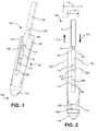
- FIGS. 1 and 2illustrate a suture anchor 100 and inserter attachment 102 attached to the suture anchor 100, according to embodiments of the present invention.
- the suture anchor 100includes an expandable collar 107 which is connected to and slides with respect to an implant body 210.
- the implant body 210terminates at its distal end with a conical nose member 116 for insertion into a bone or a bone hole, according to embodiments of the present invention.
- the proximal end of the implant body 210includes a spreader 106, which is operatively attached to the inserter attachment 102 by a detachment or breakaway feature 104, according to embodiments of the present invention.
- a slider 110slides proximally and distally within, along, or across a notch 150 formed in the implant body 210, between a distal edge 112 and a proximal edge 114 of the notch 150, according to embodiments of the present invention.
- Notch 150may also be referred to as slot 150.
- Slot 150is formed in the implant body 210 at least partially longitudinally; in other words, at least one component of the slot is in a longitudinal direction, wherein the longitudinal direction is the direction along the length of the implant between the proximal end 152 and distal end 152 of the implant body 210.
- the implant body 210includes the nose member 116, the slot 150, and the spreader 106 which are formed as a unitary assembly.
- the implant bodyis constructed (e.g. molded) of a single continuous piece of material.
- the spreader 106is wider at its distal end near edge 114, and narrower at its proximal end near detachment feature 104; this causes the collar 107 to spread or expand when the implant body 210 is moved in the direction indicated by arrow 212 with respect to the collar 107, or when the collar 107 is moved in the direction indicated by arrow 214 with respect to the implant body 210, according to embodiments of the present invention.
- the collar 107includes a slot 119 which divides the collar 107 into halves and facilitates the expansion of the collar 107. Each such half may be referred to as an anchor fin 108. In FIG.
- the fins 108are depicted in the non-deployed state, while the deployed state of fins is illustrated in dashed lines at reference number 108'.
- the rest of the implant body 210also slides proximally with respect to the collar 107 until the bottom 202 of the collar 107 contacts or nears the top of the nose member 116, according to embodiments of the present invention.
- the furthest proximal extent of the implant body 210 and spreader 106is limited by the abutment of the bottom edge 202 of collar 107 with the top edge 204 of the nose member 116.
- the slider 110is configured to slide along the slot 150 both before and after implantation of the suture anchoring system 100.
- Collar 107is slidably coupled with the implant body 210, the collar 107 includes one or more anchor fins 108, the collar 107 is slideable with respect to the implant body 210 between at least an implant position (as illustrated in solid lines in FIG. 2 ) in which the one or more anchor fins have a maximum lateral dimension D1 smaller than or the same as that of the insertion nose 116, and deployed position (illustrated partially in phantom lines in FIG. 2 ) in which the maximum lateral dimension D2 is larger than that of the insertion nose 116, according to embodiments of the present invention.
- FIGS. 3 through 5illustrate a method for installing or implanting the anchor 100, according to embodiments of the present invention.
- the inserter attachment 102attaches the implant body 210 with the inserter 101.
- the inserter 101has an outer lateral dimension at its distal end 103 that is smaller than or the same as that of the insertion nose, the inserter 101 coupled to the inserter attachment 102 in a manner which permits actuation of the inserter 101 to slide the collar 107 with respect to the implant body 210.
- the suture anchor 100which is attached to the inserter 101 via the inserter attachment 102, is placed within a hole 304 in the bone 302.
- the anchor 100 and inserter 101 and fins 108may be of a substantially uniform diameter and/or cylindrical shape to easily fit within the hole 304, as illustrated in FIG. 3 , according to embodiments of the present invention.
- the hole 304is pre-drilled.
- the inserter 101may include a substantially hollow tube 132 at its distal end which contains and/or holds within it the inserter attachment 102, according to embodiments of the present invention.
- the inserter 101comprises an outer shaft 132 and an inner shaft 134, wherein the outer shaft 132 slides with respect to the inner shaft 134, wherein the inner shaft 134 is rigidly coupled to the inserter attachment 102, and wherein the outer shaft 132 is configured to abut a proximal end 111 of the collar 107.
- the inserter 101comprises an outer shaft 132 only, which is configured to receive the inserter attachment 102, wherein the outer shaft 132 slides with respect to inserter attachment 102.
- the inserter 101is pushed in a distal direction, thereby permitting the distal end of the inserter 101 to contact the top of the collar 107.
- the collar 107moves in a distal direction with respect to the implant body 210, which causes the spreader 106 to expand or spread the fins 108 outwardly to engage the surrounding bone 302, according to embodiments of the present invention.
- the inserter 101may be pulled in a proximal direction to break the connection between the inserter 101 and inserter attachment 102 at detachment feature 104, as illustrated in FIG. 5 , thus leaving the spreader 106 implanted in the bone 302.
- the inserter 101 and inserter attachment 102may be connected in a way that permits the inserter 101 to slide distally over the inserter attachment 102, but which does not permit the inserter attachment 102 to fall out or off of the inserter 101 after the inserter attachment is broken from the spreader 106 at detachment feature 104, according to embodiments of the present invention.
- the inserter attachment 102is detached at the detachment feature 104 while the inserter 101 is being pushed against the collar 107, rather than afterward.
- the outer tube of the inserter 101includes inwardly projecting teeth which slide easily over the detachment feature 104 in the distal direction, but which securely grasp the inserter attachment 102 at the detachment feature 104 when slid back in the proximal direction, thereby also retaining the inserter attachment 102 within the inserter 101 after the inserter attachment 102 has broken off at breakaway feature 104.
- the detachment feature 104is depicted as a set of notches on both sides of the inserter attachment 102, one of ordinary skill in the art will appreciate, based on the present disclosure, the structural weaknesses and/or various mechanisms that may be used to impart a breakaway or detachment performance at detachment feature 104 location.
- the inserter attachment 102may be connected to the spreader 106 at detachment feature 104 by a weak adhesive connection, a twisted connection, a twist-off connection, a precut connection, a perforated connection, a string connection, and/or the like, such that a force or action required to detach the inserter attachment 102 from the spreader 106 does not disturb or disengage the suture anchor 100.
- the inserter 101 and/or insertion attachment 102may also include graduations or other markings or registrations to assist the surgeon in achieving or evaluating the position and/or depth of the suture anchor 100, according to embodiments of the present invention.
- the suture anchor 100Prior to anchoring within bone 302, the suture anchor 100 may be loaded with suture in either a knotless fashion or a knotted fashion, according to embodiments of the present invention.
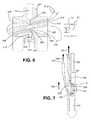
- FIGS. 6 and 7illustrate loading of the suture anchor 100 in a knotless fashion.
- the suture illustrated in FIG. 6is a double suture, or loop, having a looped end 614 and a pair of suture tails 612 at the other end, according to embodiments of the present invention.
- the looped end 614may be looped through and/or attached to tissue or some other material that the surgeon will secure and/or place in tension with the suture, according to embodiments of the present invention.
- the suture anchor 100includes two apertures at least partially formed by the slider 110. As shown in FIG. 2 , a first aperture 230 is formed at least partially by the distal end 112 of the notch in the implant body 210 and the distal (or bottom) end 208 of the slider 110. A second aperture 232 is formed at least partially by the proximal (or top) end 206 of the slider 110 and the proximal (or top) end 114 of the notch in the implant body 210, which is also the distal (or bottom) end 114 of the spreader 106, according to embodiments of the present invention.
- FIG. 6illustrates the suture anchor 100 within a loader device 602 which facilitates loading the suture through apertures 230, 232 in the suture anchor 100.
- FIG. 17also illustrates an inserter 101 with a loader 602 and implant 100 therein.
- a device like loader 602reduces the time necessary to perform a given operation.
- the device 602includes openings 604, 608 larger than the apertures 230, 232 in the suture anchor 100, to facilitate threading or loading of the suture through the suture anchor 100.
- the suture tails 612are first placed through opening 604 in the loader 602, which narrows in size similar to a funnel and aligns with aperture 230 to pass the suture through the aperture 230 and out of the opening 606 on the other side of loader 602.
- the suture tails 612are then placed through opening 608, which narrows in size and aligns with aperture 232 to pass the suture through the aperture 232 and out of opening 610 on the other side of loader 602.
- the loader 602may then be removed from the suture anchor 100 and inserter 101, while leaving the suture threaded through apertures 230, 232.
- the loader 602has two corresponding halves that open at a hinge, or that removably snap-fit together.
- the loader 602includes an inner cavity 616 configured to receive the distal end of the inserter 101 and the implant body 210, an outer surface 618, an opening 604 formed in the loader 602, the opening 604 extending from the outer surface 618 to the inner cavity 616, wherein the opening 604 has a first opening area 620 at the outer surface 618 and a second opening area 622 at the inner cavity 616, the first opening area 620 being larger than the second opening area 622, according to embodiments of the present invention.
- the area A1 of the first opening area 620is at least twice as large as the area A2 of the second opening area 622.
- the loader 602may also include an alignment feature configured to align one of the first and second apertures 230, 232 with the second opening area 622 when the distal end of the inserter 101 and the implant body 210 are received by the inner cavity 616.
- one or more pin or ball members 624may serve as alignment features, by interfacing with a slot on the implant body 210 or between implant body 210 and collar 107, to ensure that the position and orientation of the distal end of the inserter 101 and implant body 210 are known when received by the loader 602.
- the alignment featureis a feature which aligns the first aperture 230 with the second opening area 622 when the anchor 100 is received by the loader 602, to permit easy threading of suture therethrough.
- Opening 608may have characteristics similar to those of opening 604, according to embodiments of the present invention, but may be formed from an opposite side of the outer surface 618 as illustrated in FIG. 6 .
- FIG. 7illustrates the suture anchor 100 after the suture has been loaded in a knotless configuration.
- the ends 612may be pulled by the surgeon to tighten the tension on end 614.
- the tension on end 614pushes the slider 110 in the direction indicated by arrow 702, which pinches or "cinches” or otherwise holds the suture between edge 114 of the implant body 210 and edge 206 of the slider 110, according to embodiments of the present invention.
- the harder the surgeon pulls ends 612the tighter the suture is held between the slider 110 and the spreader 106.
- the slider 110thus operates to permit the suture to slide through the suture anchor 100 when ends 612 are pulled in direction 704, while also prohibiting movement of the suture toward end 614 in direction 706, thereby inhibiting an unintended loosening of the tension on the tissue side 614 of the suture.
- FIGS. 6 and 7illustrate a suture loop
- a suture loopmay be loaded through the anchor 100 in the knotless configuration either before or after the suture has been passed through tissue, according to embodiments of the present invention.
- This knotless suture pathalso permits the surgeon to successively and selectively tighten the tension on end 614; for example, the surgeon may place a smaller amount of tension on end 614 by pulling suture tails 612 of the suture loop in direction 704, this smaller amount of tension being maintained by the locking mechanism of pinching between the slider 110 and the slot 150, and the surgeon may return later in the operation to add further tension to the end 614 by further pulling suture tails 612 in direction 704, and this may all be accomplished after implantation of the anchor 100.
- FIGS. 8 and 9illustrate a loading of the suture anchor 100 for a knotted deployment.
- One end of the suture 802may be attached to tissue or other material, and the other end 804 of the suture may be placed through opening 604, through aperture 230, and out of opening 606.
- the suture anchor 100 with the suture in a knotted configurationis illustrated in FIG. 9 .
- the sutureis able to slide freely back and forth through aperture 230, and may be placed through tissue or other material and knotted; for example, the two ends 802, 804 may be knotted together, according to embodiments of the present invention.
- loading the suture through the suture anchor 100 in a knotted configurationincludes threading the suture through aperture 232 instead of aperture 230.
- the tension forces on the suturein either the knotted or the knotless configurations, pull the implant body 210 proximally with respect to the collar 107, which serves to enhance and maintain the expansion of the collar 107 within the bone hole 304, promoting the continued secure anchoring of suture anchor 100 within bone hole 304.
- loader 602is illustrated as being usable to load suture into the anchor 100 of FIGS. 1 and 2
- different loaders 602may have different dimensions in order to accommodate various different kinds of suture anchors having apertures formed by a slot and a slider.
- a similar loader 602may be used to facilitate loading of suture through the apertures of the anchors or locking mechanisms of FIGS. 12-18 , with each loader having an inner cavity 614 sized to accept a particular anchor.
- Openings 604, 608 of the loader 602may be substantially parallel to each other, may be separated by walls within the loader 602, and may have a circular, oval, rectangular, or other cross sectional shape, according to embodiments of the present invention.
- Openings 604, 608facilitate suture passage, with or without a needle, according to embodiments of the present invention.
- the inner cavity 614has variable dimensions adapted to different implant models, which present varying dimensions.
- the loader 602may have deformable and/or elastomeric walls which adapt to implants having different diameters, according to embodiments of the present invention.
- a suture passed through only one of the first and second apertures 230, 232 before implantationis moveable freely in both directions 808, 810 (e.g. the suture travel directions achieved by pulling on either end of the suture) after implantation; while a suture threaded, before implantation, through one of the first and second apertures 230, around the slider 110, and back through the other of the first and second apertures 232 (see FIG. 7 ) is, after implantation, moveable freely in a first direction 704 but substantially inhibited from moving in a second direction 706 opposite the first direction.
- loader device 602is illustrated for facilitating the loading or threading of the suture through one or more apertures 230, 232, one of ordinary skill in the art, based on the present disclosure, will appreciate that such loading may be accomplished by hand, without the assistance of a loader device, as illustrated in FIGS. 10 and 11 .
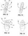
- FIGS. 12 and 13the longitudinal slot is formed by one ring 1202, and the other ring 1204 operates as a slider.
- One of the rings, 1202 in the present caseis rigidly coupled with the implant body, such as implant body 210.
- Suturesmay be selectively threaded through apertures 1206, 1208 in a knotless configuration (as illustrated in FIG. 12 ), or in a knotted configuration (as illustrated in FIGS. 13 ).
- the longitudinal element 1302has a longitudinal slot formed therein, and the slider ring 1304 slides along element 1302 to separate the longitudinal slot into a first aperture 1306 and a second aperture 1308, which may be threaded in the knotless configuration (as illustrated in FIG. 14 ) or in the knotted configuration (as illustrated in FIG. 15 ), according to embodiments of the present invention.
- the distal looppulls upwardly against one of the two interacting elements to pinch or squeeze the suture between such element and the other element.
- a similar slider mechanism 110may also be used with other implant bone fixation mechanisms; for example, a slider 1402 within a pressure fit fixation anchor body 1404 as illustrated in FIG. 16 , or a slider 1502 within a fixture 1504 mounted within an outer anchor body 1506 with one or more threads 1508 which turns independently of the fixture 1504 and/or slider 1502 as illustrated in FIG. 17 , or a slider 1602 within an expanding collar assembly as illustrated in FIG. 18 , according to embodiments of the present invention.
- a slider 1402 within a pressure fit fixation anchor body 1404 as illustrated in FIG. 16or a slider 1502 within a fixture 1504 mounted within an outer anchor body 1506 with one or more threads 1508 which turns independently of the fixture 1504 and/or slider 1502 as illustrated in FIG. 17 , or a slider 1602 within an expanding collar assembly as illustrated in FIG. 18 , according to embodiments of the present invention.
- the slider 1402, 1502, 1602creates a proximal aperture and a distal aperture, and the free end of the suture may be loaded through the distal aperture and then through the proximal aperture to impart knotless performance, and can be loaded through the distal aperture only (or, alternatively, through the proximal aperture only) to impart knotted capability, according to embodiments of the present invention.
- FIG. 19illustrates an inserter 101, according to embodiments of the present invention.
- a loader 602is mounted on a distal end of the inserter 101, and the proximal end of the inserter 101 comprises a knob or handle 1901 which, along with the inserter shaft 1902, may be used by the surgeon to position, insert, and/or manipulate the implant 100 into the bone 320.
- the knob 1901is adapted to include a grip that is practical and comfortable for the surgeon.
Landscapes
- Health & Medical Sciences (AREA)
- Surgery (AREA)
- Life Sciences & Earth Sciences (AREA)
- Biomedical Technology (AREA)
- Nuclear Medicine, Radiotherapy & Molecular Imaging (AREA)
- Engineering & Computer Science (AREA)
- Rheumatology (AREA)
- Heart & Thoracic Surgery (AREA)
- Medical Informatics (AREA)
- Molecular Biology (AREA)
- Animal Behavior & Ethology (AREA)
- General Health & Medical Sciences (AREA)
- Public Health (AREA)
- Veterinary Medicine (AREA)
- Surgical Instruments (AREA)
Description
- The present invention relates generally to suture anchors for bone implantation, and more specifically to suture anchors with multiple kinds of anchoring capabilities.
- An orthopedic surgery may involve different kinds of repairs within the same procedure. For example, an operation to repair shoulder instability may include capsular shifts, labral reattachments, or some combination of the two activities. In some cases, a simple knotted suture anchor may provide a desired solution, while in other cases, a more elegant, knotless suture anchor may better accomplish the surgeon's purposes. Existing suture anchors for implantation into bone are typically either for use with knotted sutures or for use with a knotless suture anchoring technique, but not both. However, the particular suture anchoring requirements may not become apparent until after a surgical procedure has begun.
WO-A-2008 109 087 , on which is based the preamble of appended claim 1, discloses, in Figures 31A-31C, a suture anchoring system comprises two side-by-side rings, namely a fixed ring and a slidable ring: in order to inhibit a suture from moving, the two rings slide past each other and can therefore generate a shear force and apply a torque to the suture. - The present invention concerns a suture anchoring system as defined by claim 1. Embodiments of this suture anchoring system are defined by claims 2 to 13.
- Some embodiments of the present invention include a suture anchor with both knotless and knotted suture attachment capabilities, as well as methods for loading the suture in knotless and knotted configurations. Some embodiments of the present invention include a suture anchor with an inner implant body with an inverted wedge or spreader that slides in relation to an outer expandable collar, such that pushing the expandable collar distally with an inserter causes the spreader to expand the collar against the surrounding bone to secure the suture anchor in place. Such embodiments may also include a detachment or breakaway feature between the inserter and the suture anchor to permit separation after anchor deployment. The present application also describes methods for deploying such suture anchors and expanding the expandable collars and/or detaching the inserter tools. These methods may be used in various orthopedic applications such as, for example, shoulder repair.
- A suture anchoring system according to embodiments of the present invention includes an implant body extending substantially longitudinally from a proximal end to a distal end, the implant body including an insertion nose at the distal end, the insertion nose configured for insertion into bone, a slot formed in the implant body, the slot extending at least partially longitudinally, the slot having a slot proximal edge and a slot distal edge, and a slider that slides along the slot, the slider comprising a slider proximal edge and a slider distal edge, a first aperture at least partially formed by the slot distal edge and the slider distal edge, and a second aperture at least partially formed by the slot proximal edge and the slider proximal edge, the second aperture located proximally with respect to the first aperture, wherein the slider is configured to slide along the slot both before and after implantation of the implant body, such that a suture passed through only one of the first and second apertures before implantation is moveable freely in both directions after implantation, and such that a suture threaded, before implantation, through one of the first and second apertures, around the slider, and back through the other of the first and second apertures is, after implantation, moveable freely in a first direction but substantially inhibited from moving in a second direction opposite the first direction.
- The suture anchoring system of paragraph [0005], wherein when a suture is threaded through one of the first and second apertures, around the slider, and back through the other of the first and second apertures, the suture moves freely in the first direction, but is pinched between the slider and the slot when moved in the second direction.
- The suture anchoring system of any of paragraphs [0005] or [0006], further including a collar slidably coupled with the implant body, the collar including one or more anchor fins, the collar slideable with respect to the implant body between at least an implant position in which the one or more anchor fins have a maximum lateral dimension smaller than or the same as that of the insertion nose, and a deployed position in which the maximum lateral dimension is larger than that of the insertion nose.
- The suture anchoring system of any of paragraphs [0005] to [0007], wherein the implant body includes a spreader configured to move the one or more least an implant position in which the one or more anchor fins have a maximum lateral dimension smaller than or the same as that of the insertion nose, and a deployed position in which the maximum lateral dimension is larger than that of the insertion nose.
- The suture anchoring system of any of paragraphs [0005] to [0007], wherein the implant body includes a spreader configured to move the one or more anchor fins between the implant position and the deployed position as the collar is slid with respect to the implant body.
- The suture anchoring system of any of paragraphs [0005] to [0008], wherein a proximal end of the spreader is narrower than a distal end of the spreader, anchor fins between the implant position and the deployed position as the collar is slid with respect to the implant body.
- The suture anchoring system of any of paragraphs [0005] to [0008], wherein a proximal end of the spreader is narrower than a distal end of the spreader, such that sliding the collar distally with respect to the implant body moves the collar from the implant position to the deployed position.
- The suture anchoring system of any of paragraphs [0005] to [0009], further including an inserter attachment coupled to the proximal end of the implant body with a break-away coupling.
- The suture anchoring system of any of paragraphs [0005] to [0010], further including an inserter having an outer lateral dimension at its distal end that is smaller than or the same as that of the insertion nose, the inserter coupled to the inserter attachment in a manner which permits actuation of the inserter to slide the collar with respect to the implant body.
- The suture anchoring system of any of paragraphs [0005] to [0011], wherein the inserter includes an outer shaft and an inner shaft, wherein the outer shaft slides with respect to the inner shaft, wherein the inner shaft is rigidly coupled to the inserter attachment, and wherein the outer shaft is configured to abut a proximal end of the collar.
- The suture anchoring system of any of paragraphs [0005] to [0011], wherein the inserter includes an outer shaft configured to receive the inserter attachment, wherein the outer shaft slides with respect to inserter attachment.
- The suture anchoring system of any of paragraphs [0005] to [0013], wherein the inserter is configured to decouple the inserter attachment from the proximal end of the implant body at the break-away coupling by moving the collar from the implant position to the deployed position.
- The suture anchoring system of any of paragraphs [0005] to [0014], further including a loader which includes an inner cavity configured to receive the implant body (or alternatively, both the distal end of the inserter and the implant body), an outer surface, an opening formed in the loader, the opening extending from the outer surface to the inner cavity, wherein the opening has a first opening area at the outer surface and a second opening area at the inner cavity, the first opening area being larger than the second opening area, and an alignment feature, wherein the alignment feature is configured to align one of the first and second apertures with the second opening area when the distal end of the inserter and the implant body are received by the inner cavity.
- The suture anchoring system of any of paragraphs [0005] to [0015], wherein the opening is a first opening, the loader further including a second opening formed in the loader, the second opening extending from the outer surface to the inner cavity, wherein the second opening has a third opening area at the outer surface and a fourth opening area at the inner cavity, the third opening area being larger than the fourth opening area, wherein the alignment feature is further configured to align the second opening area with the first aperture and the fourth opening area with the second aperture when the distal end of the inserter and the implant body are received by the inner cavity.
- The suture anchoring system of any of paragraphs [0005] to [0016], wherein the first opening area is at least twice as large as the second opening area.
- The present application also describes a method for suture anchoring.This method includes determining, before implanting a suture anchor, whether to employ knotless or knotted suture attachment using the suture anchor, and threading suture through the suture anchor of paragraph [0005] based on the determination, and sliding the suture in at least one direction with respect to the suture anchor after implantation of the suture anchor.
- The method of paragraph [0018], wherein the determination is a determination to use knotless suture attachment, wherein threading the suture through the suture anchor further includes threading the suture through one of the first and second apertures, around the slider, and back through the other of the first and second apertures.
- The method of any of paragraphs [0018] and [0019], further including passing the suture through a tissue to form a suture loop having two free ends, wherein threading the suture through the suture anchor further includes threading the two free ends through the one of the first and second apertures, around the slider, and back through the other of the first and second apertures.
- The method of paragraph [0018], wherein the determination is a determination to use knotted suture attachment, wherein threading the suture through the suture anchor further includes threading the suture through only one of the first and second apertures.
- The method of any of paragraphs [0018] and [0021], further including passing the suture through a tissue to form a suture loop having two free ends, wherein threading the suture through the suture anchor further includes threading the two free ends through the only one of the first and second apertures.
- The method of any one of paragraphs [0018] to [0022], wherein the suture anchor further includes a collar slidably coupled with the implant body, the collar including one or more anchor fins, the method further including sliding the collar with respect to the implant body between at least an implant position in which the one or more anchor fins have a maximum lateral dimension smaller than or the same as that of the insertion nose, and a deployed position in which the maximum lateral dimension is larger than that of the insertion nose.
- The method of any one of paragraphs [0018] to [0023], wherein the suture anchor further includes an inserter attachment coupled to the proximal end of the implant body with a break-away coupling, the method further including decoupling the inserter attachment from the implant body at the break-away coupling.
- The method of any one of paragraphs [0018] to [0024], wherein the suture anchor further includes an inserter having an outer lateral dimension at its distal end that is smaller than or the same as that of the insertion nose, the method further including actuating the inserter to slide the collar with respect to the implant body.
- The method of any one of paragraphs [0018] to [0025], wherein the inserter includes an outer shaft and an inner shaft, wherein the inner shaft is rigidly coupled to the inserter attachment, wherein the outer shaft is configured to abut a proximal end of the collar, and wherein actuating the inserter includes pushing the collar distally relative to the implant body with the outer shaft while pulling the implant body proximally relative to the collar with the inner shaft.
- The method of any one of paragraphs [0018] to [0026], wherein the suture anchor further includes the loader of paragraph [0015], and wherein threading the suture through the at least one of the first and second apertures includes inserting the suture through the opening from the outer surface to the inner surface and then through the at least one of the first and second apertures.
- While multiple embodiments of a suture anchoring system according to the invention are disclosed, still other embodiments of the present invention will become apparent to those skilled in the art from the following detailed description, which shows and describes illustrative embodiments of the invention. Accordingly, the drawings and detailed description are to be regarded as illustrative in nature and not restrictive.
FIG. 1 illustrates a front perspective view of a suture anchor and inserter attachment, according to embodiments of the present invention.FIG. 2 illustrates a front elevation view of the suture anchor and inserter attachment ofFIG. 1 , according to embodiments of the present invention.FIG. 3 illustrates a front cross sectional view of a suture anchor and inserter during installation in a bone hole, according to embodiments of the present invention.FIG. 4 illustrates a front cross sectional view of the suture anchor and inserter ofFIG. 3 after activation of the spreader, according to embodiments of the present invention.FIG. 5 illustrates a front cross sectional view of the suture anchor ofFIGS. 3 and 4 after removal of the inserter, according to embodiments of the present invention.FIG. 6 illustrates a side cross sectional view of a suture anchor, inserter, and loader, with a knotless suture configuration, according to embodiments of the present invention.FIG. 7 illustrates a side cross sectional view of a suture anchor with a knotless suture configuration, according to embodiments of the present invention.FIG. 8 illustrates a side cross sectional view of a suture anchor, inserter, and loader, with a knotted suture configuration, according to embodiments of the present invention.FIG. 9 illustrates a side cross sectional view of a suture anchor with a knotted suture configuration, according to embodiments of the present invention.FIG. 10 illustrates a method for manually loading a suture into a suture anchor in a knotless configuration without a loader device, according to embodiments of the present invention.FIG. 11 illustrates a method for manually loading a suture into a suture anchor in a knotted configuration without a loader device, according to embodiments of the present invention.FIG. 12 illustrates a variation of a slider plate suture anchoring system illustrating a knotless suture loading configuration, not according to the present invention.FIG. 13 illustrates a variation of a slider plate suture anchoring system illustrating a knotted suture loading configuration, not according to the present invention.FIG. 14 illustrates a variation of a slider plate suture anchoring system illustrating a knotless suture loading configuration, not according to the present invention.FIG. 15 illustrates a variation of a slider plate suture anchoring system illustrating a knotted suture loading configuration, not according to the present invention.FIG. 16 illustrates a slider plate used with a pressure fit anchor body, according to embodiments of the present invention.FIG. 17 illustrates a threaded anchor body that turns independently of a slider mechanism, according to embodiments of the present invention.FIG. 18 illustrates a slider mechanism included in an expanding collar assembly, according to embodiments of the present invention.FIG. 19 illustrates an inserter coupled with a suture anchor implant and loader device, according to embodiments of the present invention.- While the invention is amenable to various modifications and alternative forms, specific embodiments have been shown by way of example in the drawings and are described in detail below. The intention, however, is not to limit the invention to the particular embodiments described. On the contrary, the invention is intended to cover all modifications, equivalents, and alternatives falling within the scope of the invention as defined by the appended claims.
FIGS. 1 and 2 illustrate asuture anchor 100 andinserter attachment 102 attached to thesuture anchor 100, according to embodiments of the present invention. Thesuture anchor 100 includes anexpandable collar 107 which is connected to and slides with respect to animplant body 210. Theimplant body 210 terminates at its distal end with aconical nose member 116 for insertion into a bone or a bone hole, according to embodiments of the present invention. The proximal end of theimplant body 210 includes aspreader 106, which is operatively attached to theinserter attachment 102 by a detachment orbreakaway feature 104, according to embodiments of the present invention. Aslider 110 slides proximally and distally within, along, or across anotch 150 formed in theimplant body 210, between adistal edge 112 and aproximal edge 114 of thenotch 150, according to embodiments of the present invention.Notch 150 may also be referred to asslot 150.Slot 150 is formed in theimplant body 210 at least partially longitudinally; in other words, at least one component of the slot is in a longitudinal direction, wherein the longitudinal direction is the direction along the length of the implant between theproximal end 152 anddistal end 152 of theimplant body 210. According to embodiments of the present invention, theimplant body 210 includes thenose member 116, theslot 150, and thespreader 106 which are formed as a unitary assembly. According to some embodiments of the present invention, the implant body is constructed (e.g. molded) of a single continuous piece of material.- The
spreader 106 is wider at its distal end nearedge 114, and narrower at its proximal end neardetachment feature 104; this causes thecollar 107 to spread or expand when theimplant body 210 is moved in the direction indicated byarrow 212 with respect to thecollar 107, or when thecollar 107 is moved in the direction indicated byarrow 214 with respect to theimplant body 210, according to embodiments of the present invention. Thecollar 107 includes a slot 119 which divides thecollar 107 into halves and facilitates the expansion of thecollar 107. Each such half may be referred to as ananchor fin 108. InFIG. 2 , thefins 108 are depicted in the non-deployed state, while the deployed state of fins is illustrated in dashed lines atreference number 108'. In addition to thespreader 106 sliding proximally with respect to thefins 108 to spread thefins 108, the rest of theimplant body 210 also slides proximally with respect to thecollar 107 until thebottom 202 of thecollar 107 contacts or nears the top of thenose member 116, according to embodiments of the present invention. According to embodiments of the present invention, the furthest proximal extent of theimplant body 210 andspreader 106 is limited by the abutment of thebottom edge 202 ofcollar 107 with thetop edge 204 of thenose member 116. According to embodiments of the present invention, theslider 110 is configured to slide along theslot 150 both before and after implantation of thesuture anchoring system 100. Collar 107 is slidably coupled with theimplant body 210, thecollar 107 includes one ormore anchor fins 108, thecollar 107 is slideable with respect to theimplant body 210 between at least an implant position (as illustrated in solid lines inFIG. 2 ) in which the one or more anchor fins have a maximum lateral dimension D1 smaller than or the same as that of theinsertion nose 116, and deployed position (illustrated partially in phantom lines inFIG. 2 ) in which the maximum lateral dimension D2 is larger than that of theinsertion nose 116, according to embodiments of the present invention.FIGS. 3 through 5 illustrate a method for installing or implanting theanchor 100, according to embodiments of the present invention. Theinserter attachment 102 attaches theimplant body 210 with theinserter 101. Theinserter 101 has an outer lateral dimension at itsdistal end 103 that is smaller than or the same as that of the insertion nose, theinserter 101 coupled to theinserter attachment 102 in a manner which permits actuation of theinserter 101 to slide thecollar 107 with respect to theimplant body 210. First, thesuture anchor 100, which is attached to theinserter 101 via theinserter attachment 102, is placed within ahole 304 in thebone 302. In the non-deployed state, theanchor 100 andinserter 101 andfins 108 may be of a substantially uniform diameter and/or cylindrical shape to easily fit within thehole 304, as illustrated inFIG. 3 , according to embodiments of the present invention. In some embodiments of the present invention, thehole 304 is pre-drilled. Theinserter 101 may include a substantiallyhollow tube 132 at its distal end which contains and/or holds within it theinserter attachment 102, according to embodiments of the present invention.- According to some embodiments of the present invention, the
inserter 101 comprises anouter shaft 132 and aninner shaft 134, wherein theouter shaft 132 slides with respect to theinner shaft 134, wherein theinner shaft 134 is rigidly coupled to theinserter attachment 102, and wherein theouter shaft 132 is configured to abut aproximal end 111 of thecollar 107. According to other embodiments of the present invention, theinserter 101 comprises anouter shaft 132 only, which is configured to receive theinserter attachment 102, wherein theouter shaft 132 slides with respect toinserter attachment 102. - Once the
anchor 100 andinserter 101 are placed within thebone hole 304, theinserter 101 is pushed in a distal direction, thereby permitting the distal end of theinserter 101 to contact the top of thecollar 107. As illustrated inFIG. 4 , continuing to push down on thecollar 107 withinserter 101 and/or impulsing theinserter 101 onto thecollar 107 causes thecollar 107 to move in a distal direction with respect to theimplant body 210, which causes thespreader 106 to expand or spread thefins 108 outwardly to engage the surroundingbone 302, according to embodiments of the present invention. Once thefins 108 of thecollar 107 have been expanded, firmly engaging thesuture anchor 100 with the surroundingbone 302, theinserter 101 may be pulled in a proximal direction to break the connection between theinserter 101 andinserter attachment 102 atdetachment feature 104, as illustrated inFIG. 5 , thus leaving thespreader 106 implanted in thebone 302. Theinserter 101 andinserter attachment 102 may be connected in a way that permits theinserter 101 to slide distally over theinserter attachment 102, but which does not permit theinserter attachment 102 to fall out or off of theinserter 101 after the inserter attachment is broken from thespreader 106 atdetachment feature 104, according to embodiments of the present invention. - According to some embodiments of the present invention, the
inserter attachment 102 is detached at thedetachment feature 104 while theinserter 101 is being pushed against thecollar 107, rather than afterward. According to other embodiments of the present invention, the outer tube of theinserter 101 includes inwardly projecting teeth which slide easily over thedetachment feature 104 in the distal direction, but which securely grasp theinserter attachment 102 at thedetachment feature 104 when slid back in the proximal direction, thereby also retaining theinserter attachment 102 within theinserter 101 after theinserter attachment 102 has broken off atbreakaway feature 104. - Although the
detachment feature 104 is depicted as a set of notches on both sides of theinserter attachment 102, one of ordinary skill in the art will appreciate, based on the present disclosure, the structural weaknesses and/or various mechanisms that may be used to impart a breakaway or detachment performance atdetachment feature 104 location. For example, theinserter attachment 102 may be connected to thespreader 106 atdetachment feature 104 by a weak adhesive connection, a twisted connection, a twist-off connection, a precut connection, a perforated connection, a string connection, and/or the like, such that a force or action required to detach theinserter attachment 102 from thespreader 106 does not disturb or disengage thesuture anchor 100. - The
inserter 101 and/orinsertion attachment 102 may also include graduations or other markings or registrations to assist the surgeon in achieving or evaluating the position and/or depth of thesuture anchor 100, according to embodiments of the present invention. - Prior to anchoring within
bone 302, thesuture anchor 100 may be loaded with suture in either a knotless fashion or a knotted fashion, according to embodiments of the present invention.FIGS. 6 and 7 illustrate loading of thesuture anchor 100 in a knotless fashion. The suture illustrated inFIG. 6 is a double suture, or loop, having a loopedend 614 and a pair ofsuture tails 612 at the other end, according to embodiments of the present invention. The loopedend 614 may be looped through and/or attached to tissue or some other material that the surgeon will secure and/or place in tension with the suture, according to embodiments of the present invention. - The
suture anchor 100 includes two apertures at least partially formed by theslider 110. As shown inFIG. 2 , afirst aperture 230 is formed at least partially by thedistal end 112 of the notch in theimplant body 210 and the distal (or bottom) end 208 of theslider 110. Asecond aperture 232 is formed at least partially by the proximal (or top) end 206 of theslider 110 and the proximal (or top) end 114 of the notch in theimplant body 210, which is also the distal (or bottom) end 114 of thespreader 106, according to embodiments of the present invention. FIG. 6 illustrates thesuture anchor 100 within aloader device 602 which facilitates loading the suture throughapertures suture anchor 100.FIG. 17 also illustrates aninserter 101 with aloader 602 andimplant 100 therein. A device likeloader 602 reduces the time necessary to perform a given operation. Thedevice 602 includesopenings apertures suture anchor 100, to facilitate threading or loading of the suture through thesuture anchor 100. Thesuture tails 612 are first placed throughopening 604 in theloader 602, which narrows in size similar to a funnel and aligns withaperture 230 to pass the suture through theaperture 230 and out of theopening 606 on the other side ofloader 602. Thesuture tails 612 are then placed throughopening 608, which narrows in size and aligns withaperture 232 to pass the suture through theaperture 232 and out of opening 610 on the other side ofloader 602. Theloader 602 may then be removed from thesuture anchor 100 andinserter 101, while leaving the suture threaded throughapertures loader 602 has two corresponding halves that open at a hinge, or that removably snap-fit together.- The
loader 602 includes aninner cavity 616 configured to receive the distal end of theinserter 101 and theimplant body 210, anouter surface 618, anopening 604 formed in theloader 602, theopening 604 extending from theouter surface 618 to theinner cavity 616, wherein theopening 604 has afirst opening area 620 at theouter surface 618 and asecond opening area 622 at theinner cavity 616, thefirst opening area 620 being larger than thesecond opening area 622, according to embodiments of the present invention. According to embodiments of the present invention, the area A1 of thefirst opening area 620 is at least twice as large as the area A2 of thesecond opening area 622. Theloader 602 may also include an alignment feature configured to align one of the first andsecond apertures second opening area 622 when the distal end of theinserter 101 and theimplant body 210 are received by theinner cavity 616. For example, one or more pin orball members 624 may serve as alignment features, by interfacing with a slot on theimplant body 210 or betweenimplant body 210 andcollar 107, to ensure that the position and orientation of the distal end of theinserter 101 andimplant body 210 are known when received by theloader 602. For example, the alignment feature is a feature which aligns thefirst aperture 230 with thesecond opening area 622 when theanchor 100 is received by theloader 602, to permit easy threading of suture therethrough. Opening 608 may have characteristics similar to those of opening 604, according to embodiments of the present invention, but may be formed from an opposite side of theouter surface 618 as illustrated inFIG. 6 . FIG. 7 illustrates thesuture anchor 100 after the suture has been loaded in a knotless configuration. If loopedend 614 is connected to tissue and thesuture anchor 100 is inserted within a bone hole and expanded as described with respect toFIGS. 3-5 , theends 612 may be pulled by the surgeon to tighten the tension onend 614. The tension onend 614 pushes theslider 110 in the direction indicated byarrow 702, which pinches or "cinches" or otherwise holds the suture betweenedge 114 of theimplant body 210 and edge 206 of theslider 110, according to embodiments of the present invention. According to embodiments of the present invention, the harder the surgeon pulls ends 612, the tighter the suture is held between theslider 110 and thespreader 106. Theslider 110 thus operates to permit the suture to slide through thesuture anchor 100 when ends 612 are pulled indirection 704, while also prohibiting movement of the suture towardend 614 indirection 706, thereby inhibiting an unintended loosening of the tension on thetissue side 614 of the suture.- Although
FIGS. 6 and 7 illustrate a suture loop, one of ordinary skill the art, based on the disclosure presented herein, will appreciate that the knotless configuration illustrated and described may similarly be achieved with multiple suture loops and/or a single non-looped suture strand, according to embodiments of the present invention. A suture loop may be loaded through theanchor 100 in the knotless configuration either before or after the suture has been passed through tissue, according to embodiments of the present invention. This knotless suture path also permits the surgeon to successively and selectively tighten the tension onend 614; for example, the surgeon may place a smaller amount of tension onend 614 by pullingsuture tails 612 of the suture loop indirection 704, this smaller amount of tension being maintained by the locking mechanism of pinching between theslider 110 and theslot 150, and the surgeon may return later in the operation to add further tension to theend 614 by further pullingsuture tails 612 indirection 704, and this may all be accomplished after implantation of theanchor 100. FIGS. 8 and 9 illustrate a loading of thesuture anchor 100 for a knotted deployment. One end of thesuture 802 may be attached to tissue or other material, and theother end 804 of the suture may be placed throughopening 604, throughaperture 230, and out ofopening 606. Thesuture anchor 100 with the suture in a knotted configuration is illustrated inFIG. 9 . The suture is able to slide freely back and forth throughaperture 230, and may be placed through tissue or other material and knotted; for example, the two ends 802, 804 may be knotted together, according to embodiments of the present invention.- Although a single suture strand is illustrated, one of ordinary skill in the art, based on the present disclosure, will appreciate that multiple suture strands and/or looped suture strands may be loaded into the
suture anchor 100 in a knotted configuration, according to embodiments of the present invention. According to an alternative embodiment of the present invention, loading the suture through thesuture anchor 100 in a knotted configuration includes threading the suture throughaperture 232 instead ofaperture 230. According to embodiments of the present invention, the tension forces on the suture, in either the knotted or the knotless configurations, pull theimplant body 210 proximally with respect to thecollar 107, which serves to enhance and maintain the expansion of thecollar 107 within thebone hole 304, promoting the continued secure anchoring ofsuture anchor 100 withinbone hole 304. - Although the
loader 602 is illustrated as being usable to load suture into theanchor 100 ofFIGS. 1 and 2 ,different loaders 602 may have different dimensions in order to accommodate various different kinds of suture anchors having apertures formed by a slot and a slider. For example, asimilar loader 602 may be used to facilitate loading of suture through the apertures of the anchors or locking mechanisms ofFIGS. 12-18 , with each loader having aninner cavity 614 sized to accept a particular anchor.Openings loader 602 may be substantially parallel to each other, may be separated by walls within theloader 602, and may have a circular, oval, rectangular, or other cross sectional shape, according to embodiments of the present invention.Openings inner cavity 614 has variable dimensions adapted to different implant models, which present varying dimensions. Theloader 602 may have deformable and/or elastomeric walls which adapt to implants having different diameters, according to embodiments of the present invention. - In comparing
FIGS. 7 and9 , because theslider 110 is configured to slide along theslot 150 both before and after implantation of theimplant body 210, a suture passed through only one of the first andsecond apertures FIG. 9 ) is moveable freely in bothdirections 808, 810 (e.g. the suture travel directions achieved by pulling on either end of the suture) after implantation; while a suture threaded, before implantation, through one of the first andsecond apertures 230, around theslider 110, and back through the other of the first and second apertures 232 (seeFIG. 7 ) is, after implantation, moveable freely in afirst direction 704 but substantially inhibited from moving in asecond direction 706 opposite the first direction. This inhibition of suture movement is caused in the knotless configuration because asend 614 is tensioned, the tension essentially applies an upward force toslider 110, which, in turn, pinches the suture betweenslider 110 and the upper edge ofslot 150, according to embodiments of the present invention. - Although a
loader device 602 is illustrated for facilitating the loading or threading of the suture through one ormore apertures FIGS. 10 and 11 . - And although a
slider 110 mechanism is illustrated, one of ordinary skill in the art, based on the present disclosure, will appreciate that other pinching or cinching mechanisms may be employed to secure the suture in the knotless configuration while also permitting threading of the suture in the knotted configuration, for example the cinch ring configuration illustrated inFIGS. 12 and 13 or the fixed eyelet and crosspiece configuration illustrated inFIGS. 14 and 15 . In the ring cinch configuration ofFIGS. 12 and 13 , the longitudinal slot is formed by onering 1202, and theother ring 1204 operates as a slider. One of the rings, 1202 in the present case, is rigidly coupled with the implant body, such asimplant body 210. Sutures may be selectively threaded throughapertures FIG. 12 ), or in a knotted configuration (as illustrated inFIGS. 13 ). In the configuration ofFIGS 14 and 15 , thelongitudinal element 1302 has a longitudinal slot formed therein, and theslider ring 1304 slides alongelement 1302 to separate the longitudinal slot into afirst aperture 1306 and asecond aperture 1308, which may be threaded in the knotless configuration (as illustrated inFIG. 14 ) or in the knotted configuration (as illustrated inFIG. 15 ), according to embodiments of the present invention. In either of the embodiments ofFIGS. 12-15 , the distal loop pulls upwardly against one of the two interacting elements to pinch or squeeze the suture between such element and the other element. - A
similar slider mechanism 110 may also be used with other implant bone fixation mechanisms; for example, aslider 1402 within a pressure fitfixation anchor body 1404 as illustrated inFIG. 16 , or aslider 1502 within afixture 1504 mounted within anouter anchor body 1506 with one ormore threads 1508 which turns independently of thefixture 1504 and/orslider 1502 as illustrated inFIG. 17 , or aslider 1602 within an expanding collar assembly as illustrated inFIG. 18 , according to embodiments of the present invention. In each of these embodiments, theslider FIG. 19 illustrates aninserter 101, according to embodiments of the present invention. Aloader 602 is mounted on a distal end of theinserter 101, and the proximal end of theinserter 101 comprises a knob or handle 1901 which, along with theinserter shaft 1902, may be used by the surgeon to position, insert, and/or manipulate theimplant 100 into the bone 320. Theknob 1901 is adapted to include a grip that is practical and comfortable for the surgeon.- Various modifications and additions can be made to the exemplary embodiments discussed without departing from the scope of the present invention defined by claims. For example, while the embodiments described above refer to particular features, the scope of this invention defined by claims also includes embodiments having different combinations of features and embodiments that do not include all of the described features. Accordingly, the scope of the present invention is intended to embrace all such alternatives, modifications, and variations as fall within the scope of the claims, together with all equivalents thereof.
Claims (13)
- A suture anchoring system (100) comprising:an implant body (210; 1404; 1504) extending substantially longitudinally from a proximal end to a distal end, the implant body comprising:an insertion nose (116) at the distal end, the insertion nose being configured for insertion into bone;a slot (150) formed in the implant body (210), the slot extending at least partially longitudinally, the slot having a slot proximal edge and a slot distal edge; anda slider (110; 1402; 1502; 1602) comprising a slider proximal edge and a slider distal edge;characterized in that the slider (110; 1402; 1502; 1602) is configured to slide within the slot (150) both before and after implantation of the implant body (210; 1404; 1504),in that a first aperture (230) and a second aperture (232) for selectively receiving a suture (612, 614; 802, 804) in a knotless configuration or a knotted configuration of the suture anchoring system are at least partially formed in the suture anchoring system, respectively, by the slot distal edge and the slider distal edge for the first aperture (230) and by the slot proximal edge and the slider proximal edge for the second aperture (232), which is located proximally with respect to the first aperture,in that a suture passed through only one of the first and second apertures (230, 232) before implantation is moveable freely in both directions after implantation, andin that a suture threaded, before implantation, through one of the first and second apertures (230, 232), around the slider (110; 1402; 1502; 1602), and back through the other of the first and second apertures (230, 232) is, after implantation, moveable freely in a first direction but substantially inhibited from moving in a second direction opposite the first direction when, upon movement in the second direction, the suture disposed in the first aperture (230) pushes the slider (110; 1402; 1502; 1602) such that the suture disposed in the second aperture (232) is pinched between the slider proximal edge and the slot proximal edge.
- The suture anchoring system of claim 1, further comprising:a collar (107) slidably coupled with the implant body (210; 1404; 1504), the collar (107) comprising one or more anchor fins (108), the collar (107) being slideable with respect to the implant body (210; 1404; 1504) between at leastan implant position in which the one or more anchor fins (108) have a maximum lateral dimension smaller than or the same as that of the insertion nose (116), anda deployed position in which the maximum lateral dimension is larger than that of the insertion nose (116).
- The suture anchoring system of claim 2, wherein the implant body (210; 1302; 1404; 1504) comprises a spreader (106) configured to move the one or more anchor fins (108) between the implant position and the deployed position as the collar (107) is slid with respect to the implant body (210; 1404; 1504).
- The suture anchoring system of claim 3, wherein a proximal end of the spreader (106) is narrower than a distal end of the spreader (106), such that sliding the collar (107) distally with respect to the implant body (210; 1404; 1504) moves the collar (107) from the implant position to the deployed position.
- The suture anchoring system of claim 2, further comprising an inserter attachment (102) coupled to the proximal end of the implant body (210; 1404; 1504) with a break-away coupling (104).
- The suture anchoring system of claim 5, further comprising:an inserter (101) having an outer lateral dimension at its distal end that is smaller than or the same as that of the insertion nose (116), the inserter (101) being coupled to the inserter attachment (102) in a manner which permits actuation of the inserter (101) to slide the collar (107) with respect to the implant body (210; 1404; 1504).
- The suture anchoring system of claim 6, wherein the inserter (101) comprises an outer shaft (132) and an inner shaft (134), wherein the outer shaft (132) slides with respect to the inner shaft (134), wherein the inner shaft (134) is rigidly coupled to the inserter attachment (102), and wherein the outer shaft (132) is configured to abut a proximal end of the collar (107).
- The suture anchoring system of claim 6, wherein the inserter (101) comprises an outer shaft (132) configured to receive the inserter attachment (102), wherein the outer shaft (132) slides with respect to inserter attachment (102).
- The suture anchoring system of claim 7, wherein the inserter (101) is configured to decouple the inserter attachment (102) from the proximal end of the implant body (210; 1404; 1504) at the break-away coupling (104) by moving the collar (107) from the implant position to the deployed position.
- The suture anchoring system of claim 1, further comprising:a loader (602), the loader (602) comprising:an inner cavity (616) configured to receive the implant body (210; 1404; 1504);an outer surface (618);an opening (604) formed in the loader (602), the opening (604) extending from the outer surface (618) to the inner cavity (616), wherein the opening (604) has a first opening area (620) at the outer surface (618) and a second opening area (622) at the inner cavity (616), the first opening area (620) being larger than the second opening area (622); andan alignment feature, wherein the alignment feature is configured to align one of the first and second apertures (230, 232) with the second opening area (622) when the implant body (210; 1404; 1504) is received by the inner cavity (616).
- The suture anchoring system of claim 10, wherein the opening is a first opening, the loader (602) further comprising:a second opening (608) formed in the loader (602), the second opening (608) extending from the outer surface (618) to the inner cavity (616), wherein the second opening (608) has a third opening area at the outer surface (618) and a fourth opening area at the inner cavity (616), the third opening area being larger than the fourth opening area,wherein the alignment feature is further configured to align the second opening area (622) with the first aperture (230) and the fourth opening area with the second aperture (232) when the distal end of the implant body (210; 1404; 1504) is received by the inner cavity (616).
- The suture anchoring system of claim 10, wherein the first opening area (620) is at least twice as large as the second opening area (622).
- The suture anchoring system of claim 6, further comprising:a loader (602), the loader (602) comprising:an inner cavity (616) configured to receive the distal end of the inserter (101) and the implant body (210; 1404; 1504);an outer surface (618);an opening (604) formed in the loader (602), the opening (604) extending from the outer surface (618) to the inner cavity (616), wherein the opening (604) has a first opening area (620) at the outer surface (618) and a second opening area (622) at the inner cavity (616), the first opening area (620) being larger than the second opening area (622); andan alignment feature, wherein the alignment feature is configured to align one of the first and second apertures (230, 232) with the second opening area (622) when the distal end of the inserter (101) and the implant body (210; 1404; 1504) are received by the inner cavity (616).
Applications Claiming Priority (3)
| Application Number | Priority Date | Filing Date | Title |
|---|---|---|---|
| US26148009P | 2009-11-16 | 2009-11-16 | |
| FR1050965 | 2010-02-11 | ||
| PCT/US2010/056883WO2011060437A1 (en) | 2009-11-16 | 2010-11-16 | Bone implant with convertible suture attachment |
Publications (2)
| Publication Number | Publication Date |
|---|---|
| EP2501299A1 EP2501299A1 (en) | 2012-09-26 |
| EP2501299B1true EP2501299B1 (en) | 2016-03-23 |
Family
ID=42735791
Family Applications (1)
| Application Number | Title | Priority Date | Filing Date |
|---|---|---|---|
| EP10782499.7ANot-in-forceEP2501299B1 (en) | 2009-11-16 | 2010-11-16 | Bone implant with convertible suture attachment |
Country Status (3)
| Country | Link |
|---|---|
| US (2) | US9445805B2 (en) |
| EP (1) | EP2501299B1 (en) |
| WO (1) | WO2011060437A1 (en) |
Families Citing this family (31)
| Publication number | Priority date | Publication date | Assignee | Title |
|---|---|---|---|---|
| CA2702044C (en) | 2007-10-12 | 2013-09-10 | Edward Jordan Stoll, Jr. | Toggle bolt suture anchor kit |
| EP2501299B1 (en) | 2009-11-16 | 2016-03-23 | Tornier, Inc. | Bone implant with convertible suture attachment |
| US9713463B2 (en)* | 2011-01-13 | 2017-07-25 | Howmedica Osteonics Corp | Toggle bolt assembly and method of assembly |
| US8840644B2 (en) | 2011-03-24 | 2014-09-23 | Howmedica Osteonics Corp. | Toggle bolt suture anchor |
| US9636101B2 (en) | 2011-09-01 | 2017-05-02 | Arthrocare Corporation | Bone anchor having an integrated stress isolator |
| US9107653B2 (en)* | 2011-09-22 | 2015-08-18 | Arthrex, Inc. | Tensionable knotless anchors with splice and methods of tissue repair |
| US9023083B2 (en) | 2012-01-27 | 2015-05-05 | Arthrocare Corporation | Method for soft tissue repair with free floating suture locking member |
| US9364210B2 (en) | 2012-01-27 | 2016-06-14 | Arthrocare Corporation | Biased wedge suture anchor and method for soft tissue repair |
| US9226742B2 (en) | 2012-01-27 | 2016-01-05 | Arthrocare Corporation | Restricted wedge suture anchor and method for soft tissue repair |
| US9034014B2 (en) | 2012-01-27 | 2015-05-19 | Arthrocare Corporation | Free floating wedge suture anchor for soft tissue repair |
| US9855028B2 (en)* | 2012-04-06 | 2018-01-02 | Arthrocare Corporation | Multi-suture knotless anchor for attaching tissue to bone and related method |
| US10016192B2 (en) | 2013-06-14 | 2018-07-10 | Tornier, Inc. | Suture for connecting a human or animal tissue, soft anchor and method for attaching a tissue to a bone |
| US10575968B2 (en) | 2014-05-16 | 2020-03-03 | Howmedica Osteonics Corp. | Guides for fracture system |
| US9681960B2 (en) | 2014-05-16 | 2017-06-20 | Howmedica Osteonics Corp. | Guides for fracture system |
| CN104905859B (en)* | 2015-07-01 | 2017-11-24 | 上海凯利泰医疗科技股份有限公司 | For the fixing device of Cruciate ligament reconstruction, fixing means and application method |
| WO2017011185A1 (en)* | 2015-07-13 | 2017-01-19 | Smith & Nephew, Inc. | Knotless suture anchor with breakaway tip |
| US10258401B2 (en) | 2015-07-17 | 2019-04-16 | Kator, Llc | Transosseous guide |
| US9962174B2 (en) | 2015-07-17 | 2018-05-08 | Kator, Llc | Transosseous method |
| US10820918B2 (en) | 2015-07-17 | 2020-11-03 | Crossroads Extremity Systems, Llc | Transosseous guide and method |
| US10226243B2 (en) | 2015-08-04 | 2019-03-12 | Kator, Llc | Transosseous suture anchor |
| US12383253B2 (en) | 2015-08-04 | 2025-08-12 | Crossroads Extremity Systems, Llc | Suture anchor |
| US10335136B2 (en) | 2015-08-20 | 2019-07-02 | Arthrex, Inc. | Tensionable constructs with multi-limb locking mechanism through single splice and methods of tissue repair |
| US10265060B2 (en) | 2015-08-20 | 2019-04-23 | Arthrex, Inc. | Tensionable constructs with multi-limb locking mechanism through single splice and methods of tissue repair |
| JP6543765B2 (en) | 2015-10-06 | 2019-07-10 | カーディアック ペースメイカーズ, インコーポレイテッド | Welding device for subcutaneous electrode |
| FR3042965B1 (en)* | 2015-10-29 | 2020-11-20 | Transysteme Sn | ANCHOR FOR MEDICAL USE, INTENDED TO BE INSERTED INTO A BONE WALL |
| US9526494B1 (en) | 2015-12-18 | 2016-12-27 | Valeris Medical, Llc | Bone anchor delivery system device and method |
| US9517130B1 (en)* | 2016-05-24 | 2016-12-13 | Cardiac Implants Llc | Implanting a cinching cord into a cardiac valve annulus |
| WO2018118931A1 (en)* | 2016-12-21 | 2018-06-28 | Wright Medical Technology, Inc. | Syndesmosis construct |
| US10076322B1 (en) | 2018-01-11 | 2018-09-18 | Arthrex, Inc. | Tissue button |
| US11344290B1 (en) | 2021-12-16 | 2022-05-31 | Christopher Ninh | Knotless labral repair techniques and related devices |
| CN115778457A (en)* | 2022-11-10 | 2023-03-14 | 上海利格泰生物科技有限公司 | A bone implant, positioning sleeve, inserter and implantation system |
Family Cites Families (122)
| Publication number | Priority date | Publication date | Assignee | Title |
|---|---|---|---|---|
| US1562543A (en) | 1925-06-27 | 1925-11-24 | Seth J Cox | Screw driver |
| FR1050965A (en) | 1951-08-07 | 1954-01-12 | Zellwolle Lehrspinnerei Gmbh | two-strip stretching machine with upper rolls without lateral guide |
| US3527223A (en) | 1967-09-01 | 1970-09-08 | Melvin Shein | Ear stud and hollow piercer for insertion thereof |
| US3716058A (en) | 1970-07-17 | 1973-02-13 | Atlanta Res Inst | Barbed suture |
| US4170990A (en) | 1977-01-28 | 1979-10-16 | Fried. Krupp Gesellschaft Mit Beschrankter Haftung | Method for implanting and subsequently removing mechanical connecting elements from living tissue |
| US4485816A (en) | 1981-06-25 | 1984-12-04 | Alchemia | Shape-memory surgical staple apparatus and method for use in surgical suturing |
| US5601557A (en) | 1982-05-20 | 1997-02-11 | Hayhurst; John O. | Anchoring and manipulating tissue |
| US5190546A (en) | 1983-10-14 | 1993-03-02 | Raychem Corporation | Medical devices incorporating SIM alloy elements |
| US4665906A (en) | 1983-10-14 | 1987-05-19 | Raychem Corporation | Medical devices incorporating sim alloy elements |
| US4632100A (en) | 1985-08-29 | 1986-12-30 | Marlowe E. Goble | Suture anchor assembly |
| US4669473A (en) | 1985-09-06 | 1987-06-02 | Acufex Microsurgical, Inc. | Surgical fastener |
| US4898156A (en) | 1987-05-18 | 1990-02-06 | Mitek Surgical Products, Inc. | Suture anchor |
| US4870957A (en) | 1988-12-27 | 1989-10-03 | Marlowe Goble E | Ligament anchor system |
| US4946468A (en) | 1989-06-06 | 1990-08-07 | Mitek Surgical Products, Inc. | Suture anchor and suture anchor installation tool |
| US5002550A (en) | 1989-06-06 | 1991-03-26 | Mitek Surgical Products, Inc. | Suture anchor installation tool |
| NL8901526A (en) | 1989-06-16 | 1991-01-16 | Ordev Bv | SELF-ADJUSTING PROSTHESIS CONFIRMATION. |
| US5258016A (en) | 1990-07-13 | 1993-11-02 | American Cyanamid Company | Suture anchor and driver assembly |
| ATE174777T1 (en) | 1990-09-25 | 1999-01-15 | Innovasive Devices Inc | BONE FIXATION DEVICE |
| US5141520A (en) | 1991-10-29 | 1992-08-25 | Marlowe Goble E | Harpoon suture anchor |
| US5439467A (en) | 1991-12-03 | 1995-08-08 | Vesica Medical, Inc. | Suture passer |
| US5318579A (en) | 1992-09-21 | 1994-06-07 | Chow James C Y | Arthroscopic knot tying device |
| US5383905A (en) | 1992-10-09 | 1995-01-24 | United States Surgical Corporation | Suture loop locking device |
| US6406480B1 (en) | 1992-11-13 | 2002-06-18 | American Med Syst | Bone anchor inserter with retractable shield |
| US6635058B2 (en) | 1992-11-13 | 2003-10-21 | Ams Research Corporation | Bone anchor |
| US5972000A (en) | 1992-11-13 | 1999-10-26 | Influence Medical Technologies, Ltd. | Non-linear anchor inserter device and bone anchors |
| IL127978A0 (en) | 1999-01-08 | 1999-11-30 | Influence Med Tech Ltd | Incontinence device |
| US5522820A (en) | 1993-01-15 | 1996-06-04 | Arthrotech | Method and apparatus for suturing tissue |
| US5372599A (en) | 1993-03-12 | 1994-12-13 | Mitek Surgical Products, Inc. | Surgical anchor and method for deploying the same |
| US5356413A (en) | 1993-03-12 | 1994-10-18 | Mitek Surgical Products, Inc. | Surgical anchor and method for deploying the same |
| US5403348A (en) | 1993-05-14 | 1995-04-04 | Bonutti; Peter M. | Suture anchor |
| US5549630A (en) | 1993-05-14 | 1996-08-27 | Bonutti; Peter M. | Method and apparatus for anchoring a suture |
| US5505735A (en) | 1993-06-10 | 1996-04-09 | Mitek Surgical Products, Inc. | Surgical anchor and method for using the same |
| US5540718A (en) | 1993-09-20 | 1996-07-30 | Bartlett; Edwin C. | Apparatus and method for anchoring sutures |
| US5584835A (en) | 1993-10-18 | 1996-12-17 | Greenfield; Jon B. | Soft tissue to bone fixation device and method |
| US5391173A (en) | 1994-02-10 | 1995-02-21 | Wilk; Peter J. | Laparoscopic suturing technique and associated device |
| US5417712A (en) | 1994-02-17 | 1995-05-23 | Mitek Surgical Products, Inc. | Bone anchor |
| US5486197A (en) | 1994-03-24 | 1996-01-23 | Ethicon, Inc. | Two-piece suture anchor with barbs |
| US5843127A (en) | 1994-08-22 | 1998-12-01 | Le Medical Technologies, Inc. | Fixation device and method for installing same |
| US5462558A (en) | 1994-08-29 | 1995-10-31 | United States Surgical Corporation | Suture clip applier |
| US5522845A (en) | 1994-09-27 | 1996-06-04 | Mitek Surgical Products, Inc. | Bone anchor and bone anchor installation |
| US5649963A (en) | 1994-11-10 | 1997-07-22 | Innovasive Devices, Inc. | Suture anchor assembly and methods |
| FR2731610B1 (en) | 1995-03-16 | 1997-06-20 | Amp Dev | ANCHOR FOR INSERTION INTO A BONE CAVITY. |
| US5730747A (en) | 1995-06-07 | 1998-03-24 | Smith & Nephew, Inc. | Suture passing forceps |
| US6042583A (en) | 1995-06-14 | 2000-03-28 | Medworks Corporation | Bone anchor-insertion tool and surgical method employing same |
| US6451024B1 (en) | 1995-06-14 | 2002-09-17 | Dexterity Surgical, Inc. | Surgical method for treating urinary incontinence, and apparatus for use in same |
| US5662654A (en) | 1995-06-14 | 1997-09-02 | Incont, Inc. | Bone anchor, insertion tool and surgical kit employing same |
| FR2736254B1 (en) | 1995-07-07 | 1997-08-14 | Messaoudi Ali | DEVICE FOR PEELING CERTAIN FRUITS AND VEGETABLES |
| JPH11511357A (en) | 1995-08-25 | 1999-10-05 | グロッツ,アール・トーマス | Stabilizer for human joints |
| JP2897116B2 (en) | 1995-09-11 | 1999-05-31 | 株式会社ナカニシ | Screw tightening aid |
| US5662657A (en) | 1996-01-17 | 1997-09-02 | Sunmed, Inc. | Intramedullary bone plug |
| US5957953A (en) | 1996-02-16 | 1999-09-28 | Smith & Nephew, Inc. | Expandable suture anchor |
| US5702397A (en) | 1996-02-20 | 1997-12-30 | Medicinelodge, Inc. | Ligament bone anchor and method for its use |
| US5681352A (en) | 1996-03-06 | 1997-10-28 | Kinetikos Medical Incorporated | Method and apparatus for anchoring surgical ties to bone |
| US5961538A (en) | 1996-04-10 | 1999-10-05 | Mitek Surgical Products, Inc. | Wedge shaped suture anchor and method of implantation |
| US5893856A (en) | 1996-06-12 | 1999-04-13 | Mitek Surgical Products, Inc. | Apparatus and method for binding a first layer of material to a second layer of material |
| US5741300A (en) | 1996-09-10 | 1998-04-21 | Li Medical Technologies, Inc. | Surgical anchor and package and cartridge for surgical anchor |
| US5814054A (en) | 1996-09-23 | 1998-09-29 | Symbiosis Corporation | Automatic needle-passer suturing instrument |
| US5766218A (en) | 1996-10-01 | 1998-06-16 | Metamorphic Surgical Devices, Inc. | Surgical binding device and method of using same |
| US5948001A (en) | 1996-10-03 | 1999-09-07 | United States Surgical Corporation | System for suture anchor placement |
| CA2217406C (en) | 1996-10-04 | 2006-05-30 | United States Surgical Corporation | Suture anchor installation system with disposable loading unit |
| US5948002A (en) | 1996-11-15 | 1999-09-07 | Bonutti; Peter M. | Apparatus and method for use in positioning a suture anchor |
| IL121316A (en) | 1997-07-15 | 2001-07-24 | Litana Ltd | Implantable medical device of shape memory alloy |
| US5964770A (en) | 1997-09-30 | 1999-10-12 | Litana Ltd. | High strength medical devices of shape memory alloy |
| US5980558A (en) | 1997-09-30 | 1999-11-09 | Biomet Inc. | Suture anchor system |
| US6027523A (en) | 1997-10-06 | 2000-02-22 | Arthrex, Inc. | Suture anchor with attached disk |
| US5944724A (en) | 1997-10-30 | 1999-08-31 | Mitek Surgical Products, Inc. | Suture anchor insertion system |
| US6146406A (en) | 1998-02-12 | 2000-11-14 | Smith & Nephew, Inc. | Bone anchor |
| US5984927A (en) | 1998-03-03 | 1999-11-16 | Ethicon, Inc. | Device for sutureless attachment of soft tissue to bone |
| FR2777442B1 (en) | 1998-04-21 | 2000-07-28 | Tornier Sa | REVERSIBLE EXPANSION SUTURE ANCHOR |
| US6113611A (en) | 1998-05-28 | 2000-09-05 | Advanced Vascular Technologies, Llc | Surgical fastener and delivery system |
| US6997189B2 (en) | 1998-06-05 | 2006-02-14 | Broncus Technologies, Inc. | Method for lung volume reduction |
| US6200330B1 (en) | 1998-11-23 | 2001-03-13 | Theodore V. Benderev | Systems for securing sutures, grafts and soft tissue to bone and periosteum |
| US6066160A (en) | 1998-11-23 | 2000-05-23 | Quickie Llc | Passive knotless suture terminator for use in minimally invasive surgery and to facilitate standard tissue securing |
| GB9827415D0 (en) | 1998-12-11 | 1999-02-03 | Wild Andrew M | Surgical apparatus and method for occluding a body passageway |
| DE69931018T2 (en) | 1998-12-30 | 2006-11-23 | Ethicon, Inc. | Thread belay device |
| JP2002534149A (en) | 1999-01-08 | 2002-10-15 | インフルエンス・メディカル・テクノロジーズ・リミテッド | Tack device |
| US6299448B1 (en) | 1999-02-17 | 2001-10-09 | Ivanka J. Zdrahala | Surgical implant system for restoration and repair of body function |
| US6325805B1 (en) | 1999-04-23 | 2001-12-04 | Sdgi Holdings, Inc. | Shape memory alloy staple |
| US6210413B1 (en) | 1999-04-23 | 2001-04-03 | Sdgi Holdings, Inc. | Connecting apparatus using shape-memory technology |
| US7744613B2 (en) | 1999-06-25 | 2010-06-29 | Usgi Medical, Inc. | Apparatus and methods for forming and securing gastrointestinal tissue folds |
| US6287324B1 (en) | 2000-01-28 | 2001-09-11 | Shoulderon Ltd. | Self-drilling surgical suture anchor |
| US6585730B1 (en) | 2000-08-30 | 2003-07-01 | Opus Medical, Inc. | Method and apparatus for attaching connective tissues to bone using a knotless suture anchoring device |
| GB0025068D0 (en) | 2000-10-12 | 2000-11-29 | Browning Healthcare Ltd | Apparatus and method for treating female urinary incontinence |
| US6447524B1 (en) | 2000-10-19 | 2002-09-10 | Ethicon Endo-Surgery, Inc. | Fastener for hernia mesh fixation |
| US6527774B2 (en) | 2000-11-08 | 2003-03-04 | The Cleveland Clinic Foundation | Apparatus for attaching fractured sections of bone |
| US20040236170A1 (en) | 2000-11-15 | 2004-11-25 | Ducksoo Kim | Method for surgically joining a ventricular assist device to the cardiovascular system of a living subject using a piercing introducer assembly |
| WO2003049628A1 (en) | 2000-11-24 | 2003-06-19 | David Lee Kane | Collapsed deployable soft tissue anchor for repairing soft tissue to bone |
| US6692516B2 (en) | 2000-11-28 | 2004-02-17 | Linvatec Corporation | Knotless suture anchor and method for knotlessly securing tissue |
| US7083638B2 (en) | 2001-02-12 | 2006-08-01 | Arthrocare Corporation | Method and apparatus for attaching connective tissues to bone using a knotless suture anchoring device |
| US6770076B2 (en) | 2001-02-12 | 2004-08-03 | Opus Medical, Inc. | Method and apparatus for attaching connective tissues to bone using a knotless suture anchoring device |
| US7144363B2 (en) | 2001-10-16 | 2006-12-05 | Extensia Medical, Inc. | Systems for heart treatment |
| US7867251B2 (en) | 2001-11-08 | 2011-01-11 | Smith & Nephew, Inc. | Reattachment of tissue to base tissue |
| US6986781B2 (en) | 2001-11-08 | 2006-01-17 | Smith & Nephew, Inc. | Tissue repair system |
| US6855157B2 (en) | 2002-02-04 | 2005-02-15 | Arthrocare Corporation | Method and apparatus for attaching connective tissues to bone using a knotless suture anchoring device |
| US8100940B2 (en) | 2002-09-30 | 2012-01-24 | Quill Medical, Inc. | Barb configurations for barbed sutures |
| US7090690B2 (en) | 2002-11-19 | 2006-08-15 | Arthrocare Corporation | Devices and methods for repairing soft tissue |
| US7316706B2 (en) | 2003-06-20 | 2008-01-08 | Medtronic Vascular, Inc. | Tensioning device, system, and method for treating mitral valve regurgitation |
| US20040267275A1 (en) | 2003-06-26 | 2004-12-30 | Cournoyer John R. | Spinal implant holder and rod reduction systems and methods |
| US7556647B2 (en) | 2003-10-08 | 2009-07-07 | Arbor Surgical Technologies, Inc. | Attachment device and methods of using the same |
| US7588575B2 (en) | 2003-10-21 | 2009-09-15 | Innovative Spinal Technologies | Extension for use with stabilization systems for internal structures |
| US20080027440A1 (en) | 2004-01-30 | 2008-01-31 | Dsm Ip Assets B.V. | Fixing Device For Clamping The Ends Of A Surgical Cable Used For Fixing Bone Parts |
| DE102004009429A1 (en) | 2004-02-24 | 2005-09-22 | Biedermann Motech Gmbh | Bone anchoring element |
| US8162942B2 (en) | 2004-03-31 | 2012-04-24 | Orthofix S.R.L. | Intramedullary nail comprising elements of shape-memory material |
| US7938847B2 (en) | 2006-01-04 | 2011-05-10 | Tornier, Inc. | Ring cinch assembly to attach bone to tissue |
| US20050245932A1 (en) | 2004-04-16 | 2005-11-03 | Fanton Gary S | Apparatus and methods for securing tissue to bone |
| EP3087949B1 (en) | 2004-06-14 | 2018-07-25 | Boston Scientific Limited | System relating to implantable supportive slings |
| US8114127B2 (en) | 2004-06-22 | 2012-02-14 | Hs West Investments, Llc | Bone anchors for use in attaching soft tissue to bone |
| JP5393980B2 (en) | 2004-09-28 | 2014-01-22 | サージカル ソリューションズ リミテッド ライアビリティ カンパニー | Suture anchor |
| US7144415B2 (en)* | 2004-11-16 | 2006-12-05 | The Anspach Effort, Inc. | Anchor/suture used for medical procedures |
| US9089323B2 (en)* | 2005-02-22 | 2015-07-28 | P Tech, Llc | Device and method for securing body tissue |
| KR101145415B1 (en) | 2005-07-08 | 2012-05-15 | 비이더만 모테크 게엠베하 & 코. 카게 | Bone Anchoring Element |
| US8652172B2 (en) | 2006-02-03 | 2014-02-18 | Biomet Sports Medicine, Llc | Flexible anchors for tissue fixation |
| US20070255317A1 (en) | 2006-03-22 | 2007-11-01 | Fanton Gary S | Suture passer devices and uses thereof |
| EP2032044A2 (en)* | 2006-05-25 | 2009-03-11 | Mitralign, Inc. | Lockers for surgical tensioning members and methods of using the same to secure surgical tensioning members |
| US8758406B2 (en)* | 2007-03-05 | 2014-06-24 | Tomier, Inc. | Tack anchor systems, bone anchor systems, and methods of use |
| WO2009029468A2 (en) | 2007-08-24 | 2009-03-05 | C2M Medical, Inc. | Bone anchor comprising a shape memory element and uitilizing temperature transition to secure the bone anchor in bone |
| US20100292733A1 (en) | 2009-05-12 | 2010-11-18 | Foundry Newco Xi, Inc. | Knotless suture anchor and methods of use |
| EP2501299B1 (en) | 2009-11-16 | 2016-03-23 | Tornier, Inc. | Bone implant with convertible suture attachment |
| EP2704640B1 (en) | 2011-05-06 | 2021-07-07 | Linvatec Corporation | Soft anchor made from suture filament and suture tape |
| US20150182213A1 (en) | 2012-05-24 | 2015-07-02 | Suspension Orthopaedic Solutions, Llc | Collapsible Suture Anchor |
| EP2887885B1 (en) | 2012-08-22 | 2018-02-28 | Covidien LP | Tissue fixation device |
| US10016192B2 (en) | 2013-06-14 | 2018-07-10 | Tornier, Inc. | Suture for connecting a human or animal tissue, soft anchor and method for attaching a tissue to a bone |
- 2010
- 2010-11-16EPEP10782499.7Apatent/EP2501299B1/ennot_activeNot-in-force
- 2010-11-16WOPCT/US2010/056883patent/WO2011060437A1/enactiveApplication Filing
- 2010-11-16USUS13/510,240patent/US9445805B2/enactiveActive
- 2016
- 2016-06-21USUS15/188,234patent/US10736619B2/enactiveActive
Also Published As
| Publication number | Publication date |
|---|---|
| US9445805B2 (en) | 2016-09-20 |
| EP2501299A1 (en) | 2012-09-26 |
| WO2011060437A1 (en) | 2011-05-19 |
| US20130131723A1 (en) | 2013-05-23 |
| US10736619B2 (en) | 2020-08-11 |
| US20160296224A1 (en) | 2016-10-13 |
Similar Documents
| Publication | Publication Date | Title |
|---|---|---|
| EP2501299B1 (en) | Bone implant with convertible suture attachment | |
| US11534157B2 (en) | Method for coupling soft tissue to a bone | |
| US10842481B2 (en) | Method and apparatus for coupling soft tissue to bone | |
| US10368856B2 (en) | Apparatus for coupling soft tissue to a bone | |
| EP2189119B1 (en) | Suture anchor system with tension relief mechanism | |
| EP1884199B1 (en) | Suture anchor with lock and alignment mechanism | |
| US9370350B2 (en) | Apparatus for coupling soft tissue to a bone | |
| RU2416371C2 (en) | System and method of fastening soft tissue to bone | |
| US5690649A (en) | Anchor and anchor installation tool and method | |
| US9295460B2 (en) | Anchors and method for securing suture to bone | |
| EP2215972B1 (en) | Suture holding system | |
| US9414834B2 (en) | Knotless suture anchor and method of using same | |
| US20210219972A1 (en) | Syndesmosis construct | |
| WO1997020507A9 (en) | Anchor and anchor installation tool and method | |
| US20120143225A1 (en) | Endoscopic fascial closure devices and methods for using same | |
| EP3182902A1 (en) | Non-sliding soft anchor | |
| WO2008051481A2 (en) | Suture attachment device | |
| AU2013231063A1 (en) | System and method for attaching soft tissue to bone |
Legal Events
| Date | Code | Title | Description |
|---|---|---|---|
| PUAI | Public reference made under article 153(3) epc to a published international application that has entered the european phase | Free format text:ORIGINAL CODE: 0009012 | |
| 17P | Request for examination filed | Effective date:20120614 | |
| AK | Designated contracting states | Kind code of ref document:A1 Designated state(s):AL AT BE BG CH CY CZ DE DK EE ES FI FR GB GR HR HU IE IS IT LI LT LU LV MC MK MT NL NO PL PT RO RS SE SI SK SM TR | |
| RAP1 | Party data changed (applicant data changed or rights of an application transferred) | Owner name:TORNIER, INC. | |
| RIN1 | Information on inventor provided before grant (corrected) | Inventor name:YASEVAC, DANIEL J. Inventor name:ANDERSON, JUSTIN C. Inventor name:SNELL, DOUGLAS B. Inventor name:MORGAN, DANIEL E. | |
| RAP1 | Party data changed (applicant data changed or rights of an application transferred) | Owner name:TORNIER, INC. | |
| DAX | Request for extension of the european patent (deleted) | ||
| 17Q | First examination report despatched | Effective date:20150127 | |
| GRAP | Despatch of communication of intention to grant a patent | Free format text:ORIGINAL CODE: EPIDOSNIGR1 | |
| INTG | Intention to grant announced | Effective date:20150916 | |
| GRAS | Grant fee paid | Free format text:ORIGINAL CODE: EPIDOSNIGR3 | |
| GRAA | (expected) grant | Free format text:ORIGINAL CODE: 0009210 | |
| RIC1 | Information provided on ipc code assigned before grant | Ipc:A61B 17/04 20060101AFI20160121BHEP | |
| AK | Designated contracting states | Kind code of ref document:B1 Designated state(s):AL AT BE BG CH CY CZ DE DK EE ES FI FR GB GR HR HU IE IS IT LI LT LU LV MC MK MT NL NO PL PT RO RS SE SI SK SM TR | |
| REG | Reference to a national code | Ref country code:GB Ref legal event code:FG4D | |
| REG | Reference to a national code | Ref country code:CH Ref legal event code:EP | |
| REG | Reference to a national code | Ref country code:AT Ref legal event code:REF Ref document number:782310 Country of ref document:AT Kind code of ref document:T Effective date:20160415 | |
| REG | Reference to a national code | Ref country code:IE Ref legal event code:FG4D | |
| REG | Reference to a national code | Ref country code:DE Ref legal event code:R096 Ref document number:602010031465 Country of ref document:DE | |
| REG | Reference to a national code | Ref country code:LT Ref legal event code:MG4D | |
| REG | Reference to a national code | Ref country code:NL Ref legal event code:MP Effective date:20160323 | |
| PG25 | Lapsed in a contracting state [announced via postgrant information from national office to epo] | Ref country code:HR Free format text:LAPSE BECAUSE OF FAILURE TO SUBMIT A TRANSLATION OF THE DESCRIPTION OR TO PAY THE FEE WITHIN THE PRESCRIBED TIME-LIMIT Effective date:20160323 Ref country code:GR Free format text:LAPSE BECAUSE OF FAILURE TO SUBMIT A TRANSLATION OF THE DESCRIPTION OR TO PAY THE FEE WITHIN THE PRESCRIBED TIME-LIMIT Effective date:20160624 Ref country code:FI Free format text:LAPSE BECAUSE OF FAILURE TO SUBMIT A TRANSLATION OF THE DESCRIPTION OR TO PAY THE FEE WITHIN THE PRESCRIBED TIME-LIMIT Effective date:20160323 Ref country code:NO Free format text:LAPSE BECAUSE OF FAILURE TO SUBMIT A TRANSLATION OF THE DESCRIPTION OR TO PAY THE FEE WITHIN THE PRESCRIBED TIME-LIMIT Effective date:20160623 | |
| REG | Reference to a national code | Ref country code:AT Ref legal event code:MK05 Ref document number:782310 Country of ref document:AT Kind code of ref document:T Effective date:20160323 | |
| PG25 | Lapsed in a contracting state [announced via postgrant information from national office to epo] | Ref country code:SE Free format text:LAPSE BECAUSE OF FAILURE TO SUBMIT A TRANSLATION OF THE DESCRIPTION OR TO PAY THE FEE WITHIN THE PRESCRIBED TIME-LIMIT Effective date:20160323 Ref country code:LT Free format text:LAPSE BECAUSE OF FAILURE TO SUBMIT A TRANSLATION OF THE DESCRIPTION OR TO PAY THE FEE WITHIN THE PRESCRIBED TIME-LIMIT Effective date:20160323 Ref country code:LV Free format text:LAPSE BECAUSE OF FAILURE TO SUBMIT A TRANSLATION OF THE DESCRIPTION OR TO PAY THE FEE WITHIN THE PRESCRIBED TIME-LIMIT Effective date:20160323 Ref country code:NL Free format text:LAPSE BECAUSE OF FAILURE TO SUBMIT A TRANSLATION OF THE DESCRIPTION OR TO PAY THE FEE WITHIN THE PRESCRIBED TIME-LIMIT Effective date:20160323 Ref country code:RS Free format text:LAPSE BECAUSE OF FAILURE TO SUBMIT A TRANSLATION OF THE DESCRIPTION OR TO PAY THE FEE WITHIN THE PRESCRIBED TIME-LIMIT Effective date:20160323 | |
| PG25 | Lapsed in a contracting state [announced via postgrant information from national office to epo] | Ref country code:PL Free format text:LAPSE BECAUSE OF FAILURE TO SUBMIT A TRANSLATION OF THE DESCRIPTION OR TO PAY THE FEE WITHIN THE PRESCRIBED TIME-LIMIT Effective date:20160323 Ref country code:EE Free format text:LAPSE BECAUSE OF FAILURE TO SUBMIT A TRANSLATION OF THE DESCRIPTION OR TO PAY THE FEE WITHIN THE PRESCRIBED TIME-LIMIT Effective date:20160323 Ref country code:IS Free format text:LAPSE BECAUSE OF FAILURE TO SUBMIT A TRANSLATION OF THE DESCRIPTION OR TO PAY THE FEE WITHIN THE PRESCRIBED TIME-LIMIT Effective date:20160723 | |
| REG | Reference to a national code | Ref country code:FR Ref legal event code:PLFP Year of fee payment:7 | |
| PG25 | Lapsed in a contracting state [announced via postgrant information from national office to epo] | Ref country code:ES Free format text:LAPSE BECAUSE OF FAILURE TO SUBMIT A TRANSLATION OF THE DESCRIPTION OR TO PAY THE FEE WITHIN THE PRESCRIBED TIME-LIMIT Effective date:20160323 Ref country code:SM Free format text:LAPSE BECAUSE OF FAILURE TO SUBMIT A TRANSLATION OF THE DESCRIPTION OR TO PAY THE FEE WITHIN THE PRESCRIBED TIME-LIMIT Effective date:20160323 Ref country code:AT Free format text:LAPSE BECAUSE OF FAILURE TO SUBMIT A TRANSLATION OF THE DESCRIPTION OR TO PAY THE FEE WITHIN THE PRESCRIBED TIME-LIMIT Effective date:20160323 Ref country code:PT Free format text:LAPSE BECAUSE OF FAILURE TO SUBMIT A TRANSLATION OF THE DESCRIPTION OR TO PAY THE FEE WITHIN THE PRESCRIBED TIME-LIMIT Effective date:20160725 Ref country code:CZ Free format text:LAPSE BECAUSE OF FAILURE TO SUBMIT A TRANSLATION OF THE DESCRIPTION OR TO PAY THE FEE WITHIN THE PRESCRIBED TIME-LIMIT Effective date:20160323 Ref country code:SK Free format text:LAPSE BECAUSE OF FAILURE TO SUBMIT A TRANSLATION OF THE DESCRIPTION OR TO PAY THE FEE WITHIN THE PRESCRIBED TIME-LIMIT Effective date:20160323 Ref country code:RO Free format text:LAPSE BECAUSE OF FAILURE TO SUBMIT A TRANSLATION OF THE DESCRIPTION OR TO PAY THE FEE WITHIN THE PRESCRIBED TIME-LIMIT Effective date:20160323 | |
| PG25 | Lapsed in a contracting state [announced via postgrant information from national office to epo] | Ref country code:BE Free format text:LAPSE BECAUSE OF FAILURE TO SUBMIT A TRANSLATION OF THE DESCRIPTION OR TO PAY THE FEE WITHIN THE PRESCRIBED TIME-LIMIT Effective date:20160323 | |
| REG | Reference to a national code | Ref country code:DE Ref legal event code:R097 Ref document number:602010031465 Country of ref document:DE | |
| PLBE | No opposition filed within time limit | Free format text:ORIGINAL CODE: 0009261 | |
| STAA | Information on the status of an ep patent application or granted ep patent | Free format text:STATUS: NO OPPOSITION FILED WITHIN TIME LIMIT | |
| PG25 | Lapsed in a contracting state [announced via postgrant information from national office to epo] | Ref country code:DK Free format text:LAPSE BECAUSE OF FAILURE TO SUBMIT A TRANSLATION OF THE DESCRIPTION OR TO PAY THE FEE WITHIN THE PRESCRIBED TIME-LIMIT Effective date:20160323 | |
| PG25 | Lapsed in a contracting state [announced via postgrant information from national office to epo] | Ref country code:BG Free format text:LAPSE BECAUSE OF FAILURE TO SUBMIT A TRANSLATION OF THE DESCRIPTION OR TO PAY THE FEE WITHIN THE PRESCRIBED TIME-LIMIT Effective date:20160623 | |
| 26N | No opposition filed | Effective date:20170102 | |
| PG25 | Lapsed in a contracting state [announced via postgrant information from national office to epo] | Ref country code:SI Free format text:LAPSE BECAUSE OF FAILURE TO SUBMIT A TRANSLATION OF THE DESCRIPTION OR TO PAY THE FEE WITHIN THE PRESCRIBED TIME-LIMIT Effective date:20160323 | |
| REG | Reference to a national code | Ref country code:CH Ref legal event code:PL | |
| PG25 | Lapsed in a contracting state [announced via postgrant information from national office to epo] | Ref country code:LI Free format text:LAPSE BECAUSE OF NON-PAYMENT OF DUE FEES Effective date:20161130 Ref country code:CH Free format text:LAPSE BECAUSE OF NON-PAYMENT OF DUE FEES Effective date:20161130 | |
| PG25 | Lapsed in a contracting state [announced via postgrant information from national office to epo] | Ref country code:LU Free format text:LAPSE BECAUSE OF NON-PAYMENT OF DUE FEES Effective date:20161130 | |
| REG | Reference to a national code | Ref country code:FR Ref legal event code:PLFP Year of fee payment:8 | |
| PG25 | Lapsed in a contracting state [announced via postgrant information from national office to epo] | Ref country code:HU Free format text:LAPSE BECAUSE OF FAILURE TO SUBMIT A TRANSLATION OF THE DESCRIPTION OR TO PAY THE FEE WITHIN THE PRESCRIBED TIME-LIMIT; INVALID AB INITIO Effective date:20101116 Ref country code:CY Free format text:LAPSE BECAUSE OF FAILURE TO SUBMIT A TRANSLATION OF THE DESCRIPTION OR TO PAY THE FEE WITHIN THE PRESCRIBED TIME-LIMIT Effective date:20160323 | |
| PG25 | Lapsed in a contracting state [announced via postgrant information from national office to epo] | Ref country code:MK Free format text:LAPSE BECAUSE OF FAILURE TO SUBMIT A TRANSLATION OF THE DESCRIPTION OR TO PAY THE FEE WITHIN THE PRESCRIBED TIME-LIMIT Effective date:20160323 Ref country code:MC Free format text:LAPSE BECAUSE OF FAILURE TO SUBMIT A TRANSLATION OF THE DESCRIPTION OR TO PAY THE FEE WITHIN THE PRESCRIBED TIME-LIMIT Effective date:20160323 Ref country code:TR Free format text:LAPSE BECAUSE OF FAILURE TO SUBMIT A TRANSLATION OF THE DESCRIPTION OR TO PAY THE FEE WITHIN THE PRESCRIBED TIME-LIMIT Effective date:20160323 | |
| PG25 | Lapsed in a contracting state [announced via postgrant information from national office to epo] | Ref country code:MT Free format text:LAPSE BECAUSE OF NON-PAYMENT OF DUE FEES Effective date:20161116 | |
| REG | Reference to a national code | Ref country code:FR Ref legal event code:PLFP Year of fee payment:9 | |
| PG25 | Lapsed in a contracting state [announced via postgrant information from national office to epo] | Ref country code:AL Free format text:LAPSE BECAUSE OF FAILURE TO SUBMIT A TRANSLATION OF THE DESCRIPTION OR TO PAY THE FEE WITHIN THE PRESCRIBED TIME-LIMIT Effective date:20160323 | |
| REG | Reference to a national code | Ref country code:GB Ref legal event code:732E Free format text:REGISTERED BETWEEN 20210819 AND 20210825 | |
| REG | Reference to a national code | Ref country code:DE Ref legal event code:R081 Ref document number:602010031465 Country of ref document:DE Owner name:HOWMEDICA OSTEONICS CORP., MAHWAH, US Free format text:FORMER OWNER: TORNIER, INC., BLOOMINGTON, MINN., US Ref country code:DE Ref legal event code:R082 Ref document number:602010031465 Country of ref document:DE Representative=s name:WUESTHOFF & WUESTHOFF, PATENTANWAELTE PARTG MB, DE Ref country code:DE Ref legal event code:R082 Ref document number:602010031465 Country of ref document:DE Representative=s name:WUESTHOFF & WUESTHOFF PATENTANWAELTE UND RECHT, DE | |
| PGFP | Annual fee paid to national office [announced via postgrant information from national office to epo] | Ref country code:IE Payment date:20220912 Year of fee payment:13 Ref country code:GB Payment date:20220922 Year of fee payment:13 | |
| PGFP | Annual fee paid to national office [announced via postgrant information from national office to epo] | Ref country code:FR Payment date:20220908 Year of fee payment:13 | |
| PGFP | Annual fee paid to national office [announced via postgrant information from national office to epo] | Ref country code:IT Payment date:20221011 Year of fee payment:13 Ref country code:DE Payment date:20220921 Year of fee payment:13 | |
| P01 | Opt-out of the competence of the unified patent court (upc) registered | Effective date:20230522 | |
| REG | Reference to a national code | Ref country code:DE Ref legal event code:R119 Ref document number:602010031465 Country of ref document:DE | |
| GBPC | Gb: european patent ceased through non-payment of renewal fee | Effective date:20231116 | |
| REG | Reference to a national code | Ref country code:IE Ref legal event code:MM4A | |
| PG25 | Lapsed in a contracting state [announced via postgrant information from national office to epo] | Ref country code:DE Free format text:LAPSE BECAUSE OF NON-PAYMENT OF DUE FEES Effective date:20240601 Ref country code:IE Free format text:LAPSE BECAUSE OF NON-PAYMENT OF DUE FEES Effective date:20231116 | |
| PG25 | Lapsed in a contracting state [announced via postgrant information from national office to epo] | Ref country code:GB Free format text:LAPSE BECAUSE OF NON-PAYMENT OF DUE FEES Effective date:20231116 | |
| PG25 | Lapsed in a contracting state [announced via postgrant information from national office to epo] | Ref country code:FR Free format text:LAPSE BECAUSE OF NON-PAYMENT OF DUE FEES Effective date:20231130 | |
| PG25 | Lapsed in a contracting state [announced via postgrant information from national office to epo] | Ref country code:IE Free format text:LAPSE BECAUSE OF NON-PAYMENT OF DUE FEES Effective date:20231116 Ref country code:GB Free format text:LAPSE BECAUSE OF NON-PAYMENT OF DUE FEES Effective date:20231116 Ref country code:FR Free format text:LAPSE BECAUSE OF NON-PAYMENT OF DUE FEES Effective date:20231130 Ref country code:DE Free format text:LAPSE BECAUSE OF NON-PAYMENT OF DUE FEES Effective date:20240601 | |
| PG25 | Lapsed in a contracting state [announced via postgrant information from national office to epo] | Ref country code:IT Free format text:LAPSE BECAUSE OF NON-PAYMENT OF DUE FEES Effective date:20231116 | |
| PG25 | Lapsed in a contracting state [announced via postgrant information from national office to epo] | Ref country code:IT Free format text:LAPSE BECAUSE OF NON-PAYMENT OF DUE FEES Effective date:20231116 |