EP2498920B1 - Curved ultrasonic hifu transducer with pre-formed spherical matching layer - Google Patents
Curved ultrasonic hifu transducer with pre-formed spherical matching layerDownload PDFInfo
- Publication number
- EP2498920B1 EP2498920B1EP10785212.1AEP10785212AEP2498920B1EP 2498920 B1EP2498920 B1EP 2498920B1EP 10785212 AEP10785212 AEP 10785212AEP 2498920 B1EP2498920 B1EP 2498920B1
- Authority
- EP
- European Patent Office
- Prior art keywords
- curved
- matching layer
- transducer
- piezoelectric
- hifu transducer
- Prior art date
- Legal status (The legal status is an assumption and is not a legal conclusion. Google has not performed a legal analysis and makes no representation as to the accuracy of the status listed.)
- Active
Links
Images


Classifications
- B—PERFORMING OPERATIONS; TRANSPORTING
- B06—GENERATING OR TRANSMITTING MECHANICAL VIBRATIONS IN GENERAL
- B06B—METHODS OR APPARATUS FOR GENERATING OR TRANSMITTING MECHANICAL VIBRATIONS OF INFRASONIC, SONIC, OR ULTRASONIC FREQUENCY, e.g. FOR PERFORMING MECHANICAL WORK IN GENERAL
- B06B1/00—Methods or apparatus for generating mechanical vibrations of infrasonic, sonic, or ultrasonic frequency
- B06B1/02—Methods or apparatus for generating mechanical vibrations of infrasonic, sonic, or ultrasonic frequency making use of electrical energy
- B06B1/06—Methods or apparatus for generating mechanical vibrations of infrasonic, sonic, or ultrasonic frequency making use of electrical energy operating with piezoelectric effect or with electrostriction
- B06B1/0607—Methods or apparatus for generating mechanical vibrations of infrasonic, sonic, or ultrasonic frequency making use of electrical energy operating with piezoelectric effect or with electrostriction using multiple elements
- B06B1/0622—Methods or apparatus for generating mechanical vibrations of infrasonic, sonic, or ultrasonic frequency making use of electrical energy operating with piezoelectric effect or with electrostriction using multiple elements on one surface
- B06B1/0637—Spherical array
- G—PHYSICS
- G10—MUSICAL INSTRUMENTS; ACOUSTICS
- G10K—SOUND-PRODUCING DEVICES; METHODS OR DEVICES FOR PROTECTING AGAINST, OR FOR DAMPING, NOISE OR OTHER ACOUSTIC WAVES IN GENERAL; ACOUSTICS NOT OTHERWISE PROVIDED FOR
- G10K11/00—Methods or devices for transmitting, conducting or directing sound in general; Methods or devices for protecting against, or for damping, noise or other acoustic waves in general
- G10K11/02—Mechanical acoustic impedances; Impedance matching, e.g. by horns; Acoustic resonators
- A—HUMAN NECESSITIES
- A61—MEDICAL OR VETERINARY SCIENCE; HYGIENE
- A61N—ELECTROTHERAPY; MAGNETOTHERAPY; RADIATION THERAPY; ULTRASOUND THERAPY
- A61N7/00—Ultrasound therapy
- A61N7/02—Localised ultrasound hyperthermia
Definitions
- This inventionrelates to medical diagnostic ultrasound systems and, in particular, to ultrasonic transducers which are used for controlled heating of body tissues by high intensity focused ultrasound, known as HIFU.
- Ultrasonically delivered elevated temperature treatmentsare used for a variety of therapeutic purposes
- HIFU treatmentultrasonic energy is focused to a small spot within the body so as to heat the tissues to a temperature sufficient to create a desired therapeutic effect.
- the techniqueis similar to lithotripsy, where focused energy is high enough to break up kidney stones, but with considerably less energy that is delivered over an extended time rather than a sudden pulse.
- the HIFU techniquecan be used to selectively destroy unwanted tissue within the body.
- tumors or other pathological tissuescan be destroyed by applying focused ultrasonic energy so as to heat the cells to a temperature sufficient to kill the tissue, generally about 60 to about 80 degrees C., without destroying adjacent normal tissues.
- Other elevated-temperature treatmentsinclude selectively heating tissues so as to selectively activate a drug or to promote some other physiological change in a selected portion of the subject's body.
- HIFU transducersare often formed as spherical or parabolic dishes with a radius of curvature that gives the transducer a geometric focal point. See, for example, the HIFU transducer described in international patent application publication number WO 98/52465 (Acker et al. )
- the transducer described in this publicationis formed by a number of transducer sections secured to a frame with the desired curvature. When the individual sections or transducer elements in the sections can be individually energized with drive signals of different phases and amplitudes, the entire transducer can be steered and focused in the manner of a phased array to steer the focal point of the energy around the nominal geometric focus.
- transducer sectionsare needed to provide the high energy to be delivered by the transducer.
- the transducer of the Acker et al. publicationis about 15 cm in diameter and has many transducer sections attached to its dish-shaped frame. Accurate placement of the transducer sections on the frame is needed to give the final assembly its desired spherical shape and acoustical properties. This poses a significant fabrication and construction effort and requires painstaking quality control and testing to verify that each section is fully operational.
- an ultrasonic medical treatment apparatusincluding a concave piezoelectric oscillator.
- the concave piezoelectric oscillatorcomprises a plurality of piezoelectric oscillation plates having equal areas.
- Each piezoelectric oscillation platecomprises a plurality of piezoelectric oscillator elements.
- Each piezoelectric oscillator elementhas a higher resonance frequency in the lateral direction thereof than in the thickness direction thereof.
- WO 02/063606 A1discloses an ultrasound transducer and a method of manufacturing an ultrasound transducer, wherein a plate is formed in the form of a disc of a composite piezoelectric material into a hollow spheric cap, wherein the step of forming is preceded by a step of cutting which consists of the formation of at least one slit, which has a radial orientation and extends from the peripheral edge of the disc towards its center in such a manner, that after the step of forming, the free edges are substantially in contact with one another so as to minimize the internal stresses in the cap which are caused notably by its deformation.
- transducer structurethat can be more easily formed into its desired shape, and preferably using components which play a role in the acoustic performance of the spherical transducer.
- a spherical HIFU transducerwhich is formed of a plurality of composite ceramic piezoelectric tiles fitted around a pre-formed spherical matching layer.
- the matching layeris separately formed in advance of assembly of the transducer with the piezoelectric tiles then using the matching layer as a form for assembly of the spherical transducer.
- the matching layeris formed as a continuous body which provides electrical and environmental isolation between the piezoelectric elements and the front emitting side of the transducer.
- Construction of a HIFU transducer of the present inventionmay begin with fabrication of a spherical or dish-shaped matching layer.
- the matching layer(s) of a transducerprovide at least a partial matching of the acoustic properties of the piezoelectric transducer to the acoustic properties of the patient's body or the medium between the transducer and the patient.
- the properties matchedmay include acoustic impedance, velocity of sound, and material density.
- the matching layeris generally formed on the transducer stack and is formed over the reference electrodes on the emitting surface of the piezoelectric material.
- a spherical matching layeris formed by itself, separate from the rest of the transducer.
- the spherical matching layer of the HIFU transducer described hereinis made of a loaded epoxy which is loaded with particles which provide the matching layer with its desired acoustic properties as is known in the art. Preferably the particles are non-magnetic.
- the loaded epoxyis poured into a concave fixture of the desired spherical shape.
- a convex fixtureis closed over the concave fixture, forcing the liquid epoxy to fill the spherical space between the two fixtures.
- the epoxyis cured and removed from the fixtures, then peripherally machined to its final form.
- a thermoform processa planar sheet of the desired thickness is formed of the loaded epoxy, then partially cured.
- the sheetis then placed over a heated convex or concave fixture of the desired curvature which warms the sheet so that it becomes pliant and conforms to the curvature of the fixture. When the sheet has attained its desired spherical shape it is cured and finished.
- a disk of loaded epoxyis cast or molded and cured. The disk is then machined on one side to form a convex surface.
- the diskis then put on a concave fixture and the other side of the disk is machined to form the concave side of the spherical matching layer.
- the finished spherical matching layer from any of these processesis 0.5mm thick, has a diameter of 140mm, and a spherical radius of 140mm, the size and shape of the finished HIFU transducer.
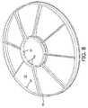
- FIGURE 1illustrates such a spherical matching layer 10.
- the concave surface 12is the emitting surface of the finished transducer which faces the patient and the convex surface 14 is sputtered to produce a redundant signal return electrode, then covered with composite piezoelectric tiles.
- the rigid matching layerthus provides a form of the desired curvature for assembly of the piezoelectric tile layer. Since the matching layer 10 in front of the tiles is a continuously formed surface, it provides the desired electrical and moisture-impervious environmental isolation of the electrical elements of the HIFU transducer from the patient and the external surroundings in front of the HIFU transducer.
- Construction of the composite piezoelectric transducer arraybegins with a sheet 30 of ceramic piezoelectric material as shown in FIGURES 2a and 2b .
- the sheet 30is 1.2mm thick (T).
- a number of holesare drilled through the sheet 30 where it is desired to have electrical connections from the back to the front (emitting side) of the transducer.
- the holesare then filled with silver-filled epoxy to form vias 32 through the sheet.
- the silver fillingprovides electrical conductivity and is non-magnetic for operation in a magnetic field of an MRI system. Other non-magnetic conductive material may be used for the conductive filling.
- the silver epoxyis cured.
- the sheetis then diced part-way through the thickness with parallel cuts 16 in one direction as shown in the view of the edge of the sheet 30 in FIGURE 2a . Then the sheet is diced part-way through with parallel cuts in the orthogonal direction, leaving a plurality of upward projecting piezoelectric posts 18 and vias 32. The dicing cuts are then filled with non-conducting epoxy and cured. The top and bottom surfaces of the sheet are then machined flat to the depths indicated by dashed lines 34 in FIGURE 2a . This will result in a finished sheet of a matrix of piezoelectric posts 18 and conductive vias 32 in epoxy 36 as shown in FIGURE 2b .
- the finished sheetcomprises a 1:3 matrix of piezoelectric posts, each of which has its dominant vibrational mode in its longitudinal direction through the thickness of the sheet, and which transmits ultrasound predominately in a direction toward the front (patient facing) side of the transducer.
- This predominant vibrational mode of the composite materialreduces unwanted lateral transmission across the array to other active areas of the array.
- the flat composite piezoelectric sheet 30is machined to a trapezoidal shape as shown by the peripheral shape of the composite piezoelectric tile 40 of FIGURE 4 .
- the tileshave the trapezoidal shape of FIGURE 4 to allow for a circular spherical center tile as described below.
- each tilemay be machined in the shape of a slice of pie, so that the tiles will cover the matching layer without need for a center tile.
- the tilescould also take on other geometric shapes arranged to cover the spherical surface including but not limited to pentagons mixed with hexagons as demonstrated by the panels of a soccer ball.
- the flat trapezoidal tile of FIGURE 4is then given its desired spherical curvature.
- the tilecan be heated to soften the epoxy so that the tile can be conformed to the desired curvature. This can be done by placing the tile 40 on a heated concave or convex fixture, then pressing the tile into conformance with the convex or concave shape. While the tile is held in the desired curvature, the fixture is cooled and the epoxy is allowed to fully cure. The result is a spherical-shaped composite piezoelectric tile for a spherical HIFU transducer.
- the top and bottom surfaces 38are metallized by sputtering a conductive material onto the surfaces of the sheet as shown for the sheet 30 of FIGURE 3 .
- the conductive materialis non-magnetic such as gold or titanium/gold.
- the metallized surfacesare electrically connected by the conductive vias 32, providing electrical connection from the back surface of the composite sheet to the front.
- Active (transmitting and receiving) areas of the composite piezoelectric sheetare then isolated by diamond core drilling, laser drilling, or ultrasonic machining around desired active areas from the back (convex) surface of the tile. Several such defined active areas 44 are shown in FIGURES 3 and 4 .
- the cuts 42which define the active areas cut through the metallization of the surface of the sheet to electrically isolate the areas and preferably extend over half-way through the composite sheet so as to acoustically isolate the active area from the surrounding areas of the sheet and other active areas.
- the active areascan be electrically and acoustically isolated after the tiles are bonded to the matching layer.
- the active areas 44are not symmetrically arranged in rows or columns or circles or other regular patterns but are irregularly or randomly arranged as shown in FIGURE 4 .
- the random patternprevents any significant additive combining of the acoustic sidelobes of the active areas which would diminish the effective energy delivered by the HIFU transducer.
- Eight of the spherical trapezoidal tiles 40are then thin bonded adjacent to each other around the convex surface 14 of the matching layer 10, which thereby provides a form for assembly of the tiles. If the spherical tiles 40 are pie-shaped as described above, the tiles will completely cover the convex side of the matching layer 10. When the spherical tiles are trapezoidal as shown in FIGURE 4 , they will cover the convex side of the matching layer except for the center of the matching layer. This circular spherical space can be left open. Alternatively it can be covered with a circular spherical thermal conductor such as aluminum for cooling.
- a thermal conductorhere can aid in cooling the HIFU transducer.
- a circular spherical composite piezoelectric tile 48can fill this space.
- the circular sheet of FIGURE 3with its own active areas, can be formed into a spherical shape and located here, providing full composite piezoelectric coverage of the matching layer 10 as shown by the cross-sectional view of the trapezoidal and circular tiles on the matching layer 10 in FIGURE 5 .
- the nine tilesprovide the HIFU transducer with 265 active areas, 256 for transmit and nine for receive.
- the vias 32are located so as to connect the metallized area around the active areas on the back surface to the metallized surface on the front (patient-facing) side of the tile.
- the metallized area around the active areas 44is electrically coupled to a reference potential.
- the vias 32couple this reference potential to the metallized surface on the other side of the tile, the side not visible in FIGURE 3 .
- the viasare thus used to apply a reference potential to the patient-facing side of the composite piezoelectric tiles, and also to the metallization on the patient-facing side of the active areas 44. Since the patient-facing side of the tiles 40 are bonded to the matching layer 10 and are thus inaccessible for electrical connections, the vias provide the needed electrical connection through the piezoelectric sheet to the front side of the tile.
- a plastic support frame 50is attached to the back of the assembled tiles by bonding, snap fit, or fasteners as shown in FIGURE 6 .
- each of the nine tiles 40,48is accessible between the ribs of the support frame.
- the support frameis used to mount eight trapezoidal and one circular printed circuit boards 52 in a spaced relation above the back surfaces of the composite piezoelectric tiles 40.
- FIGURES 7a and 7billustrate the front and back (54) surfaces of the trapezoidal printed circuit boards 52.
- Located on the back surface 54are printed circuit connections 56 from a connector 57 which are connected by plated through-holes 59 through the board to active areas of the HIFU transducer.
- compliant metallic contacts 60which span the space between a printed circuit board and its tile and electrically connect the printed circuit connections to the active areas 44 and vias 32 of the opposing composite piezoelectric tile 40.
- cooling notches 58Located at one edge of the printed circuit board 52 which is at the periphery of the HIFU transducer are cooling notches 58.
- a printed circuit board 52is bonded to the support frame 50 above each tile such as tile 40 shown in FIGURE 6 .
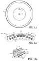
- a printed circuit boardis assembled in this manner it appears as shown by printed circuit board 52 in FIGURE 8 .
- the extended ends of the compliant metallic contacts 60are coated with conductive epoxy.
- the ends of the contacts 60will contact metallized areas of the opposing tile and become bonded in electrical connection with the metallized areas when the conductive epoxy cures.
- the contacts 60thus provide electrical communication between the printed circuit boards and active and reference potential areas of the piezoelectric tiles.
- the printed circuit board 52 of FIGURES 7a and 7bpreferably have a spherical curvature, matching that of the opposing composite piezoelectric tiles 40 to which they are connected by the contacts 60.
- the printed circuit boardscan be curved on just the side facing the tile as shown in FIGURE 7a , or on both sides.
- the printed circuit boardscan be formed as curved boards in several ways. One is to start with a thick planar sheet of glass epoxy board material and machine or grind the surface of the board to the desired curvature. The other technique is to use thermoforming to heat the board material and soften the epoxy, then form the curvature by compressing the sheet against a fixture of the desired curvature.
- the circuit boardscan be double-clad with photo-imaged and chemically-etched conductive lines on the top and bottom surfaces interconnected by plated through-holes formed in the boards.
- the circuit boardscan also be multilayer boards with three or more layers of conductive lines formed on the surfaces and within layers of the board for more complex, higher density circuit configurations.
- the rigid boards 52are also capable of securely mounting other electrical components such as the connector 57.
- the compliant metallic contacts 60may be formed as springs, such as leaf springs, curled springs, or helical springs.
- the springsprovide numerous benefits. First, they provide electrical connection from the printed circuit boards to provide drive signals and reference potential to areas of the piezoelectric of the HIFU transducer. When a flat, planar printed circuit board is used in opposition to a spherically shaped composite piezoelectric tile, the compliance of the contacts 60 will allow the contacts to span the uneven distance 62 between the board 52 and the piezoelectric tile, being relatively uncompressed when the spanned distance is greater and relatively more compressed when the distance is less. Second, they allow a space 62 to remain between the piezoelectric tiles which is used for cooling the piezoelectric tiles.
- the metallic contactsare thermally conductive and span the air flow passageway between the piezoelectric material and the printed circuit board, they will conduct heat from the piezoelectric material which will be dissipated as air flows past the contacts in the passageway.
- This active transducer area 44is isolated from the surrounding area of the tile by cuts 42 through the surface metallization and into the composite piezoelectric tile 40.
- On either side of the center contact 60are spring clip contacts 60a which are connected to the metallization above vias 32. These electrical connections thereby connect the front metallized surface of the tile, that which is bonded to the matching layer 10 and is therefore inaccessible for direct electrical connection, to a desired electrical potential such as a reference potential.
- FIGURE 10illustrates further assembly of a HIFU transducer of the present invention in which the assembled matching layer 10, composite piezoelectric tiles 40, support frame 50 and printed circuit boards 52 are fit into a circular peripheral frame 80 which is capped with a back plate 70.
- the back plate 70thereby encloses an air passageway 76 between the back surfaces of the printed circuit boards 52 and the plate.
- the back plateincludes two air ports 72 and 74, one accessing the cooling space 62' between the center printed circuit board 52' and the center piezoelectric tile through a hole in the board 52', and the other accessing the air passageway 76 between the boards 52 and the plate 70.
- the back plate 70is shown in a plan view in FIGURE 11 .
- the plate 70contacts the circular central rib of the support frame 50 to separate the cooling space 62' from the peripheral air passageway 76. Air for cooling is forced into one of these ports and out the other to cool the composite piezoelectric tiles 40.
- the composite piezoelectric tileshave no backing material attached to their back (non-emitting) surfaces. Instead, they are backed by the cooling space 62. This means that there is no attached backing material to be heated by the composite piezoelectric during use. Instead, the back surface of the composite piezoelectric is cooled by the flow of air in the cooling space 62 between the composite piezoelectric and the printed circuit boards 52.
- the airWhen air is forced into the port 74, for instance, the air will flow through the central cooling space 62', through apertures 64 in the support frame 50 (see FIGURE 8 ), through the cooling spaces 62 between the trapezoidal tiles 40 and the trapezoidal printed circuit boards 52, through the peripheral notches 58 of the printed circuit boards into the air passageway 76, and out through the port 72.
- the back surface of the composite piezoelectric tilescan be continuously directly air-cooled during use of the HIFU transducer.
- FIGURE 12is a cross-sectional view through the center of the HIFU transducer assembly of FIGURE 10 which further illustrates the elements of the air cooling system of the assembly.
- FIGURE 12ais an enlarged view of the periphery of the assembly, showing a piezoelectric tile 40, support frame 50 and printed circuit board 52 in abutment with the peripheral frame 80 and capped with the back plate 70.
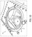
- FIGURE 13illustrates a HIFU transducer 22 of the present invention employed in the patient support table 28 of an ultrasonic HIFU system 20.
- FIGURE 13presents a top view of the patient support table.
- the patient support table 28has a first reservoir 24 filled with a suitable transmission liquid, for example, water.
- a suitable transmission liquidfor example, water.
- the HIFU transducer 22is located in the first reservoir 24 and is arranged to emit high intensity focused ultrasonic energy upward toward a patient reclined on the table 28.
- the water of the reservoir 24provides an acoustic coupling medium between the HIFU transducer 22 and the patient, and also provides cooling of the front of the HIFU transducer.
- a second reservoir 27comprising a low reflective medium is positioned above the first reservoir 24.
- a suitable gel padis used for the second reservoir.
- the second reservoir 27comprises a contact surface 27a onto which a patient to be treated is positioned.
- the apparatus 20further comprises an aperture 26 arranged to enable an inspection, for example, a visual inspection, of the contact surface 27a between the second reservoir 27 and the patient.
- the aperture 26is preferably arranged as a substantially transparent window through which medical personnel directly, or using a mirror or a suitably arranged camera, can inspect for the presence of air bubbles between the contact surface 27a and the patient.
- the patientis repositioned until no air bubbles are present. After that, the patient is suitably immobilized and a treatment may be commenced.
- the HIFU system 20 of FIGURE 13is further described in international patent application publication number WO 2008/102293 (Bruggers).
Landscapes
- Engineering & Computer Science (AREA)
- Mechanical Engineering (AREA)
- Physics & Mathematics (AREA)
- Acoustics & Sound (AREA)
- Multimedia (AREA)
- Transducers For Ultrasonic Waves (AREA)
- Ultra Sonic Daignosis Equipment (AREA)
- Surgical Instruments (AREA)
Description
- This invention relates to medical diagnostic ultrasound systems and, in particular, to ultrasonic transducers which are used for controlled heating of body tissues by high intensity focused ultrasound, known as HIFU.
- Ultrasonically delivered elevated temperature treatments are used for a variety of therapeutic purposes In HIFU treatment, ultrasonic energy is focused to a small spot within the body so as to heat the tissues to a temperature sufficient to create a desired therapeutic effect. The technique is similar to lithotripsy, where focused energy is high enough to break up kidney stones, but with considerably less energy that is delivered over an extended time rather than a sudden pulse. The HIFU technique can be used to selectively destroy unwanted tissue within the body. For example, tumors or other pathological tissues can be destroyed by applying focused ultrasonic energy so as to heat the cells to a temperature sufficient to kill the tissue, generally about 60 to about 80 degrees C., without destroying adjacent normal tissues. Other elevated-temperature treatments include selectively heating tissues so as to selectively activate a drug or to promote some other physiological change in a selected portion of the subject's body.
- HIFU transducers are often formed as spherical or parabolic dishes with a radius of curvature that gives the transducer a geometric focal point. See, for example, the HIFU transducer described in international patent application publication number
WO 98/52465 (Acker et al. - A significant number of transducer sections are needed to provide the high energy to be delivered by the transducer. The transducer of the Acker et al. publication is about 15 cm in diameter and has many transducer sections attached to its dish-shaped frame. Accurate placement of the transducer sections on the frame is needed to give the final assembly its desired spherical shape and acoustical properties. This poses a significant fabrication and construction effort and requires painstaking quality control and testing to verify that each section is fully operational.
- From
US 5,743,862 an ultrasonic medical treatment apparatus is known including a concave piezoelectric oscillator. The concave piezoelectric oscillator comprises a plurality of piezoelectric oscillation plates having equal areas. Each piezoelectric oscillation plate comprises a plurality of piezoelectric oscillator elements. Each piezoelectric oscillator element has a higher resonance frequency in the lateral direction thereof than in the thickness direction thereof. WO 02/063606 A1 - Accordingly it would be desirable to provide a transducer structure that can be more easily formed into its desired shape, and preferably using components which play a role in the acoustic performance of the spherical transducer.
- In accordance with the principles of the present invention, a spherical HIFU transducer is described which is formed of a plurality of composite ceramic piezoelectric tiles fitted around a pre-formed spherical matching layer. The matching layer is separately formed in advance of assembly of the transducer with the piezoelectric tiles then using the matching layer as a form for assembly of the spherical transducer. The matching layer is formed as a continuous body which provides electrical and
environmental isolation between the piezoelectric elements and the front emitting side of the transducer. - In the drawings:
FIGURE 1 illustrates in perspective a spherical transducer matching layer separately formed for a HIFU transducer of the present invention.FIGURE 2a illustrates an end view of a sheet of ceramic piezoelectric material which has been diced to form a composite transducer array for a HIFU transducer of the present invention.FIGURE 2b illustrates a composite transducer array with a nonmagnetic via constructed in accordance with the principles of the present invention.FIGURE 3 illustrates a composite transducer array with emitting elements and nonmagnetic vias constructed in accordance with the principles of the present invention.FIGURE 4 illustrates a composite piezoelectric tile prior to spherical shaping for a HIFU transducer of the present invention.FIGURE 5 illustrates in cross-section the placement of composite piezoelectric tiles on the matching layer for a HIFU transducer of the present invention.FIGURE 6 illustrates in perspective the back of a nine-tile HIFU transducer of the present invention.FIGURES 7a and 7b illustrate the front and back surfaces of a curved printed circuit board with extended compliant contacts for a HIFU transducer of the present invention.FIGURE 8 illustrates in perspective the back of a HIFU transducer of the present invention with a support frame attached for the printed circuit boards ofFIGURES 7a and 7b .FIGURE 9 is a detailed illustration of the connection of the extended compliant contacts of a printed circuit board to transducer areas of a HIFU transducer of the present invention.FIGURE 10 is a partial cross-sectional and perspective view of a HIFU transducer of the present invention with a peripheral frame and back duct cover.FIGURE 11 is a plan view of the back duct cover ofFIGURE 10 .FIGURE 12 is a cross-sectional view of the HIFU transducer ofFIGURE 10 .FIGURE 12a is an enlarged view of the periphery of the HIFU transducer ofFIGURE 12 .FIGURE 13 is a perspective view of a HIFU transducer of the present invention when mounted in a patient support table.- Construction of a HIFU transducer of the present invention may begin with fabrication of a spherical or dish-shaped matching layer. The matching layer(s) of a transducer provide at least a partial matching of the acoustic properties of the piezoelectric transducer to the acoustic properties of the patient's body or the medium between the transducer and the patient. The properties matched may include acoustic impedance, velocity of sound, and material density. In the conventional construction of an ultrasound transducer the matching layer is generally formed on the transducer stack and is formed over the reference electrodes on the emitting surface of the piezoelectric material. For the HIFU transducer described in this disclosure a spherical matching layer is formed by itself, separate from the rest of the transducer. There are several ways to form the spherical matching layer, including casting, molding, thermoforming, or machining. The spherical matching layer of the HIFU transducer described herein is made of a loaded epoxy which is loaded with particles which provide the matching layer with its desired acoustic properties as is known in the art. Preferably the particles are non-magnetic. In casting or molding the spherical matching layer, the loaded epoxy is poured into a concave fixture of the desired spherical shape. A convex fixture is closed over the concave fixture, forcing the liquid epoxy to fill the spherical space between the two fixtures. The epoxy is cured and removed from the fixtures, then peripherally machined to its final form. In a thermoform process a planar sheet of the desired thickness is formed of the loaded epoxy, then partially cured. The sheet is then placed over a heated convex or concave fixture of the desired curvature which warms the sheet so that it becomes pliant and conforms to the curvature of the fixture. When the sheet has attained its desired spherical shape it is cured and finished. In a machining process a disk of loaded epoxy is cast or molded and cured. The disk is then machined on one side to form a convex surface. The disk is then put on a concave fixture and the other side of the disk is machined to form the concave side of the spherical matching layer. In a constructed embodiment the finished spherical matching layer from any of these processes is 0.5mm thick, has a diameter of 140mm, and a spherical radius of 140mm, the size and shape of the finished HIFU transducer.
FIGURE 1 illustrates such aspherical matching layer 10. Theconcave surface 12 is the emitting surface of the finished transducer which faces the patient and theconvex surface 14 is sputtered to produce a redundant signal return electrode, then covered with composite piezoelectric tiles. The rigid matching layer thus provides a form of the desired curvature for assembly of the piezoelectric tile layer. Since thematching layer 10 in front of the tiles is a continuously formed surface, it provides the desired electrical and moisture-impervious environmental isolation of the electrical elements of the HIFU transducer from the patient and the external surroundings in front of the HIFU transducer. - Construction of the composite piezoelectric transducer array begins with a
sheet 30 of ceramic piezoelectric material as shown inFIGURES 2a and 2b . In a constructed transducer thesheet 30 is 1.2mm thick (T). First, a number of holes are drilled through thesheet 30 where it is desired to have electrical connections from the back to the front (emitting side) of the transducer. The holes are then filled with silver-filled epoxy to formvias 32 through the sheet. The silver filling provides electrical conductivity and is non-magnetic for operation in a magnetic field of an MRI system. Other non-magnetic conductive material may be used for the conductive filling. The silver epoxy is cured. The sheet is then diced part-way through the thickness withparallel cuts 16 in one direction as shown in the view of the edge of thesheet 30 inFIGURE 2a . Then the sheet is diced part-way through with parallel cuts in the orthogonal direction, leaving a plurality of upward projectingpiezoelectric posts 18 andvias 32. The dicing cuts are then filled with non-conducting epoxy and cured. The top and bottom surfaces of the sheet are then machined flat to the depths indicated by dashedlines 34 inFIGURE 2a . This will result in a finished sheet of a matrix ofpiezoelectric posts 18 andconductive vias 32 inepoxy 36 as shown inFIGURE 2b . The finished sheet comprises a 1:3 matrix of piezoelectric posts, each of which has its dominant vibrational mode in its longitudinal direction through the thickness of the sheet, and which transmits ultrasound predominately in a direction toward the front (patient facing) side of the transducer. This predominant vibrational mode of the composite material reduces unwanted lateral transmission across the array to other active areas of the array. - The flat composite
piezoelectric sheet 30 is machined to a trapezoidal shape as shown by the peripheral shape of the compositepiezoelectric tile 40 ofFIGURE 4 . In a constructed HIFU transducer the tiles have the trapezoidal shape ofFIGURE 4 to allow for a circular spherical center tile as described below. Alternatively, each tile may be machined in the shape of a slice of pie, so that the tiles will cover the matching layer without need for a center tile. The tiles could also take on other geometric shapes arranged to cover the spherical surface including but not limited to pentagons mixed with hexagons as demonstrated by the panels of a soccer ball. The flat trapezoidal tile ofFIGURE 4 is then given its desired spherical curvature. Since the composite transducer is formed of a matrix in epoxy, the tile can be heated to soften the epoxy so that the tile can be conformed to the desired curvature. This can be done by placing thetile 40 on a heated concave or convex fixture, then pressing the tile into conformance with the convex or concave shape. While the tile is held in the desired curvature, the fixture is cooled and the epoxy is allowed to fully cure. The result is a spherical-shaped composite piezoelectric tile for a spherical HIFU transducer. - After the tile has been curved the top and
bottom surfaces 38 are metallized by sputtering a conductive material onto the surfaces of the sheet as shown for thesheet 30 ofFIGURE 3 . Preferably the conductive material is non-magnetic such as gold or titanium/gold. The metallized surfaces are electrically connected by theconductive vias 32, providing electrical connection from the back surface of the composite sheet to the front. Active (transmitting and receiving) areas of the composite piezoelectric sheet are then isolated by diamond core drilling, laser drilling, or ultrasonic machining around desired active areas from the back (convex) surface of the tile. Several such definedactive areas 44 are shown inFIGURES 3 and 4 . Thecuts 42 which define the active areas cut through the metallization of the surface of the sheet to electrically isolate the areas and preferably extend over half-way through the composite sheet so as to acoustically isolate the active area from the surrounding areas of the sheet and other active areas. Alternatively, the active areas can be electrically and acoustically isolated after the tiles are bonded to the matching layer. - In a constructed tile the
active areas 44 are not symmetrically arranged in rows or columns or circles or other regular patterns but are irregularly or randomly arranged as shown inFIGURE 4 . The random pattern prevents any significant additive combining of the acoustic sidelobes of the active areas which would diminish the effective energy delivered by the HIFU transducer. - Eight of the spherical
trapezoidal tiles 40 are then thin bonded adjacent to each other around theconvex surface 14 of thematching layer 10, which thereby provides a form for assembly of the tiles. If thespherical tiles 40 are pie-shaped as described above, the tiles will completely cover the convex side of thematching layer 10. When the spherical tiles are trapezoidal as shown inFIGURE 4 , they will cover the convex side of the matching layer except for the center of the matching layer. This circular spherical space can be left open. Alternatively it can be covered with a circular spherical thermal conductor such as aluminum for cooling. Returning acoustic energy will tend to be focused in the center of the HIFU transducer by virtue of its spherical geometric shape. Locating a thermal conductor here can aid in cooling the HIFU transducer. Alternatively, a circular spherical compositepiezoelectric tile 48 can fill this space. For example, the circular sheet ofFIGURE 3 , with its own active areas, can be formed into a spherical shape and located here, providing full composite piezoelectric coverage of thematching layer 10 as shown by the cross-sectional view of the trapezoidal and circular tiles on thematching layer 10 inFIGURE 5 . In a constructed transducer of this full coverage design, the nine tiles provide the HIFU transducer with 265 active areas, 256 for transmit and nine for receive. - It is seen in
FIGURE 3 that thevias 32 are located so as to connect the metallized area around the active areas on the back surface to the metallized surface on the front (patient-facing) side of the tile. In a constructed HIFU transducer the metallized area around theactive areas 44 is electrically coupled to a reference potential. Thevias 32 couple this reference potential to the metallized surface on the other side of the tile, the side not visible inFIGURE 3 . The vias are thus used to apply a reference potential to the patient-facing side of the composite piezoelectric tiles, and also to the metallization on the patient-facing side of theactive areas 44. Since the patient-facing side of thetiles 40 are bonded to thematching layer 10 and are thus inaccessible for electrical connections, the vias provide the needed electrical connection through the piezoelectric sheet to the front side of the tile. - Next, a
plastic support frame 50 is attached to the back of the assembled tiles by bonding, snap fit, or fasteners as shown inFIGURE 6 . In a constructed transducer each of the ninetiles circuit boards 52 in a spaced relation above the back surfaces of the compositepiezoelectric tiles 40.FIGURES 7a and 7b illustrate the front and back (54) surfaces of the trapezoidal printedcircuit boards 52. Located on theback surface 54 are printedcircuit connections 56 from aconnector 57 which are connected by plated through-holes 59 through the board to active areas of the HIFU transducer. On the front surface of the printed circuit boards are compliantmetallic contacts 60 which span the space between a printed circuit board and its tile and electrically connect the printed circuit connections to theactive areas 44 and vias 32 of the opposing compositepiezoelectric tile 40. Located at one edge of the printedcircuit board 52 which is at the periphery of the HIFU transducer are coolingnotches 58. - A printed
circuit board 52 is bonded to thesupport frame 50 above each tile such astile 40 shown inFIGURE 6 . When a printed circuit board is assembled in this manner it appears as shown by printedcircuit board 52 inFIGURE 8 . Before this assembly, the extended ends of the compliantmetallic contacts 60 are coated with conductive epoxy. When the printed circuit board is assembled on the frame, the ends of thecontacts 60 will contact metallized areas of the opposing tile and become bonded in electrical connection with the metallized areas when the conductive epoxy cures. Thecontacts 60 thus provide electrical communication between the printed circuit boards and active and reference potential areas of the piezoelectric tiles. - While the printed circuit boards can be fabricated as conventional planar printed circuit boards, the printed
circuit board 52 ofFIGURES 7a and 7b preferably have a spherical curvature, matching that of the opposing compositepiezoelectric tiles 40 to which they are connected by thecontacts 60. The printed circuit boards can be curved on just the side facing the tile as shown inFIGURE 7a , or on both sides. The printed circuit boards can be formed as curved boards in several ways. One is to start with a thick planar sheet of glass epoxy board material and machine or grind the surface of the board to the desired curvature. The other technique is to use thermoforming to heat the board material and soften the epoxy, then form the curvature by compressing the sheet against a fixture of the desired curvature. The circuit boards can be double-clad with photo-imaged and chemically-etched conductive lines on the top and bottom surfaces interconnected by plated through-holes formed in the boards. The circuit boards can also be multilayer boards with three or more layers of conductive lines formed on the surfaces and within layers of the board for more complex, higher density circuit configurations. Therigid boards 52 are also capable of securely mounting other electrical components such as theconnector 57. - The compliant
metallic contacts 60 may be formed as springs, such as leaf springs, curled springs, or helical springs. The springs provide numerous benefits. First, they provide electrical connection from the printed circuit boards to provide drive signals and reference potential to areas of the piezoelectric of the HIFU transducer. When a flat, planar printed circuit board is used in opposition to a spherically shaped composite piezoelectric tile, the compliance of thecontacts 60 will allow the contacts to span theuneven distance 62 between theboard 52 and the piezoelectric tile, being relatively uncompressed when the spanned distance is greater and relatively more compressed when the distance is less. Second, they allow aspace 62 to remain between the piezoelectric tiles which is used for cooling the piezoelectric tiles. Third, they provide compliant electrical connections which allow for the spacing between the printed circuit boards and the tiles to change with heating and cooling of the HIFU transducer. Fourth, since the metallic contacts are thermally conductive and span the air flow passageway between the piezoelectric material and the printed circuit board, they will conduct heat from the piezoelectric material which will be dissipated as air flows past the contacts in the passageway. These benefits can be appreciated from the enlarged view of these connections ofFIGURE 9 . In this drawing thecontacts 60 are formed as spring clips which span the coolingspace 62 between the printedcircuit board 52 and thetile 40. Thecenter contact 60 is seen to be providing electrical connection to anactive area 44 of thetile 40. Thisactive transducer area 44 is isolated from the surrounding area of the tile bycuts 42 through the surface metallization and into the compositepiezoelectric tile 40. On either side of thecenter contact 60 arespring clip contacts 60a which are connected to the metallization abovevias 32. These electrical connections thereby connect the front metallized surface of the tile, that which is bonded to thematching layer 10 and is therefore inaccessible for direct electrical connection, to a desired electrical potential such as a reference potential. FIGURE 10 illustrates further assembly of a HIFU transducer of the present invention in which the assembledmatching layer 10, compositepiezoelectric tiles 40,support frame 50 and printedcircuit boards 52 are fit into a circularperipheral frame 80 which is capped with aback plate 70. Theback plate 70 thereby encloses anair passageway 76 between the back surfaces of the printedcircuit boards 52 and the plate. The back plate includes twoair ports air passageway 76 between theboards 52 and theplate 70. Theback plate 70 is shown in a plan view inFIGURE 11 . In the example ofFIGURE 10 theplate 70 contacts the circular central rib of thesupport frame 50 to separate the cooling space 62' from theperipheral air passageway 76. Air for cooling is forced into one of these ports and out the other to cool the compositepiezoelectric tiles 40. It is seen that, unlike a conventional transducer stack, the composite piezoelectric tiles have no backing material attached to their back (non-emitting) surfaces. Instead, they are backed by the coolingspace 62. This means that there is no attached backing material to be heated by the composite piezoelectric during use. Instead, the back surface of the composite piezoelectric is cooled by the flow of air in the coolingspace 62 between the composite piezoelectric and the printedcircuit boards 52. When air is forced into theport 74, for instance, the air will flow through the central cooling space 62', throughapertures 64 in the support frame 50 (seeFIGURE 8 ), through the coolingspaces 62 between thetrapezoidal tiles 40 and the trapezoidal printedcircuit boards 52, through theperipheral notches 58 of the printed circuit boards into theair passageway 76, and out through theport 72. Thus, the back surface of the composite piezoelectric tiles can be continuously directly air-cooled during use of the HIFU transducer.FIGURE 12 is a cross-sectional view through the center of the HIFU transducer assembly ofFIGURE 10 which further illustrates the elements of the air cooling system of the assembly.FIGURE 12a is an enlarged view of the periphery of the assembly, showing apiezoelectric tile 40,support frame 50 and printedcircuit board 52 in abutment with theperipheral frame 80 and capped with theback plate 70.FIGURE 13 illustrates aHIFU transducer 22 of the present invention employed in the patient support table 28 of anultrasonic HIFU system 20.FIGURE 13 presents a top view of the patient support table. The patient support table 28 has afirst reservoir 24 filled with a suitable transmission liquid, for example, water. For reasons of clarity, the transparent membrane sealing the top of thefirst reservoir 24 is not shown. TheHIFU transducer 22 is located in thefirst reservoir 24 and is arranged to emit high intensity focused ultrasonic energy upward toward a patient reclined on the table 28. The water of thereservoir 24 provides an acoustic coupling medium between theHIFU transducer 22 and the patient, and also provides cooling of the front of the HIFU transducer. In order to complete the coupling of the ultrasonic energy emanating from the first reservoir to the patient, asecond reservoir 27 comprising a low reflective medium is positioned above thefirst reservoir 24. Preferably, a suitable gel pad is used for the second reservoir. Thesecond reservoir 27 comprises acontact surface 27a onto which a patient to be treated is positioned. Theapparatus 20 further comprises anaperture 26 arranged to enable an inspection, for example, a visual inspection, of thecontact surface 27a between thesecond reservoir 27 and the patient. Theaperture 26 is preferably arranged as a substantially transparent window through which medical personnel directly, or using a mirror or a suitably arranged camera, can inspect for the presence of air bubbles between thecontact surface 27a and the patient. In the case when an air bubble is detected, the patient is repositioned until no air bubbles are present. After that, the patient is suitably immobilized and a treatment may be commenced. TheHIFU system 20 ofFIGURE 13 is further described in international patent application publication numberWO 2008/102293 (Bruggers).
Claims (10)
- A curved high intensity focused ultrasound (HIFU) transducer comprising:a curved piezoelectric array having opposite convex and concave surfaces, wherein the piezoelectric array is formed of a plurality of piezoelectric tiles (40), the concave surface being a transmitting surface, and a plurality of acoustic transmission areas;characterized in that it further comprises:a plurality of electrodes located on the surfaces of the curved piezoelectric array for applying electrical transmit signals to the acoustic transmission areas (44);a unitary, continuously formed curved matching layer (10) preformed to the desired curvature of the curved transducer array and bonded to the transmitting surface of the curved piezoelectric array which provides acoustic matching and electrical isolation for the transmitting surface of the curved piezoelectric array;a support frame (50) attached to the convex surface; anda plurality of printed circuit boards (52) each associated to one of the piezoelectric tiles, wherein the printed circuit boards are mounted in a spaced relation above a back surface of the piezoelectric tiles by means of the support frame (50), wherein each printed circuit board is electrically connected to active areas of the respective piezoelectric tile by means of compliant metallic contacts, which span a space between the printed circuit board and the piezoelectric tiles.
- The curved HIFU transducer of Claim 1, wherein the matching layer (10) further comprises a spherically-curved layer formed by casting or molding.
- The curved HIFU transducer of Claim 1, wherein the matching layer (10) further comprises a spherically-curved layer formed by machining a solid matching layer material.
- The curved HIFU transducer of Claim 1, wherein the curved matching layer (10) comprises an epoxy loaded with particles which give the matching layer a desired acoustic property.
- The curved HIFU transducer of Claim 1, wherein the curved matching layer (10) comprises a thermoplastic resin loaded with particles which give the matching layer a desired acoustic property.
- The curved HIFU transducer of Claim 1, wherein the pre-formed matching layer (10) further comprises a fixture onto which the piezoelectric tiles (40) are assembled together and bonded.
- The curved HIFU transducer of Claim 6, wherein each piezoelectric tile further exhibits a partially spherical concave surface,
wherein the partially spherical concave surfaces conform to a convex surface of the pre-formed matching layer (10). - The curved HIFU transducer of Claim 1, wherein the matching layer (10) further comprises a continuous, moisture-impervious barrier between the curved piezoelectric array and the environment in front of the transducer.
- The curved HIFU transducer of Claim 1, wherein the matching layer (10) further comprises a continuous, electrically-insulating barrier between the curved piezoelectric array and the environment in front of the transducer.
- The curved HIFU transducer of Claim 1, wherein the surface of the matching layer (10) which is bonded to the curved piezoelectric array comprises a convex surface, wherein the convex surface of the matching layer is covered by a metallized electrode.
Applications Claiming Priority (2)
| Application Number | Priority Date | Filing Date | Title |
|---|---|---|---|
| US25930109P | 2009-11-09 | 2009-11-09 | |
| PCT/IB2010/054982WO2011055313A1 (en) | 2009-11-09 | 2010-11-03 | Curved ultrasonic hifu transducer with pre-formed spherical matching layer |
Publications (2)
| Publication Number | Publication Date |
|---|---|
| EP2498920A1 EP2498920A1 (en) | 2012-09-19 |
| EP2498920B1true EP2498920B1 (en) | 2016-09-14 |
Family
ID=43500975
Family Applications (1)
| Application Number | Title | Priority Date | Filing Date |
|---|---|---|---|
| EP10785212.1AActiveEP2498920B1 (en) | 2009-11-09 | 2010-11-03 | Curved ultrasonic hifu transducer with pre-formed spherical matching layer |
Country Status (7)
| Country | Link |
|---|---|
| US (1) | US10189053B2 (en) |
| EP (1) | EP2498920B1 (en) |
| JP (1) | JP5750114B2 (en) |
| CN (1) | CN102596432B (en) |
| BR (1) | BR112012010614B1 (en) |
| RU (1) | RU2553496C2 (en) |
| WO (1) | WO2011055313A1 (en) |
Families Citing this family (29)
| Publication number | Priority date | Publication date | Assignee | Title |
|---|---|---|---|---|
| US9282945B2 (en) | 2009-04-14 | 2016-03-15 | Maui Imaging, Inc. | Calibration of ultrasound probes |
| US9788813B2 (en) | 2010-10-13 | 2017-10-17 | Maui Imaging, Inc. | Multiple aperture probe internal apparatus and cable assemblies |
| US10226234B2 (en) | 2011-12-01 | 2019-03-12 | Maui Imaging, Inc. | Motion detection using ping-based and multiple aperture doppler ultrasound |
| JP6274724B2 (en) | 2010-02-18 | 2018-02-07 | マウイ イマギング,インコーポレーテッド | Point source transmission and sound velocity correction using multi-aperture ultrasound imaging |
| KR101906838B1 (en) | 2010-10-13 | 2018-10-11 | 마우이 이미징, 인코포레이티드 | Concave ultrasound transducers and 3d arrays |
| JP5605567B2 (en)* | 2010-12-03 | 2014-10-15 | 国立大学法人東北大学 | Array type ultrasonic transmitter |
| FR2984066B1 (en)* | 2011-12-07 | 2014-05-30 | Imasonic | ULTRASONIC TRANSDUCER WITH ACTIVE ELEMENT SUPPORTED |
| JP2015503404A (en) | 2011-12-29 | 2015-02-02 | マウイ イマギング,インコーポレーテッド | Arbitrary path M-mode ultrasound imaging |
| ES2375857B1 (en)* | 2012-01-13 | 2012-09-12 | Universitat Ramón Llull Fundació Privada | OMNIDIRECTIONAL SOUND SOURCE AND PROCEDURE FOR GENERATING OMNIDIRECTIONAL SOUNDS. |
| JP6438769B2 (en) | 2012-02-21 | 2018-12-19 | マウイ イマギング,インコーポレーテッド | Determination of material hardness using multiple aperture ultrasound. |
| WO2013148673A1 (en) | 2012-03-26 | 2013-10-03 | Maui Imaging, Inc. | Systems and methods for improving ultrasound image quality by applying weighting factors |
| TW201347728A (en)* | 2012-05-17 | 2013-12-01 | Ind Tech Res Inst | Sensing structure for physiological signal, stethoscope therewith and manufacturing method thereof |
| JP6270843B2 (en) | 2012-08-10 | 2018-01-31 | マウイ イマギング,インコーポレーテッド | Calibration of multiple aperture ultrasonic probes |
| WO2014031642A1 (en) | 2012-08-21 | 2014-02-27 | Maui Imaging, Inc. | Ultrasound imaging system memory architecture |
| US20140064513A1 (en) | 2012-09-06 | 2014-03-06 | MUSIC Group IP Ltd. | System and method for remotely controlling audio equipment |
| WO2014160291A1 (en) | 2013-03-13 | 2014-10-02 | Maui Imaging, Inc. | Alignment of ultrasound transducer arrays and multiple aperture probe assembly |
| US9883848B2 (en) | 2013-09-13 | 2018-02-06 | Maui Imaging, Inc. | Ultrasound imaging using apparent point-source transmit transducer |
| CN103706048A (en)* | 2013-12-17 | 2014-04-09 | 南京航空航天大学 | a blood thinner |
| CN106794007B (en) | 2014-08-18 | 2021-03-09 | 毛伊图像公司 | Network-based ultrasound imaging system |
| KR102681141B1 (en) | 2015-03-30 | 2024-07-02 | 마우이 이미징, 인코포레이티드 | Ultrasonic imaging systems and methods for detecting object motion |
| CN108778530B (en) | 2016-01-27 | 2021-07-27 | 毛伊图像公司 | Ultrasound imaging with sparse array detectors |
| WO2019100210A1 (en)* | 2017-11-21 | 2019-05-31 | 深圳先进技术研究院 | Moulding device for spherical ultrasonic transducer and related method |
| TWI704938B (en)* | 2018-12-21 | 2020-09-21 | 財團法人工業技術研究院 | Ultrasonic probe device |
| WO2020203317A1 (en)* | 2019-03-29 | 2020-10-08 | 京セラ株式会社 | Ultrasonic radiation tool and ultrasonic device |
| WO2021131798A1 (en)* | 2019-12-24 | 2021-07-01 | 京セラ株式会社 | Ultrasonic radiation tool and ultrasonic device |
| CN111347221B (en)* | 2020-03-09 | 2021-08-27 | 中科绿谷(深圳)医疗科技有限公司 | Manufacturing process of ultrasonic transducer and ultrasonic transducer |
| CN115007430B (en)* | 2022-05-18 | 2023-09-15 | 中科绿谷(深圳)医疗科技有限公司 | Spherical ultrasonic transducer manufacturing method and ultrasonic transducer |
| CN117019608B (en)* | 2023-10-08 | 2024-01-05 | 中北大学 | High-performance air-coupled ultrasonic point focusing transducer and preparation method thereof |
| CN117589883A (en)* | 2023-10-31 | 2024-02-23 | 东南大学 | A built-in acoustic emission sensor for damage monitoring of pull slings based on flexible film |
Family Cites Families (34)
| Publication number | Priority date | Publication date | Assignee | Title |
|---|---|---|---|---|
| US3732535A (en)* | 1969-08-15 | 1973-05-08 | Raytheon Co | Spherical acoustic transducer |
| US4992692A (en) | 1989-05-16 | 1991-02-12 | Hewlett-Packard Company | Annular array sensors |
| JPH074391B2 (en)* | 1990-05-30 | 1995-01-25 | 株式会社東芝 | Shock wave generator |
| US5423220A (en)* | 1993-01-29 | 1995-06-13 | Parallel Design | Ultrasonic transducer array and manufacturing method thereof |
| JPH06261908A (en)* | 1993-03-15 | 1994-09-20 | Toshiba Corp | Ultrasonic wave transmitter and calculus breaking device equipped with this wave transmitter |
| JP2927144B2 (en)* | 1993-06-23 | 1999-07-28 | 松下電器産業株式会社 | Ultrasonic transducer |
| JPH0871079A (en)* | 1994-09-06 | 1996-03-19 | Toshiba Ceramics Co Ltd | Ultrasonic generator |
| US5743862A (en)* | 1994-09-19 | 1998-04-28 | Kabushiki Kaisha Toshiba | Ultrasonic medical treatment apparatus |
| WO1998052465A1 (en) | 1997-05-23 | 1998-11-26 | Transurgical, Inc. | Mri-guided therapeutic unit and methods |
| US6780505B1 (en) | 1997-09-02 | 2004-08-24 | Ut-Battelle, Llc | Pitch-based carbon foam heat sink with phase change material |
| US6050943A (en)* | 1997-10-14 | 2000-04-18 | Guided Therapy Systems, Inc. | Imaging, therapy, and temperature monitoring ultrasonic system |
| WO2000057495A1 (en) | 1999-03-22 | 2000-09-28 | Transurgical, Inc. | Ultrasonic transducer, transducer array, and fabrication method |
| US6666835B2 (en)* | 1999-05-14 | 2003-12-23 | University Of Washington | Self-cooled ultrasonic applicator for medical applications |
| WO2001045550A2 (en) | 1999-12-23 | 2001-06-28 | Therus Corporation | Ultrasound transducers for imaging and therapy |
| JP4117192B2 (en)* | 2001-02-09 | 2008-07-16 | コーニンクレッカ フィリップス エレクトロニクス エヌ ヴィ | Ultrasonic transducer and method of manufacturing the ultrasonic transducer |
| JP3914002B2 (en) | 2001-04-26 | 2007-05-16 | 日本電波工業株式会社 | Ultrasonic probe |
| US6589180B2 (en)* | 2001-06-20 | 2003-07-08 | Bae Systems Information And Electronic Systems Integration, Inc | Acoustical array with multilayer substrate integrated circuits |
| AU2003219843B2 (en) | 2002-02-20 | 2009-04-23 | Medicis Technologies Corporation | Ultrasonic treatment and imaging of adipose tissue |
| US7117588B2 (en) | 2002-04-23 | 2006-10-10 | Ge Medical Systems Global Technology Company, Llc | Method for assembling tiled detectors for ionizing radiation based image detection |
| JP2004113445A (en)* | 2002-09-26 | 2004-04-15 | Toshiba Corp | Ultrasonic irradiation equipment |
| US8409099B2 (en) | 2004-08-26 | 2013-04-02 | Insightec Ltd. | Focused ultrasound system for surrounding a body tissue mass and treatment method |
| EP1832314B8 (en) | 2004-12-27 | 2023-07-19 | Chengdu Heuk Medical Equipment Co., Ltd | Quasi-self focusing high intensity and large power ultrasonic transducer |
| US20070016039A1 (en)* | 2005-06-21 | 2007-01-18 | Insightec-Image Guided Treatment Ltd. | Controlled, non-linear focused ultrasound treatment |
| US8446071B2 (en) | 2005-07-20 | 2013-05-21 | Ust, Inc. | Thermally enhanced ultrasound transducer system |
| WO2007035529A2 (en)* | 2005-09-16 | 2007-03-29 | University Of Washington | Thin-profile therapeutic ultrasound applicators |
| FR2903316B1 (en) | 2006-07-05 | 2009-06-26 | Edap S A | THERAPY PROBE AND THERAPY APPARATUS INCLUDING SUCH A PROBE |
| RU2333023C2 (en)* | 2006-07-06 | 2008-09-10 | Открытое акционерное общество "Элпа" (ОАО "Элпа") | Piezoelement for focusing ultrasonic head |
| WO2008102293A1 (en) | 2007-02-23 | 2008-08-28 | Koninklijke Philips Electronics N.V. | An ultrasonic apparatus, a therapeutic system and a method of increasing a workflow |
| US8251908B2 (en) | 2007-10-01 | 2012-08-28 | Insightec Ltd. | Motion compensated image-guided focused ultrasound therapy system |
| US20090099483A1 (en) | 2007-10-11 | 2009-04-16 | Andrey Rybyanets | Apparatus and method for ultrasound treatment |
| US20090240146A1 (en) | 2007-10-26 | 2009-09-24 | Liposonix, Inc. | Mechanical arm |
| US7709997B2 (en) | 2008-03-13 | 2010-05-04 | Ultrashape Ltd. | Multi-element piezoelectric transducers |
| US20090230823A1 (en) | 2008-03-13 | 2009-09-17 | Leonid Kushculey | Operation of patterned ultrasonic transducers |
| US8466605B2 (en)* | 2008-03-13 | 2013-06-18 | Ultrashape Ltd. | Patterned ultrasonic transducers |
- 2010
- 2010-11-03EPEP10785212.1Apatent/EP2498920B1/enactiveActive
- 2010-11-03USUS13/508,709patent/US10189053B2/enactiveActive
- 2010-11-03RURU2012124089/14Apatent/RU2553496C2/enactive
- 2010-11-03WOPCT/IB2010/054982patent/WO2011055313A1/enactiveApplication Filing
- 2010-11-03JPJP2012537468Apatent/JP5750114B2/enactiveActive
- 2010-11-03BRBR112012010614-7Apatent/BR112012010614B1/ennot_activeIP Right Cessation
- 2010-11-03CNCN201080050669.1Apatent/CN102596432B/enactiveActive
Non-Patent Citations (1)
| Title |
|---|
| DANISH SULEIMAN KHATRI: "Design and Evaluation of a 2-D Planar Therapeutic Ultrasound Phased Array", INTERNET CITATION, 1 February 2006 (2006-02-01), pages 67pp, XP007916927, Retrieved from the Internet <URL:http://dspace.mit.edu/bitstream/handle/1721.1/37208/80018772.pdf?sequence=1> [retrieved on 20110127]* |
Also Published As
| Publication number | Publication date |
|---|---|
| CN102596432B (en) | 2015-03-25 |
| WO2011055313A1 (en) | 2011-05-12 |
| CN102596432A (en) | 2012-07-18 |
| RU2553496C2 (en) | 2015-06-20 |
| RU2012124089A (en) | 2013-12-20 |
| BR112012010614B1 (en) | 2020-03-10 |
| US20120226201A1 (en) | 2012-09-06 |
| BR112012010614A2 (en) | 2016-03-29 |
| US10189053B2 (en) | 2019-01-29 |
| JP2013509932A (en) | 2013-03-21 |
| JP5750114B2 (en) | 2015-07-15 |
| BR112012010614A8 (en) | 2018-08-07 |
| EP2498920A1 (en) | 2012-09-19 |
Similar Documents
| Publication | Publication Date | Title |
|---|---|---|
| EP2498920B1 (en) | Curved ultrasonic hifu transducer with pre-formed spherical matching layer | |
| EP2498922B1 (en) | Ultrasonic hifu transducer with non-magnetic conductive vias | |
| US9082952B2 (en) | Curved ultrasonic HIFU transducer with compliant electrical connections | |
| EP2498921B1 (en) | Curved ultrasonic hifu transducer formed by tiled segments | |
| US9555268B2 (en) | Spherical ultrasonic HIFU transducer with modular cavitation sense element | |
| EP2499636B1 (en) | Curved ultrasonic hifu transducer with air cooling passageway | |
| WO2012156881A1 (en) | Spherical ultrasonic hifu transducer with offset cavitation sense element | |
| WO2012156838A1 (en) | Spherical ultrasonic hifu transducer with offset cavitation sense element locations |
Legal Events
| Date | Code | Title | Description |
|---|---|---|---|
| PUAI | Public reference made under article 153(3) epc to a published international application that has entered the european phase | Free format text:ORIGINAL CODE: 0009012 | |
| 17P | Request for examination filed | Effective date:20120611 | |
| AK | Designated contracting states | Kind code of ref document:A1 Designated state(s):AL AT BE BG CH CY CZ DE DK EE ES FI FR GB GR HR HU IE IS IT LI LT LU LV MC MK MT NL NO PL PT RO RS SE SI SK SM TR | |
| DAX | Request for extension of the european patent (deleted) | ||
| 17Q | First examination report despatched | Effective date:20130318 | |
| RAP1 | Party data changed (applicant data changed or rights of an application transferred) | Owner name:KONINKLIJKE PHILIPS N.V. | |
| GRAP | Despatch of communication of intention to grant a patent | Free format text:ORIGINAL CODE: EPIDOSNIGR1 | |
| INTG | Intention to grant announced | Effective date:20160408 | |
| GRAS | Grant fee paid | Free format text:ORIGINAL CODE: EPIDOSNIGR3 | |
| GRAA | (expected) grant | Free format text:ORIGINAL CODE: 0009210 | |
| AK | Designated contracting states | Kind code of ref document:B1 Designated state(s):AL AT BE BG CH CY CZ DE DK EE ES FI FR GB GR HR HU IE IS IT LI LT LU LV MC MK MT NL NO PL PT RO RS SE SI SK SM TR | |
| REG | Reference to a national code | Ref country code:GB Ref legal event code:FG4D | |
| REG | Reference to a national code | Ref country code:CH Ref legal event code:EP | |
| REG | Reference to a national code | Ref country code:IE Ref legal event code:FG4D | |
| REG | Reference to a national code | Ref country code:AT Ref legal event code:REF Ref document number:828352 Country of ref document:AT Kind code of ref document:T Effective date:20161015 | |
| REG | Reference to a national code | Ref country code:DE Ref legal event code:R096 Ref document number:602010036441 Country of ref document:DE | |
| REG | Reference to a national code | Ref country code:FR Ref legal event code:PLFP Year of fee payment:7 | |
| REG | Reference to a national code | Ref country code:LT Ref legal event code:MG4D | |
| REG | Reference to a national code | Ref country code:NL Ref legal event code:MP Effective date:20160914 | |
| PG25 | Lapsed in a contracting state [announced via postgrant information from national office to epo] | Ref country code:FI Free format text:LAPSE BECAUSE OF FAILURE TO SUBMIT A TRANSLATION OF THE DESCRIPTION OR TO PAY THE FEE WITHIN THE PRESCRIBED TIME-LIMIT Effective date:20160914 Ref country code:LT Free format text:LAPSE BECAUSE OF FAILURE TO SUBMIT A TRANSLATION OF THE DESCRIPTION OR TO PAY THE FEE WITHIN THE PRESCRIBED TIME-LIMIT Effective date:20160914 Ref country code:RS Free format text:LAPSE BECAUSE OF FAILURE TO SUBMIT A TRANSLATION OF THE DESCRIPTION OR TO PAY THE FEE WITHIN THE PRESCRIBED TIME-LIMIT Effective date:20160914 Ref country code:NO Free format text:LAPSE BECAUSE OF FAILURE TO SUBMIT A TRANSLATION OF THE DESCRIPTION OR TO PAY THE FEE WITHIN THE PRESCRIBED TIME-LIMIT Effective date:20161214 Ref country code:HR Free format text:LAPSE BECAUSE OF FAILURE TO SUBMIT A TRANSLATION OF THE DESCRIPTION OR TO PAY THE FEE WITHIN THE PRESCRIBED TIME-LIMIT Effective date:20160914 | |
| REG | Reference to a national code | Ref country code:AT Ref legal event code:MK05 Ref document number:828352 Country of ref document:AT Kind code of ref document:T Effective date:20160914 | |
| PG25 | Lapsed in a contracting state [announced via postgrant information from national office to epo] | Ref country code:GR Free format text:LAPSE BECAUSE OF FAILURE TO SUBMIT A TRANSLATION OF THE DESCRIPTION OR TO PAY THE FEE WITHIN THE PRESCRIBED TIME-LIMIT Effective date:20161215 Ref country code:BE Free format text:LAPSE BECAUSE OF NON-PAYMENT OF DUE FEES Effective date:20161130 Ref country code:SE Free format text:LAPSE BECAUSE OF FAILURE TO SUBMIT A TRANSLATION OF THE DESCRIPTION OR TO PAY THE FEE WITHIN THE PRESCRIBED TIME-LIMIT Effective date:20160914 Ref country code:LV Free format text:LAPSE BECAUSE OF FAILURE TO SUBMIT A TRANSLATION OF THE DESCRIPTION OR TO PAY THE FEE WITHIN THE PRESCRIBED TIME-LIMIT Effective date:20160914 Ref country code:NL Free format text:LAPSE BECAUSE OF FAILURE TO SUBMIT A TRANSLATION OF THE DESCRIPTION OR TO PAY THE FEE WITHIN THE PRESCRIBED TIME-LIMIT Effective date:20160914 | |
| PG25 | Lapsed in a contracting state [announced via postgrant information from national office to epo] | Ref country code:RO Free format text:LAPSE BECAUSE OF FAILURE TO SUBMIT A TRANSLATION OF THE DESCRIPTION OR TO PAY THE FEE WITHIN THE PRESCRIBED TIME-LIMIT Effective date:20160914 Ref country code:EE Free format text:LAPSE BECAUSE OF FAILURE TO SUBMIT A TRANSLATION OF THE DESCRIPTION OR TO PAY THE FEE WITHIN THE PRESCRIBED TIME-LIMIT Effective date:20160914 | |
| PG25 | Lapsed in a contracting state [announced via postgrant information from national office to epo] | Ref country code:PT Free format text:LAPSE BECAUSE OF FAILURE TO SUBMIT A TRANSLATION OF THE DESCRIPTION OR TO PAY THE FEE WITHIN THE PRESCRIBED TIME-LIMIT Effective date:20170116 Ref country code:SM Free format text:LAPSE BECAUSE OF FAILURE TO SUBMIT A TRANSLATION OF THE DESCRIPTION OR TO PAY THE FEE WITHIN THE PRESCRIBED TIME-LIMIT Effective date:20160914 Ref country code:CZ Free format text:LAPSE BECAUSE OF FAILURE TO SUBMIT A TRANSLATION OF THE DESCRIPTION OR TO PAY THE FEE WITHIN THE PRESCRIBED TIME-LIMIT Effective date:20160914 Ref country code:ES Free format text:LAPSE BECAUSE OF FAILURE TO SUBMIT A TRANSLATION OF THE DESCRIPTION OR TO PAY THE FEE WITHIN THE PRESCRIBED TIME-LIMIT Effective date:20160914 Ref country code:AT Free format text:LAPSE BECAUSE OF FAILURE TO SUBMIT A TRANSLATION OF THE DESCRIPTION OR TO PAY THE FEE WITHIN THE PRESCRIBED TIME-LIMIT Effective date:20160914 Ref country code:IS Free format text:LAPSE BECAUSE OF FAILURE TO SUBMIT A TRANSLATION OF THE DESCRIPTION OR TO PAY THE FEE WITHIN THE PRESCRIBED TIME-LIMIT Effective date:20170114 Ref country code:BE Free format text:LAPSE BECAUSE OF FAILURE TO SUBMIT A TRANSLATION OF THE DESCRIPTION OR TO PAY THE FEE WITHIN THE PRESCRIBED TIME-LIMIT Effective date:20160914 Ref country code:SK Free format text:LAPSE BECAUSE OF FAILURE TO SUBMIT A TRANSLATION OF THE DESCRIPTION OR TO PAY THE FEE WITHIN THE PRESCRIBED TIME-LIMIT Effective date:20160914 Ref country code:BG Free format text:LAPSE BECAUSE OF FAILURE TO SUBMIT A TRANSLATION OF THE DESCRIPTION OR TO PAY THE FEE WITHIN THE PRESCRIBED TIME-LIMIT Effective date:20161214 Ref country code:PL Free format text:LAPSE BECAUSE OF FAILURE TO SUBMIT A TRANSLATION OF THE DESCRIPTION OR TO PAY THE FEE WITHIN THE PRESCRIBED TIME-LIMIT Effective date:20160914 | |
| REG | Reference to a national code | Ref country code:DE Ref legal event code:R097 Ref document number:602010036441 Country of ref document:DE | |
| REG | Reference to a national code | Ref country code:CH Ref legal event code:PL | |
| PLBE | No opposition filed within time limit | Free format text:ORIGINAL CODE: 0009261 | |
| STAA | Information on the status of an ep patent application or granted ep patent | Free format text:STATUS: NO OPPOSITION FILED WITHIN TIME LIMIT | |
| PG25 | Lapsed in a contracting state [announced via postgrant information from national office to epo] | Ref country code:DK Free format text:LAPSE BECAUSE OF FAILURE TO SUBMIT A TRANSLATION OF THE DESCRIPTION OR TO PAY THE FEE WITHIN THE PRESCRIBED TIME-LIMIT Effective date:20160914 Ref country code:LI Free format text:LAPSE BECAUSE OF NON-PAYMENT OF DUE FEES Effective date:20161130 Ref country code:CH Free format text:LAPSE BECAUSE OF NON-PAYMENT OF DUE FEES Effective date:20161130 | |
| 26N | No opposition filed | Effective date:20170615 | |
| REG | Reference to a national code | Ref country code:IE Ref legal event code:MM4A | |
| PG25 | Lapsed in a contracting state [announced via postgrant information from national office to epo] | Ref country code:LU Free format text:LAPSE BECAUSE OF NON-PAYMENT OF DUE FEES Effective date:20161130 | |
| REG | Reference to a national code | Ref country code:FR Ref legal event code:PLFP Year of fee payment:8 | |
| PG25 | Lapsed in a contracting state [announced via postgrant information from national office to epo] | Ref country code:SI Free format text:LAPSE BECAUSE OF FAILURE TO SUBMIT A TRANSLATION OF THE DESCRIPTION OR TO PAY THE FEE WITHIN THE PRESCRIBED TIME-LIMIT Effective date:20160914 Ref country code:IE Free format text:LAPSE BECAUSE OF NON-PAYMENT OF DUE FEES Effective date:20161103 | |
| PG25 | Lapsed in a contracting state [announced via postgrant information from national office to epo] | Ref country code:CY Free format text:LAPSE BECAUSE OF FAILURE TO SUBMIT A TRANSLATION OF THE DESCRIPTION OR TO PAY THE FEE WITHIN THE PRESCRIBED TIME-LIMIT Effective date:20160914 Ref country code:HU Free format text:LAPSE BECAUSE OF FAILURE TO SUBMIT A TRANSLATION OF THE DESCRIPTION OR TO PAY THE FEE WITHIN THE PRESCRIBED TIME-LIMIT; INVALID AB INITIO Effective date:20101103 | |
| PG25 | Lapsed in a contracting state [announced via postgrant information from national office to epo] | Ref country code:TR Free format text:LAPSE BECAUSE OF FAILURE TO SUBMIT A TRANSLATION OF THE DESCRIPTION OR TO PAY THE FEE WITHIN THE PRESCRIBED TIME-LIMIT Effective date:20160914 Ref country code:MC Free format text:LAPSE BECAUSE OF FAILURE TO SUBMIT A TRANSLATION OF THE DESCRIPTION OR TO PAY THE FEE WITHIN THE PRESCRIBED TIME-LIMIT Effective date:20160914 Ref country code:MK Free format text:LAPSE BECAUSE OF FAILURE TO SUBMIT A TRANSLATION OF THE DESCRIPTION OR TO PAY THE FEE WITHIN THE PRESCRIBED TIME-LIMIT Effective date:20160914 | |
| PG25 | Lapsed in a contracting state [announced via postgrant information from national office to epo] | Ref country code:MT Free format text:LAPSE BECAUSE OF NON-PAYMENT OF DUE FEES Effective date:20161103 | |
| PG25 | Lapsed in a contracting state [announced via postgrant information from national office to epo] | Ref country code:AL Free format text:LAPSE BECAUSE OF FAILURE TO SUBMIT A TRANSLATION OF THE DESCRIPTION OR TO PAY THE FEE WITHIN THE PRESCRIBED TIME-LIMIT Effective date:20160914 | |
| PGFP | Annual fee paid to national office [announced via postgrant information from national office to epo] | Ref country code:GB Payment date:20231121 Year of fee payment:14 | |
| PGFP | Annual fee paid to national office [announced via postgrant information from national office to epo] | Ref country code:FR Payment date:20231123 Year of fee payment:14 | |
| REG | Reference to a national code | Ref country code:DE Ref legal event code:R084 Ref document number:602010036441 Country of ref document:DE | |
| REG | Reference to a national code | Ref country code:GB Ref legal event code:746 Effective date:20240620 | |
| PGFP | Annual fee paid to national office [announced via postgrant information from national office to epo] | Ref country code:DE Payment date:20241128 Year of fee payment:15 | |
| PGFP | Annual fee paid to national office [announced via postgrant information from national office to epo] | Ref country code:IT Payment date:20241125 Year of fee payment:15 | |
| GBPC | Gb: european patent ceased through non-payment of renewal fee | Effective date:20241103 |