EP2497521A1 - Push device for axial insertion of a string-shaped, flexible body - Google Patents
Push device for axial insertion of a string-shaped, flexible bodyDownload PDFInfo
- Publication number
- EP2497521A1 EP2497521A1EP11075043AEP11075043AEP2497521A1EP 2497521 A1EP2497521 A1EP 2497521A1EP 11075043 AEP11075043 AEP 11075043AEP 11075043 AEP11075043 AEP 11075043AEP 2497521 A1EP2497521 A1EP 2497521A1
- Authority
- EP
- European Patent Office
- Prior art keywords
- strand
- lock
- shaped body
- pusher
- pushing device
- Prior art date
- Legal status (The legal status is an assumption and is not a legal conclusion. Google has not performed a legal analysis and makes no representation as to the accuracy of the status listed.)
- Withdrawn
Links
Images


Classifications
- A—HUMAN NECESSITIES
- A61—MEDICAL OR VETERINARY SCIENCE; HYGIENE
- A61M—DEVICES FOR INTRODUCING MEDIA INTO, OR ONTO, THE BODY; DEVICES FOR TRANSDUCING BODY MEDIA OR FOR TAKING MEDIA FROM THE BODY; DEVICES FOR PRODUCING OR ENDING SLEEP OR STUPOR
- A61M25/00—Catheters; Hollow probes
- A61M25/01—Introducing, guiding, advancing, emplacing or holding catheters
- A61M25/0105—Steering means as part of the catheter or advancing means; Markers for positioning
- A61M25/0113—Mechanical advancing means, e.g. catheter dispensers
- A—HUMAN NECESSITIES
- A61—MEDICAL OR VETERINARY SCIENCE; HYGIENE
- A61M—DEVICES FOR INTRODUCING MEDIA INTO, OR ONTO, THE BODY; DEVICES FOR TRANSDUCING BODY MEDIA OR FOR TAKING MEDIA FROM THE BODY; DEVICES FOR PRODUCING OR ENDING SLEEP OR STUPOR
- A61M60/00—Blood pumps; Devices for mechanical circulatory actuation; Balloon pumps for circulatory assistance
- A61M60/10—Location thereof with respect to the patient's body
- A61M60/122—Implantable pumps or pumping devices, i.e. the blood being pumped inside the patient's body
- A61M60/126—Implantable pumps or pumping devices, i.e. the blood being pumped inside the patient's body implantable via, into, inside, in line, branching on, or around a blood vessel
- A61M60/13—Implantable pumps or pumping devices, i.e. the blood being pumped inside the patient's body implantable via, into, inside, in line, branching on, or around a blood vessel by means of a catheter allowing explantation, e.g. catheter pumps temporarily introduced via the vascular system
- A—HUMAN NECESSITIES
- A61—MEDICAL OR VETERINARY SCIENCE; HYGIENE
- A61M—DEVICES FOR INTRODUCING MEDIA INTO, OR ONTO, THE BODY; DEVICES FOR TRANSDUCING BODY MEDIA OR FOR TAKING MEDIA FROM THE BODY; DEVICES FOR PRODUCING OR ENDING SLEEP OR STUPOR
- A61M60/00—Blood pumps; Devices for mechanical circulatory actuation; Balloon pumps for circulatory assistance
- A61M60/20—Type thereof
- A61M60/205—Non-positive displacement blood pumps
- A61M60/216—Non-positive displacement blood pumps including a rotating member acting on the blood, e.g. impeller
- A—HUMAN NECESSITIES
- A61—MEDICAL OR VETERINARY SCIENCE; HYGIENE
- A61M—DEVICES FOR INTRODUCING MEDIA INTO, OR ONTO, THE BODY; DEVICES FOR TRANSDUCING BODY MEDIA OR FOR TAKING MEDIA FROM THE BODY; DEVICES FOR PRODUCING OR ENDING SLEEP OR STUPOR
- A61M60/00—Blood pumps; Devices for mechanical circulatory actuation; Balloon pumps for circulatory assistance
- A61M60/40—Details relating to driving
- A61M60/403—Details relating to driving for non-positive displacement blood pumps
- A61M60/408—Details relating to driving for non-positive displacement blood pumps the force acting on the blood contacting member being mechanical, e.g. transmitted by a shaft or cable
- A61M60/411—Details relating to driving for non-positive displacement blood pumps the force acting on the blood contacting member being mechanical, e.g. transmitted by a shaft or cable generated by an electromotor
- A61M60/414—Details relating to driving for non-positive displacement blood pumps the force acting on the blood contacting member being mechanical, e.g. transmitted by a shaft or cable generated by an electromotor transmitted by a rotating cable, e.g. for blood pumps mounted on a catheter
- A—HUMAN NECESSITIES
- A61—MEDICAL OR VETERINARY SCIENCE; HYGIENE
- A61M—DEVICES FOR INTRODUCING MEDIA INTO, OR ONTO, THE BODY; DEVICES FOR TRANSDUCING BODY MEDIA OR FOR TAKING MEDIA FROM THE BODY; DEVICES FOR PRODUCING OR ENDING SLEEP OR STUPOR
- A61M60/00—Blood pumps; Devices for mechanical circulatory actuation; Balloon pumps for circulatory assistance
- A61M60/80—Constructional details other than related to driving
- A61M60/855—Constructional details other than related to driving of implantable pumps or pumping devices
- A61M60/865—Devices for guiding or inserting pumps or pumping devices into the patient's body
Definitions
- the inventionis in the field of mechanics, in particular mechanical engineering or precision engineering. It deals with the mechanical problems that arise when inserting a flexible strand-like body in an opening or a lock due to its tendency to buckling.
- Such flexible strand-like bodiesmay be, for example, cables, wires, threads, tubes or a combination of such elements, which are typically to be inserted in locks or openings, pipes, hoses or generally cavities.
- Such a strand-shaped bodymay also be a second lock, which is to be inserted into a first lock or this is to be held stationary. If, when pushing such bodies, there is resistance to further pushing movement, so the body must be prevented from kinking in order to allow a further pushing movement, or corresponding radial evasive movements must be limited.
- the present inventionhas for its object to provide a thrust device for axially inserting a strand-like, flexible body in a lock or for secure support of such a body against a lock, which is as simple as possible, allows easy generation of a pushing movement and avoiding the strand-shaped body reliably prevented.
- a holding unitwhich may be formed as Axialkraftein effetsaku, which applies by force or positive locking an axial holding or thrust force on the strand-like body and which is arranged stationary relative to the lock or guided on a predetermined trajectory.
- the axial directionshould be understood to mean the longitudinal axis direction of the lock and / or the strand-like body.
- an axial force introduction unitmust either by clamping, ie adhesion and corresponding static friction forces, or by a positive connection to the strand-like Attack body, provided that it has corresponding form elements on the outside. A corresponding jamming or positive locking then allows the application of an axial force and thus a holding force or a pushing movement.
- both the (first) lock and the strand-shaped bodywhich may also be formed as (then second) lock, each having a flange, each of the flanges in each recess of the thruster or both flanges together can be inserted in a single recess of the pusher such that the flanges are fixed in the axial direction and / or radial direction.
- the thrust devicecan be removable for inserting the flange / flanges into the recess (s) and be designed, for example, as a longitudinally divided hollow body, in particular a hollow cylinder.
- the distance and the orientation of the unitcan be chosen such that the axial load of the strand-like body is well controlled and limited, that only harmless radial forces and radial deflections the strand-shaped body are applied and that the free length of the strand-like body between the axial force introduction unit and the lock can be defined or limited.
- a mechanical guide for the strand-shaped bodycan be well dimensioned and positioned at a predetermined trajectory of the axial force introduction unit.
- the guidance of the axial force introduction unitcan be realized for example by means of a single or multi-stage telescopic guide, for example with concentric tubes, or by guiding in a rail or a cylindrical cavity.
- the pusheris mechanically coupled directly to the lock.
- Thiscan for example by a central thread, a bayonet fitting, by the application of adhesive forces, by means of a magnetic coupling, by eccentric screwing (for example by circumferentially distributed screws), by gluing, by electrostatic attraction, by elastic holding elements such as springs, clamps or elastics or by inserting a fitting piece of the lock in a suitably shaped recess of the holding unit can be achieved.
- the distance between the holding unit / Axialkraftein Arthursritt and the lockis limited, and it is a defined leadership of the strand-shaped body and / or a radial support allows. It is also particularly easy to determine the trajectory of the axial force introduction unit, if one is provided, in relation to the lock.
- the lockmay, for example, have a flange or a flat front plate with an opening into which the strand-like body is to be inserted, wherein a corresponding counter flange of the pusher can be coupled to the front plate or the flange.
- conventional releasable bonding techniquescan be used or the usual joining techniques such as gluing or other adhesive effects, which are advantageous to produce a detachable connection.
- first lock and a strand-shaped bodyfor example a second lock
- a flange or a front plate of the first lock on the one hand and a flange of the second lock or another strand-shaped bodycan also be fixed against one another.
- connectioncan also be created, for example, a connection by nesting, which is held by force or positive engagement. What is important here is essentially that the forces for holding the connection are greater than the forces required for pushing the rope-shaped body are, so that the connection is not unintentionally solved when pushing the strand-shaped body.
- a mechanical couplingcan advantageously also be provided directly between the axial force introduction unit and the lock. As a result, a radial guide between the axial force introduction unit and the lock can be minimized or omitted altogether. The size of the pusher can thus be kept low.
- the pusher devicecan have a guide device which can be fastened to the lock by means of the coupling and supports the strand-shaped body radially, wherein the axial force introduction unit is either fixedly arranged relative to the guide device or guided on a predetermined movement path.
- the guide deviceis provided between the Axialkraftein effetsaku and the lock, which serves either to bridge a distance between the Axialkraftein effets recognized and the lock and thus make the application of a thrust manageable and / or at a small distance between the axial force introduction unit and the lock to make them by the guide means such that the strand-like body can avoid radially avoiding at this distance.
- the Axialkraftein Gustavsvikcan advantageously have a radial clamping device which generates by pressing a clamping tool to the strand-like body in the radial direction of adhesion, which serves for applying a pushing or holding force in the axial direction.
- the clamping toolfor example be designed movable and roll on the strand-like body.
- At least one, in particular two, three or four friction wheelscan be provided as a clamping tool, which are radially opposite each other at least partially with respect to the strand-shaped body.
- the strand-like bodycan then be clamped between the friction wheels and supported radially by them.
- By driving the friction wheelsa pushing movement can be applied to the strand-like body.
- the friction wheelsor at least one of them, have a freewheel device that allows rotation in only one direction, so that, for example, when advancing the thruster lock the friction wheels and push the rope-shaped body and retracting the pusher rotate the friction wheels in such a way that the pusher can be displaced without force relative to the strand-like body.
- the strand-like bodycan be gradually pushed, for example by hand or by another drive by moving the pusher step by step.
- Such drivescan be provided for example by electric motors on the friction wheels, so that the pusher can be stationary stationary. This also results in a reduced space requirement when using the pusher.
- the friction wheelsare controllable with respect to their rotation, d. H. either actively drivable or, for example, controlled from the outside lockable.
- the continuous drive of the thruster by means of a rotary drive of the friction wheelsalso allows, for example, the control of the initiated thrust in dependence on the feed, the feed rate or a detected counterforce. This can be prevented, for example, that a catheter which is inserted into a body, in the event that an increased resistance arises by abutment against vessel walls, is simply pushed on. An appropriate control can stop or slow down the pushing process.
- a corresponding controllerwhich may be configured electronically, can control either the thrust or the thrust speed either according to a given curve / characteristic or as a function of the thrust resistance.
- the clamping toolis provided with clamping jaws radially on both sides of the strand-like body and that the jaws are guided with the strand-shaped body defined between them substantially in the axial direction against the lock and / or a guide device.
- the jawsmay be formed as two or more in the radial direction with respect to the strand-shaped body relative to each other movable body, which may for example also be compliant, especially softer than the strand-shaped body itself, may be formed.
- the jawsshould be made of a soft material such as plastic or an elastomer or be coated with such a material. It can also be provided that only a few jaws are designed to be movable while other jaws are fixed in place.
- two, three, four, five or more jawsmay be provided which oppose each other at the periphery of the rope-shaped body.
- the jawscan be formed by two or more parts, for example, a hollow cylinder or any other shape corresponding to the strand-like body, which receives the strand-like body.
- the jawscan then form sector body of the hollow cylinder.
- a hollow cylindershould be understood in this context, a body having a, in particular cylindrical, through-opening.
- Such a bodymay for example also have on its outer side a cylindrical shape.
- a hollow cylinder and a different body with a through holecan be used.
- the corresponding sector bodiescan then, for example, have the same length as the hollow cylinder and be distributed on the circumference of the strand-like body.
- the pushermay also be configured such that first jaws are arranged immovably in the axial direction and consist of a material which has a low friction with respect to the material of the strand-shaped body. Second jaws, however, are axially movable and have a higher coefficient of friction compared to the material of the strand-like body, so that the strand-like body through the second jaws can be pressed against the first jaws and slidably moved on these as a guide rail in the axial direction. In this way, both the radial guidance for the strand-like body as well as by individual jaws of the feed can be realized in the axial direction by the jaws.
- a method for implementing the inventionprovides that the speed of the advance of the strand-shaped body is controlled by a control device.
- the speedcan be controlled as a constant speed or according to a predetermined speed / time characteristic or a speed / travel characteristic.
- controlcan increase the corresponding driving force in order to ensure the feed rate in accordance with the intended characteristic.
- controlmay also be provided a control that keeps the feed resistance or the feed force constant, so that when increased thrust resistances to the strand-shaped body, the driving force is lowered to the pusher, for example, to prevent buckling of the strand-shaped body by increasing shear forces or in medical use, for example when the strand-shaped body is a catheter inserted into a body opening, to avoid injury to the patient. It can In this case, the control also stops the feed completely and the strand-shaped body is pulled back a bit.
- the shear resistancecan be measured and the thrust movement can be controlled or regulated as a function of the thrust resistance.
- a drivefor example, an electric or pneumatic drive
- a corresponding sensorfor example, a current sensor for measuring the current drawn, a voltage sensor or a corresponding pressure sensor when using a pneumatic, and a control device to provide.
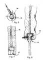
- Fig. 1shows in a longitudinal section a blood vessel 1 with a first sheath 2 in tube form, which protrudes with its distal end into the blood vessel 1 in the direction of a heart chamber 3 to the aortic arch.
- the lock 2is inserted through an opening 4 in the blood vessel 1 and ideally sealed there.
- the first lock 2has a flange 6.
- a cardiac catheter 8is shown, which is hollow and in which a drive shaft for a likewise shown in dashed lines heart pump 9 runs.
- the pump 9is inserted into the heart chamber 3 and has a rotor which rotates at high speed, driven by the shaft, in order to convey blood from the heart chamber into the blood vessel 1.
- a strand-shaped body 10is shown in front of the flange 6, which is to be inserted in the direction of the arrow 11 in the lock 2.
- the strand-shaped body 10is shown only in sections there.
- the strand-like bodyis formed for example by the heart catheter 8, which together with the flexible drive shaft therein represents a flexible strand-like body and is to be inserted through the sheath 2 into the blood vessel 1 and further into the heart chamber 3.
- the catheter travelis greater than 80 cm in the patient's body.
- the strand-like body 10may also consist of a cardiac catheter 8, which is surrounded by a second, tubular lock. This second lock is then designed to hold the radially compressible pump compressed.
- the second sheathmay conveniently be pre-assembled with the cardiac catheter 8 and the pump prior to use on a patient.
- the second lockcan then be held axially to the first lock and fixed there, for example by means of the pusher according to the invention. While the second sheath is pressed axially against the first sheath, the heart catheter can then be pushed through the second sheath into the first sheath and through it into the blood vessel.
- a pushing deviceWhen the heart catheter is pushed axially into the second sheath, a pushing device according to the invention can likewise be used. This is then attached to the second lock opposite the first lock and encloses the portion of the cardiac catheter before the second lock.
- Fig. 2shows a more detailed, but schematic representation of the pump catheter 8 with the flexible drive shaft 12. This is connected proximally to a drive in the form of a motor 13 and distally to a drive hub 14 within a pump housing 15.
- the hub 14carries rotor blades 16 for conveying a fluid or blood.
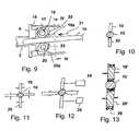
- the Fig. 3shows in three-dimensional view a construction of a pusher.
- Fig. 4shows the same view as a line drawing and Fig. 5 a longitudinal section.
- a guide device 56 in the form of a two-part hollow cylinder with a lower half 57 and an upper half 58is shown.
- the cylindrical cavity 59receives the strand-like body 60 to be pushed, as well as a second lock, and supports it radially.
- the upper half 58is connected by screws 61, 62 to the lower half 57, which slide in oblong holes. The long holes are extended at one end, so that after moving the upper half this can be removed.
- a holding unit / Axialkrafteinmay have recesses for tear tabs 65 of a second lock, when the second lock is designed as a so-called "peel-off" Schleuse.
- the second lockby virtue of its material structure (molecular orientation, anisotropic structure) and / or the introduction of predetermined breaking points (perforation), is designed to be torn lengthwise and removed after pushing through a cardiac catheter.
- Fig. 8shows for further illustration a cross section Fig. 6 .
- Fig. 9shows concretely another embodiment of a feed device, wherein the flange 6 of the first lock 2 is shown on the left side and the pusher in the right part of the figure.
- the pushing devicehas a tubular housing 17, whose distal end 18 can be pushed onto the flange 6 and fixed there relative to the flange 6.
- the fixationcan for example by means of a central thread on the flange 6 and be realized at the housing end 18 or by a bayonet lock between these parts.
- screw and other adhesive compoundssuch as gluing or magnetic adhesion conceivable. It makes sense if the connection between the thruster and the flange 6 of the lock is easily released again.
- the pushermay also have a cavity for receiving and fixing the flange 6 and an opening for introducing the flange into the cavity.
- At least two friction wheels 19, 20are rotatably mounted as part of a Axialkraftein Arthurs worn or holding unit, each having at its periphery a friction lining 19a, 20a, which has a high coefficient of friction against the material of the strand-like body 10.
- the strand-shaped body 10is typically clamped between the friction wheels 19, 20.
- the strand-shaped bodycan be both a catheter and a second lock.
- the friction wheels 19, 20may for example be controllable in their rotatability. If they are blocked, by axial movement of the pusher together with the friction wheels, if they are guided in the housing 17, the strand-shaped body in the direction of the arrow 21 can be advanced. If the pusher is retracted against the direction of the arrow 21, the friction wheels 19, 20 can be released, for example by a controller or a freewheel, so that in this movement of the pusher, the strand-shaped body 10 is not taken, but in the position relative to the lock 2 remains. Before re-advancing the pusher in the direction of the arrow 21, the friction wheels 19, 20 are blocked again. For example, in order to realize such a drive mechanism, the housing 17 can be displaced axially back and forth on a neck of the flange 6.
- Another variant of a drivecan provide that the friction wheels 19, 20 can be driven in the direction of the arrows 22, 23 when the thrust device is stationary, in order to push the strand-shaped body 10 in the direction of the arrow 21.
- This varianthas the advantage that the speed of the friction wheels 19, 20 or the torque, for example based on the current of an electric motor driving the friction wheels, can be detected.
- the corresponding sensed quantitiesmay be used to control the rate of advance of the rope shaped body or to control the thrust force to limit it and thereby avoid injury to the insertion of a catheter into a lumen within a patient's body.
- the thrustfor example, be limited by a slip clutch.
- Fig. 10shows in a plan view along the line IV-IV according to Fig. 3 the two friction wheels 19, 20 and the pin-shaped body 10 clamped between them.
- Fig. 11is shown that certainly more than two, for example four friction wheels 19, 20 can be provided distributed on the circumference of the strand-shaped body 10. For example, these may be three, five or six friction wheels.
- a rotatable bearingis schematically illustrated by a stylized wave.
- the friction wheelscan be driven for example by means of individual motor drives or together via a coupling gear. It can also be provided that only a few of the friction wheels or a single one of them can be driven. The remaining friction wheels would rotate automatically in this case when driving a single friction wheel.
- Fig. 12shows an example of an implementation of a drive via two electric motors 24, 25.
- the friction wheelsare schematically shown as cylindrical wheels, possibly with a friction lining.
- a concave outer peripheral surface of the friction wheels 19 ', 20'may be provided.
- the concave surfaces 26are designed such that they conform to the strand-like body 10 and also hold it laterally so that a reliable radial guidance of the rope-shaped body can already be ensured with two friction wheels.
- Fig. 14shows a feed device with an axial force introduction unit 27 in the form of a push cylinder 28 which is on a guide body 29 in the directions of the arrow 30 back and forth.
- the push cylinder 28has at one end a bead-shaped disc 31 with a central opening which is surrounded by a circumferential movable lip 32. The opening is dimensioned such that the edge of the lip 32 rests on the strand-like body 10. If the thrust cylinder 28 on the Sluice 2 to pushed, the lip 32 is deflected in the direction of the arrow 33, and the central opening of the bead disc 31 is reduced and clamps the strand-like body 10 a. This is then taken in the direction of the lock 2 out and moved there.
- the strand-like body 10can be jerkily moved into the lock 2.
- the movement of the push cylinder 28is guided on the guide body 29, so that the movement path of the axial force introduction unit is fixed.
- the strand-shaped bodyis also guided in a cylindrical opening 35 of the guide body 29 and further in the direction of the lock 2 by two or more mutually opposite freely rotatable movable friction wheels 19, 20. It can also be a guide by several axially successive groups of friction wheels on the one hand or be provided exclusively by a long hollow cylindrical opening to the flange 6 of the lock 2 out.
- the flange 6 of the lock 2is a similarly constructed flange 36 of the guide body 29 opposite, so that the two flanges 6, 36 by a screw connection, represented by an exemplary dashed line 37, can be connected together.
- a plurality of screws on the circumference of the flangesin particular symmetrically distributed.
- a cross section along the section line IX-IX in the Fig. 14is in the Fig. 15 shown, with the central opening 35 in the guide body 29, which is surrounded by the cylinder 28 of the axial force introduction unit 27.
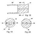
- Fig. 16shows another variant of an axial force introduction device, for example, in the pusher according to Fig. 14 instead of the Axialkraftein Arthurs Surprise 27 can be used.
- a push cylinder 28 'is shown, which may be axially guided on the guide body 29.
- a foam body 38which can be compressed radially by pressure in the direction of the arrows 39, 40 to compress the opening 35 'and the strand-like body in the opening 35' clamped.
- the foam cylinder 38can be compressed by hand while simultaneously performing a pushing movement in the direction of the lock 2 out.
- the strand-like bodycan be inserted into the lock 2 a bit far.
- the radial pressure on the foam cylinder 38is reduced, so that the opening 35 'increases elastically in the radial direction and the strand-shaped body is released.
- the axial force introduction unitcan then be retracted proximally to the rope-shaped body.
- Fig. 17shows a cross section through the foam cylinder 38 with the opening 35 '.
- a further variant of an axial force introduction unitis shown, with a massive push cylinder 41 having a guide tube 28 '' on the guide cylinder 29 as in Fig. 14 can be performed represented.
- the cylinder 41may be completely severed and consist of two halves 44, 45 connected only by springs 42, 43. These have in the relaxed state of the springs 42, 43 at a distance which is dimensioned so that in the central recess 35 '' of the strand-shaped body 10 is accommodated with play. If the halves 44, 45 are compressed against the force of the springs 42, 43, the strand-like body can be clamped in the opening 35 ". In the clamped state, the strand-shaped body can then be advanced. For example, the two halves 44, 45 of the cylinder 41 may be manually compressed when manipulating the pusher and released upon retraction of the cylinder 41.
- Fig. 20shows a similar embodiment, wherein the cylinder 41 is not completely separated in two halves, but a film hinge 46 has remained on one side of the cylinder 41, which allows to unfold the two halves 44 ', 45'.
- the film hinge 26may also be provided a separate hinge. The mode of operation when clamping the strand-like body corresponds to the basis of the Fig. 19 shown.
- Fig. 21shows a pusher, which is different from the devices shown in the preceding figures. It is there at a lock 2, and more precisely at the flange 6, a flange 46 of a guide body 47 attached.
- the guide body 47has a guide rail for the strand-like body 10, which may for example be given by a semi-cylindrical or partially cylindrical recess in which the strand-shaped body 10 may be located.
- Fig. 22shows in cross section the guide body 47 with the part-cylindrical recess 48, in which the strand-shaped body 10 is located.
- a drive body 49which forms the axial force introduction unit.
- This drive body 49for example, also has a part-cylindrical recess which at least partially accommodates the strand-shaped body 10.
- the drive body 49can be displaced in the axial direction, represented by the double arrow 50, proximally or distally.
- a particular feature of the guide body 47 and the drive body 49can be realized, for example, that the friction between the drive body 49 and the strand-shaped body 10 by the choice of material with a higher coefficient of static friction is substantially greater than the friction between the strand-shaped body 10 and the guide body 47th
- the guide body 47made of a particularly smooth material with a low coefficient of friction, such as PTFE, exist or be coated with such a material.
- the drive body 49in turn may be made of a material which has a higher coefficient of friction with respect to the strand-shaped body 10, for example an elastomer, especially rubber or silicone rubber.
- an elastomerespecially rubber or silicone rubber.
- the strand-like body 10upon insertion of the strand-like body 10 into the sheath 2, it is simultaneously pressed radially onto the drive body and moves it distally in the direction of the sheath 2.
- the pressure forceis reduced to the strand-like body, so that it is not taken and remains in the lock 2. In this way, the strand-like body can gradually be conveyed into the lock 2.
- Fig. 23may be provided on the guide body 47 and a pistol-like handle, which has a lever 51 which is movable against a spring 52.
- the lever 51is pivotally mounted and has a plunger 53 which presses against a clamping plate 54, this jammed against the drive body 49 and causes a thrust movement of the drive body 49.
- the clamping discis spring-loaded against the direction of the arrow 55.
- the in the Figures 9-23 shown devicecan be used on the one hand for a second lock, to push them as a strand-shaped body against a first lock and to allow the pushing through of a pump head with minimized risk of kinking of the pump catheter.
- this devicecan also be proximal to one in the Figures 3-8 shown holding a second lock to be connected to allow the kink-free insertion of a catheter (possibly with pump head) in a second lock. In this way, therefore, two pushers can be combined.
Landscapes
- Health & Medical Sciences (AREA)
- Engineering & Computer Science (AREA)
- Heart & Thoracic Surgery (AREA)
- Life Sciences & Earth Sciences (AREA)
- Veterinary Medicine (AREA)
- Public Health (AREA)
- Biomedical Technology (AREA)
- Hematology (AREA)
- Anesthesiology (AREA)
- Animal Behavior & Ethology (AREA)
- General Health & Medical Sciences (AREA)
- Mechanical Engineering (AREA)
- Cardiology (AREA)
- Biophysics (AREA)
- Pulmonology (AREA)
- Vascular Medicine (AREA)
- Media Introduction/Drainage Providing Device (AREA)
- Surgical Instruments (AREA)
Abstract
Translated fromGermanDescription
Translated fromGermanDie Erfindung liegt auf dem Gebiet der Mechanik, insbesondere des Maschinenbaus bzw. der Feinwerktechnik. Sie befasst sich mit den mechanischen Problemen, die bei einem Einschieben eines flexiblen strangförmigen Körpers in eine Öffnung bzw. eine Schleuse aufgrund seiner Tendenz zum Ausknicken entstehen.The invention is in the field of mechanics, in particular mechanical engineering or precision engineering. It deals with the mechanical problems that arise when inserting a flexible strand-like body in an opening or a lock due to its tendency to buckling.
Derartige flexible strangförmige Körper können beispielsweise Seile, Drähte, Fäden, Schläuche oder eine Kombination solcher Elemente sein, die typischerweise in Schleusen oder Öffnungen, Rohre, Schläuche oder allgemein Hohlräume eingeschoben werden sollen. Ein solcher strangförmiger Körper kann auch eine zweite Schleuse sein, die in eine erste Schleuse eingeschoben oder dieser gegenüber ortsfest gehalten werden soll. Wenn sich beim Schieben solcher Körper ein Widerstand gegen eine weitere Schubbewegung ergibt, so muss der Körper, um eine weitere Schubbewegung zu ermöglichen, am Ausknicken gehindert werden, oder entsprechende radiale Ausweichbewegungen müssen begrenzt werden.Such flexible strand-like bodies may be, for example, cables, wires, threads, tubes or a combination of such elements, which are typically to be inserted in locks or openings, pipes, hoses or generally cavities. Such a strand-shaped body may also be a second lock, which is to be inserted into a first lock or this is to be held stationary. If, when pushing such bodies, there is resistance to further pushing movement, so the body must be prevented from kinking in order to allow a further pushing movement, or corresponding radial evasive movements must be limited.
Insgesamt geht es unter anderem darum, dass die Handhabung so sicher wie möglich gestaltet wird. Vorteilhaft ist es dabei, wenn beim Einführen ein bestimmter Knickwinkel nicht überschritten und ein bestimmter Biegeradius nicht unterschritten wird.Overall, it is one of the things that makes handling as safe as possible. It is advantageous if during insertion a certain bending angle is not exceeded and a certain bending radius is not exceeded.
Typischerweise ergeben sich derartige Probleme unter anderem in der Medizintechnik, wenn beispielsweise eine Kanüle oder ein Katheter in eine Körperöffnung, ein körpereigenes Lumen oder ein artifizielles Lumen eingeschoben werden soll.Typically, such problems arise, inter alia, in medical technology, for example, when a cannula or a catheter is to be inserted into a body opening, an endogenous lumen or an artificial lumen.
Typische derartige Situationen sind beispielsweise aus der internationalen Patentanmeldung
Da derartige Pumpen über Längen von einigen zehn Zentimetern durch ein Blutgefäß innerhalb eines Körpers geschoben werden sollen, ist mit einem gewissen Schubwiderstand zu rechnen, der eine entsprechende Schubkraft beim Einschieben notwendig macht. Insbesondere bei selbstentfaltbaren bzw. selbstexpandierbaren Pumpenköpfen ist aufgrund der auftretenden Rückstellkräfte des gefalteten bzw. komprimierten Pumpenkopfes mit einem erhöhten Schubwiderstand zu rechnen. Besonders deshalb, weil bei derartigen Pumpen innerhalb eines zu schiebenden Katheters eine für hohe Drehzahlen und eine lange Standzeit vorgesehene biegsame Welle verläuft, die knickempfindlich ist, muss sichergestellt werden, dass die notwendige Schubkraft auf den Katheter angewendet werden kann, ohne dass dieser ausknickt oder anderweitig ausweicht.Since such pumps are to be pushed over lengths of a few tens of centimeters through a blood vessel within a body, is to be expected with a certain shear resistance, which makes a corresponding thrust force when inserting necessary. In particular, in selbstentfaltbaren or self-expandable pump heads is due to the restoring forces of the folded or compressed pump head to be expected with an increased shear resistance. Especially because at For such pumps within a catheter to be slidably provided a high speed and long life flexible shaft which is kink sensitive, it must be ensured that the necessary thrust can be applied to the catheter without buckling or otherwise evading it.
Der vorliegenden Erfindung liegt die Aufgabe zugrunde, eine Schubvorrichtung zum axialen Einschieben eines strangförmigen, flexiblen Körpers in eine Schleuse oder zur sicheren Halterung eines solchen Körpers gegenüber einer Schleuse zu schaffen, die möglichst einfach aufgebaut ist, die einfache Erzeugung einer Schubbewegung ermöglicht und ein Ausweichen des strangförmigen Körpers zuverlässig verhindert.The present invention has for its object to provide a thrust device for axially inserting a strand-like, flexible body in a lock or for secure support of such a body against a lock, which is as simple as possible, allows easy generation of a pushing movement and avoiding the strand-shaped body reliably prevented.
Die Aufgabe wird gemäß der Erfindung mit den Merkmalen des Patentanspruchs 1 gelöst.The object is achieved according to the invention with the features of
Dazu ist eine Halteeinheit vorgesehen, die als Axialkrafteinleitungseinheit ausgebildet sein kann, die durch Kraft- oder Formschluss eine axiale Halte- oder Schubkraft auf den strangförmigen Körper aufbringt und die relativ zu der Schleuse ortsfest angeordnet oder auf einer vorgegebenen Bewegungsbahn geführt ist. Unter der axialen Richtung soll in diesem Zusammenhang die Längsachsenrichtung der Schleuse und/oder des strangförmigen Körpers verstanden werden.For this purpose, a holding unit is provided, which may be formed as Axialkrafteinleitungseinheit, which applies by force or positive locking an axial holding or thrust force on the strand-like body and which is arranged stationary relative to the lock or guided on a predetermined trajectory. In this context, the axial direction should be understood to mean the longitudinal axis direction of the lock and / or the strand-like body.
Da oft nicht unmittelbar an einem Ende des strangförmigen Körpers angegriffen werden kann, muss eine Axialkrafteinleitungseinheit entweder durch Klemmen, d. h. Kraftschluss und entsprechende Haftreibungskräfte, oder durch einen Formschluss an dem strangförmigen Körper angreifen, sofern dieser entsprechende Formelemente an der Außenseite aufweist. Ein entsprechendes Verklemmen oder ein Formschluss erlaubt dann das Aufbringen einer Axialkraft und damit eine Haltekraft oder eine Schubbewegung. Beispielsweise kann vorgesehen sein, dass sowohl die (erste) Schleuse als auch der strangförmige Körper, der ja auch als (dann zweite) Schleuse ausgebildet sein kann, jeweils einen Flansch aufweisen, wobei jeder der Flansche in je eine Ausnehmung der Schubvorrichtung oder beide Flansche gemeinsam in eine einzige Ausnehmung der Schubvorrichtung derart einlegbar sind, dass die Flansche in Axialrichtung und/oder Radialrichtung festgelegt sind.Since often can not be attacked directly at one end of the strand-like body, an axial force introduction unit must either by clamping, ie adhesion and corresponding static friction forces, or by a positive connection to the strand-like Attack body, provided that it has corresponding form elements on the outside. A corresponding jamming or positive locking then allows the application of an axial force and thus a holding force or a pushing movement. For example, it may be provided that both the (first) lock and the strand-shaped body, which may also be formed as (then second) lock, each having a flange, each of the flanges in each recess of the thruster or both flanges together can be inserted in a single recess of the pusher such that the flanges are fixed in the axial direction and / or radial direction.
Die Schubvorrichtung kann zum Einlegen des Flansches / der Flansche in die Ausnehmung(en) demontierbar sein und beispielsweise als längsgeteilter Hohlkörper, insbesondere Hohlzylinder ausgebildet sein.The thrust device can be removable for inserting the flange / flanges into the recess (s) and be designed, for example, as a longitudinally divided hollow body, in particular a hollow cylinder.
Dadurch, dass in der Schubvorrichtung die Halteeinheit/Axialkrafteinleitungseinheit ortsfest zur (ersten) Schleuse angeordnet ist, kann der Abstand und die Ausrichtung der Einheit derart gewählt werden, dass die Axialbelastung des strangförmigen Körpers gut kontrollierbar und begrenzbar ist, dass nur unschädliche Radialkräfte und Radialauslenkungen auf den strangförmigen Körper aufgebracht werden und dass die freie Länge des strangförmigen Körpers zwischen der Axialkrafteinleitungseinheit und der Schleuse definiert bzw. begrenzt werden kann.Characterized in that the holding unit / Axialkrafteinleitungseinheit is fixed to the (first) lock in the pusher, the distance and the orientation of the unit can be chosen such that the axial load of the strand-like body is well controlled and limited, that only harmless radial forces and radial deflections the strand-shaped body are applied and that the free length of the strand-like body between the axial force introduction unit and the lock can be defined or limited.
Auch wenn die Axialkrafteinleitungseinheit auf einer vorgegebenen Bewegungsbahn geführt ist, kann diese entsprechend so gewählt werden, dass die Tendenz des strangförmigen Körpers, bei einer Schubbewegung seitlich auszubrechen, minimiert ist. Zudem kann eine mechanische Führung für den strangförmigen Körper bei einer vorgegebenen Bewegungsbahn der Axialkrafteinleitungseinheit gut dimensioniert und positioniert werden.Even if the Axialkrafteinleitungseinheit is guided on a predetermined trajectory, this can be chosen accordingly so that the tendency of strand-shaped body to break laterally during a pushing movement is minimized. In addition, a mechanical guide for the strand-shaped body can be well dimensioned and positioned at a predetermined trajectory of the axial force introduction unit.
Die Führung der Axialkrafteinleitungseinheit kann beispielsweise mittels einer ein- oder mehrstufigen teleskopartigen Führung, beispielsweise mit konzentrischen Rohren, oder durch Führung in einer Schiene oder einem zylindrischen Hohlraum realisiert sein.The guidance of the axial force introduction unit can be realized for example by means of a single or multi-stage telescopic guide, for example with concentric tubes, or by guiding in a rail or a cylindrical cavity.
Vorteilhaft kann vorgesehen sein, dass die Schubvorrichtung unmittelbar mechanisch an die Schleuse gekoppelt ist. Dies kann beispielsweise durch ein Zentralgewinde, einen Bajonettverschluss, durch die Anwendung von Adhäsionskräften, mittels einer magnetischen Kopplung, mittels exzentrischer Verschraubung (beispielsweise durch am Umfang verteilte Schrauben), durch Kleben, durch elektrostatische Anziehungskräfte, durch elastische Halteelemente wie beispielsweise Federn, Klammern oder Gummizüge oder durch Einlegen eines Passstückes der Schleuse in eine passend geformte Ausnehmung der Halteeinheit erreicht werden.Advantageously, it can be provided that the pusher is mechanically coupled directly to the lock. This can for example by a central thread, a bayonet fitting, by the application of adhesive forces, by means of a magnetic coupling, by eccentric screwing (for example by circumferentially distributed screws), by gluing, by electrostatic attraction, by elastic holding elements such as springs, clamps or elastics or by inserting a fitting piece of the lock in a suitably shaped recess of the holding unit can be achieved.
Vermieden werden soll insbesondere ein Ausweichen des strangförmigen Körpers beim Eintritt in die Schleuse, da in der Schleuse und in dem zur Schleuse gehörigen Schlauch eine mechanische Führung und radiale Stützung üblicherweise gegeben ist oder einfach hergestellt werden kann und hinter der Schleuse bzw. dem zur Schleuse gehörigen Schlauch aufgrund der verminderten Rückstellkräfte das Knickrisiko eine untergeordnete Rolle spielt.In particular, avoidance of the strand-like body when entering the lock should be avoided, as in the lock and in the hose belonging to the lock mechanical guidance and radial support is usually given or can be easily made and behind the lock or belonging to the lock Hose due to the reduced restoring forces the risk of breakage plays a minor role.
Durch die Kopplung der Schubvorrichtung an die Schleuse wird der Abstand zwischen der Halteeinheit/Axialkrafteinleitungseinheit und der Schleuse begrenzt, und es wird eine definierte Führung des strangförmigen Körpers und/oder eine radiale Stützung ermöglicht. Es ist auch besonders einfach, die Bewegungsbahn der Axialkrafteinleitungseinheit, falls eine solche vorgesehen ist, in Bezug auf die Schleuse festzulegen.By coupling the pusher to the lock, the distance between the holding unit / Axialkrafteinleitungseinheit and the lock is limited, and it is a defined leadership of the strand-shaped body and / or a radial support allows. It is also particularly easy to determine the trajectory of the axial force introduction unit, if one is provided, in relation to the lock.
Zur Kopplung kann die Schleuse beispielsweise einen Flansch oder eine ebene Frontplatte mit einer Öffnung aufweisen, in die der strangförmige Körper eingeführt werden soll, wobei an die Frontplatte bzw. den Flansch ein entsprechender Gegenflansch der Schubvorrichtung angekoppelt werden kann. Dabei können übliche lösbare Verbindungstechniken angewendet werden oder auch die üblichen Fügetechniken wie Kleben oder andere adhäsive Wirkungen, die vorteilhaft jedoch eine lösbare Verbindung herstellen sollen.For coupling, the lock may, for example, have a flange or a flat front plate with an opening into which the strand-like body is to be inserted, wherein a corresponding counter flange of the pusher can be coupled to the front plate or the flange. In this case, conventional releasable bonding techniques can be used or the usual joining techniques such as gluing or other adhesive effects, which are advantageous to produce a detachable connection.
Sollen durch die Schubvorrichtung lediglich die erste Schleuse und ein strangförmiger Körper, beispielsweise eine zweite Schleuse, axial gegeneinander gedrückt werden, so können auch ein Flansch oder eine Frontplatte der ersten Schleuse einerseits und ein Flansch der zweiten Schleuse oder eines anderen strangförmigen Körpers gegeneinander fixiert sein.If only the first lock and a strand-shaped body, for example a second lock, are axially pressed against one another by the pushing device, a flange or a front plate of the first lock on the one hand and a flange of the second lock or another strand-shaped body can also be fixed against one another.
Es kann aber auch beispielsweise eine Verbindung durch Ineinanderstecken geschaffen werden, die durch Kraft- bzw. Formschluß gehalten wird. Wichtig ist hierbei im Wesentlichen, dass die Kräfte zum Halten der Verbindung größer sind als die Kräfte, die zum Schieben des strangförmigen Körpers erforderlich sind, damit die Verbindung nicht beim Schieben des strangförmigen Körpers ungewollt gelöst wird.But it can also be created, for example, a connection by nesting, which is held by force or positive engagement. What is important here is essentially that the forces for holding the connection are greater than the forces required for pushing the rope-shaped body are, so that the connection is not unintentionally solved when pushing the strand-shaped body.
Eine mechanische Kopplung kann vorteilhaft auch unmittelbar zwischen der Axialkrafteinleitungseinheit und der Schleuse vorgesehen sein. Dadurch kann eine Radialführung zwischen der Axialkrafteinleitungseinheit und der Schleuse minimiert oder ganz weggelassen werden. Die Baugröße der Schubvorrichtung kann damit auch gering gehalten werden.A mechanical coupling can advantageously also be provided directly between the axial force introduction unit and the lock. As a result, a radial guide between the axial force introduction unit and the lock can be minimized or omitted altogether. The size of the pusher can thus be kept low.
Vorteilhaft kann die Schubvorrichtung eine an der Schleuse mittels der Kopplung befestigbare Führungseinrichtung aufweisen, die den strangförmigen Körper radial stützt, wobei die Axialkrafteinleitungseinheit relativ zu der Führungseinrichtung entweder ortsfest angeordnet oder auf einer vorgegebenen Bewegungsbahn geführt ist. In diesem Fall ist zwischen der Axialkrafteinleitungseinheit und der Schleuse die Führungseinrichtung vorgesehen, die entweder dazu dient, einen Abstand zwischen der Axialkrafteinleitungseinrichtung und der Schleuse zu überbrücken und damit die Aufbringung einer Schubkraft handhabbar zu machen und/oder bei einem an sich geringen Abstand zwischen der Axialkrafteinleitungseinheit und der Schleuse diesen durch die Führungseinrichtung derart zu gestalten, dass der strangförmige Körper auf dieser Distanz keinesfalls radial ausweichen kann.Advantageously, the pusher device can have a guide device which can be fastened to the lock by means of the coupling and supports the strand-shaped body radially, wherein the axial force introduction unit is either fixedly arranged relative to the guide device or guided on a predetermined movement path. In this case, the guide device is provided between the Axialkrafteinleitungseinheit and the lock, which serves either to bridge a distance between the Axialkrafteinleitungseinrichtung and the lock and thus make the application of a thrust manageable and / or at a small distance between the axial force introduction unit and the lock to make them by the guide means such that the strand-like body can avoid radially avoiding at this distance.
Die Axialkrafteinleitungseinheit kann vorteilhaft eine Radialklemmeinrichtung aufweisen, die durch Anpressen eines Klemmwerkzeuges an den strangförmigen Körper in Radialrichtung eine Haftung erzeugt, die zum Aufbringen einer Schub- oder Haltekraft in Axialrichtung dient. Das Klemmwerkzeug kann beispielsweise beweglich ausgestaltet sein und an dem strangförmigen Körper abrollen.The Axialkrafteinleitungseinheit can advantageously have a radial clamping device which generates by pressing a clamping tool to the strand-like body in the radial direction of adhesion, which serves for applying a pushing or holding force in the axial direction. The clamping tool, for example be designed movable and roll on the strand-like body.
Speziell kann/können als Klemmwerkzeug wenigstens ein, insbesondere zwei, drei oder vier Reibräder vorgesehen sein, die einander wenigstens teilweise in Bezug auf den strangförmigen Körper radial gegenüberliegen. Der strangförmige Körper kann dann zwischen den Reibrädern eingeklemmt sein und durch diese radial gestützt werden. Durch einen Antrieb der Reibräder kann eine Schubbewegung auf den strangförmigen Körper aufgebracht werden. Es können auch mehrere Sätze von Reib- oder Rändelrädern in Längsrichtung des strangförmigen Körpers hintereinander angeordnet werden.Specifically, at least one, in particular two, three or four friction wheels can be provided as a clamping tool, which are radially opposite each other at least partially with respect to the strand-shaped body. The strand-like body can then be clamped between the friction wheels and supported radially by them. By driving the friction wheels, a pushing movement can be applied to the strand-like body. It is also possible to arrange a plurality of sets of friction or knurling wheels in the longitudinal direction of the strand-shaped body one behind the other.
Es kann auch vorgesehen sein, dass die Reibräder, oder wenigstens eines von ihnen, eine Freilaufeinrichtung aufweisen, die eine Rotation in jeweils nur einer Richtung erlaubt, so dass beispielsweise bei Vorschieben der Schubvorrichtung die Reibräder sperren und den strangförmigen Körper schieben und bei Zurückziehen der Schubvorrichtung die Reibräder derart rotieren, dass die Schubvorrichtung gegenüber dem strangförmigen Körper kraftfrei verschoben werden kann. Damit kann schrittweise der strangförmige Körper beispielsweise von Hand oder mittels eines anderen Antriebs durch Verschieben der Schubvorrichtung geschoben werden.It can also be provided that the friction wheels, or at least one of them, have a freewheel device that allows rotation in only one direction, so that, for example, when advancing the thruster lock the friction wheels and push the rope-shaped body and retracting the pusher rotate the friction wheels in such a way that the pusher can be displaced without force relative to the strand-like body. Thus, the strand-like body can be gradually pushed, for example by hand or by another drive by moving the pusher step by step.
Derartige Antriebe können beispielsweise durch Elektromotoren an den Reibrädern vorgesehen sein, so dass die Schubvorrichtung ortsfest stillstehen kann. Damit ergibt sich auch ein verringerter Platzbedarf bei Anwendung der Schubvorrichtung.Such drives can be provided for example by electric motors on the friction wheels, so that the pusher can be stationary stationary. This also results in a reduced space requirement when using the pusher.
Allgemein kann es sinnvoll sein, dass die Reibräder bezüglich ihrer Rotation steuerbar sind, d. h. entweder aktiv antreibbar oder beispielsweise von außen gesteuert sperrbar. Der kontinuierliche Antrieb der Schubvorrichtung mittels eines Rotationsantriebs der Reibräder lässt beispielsweise auch die Steuerung der eingeleiteten Schubkraft in Abhängigkeit vom Vorschub, der Vorschubgeschwindigkeit oder einer erfassten Gegenkraft zu. Damit kann verhindert werden, dass beispielsweise ein Katheter, der in einen Körper eingeschoben wird, in dem Fall, dass ein erhöhter Widerstand durch Anstoßen an Gefäßwände entsteht, einfach weitergeschoben wird. Eine entsprechende Steuerung kann den Schubvorgang stoppen oder verlangsamen. Eine entsprechende Steuerung, die elektronisch ausgestaltet sein kann, kann entweder die Schubkraft oder die Schubgeschwindigkeit entweder nach einer vorgegebenen Kurve/Charakteristik oder in Abhängigkeit vom Schubwiderstand steuern.In general, it may be useful that the friction wheels are controllable with respect to their rotation, d. H. either actively drivable or, for example, controlled from the outside lockable. The continuous drive of the thruster by means of a rotary drive of the friction wheels also allows, for example, the control of the initiated thrust in dependence on the feed, the feed rate or a detected counterforce. This can be prevented, for example, that a catheter which is inserted into a body, in the event that an increased resistance arises by abutment against vessel walls, is simply pushed on. An appropriate control can stop or slow down the pushing process. A corresponding controller, which may be configured electronically, can control either the thrust or the thrust speed either according to a given curve / characteristic or as a function of the thrust resistance.
Es kann auch vorteilhaft vorgesehen sein, dass das Klemmwerkzeug mit Klemmbacken radial beiderseits des strangförmigen Körpers versehen ist und dass die Klemmbacken mit dem zwischen ihnen festgelegten strangförmigen Körper im Wesentlichen in dessen Axialrichtung gegenüber der Schleuse und/oder einer Führungseinrichtung geführt bewegbar sind.It can also be advantageously provided that the clamping tool is provided with clamping jaws radially on both sides of the strand-like body and that the jaws are guided with the strand-shaped body defined between them substantially in the axial direction against the lock and / or a guide device.
Die Klemmbacken können dabei als zwei oder mehr in Radialrichtung bezüglich des strangförmigen Körpers relativ zueinander bewegbare Körper ausgebildet sein, die beispielsweise auch nachgiebig, insbesondere weicher als der strangförmige Körper selbst, ausgebildet sein können. Zu diesem Zweck sollten die Klemmbacken aus einem weichen Material wie beispielsweise Kunststoff oder einem Elastomer bestehen oder mit einem solchen Werkstoff beschichtet sein. Es kann auch vorgesehen sein, dass nur einige Klemmbacken beweglich ausgebildet sind, während andere Klemmbacken ortsfest fixiert sind.The jaws may be formed as two or more in the radial direction with respect to the strand-shaped body relative to each other movable body, which may for example also be compliant, especially softer than the strand-shaped body itself, may be formed. For this purpose, the jaws should be made of a soft material such as plastic or an elastomer or be coated with such a material. It can also be provided that only a few jaws are designed to be movable while other jaws are fixed in place.
Es können beispielsweise zwei, drei, vier, fünf oder mehr Klemmbacken vorgesehen sein, die einander am Umfang des strangförmigen Körpers gegenüberliegen.For example, two, three, four, five or more jaws may be provided which oppose each other at the periphery of the rope-shaped body.
Besonders vorteilhaft können die Klemmbacken durch zwei oder mehr Teile beispielsweise eines Hohlzylinders bzw. einer beliebigen anderen zum strangförmigen Körper korrespondierenden Form gebildet sein, der den strangförmigen Körper aufnimmt. Die Klemmbacken können dann Sektorkörper des Hohlzylinders bilden. Unter einem Hohlzylinder soll in diesem Zusammenhang ein Körper verstanden werden, der eine, insbesondere zylindrische, durchgehende Öffnung aufweist. Ein solcher Körper kann beispielsweise auch auf seiner Außenseite eine zylindrische Form aufweisen. Anstelle eines Hohlzylinders kann auch ein andersartiger Körper mit einer durchgehenden Öffnung verwendet werden.Particularly advantageously, the jaws can be formed by two or more parts, for example, a hollow cylinder or any other shape corresponding to the strand-like body, which receives the strand-like body. The jaws can then form sector body of the hollow cylinder. Under a hollow cylinder should be understood in this context, a body having a, in particular cylindrical, through-opening. Such a body may for example also have on its outer side a cylindrical shape. Instead of a hollow cylinder and a different body with a through hole can be used.
Die entsprechenden Sektorkörper können dann beispielsweise dieselbe Länge aufweisen wie der Hohlzylinder und am Umfang des strangförmigen Körpers verteilt sein. Die Schubvorrichtung kann auch derart ausgebildet sein, dass erste Klemmbacken in axialer Richtung unbeweglich angeordnet sind und aus einem Material bestehen, das eine geringe Reibung gegenüber dem Material des strangförmigen Körpers aufweist. Zweite Klemmbacken sind dagegen axial beweglich und weisen einen höheren Reibungskoeffizienten gegenüber dem Material des strangförmigen Körpers auf, so dass der strangförmige Körper durch die zweiten Klemmbacken gegen die ersten Klemmbacken gedrückt werden und auf diesen wie auf einer Führungsschiene in axialer Richtung gleitend bewegt werden kann. Auf diese Weise kann durch die Klemmbacken sowohl die radiale Führung für den strangförmigen Körper als auch durch einzelne der Klemmbacken der Vorschub in axialer Richtung realisiert werden.The corresponding sector bodies can then, for example, have the same length as the hollow cylinder and be distributed on the circumference of the strand-like body. The pusher may also be configured such that first jaws are arranged immovably in the axial direction and consist of a material which has a low friction with respect to the material of the strand-shaped body. Second jaws, however, are axially movable and have a higher coefficient of friction compared to the material of the strand-like body, so that the strand-like body through the second jaws can be pressed against the first jaws and slidably moved on these as a guide rail in the axial direction. In this way, both the radial guidance for the strand-like body as well as by individual jaws of the feed can be realized in the axial direction by the jaws.
Ein Verfahren zur Realisierung der Erfindung sieht vor, dass durch eine Steuereinrichtung die Geschwindigkeit des Vorschubs des strangförmigen Körpers gesteuert wird. Dabei kann die Geschwindigkeit als konstante Geschwindigkeit oder auch entsprechend einer vorgegebenen Geschwindigkeits-/Zeit-Charakteristik oder einer Geschwindigkeits-/Weg-Charakteristik angesteuert werden.A method for implementing the invention provides that the speed of the advance of the strand-shaped body is controlled by a control device. The speed can be controlled as a constant speed or according to a predetermined speed / time characteristic or a speed / travel characteristic.
Ergeben sich bei der Schubbewegung unvorhergesehene Widerstände für den strangförmigen Körper, beispielsweise wenn dieser in ein Blutgefäß eines Patienten eingeschoben wird, so kann durch die Steuerung die entsprechende Antriebskraft verstärkt werden, um die Vorschubgeschwindigkeit gemäß der vorgesehenen Charakteristik sicherzustellen.If, during the pushing movement, unforeseen resistances for the strand-shaped body arise, for example when it is pushed into a blood vessel of a patient, then the control can increase the corresponding driving force in order to ensure the feed rate in accordance with the intended characteristic.
Es kann jedoch auch eine Steuerung vorgesehen werden, die den Vorschubwiderstand oder die Vorschubkraft konstant hält, so dass bei Auftreten erhöhter Schubwiderstände auf den strangförmigen Körper die Antriebskraft auf die Schubvorrichtung gesenkt wird, beispielsweise um ein Ausknicken des strangförmigen Körpers durch die Erhöhung von Schubkräften zu verhindern oder um beim medizinischen Einsatz, beispielsweise wenn der strangförmige Körper ein Katheter ist, der in eine Körperöffnung eingeschoben wird, eine Verletzung des Patienten zu vermeiden. Es kann in diesem Fall durch die Steuerung auch der Vorschub vollständig angehalten und der strangförmige Körper ein Stück weit zurückgezogen werden.However, it may also be provided a control that keeps the feed resistance or the feed force constant, so that when increased thrust resistances to the strand-shaped body, the driving force is lowered to the pusher, for example, to prevent buckling of the strand-shaped body by increasing shear forces or in medical use, for example when the strand-shaped body is a catheter inserted into a body opening, to avoid injury to the patient. It can In this case, the control also stops the feed completely and the strand-shaped body is pulled back a bit.
Insofern kann der Schubwiderstand gemessen und die Schubbewegung in Abhängigkeit vom Schubwiderstand gesteuert bzw. geregelt werden. Hierzu sind ein Antrieb, beispielsweise ein elektrischer oder pneumatischer Antrieb, und ein entsprechender Sensor, beispielsweise ein Stromsensor zur Messung der abgenommenen Stromstärke, ein Spannungssensor oder ein entsprechender Drucksensor bei Verwendung einer Pneumatik, sowie eine Steuereinrichtung vorzusehen.In this respect, the shear resistance can be measured and the thrust movement can be controlled or regulated as a function of the thrust resistance. For this purpose, a drive, for example, an electric or pneumatic drive, and a corresponding sensor, for example, a current sensor for measuring the current drawn, a voltage sensor or a corresponding pressure sensor when using a pneumatic, and a control device to provide.
Im Folgenden wird die Erfindung anhand eines Ausführungsbeispiels in einer Zeichnung gezeigt und nachfolgend beschrieben. Dabei zeigt
- Fig. 1
- die Anwendung einer Herzkatheterpumpe bei einem menschlichen Herzen,
- Fig. 2
- eine Pumpeneinrichtung mit einer Herz-katheterpumpe und einer Antriebswelle, die in einem schlauchförmigen Mantel verläuft,
- Fig. 3
- eine Schubvorrichtung in einer dreidimen-sionalen Ansicht,
- Fig. 4
- die Schubvorrichtung aus
Fig. 3 in einer Liniendarstellung, - Fig. 5
- einen Längsschnitt durch die Vorrichtung aus
Fig. 4 , - Fig. 6
- eine als Handgriff ausgestaltete Führungs-einrichtung in einem Längsschnitt mit dem vorderen Ende einer Schleuse,
- Fig. 7
- eine Führungseinrichtung ohne eingelegte Schleuse,
- Fig. 8
- die Führungseinrichtung aus
Fig. 7 in einer Frontansicht. - Fig. 9
- eine Schubvorrichtung mit wenigstens zwei Reibrädern,
- Fig. 10
- eine Draufsicht auf die Vorrichtung nach
Fig. 9 entlang der inFig. 3 mit IV-IV be-zeichneten Linie, - Fig. 11
- eine ähnliche Ansicht wie
Fig. 10 mit vier um den strangförmigen Körper verteilten Reibrädern, - Fig. 12
- eine ähnliche Ansicht wie
Fig. 11 , zusätz-lich mit elektromechanischen Antrieben der Reibräder, - Fig. 13
- eine Anordnung mit zwei Reibrädern, die im Querschnitt konkave Reibflächen aufweisen,
- Fig. 14
- eine Schubvorrichtung ähnlich der aus
Fig. 9 , bei der die Reibräder nur der radi-alen Stützung dienen und eine andere Art der Axialkrafteinleitung vorgesehen ist, - Fig. 15
- eine Ansicht der Einrichtung aus
Fig. 14 entlang der dort mit IX-IX gekennzeichneten Linie, - Fig. 16
- eine weitere Variante der Axialkraft-einleitungseinheit,
- Fig. 17
- einen Querschnitt der Axialkraftein-leitungseinheit aus
Fig. 16 , - Fig. 18
- eine weitere Ausgestaltung der Axialkraft-einleitungseinheit,
- Fig. 19
- eine Querschnittsansicht entlang der Linie XIII-XIII aus
Fig. 18 , - Fig. 20
- eine andere Variante der Axialkraftein-leitungseinheit aus
Fig. 18 , - Fig. 21
- in einem Längsschnitt eine Schubvorrichtung mit axial feststehenden und axial beweg-lichen Klemmbacken,
- Fig. 22
- einen Querschnitt der Einrichtung aus
Fig. 21 entlang der dort mit XVI-XVI ge-kennzeichneten Linie und - Fig. 23
- ein Detail einer Antriebseinrichtung für eine Schubvorrichtung.
- Fig. 1
- the use of a cardiac catheter pump in a human heart,
- Fig. 2
- a pump device with a cardiac catheter pump and a drive shaft which runs in a tubular jacket,
- Fig. 3
- a pusher in a three-dimensional view,
- Fig. 4
- the pusher off
Fig. 3 in a line representation, - Fig. 5
- a longitudinal section through the device
Fig. 4 . - Fig. 6
- designed as a handle guide device in a longitudinal section with the front end of a lock,
- Fig. 7
- a guide device without inserted lock,
- Fig. 8
- the leadership device
Fig. 7 in a front view. - Fig. 9
- a pushing device with at least two friction wheels,
- Fig. 10
- a plan view of the device according to
Fig. 9 along the inFig. 3 IV-IV line, - Fig. 11
- a similar view as
Fig. 10 with four friction wheels distributed around the strand-like body, - Fig. 12
- a similar view as
Fig. 11 , in addition to electromechanical drives of the friction wheels, - Fig. 13
- an arrangement with two friction wheels, which have concave friction surfaces in cross section,
- Fig. 14
- a pusher similar to the one out
Fig. 9 in which the friction wheels serve only the radial support and a different type of axial force transmission is provided, - Fig. 15
- a view of the institution
Fig. 14 along the line marked IX-IX there, - Fig. 16
- another variant of the axial force introduction unit,
- Fig. 17
- a cross section of the Axialkraftein-line unit
Fig. 16 . - Fig. 18
- a further embodiment of the axial force introduction unit,
- Fig. 19
- a cross-sectional view taken along the line XIII-XIII
Fig. 18 . - Fig. 20
- another variant of the Axialkraftein-line unit
Fig. 18 . - Fig. 21
- in a longitudinal section a pusher with axially fixed and axially movable jaws,
- Fig. 22
- a cross-section of the device
Fig. 21 along the line marked there with XVI-XVI and - Fig. 23
- a detail of a drive device for a pusher.
Gestrichelt ist am distalen Ende 7 der Schleuse 2 ein Herzkatheter 8 gezeigt, der hohl ausgebildet ist und in dem eine Antriebswelle für eine ebenfalls gestrichelt dargestellte Herzpumpe 9 verläuft. Die Pumpe 9 ist in die Herzkammer 3 eingeschoben und weist einen Rotor auf, der mit hoher Drehzahl, durch die Welle angetrieben, rotiert, um Blut aus der Herzkammer in das Blutgefäß 1 zu fördern.Dashed lines at the
Am proximalen Ende 5 der Schleuse 2 ist vor dem Flansch 6 ein strangförmiger Körper 10 dargestellt, der in Richtung des Pfeiles 11 in die Schleuse 2 eingeführt werden soll. Der strangförmige Körper 10 ist dort nur abschnittsweise dargestellt. In dem dargestellten Fall ist der strangförmige Körper beispielsweise durch den Herzkatheter 8 gebildet, der mitsamt der darin befindlichen flexiblen Antriebswelle einen flexiblen strangförmigen Körper darstellt und der durch die Schleuse 2 in das Blutgefäß 1 und weiter in die Herzkammer 3 eingeschoben werden soll. Je nachdem, an welchem Punkt der Herzkatheter in ein Blutgefäß eingeschoben wird (typischerweise an einer Femoralarterie), beträgt der Vorschubweg für den Katheter mehr als 80 cm im Patientenkörper.At the
Der strangförmige Körper 10 kann auch aus einem Herzkatheter 8 bestehen, der von einer zweiten, schlauchförmigen Schleuse umgeben ist. Diese zweite Schleuse ist dann so ausgebildet, dass sie die radial komprimierbare Pumpe komprimiert hält. Die zweite Schleuse kann vor der Verwendung an einem Patienten zweckmäßigerweise schon mit dem Herzkatheter 8 und der Pumpe vorkonfektioniert werden.The strand-
Die zweite Schleuse kann dann axial an die erste Schleuse gehalten und dort fixiert werden, beispielsweise mittels der erfindungsgemäßen Schubvorrichtung. Während die zweite Schleuse axial gegen die erste Schleuse gepresst wird, kann dann der Herzkatheter durch die zweite Schleuse hindurch in die erste Schleuse hinein und durch diese in das Blutgefäß geschoben werden.The second lock can then be held axially to the first lock and fixed there, for example by means of the pusher according to the invention. While the second sheath is pressed axially against the first sheath, the heart catheter can then be pushed through the second sheath into the first sheath and through it into the blood vessel.
Beim axialen Einschieben des Herzkatheters in die zweite Schleuse kann ebenfalls eine erfindungsgemäße Schubvorrichtung Anwendung finden. Diese wird dann an die zweite Schleuse gegenüber der ersten Schleuse angesetzt und umschließt den Abschnitt des Herzkatheters vor der zweiten Schleuse.When the heart catheter is pushed axially into the second sheath, a pushing device according to the invention can likewise be used. This is then attached to the second lock opposite the first lock and encloses the portion of the cardiac catheter before the second lock.
Die
Es ist eine Führungseinrichtung 56 in Form eines zweigeteilten Hohlzylinders mit einer unteren Hälfte 57 und einer oberen Hälfte 58 dargestellt. Der zylindrische Hohlraum 59 nimmt den zu schiebenden strangförmigen Körper 60, sowie eine zweite Schleuse, auf und stützt ihn radial. Die obere Hälfte 58 ist über Schrauben 61, 62 mit der unteren Hälfte 57 verbunden, die in Langlöchern gleiten. Die Langlöcher sind an einem Ende erweitert, so dass nach Verschieben der oberen Hälfte diese abgenommen werden kann. Dadurch kann der strangförmige Körper mit der zweiten Schleuse ebenso wie die erste Schleuse mit ihrem Flansch 64 problemlos eingelegt werden, und das frontseitige Ende 63 der Schleuse (vgl.
Eine Halteeinheit/Axialkrafteinleitungseinrichtung kann Ausnehmungen für Reißlaschen 65 einer zweiten Schleuse aufweisen, wenn die zweite Schleuse als sogenannte "Peel-off"-Schleuse ausgebildet ist. Das bedeutet, dass die zweite Schleuse durch ihre Materialstruktur (Molekularausrichtung, anisotrope Struktur) und/oder das Einbringen von Sollbruchstellen (Perforierung) dafür eingerichtet ist, nach dem Durchschieben eines Herzkatheters längs aufgerissen und entfernt zu werden.A holding unit / Axialkrafteinleitungseinrichtung may have recesses for
Innerhalb des Gehäuses 17 sind wenigstens zwei Reibräder 19, 20 als Teil einer Axialkrafteinleitungseinrichtung oder Halteeinheit drehbar gelagert, die jeweils an ihrem Umfang einen Reibbelag 19a, 20a aufweisen, der einen hohen Reibungskoeffizienten gegenüber dem Material des strangförmigen Körpers 10 aufweist. Der strangförmige Körper 10 ist typischerweise zwischen den Reibrädern 19, 20 eingeklemmt. Der strangförmige Körper kann dabei sowohl ein Katheter als auch eine zweite Schleuse sein.Within the
Die Reibräder 19, 20 können beispielsweise in ihrer Drehbarkeit steuerbar sein. Werden sie blockiert, so kann durch axiale Bewegung der Schubvorrichtung mitsamt den Reibrädern, wenn diese in dem Gehäuse 17 geführt bewegbar sind, insgesamt der strangförmige Körper in Richtung des Pfeiles 21 vorgeschoben werden. Wird die Schubvorrichtung entgegen der Richtung des Pfeils 21 zurückgezogen, so können die Reibräder 19, 20 beispielsweise durch eine Steuerung oder einen Freilauf freigegeben werden, so dass bei dieser Bewegung der Schubvorrichtung der strangförmige Körper 10 nicht mitgenommen wird, sondern in der Position relativ zur Schleuse 2 verbleibt. Vor einem erneuten Vorschieben der Schubvorrichtung in Richtung des Pfeils 21 können die Reibräder 19, 20 wieder blockiert werden. Beispielsweise kann zur Realisierung eines solchen Antriebsmechanismus das Gehäuse 17 auf einem Stutzen des Flansches 6 axial vor- und zurückverschiebbar sein.The
Eine andere Variante eines Antriebs kann vorsehen, dass die Reibräder 19, 20 bei feststehender Schubvorrichtung in Richtung der Pfeile 22, 23 antreibbar sind, um den strangförmigen Körper 10 in Richtung des Pfeils 21 zu schieben. Diese Variante hat den Vorteil, dass die Geschwindigkeit der Reibräder 19, 20 oder das Drehmoment, beispielsweise anhand des Stroms eines die Reibräder antreibenden Elektromotors, erfasst werden kann. Die entsprechenden erfassten Größen können zur Steuerung der Vorschubgeschwindigkeit des strangförmigen Körpers oder zur Steuerung der Schubkraft verwendet werden, um diese zu begrenzen und damit Verletzungen beim Einschieben eines Katheters in ein Lumen innerhalb eines Patientenkörpers zu vermeiden. Alternativ kann die Schubkraft beispielsweise auch durch eine Rutschkupplung begrenzt werden.Another variant of a drive can provide that the
In der
Für jedes einzelne Reibrad ist eine drehbare Lagerung anhand einer stilisierten Welle schematisch dargestellt. Die Reibräder können beispielsweise mittels einzelner motorischer Antriebe oder gemeinsam über ein Koppelgetriebe antreibbar sein. Es kann auch vorgesehen sein, dass nur einzelne der Reibräder oder ein einziges von ihnen antreibbar ist. Die übrigen Reibräder würden sich in diesem Fall beim Antrieb eines einzigen Reibrades selbsttätig mitdrehen.For each individual friction wheel, a rotatable bearing is schematically illustrated by a stylized wave. The friction wheels can be driven for example by means of individual motor drives or together via a coupling gear. It can also be provided that only a few of the friction wheels or a single one of them can be driven. The remaining friction wheels would rotate automatically in this case when driving a single friction wheel.
In den
Entgegen dieser Konstruktion kann auch gemäß
Bei einer Rückzugbewegung des Schubzylinders 28 bewegt sich die Lippe 32 in Richtung des Pfeils 34, so dass sich die zentrische Öffnung der Sickenscheibe 31 vergrößert und der Schubzylinder 28 gegenüber dem ortsfest verbleibenden strangförmigen Körper 10 zurückgezogen werden kann.During a retraction movement of the
Auf diese Weise kann ruckweise der strangförmige Körper 10 in die Schleuse 2 hineinbewegt werden. Die Bewegung des Schubzylinders 28 ist auf dem Führungskörper 29 geführt, so dass die Bewegungsbahn der Axialkrafteinleitungseinheit festgelegt ist. Der strangförmige Körper ist zudem in einer zylindrischen Öffnung 35 des Führungskörpers 29 geführt und weiter in Richtung zur Schleuse 2 durch zwei oder mehr einander gegenüberliegende frei drehbar bewegliche Reibräder 19, 20. Es kann auch eine Führung durch mehrere axial hintereinander liegende Gruppen von Reibrädern einerseits oder ausschließlich durch eine lange hohlzylindrische Öffnung bis zum Flansch 6 der Schleuse 2 hin vorgesehen sein.In this way, the strand-
Dem Flansch 6 der Schleuse 2 liegt ein ähnlich gebauter Flansch 36 des Führungskörpers 29 gegenüber, so dass die beiden Flansche 6, 36 durch eine Schraubverbindung, dargestellt durch eine beispielhafte gestrichelte Linie 37, miteinander verbunden werden können. Hierzu können mehrere Schrauben am Umfang der Flansche, insbesondere symmetrisch, verteilt sein.The
Ein Querschnitt entlang der Schnittlinie IX-IX in der
Beim Zurückziehen wird der radiale Druck auf den Schaumstoffzylinder 38 verringert, so dass die Öffnung 35' sich in radialer Richtung elastisch wieder vergrößert und der strangförmige Körper freigegeben wird. Somit kann die Axialkrafteinleitungseinheit dann proximal gegenüber dem strangförmigen Körper zurückgezogen werden.Upon retraction, the radial pressure on the
In
In dem Fall, der in der
Oberhalb des Führungskörpers 47 in der
Der Antriebskörper 49 seinerseits kann aus einem Material bestehen, das gegenüber dem strangförmigen Körper 10 einen höheren Reibungskoeffizienten aufweist, beispielsweise einem Elastomer, speziell Gummi oder Silikongummi. Dadurch kann, wenn der Antriebskörper 49 radial gegen den strangförmigen Körper 10 gepresst wird, durch Verschiebung des Antriebskörpers in axialer Richtung der strangförmige Körper 10 axial in der festen Führungsschiene bewegt werden.The
Zweckmäßigerweise wird beim Einführen des strangförmigen Körpers 10 in die Schleuse 2 gleichzeitig radial auf den Antriebskörper gedrückt und dieser distal in Richtung auf die Schleuse 2 zu bewegt. Beim Zurückziehen des Antriebskörpers von der Schleuse 2 weg wird die Andruckkraft auf den strangförmigen Körper verringert, so dass dieser nicht mitgenommen wird und in der Schleuse 2 verbleibt. Auf diese Weise kann schrittweise der strangförmige Körper in die Schleuse 2 hineinbefördert werden.Conveniently, upon insertion of the strand-
Gemäß
Die in den
Claims (13)
Translated fromGermanPriority Applications (7)
| Application Number | Priority Date | Filing Date | Title |
|---|---|---|---|
| EP11075043AEP2497521A1 (en) | 2011-03-10 | 2011-03-10 | Push device for axial insertion of a string-shaped, flexible body |
| PCT/EP2012/001062WO2012119782A1 (en) | 2011-03-10 | 2012-03-06 | A push device for the axial insertion of an elongate, flexible body |
| DE112012001178TDE112012001178T5 (en) | 2011-03-10 | 2012-03-06 | Pusher for the axial insertion of a strand-shaped, flexible body |
| US13/261,735US10391278B2 (en) | 2011-03-10 | 2012-03-06 | Push device for the axial insertion of an elongate, flexible body |
| CN201280011084.8ACN103402574B (en) | 2011-03-10 | 2012-03-06 | For the pusher that elongated, flexible body axially insert |
| US16/507,782US11235125B2 (en) | 2011-03-10 | 2019-07-10 | Push device for the axial insertion of an elongate, flexible body |
| US17/559,697US20220218946A1 (en) | 2011-03-10 | 2021-12-22 | Push device for the axial insertion of an elongate, flexible body |
Applications Claiming Priority (1)
| Application Number | Priority Date | Filing Date | Title |
|---|---|---|---|
| EP11075043AEP2497521A1 (en) | 2011-03-10 | 2011-03-10 | Push device for axial insertion of a string-shaped, flexible body |
Publications (1)
| Publication Number | Publication Date |
|---|---|
| EP2497521A1true EP2497521A1 (en) | 2012-09-12 |
Family
ID=44247692
Family Applications (1)
| Application Number | Title | Priority Date | Filing Date |
|---|---|---|---|
| EP11075043AWithdrawnEP2497521A1 (en) | 2011-03-10 | 2011-03-10 | Push device for axial insertion of a string-shaped, flexible body |
Country Status (5)
| Country | Link |
|---|---|
| US (3) | US10391278B2 (en) |
| EP (1) | EP2497521A1 (en) |
| CN (1) | CN103402574B (en) |
| DE (1) | DE112012001178T5 (en) |
| WO (1) | WO2012119782A1 (en) |
Cited By (39)
| Publication number | Priority date | Publication date | Assignee | Title |
|---|---|---|---|---|
| US8926492B2 (en) | 2011-10-11 | 2015-01-06 | Ecp Entwicklungsgesellschaft Mbh | Housing for a functional element |
| US8932141B2 (en) | 2009-10-23 | 2015-01-13 | Ecp Entwicklungsgesellschaft Mbh | Flexible shaft arrangement |
| US8944748B2 (en) | 2009-05-05 | 2015-02-03 | Ecp Entwicklungsgesellschaft Mbh | Fluid pump changeable in diameter, in particular for medical application |
| US8979493B2 (en) | 2009-03-18 | 2015-03-17 | ECP Entwicklungsgesellscaft mbH | Fluid pump |
| US8998792B2 (en) | 2008-12-05 | 2015-04-07 | Ecp Entwicklungsgesellschaft Mbh | Fluid pump with a rotor |
| US9028216B2 (en) | 2009-09-22 | 2015-05-12 | Ecp Entwicklungsgesellschaft Mbh | Rotor for an axial flow pump for conveying a fluid |
| ITFI20130277A1 (en)* | 2013-11-19 | 2015-05-20 | Fiab S P A | MANIPULATOR FOR CATHETERS OR CANNULA FOR MEDICAL USE. |
| US9067006B2 (en) | 2009-06-25 | 2015-06-30 | Ecp Entwicklungsgesellschaft Mbh | Compressible and expandable blade for a fluid pump |
| US9089670B2 (en) | 2009-02-04 | 2015-07-28 | Ecp Entwicklungsgesellschaft Mbh | Catheter device having a catheter and an actuation device |
| US9217442B2 (en) | 2010-03-05 | 2015-12-22 | Ecp Entwicklungsgesellschaft Mbh | Pump or rotary cutter for operation in a fluid |
| US9314558B2 (en) | 2009-12-23 | 2016-04-19 | Ecp Entwicklungsgesellschaft Mbh | Conveying blades for a compressible rotor |
| US9328741B2 (en) | 2010-05-17 | 2016-05-03 | Ecp Entwicklungsgesellschaft Mbh | Pump arrangement |
| US9339596B2 (en) | 2009-12-23 | 2016-05-17 | Ecp Entwicklungsgesellschaft Mbh | Radially compressible and expandable rotor for a fluid pump |
| US9358330B2 (en) | 2009-12-23 | 2016-06-07 | Ecp Entwicklungsgesellschaft Mbh | Pump device having a detection device |
| US9416791B2 (en) | 2010-01-25 | 2016-08-16 | Ecp Entwicklungsgesellschaft Mbh | Fluid pump having a radially compressible rotor |
| US9416783B2 (en) | 2009-09-22 | 2016-08-16 | Ecp Entwicklungsgellschaft Mbh | Compressible rotor for a fluid pump |
| US9603983B2 (en) | 2009-10-23 | 2017-03-28 | Ecp Entwicklungsgesellschaft Mbh | Catheter pump arrangement and flexible shaft arrangement having a core |
| US9611743B2 (en) | 2010-07-15 | 2017-04-04 | Ecp Entwicklungsgesellschaft Mbh | Radially compressible and expandable rotor for a pump having an impeller blade |
| US9771801B2 (en) | 2010-07-15 | 2017-09-26 | Ecp Entwicklungsgesellschaft Mbh | Rotor for a pump, produced with a first elastic material |
| US9867916B2 (en) | 2010-08-27 | 2018-01-16 | Berlin Heart Gmbh | Implantable blood conveying device, manipulating device and coupling device |
| US9895475B2 (en) | 2010-07-15 | 2018-02-20 | Ecp Entwicklungsgesellschaft Mbh | Blood pump for the invasive application within a body of a patient |
| US9974893B2 (en) | 2010-06-25 | 2018-05-22 | Ecp Entwicklungsgesellschaft Mbh | System for introducing a pump |
| US10107299B2 (en) | 2009-09-22 | 2018-10-23 | Ecp Entwicklungsgesellschaft Mbh | Functional element, in particular fluid pump, having a housing and a conveying element |
| US10172985B2 (en) | 2009-08-06 | 2019-01-08 | Ecp Entwicklungsgesellschaft Mbh | Catheter device having a coupling device for a drive device |
| CN109303963A (en)* | 2018-10-08 | 2019-02-05 | 万海伟 | Adjustable Microcatheter for Cerebrovascular Intervention |
| US10391278B2 (en) | 2011-03-10 | 2019-08-27 | Ecp Entwicklungsgesellschaft Mbh | Push device for the axial insertion of an elongate, flexible body |
| CN111135426A (en)* | 2020-03-11 | 2020-05-12 | 西南医科大学附属医院 | A rotary urinary catheter structure and its components |
| US10722631B2 (en) | 2018-02-01 | 2020-07-28 | Shifamed Holdings, Llc | Intravascular blood pumps and methods of use and manufacture |
| US11185677B2 (en) | 2017-06-07 | 2021-11-30 | Shifamed Holdings, Llc | Intravascular fluid movement devices, systems, and methods of use |
| US11511103B2 (en) | 2017-11-13 | 2022-11-29 | Shifamed Holdings, Llc | Intravascular fluid movement devices, systems, and methods of use |
| US11654275B2 (en) | 2019-07-22 | 2023-05-23 | Shifamed Holdings, Llc | Intravascular blood pumps with struts and methods of use and manufacture |
| US11666746B2 (en) | 2011-09-05 | 2023-06-06 | Ecp Entwicklungsgesellschaft Mbh | Medical product comprising a functional element for the invasive use in a patient's body |
| US11724089B2 (en) | 2019-09-25 | 2023-08-15 | Shifamed Holdings, Llc | Intravascular blood pump systems and methods of use and control thereof |
| US11964145B2 (en) | 2019-07-12 | 2024-04-23 | Shifamed Holdings, Llc | Intravascular blood pumps and methods of manufacture and use |
| US12102815B2 (en) | 2019-09-25 | 2024-10-01 | Shifamed Holdings, Llc | Catheter blood pumps and collapsible pump housings |
| US12121713B2 (en) | 2019-09-25 | 2024-10-22 | Shifamed Holdings, Llc | Catheter blood pumps and collapsible blood conduits |
| US12161857B2 (en) | 2018-07-31 | 2024-12-10 | Shifamed Holdings, Llc | Intravascular blood pumps and methods of use |
| US12220570B2 (en) | 2018-10-05 | 2025-02-11 | Shifamed Holdings, Llc | Intravascular blood pumps and methods of use |
| US12409310B2 (en) | 2019-12-11 | 2025-09-09 | Shifamed Holdings, Llc | Descending aorta and vena cava blood pumps |
Families Citing this family (42)
| Publication number | Priority date | Publication date | Assignee | Title |
|---|---|---|---|---|
| US7393181B2 (en) | 2004-09-17 | 2008-07-01 | The Penn State Research Foundation | Expandable impeller pump |
| CN102380135A (en) | 2006-03-23 | 2012-03-21 | 宾州研究基金会 | Heart assist device with expandable impeller pump |
| EP2246078A1 (en) | 2009-04-29 | 2010-11-03 | ECP Entwicklungsgesellschaft mbH | Shaft assembly with a shaft which moves within a fluid-filled casing |
| EP2298373A1 (en) | 2009-09-22 | 2011-03-23 | ECP Entwicklungsgesellschaft mbH | Fluid pump with at least one turbine blade and a seating device |
| WO2012094641A2 (en) | 2011-01-06 | 2012-07-12 | Thoratec Corporation | Percutaneous heart pump |
| EP4218887A1 (en) | 2012-05-14 | 2023-08-02 | Tc1 Llc | Mechanical circulatory support device for stabilizing a patient after cardiogenic shock |
| US9446179B2 (en) | 2012-05-14 | 2016-09-20 | Thoratec Corporation | Distal bearing support |
| US9872947B2 (en) | 2012-05-14 | 2018-01-23 | Tc1 Llc | Sheath system for catheter pump |
| US8721517B2 (en) | 2012-05-14 | 2014-05-13 | Thoratec Corporation | Impeller for catheter pump |
| US9358329B2 (en) | 2012-07-03 | 2016-06-07 | Thoratec Corporation | Catheter pump |
| US9421311B2 (en) | 2012-07-03 | 2016-08-23 | Thoratec Corporation | Motor assembly for catheter pump |
| US11077294B2 (en) | 2013-03-13 | 2021-08-03 | Tc1 Llc | Sheath assembly for catheter pump |
| WO2014164136A1 (en) | 2013-03-13 | 2014-10-09 | Thoratec Corporation | Fluid handling system |
| US11033728B2 (en) | 2013-03-13 | 2021-06-15 | Tc1 Llc | Fluid handling system |
| EP4190376A1 (en) | 2013-03-15 | 2023-06-07 | Tc1 Llc | Catheter pump assembly including a stator |
| US9308302B2 (en) | 2013-03-15 | 2016-04-12 | Thoratec Corporation | Catheter pump assembly including a stator |
| WO2015160943A1 (en) | 2014-04-15 | 2015-10-22 | Thoratec Corporation | Sensors for catheter pumps |
| US10583232B2 (en) | 2014-04-15 | 2020-03-10 | Tc1 Llc | Catheter pump with off-set motor position |
| EP3131597B1 (en) | 2014-04-15 | 2020-12-02 | Tc1 Llc | Catheter pump introducer systems |
| EP3131599B1 (en) | 2014-04-15 | 2019-02-20 | Tc1 Llc | Catheter pump with access ports |
| EP3583973A1 (en) | 2014-08-18 | 2019-12-25 | Tc1 Llc | Guide features for percutaneous catheter pump |
| US9675738B2 (en) | 2015-01-22 | 2017-06-13 | Tc1 Llc | Attachment mechanisms for motor of catheter pump |
| WO2016118781A2 (en) | 2015-01-22 | 2016-07-28 | Thoratec Corporation | Motor assembly with heat exchanger for catheter pump |
| US9770543B2 (en) | 2015-01-22 | 2017-09-26 | Tc1 Llc | Reduced rotational mass motor assembly for catheter pump |
| CN104840257B (en)* | 2015-05-22 | 2018-04-13 | 林健泽 | A kind of interposing catheter conveying and recycling guidance robot |
| EP3429501B1 (en)* | 2016-03-17 | 2024-05-15 | Intuitive Surgical Operations, Inc. | Systems for instrument insertion control |
| EP3808401A1 (en) | 2016-07-21 | 2021-04-21 | Tc1 Llc | Gas-filled chamber for catheter pump motor assembly |
| US11160970B2 (en) | 2016-07-21 | 2021-11-02 | Tc1 Llc | Fluid seals for catheter pump motor assembly |
| DE102017102824A1 (en)* | 2017-02-13 | 2018-08-16 | Cardiobridge Gmbh | Catheter pump with drive unit and catheter |
| CN106821511A (en)* | 2017-03-09 | 2017-06-13 | 广州永士达医疗科技有限责任公司 | A kind of OCT medical catheters pumpback device |
| CN107456646B (en)* | 2017-07-22 | 2020-08-28 | 宁波路加医疗器械有限公司 | Stomach tube |
| EP3446731A1 (en)* | 2017-08-23 | 2019-02-27 | ECP Entwicklungsgesellschaft mbH | Device for compressing a compressible part of a catheter pump |
| CN108421145A (en)* | 2018-03-22 | 2018-08-21 | 西安交通大学医学院第附属医院 | Jaw type Angiocarpy operation cannula propeller |
| CN108790140B (en)* | 2018-06-19 | 2020-09-25 | 湘潭大学 | Magnetic pipeline traction device |
| CN109264385A (en)* | 2018-11-02 | 2019-01-25 | 江苏康宏金属软管有限公司 | Automatic Picking, the device for transmitting haemostatic clamp, biopsy forceps, foreign body forceps spring hose |
| DE102019102164B4 (en)* | 2019-01-29 | 2020-08-06 | Lisa Dräxlmaier GmbH | Device for inserting a flexible line |
| US12097016B2 (en) | 2019-03-14 | 2024-09-24 | Abiomed, Inc. | Blood flow rate measurement system |
| CN109771795B (en)* | 2019-03-19 | 2021-08-13 | 韩燕臣 | Emergency department inserts with stomach and puts supplementary device of inserting of pipe |
| CN111658960B (en)* | 2020-04-28 | 2022-07-22 | 温州医科大学附属第二医院、温州医科大学附属育英儿童医院 | Electromagnetic Stepping Insertion Tube Propulsion Device |
| DE102021102887B3 (en)* | 2021-02-08 | 2022-04-21 | Schölly Fiberoptic GmbH | Coupling device for light guides |
| US20220378513A1 (en)* | 2021-05-27 | 2022-12-01 | Covidien Lp | Locking and drive mechanisms for positioning and stabilization of catheters and endoscopic tools |
| WO2025160488A1 (en)* | 2024-01-26 | 2025-07-31 | Abiomed, Inc. | Steerable catheter assemblies |
Citations (5)
| Publication number | Priority date | Publication date | Assignee | Title |
|---|---|---|---|---|
| WO1999045994A1 (en)* | 1998-03-11 | 1999-09-16 | Dalia Beyar | Remote control catheterization |
| WO2002043791A1 (en) | 2000-12-01 | 2002-06-06 | Impella Cardiosystems Ag | Intravascular pump |
| AT6847U2 (en)* | 2004-02-02 | 2004-05-25 | Dienstleistungsabteilung Htblu | LINEAR SLIDING SYSTEM FOR AN ULTRASONIC IMAGE TRANSMITTER OF AN INTRAVASCULAR ULTRASONIC CATHETER |
| DE102006054250A1 (en)* | 2006-11-17 | 2008-05-21 | Biotronik Vi Patent Ag | Handling device for a medical catheter has an outer sleeve and an inner element sliding in the outer sleeve to protrude from the outer sleeve at the catheter's proximal end |
| US20080300592A1 (en)* | 2001-02-15 | 2008-12-04 | Hansen Medical, Inc. | Catheter driver system |
Family Cites Families (177)
| Publication number | Priority date | Publication date | Assignee | Title |
|---|---|---|---|---|
| US3510229A (en) | 1968-07-23 | 1970-05-05 | Maytag Co | One-way pump |
| US3568659A (en) | 1968-09-24 | 1971-03-09 | James N Karnegis | Disposable percutaneous intracardiac pump and method of pumping blood |
| CH538410A (en) | 1971-02-17 | 1973-06-30 | L Somers S Brice | Flexible device for the transport of granular, powdery or fluid products |
| DE2113986A1 (en) | 1971-03-23 | 1972-09-28 | Svu Textilni | Artificial heart machine - with ptfe or similar inert plastic coated parts,as intracorperal replacement |
| SU400331A1 (en) | 1971-07-06 | 1973-10-01 | ||
| US4014317A (en) | 1972-02-18 | 1977-03-29 | The United States Of America As Represented By The Department Of Health, Education And Welfare | Multipurpose cardiocirculatory assist cannula and methods of use thereof |
| US3812812A (en) | 1973-06-25 | 1974-05-28 | M Hurwitz | Trolling propeller with self adjusting hydrodynamic spoilers |
| US4207028A (en) | 1979-06-12 | 1980-06-10 | Ridder Sven O | Extendable and retractable propeller for watercraft |
| US4559951A (en) | 1982-11-29 | 1985-12-24 | Cardiac Pacemakers, Inc. | Catheter assembly |
| US4563181A (en) | 1983-02-18 | 1986-01-07 | Mallinckrodt, Inc. | Fused flexible tip catheter |
| US4686982A (en) | 1985-06-19 | 1987-08-18 | John Nash | Spiral wire bearing for rotating wire drive catheter |
| US4679558A (en) | 1985-08-12 | 1987-07-14 | Intravascular Surgical Instruments, Inc. | Catheter based surgical methods and apparatus therefor |
| US4801243A (en) | 1985-12-28 | 1989-01-31 | Bird-Johnson Company | Adjustable diameter screw propeller |
| US4747821A (en) | 1986-10-22 | 1988-05-31 | Intravascular Surgical Instruments, Inc. | Catheter with high speed moving working head |
| US4753221A (en) | 1986-10-22 | 1988-06-28 | Intravascular Surgical Instruments, Inc. | Blood pumping catheter and method of use |
| US4749376A (en) | 1986-10-24 | 1988-06-07 | Intravascular Surgical Instruments, Inc. | Reciprocating working head catheter |
| US4817613A (en) | 1987-07-13 | 1989-04-04 | Devices For Vascular Intervention, Inc. | Guiding catheter |
| US5154705A (en) | 1987-09-30 | 1992-10-13 | Lake Region Manufacturing Co., Inc. | Hollow lumen cable apparatus |
| US5061256A (en) | 1987-12-07 | 1991-10-29 | Johnson & Johnson | Inflow cannula for intravascular blood pumps |
| US5183384A (en) | 1988-05-16 | 1993-02-02 | Trumbly Joe H | Foldable propeller assembly |
| US5011469A (en) | 1988-08-29 | 1991-04-30 | Shiley, Inc. | Peripheral cardiopulmonary bypass and coronary reperfusion system |
| US4919647A (en) | 1988-10-13 | 1990-04-24 | Kensey Nash Corporation | Aortically located blood pumping catheter and method of use |
| US4957504A (en) | 1988-12-02 | 1990-09-18 | Chardack William M | Implantable blood pump |
| US5112292A (en) | 1989-01-09 | 1992-05-12 | American Biomed, Inc. | Helifoil pump |
| US4969865A (en) | 1989-01-09 | 1990-11-13 | American Biomed, Inc. | Helifoil pump |
| US4944722A (en) | 1989-02-23 | 1990-07-31 | Nimbus Medical, Inc. | Percutaneous axial flow blood pump |
| US5052404A (en) | 1989-03-02 | 1991-10-01 | The Microspring Company, Inc. | Torque transmitter |
| US4995857A (en) | 1989-04-07 | 1991-02-26 | Arnold John R | Left ventricular assist device and method for temporary and permanent procedures |
| US5097849A (en) | 1989-08-17 | 1992-03-24 | Kensey Nash Corporation | Method of use of catheter with working head having selectable impacting surfaces |
| US5042984A (en) | 1989-08-17 | 1991-08-27 | Kensey Nash Corporation | Catheter with working head having selectable impacting surfaces and method of using the same |
| US5040944A (en) | 1989-09-11 | 1991-08-20 | Cook Einar P | Pump having impeller rotational about convoluted stationary member |
| GB2239675A (en) | 1989-12-05 | 1991-07-10 | Man Fai Shiu | Pump for pumping liquid |
| US5118264A (en) | 1990-01-11 | 1992-06-02 | The Cleveland Clinic Foundation | Purge flow control in rotary blood pumps |
| US5145333A (en) | 1990-03-01 | 1992-09-08 | The Cleveland Clinic Foundation | Fluid motor driven blood pump |
| JPH0636821B2 (en) | 1990-03-08 | 1994-05-18 | 健二 山崎 | Implantable auxiliary artificial heart |
| US5108411A (en) | 1990-03-28 | 1992-04-28 | Cardiovascular Imaging Systems, Inc. | Flexible catheter drive cable |
| US5092844A (en) | 1990-04-10 | 1992-03-03 | Mayo Foundation For Medical Education And Research | Intracatheter perfusion pump apparatus and method |
| US5163910A (en) | 1990-04-10 | 1992-11-17 | Mayo Foundation For Medical Education And Research | Intracatheter perfusion pump apparatus and method |
| US5117838A (en) | 1990-04-18 | 1992-06-02 | Cordis Corporation | Rotating guidewire extension system |
| US5813405A (en) | 1990-04-18 | 1998-09-29 | Cordis Corporation | Snap-in connection assembly for extension guidewire system |
| US5113872A (en) | 1990-04-18 | 1992-05-19 | Cordis Corporation | Guidewire extension system with connectors |
| US5191888A (en) | 1990-04-18 | 1993-03-09 | Cordis Corporation | Assembly of an extension guidewire and an alignment tool for same |
| ES2020787A6 (en) | 1990-07-20 | 1991-09-16 | Figuera Aymerich Diego | Intra-ventricular expansible assist pump |
| US5192286A (en) | 1991-07-26 | 1993-03-09 | Regents Of The University Of California | Method and device for retrieving materials from body lumens |
| US5188621A (en) | 1991-08-26 | 1993-02-23 | Target Therapeutics Inc. | Extendable guidewire assembly |
| IT1251758B (en) | 1991-11-05 | 1995-05-23 | Roberto Parravicini | VENTRICULAR PUMPING ASSISTANCE ELEMENT, WITH EXTERNAL DRIVE |
| US5389100A (en)* | 1991-11-06 | 1995-02-14 | Imagyn Medical, Inc. | Controller for manipulation of instruments within a catheter |
| US5201679A (en) | 1991-12-13 | 1993-04-13 | Attwood Corporation | Marine propeller with breakaway hub |
| US5271415A (en) | 1992-01-28 | 1993-12-21 | Baxter International Inc. | Guidewire extension system |
| US6302910B1 (en) | 1992-06-23 | 2001-10-16 | Sun Medical Technology Research Corporation | Auxiliary artificial heart of an embedded type |
| US5300112A (en) | 1992-07-14 | 1994-04-05 | Aai Corporation | Articulated heart pump |
| US5676651A (en) | 1992-08-06 | 1997-10-14 | Electric Boat Corporation | Surgically implantable pump arrangement and method for pumping body fluids |
| SE501215C2 (en) | 1992-09-02 | 1994-12-12 | Oeyvind Reitan | catheter Pump |
| US5376114A (en) | 1992-10-30 | 1994-12-27 | Jarvik; Robert | Cannula pumps for temporary cardiac support and methods of their application and use |
| US5365943A (en) | 1993-03-12 | 1994-11-22 | C. R. Bard, Inc. | Anatomically matched steerable PTCA guidewire |
| JPH06346917A (en) | 1993-06-03 | 1994-12-20 | Shicoh Eng Co Ltd | Pressure-proof water-proof sealing system using unidirectional dynamic pressure bearing |
| US5368438A (en) | 1993-06-28 | 1994-11-29 | Baxter International Inc. | Blood pump |
| US5720300A (en) | 1993-11-10 | 1998-02-24 | C. R. Bard, Inc. | High performance wires for use in medical devices and alloys therefor |
| DK145093D0 (en) | 1993-12-23 | 1993-12-23 | Gori 1902 As | PROPELLER |
| US5531789A (en) | 1993-12-24 | 1996-07-02 | Sun Medical Technology Research Corporation | Sealing system of an artificial internal organ |
| US5613935A (en) | 1994-12-16 | 1997-03-25 | Jarvik; Robert | High reliability cardiac assist system |
| DE19535781C2 (en) | 1995-09-26 | 1999-11-11 | Fraunhofer Ges Forschung | Device for active flow support of body fluids |
| EP0768091B1 (en) | 1995-10-16 | 2003-07-30 | Sun Medical Technology Research Corporation | Artificial heart |
| US5701911A (en) | 1996-04-05 | 1997-12-30 | Medtronic, Inc. | Guide wire extension docking system |
| US6254359B1 (en) | 1996-05-10 | 2001-07-03 | The United States Of America As Represented By The Administrator Of The National Aeronautics And Space Administration | Method for providing a jewel bearing for supporting a pump rotor shaft |
| IL118352A0 (en) | 1996-05-21 | 1996-09-12 | Sudai Amnon | Apparatus and methods for revascularization |
| US5820571A (en) | 1996-06-24 | 1998-10-13 | C. R. Bard, Inc. | Medical backloading wire |
| US6015272A (en) | 1996-06-26 | 2000-01-18 | University Of Pittsburgh | Magnetically suspended miniature fluid pump and method of designing the same |
| US5779721A (en) | 1996-07-26 | 1998-07-14 | Kensey Nash Corporation | System and method of use for revascularizing stenotic bypass grafts and other blood vessels |
| US5851174A (en) | 1996-09-17 | 1998-12-22 | Robert Jarvik | Cardiac support device |
| ES2227718T3 (en) | 1996-10-04 | 2005-04-01 | United States Surgical Corporation | CIRCULATORY SUPPORT SYSTEM. |
| US5882329A (en) | 1997-02-12 | 1999-03-16 | Prolifix Medical, Inc. | Apparatus and method for removing stenotic material from stents |
| CA2206644A1 (en) | 1997-05-30 | 1998-11-30 | L. Conrad Pelletier | Ventricular assist device comprising enclosed-impeller axial flow blood pump |
| US6129704A (en) | 1997-06-12 | 2000-10-10 | Schneider (Usa) Inc. | Perfusion balloon catheter having a magnetically driven impeller |
| US6183412B1 (en) | 1997-10-02 | 2001-02-06 | Micromed Technology, Inc. | Implantable pump system |
| US5980471A (en) | 1997-10-10 | 1999-11-09 | Advanced Cardiovascular System, Inc. | Guidewire with tubular connector |
| US6007478A (en) | 1997-11-13 | 1999-12-28 | Impella Cardiotechnik Aktiengesellschaft | Cannula having constant wall thickness with increasing distal flexibility and method of making |
| DE29804046U1 (en) | 1998-03-07 | 1998-04-30 | Günther, Rolf W., Prof. Dr.med., 52074 Aachen | Percutaneously implantable, self-expanding axial pump for temporary heart support |
| DE29808180U1 (en)* | 1998-05-06 | 1998-07-23 | STM Medizintechnik Starnberg GmbH, 86947 Weil | Drive device for slip hose system |
| GB9824436D0 (en) | 1998-11-06 | 1999-01-06 | Habib Nagy A | Methods of treatment |
| US6308632B1 (en) | 1998-11-23 | 2001-10-30 | James E. Shaffer | Deployable folded propeller assembly for aerial projectiles |
| CA2256131A1 (en) | 1998-12-16 | 2000-06-16 | Micro Therapeutics, Inc. | Miniaturized medical brush |
| US7780628B1 (en) | 1999-01-11 | 2010-08-24 | Angiodynamics, Inc. | Apparatus and methods for treating congestive heart disease |
| US6123659A (en) | 1999-01-26 | 2000-09-26 | Nimbus Inc. | Blood pump with profiled outflow region |
| DE20007581U1 (en) | 1999-04-20 | 2000-10-19 | Mediport Kardiotechnik GmbH, 12247 Berlin | Device for the axial conveyance of fluid media |
| JP2001017552A (en) | 1999-06-18 | 2001-01-23 | Medos Medizintechnik Gmbh | Method to inject fluid in blood vessel of human body, and corresponding cannula |
| US6458139B1 (en) | 1999-06-21 | 2002-10-01 | Endovascular Technologies, Inc. | Filter/emboli extractor for use in variable sized blood vessels |
| US6506025B1 (en) | 1999-06-23 | 2003-01-14 | California Institute Of Technology | Bladeless pump |
| US6247892B1 (en) | 1999-07-26 | 2001-06-19 | Impsa International Inc. | Continuous flow rotary pump |
| AU5317799A (en) | 1999-07-26 | 2001-02-13 | Impsa International, Inc. | Continuous flow rotary pump |
| US6398714B1 (en) | 1999-07-29 | 2002-06-04 | Intra-Vasc.Nl B.V. | Cardiac assist catheter pump and catheter and fitting for use therein |
| US7022100B1 (en) | 1999-09-03 | 2006-04-04 | A-Med Systems, Inc. | Guidable intravascular blood pump and related methods |
| US6454775B1 (en) | 1999-12-06 | 2002-09-24 | Bacchus Vascular Inc. | Systems and methods for clot disruption and retrieval |
| JP2001207988A (en) | 2000-01-26 | 2001-08-03 | Nipro Corp | Magnetic driving type axial flow pump |
| US20010031981A1 (en) | 2000-03-31 | 2001-10-18 | Evans Michael A. | Method and device for locating guidewire and treating chronic total occlusions |
| US6592612B1 (en) | 2000-05-04 | 2003-07-15 | Cardeon Corporation | Method and apparatus for providing heat exchange within a catheter body |
| US6537030B1 (en) | 2000-10-18 | 2003-03-25 | Fasco Industries, Inc. | Single piece impeller having radial output |
| DE20119322U1 (en) | 2000-11-21 | 2002-02-21 | Schering Ag, 13353 Berlin | Tubular vascular grafts (stents) |
| DE10058669B4 (en) | 2000-11-25 | 2004-05-06 | Impella Cardiotechnik Ag | micromotor |
| DE10108810A1 (en) | 2001-02-16 | 2002-08-29 | Berlin Heart Ag | Device for the axial conveyance of liquids |
| US6517315B2 (en) | 2001-05-29 | 2003-02-11 | Hewlett-Packard Company | Enhanced performance fan with the use of winglets |
| DE10155011B4 (en) | 2001-11-02 | 2005-11-24 | Impella Cardiosystems Ag | Intra-aortic pump |
| US6981942B2 (en) | 2001-11-19 | 2006-01-03 | University Of Medicine And Dentristy Of New Jersey | Temporary blood circulation assist device |
| ATE485850T1 (en) | 2002-01-08 | 2010-11-15 | Micromed Technology Inc | SYSTEM FOR DETECTING VENTRICULAR COLLAPSE |
| RU2229899C2 (en) | 2002-03-20 | 2004-06-10 | Федеральный научно-производственный центр закрытое акционерное общество "Научно-производственный концерн (объединение) "ЭНЕРГИЯ" | Device for supporting assist blood circulation |
| AU2003236497A1 (en) | 2002-06-11 | 2003-12-22 | Walid Aboul-Hosn | Expandable blood pump and related methods |
| US20030231959A1 (en) | 2002-06-12 | 2003-12-18 | William Hackett | Impeller assembly for centrifugal pumps |
| US7118356B2 (en) | 2002-10-02 | 2006-10-10 | Nanyang Technological University | Fluid pump with a tubular driver body capable of selective axial expansion and contraction |
| US6860713B2 (en) | 2002-11-27 | 2005-03-01 | Nidec Corporation | Fan with collapsible blades, redundant fan system, and related method |
| US20040215222A1 (en) | 2003-04-25 | 2004-10-28 | Michael Krivoruchko | Intravascular material removal device |
| US7655022B2 (en) | 2003-04-28 | 2010-02-02 | Cardiac Pacemakers, Inc. | Compliant guiding catheter sheath system |
| US7074018B2 (en) | 2003-07-10 | 2006-07-11 | Sheldon Chang | Direct drive linear flow blood pump |
| DE10336902C5 (en) | 2003-08-08 | 2019-04-25 | Abiomed Europe Gmbh | Intracardiac pumping device |
| AU2003261026A1 (en) | 2003-09-02 | 2005-03-16 | Intra-Vasc.Nl B.V. | Catheter pump, catheter and fittings therefore and methods of using a catheter pump. |
| WO2005030316A1 (en) | 2003-09-26 | 2005-04-07 | Medtronic, Inc. | Sutureless pump connector |
| EP1670524A4 (en) | 2003-10-09 | 2012-12-26 | Thoratec Corp | Impeller |
| EP1718361B1 (en) | 2004-02-11 | 2015-06-17 | Fort Wayne Metals Research Products Corporation | Drawn strand filled tubing wire |
| US7942804B2 (en) | 2004-05-20 | 2011-05-17 | Cor-Med Vascular, Inc. | Replaceable expandable transmyocardial ventricular assist device |
| EP2151257B1 (en) | 2004-08-13 | 2013-04-17 | Delgado, Reynolds M., III | Apparatus for long-term assisting a left ventricle to pump blood |
| US7393181B2 (en) | 2004-09-17 | 2008-07-01 | The Penn State Research Foundation | Expandable impeller pump |
| US7479102B2 (en) | 2005-02-28 | 2009-01-20 | Robert Jarvik | Minimally invasive transvalvular ventricular assist device |
| AU2006255059A1 (en) | 2005-06-06 | 2006-12-14 | Foster-Miller, Inc. | Blood pump |
| EP1738783A1 (en) | 2005-07-01 | 2007-01-03 | Universitätsspital Basel | Axial flow pump with helical blade |
| US7438699B2 (en) | 2006-03-06 | 2008-10-21 | Orqis Medical Corporation | Quick priming connectors for blood circuit |
| US20070213690A1 (en) | 2006-03-08 | 2007-09-13 | Nickolas Phillips | Blood conduit connector |
| CN102380135A (en)* | 2006-03-23 | 2012-03-21 | 宾州研究基金会 | Heart assist device with expandable impeller pump |
| DE102006036948A1 (en) | 2006-08-06 | 2008-02-07 | Akdis, Mustafa, Dipl.-Ing. | blood pump |
| EP2061531B1 (en) | 2006-09-14 | 2016-04-13 | CircuLite, Inc. | Intravascular blood pump and catheter |
| US7988674B2 (en) | 2006-10-30 | 2011-08-02 | Medtronic, Inc. | Externally releasable body portal anchors and systems |
| US9028392B2 (en) | 2006-12-01 | 2015-05-12 | NuCardia, Inc. | Medical device |
| AU2008219653B2 (en) | 2007-02-26 | 2014-01-16 | Heartware, Inc. | Intravascular ventricular assist device |
| ES2605170T3 (en) | 2007-03-19 | 2017-03-13 | Boston Scientific Neuromodulation Corporation | Cable manufacturing procedures and apparatus with conductors and related flexible cable configurations |
| DE102007014224A1 (en) | 2007-03-24 | 2008-09-25 | Abiomed Europe Gmbh | Blood pump with micromotor |
| US9974894B2 (en) | 2007-04-05 | 2018-05-22 | Reliantheart, Inc. | Blood pump system |
| US8512312B2 (en) | 2007-05-01 | 2013-08-20 | Medtronic, Inc. | Offset catheter connector, system and method |
| US20080275427A1 (en) | 2007-05-01 | 2008-11-06 | Sage Shahn S | Threaded catheter connector, system, and method |
| US7828710B2 (en) | 2007-06-05 | 2010-11-09 | Medical Value Partners, Llc | Apparatus comprising a drive cable for a medical device |
| WO2009015784A1 (en) | 2007-07-30 | 2009-02-05 | Ifw Manfred Otte Gmbh | Mould-integrated plastifying unit |
| US8439859B2 (en) | 2007-10-08 | 2013-05-14 | Ais Gmbh Aachen Innovative Solutions | Catheter device |
| EP2047873B1 (en) | 2007-10-08 | 2010-12-15 | Ais Gmbh Aachen Innovative Solutions | Catheter device |
| US8489190B2 (en) | 2007-10-08 | 2013-07-16 | Ais Gmbh Aachen Innovative Solutions | Catheter device |
| ATE480274T1 (en) | 2007-10-08 | 2010-09-15 | Ais Gmbh Aachen Innovative Sol | CATHETER DEVICE |
| JP5322153B2 (en)* | 2008-03-25 | 2013-10-23 | Ntn株式会社 | Drive device for medical linear body |
| WO2009137410A1 (en)* | 2008-05-06 | 2009-11-12 | Corindus Ltd. | Catheter system |
| EP2194278A1 (en) | 2008-12-05 | 2010-06-09 | ECP Entwicklungsgesellschaft mbH | Fluid pump with a rotor |
| EP2216059A1 (en) | 2009-02-04 | 2010-08-11 | ECP Entwicklungsgesellschaft mbH | Catheter device with a catheter and an actuation device |
| EP2218469B1 (en) | 2009-02-12 | 2012-10-31 | ECP Entwicklungsgesellschaft mbH | Casing for a functional element |
| EP2229965A1 (en) | 2009-03-18 | 2010-09-22 | ECP Entwicklungsgesellschaft mbH | Fluid pump with particular form of a rotor blade |
| DE102010011998A1 (en) | 2009-03-24 | 2010-09-30 | Ecp Entwicklungsgesellschaft Mbh | Fluid pumping unit, particularly for medical area for use within body vessel, has fluid pump which consists of pump rotor and drive device for driving fluid pump, where drive device has fluid supply line and drive rotor driven by fluid |
| EP2246078A1 (en) | 2009-04-29 | 2010-11-03 | ECP Entwicklungsgesellschaft mbH | Shaft assembly with a shaft which moves within a fluid-filled casing |
| EP2248544A1 (en) | 2009-05-05 | 2010-11-10 | ECP Entwicklungsgesellschaft mbH | Fluid pump with variable circumference, particularly for medical use |
| US8617239B2 (en) | 2009-05-18 | 2013-12-31 | Cardiobridge Gmbh | Catheter pump |
| EP2266640A1 (en) | 2009-06-25 | 2010-12-29 | ECP Entwicklungsgesellschaft mbH | Compressible and expandable turbine blade for a fluid pump |
| EP2282070B1 (en) | 2009-08-06 | 2012-10-17 | ECP Entwicklungsgesellschaft mbH | Catheter device with a coupling device for a drive device |
| EP2298371A1 (en) | 2009-09-22 | 2011-03-23 | ECP Entwicklungsgesellschaft mbH | Function element, in particular fluid pump with a housing and a transport element |
| EP2299119B1 (en) | 2009-09-22 | 2018-11-07 | ECP Entwicklungsgesellschaft mbH | Inflatable rotor for a fluid pump |
| EP2298372A1 (en) | 2009-09-22 | 2011-03-23 | ECP Entwicklungsgesellschaft mbH | Rotor for an axial pump for transporting a fluid |
| EP2298373A1 (en) | 2009-09-22 | 2011-03-23 | ECP Entwicklungsgesellschaft mbH | Fluid pump with at least one turbine blade and a seating device |
| EP2314330A1 (en) | 2009-10-23 | 2011-04-27 | ECP Entwicklungsgesellschaft mbH | Flexible shaft arrangement |
| EP2314331B1 (en) | 2009-10-23 | 2013-12-11 | ECP Entwicklungsgesellschaft mbH | Catheter pump arrangement and flexible shaft arrangement with a cable core |
| EP2338539A1 (en) | 2009-12-23 | 2011-06-29 | ECP Entwicklungsgesellschaft mbH | Pump device with a detection device |
| EP2338541A1 (en) | 2009-12-23 | 2011-06-29 | ECP Entwicklungsgesellschaft mbH | Radial compressible and expandable rotor for a fluid pump |
| EP2338540A1 (en) | 2009-12-23 | 2011-06-29 | ECP Entwicklungsgesellschaft mbH | Delivery blade for a compressible rotor |
| EP2343091B1 (en) | 2010-01-08 | 2014-05-14 | ECP Entwicklungsgesellschaft mbH | Fluid pump with a transport device with controllable volume alteration |
| EP2347778A1 (en) | 2010-01-25 | 2011-07-27 | ECP Entwicklungsgesellschaft mbH | Fluid pump with a radially compressible rotor |
| EP2353626A1 (en) | 2010-01-27 | 2011-08-10 | ECP Entwicklungsgesellschaft mbH | Supply device for a fluid |
| EP2363157A1 (en) | 2010-03-05 | 2011-09-07 | ECP Entwicklungsgesellschaft mbH | Device for exerting mechanical force on a medium, in particular fluid pump |
| EP2388029A1 (en) | 2010-05-17 | 2011-11-23 | ECP Entwicklungsgesellschaft mbH | Pump array |
| EP2399639A1 (en) | 2010-06-25 | 2011-12-28 | ECP Entwicklungsgesellschaft mbH | System for introducing a pump |
| EP2407187A3 (en) | 2010-07-15 | 2012-06-20 | ECP Entwicklungsgesellschaft mbH | Blood pump for invasive application within the body of a patient |
| EP2407186A1 (en) | 2010-07-15 | 2012-01-18 | ECP Entwicklungsgesellschaft mbH | Rotor for a pump, produced with an initial elastic material |
| EP2407185A1 (en) | 2010-07-15 | 2012-01-18 | ECP Entwicklungsgesellschaft mbH | Radial compressible and expandable rotor for a pump with a turbine blade |
| EP2497521A1 (en) | 2011-03-10 | 2012-09-12 | ECP Entwicklungsgesellschaft mbH | Push device for axial insertion of a string-shaped, flexible body |
| EP2564771A1 (en) | 2011-09-05 | 2013-03-06 | ECP Entwicklungsgesellschaft mbH | Medicinal product with a functional element for invasive use in the body of a patient |
| EP2606919A1 (en) | 2011-12-22 | 2013-06-26 | ECP Entwicklungsgesellschaft mbH | Sluice device for inserting a catheter |
| EP2606920A1 (en) | 2011-12-22 | 2013-06-26 | ECP Entwicklungsgesellschaft mbH | Sluice device for inserting a catheter |
| EP2607712B1 (en) | 2011-12-22 | 2016-07-13 | ECP Entwicklungsgesellschaft mbH | Pump housing with an interior for holding a pump rotor |
- 2011
- 2011-03-10EPEP11075043Apatent/EP2497521A1/ennot_activeWithdrawn
- 2012
- 2012-03-06WOPCT/EP2012/001062patent/WO2012119782A1/enactiveApplication Filing
- 2012-03-06DEDE112012001178Tpatent/DE112012001178T5/enactivePending
- 2012-03-06USUS13/261,735patent/US10391278B2/enactiveActive
- 2012-03-06CNCN201280011084.8Apatent/CN103402574B/enactiveActive
- 2019
- 2019-07-10USUS16/507,782patent/US11235125B2/enactiveActive
- 2021
- 2021-12-22USUS17/559,697patent/US20220218946A1/enactivePending
Patent Citations (5)
| Publication number | Priority date | Publication date | Assignee | Title |
|---|---|---|---|---|
| WO1999045994A1 (en)* | 1998-03-11 | 1999-09-16 | Dalia Beyar | Remote control catheterization |
| WO2002043791A1 (en) | 2000-12-01 | 2002-06-06 | Impella Cardiosystems Ag | Intravascular pump |
| US20080300592A1 (en)* | 2001-02-15 | 2008-12-04 | Hansen Medical, Inc. | Catheter driver system |
| AT6847U2 (en)* | 2004-02-02 | 2004-05-25 | Dienstleistungsabteilung Htblu | LINEAR SLIDING SYSTEM FOR AN ULTRASONIC IMAGE TRANSMITTER OF AN INTRAVASCULAR ULTRASONIC CATHETER |
| DE102006054250A1 (en)* | 2006-11-17 | 2008-05-21 | Biotronik Vi Patent Ag | Handling device for a medical catheter has an outer sleeve and an inner element sliding in the outer sleeve to protrude from the outer sleeve at the catheter's proximal end |
Cited By (107)
| Publication number | Priority date | Publication date | Assignee | Title |
|---|---|---|---|---|
| US10662967B2 (en) | 2008-12-05 | 2020-05-26 | Ecp Entwicklungsgesellschaft Mbh | Fluid pump with a rotor |
| US11852155B2 (en) | 2008-12-05 | 2023-12-26 | Ecp Entwicklungsgesellschaft Mbh | Fluid pump with a rotor |
| US9404505B2 (en) | 2008-12-05 | 2016-08-02 | Ecp Entwicklungsgesellschaft Mbh | Fluid pump with a rotor |
| US12209593B2 (en) | 2008-12-05 | 2025-01-28 | Ecp Entwicklungsgesellschaft Mbh | Fluid pump with a rotor |
| US8998792B2 (en) | 2008-12-05 | 2015-04-07 | Ecp Entwicklungsgesellschaft Mbh | Fluid pump with a rotor |
| US10495101B2 (en) | 2008-12-05 | 2019-12-03 | Ecp Entwicklungsgesellschaft Mbh | Fluid pump with a rotor |
| US9964115B2 (en) | 2008-12-05 | 2018-05-08 | Ecp Entwicklungsgesellschaft Mbh | Fluid pump with a rotor |
| US9089670B2 (en) | 2009-02-04 | 2015-07-28 | Ecp Entwicklungsgesellschaft Mbh | Catheter device having a catheter and an actuation device |
| US9981110B2 (en) | 2009-02-04 | 2018-05-29 | Ecp Entwicklungsgesellschaft Mbh | Catheter device having a catheter and an actuation device |
| US9649475B2 (en) | 2009-02-04 | 2017-05-16 | Ecp Entwicklungsgesellschaft Mbh | Catheter device having a catheter and an actuation device |
| US12377246B2 (en) | 2009-02-04 | 2025-08-05 | Ecp Entwicklungsgesellschaft Mbh | Catheter device having a catheter and an actuation device |
| US11229774B2 (en) | 2009-02-04 | 2022-01-25 | Ecp Entwicklungsgesellschaft Mbh | Catheter device having a catheter and an actuation device |
| US11969560B2 (en) | 2009-02-04 | 2024-04-30 | Ecp Entwicklungsgesellschaft Mbh | Catheter device having a catheter and an actuation device |
| US10406323B2 (en) | 2009-02-04 | 2019-09-10 | Ecp Entwicklungsgesellschaft Mbh | Catheter device having a catheter and an actuation device |
| US8979493B2 (en) | 2009-03-18 | 2015-03-17 | ECP Entwicklungsgesellscaft mbH | Fluid pump |
| US10265448B2 (en) | 2009-05-05 | 2019-04-23 | Ecp Entwicklungsgesellschaft Mbh | Fluid pump changeable in diameter, in particular for medical application |
| US11278711B2 (en) | 2009-05-05 | 2022-03-22 | Ecp Entwicklungsgesellschaft Mbh | Fluid pump changeable in diameter, in particular for medical application |
| US8944748B2 (en) | 2009-05-05 | 2015-02-03 | Ecp Entwicklungsgesellschaft Mbh | Fluid pump changeable in diameter, in particular for medical application |
| US11577066B2 (en) | 2009-05-05 | 2023-02-14 | Ecp Entwicklundgesellschaft Mbh | Fluid pump changeable in diameter, in particular for medical application |
| US9512839B2 (en) | 2009-05-05 | 2016-12-06 | Ecp Entwicklungsgesellschaft Mbh | Fluid pump changeable in diameter, in particular for medical application |
| US9067006B2 (en) | 2009-06-25 | 2015-06-30 | Ecp Entwicklungsgesellschaft Mbh | Compressible and expandable blade for a fluid pump |
| US10330101B2 (en) | 2009-06-25 | 2019-06-25 | Ecp Entwicklungsgesellschaft Mbh | Compressible and expandable blade for a fluid pump |
| US12372092B2 (en) | 2009-06-25 | 2025-07-29 | Ecp Entwicklungsgesellschaft Mbh | Compressible and expandable blade for a fluid pump |
| US11994133B2 (en) | 2009-06-25 | 2024-05-28 | Ecp Entwicklungsgesellschaft Mbh | Compressible and expandable blade for a fluid pump |
| US11268521B2 (en) | 2009-06-25 | 2022-03-08 | Ecp Entwicklungsgesellschaft Mbh | Compressible and expandable blade for a fluid pump |
| US11116960B2 (en) | 2009-08-06 | 2021-09-14 | Ecp Entwicklungsgesellschaft Mbh | Catheter device having a coupling device for a drive device |
| US10172985B2 (en) | 2009-08-06 | 2019-01-08 | Ecp Entwicklungsgesellschaft Mbh | Catheter device having a coupling device for a drive device |
| US12042647B2 (en) | 2009-08-06 | 2024-07-23 | Ecp Entwicklungsgesellschaft Mbh | Catheter device having a coupling device for a drive device |
| US10107299B2 (en) | 2009-09-22 | 2018-10-23 | Ecp Entwicklungsgesellschaft Mbh | Functional element, in particular fluid pump, having a housing and a conveying element |
| US12276285B2 (en) | 2009-09-22 | 2025-04-15 | Ecp Entwicklungsgesellschaft Mbh | Compressible rotor for a fluid pump |
| US11421701B2 (en) | 2009-09-22 | 2022-08-23 | Ecp Entwicklungsgesellschaft Mbh | Compressible rotor for a fluid pump |
| US11773861B2 (en) | 2009-09-22 | 2023-10-03 | Ecp Entwicklungsgesellschaft Mbh | Compressible rotor for a fluid pump |
| US9028216B2 (en) | 2009-09-22 | 2015-05-12 | Ecp Entwicklungsgesellschaft Mbh | Rotor for an axial flow pump for conveying a fluid |
| US9416783B2 (en) | 2009-09-22 | 2016-08-16 | Ecp Entwicklungsgellschaft Mbh | Compressible rotor for a fluid pump |
| US10792406B2 (en) | 2009-10-23 | 2020-10-06 | Ecp Entwicklungsgesellschaft Mbh | Catheter pump arrangement and flexible shaft arrangement having a core |
| US12313113B2 (en) | 2009-10-23 | 2025-05-27 | Ecp Entwicklungsgesellschaft Mbh | Catheter pump arrangement and flexible shaft arrangement having a core |
| US8932141B2 (en) | 2009-10-23 | 2015-01-13 | Ecp Entwicklungsgesellschaft Mbh | Flexible shaft arrangement |
| US9603983B2 (en) | 2009-10-23 | 2017-03-28 | Ecp Entwicklungsgesellschaft Mbh | Catheter pump arrangement and flexible shaft arrangement having a core |
| US11773863B2 (en) | 2009-12-23 | 2023-10-03 | Ecp Entwicklungsgesellschaft Mbh | Conveying blades for a compressible rotor |
| US12158151B2 (en) | 2009-12-23 | 2024-12-03 | Ecp Entwicklungsgesellschaft Mbh | Pump device having a detection device |
| US11815097B2 (en) | 2009-12-23 | 2023-11-14 | Ecp Entwicklungsgesellschaft Mbh | Pump device having a detection device |
| US12305662B2 (en) | 2009-12-23 | 2025-05-20 | Ecp Entwicklungsgesellschaft Mbh | Conveying blades for a compressible rotor |
| US11549517B2 (en) | 2009-12-23 | 2023-01-10 | Ecp Entwicklungsgesellschaft Mbh | Conveying blades for a compressible rotor |
| US11486400B2 (en) | 2009-12-23 | 2022-11-01 | Ecp Entwicklungsgesellschaft Mbh | Pump device having a detection device |
| US9314558B2 (en) | 2009-12-23 | 2016-04-19 | Ecp Entwicklungsgesellschaft Mbh | Conveying blades for a compressible rotor |
| US10557475B2 (en) | 2009-12-23 | 2020-02-11 | Ecp Entwicklungsgesellschaft Mbh | Radially compressible and expandable rotor for a fluid pump |
| US10561772B2 (en) | 2009-12-23 | 2020-02-18 | Ecp Entwicklungsgesellschaft Mbh | Pump device having a detection device |
| US9903384B2 (en) | 2009-12-23 | 2018-02-27 | Ecp Entwicklungsgesellschaft Mbh | Radially compressible and expandable rotor for a fluid pump |
| US12117014B2 (en) | 2009-12-23 | 2024-10-15 | Ecp Entwicklungsgesellschaft Mbh | Conveying blades for a compressible rotor |
| US11434922B2 (en) | 2009-12-23 | 2022-09-06 | Ecp Entwicklungsgesellschaft Mbh | Radially compressible and expandable rotor for a fluid pump |
| US12085088B2 (en) | 2009-12-23 | 2024-09-10 | Ecp Entwicklungsgesellschaft Mbh | Radially compressible and expandable rotor for a fluid pump |
| US9795727B2 (en) | 2009-12-23 | 2017-10-24 | Ecp Entwicklungsgesellschaft Mbh | Pump device having a detection device |
| US10806838B2 (en) | 2009-12-23 | 2020-10-20 | Ecp Entwicklungsgesellschaft Mbh | Conveying blades for a compressible rotor |
| US9358330B2 (en) | 2009-12-23 | 2016-06-07 | Ecp Entwicklungsgesellschaft Mbh | Pump device having a detection device |
| US11266824B2 (en) | 2009-12-23 | 2022-03-08 | Ecp Entwicklungsgesellschaft Mbh | Conveying blades for a compressible rotor |
| US11781557B2 (en) | 2009-12-23 | 2023-10-10 | Ecp Entwicklungsgesellschaft Mbh | Radially compressible and expandable rotor for a fluid pump |
| US9339596B2 (en) | 2009-12-23 | 2016-05-17 | Ecp Entwicklungsgesellschaft Mbh | Radially compressible and expandable rotor for a fluid pump |
| US10316853B2 (en) | 2010-01-25 | 2019-06-11 | Ecp Entwicklungsgesellschaft Mbh | Fluid pump having a radially compressible rotor |
| US11517739B2 (en) | 2010-01-25 | 2022-12-06 | Ecp Entwicklungsgesellschaft Mbh | Fluid pump having a radially compressible rotor |
| US12018698B2 (en) | 2010-01-25 | 2024-06-25 | Ecp Entwicklungsgesellschaft Mbh | Fluid pump having a radially compressible rotor |
| US9416791B2 (en) | 2010-01-25 | 2016-08-16 | Ecp Entwicklungsgesellschaft Mbh | Fluid pump having a radially compressible rotor |
| US11986205B2 (en) | 2010-03-05 | 2024-05-21 | Ecp Entwicklungsgesellschaft Mbh | Pump or rotary cutter for operation in a fluid |
| US9907891B2 (en) | 2010-03-05 | 2018-03-06 | Ecp Entwicklungsgesellschaft Mbh | Pump or rotary cutter for operation in a fluid |
| US9217442B2 (en) | 2010-03-05 | 2015-12-22 | Ecp Entwicklungsgesellschaft Mbh | Pump or rotary cutter for operation in a fluid |
| US10413646B2 (en) | 2010-03-05 | 2019-09-17 | Ecp Entwicklungsgesellschaft Mbh | Pump or rotary cutter for operation in a fluid |
| US9328741B2 (en) | 2010-05-17 | 2016-05-03 | Ecp Entwicklungsgesellschaft Mbh | Pump arrangement |
| US11168705B2 (en) | 2010-05-17 | 2021-11-09 | Ecp Entwicklungsgesellschaft Mbh | Pump arrangement |
| US11976674B2 (en) | 2010-05-17 | 2024-05-07 | Ecp Entwicklungsgesellschaft Mbh | Pump arrangement |
| US10221866B2 (en) | 2010-05-17 | 2019-03-05 | Ecp Entwicklungsgesellschaft Mbh | Pump arrangement |
| US9759237B2 (en) | 2010-05-17 | 2017-09-12 | Ecp Entwicklungsgesellschaft Mbh | Pump arrangement |
| US10898625B2 (en) | 2010-06-25 | 2021-01-26 | Ecp Entwicklungsgesellschaft Mbh | System for introducing a pump |
| US9974893B2 (en) | 2010-06-25 | 2018-05-22 | Ecp Entwicklungsgesellschaft Mbh | System for introducing a pump |
| US11957846B2 (en) | 2010-06-25 | 2024-04-16 | Ecp Entwicklungsgesellschaft Mbh | System for introducing a pump |
| US10874781B2 (en) | 2010-06-25 | 2020-12-29 | Ecp Entwicklungsgesellschaft Mbh | System for introducing a pump |
| US10920596B2 (en) | 2010-07-15 | 2021-02-16 | Ecp Entwicklungsgesellschaft Mbh | Radially compressible and expandable rotor for a pump having an impeller blade |
| US11844939B2 (en) | 2010-07-15 | 2023-12-19 | Ecp Entwicklungsgesellschaft Mbh | Blood pump for the invasive application within a body of a patient |
| US10589012B2 (en) | 2010-07-15 | 2020-03-17 | Ecp Entwicklungsgesellschaft Mbh | Blood pump for the invasive application within a body of a patient |
| US9895475B2 (en) | 2010-07-15 | 2018-02-20 | Ecp Entwicklungsgesellschaft Mbh | Blood pump for the invasive application within a body of a patient |
| US9611743B2 (en) | 2010-07-15 | 2017-04-04 | Ecp Entwicklungsgesellschaft Mbh | Radially compressible and expandable rotor for a pump having an impeller blade |
| US9771801B2 (en) | 2010-07-15 | 2017-09-26 | Ecp Entwicklungsgesellschaft Mbh | Rotor for a pump, produced with a first elastic material |
| US11913467B2 (en) | 2010-07-15 | 2024-02-27 | Ecp Entwicklungsgesellschaft Mbh | Radially compressible and expandable rotor for a pump having an impeller blade |
| US11083885B2 (en) | 2010-08-27 | 2021-08-10 | Berlin Heart Gmbh | Implantable blood conveying device, manipulating device and coupling device |
| US9867916B2 (en) | 2010-08-27 | 2018-01-16 | Berlin Heart Gmbh | Implantable blood conveying device, manipulating device and coupling device |
| US10391278B2 (en) | 2011-03-10 | 2019-08-27 | Ecp Entwicklungsgesellschaft Mbh | Push device for the axial insertion of an elongate, flexible body |
| US11666746B2 (en) | 2011-09-05 | 2023-06-06 | Ecp Entwicklungsgesellschaft Mbh | Medical product comprising a functional element for the invasive use in a patient's body |
| US8926492B2 (en) | 2011-10-11 | 2015-01-06 | Ecp Entwicklungsgesellschaft Mbh | Housing for a functional element |
| US20150141914A1 (en)* | 2013-11-19 | 2015-05-21 | Fiab S.P.A. | Control handle for catheters or cannulas for medical use |
| EP2875842A1 (en)* | 2013-11-19 | 2015-05-27 | Fiab S.P.A. | Control handle for catheters or cannulas for medical use. |
| ITFI20130277A1 (en)* | 2013-11-19 | 2015-05-20 | Fiab S P A | MANIPULATOR FOR CATHETERS OR CANNULA FOR MEDICAL USE. |
| US10105515B2 (en) | 2013-11-19 | 2018-10-23 | Fiab S.P.A. | Control handle for catheters or cannulas for medical use |
| US11185677B2 (en) | 2017-06-07 | 2021-11-30 | Shifamed Holdings, Llc | Intravascular fluid movement devices, systems, and methods of use |
| US11717670B2 (en) | 2017-06-07 | 2023-08-08 | Shifamed Holdings, LLP | Intravascular fluid movement devices, systems, and methods of use |
| US11511103B2 (en) | 2017-11-13 | 2022-11-29 | Shifamed Holdings, Llc | Intravascular fluid movement devices, systems, and methods of use |
| US11229784B2 (en) | 2018-02-01 | 2022-01-25 | Shifamed Holdings, Llc | Intravascular blood pumps and methods of use and manufacture |
| US12076545B2 (en) | 2018-02-01 | 2024-09-03 | Shifamed Holdings, Llc | Intravascular blood pumps and methods of use and manufacture |
| US10722631B2 (en) | 2018-02-01 | 2020-07-28 | Shifamed Holdings, Llc | Intravascular blood pumps and methods of use and manufacture |
| US12161857B2 (en) | 2018-07-31 | 2024-12-10 | Shifamed Holdings, Llc | Intravascular blood pumps and methods of use |
| US12220570B2 (en) | 2018-10-05 | 2025-02-11 | Shifamed Holdings, Llc | Intravascular blood pumps and methods of use |
| CN109303963A (en)* | 2018-10-08 | 2019-02-05 | 万海伟 | Adjustable Microcatheter for Cerebrovascular Intervention |
| US11964145B2 (en) | 2019-07-12 | 2024-04-23 | Shifamed Holdings, Llc | Intravascular blood pumps and methods of manufacture and use |
| US11654275B2 (en) | 2019-07-22 | 2023-05-23 | Shifamed Holdings, Llc | Intravascular blood pumps with struts and methods of use and manufacture |
| US11724089B2 (en) | 2019-09-25 | 2023-08-15 | Shifamed Holdings, Llc | Intravascular blood pump systems and methods of use and control thereof |
| US12121713B2 (en) | 2019-09-25 | 2024-10-22 | Shifamed Holdings, Llc | Catheter blood pumps and collapsible blood conduits |
| US12102815B2 (en) | 2019-09-25 | 2024-10-01 | Shifamed Holdings, Llc | Catheter blood pumps and collapsible pump housings |
| US12409310B2 (en) | 2019-12-11 | 2025-09-09 | Shifamed Holdings, Llc | Descending aorta and vena cava blood pumps |
| CN111135426A (en)* | 2020-03-11 | 2020-05-12 | 西南医科大学附属医院 | A rotary urinary catheter structure and its components |
| CN111135426B (en)* | 2020-03-11 | 2022-03-11 | 西南医科大学附属医院 | A rotary urinary catheter structure and its components |
Also Published As
| Publication number | Publication date |
|---|---|
| CN103402574B (en) | 2016-01-20 |
| US20190366047A1 (en) | 2019-12-05 |
| DE112012001178T5 (en) | 2013-12-19 |
| US11235125B2 (en) | 2022-02-01 |
| WO2012119782A1 (en) | 2012-09-13 |
| US20140039465A1 (en) | 2014-02-06 |
| US20220218946A1 (en) | 2022-07-14 |
| US10391278B2 (en) | 2019-08-27 |
| CN103402574A (en) | 2013-11-20 |
Similar Documents
| Publication | Publication Date | Title |
|---|---|---|
| EP2497521A1 (en) | Push device for axial insertion of a string-shaped, flexible body | |
| DE69216209T2 (en) | Control for instrument treatment in a catheter | |
| EP3142728B1 (en) | Dosing device for delivery of fluid medicament from a cartridge having a telescoping rod for displacing the piston | |
| EP2542279B1 (en) | Hose pump with planetary gear | |
| EP1433411B1 (en) | Everting sleeve system | |
| DE60216467T2 (en) | PROTECTION DEVICE FOR A NEEDLE | |
| DE19748500B4 (en) | Feed device for a flexible endoscope shaft | |
| DE2828638C3 (en) | Endoscope with an instrument channel for a controllable instrument | |
| EP2241403B1 (en) | Manipulator tool and holding and/or widening tool with at least one manipulator tool | |
| DE10012560A1 (en) | Self-propelled robotic endoscope for performing endoscopic procedures in a tubular organ, constructed using a number of segments with linear actuators attached, joined by flexible articulated joints | |
| DE112012005410T5 (en) | Lock device for insertion of a catheter | |
| DE202004011617U1 (en) | Coupling device for connecting a medical supply line to a catheter | |
| EP2216059A1 (en) | Catheter device with a catheter and an actuation device | |
| EP2701637B1 (en) | Spinal implant, tool therefor and method for distracting the spinal implant | |
| DE102010011998A1 (en) | Fluid pumping unit, particularly for medical area for use within body vessel, has fluid pump which consists of pump rotor and drive device for driving fluid pump, where drive device has fluid supply line and drive rotor driven by fluid | |
| EP3790443A1 (en) | Endoscope with extensible work channel | |
| EP1685789A2 (en) | Endoscope with axially guided everted tube | |
| EP1654976B1 (en) | Endoscope with alternating driving | |
| EP2929900B1 (en) | Injection device for continuously and uniformly applying an injection substance | |
| DE102006013979A1 (en) | Flexible hollow shaft for a medical instrument | |
| EP3117868A1 (en) | Connection device for wound care and wound care kit | |
| EP2520236B1 (en) | Rotating surgical instrument | |
| EP3416596A1 (en) | Stent delivery system | |
| EP2910221B1 (en) | Release device for releasing a medical implant from a catheter, and catheter comprising a release device | |
| DE102012218147A1 (en) | ASSEMBLY COMPRISING A PIPE HOSE AND AN ENDOSCOPE PIPE |
Legal Events
| Date | Code | Title | Description |
|---|---|---|---|
| PUAI | Public reference made under article 153(3) epc to a published international application that has entered the european phase | Free format text:ORIGINAL CODE: 0009012 | |
| AK | Designated contracting states | Kind code of ref document:A1 Designated state(s):AL AT BE BG CH CY CZ DE DK EE ES FI FR GB GR HR HU IE IS IT LI LT LU LV MC MK MT NL NO PL PT RO RS SE SI SK SM TR | |
| AX | Request for extension of the european patent | Extension state:BA ME | |
| STAA | Information on the status of an ep patent application or granted ep patent | Free format text:STATUS: THE APPLICATION IS DEEMED TO BE WITHDRAWN | |
| 18D | Application deemed to be withdrawn | Effective date:20130313 |