EP2497444B1 - Design and assembly of fenestrated stent grafts - Google Patents
Design and assembly of fenestrated stent graftsDownload PDFInfo
- Publication number
- EP2497444B1 EP2497444B1EP12171060.2AEP12171060AEP2497444B1EP 2497444 B1EP2497444 B1EP 2497444B1EP 12171060 AEP12171060 AEP 12171060AEP 2497444 B1EP2497444 B1EP 2497444B1
- Authority
- EP
- European Patent Office
- Prior art keywords
- graft
- stent graft
- stent
- diameter
- aorta
- Prior art date
- Legal status (The legal status is an assumption and is not a legal conclusion. Google has not performed a legal analysis and makes no representation as to the accuracy of the status listed.)
- Active
Links
- 230000009467reductionEffects0.000claimsdescription9
- 239000000463materialSubstances0.000claimsdescription6
- 210000000709aortaAnatomy0.000description54
- 210000002254renal arteryAnatomy0.000description42
- 238000000034methodMethods0.000description12
- 206010002329AneurysmDiseases0.000description9
- 210000003090iliac arteryAnatomy0.000description8
- 238000004513sizingMethods0.000description6
- 239000002131composite materialSubstances0.000description5
- 241000237509Patinopecten sp.Species0.000description3
- 210000001367arteryAnatomy0.000description3
- 230000007717exclusionEffects0.000description3
- 210000001363mesenteric artery superiorAnatomy0.000description3
- 230000008439repair processEffects0.000description3
- 235000020637scallopNutrition0.000description3
- 230000017531blood circulationEffects0.000description2
- 239000002775capsuleSubstances0.000description2
- 210000002434celiac arteryAnatomy0.000description2
- HLXZNVUGXRDIFK-UHFFFAOYSA-Nnickel titaniumChemical compound[Ti].[Ti].[Ti].[Ti].[Ti].[Ti].[Ti].[Ti].[Ti].[Ti].[Ti].[Ni].[Ni].[Ni].[Ni].[Ni].[Ni].[Ni].[Ni].[Ni].[Ni].[Ni].[Ni].[Ni].[Ni]HLXZNVUGXRDIFK-UHFFFAOYSA-N0.000description2
- 230000008569processEffects0.000description2
- 230000009278visceral effectEffects0.000description2
- 102000016942ElastinHuman genes0.000description1
- 108010014258ElastinProteins0.000description1
- 208000009087False AneurysmDiseases0.000description1
- 241001465754MetazoaSpecies0.000description1
- 230000003187abdominal effectEffects0.000description1
- 230000009471actionEffects0.000description1
- 229940030225antihemorrhagicsDrugs0.000description1
- 210000002376aorta thoracicAnatomy0.000description1
- 208000007474aortic aneurysmDiseases0.000description1
- 238000013459approachMethods0.000description1
- 230000000712assemblyEffects0.000description1
- 238000000429assemblyMethods0.000description1
- 230000002146bilateral effectEffects0.000description1
- 239000008280bloodSubstances0.000description1
- 210000004369bloodAnatomy0.000description1
- 230000008859changeEffects0.000description1
- 238000002591computed tomographyMethods0.000description1
- 230000009977dual effectEffects0.000description1
- 229920002549elastinPolymers0.000description1
- 238000001125extrusionMethods0.000description1
- 230000000025haemostatic effectEffects0.000description1
- 230000000004hemodynamic effectEffects0.000description1
- 238000002513implantationMethods0.000description1
- 238000009434installationMethods0.000description1
- 208000028867ischemiaDiseases0.000description1
- 238000004519manufacturing processMethods0.000description1
- 230000005012migrationEffects0.000description1
- 238000013508migrationMethods0.000description1
- 229910001000nickel titaniumInorganic materials0.000description1
- 230000010412perfusionEffects0.000description1
- 238000002601radiographyMethods0.000description1
- 238000007789sealingMethods0.000description1
- 238000000926separation methodMethods0.000description1
- 238000001356surgical procedureMethods0.000description1
Images


Classifications
- A—HUMAN NECESSITIES
- A61—MEDICAL OR VETERINARY SCIENCE; HYGIENE
- A61F—FILTERS IMPLANTABLE INTO BLOOD VESSELS; PROSTHESES; DEVICES PROVIDING PATENCY TO, OR PREVENTING COLLAPSING OF, TUBULAR STRUCTURES OF THE BODY, e.g. STENTS; ORTHOPAEDIC, NURSING OR CONTRACEPTIVE DEVICES; FOMENTATION; TREATMENT OR PROTECTION OF EYES OR EARS; BANDAGES, DRESSINGS OR ABSORBENT PADS; FIRST-AID KITS
- A61F2/00—Filters implantable into blood vessels; Prostheses, i.e. artificial substitutes or replacements for parts of the body; Appliances for connecting them with the body; Devices providing patency to, or preventing collapsing of, tubular structures of the body, e.g. stents
- A61F2/02—Prostheses implantable into the body
- A61F2/04—Hollow or tubular parts of organs, e.g. bladders, tracheae, bronchi or bile ducts
- A61F2/06—Blood vessels
- A61F2/07—Stent-grafts
- A—HUMAN NECESSITIES
- A61—MEDICAL OR VETERINARY SCIENCE; HYGIENE
- A61F—FILTERS IMPLANTABLE INTO BLOOD VESSELS; PROSTHESES; DEVICES PROVIDING PATENCY TO, OR PREVENTING COLLAPSING OF, TUBULAR STRUCTURES OF THE BODY, e.g. STENTS; ORTHOPAEDIC, NURSING OR CONTRACEPTIVE DEVICES; FOMENTATION; TREATMENT OR PROTECTION OF EYES OR EARS; BANDAGES, DRESSINGS OR ABSORBENT PADS; FIRST-AID KITS
- A61F2/00—Filters implantable into blood vessels; Prostheses, i.e. artificial substitutes or replacements for parts of the body; Appliances for connecting them with the body; Devices providing patency to, or preventing collapsing of, tubular structures of the body, e.g. stents
- A61F2/82—Devices providing patency to, or preventing collapsing of, tubular structures of the body, e.g. stents
- A61F2/86—Stents in a form characterised by the wire-like elements; Stents in the form characterised by a net-like or mesh-like structure
- A61F2/89—Stents in a form characterised by the wire-like elements; Stents in the form characterised by a net-like or mesh-like structure the wire-like elements comprising two or more adjacent rings flexibly connected by separate members
- A—HUMAN NECESSITIES
- A61—MEDICAL OR VETERINARY SCIENCE; HYGIENE
- A61F—FILTERS IMPLANTABLE INTO BLOOD VESSELS; PROSTHESES; DEVICES PROVIDING PATENCY TO, OR PREVENTING COLLAPSING OF, TUBULAR STRUCTURES OF THE BODY, e.g. STENTS; ORTHOPAEDIC, NURSING OR CONTRACEPTIVE DEVICES; FOMENTATION; TREATMENT OR PROTECTION OF EYES OR EARS; BANDAGES, DRESSINGS OR ABSORBENT PADS; FIRST-AID KITS
- A61F2/00—Filters implantable into blood vessels; Prostheses, i.e. artificial substitutes or replacements for parts of the body; Appliances for connecting them with the body; Devices providing patency to, or preventing collapsing of, tubular structures of the body, e.g. stents
- A61F2/02—Prostheses implantable into the body
- A61F2/04—Hollow or tubular parts of organs, e.g. bladders, tracheae, bronchi or bile ducts
- A61F2/06—Blood vessels
- A61F2002/061—Blood vessels provided with means for allowing access to secondary lumens
- A—HUMAN NECESSITIES
- A61—MEDICAL OR VETERINARY SCIENCE; HYGIENE
- A61F—FILTERS IMPLANTABLE INTO BLOOD VESSELS; PROSTHESES; DEVICES PROVIDING PATENCY TO, OR PREVENTING COLLAPSING OF, TUBULAR STRUCTURES OF THE BODY, e.g. STENTS; ORTHOPAEDIC, NURSING OR CONTRACEPTIVE DEVICES; FOMENTATION; TREATMENT OR PROTECTION OF EYES OR EARS; BANDAGES, DRESSINGS OR ABSORBENT PADS; FIRST-AID KITS
- A61F2/00—Filters implantable into blood vessels; Prostheses, i.e. artificial substitutes or replacements for parts of the body; Appliances for connecting them with the body; Devices providing patency to, or preventing collapsing of, tubular structures of the body, e.g. stents
- A61F2/02—Prostheses implantable into the body
- A61F2/04—Hollow or tubular parts of organs, e.g. bladders, tracheae, bronchi or bile ducts
- A61F2/06—Blood vessels
- A61F2002/065—Y-shaped blood vessels
- A—HUMAN NECESSITIES
- A61—MEDICAL OR VETERINARY SCIENCE; HYGIENE
- A61F—FILTERS IMPLANTABLE INTO BLOOD VESSELS; PROSTHESES; DEVICES PROVIDING PATENCY TO, OR PREVENTING COLLAPSING OF, TUBULAR STRUCTURES OF THE BODY, e.g. STENTS; ORTHOPAEDIC, NURSING OR CONTRACEPTIVE DEVICES; FOMENTATION; TREATMENT OR PROTECTION OF EYES OR EARS; BANDAGES, DRESSINGS OR ABSORBENT PADS; FIRST-AID KITS
- A61F2/00—Filters implantable into blood vessels; Prostheses, i.e. artificial substitutes or replacements for parts of the body; Appliances for connecting them with the body; Devices providing patency to, or preventing collapsing of, tubular structures of the body, e.g. stents
- A61F2/02—Prostheses implantable into the body
- A61F2/04—Hollow or tubular parts of organs, e.g. bladders, tracheae, bronchi or bile ducts
- A61F2/06—Blood vessels
- A61F2/07—Stent-grafts
- A61F2002/075—Stent-grafts the stent being loosely attached to the graft material, e.g. by stitching
- A—HUMAN NECESSITIES
- A61—MEDICAL OR VETERINARY SCIENCE; HYGIENE
- A61F—FILTERS IMPLANTABLE INTO BLOOD VESSELS; PROSTHESES; DEVICES PROVIDING PATENCY TO, OR PREVENTING COLLAPSING OF, TUBULAR STRUCTURES OF THE BODY, e.g. STENTS; ORTHOPAEDIC, NURSING OR CONTRACEPTIVE DEVICES; FOMENTATION; TREATMENT OR PROTECTION OF EYES OR EARS; BANDAGES, DRESSINGS OR ABSORBENT PADS; FIRST-AID KITS
- A61F2/00—Filters implantable into blood vessels; Prostheses, i.e. artificial substitutes or replacements for parts of the body; Appliances for connecting them with the body; Devices providing patency to, or preventing collapsing of, tubular structures of the body, e.g. stents
- A61F2/95—Instruments specially adapted for placement or removal of stents or stent-grafts
- A61F2002/9505—Instruments specially adapted for placement or removal of stents or stent-grafts having retaining means other than an outer sleeve, e.g. male-female connector between stent and instrument
- A61F2002/9511—Instruments specially adapted for placement or removal of stents or stent-grafts having retaining means other than an outer sleeve, e.g. male-female connector between stent and instrument the retaining means being filaments or wires
- A—HUMAN NECESSITIES
- A61—MEDICAL OR VETERINARY SCIENCE; HYGIENE
- A61F—FILTERS IMPLANTABLE INTO BLOOD VESSELS; PROSTHESES; DEVICES PROVIDING PATENCY TO, OR PREVENTING COLLAPSING OF, TUBULAR STRUCTURES OF THE BODY, e.g. STENTS; ORTHOPAEDIC, NURSING OR CONTRACEPTIVE DEVICES; FOMENTATION; TREATMENT OR PROTECTION OF EYES OR EARS; BANDAGES, DRESSINGS OR ABSORBENT PADS; FIRST-AID KITS
- A61F2230/00—Geometry of prostheses classified in groups A61F2/00 - A61F2/26 or A61F2/82 or A61F9/00 or A61F11/00 or subgroups thereof
- A61F2230/0002—Two-dimensional shapes, e.g. cross-sections
- A61F2230/0028—Shapes in the form of latin or greek characters
- A61F2230/005—Rosette-shaped, e.g. star-shaped
- A—HUMAN NECESSITIES
- A61—MEDICAL OR VETERINARY SCIENCE; HYGIENE
- A61F—FILTERS IMPLANTABLE INTO BLOOD VESSELS; PROSTHESES; DEVICES PROVIDING PATENCY TO, OR PREVENTING COLLAPSING OF, TUBULAR STRUCTURES OF THE BODY, e.g. STENTS; ORTHOPAEDIC, NURSING OR CONTRACEPTIVE DEVICES; FOMENTATION; TREATMENT OR PROTECTION OF EYES OR EARS; BANDAGES, DRESSINGS OR ABSORBENT PADS; FIRST-AID KITS
- A61F2230/00—Geometry of prostheses classified in groups A61F2/00 - A61F2/26 or A61F2/82 or A61F9/00 or A61F11/00 or subgroups thereof
- A61F2230/0002—Two-dimensional shapes, e.g. cross-sections
- A61F2230/0028—Shapes in the form of latin or greek characters
- A61F2230/0054—V-shaped
- A—HUMAN NECESSITIES
- A61—MEDICAL OR VETERINARY SCIENCE; HYGIENE
- A61F—FILTERS IMPLANTABLE INTO BLOOD VESSELS; PROSTHESES; DEVICES PROVIDING PATENCY TO, OR PREVENTING COLLAPSING OF, TUBULAR STRUCTURES OF THE BODY, e.g. STENTS; ORTHOPAEDIC, NURSING OR CONTRACEPTIVE DEVICES; FOMENTATION; TREATMENT OR PROTECTION OF EYES OR EARS; BANDAGES, DRESSINGS OR ABSORBENT PADS; FIRST-AID KITS
- A61F2230/00—Geometry of prostheses classified in groups A61F2/00 - A61F2/26 or A61F2/82 or A61F9/00 or A61F11/00 or subgroups thereof
- A61F2230/0063—Three-dimensional shapes
- A61F2230/0067—Three-dimensional shapes conical
- A—HUMAN NECESSITIES
- A61—MEDICAL OR VETERINARY SCIENCE; HYGIENE
- A61F—FILTERS IMPLANTABLE INTO BLOOD VESSELS; PROSTHESES; DEVICES PROVIDING PATENCY TO, OR PREVENTING COLLAPSING OF, TUBULAR STRUCTURES OF THE BODY, e.g. STENTS; ORTHOPAEDIC, NURSING OR CONTRACEPTIVE DEVICES; FOMENTATION; TREATMENT OR PROTECTION OF EYES OR EARS; BANDAGES, DRESSINGS OR ABSORBENT PADS; FIRST-AID KITS
- A61F2250/00—Special features of prostheses classified in groups A61F2/00 - A61F2/26 or A61F2/82 or A61F9/00 or A61F11/00 or subgroups thereof
- A61F2250/0014—Special features of prostheses classified in groups A61F2/00 - A61F2/26 or A61F2/82 or A61F9/00 or A61F11/00 or subgroups thereof having different values of a given property or geometrical feature, e.g. mechanical property or material property, at different locations within the same prosthesis
- A61F2250/0039—Special features of prostheses classified in groups A61F2/00 - A61F2/26 or A61F2/82 or A61F9/00 or A61F11/00 or subgroups thereof having different values of a given property or geometrical feature, e.g. mechanical property or material property, at different locations within the same prosthesis differing in diameter
Definitions
- This inventionrelates to pre-operative sizing and assembly of a stent graft for deployment and to a stent graft with fenestrations.
- distal with respect to a portion of the aorta, a deployment device or a prosthesisis the end of the aorta, deployment device or prosthesis further away in the direction of blood flow away from the heart and the term proximal means the portion of the aorta, deployment device or end of the prosthesis nearer to the heart.
- proximalmeans the portion of the aorta, deployment device or end of the prosthesis nearer to the heart.
- stent graftsfor placement into the thoracoabdominal aorta for the treatment of aneurysms and more specifically in relation to juxtarenal placement. They are not, however, so restricted and may be applied to stent grafts for placement in any lumen of the human or animal body.
- the segment of aorta between the celiac and renal arteriesis the best endowed with adventitial elastin, the most stable, and the last to dilate.
- Aneurysms of this areaare associated with aneurysms of less stable areas in the descending thoracic aorta, infrarenal aorta, or both.
- Surgical repair of the thoracoabdominal aortaoften involves wide exposure through long, multi-cavity incisions, followed by periods of visceral ischemia.
- the mortality and morbidity ratesremain high, especially in patients who are old, sick, or have already undergone open surgical repair of an adjacent segment of the aorta.
- an endovascular alternativewould be welcome, yet endovascular methods of thoracoabdominal and pararenal aortic repair have been slow to develop.
- the challengehas been to exclude the aortic aneurysm while maintaining flow to its visceral branches.
- the two deviceswere: a bifurcated abdominal aortic stent-graft with fenestrations for the renal and superior mesenteric arteries, and a thoracoabdominal stent-graft with branches for the celiac, superior mesenteric and renal arteries.
- a barbed uncovered Z-stentanchors the proximal end, and a single proximal orifice attaches to a non-dilated segment of aorta (or previously inserted prosthesis). They all distribute blood through multiple branches, cuffs or holes (fenestrations), and they have series of Z-stents and Nitinol rings, providing support from one end of the stent-graft to the other.
- Properly positioned fenestrationsprovide a route for flow through the stent-graft into the renal arteries, thereby allowing the proximal end of the stent-graft to be placed higher in the non-dilated pararenal aorta where it assumes a cylindrical shape.
- the dual goals of renal perfusion and aneurysm exclusionare achieved only when the fenestration is positioned precisely over the renal orifices, and the outer surface of the stent-graft around the fenestration is brought into close apposition with the inner surface of the aorta around the renal orifice.
- a typical fenestrated techniqueuses a bridging catheter, sheath or balloon to guide each fenestration to the corresponding renal orifice, and a bridging stent to hold it there.
- Stent-graft deploymenthas five main stages: extrusion of the half-open stent-graft, trans-graft renal artery catheterization, complete stent-graft expansion, renal stenting, and completion of the aortic exclusion with bifurcated extension into the iliac arteries.
- An exemplary stent-graftis disclosed in WO 99/29262 .
- a large fenestrationis used only when the target artery is well away from the aneurysm. No bridging stent is required, or even feasible, since one or more stent struts cross the orifice of a large fenestration.
- a scallopis essentially a large open-topped fenestration. In many cases, the presence of a scallop for the superior mesenteric artery allows sufficient separation (>15mm) between the proximal margin of the stent-graft and the middle of the renal orifices.
- Small fenestrationsare commonly placed over both renal arteries, and held there by bridging stents. Stent struts cannot cross the orifice of a small fenestration. Small fenestrations are therefore confined to the lower halves of the triangular spaces between adjacent stent-struts.
- Localized juxtarenal aneurysms or pseudo-aneurysmsrequire no more than a single cylindrical fenestrated stent-graft, but most cases of infrarenal aneurysm extend to the aortic bifurcation and require bilateral iliac outflow through a bifurcated stent-graft.
- the combination of a fenestrated proximal component with a bifurcated distal componentis called a composite stent graft. Dividing the stent-graft into two components separates the two halves of the procedure.
- the operatorneed not be concerned about the position or orientation of the bifurcation while inserting the fenestrated proximal component, or about the position and location of the fenestrations while inserting the bifurcated distal component.
- the composite arrangementalso separates the fenestrated proximal component from the large caudally directed hemodynamic forces that act mainly upon the bifurcation of the distal component. A small amount of slippage between the two is preferable to any proximal component migration, where even a few millimetres of movement would occlude both renal arteries. Indeed, the low rate of renal artery loss is testimony to the accuracy of stent-graft deployment and the stability of stent-graft attachment.
- the positioning of the fenestrationis therefore very important to avoid renal occlusion.
- Positioningis further complicated because the diameter of a stent graft is deliberately made larger than the diameter into which it is to be placed to allow for accurate sealing against the vessel wall, possible errors in sizing and subsequent relaxation of the vessel wall. Hence, if fenestrations were placed in the same angular position relative to each other on a larger diameter graft than the vessel into which it is to be placed misalignment of the fenestrations with the branch arteries would occur.
- the present inventionseeks to provide an improved method of manufacturing a stent graft and to an improved stent graft.
- stent graftas specified in claim 1.
- the stent graftcan further comprise a plurality of diameter reducing ties temporarily reducing the diameter, the diameter reducing ties being substantially diametrically opposed to the graft datum point.
- a fenestrated stent-graftwhich is a highly customized device, which has a design based largely upon the findings of narrow slice, contrast-enhanced CT, and the expected orientation of the stent-graft.
- each arterial orificecan be located relative to other landmarks up and down the long axis of the aorta, and oriented relative to other points on the same trans-axial section of the aorta. The orientation is described as an angle or as hours and minutes, as though the aorta were a clock face with anterior being 12:00.
- the preferred embodimentsprovide for pre-operative sizing and placement of the fenestrations on a stent graft and the assembly of a stent graft onto a deployment device.
- Some embodiments described hereinalso address the problem of assembly or mounting onto a deployment device to assist with accurate release upon deployment.
- FIG. 1there is schematically shown an aorta 2 extending down to an aortic bifurcation at 3 and into two iliac arteries 5 and 7.
- An aneurysm 9 defined by a bulge in the aorta wall 11extends from near to the aortic bifurcation 3 nearly to the renal arteries 13 and 15.
- This embodimentprovides a bifurcated stent graft having a longer leg for extending into one iliac artery and a shorter leg into which a leg extension may be deployed for the contralateral iliac artery but the teachings herein are not so limited and may also be used for a composite stent graft in which the fenestrations are in a proximal tubular portion of the composite stent graft and if necessary a further bifurcated portion of stent graft is used to extend down to the iliac arteries.
- stent graft 20has a proximally extending exposed stent 22, a proximal internal stent 36 and a plurality of external stents 38 along the length of its tubular body.
- the stent graft 20has a bifurcation 24 and a long leg 27 extending down iliac artery 7and a short leg 26 directed towards iliac artery 5.
- a leg extension 28is connected into the short leg 26 and extends down the iliac artery 5.
- the stent graft 20has a proximal internal stent 36 and a plurality of external stents 38 along the length of its tubular body.
- fenestrations 30 and 32for allowing access to the renal arteries and it is to the placement of these renal fenestrations on the stent graft so that they match up with the renal arteries when the stent graft is deployed into the aorta that the teachings herein are directed.
- renal arteries in Figure 1are depicted as extending laterally either side of the aorta, in fact the position of the renal arteries is very variable and they are sometimes closer together towards the anterior surface of the aorta and can be positioned more or less apart longitudinally.
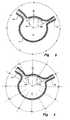
- Figures 2 and 3show a schematic cross-section of the aorta in the region of the renal arteries indicated by the arrow 35 in Figure 1 .
- the aorta 2has an aorta wall 11, while renal arteries 13 and 15 extend therefrom.
- the renal arteriesare depicted as being at the same level in the aorta, although generally there may be a longitudinal spacing between the left and right renal arteries, as is depicted in Figure 1 .
- a stent graft placed into an aortahas a diameter of perhaps 10 to 20 percent more than the diameter of the aorta and hence if the angular position of the fenestrations, one with respect the to other, were translated from the renal artery to the larger diameter stent graft and the stent graft released into the aorta, it is unlikely that it could be possible to ensure easily that the fenestrations open in apposition to the respective renal arteries because it is not possible to guarantee that the stent graft will open evenly within the aorta.
- the cross-section of the aorta in the region of the renal arteries as shown in Figure 2is obtained by radio-graphic techniques such as narrow slice enhanced computer tomography.
- a datum point 40 on the aortais selected. This is normally taken as the anterior point on the aorta as this can be most easily ascertained from radiography during deployment.
- the position of the renal arteries with respect to the datum point 40is then determined.
- the method usedis to assume that the aorta at the level of the renal arteries comprises a clock face with 12 o'clock at the selected datum point 40. This means that the centre of the renal artery 13 is at approximately 2 o 'clock and the centre of the renal artery 15 is at approximately 10:30.
- FIG 3another arrangement is used, in which degrees either side of the datum point 40 are used.
- the renal artery 13is at approximately 65 degrees from the datum point 40 to one side and the other renal artery 15 is approximately 40 degrees on the other side of the datum point.
- the inner circumference of the wall of the aortais calculated and the circumferential distance 42 from the datum point 40 to the centre of the renal artery 13 and the circumferential distance 44 from the datum point 40 to the centre of the renal artery 15 is calculated.
- a stent graftis then selected with a diameter which is 10 to 20 percent greater than the diameter of the aorta 2. For instance if the aorta has a diameter of 30 millimetres at the level of the renal arteries then a stent graft may be selected with a diameter of 36 millimetres at that level.
- a datum point 41(see Figure 4 ), which corresponds to the position, when the stent graft is deployed, of the selected datum point 40 on the aorta, is then selected on the stent graft and the circumferential distances 42 and 44 are measured on the surface of the stent graft in each direction from the datum point 41 to define centre points for each fenestration.
- Fenestrationsare then positioned around those centre points. It will be realised that a certain amount of latitude may be provided to ensure the fenestrations do not interfere with struts of stents on the surface of the stent graft.
- Diameter reducing tiesare then applied to the stent graft as will be discussed in more detail with respect to Figures 7, 8 and 9 .
- a stent grafthas been partially deployed into the aorta 2 with a sheath (not shown) retracted but the diameter reducing ties generally shown as 50 are still in place so that the overall diameter of the stent graft 52 is somewhat less that the diameter of the aorta 2.
- the stent graftcan be rotated and moved longitudinally.
- the stent graftis rotationally positioned so that the datum point 41 on the stent graft is coincident with the selected datum point 40 on the aorta.
- Observations of the position of the stent graft in the aortacan be made because radio opaque markers on the stent graft can be observed by suitable radiographic techniques.
- Fenestrations 54 and 56have been placed so that the distance 57 of the fenestration 54 from the datum point 41 and the distance 59 of the fenestration 56 to the datum point 41 are the same as the distances 42 and 44 respectively as discussed in relation to Figure 2 .
- the diameter reducing tiesare held in place by a release wire 60. It will be noted that the diameter reducing ties are as far as possible diametrically opposed to the two fenestrations 54 and 56 so that the diameter reduced portion 62 of the stent graft 52 is as far around from the renal arteries as possible.
- the actual positions of the fenestrations 54 and 56are shown by radio-opaque markers 63 either side of the fenestrations 54, 56.
- the release wirehas been withdrawn so that the diameter reducing ties 50 are released and the stent graft can engage the walls of the aorta.
- the corrugated portion of the stent graft which was involved with the temporary diameter reductiondoes not fully expand so that the circumferential distance between the fenestrations is equivalent to the circumferential distance of the wall of the aorta between the fenestrations and access to the renal arteries through the fenestrations is possible.
- Figure 6depicts a subsequent stage in the deployment process, where balloon expanded stents 66 and 68 have been deployed through the fenestrations 54, 56 and into the renal arteries 13 and 15, respectively, and expanded.
- Figures 7A and 7Bshow schematically one embodiment of diameter reducing tie.
- the graft material of a stent graftis not shown and only a portion of a self-expanding stent is shown stretched out flat.
- FIG 7Aa self-expanding stent 70 which would extend around the tubular body of a stent graft and be stitched to the stent graft material is shown.
- a release wire 72is stitched longitudinally along the stent graft, shown in more detail in Figure 9A , with a stitch 72a being exposed to the outside of the stent graft in the region of the self-expanding stent 70.
- a first suture thread 74is passed around the release wire 72 and extended out to one side of the release wire over the struts 76 of the stent graft to pass over three struts and to be looped around a fourth strut and into the graft material.
- the suture thread 74is then pulled tight and knotted as shown in Figure 7B with a knot 78, so that the struts between the release wire 72 and the knot 78 are pulled closer together.
- a similar actionis carried out to the other side of the release wire with a thread 80.
- the thread 80can either pass around the release wire 72 or is passed underneath the two strands of the thread 74 and over the release wire 72, passed over three struts and then it can be passed over three struts and looped around a fourth strut and into the graft material and pulled tight and knotted at 82.
- the reduction in distance between the release wire 72 and the knot 78may be from 50 to 75 percent. For instance if the distance is 15 millimetres round the circumference from the release wire 72 to the strut at which the knot 78 is placed, then this can be reduced to 5 millimetres. With two diameter reducing ties one to each side of the release wire 72, a total circumference reduction of 20 millimetres can be achieved which will change the diameter of a 36 millimetre stent graft to approximately 28 millimetres.
- thisis less than the diameter of the aorta, which means that the stent graft will still be manoeuvrable within the aorta while still mounted onto the deployment device but partially freed by the withdrawal of a containing sheath.
- double diameter reducing tiesmay be used, as depicted in Figures 8A and 8B .
- two release wires 90 and 92are used, parallel to each other and spaced by 6 or 7 struts of a self-expanding stent 91.
- the two release wires 90 and 92are stitched longitudinally along the stent graft, shown in more detail in Figure 9A , with stitches 90a and 92a being exposed to the outside of the stent graft in the region of the self-expanding stent 91.
- a first suture 93extends from one side of the release wire 90 and a second suture 94 extends to the other side of the release wire 90 and they are knotted off at 95 and 96.
- sutures 97 and 98are extended either side of the release wire 92 and are knotted off at 99 and 100.
- the knots 96 and 99go on either side of the same strut.
- Figures 9A , 9B and 9Cshow a stent graft with various stages of fitting and release of diameter reducing ties.
- Figure 9Ashows a more proximal portion of a composite stent graft for mounting into the aorta.
- the stent graftincludes a tubular body 120 with an internal zigzag self-expanding stent 122 at its proximal end and an exposed proximally extending stent 124 mounted to the proximal end of the tubular body 120. Further external self-expanding stents 126 are supplied along the length of the body to the distal end 128.
- the tubular body 120tapers at 130 so that it has a first selected diameter at the proximal end and a slightly smaller diameter further down the length of the tubular body.
- the first stageis the placement of release wires 132 and 134 which extend longitudinally along the tubular body and are stitched in and out of the tubular body. Stitches can be seen on the exterior of the tubular body in regions coinciding with the intermediate region of each of the exposed stents.
- a sutureis placed around the release wire, extended across about three struts of the zigzag stent 126 to strut 136 and pulled tight, as shown at 138 in Figure 9B .
- a suture 140is extended from the other direction from the release wire 132 for about three struts and then pulled tight.
- a similar extension of sutures in each direction from release wire 134is installed to compress the other side.
- the suture 142 which extends back towards the release wire 132is joined to the same strut 136 as the suture 138.
- the suture 144extends in the opposite direction from the release wire 134.
- Figure 9Bshows the stent graft mounted onto a deployment device with a pusher catheter 150 at one end and a nose cone capsule 152 into which the proximally extending stent 124 is received at the other end.
- Figure 9Cshows the stent graft still mounted onto the deployment device so that the exposed stent 124 is still received in the capsule 152 but the release wires have been withdrawn so that the diameter reducing ties are released. It will be noted that the sutures 140, 138, 142, and 144 remain on the outside of the stent graft. This is not a problem as they do not interfere with blood flow and may assist with adhesion of the stent graft onto the wall of the aorta.
- two sets of double diameter reducing tiesmay be used with one set of such ties and trigger wire placed anteriorily to the renal arteries and another set of such ties and trigger wire placed posteriorily to the renal arteries.
Landscapes
- Health & Medical Sciences (AREA)
- Gastroenterology & Hepatology (AREA)
- Pulmonology (AREA)
- Cardiology (AREA)
- Oral & Maxillofacial Surgery (AREA)
- Transplantation (AREA)
- Engineering & Computer Science (AREA)
- Biomedical Technology (AREA)
- Heart & Thoracic Surgery (AREA)
- Vascular Medicine (AREA)
- Life Sciences & Earth Sciences (AREA)
- Animal Behavior & Ethology (AREA)
- General Health & Medical Sciences (AREA)
- Public Health (AREA)
- Veterinary Medicine (AREA)
- Prostheses (AREA)
Description
- This invention relates to pre-operative sizing and assembly of a stent graft for deployment and to a stent graft with fenestrations.
- Throughout this specification the term distal with respect to a portion of the aorta, a deployment device or a prosthesis is the end of the aorta, deployment device or prosthesis further away in the direction of blood flow away from the heart and the term proximal means the portion of the aorta, deployment device or end of the prosthesis nearer to the heart. When applied to other vessels similar terms such as caudal and cranial should be understood.
- The teachings herein will be particularly discussed in relation to stent grafts for placement into the thoracoabdominal aorta for the treatment of aneurysms and more specifically in relation to juxtarenal placement. They are not, however, so restricted and may be applied to stent grafts for placement in any lumen of the human or animal body.
- The segment of aorta between the celiac and renal arteries is the best endowed with adventitial elastin, the most stable, and the last to dilate. Aneurysms of this area are associated with aneurysms of less stable areas in the descending thoracic aorta, infrarenal aorta, or both. Surgical repair of the thoracoabdominal aorta often involves wide exposure through long, multi-cavity incisions, followed by periods of visceral ischemia. Despite advances in surgical techniques and perioperative care, the mortality and morbidity rates remain high, especially in patients who are old, sick, or have already undergone open surgical repair of an adjacent segment of the aorta. In such cases, an endovascular alternative would be welcome, yet endovascular methods of thoracoabdominal and pararenal aortic repair have been slow to develop. The challenge has been to exclude the aortic aneurysm while maintaining flow to its visceral branches.
- It is roughly four years since two distinctly different approaches to this problem were reported. The two devices were: a bifurcated abdominal aortic stent-graft with fenestrations for the renal and superior mesenteric arteries, and a thoracoabdominal stent-graft with branches for the celiac, superior mesenteric and renal arteries. In recent years, the distinctions between fenestrated and multibranched stent-grafts have been blurred by the emergence of many hybrid devices with features such as Nitinol ringed fenestrations, externally cuffed fenestrations, internally cuffed fenestrations, external spiral cuffs and axially-oriented cuffs or branches, both external and internal. Each element has advantages and disadvantages, and each combination has a different role.
- There now exists a family of devices, which share several key features. In each of them, a barbed uncovered Z-stent anchors the proximal end, and a single proximal orifice attaches to a non-dilated segment of aorta (or previously inserted prosthesis). They all distribute blood through multiple branches, cuffs or holes (fenestrations), and they have series of Z-stents and Nitinol rings, providing support from one end of the stent-graft to the other.
- In cases of juxtarenal AAA, the rim of non-dilated infrarenal aorta is too short for secure haemostatic implantation of an unfenestrated stent-graft. There is only enough room in the neck for the proximal end of the proximal stent; the rest of this covered stent expands into the aneurysm, assuming a conical shape. Under these circumstances, there is insufficient apposition between the stent-graft and the aorta to achieve a reliable seal. Properly positioned fenestrations (holes) provide a route for flow through the stent-graft into the renal arteries, thereby allowing the proximal end of the stent-graft to be placed higher in the non-dilated pararenal aorta where it assumes a cylindrical shape. The dual goals of renal perfusion and aneurysm exclusion are achieved only when the fenestration is positioned precisely over the renal orifices, and the outer surface of the stent-graft around the fenestration is brought into close apposition with the inner surface of the aorta around the renal orifice. A typical fenestrated technique uses a bridging catheter, sheath or balloon to guide each fenestration to the corresponding renal orifice, and a bridging stent to hold it there. Stent-graft deployment has five main stages: extrusion of the half-open stent-graft, trans-graft renal artery catheterization, complete stent-graft expansion, renal stenting, and completion of the aortic exclusion with bifurcated extension into the iliac arteries.
- An exemplary stent-graft is disclosed in
WO 99/29262 - The three forms of fenestration in common use are the large fenestration, the scallop and the small fenestration. A large fenestration is used only when the target artery is well away from the aneurysm. No bridging stent is required, or even feasible, since one or more stent struts cross the orifice of a large fenestration. A scallop is essentially a large open-topped fenestration. In many cases, the presence of a scallop for the superior mesenteric artery allows sufficient separation (>15mm) between the proximal margin of the stent-graft and the middle of the renal orifices. Small fenestrations are commonly placed over both renal arteries, and held there by bridging stents. Stent struts cannot cross the orifice of a small fenestration. Small fenestrations are therefore confined to the lower halves of the triangular spaces between adjacent stent-struts.
- Localized juxtarenal aneurysms or pseudo-aneurysms require no more than a single cylindrical fenestrated stent-graft, but most cases of infrarenal aneurysm extend to the aortic bifurcation and require bilateral iliac outflow through a bifurcated stent-graft. The combination of a fenestrated proximal component with a bifurcated distal component is called a composite stent graft. Dividing the stent-graft into two components separates the two halves of the procedure. The operator need not be concerned about the position or orientation of the bifurcation while inserting the fenestrated proximal component, or about the position and location of the fenestrations while inserting the bifurcated distal component. The composite arrangement also separates the fenestrated proximal component from the large caudally directed hemodynamic forces that act mainly upon the bifurcation of the distal component. A small amount of slippage between the two is preferable to any proximal component migration, where even a few millimetres of movement would occlude both renal arteries. Indeed, the low rate of renal artery loss is testimony to the accuracy of stent-graft deployment and the stability of stent-graft attachment.
- The positioning of the fenestration is therefore very important to avoid renal occlusion.
- Positioning is further complicated because the diameter of a stent graft is deliberately made larger than the diameter into which it is to be placed to allow for accurate sealing against the vessel wall, possible errors in sizing and subsequent relaxation of the vessel wall. Hence, if fenestrations were placed in the same angular position relative to each other on a larger diameter graft than the vessel into which it is to be placed misalignment of the fenestrations with the branch arteries would occur.
- A further problem exists that upon deployment and release of the stent graft it is desirable that the graft open up from its confined delivery state to a released position under the influence of self-expanding stents with the fenestrations aligned with the renal arteries, for instance.
- The present invention seeks to provide an improved method of manufacturing a stent graft and to an improved stent graft.
- According to an aspect of the present invention, there is provided stent graft as specified in
claim 1. - The stent graft can further comprise a plurality of diameter reducing ties temporarily reducing the diameter, the diameter reducing ties being substantially diametrically opposed to the graft datum point.
- Thus, there can be provided a fenestrated stent-graft which is a highly customized device, which has a design based largely upon the findings of narrow slice, contrast-enhanced CT, and the expected orientation of the stent-graft. During preoperative sizing, each arterial orifice can be located relative to other landmarks up and down the long axis of the aorta, and oriented relative to other points on the same trans-axial section of the aorta. The orientation is described as an angle or as hours and minutes, as though the aorta were a clock face with anterior being 12:00. However, this does not translate directly into the fenestration's position on the fully opened stent-graft, because the stent-graft is not expected to open evenly. The constraining ties in the back of the stent-graft ensure that only the anterior surface opens completely. The posterior surface accommodates any over sizing. The renal fenestrations are therefore positioned so that the length of the arc between them on the anterior surface of the opened stent-graft matches the length of the arc between the arteries which they will oppose on the anterior surface of the aorta at that level.
- Thus, the preferred embodiments provide for pre-operative sizing and placement of the fenestrations on a stent graft and the assembly of a stent graft onto a deployment device.
- Some embodiments described herein also address the problem of assembly or mounting onto a deployment device to assist with accurate release upon deployment.
- Embodiments of the present invention are described below, by way of example only, with reference to the accompanying drawings, in which:
Figure 1 shows a schematic view of an aneurysed aorta with a bifurcated and fenestrated stent graft deployed into it;Figure 2 shows a schematic cross section of the aorta in the renal arteries and shows how the position of the renal arteries with respect to a datum position is determined using a clock face system;Figure 3 shows a similar embodiment to that ofFigure 2 except using a method determining the position using angles from a selected datum;Figure 4 shows a similar view to that ofFigures 2 and 3 but with a stent graft in a semi- contracted condition deployed in the aorta but not showing other features of the deployment device upon which the stent graft is deployed;Figure 5 shows a similar view to that ofFigure 4 except with the diameter reducing ties on the stent graft released;Figure 6 shows a similar view ofFigure 5 with side graft stents placed in the fenestrations;Figures 7A and 7B show schematically how one arrangement of a diameter reducing tie is applied to a stent graft;Figures 8A and 8B show an alternative embodiment of diameter reducing tie intended for use with a stent graft; andFigures 9A ,9B and9C show a stent graft in various stages of application and release of double diameter reducing ties on a stent graft.- Referring to
Figure 1 there is schematically shown anaorta 2 extending down to an aortic bifurcation at 3 and into twoiliac arteries aneurysm 9 defined by a bulge in theaorta wall 11 extends from near to theaortic bifurcation 3 nearly to therenal arteries - This embodiment provides a bifurcated stent graft having a longer leg for extending into one iliac artery and a shorter leg into which a leg extension may be deployed for the contralateral iliac artery but the teachings herein are not so limited and may also be used for a composite stent graft in which the fenestrations are in a proximal tubular portion of the composite stent graft and if necessary a further bifurcated portion of stent graft is used to extend down to the iliac arteries.
- As shown,
stent graft 20 has a proximally extending exposedstent 22, a proximalinternal stent 36 and a plurality ofexternal stents 38 along the length of its tubular body. - The
stent graft 20 has abifurcation 24 and along leg 27 extending down iliac artery 7and ashort leg 26 directed towardsiliac artery 5. Aleg extension 28 is connected into theshort leg 26 and extends down theiliac artery 5. Thestent graft 20 has a proximalinternal stent 36 and a plurality ofexternal stents 38 along the length of its tubular body. At therenal arteries - Methods of mounting a stent graft onto a deployment device and deployment of such a stent graft are described in
WO98/53761 - Although the renal arteries in
Figure 1 are depicted as extending laterally either side of the aorta, in fact the position of the renal arteries is very variable and they are sometimes closer together towards the anterior surface of the aorta and can be positioned more or less apart longitudinally. Figures 2 and 3 show a schematic cross-section of the aorta in the region of the renal arteries indicated by thearrow 35 inFigure 1 .- In
Figure 2 theaorta 2 has anaorta wall 11, whilerenal arteries Figure 1 . - In order to ensure accurate alignment between the fenestrations of a stent graft and the renal arteries it is desirable to place balloon expanded stents or self-expanding stent assemblies into the renal arteries from fenestrations in the stent graft placed into the aorta. Generally a stent graft placed into an aorta has a diameter of perhaps 10 to 20 percent more than the diameter of the aorta and hence if the angular position of the fenestrations, one with respect the to other, were translated from the renal artery to the larger diameter stent graft and the stent graft released into the aorta, it is unlikely that it could be possible to ensure easily that the fenestrations open in apposition to the respective renal arteries because it is not possible to guarantee that the stent graft will open evenly within the aorta.
- The cross-section of the aorta in the region of the renal arteries as shown in
Figure 2 is obtained by radio-graphic techniques such as narrow slice enhanced computer tomography. Adatum point 40 on the aorta is selected. This is normally taken as the anterior point on the aorta as this can be most easily ascertained from radiography during deployment. The position of the renal arteries with respect to thedatum point 40 is then determined. InFigure 2 the method used is to assume that the aorta at the level of the renal arteries comprises a clock face with 12 o'clock at the selecteddatum point 40. This means that the centre of therenal artery 13 is at approximately 2 o 'clock and the centre of therenal artery 15 is at approximately 10:30. - In
Figure 3 another arrangement is used, in which degrees either side of thedatum point 40 are used. In this case therenal artery 13 is at approximately 65 degrees from thedatum point 40 to one side and the otherrenal artery 15 is approximately 40 degrees on the other side of the datum point. - Next, knowing the diameter of the
actual aorta 2, the inner circumference of the wall of the aorta is calculated and thecircumferential distance 42 from thedatum point 40 to the centre of therenal artery 13 and thecircumferential distance 44 from thedatum point 40 to the centre of therenal artery 15 is calculated. - A stent graft is then selected with a diameter which is 10 to 20 percent greater than the diameter of the
aorta 2. For instance if the aorta has a diameter of 30 millimetres at the level of the renal arteries then a stent graft may be selected with a diameter of 36 millimetres at that level. A datum point 41 (seeFigure 4 ), which corresponds to the position, when the stent graft is deployed, of the selecteddatum point 40 on the aorta, is then selected on the stent graft and thecircumferential distances - Diameter reducing ties are then applied to the stent graft as will be discussed in more detail with respect to
Figures 7, 8 and9 . - For clarity the various components of the deployment device are not depicted in
Figures 4, 5 and 6 . - As depicted in
Figure 4 a stent graft has been partially deployed into theaorta 2 with a sheath (not shown) retracted but the diameter reducing ties generally shown as 50 are still in place so that the overall diameter of thestent graft 52 is somewhat less that the diameter of theaorta 2. At this stage the stent graft can be rotated and moved longitudinally. The stent graft is rotationally positioned so that the datum point 41 on the stent graft is coincident with the selecteddatum point 40 on the aorta. Observations of the position of the stent graft in the aorta can be made because radio opaque markers on the stent graft can be observed by suitable radiographic techniques. Fenestrations 54 and 56 have been placed so that thedistance 57 of thefenestration 54 from the datum point 41 and the distance 59 of thefenestration 56 to the datum point 41 are the same as thedistances Figure 2 . - The diameter reducing ties are held in place by a
release wire 60. It will be noted that the diameter reducing ties are as far as possible diametrically opposed to the two fenestrations 54 and 56 so that the diameter reducedportion 62 of thestent graft 52 is as far around from the renal arteries as possible. - The actual positions of the
fenestrations opaque markers 63 either side of thefenestrations - As shown in
Figure 5 the release wire has been withdrawn so that thediameter reducing ties 50 are released and the stent graft can engage the walls of the aorta. Generally the corrugated portion of the stent graft which was involved with the temporary diameter reduction does not fully expand so that the circumferential distance between the fenestrations is equivalent to the circumferential distance of the wall of the aorta between the fenestrations and access to the renal arteries through the fenestrations is possible. Figure 6 depicts a subsequent stage in the deployment process, where balloon expandedstents fenestrations renal arteries Figures 7A and 7B show schematically one embodiment of diameter reducing tie. In this drawing the graft material of a stent graft is not shown and only a portion of a self-expanding stent is shown stretched out flat.- As can be seen in
Figure 7A a self-expandingstent 70 which would extend around the tubular body of a stent graft and be stitched to the stent graft material is shown. Arelease wire 72 is stitched longitudinally along the stent graft, shown in more detail inFigure 9A , with astitch 72a being exposed to the outside of the stent graft in the region of the self-expandingstent 70. - A
first suture thread 74 is passed around therelease wire 72 and extended out to one side of the release wire over thestruts 76 of the stent graft to pass over three struts and to be looped around a fourth strut and into the graft material. Thesuture thread 74 is then pulled tight and knotted as shown inFigure 7B with aknot 78, so that the struts between therelease wire 72 and theknot 78 are pulled closer together. - A similar action is carried out to the other side of the release wire with a
thread 80. In this case thethread 80 can either pass around therelease wire 72 or is passed underneath the two strands of thethread 74 and over therelease wire 72, passed over three struts and then it can be passed over three struts and looped around a fourth strut and into the graft material and pulled tight and knotted at 82. - The reduction in distance between the
release wire 72 and theknot 78 may be from 50 to 75 percent. For instance if the distance is 15 millimetres round the circumference from therelease wire 72 to the strut at which theknot 78 is placed, then this can be reduced to 5 millimetres. With two diameter reducing ties one to each side of therelease wire 72, a total circumference reduction of 20 millimetres can be achieved which will change the diameter of a 36 millimetre stent graft to approximately 28 millimetres. In this example this is less than the diameter of the aorta, which means that the stent graft will still be manoeuvrable within the aorta while still mounted onto the deployment device but partially freed by the withdrawal of a containing sheath. - Where a greater amount of diameter reduction is desirable, double diameter reducing ties may be used, as depicted in
Figures 8A and 8B . In this embodiment tworelease wires stent 91. The tworelease wires Figure 9A , withstitches stent 91. Afirst suture 93 extends from one side of therelease wire 90 and asecond suture 94 extends to the other side of therelease wire 90 and they are knotted off at 95 and 96. Similarly sutures 97 and 98 are extended either side of therelease wire 92 and are knotted off at 99 and 100. Generally theknots - By using these double diameter reducing ties a reduction in circumference of up to 40 millimetres may be obtained for a 36 millimetre diameter stent graft, which will give a final diameter of approximately 24 millimetres. Once again, with this temporary reduction in diameter, movement of the stent graft for final positioning can be easily achieved.
Figures 9A ,9B and9C show a stent graft with various stages of fitting and release of diameter reducing ties.- As discussed above, diameter reducing ties are placed onto a stent graft requiring diameter reduction at a point substantially diametrically opposite to the fenestrations and hence in
Figures 9A ,9B and9C the fenestrations cannot be seen. Figure 9A shows a more proximal portion of a composite stent graft for mounting into the aorta. The stent graft includes atubular body 120 with an internal zigzag self-expandingstent 122 at its proximal end and an exposed proximally extendingstent 124 mounted to the proximal end of thetubular body 120. Further external self-expandingstents 126 are supplied along the length of the body to thedistal end 128. It will be noted thetubular body 120 tapers at 130 so that it has a first selected diameter at the proximal end and a slightly smaller diameter further down the length of the tubular body.- This embodiment will be discussed particularly in relation to installation of double diameter reducing ties. The first stage is the placement of
release wires zigzag stent 126 to strut 136 and pulled tight, as shown at 138 inFigure 9B . Similarly asuture 140 is extended from the other direction from therelease wire 132 for about three struts and then pulled tight. - A similar extension of sutures in each direction from
release wire 134 is installed to compress the other side. Thesuture 142 which extends back towards therelease wire 132 is joined to thesame strut 136 as thesuture 138. Thesuture 144 extends in the opposite direction from therelease wire 134. - This process is repeated with the other exposed
stents 126 and theinternal stent 122. In the case of theinternal stent 122 the sutures are inserted through the material of thetubular body 120 to go around the stents, where they are knotted but otherwise remain outside of the tubular body. This gives the result shown inFigure 9B , where the diameter of the stent graft is considerably reduced. Diameter reducing ties may be either placed along the entire length of the stent graft so that the stent graft remains manoeuvrable after its partial release or can be confined to only the parts of the stent graft that are larger in diameter than the vessel lumen into which it is to be placed. Figure 9B shows the stent graft mounted onto a deployment device with apusher catheter 150 at one end and anose cone capsule 152 into which theproximally extending stent 124 is received at the other end.Figure 9C shows the stent graft still mounted onto the deployment device so that the exposedstent 124 is still received in thecapsule 152 but the release wires have been withdrawn so that the diameter reducing ties are released. It will be noted that thesutures - In another arrangement, where space permits, two sets of double diameter reducing ties may be used with one set of such ties and trigger wire placed anteriorily to the renal arteries and another set of such ties and trigger wire placed posteriorily to the renal arteries.
- The above disclosure focusses on the method of pre-operative sizing and assembly of a stent graft to explain the teachings herein. The skilled person will readily appreciate the apparatus elements which will provide such a method, at least some these being in common use by physicians, such as the means for determining the datum points. Thus, there is no substantive description of such apparatus.
- Throughout this specification and the claims that follow unless the context requires otherwise, the words 'comprise' and 'include' and variations such as 'comprising' and 'including' will be understood to imply the inclusion of a stated integer or group of integers but not the exclusion of any other integer or group of integers.
Claims (4)
- A stent graft for placement in a body vessel, the body vessel having a measured diameter at the level of side branches of the vessel and the side branches being located circumferentially on an inner wall of the vessel by a measured distances from a vessel datum point, the stent graft including:a tubular body (20) of a biocompatible graft material and at least two fenestrations (54, 56) in the tubular body, the tubular body having a diameter of between 10 to 20% greater than the measured diameter of the body vessel in the region of the fenestrations (54, 56), the fenestrations being spaced circumferentially around the tubular body from a selected graft datum point (41) by the measured distance; anda temporary diameter reduction constraint arrangement provided at a position substantially diametrically opposed to the graft datum point, wherein the temporary diameter reduction constraint arrangement comprises at least one release wire (72) extending longitudinally along the tubular body and at least one circumferential thread (74, 80; 93, 94, 97, 98) engagable around the release wire and a portion of the stent graft circumferentially spaced a selected distance from the release wire and able to be drawn tight and tied to reduce the circumference and thereby the overall diameter of the stent graft.
- A stent graft as claimed in claim 1, wherein the vessel datum point (40) is an anterior point on the vessel and the graft datum point (41) is the anterior-most point on the stent graft.
- A stent graft as claimed in claim 1 or 2, comprising a plurality of diameter reducing ties being substantially diametrically opposed to the graft datum point.
- A deployment device including a stent graft as claimed in claim 1, 2 or 3.
Applications Claiming Priority (2)
| Application Number | Priority Date | Filing Date | Title |
|---|---|---|---|
| US70941105P | 2005-08-18 | 2005-08-18 | |
| EP06801982.7AEP1915106B1 (en) | 2005-08-18 | 2006-08-18 | Method of manufacturing fenestrated stent grafts |
Related Parent Applications (2)
| Application Number | Title | Priority Date | Filing Date |
|---|---|---|---|
| EP06801982.7ADivisionEP1915106B1 (en) | 2005-08-18 | 2006-08-18 | Method of manufacturing fenestrated stent grafts |
| EP06801982.7ADivision-IntoEP1915106B1 (en) | 2005-08-18 | 2006-08-18 | Method of manufacturing fenestrated stent grafts |
Publications (2)
| Publication Number | Publication Date |
|---|---|
| EP2497444A1 EP2497444A1 (en) | 2012-09-12 |
| EP2497444B1true EP2497444B1 (en) | 2015-09-16 |
Family
ID=37500179
Family Applications (3)
| Application Number | Title | Priority Date | Filing Date |
|---|---|---|---|
| EP06813626.6AActiveEP1922029B1 (en) | 2005-08-18 | 2006-08-18 | Assembly of stent grafts |
| EP12171060.2AActiveEP2497444B1 (en) | 2005-08-18 | 2006-08-18 | Design and assembly of fenestrated stent grafts |
| EP06801982.7AActiveEP1915106B1 (en) | 2005-08-18 | 2006-08-18 | Method of manufacturing fenestrated stent grafts |
Family Applications Before (1)
| Application Number | Title | Priority Date | Filing Date |
|---|---|---|---|
| EP06813626.6AActiveEP1922029B1 (en) | 2005-08-18 | 2006-08-18 | Assembly of stent grafts |
Family Applications After (1)
| Application Number | Title | Priority Date | Filing Date |
|---|---|---|---|
| EP06801982.7AActiveEP1915106B1 (en) | 2005-08-18 | 2006-08-18 | Method of manufacturing fenestrated stent grafts |
Country Status (6)
| Country | Link |
|---|---|
| US (2) | US9504555B2 (en) |
| EP (3) | EP1922029B1 (en) |
| JP (1) | JP5156936B2 (en) |
| AU (2) | AU2006280948B2 (en) |
| CA (2) | CA2619587C (en) |
| WO (2) | WO2007022526A1 (en) |
Families Citing this family (157)
| Publication number | Priority date | Publication date | Assignee | Title |
|---|---|---|---|---|
| US7147661B2 (en) | 2001-12-20 | 2006-12-12 | Boston Scientific Santa Rosa Corp. | Radially expandable stent |
| US7314484B2 (en)* | 2002-07-02 | 2008-01-01 | The Foundry, Inc. | Methods and devices for treating aneurysms |
| US11890181B2 (en)* | 2002-07-22 | 2024-02-06 | Tmt Systems, Inc. | Percutaneous endovascular apparatus for repair of aneurysms and arterial blockages |
| US8425549B2 (en) | 2002-07-23 | 2013-04-23 | Reverse Medical Corporation | Systems and methods for removing obstructive matter from body lumens and treating vascular defects |
| US9125733B2 (en)* | 2003-01-14 | 2015-09-08 | The Cleveland Clinic Foundation | Branched vessel endoluminal device |
| EP1922029B1 (en) | 2005-08-18 | 2014-11-19 | Cook Medical Technologies LLC | Assembly of stent grafts |
| AU2007240703C1 (en) | 2006-04-19 | 2012-06-14 | Cleveland Clinic Foundation | Twin bifurcated stent graft |
| WO2008042270A1 (en)* | 2006-09-28 | 2008-04-10 | Med Institute, Inc. | Endovascular delivery device |
| WO2008053469A2 (en)* | 2006-10-29 | 2008-05-08 | Alon Shalev | An extra-vascular wrapping for treating aneurysmatic aorta and methods thereof |
| ES2624595T3 (en) | 2007-03-05 | 2017-07-17 | Endospan Ltd | Bifurcated, supportive, expandable endoluminal grafts with multiple components and methods for use |
| US9717584B2 (en) | 2007-04-13 | 2017-08-01 | W. L. Gore & Associates, Inc. | Medical apparatus and method of making the same |
| US9642693B2 (en) | 2007-04-13 | 2017-05-09 | W. L. Gore & Associates, Inc. | Medical apparatus and method of making the same |
| US20080255678A1 (en)* | 2007-04-13 | 2008-10-16 | Cully Edward H | Medical apparatus and method of making the same |
| AU2008251804B2 (en) | 2007-05-11 | 2013-01-10 | Cook Incorporated | Stent grafts for the thoracic aorta |
| US8926680B2 (en) | 2007-11-12 | 2015-01-06 | Covidien Lp | Aneurysm neck bridging processes with revascularization systems methods and products thereby |
| US9198687B2 (en)* | 2007-10-17 | 2015-12-01 | Covidien Lp | Acute stroke revascularization/recanalization systems processes and products thereby |
| US8585713B2 (en) | 2007-10-17 | 2013-11-19 | Covidien Lp | Expandable tip assembly for thrombus management |
| US10123803B2 (en) | 2007-10-17 | 2018-11-13 | Covidien Lp | Methods of managing neurovascular obstructions |
| US8088140B2 (en) | 2008-05-19 | 2012-01-03 | Mindframe, Inc. | Blood flow restorative and embolus removal methods |
| US9220522B2 (en) | 2007-10-17 | 2015-12-29 | Covidien Lp | Embolus removal systems with baskets |
| US11337714B2 (en) | 2007-10-17 | 2022-05-24 | Covidien Lp | Restoring blood flow and clot removal during acute ischemic stroke |
| US8066757B2 (en) | 2007-10-17 | 2011-11-29 | Mindframe, Inc. | Blood flow restoration and thrombus management methods |
| US8142490B2 (en) | 2007-10-24 | 2012-03-27 | Cordis Corporation | Stent segments axially connected by thin film |
| CN101965162B (en) | 2007-12-15 | 2014-12-10 | 恩多斯潘有限公司 | Extra-vascular wrapping for treating aneurysmatic aorta in conjunction with endovascular stent-graft and methods thereof |
| US9226813B2 (en) | 2007-12-26 | 2016-01-05 | Cook Medical Technologies Llc | Low profile non-symmetrical stent |
| US8574284B2 (en) | 2007-12-26 | 2013-11-05 | Cook Medical Technologies Llc | Low profile non-symmetrical bare alignment stents with graft |
| GB2475494B (en)* | 2009-11-18 | 2011-11-23 | Cook William Europ | Stent graft and introducer assembly |
| US9180030B2 (en) | 2007-12-26 | 2015-11-10 | Cook Medical Technologies Llc | Low profile non-symmetrical stent |
| GB2476451A (en)* | 2009-11-19 | 2011-06-29 | Cook William Europ | Stent Graft |
| US20090192455A1 (en)* | 2008-01-07 | 2009-07-30 | David Ferrera | Novel enhanced ptna rapid exchange type of catheter system |
| WO2009105699A1 (en) | 2008-02-22 | 2009-08-27 | Endologix, Inc. | Design and method of placement of a graft or graft system |
| JP5457373B2 (en) | 2008-02-22 | 2014-04-02 | コヴィディエン リミテッド パートナーシップ | Device for blood flow recovery |
| WO2009108355A1 (en) | 2008-02-28 | 2009-09-03 | Medtronic, Inc. | Prosthetic heart valve systems |
| US20090248131A1 (en)* | 2008-03-31 | 2009-10-01 | Medtronic Vascular, Inc. | Covered Stent and Method of Making Same |
| JP5602129B2 (en)* | 2008-04-09 | 2014-10-08 | クック メディカル テクノロジーズ エルエルシー | Stent graft and device and attachment method |
| CN101977650A (en) | 2008-04-11 | 2011-02-16 | 曼德弗雷姆公司 | Monorail neural microcatheter for delivery of medical device for treatment of stroke, methods and products thereof |
| AU2009236062A1 (en)* | 2008-04-18 | 2009-10-22 | Cook Medical Technologies Llc | Branched vessel prosthesis |
| US10028747B2 (en) | 2008-05-01 | 2018-07-24 | Aneuclose Llc | Coils with a series of proximally-and-distally-connected loops for occluding a cerebral aneurysm |
| US10716573B2 (en) | 2008-05-01 | 2020-07-21 | Aneuclose | Janjua aneurysm net with a resilient neck-bridging portion for occluding a cerebral aneurysm |
| US20100305686A1 (en)* | 2008-05-15 | 2010-12-02 | Cragg Andrew H | Low-profile modular abdominal aortic aneurysm graft |
| CA2727000C (en) | 2008-06-04 | 2014-01-07 | Gore Enterprise Holdings, Inc. | Controlled deployable medical device and method of making the same |
| WO2009148607A1 (en)* | 2008-06-04 | 2009-12-10 | Gore Enterprise Holdings, Inc. | Controlled deployable medical device and method of making the same |
| US20100076470A1 (en) | 2008-09-22 | 2010-03-25 | Tyco Healthcare Group Lp | Methods and Devices for Sheath Compression |
| US8137398B2 (en)* | 2008-10-13 | 2012-03-20 | Medtronic Ventor Technologies Ltd | Prosthetic valve having tapered tip when compressed for delivery |
| GB2464978B (en)* | 2008-10-31 | 2010-10-20 | Cook William Europ | Introducer for deploying a stent graft in a curved lumen |
| AU2009200350B1 (en)* | 2009-02-02 | 2009-07-16 | Cook Incorporated | Preloaded stent graft delivery device |
| US20100274276A1 (en)* | 2009-04-22 | 2010-10-28 | Ricky Chow | Aneurysm treatment system, device and method |
| US20110054587A1 (en) | 2009-04-28 | 2011-03-03 | Endologix, Inc. | Apparatus and method of placement of a graft or graft system |
| CA3009244C (en) | 2009-06-23 | 2020-04-28 | Endospan Ltd. | Vascular prostheses for treating aneurysms |
| WO2011004374A1 (en) | 2009-07-09 | 2011-01-13 | Endospan Ltd. | Apparatus for closure of a lumen and methods of using the same |
| US9358140B1 (en) | 2009-11-18 | 2016-06-07 | Aneuclose Llc | Stent with outer member to embolize an aneurysm |
| US9757263B2 (en)* | 2009-11-18 | 2017-09-12 | Cook Medical Technologies Llc | Stent graft and introducer assembly |
| CN102740807B (en) | 2009-11-30 | 2015-11-25 | 恩多斯潘有限公司 | Multi-component stent-graft system for implantation into vessels with multiple branches |
| WO2011064784A1 (en)* | 2009-11-30 | 2011-06-03 | Biflow Medical Ltd. | Method of implanting a stent graft and creating a fenestration therein |
| US9358099B2 (en) | 2009-11-30 | 2016-06-07 | Biflow Medical Ltd. | Method of implanting a stent graft and creating a fenestration therein |
| EP2506799A4 (en) | 2009-12-01 | 2014-10-29 | Altura Medical Inc | Modular endograft devices and associated systems and methods |
| EP2509535B1 (en) | 2009-12-08 | 2016-12-07 | Endospan Ltd | Endovascular stent-graft system with fenestrated and crossing stent-grafts |
| WO2011080738A1 (en) | 2009-12-31 | 2011-07-07 | Endospan Ltd. | Endovascular flow direction indicator |
| US9468517B2 (en) | 2010-02-08 | 2016-10-18 | Endospan Ltd. | Thermal energy application for prevention and management of endoleaks in stent-grafts |
| AU2010201676B1 (en)* | 2010-04-23 | 2010-07-22 | Cook Medical Technologies Llc | Curve forming stent graft |
| US8894700B2 (en)* | 2010-05-31 | 2014-11-25 | Po-Jen Ko | Abdominal aortic stent |
| AU2010202487B1 (en) | 2010-06-15 | 2011-07-28 | Cook Incorporated | Pre-loaded multiport delivery device |
| US9101455B2 (en) | 2010-08-13 | 2015-08-11 | Cook Medical Technologies Llc | Preloaded wire for endoluminal device |
| CA2747610C (en) | 2010-08-13 | 2014-09-16 | Cook Medical Technologies Llc | Precannulated fenestration |
| WO2012040240A1 (en) | 2010-09-20 | 2012-03-29 | Altura Medical, Inc. | Stent graft delivery systems and associated methods |
| US20120109279A1 (en) | 2010-11-02 | 2012-05-03 | Endologix, Inc. | Apparatus and method of placement of a graft or graft system |
| US9566149B2 (en)* | 2010-11-16 | 2017-02-14 | W. L. Gore & Associates, Inc. | Devices and methods for in situ fenestration of a stent-graft at the site of a branch vessel |
| AU2010254599B1 (en) | 2010-12-15 | 2011-02-17 | Cook Incorporated | Hybrid Type A dissection device |
| US9198787B2 (en)* | 2010-12-31 | 2015-12-01 | Cook Medical Technologies Llc | Conformable prosthesis delivery system and method for deployment thereof |
| CA2826022A1 (en) | 2011-02-03 | 2012-08-09 | Endospan Ltd. | Implantable medical devices constructed of shape memory material |
| WO2012111006A1 (en) | 2011-02-17 | 2012-08-23 | Endospan Ltd. | Vascular bands and delivery systems therefor |
| WO2012117395A1 (en) | 2011-03-02 | 2012-09-07 | Endospan Ltd. | Reduced-strain extra- vascular ring for treating aortic aneurysm |
| EP3583916B1 (en) | 2011-04-28 | 2023-12-06 | Cook Medical Technologies LLC | Apparatus for facilitating deployment of an endoluminal prosthesis |
| EP2529705B1 (en)* | 2011-06-03 | 2019-02-06 | Cook Medical Technologies LLC | Introducer for deploying an implant |
| US8574287B2 (en) | 2011-06-14 | 2013-11-05 | Endospan Ltd. | Stents incorporating a plurality of strain-distribution locations |
| US8951298B2 (en) | 2011-06-21 | 2015-02-10 | Endospan Ltd. | Endovascular system with circumferentially-overlapping stent-grafts |
| US9254209B2 (en) | 2011-07-07 | 2016-02-09 | Endospan Ltd. | Stent fixation with reduced plastic deformation |
| US9839510B2 (en) | 2011-08-28 | 2017-12-12 | Endospan Ltd. | Stent-grafts with post-deployment variable radial displacement |
| US9427339B2 (en) | 2011-10-30 | 2016-08-30 | Endospan Ltd. | Triple-collar stent-graft |
| US8728148B2 (en) | 2011-11-09 | 2014-05-20 | Cook Medical Technologies Llc | Diameter reducing tie arrangement for endoluminal prosthesis |
| JP6227542B2 (en) | 2011-11-11 | 2017-11-08 | ボルトン メディカル インコーポレイテッド | Universal endovascular graft |
| CN106420107B (en) | 2011-11-16 | 2019-02-05 | 波顿医疗公司 | The device and method of reparation for aortic branch blood vessel |
| US9597204B2 (en) | 2011-12-04 | 2017-03-21 | Endospan Ltd. | Branched stent-graft system |
| US20130166015A1 (en) | 2011-12-22 | 2013-06-27 | Cook Medical Technologies Llc | Hybrid aortic arch replacement |
| EP2985007B1 (en) | 2011-12-22 | 2019-11-13 | Cook Medical Technologies LLC | Preloaded wire for endoluminal device |
| DE102012101103B3 (en) | 2012-02-10 | 2013-07-04 | Jotec Gmbh | Stentgraft with fixation elements and insertion system |
| US9402755B2 (en)* | 2012-03-13 | 2016-08-02 | W. L. Gore & Associates, Inc. | Sleeve retraction system |
| US8968384B2 (en)* | 2012-04-27 | 2015-03-03 | Medtronic Vascular, Inc. | Circumferentially constraining sutures for a stent-graft |
| WO2013171730A1 (en) | 2012-05-15 | 2013-11-21 | Endospan Ltd. | Stent-graft with fixation elements that are radially confined for delivery |
| CA2881535A1 (en) | 2012-08-10 | 2014-02-13 | Altura Medical, Inc. | Stent delivery systems and associated methods |
| AU2012258395B1 (en) | 2012-11-27 | 2013-03-28 | Cook Medical Technologies Llc | Assembly of stent grafts with diameter reducing ties |
| AU2012258394B1 (en)* | 2012-11-27 | 2013-03-07 | Cook Medical Technologies Llc | Stent graft having a closeable fenestration |
| EP2745813A1 (en) | 2012-12-18 | 2014-06-25 | Cook Medical Technologies LLC | Preloaded wire for endoluminal device |
| US10039657B2 (en) | 2012-12-21 | 2018-08-07 | CARDINAL HEALTH SWITZERLAND 515 GmbH | Cannulation guiding device for bifurcated stent and method of use |
| US10350096B2 (en)* | 2012-12-26 | 2019-07-16 | Cook Medical Technologies Llc | Expandable stent-graft system having diameter reducing connectors |
| US10154918B2 (en)* | 2012-12-28 | 2018-12-18 | Cook Medical Technologies Llc | Endoluminal prosthesis with fiber matrix |
| US9993360B2 (en) | 2013-01-08 | 2018-06-12 | Endospan Ltd. | Minimization of stent-graft migration during implantation |
| US9668892B2 (en) | 2013-03-11 | 2017-06-06 | Endospan Ltd. | Multi-component stent-graft system for aortic dissections |
| GB2511775A (en)* | 2013-03-12 | 2014-09-17 | Cook Medical Technologies Llc | Device and Method for Treating Vascular Dissections |
| US9545324B2 (en) | 2013-03-13 | 2017-01-17 | Cook Medical Technologies Llc | Pre-loaded iliac branch device and methods of deployment |
| WO2014144809A1 (en) | 2013-03-15 | 2014-09-18 | Altura Medical, Inc. | Endograft device delivery systems and associated methods |
| DE102013004625A1 (en) | 2013-03-16 | 2014-09-18 | Universitätsklinikum Freiburg | Bioresorbable stent |
| CN105979913B (en)* | 2013-06-05 | 2018-09-14 | 俄奥梯科创新有限公司 | Variable sunken holder(VDS)It is grafted component with waveform |
| AU2013206465B1 (en)* | 2013-06-18 | 2014-01-16 | Cook Medical Technologies Llc | Endovascular graft with an expanded lumen at a bifurcation |
| AU2013206712B1 (en) | 2013-07-03 | 2013-11-28 | Cook Medical Technologies Llc | Endovascular graft having a cannulation pocket |
| WO2015061669A1 (en)* | 2013-10-24 | 2015-04-30 | The Cleveland Clinic Foundation | Branched vessel prosthesis for repair of a failed stent graft |
| WO2015075708A1 (en) | 2013-11-19 | 2015-05-28 | Endospan Ltd. | Stent system with radial-expansion locking |
| BR112017005790A2 (en) | 2014-09-23 | 2018-01-30 | Bolton Medical Inc | vascular repair devices and methods of use |
| CN106029005B (en) | 2014-12-18 | 2018-01-19 | 恩都思潘有限公司 | The Endovascular stent-graft of horizontal conduit with tired resistance |
| EP3037072B1 (en) | 2014-12-23 | 2020-04-22 | Cook Medical Technologies LLC | Introducer with side opening |
| US10092428B2 (en) | 2014-12-30 | 2018-10-09 | Cook Medical Technologies Llc | Low profile prosthesis delivery device |
| AU2016207060B2 (en)* | 2015-01-14 | 2018-10-18 | Cook Medical Technologies Llc | Suture and wire stent deployment system |
| JP6436572B2 (en)* | 2015-03-13 | 2018-12-12 | テルモ株式会社 | Medical device |
| WO2017004265A1 (en) | 2015-06-30 | 2017-01-05 | Endologix, Inc. | Locking assembly for coupling guidewire to delivery system |
| JP6543119B2 (en) | 2015-07-10 | 2019-07-10 | 有限会社Ptmc研究所 | Stent graft |
| US10034785B1 (en) | 2015-10-13 | 2018-07-31 | W. L. Gore & Associates, Inc. | Single site access aortic aneurysm repair method |
| US10188538B2 (en) | 2015-12-30 | 2019-01-29 | Cook Medical Technologies Llc | Hybrid trigger wire for endografts |
| US10610393B2 (en) | 2016-03-24 | 2020-04-07 | Cook Medical Technologies Llc | Wire retention and release mechanisms |
| ES2830748T3 (en) | 2016-04-05 | 2021-06-04 | Bolton Medical Inc | Stent grafting with internal tunnels and fenestrations |
| ES2905193T3 (en) | 2016-05-25 | 2022-04-07 | Bolton Medical Inc | Stent grafts for the treatment of aneurysms |
| EP3903732B1 (en) | 2016-06-13 | 2025-07-30 | Bolton Medical, Inc. | Devices for reinforcing fenestrations in prosthetic implants |
| US20180021155A1 (en) | 2016-07-21 | 2018-01-25 | Cook Medical Technologies Llc | Tapered body aaa graft |
| AU2017306141A1 (en) | 2016-08-02 | 2019-03-07 | Aortica Corporation | Systems, devices, and methods for coupling a prosthetic implant to a fenestrated body |
| US10772751B2 (en) | 2016-09-09 | 2020-09-15 | Cook Medical Technologies Llc | Fenestrated endoluminal prosthesis and system and method of deployment thereof |
| US11191632B2 (en) | 2016-11-10 | 2021-12-07 | Cook Medical Technologies Llc | Temporary diameter reduction constraint arrangement for a stent graft in combination with a stent graft |
| EP3320881B1 (en) | 2016-11-10 | 2019-09-04 | Cook Medical Technologies LLC | Diameter reduction constraint arrangement for a stent graft in combination with a stent graft |
| US10433993B2 (en) | 2017-01-20 | 2019-10-08 | Medtronic Vascular, Inc. | Valve prosthesis having a radially-expandable sleeve integrated thereon for delivery and prevention of paravalvular leakage |
| WO2018156847A1 (en) | 2017-02-24 | 2018-08-30 | Bolton Medical, Inc. | Delivery system and method to radially constrict a stent graft |
| EP3932373B1 (en) | 2017-02-24 | 2022-12-21 | Bolton Medical, Inc. | Delivery system for radially constricting a stent graft |
| ES2863978T3 (en) | 2017-02-24 | 2021-10-13 | Bolton Medical Inc | System for radially constricting a stent graft |
| WO2018156850A1 (en) | 2017-02-24 | 2018-08-30 | Bolton Medical, Inc. | Stent graft with fenestration lock |
| ES2954897T3 (en) | 2017-02-24 | 2023-11-27 | Bolton Medical Inc | Constrained Wrap Stent Graft Delivery System |
| WO2018156849A1 (en) | 2017-02-24 | 2018-08-30 | Bolton Medical, Inc. | Vascular prosthesis with fenestration ring and methods of use |
| WO2018156851A1 (en) | 2017-02-24 | 2018-08-30 | Bolton Medical, Inc. | Vascular prosthesis with moveable fenestration |
| EP3534837A1 (en) | 2017-02-24 | 2019-09-11 | Bolton Medical, Inc. | Constrainable stent graft, delivery system and methods of use |
| WO2018156848A1 (en) | 2017-02-24 | 2018-08-30 | Bolton Medical, Inc. | Vascular prosthesis with crimped adapter and methods of use |
| WO2018156854A1 (en) | 2017-02-24 | 2018-08-30 | Bolton Medical, Inc. | Radially adjustable stent graft delivery system |
| US10709541B2 (en)* | 2017-04-28 | 2020-07-14 | Cook Medical Technologies Llc | Systems and methods for adjusting the diameter of an endoluminal prosthesis and an endoluminal prosthesis configured for the same |
| JP7271510B2 (en) | 2017-09-25 | 2023-05-11 | ボルトン メディカル インコーポレイテッド | Systems, devices and methods for coupling prosthetic implants to fenestrated bodies |
| CN110121319B (en)* | 2017-10-31 | 2023-05-09 | 波顿医疗公司 | Distal torque component, delivery system, and method of use thereof |
| US11096810B2 (en) | 2017-11-29 | 2021-08-24 | Cook Medical Technologies Llc | Preloaded pusher tip for endografts |
| WO2019108217A1 (en) | 2017-12-01 | 2019-06-06 | C.R. Bard, Inc. | Adjustable vascular graft for custom inner diameter reduction and related methods |
| EP3494936A1 (en) | 2017-12-05 | 2019-06-12 | Cook Medical Technologies LLC | Endograft delivery device assembly |
| CN109984862B (en)* | 2017-12-29 | 2025-10-03 | 杭州唯强医疗科技有限公司 | Aortic stent graft capable of step-by-step release |
| EP3508172B1 (en) | 2018-01-03 | 2020-08-19 | Cook Medical Technologies LLC | Pre-loaded multiport delivery device |
| JP7569219B2 (en)* | 2018-05-31 | 2024-10-17 | エンドロジックス リミテッド ライアビリティ カンパニー | STENT GRAFT SYSTEM HAVING CONSTRAINTS IN A CHANNEL AND METHOD THEREOF - Patent application |
| WO2019232263A1 (en)* | 2018-05-31 | 2019-12-05 | Endologix, Inc. | Systems and methods with anchor device for fixation of filling structures in blood vessels |
| US11963894B2 (en)* | 2018-12-18 | 2024-04-23 | Lifetech Scientific (Shenzhen) Co., Ltd. | Lumen stent and implant |
| CN111329634B (en)* | 2018-12-18 | 2024-07-16 | 先健科技(深圳)有限公司 | Implant |
| DE112020000296A5 (en) | 2019-01-29 | 2021-09-30 | Aggion Gmbh | VASCULAR PROSTHESIS FOR TREATMENT OF ANEURYSM, IN PARTICULAR AORTIC ANEURYSM |
| AU2019203004B1 (en) | 2019-04-30 | 2019-09-12 | Cook Medical Technologies Llc | A line pull assembly for a prosthetic delivery device |
| DE102019121930A1 (en)* | 2019-08-14 | 2021-02-18 | Jotec Gmbh | Vascular prosthesis |
| WO2021152669A1 (en)* | 2020-01-27 | 2021-08-05 | オリンパス株式会社 | Cover stent |
| GB2605559B (en) | 2021-01-07 | 2023-04-05 | Cook Medical Technologies Llc | Stent graft |
| AU2021201336B1 (en) | 2021-03-02 | 2021-07-15 | Cook Medical Technologies Llc | A constraint arrangement for a stent-graft loaded onto a delivery system |
| CN113274166B (en)* | 2021-05-10 | 2023-12-08 | 杭州唯强医疗科技有限公司 | Tectorial membrane support and conveying system |
| CN115869105B (en)* | 2021-08-24 | 2025-08-12 | 先健科技(深圳)有限公司 | Lumen stent |
Citations (1)
| Publication number | Priority date | Publication date | Assignee | Title |
|---|---|---|---|---|
| US20060004433A1 (en)* | 2004-06-16 | 2006-01-05 | Cook Incorporated | Thoracic deployment device and stent graft |
Family Cites Families (35)
| Publication number | Priority date | Publication date | Assignee | Title |
|---|---|---|---|---|
| US5693083A (en)* | 1983-12-09 | 1997-12-02 | Endovascular Technologies, Inc. | Thoracic graft and delivery catheter |
| CH678393A5 (en)* | 1989-01-26 | 1991-09-13 | Ulrich Prof Dr Med Sigwart | |
| US5387235A (en)* | 1991-10-25 | 1995-02-07 | Cook Incorporated | Expandable transluminal graft prosthesis for repair of aneurysm |
| US5456713A (en)* | 1991-10-25 | 1995-10-10 | Cook Incorporated | Expandable transluminal graft prosthesis for repairs of aneurysm and method for implanting |
| CA2081424C (en)* | 1991-10-25 | 2008-12-30 | Timothy A. Chuter | Expandable transluminal graft prosthesis for repair of aneurysm |
| US5587728A (en) | 1994-04-29 | 1996-12-24 | International Business Machines Corporation | Optical feedback printer |
| US6015429A (en)* | 1994-09-08 | 2000-01-18 | Gore Enterprise Holdings, Inc. | Procedures for introducing stents and stent-grafts |
| WO1996036297A1 (en)* | 1995-05-19 | 1996-11-21 | Kanji Inoue | Transplantation instrument, method of bending same and method of transplanting same |
| US6929659B2 (en)* | 1995-11-07 | 2005-08-16 | Scimed Life Systems, Inc. | Method of preventing the dislodgment of a stent-graft |
| US6042605A (en)* | 1995-12-14 | 2000-03-28 | Gore Enterprose Holdings, Inc. | Kink resistant stent-graft |
| US5843158A (en)* | 1996-01-05 | 1998-12-01 | Medtronic, Inc. | Limited expansion endoluminal prostheses and methods for their use |
| US6878161B2 (en)* | 1996-01-05 | 2005-04-12 | Medtronic Vascular, Inc. | Stent graft loading and deployment device and method |
| ATE290832T1 (en)* | 1996-01-05 | 2005-04-15 | Medtronic Inc | EXPANDABLE ENDOLUMINAL PROSTHESES |
| US6551350B1 (en)* | 1996-12-23 | 2003-04-22 | Gore Enterprise Holdings, Inc. | Kink resistant bifurcated prosthesis |
| US6352561B1 (en)* | 1996-12-23 | 2002-03-05 | W. L. Gore & Associates | Implant deployment apparatus |
| AUPO700897A0 (en) | 1997-05-26 | 1997-06-19 | William A Cook Australia Pty Ltd | A method and means of deploying a graft |
| US5984955A (en)* | 1997-09-11 | 1999-11-16 | Wisselink; Willem | System and method for endoluminal grafting of bifurcated or branched vessels |
| AUPP083597A0 (en)* | 1997-12-10 | 1998-01-08 | William A Cook Australia Pty Ltd | Endoluminal aortic stents |
| US6395018B1 (en)* | 1998-02-09 | 2002-05-28 | Wilfrido R. Castaneda | Endovascular graft and process for bridging a defect in a main vessel near one of more branch vessels |
| US6350277B1 (en)* | 1999-01-15 | 2002-02-26 | Scimed Life Systems, Inc. | Stents with temporary retaining bands |
| US7018401B1 (en)* | 1999-02-01 | 2006-03-28 | Board Of Regents, The University Of Texas System | Woven intravascular devices and methods for making the same and apparatus for delivery of the same |
| US6287333B1 (en)* | 1999-03-15 | 2001-09-11 | Angiodynamics, Inc. | Flexible stent |
| JP4138144B2 (en)* | 1999-03-31 | 2008-08-20 | テルモ株式会社 | Intraluminal indwelling |
| US6381350B1 (en)* | 1999-07-02 | 2002-04-30 | The Cleveland Clinic Foundation | Intravascular ultrasonic analysis using active contour method and system |
| JP2001186326A (en)* | 1999-12-27 | 2001-07-06 | Ricoh Co Ltd | Image tampering verification data embedding method, image tampering verification method, image tampering verification device, and recording medium |
| US20020193872A1 (en)* | 2001-06-18 | 2002-12-19 | Trout Hugh H. | Prosthetic graft assembly and method of use |
| AUPR847301A0 (en)* | 2001-10-26 | 2001-11-15 | Cook Incorporated | Endoluminal prostheses for curved lumens |
| CA2495155A1 (en)* | 2002-08-15 | 2004-02-26 | Gmp Cardiac Care, Inc. | Stent-graft with rails |
| AU2002951147A0 (en) | 2002-09-02 | 2002-09-19 | Cook Incorporated | Branch grafting device and method |
| US6905468B2 (en)* | 2002-09-18 | 2005-06-14 | Diagnostic Ultrasound Corporation | Three-dimensional system for abdominal aortic aneurysm evaluation |
| EP1405613B1 (en) | 2002-10-04 | 2006-03-22 | Sorin Biomedica Cardio S.R.L. | An implant device for treating aneurisms of the abdominal aorta |
| US7324675B2 (en)* | 2002-11-27 | 2008-01-29 | The Board Of Trustees Of The Leland Stanford Junior University | Quantification of aortoiliac endoluminal irregularity |
| EP1922029B1 (en)* | 2005-08-18 | 2014-11-19 | Cook Medical Technologies LLC | Assembly of stent grafts |
| AU2008251804B2 (en)* | 2007-05-11 | 2013-01-10 | Cook Incorporated | Stent grafts for the thoracic aorta |
| AU2010201676B1 (en)* | 2010-04-23 | 2010-07-22 | Cook Medical Technologies Llc | Curve forming stent graft |
- 2006
- 2006-08-18EPEP06813626.6Apatent/EP1922029B1/enactiveActive
- 2006-08-18AUAU2006280948Apatent/AU2006280948B2/enactiveActive
- 2006-08-18CACA2619587Apatent/CA2619587C/enactiveActive
- 2006-08-18EPEP12171060.2Apatent/EP2497444B1/enactiveActive
- 2006-08-18USUS11/507,115patent/US9504555B2/enactiveActive
- 2006-08-18EPEP06801982.7Apatent/EP1915106B1/enactiveActive
- 2006-08-18USUS11/507,247patent/US8172895B2/enactiveActive
- 2006-08-18CACA2619585Apatent/CA2619585C/enactiveActive
- 2006-08-18WOPCT/US2006/032683patent/WO2007022526A1/enactiveApplication Filing
- 2006-08-18WOPCT/US2006/032562patent/WO2007022495A1/enactiveApplication Filing
- 2006-08-18AUAU2006279305Apatent/AU2006279305B2/enactiveActive
- 2006-08-18JPJP2008527206Apatent/JP5156936B2/enactiveActive
Patent Citations (1)
| Publication number | Priority date | Publication date | Assignee | Title |
|---|---|---|---|---|
| US20060004433A1 (en)* | 2004-06-16 | 2006-01-05 | Cook Incorporated | Thoracic deployment device and stent graft |
Also Published As
| Publication number | Publication date |
|---|---|
| JP2009504349A (en) | 2009-02-05 |
| CA2619585C (en) | 2014-04-29 |
| JP2009504352A (en) | 2009-02-05 |
| AU2006279305A1 (en) | 2007-02-22 |
| US8172895B2 (en) | 2012-05-08 |
| JP5156936B2 (en) | 2013-03-06 |
| CA2619587A1 (en) | 2007-02-22 |
| US9504555B2 (en) | 2016-11-29 |
| AU2006280948B2 (en) | 2011-10-27 |
| JP5267124B2 (en) | 2013-08-21 |
| CA2619587C (en) | 2014-06-10 |
| WO2007022495A1 (en) | 2007-02-22 |
| US20070043425A1 (en) | 2007-02-22 |
| EP2497444A1 (en) | 2012-09-12 |
| EP1915106A1 (en) | 2008-04-30 |
| CA2619585A1 (en) | 2007-02-22 |
| WO2007022526A1 (en) | 2007-02-22 |
| AU2006279305B2 (en) | 2011-07-21 |
| EP1915106B1 (en) | 2018-04-04 |
| EP1922029A1 (en) | 2008-05-21 |
| AU2006280948A1 (en) | 2007-02-22 |
| US20070142896A1 (en) | 2007-06-21 |
| EP1922029B1 (en) | 2014-11-19 |
Similar Documents
| Publication | Publication Date | Title |
|---|---|---|
| EP2497444B1 (en) | Design and assembly of fenestrated stent grafts | |
| US6918926B2 (en) | System for transrenal/intraostial fixation of endovascular prosthesis | |
| US9974674B2 (en) | Branch vessel prothesis with positional indicator system and method | |
| AU738826B2 (en) | Endovascular prosthetic device, and method of use | |
| US6129756A (en) | Biluminal endovascular graft system | |
| US7029496B2 (en) | Interlocking endoluminal device | |
| US20030204249A1 (en) | Endovascular stent graft and fixation cuff | |
| US20250032242A1 (en) | Endoluminal prosthesis having a curved side tube and related methods | |
| JP5267124B6 (en) | Temporary diameter reduction restriction arrangement for stent graft and temporary diameter reduction restriction method | |
| PL222867B1 (en) | Intravascular system for placing and securing autogenous vascular prosthesis and a method for affixing autogenous vascular prosthesis |
Legal Events
| Date | Code | Title | Description |
|---|---|---|---|
| PUAI | Public reference made under article 153(3) epc to a published international application that has entered the european phase | Free format text:ORIGINAL CODE: 0009012 | |
| 17P | Request for examination filed | Effective date:20120606 | |
| AC | Divisional application: reference to earlier application | Ref document number:1915106 Country of ref document:EP Kind code of ref document:P | |
| AK | Designated contracting states | Kind code of ref document:A1 Designated state(s):AT BE BG CH CY CZ DE DK EE ES FI FR GB GR HU IE IS IT LI LT LU LV MC NL PL PT RO SE SI SK TR | |
| 17Q | First examination report despatched | Effective date:20121221 | |
| RAP1 | Party data changed (applicant data changed or rights of an application transferred) | Owner name:COOK MEDICAL TECHNOLOGIES LLC | |
| GRAP | Despatch of communication of intention to grant a patent | Free format text:ORIGINAL CODE: EPIDOSNIGR1 | |
| INTG | Intention to grant announced | Effective date:20150519 | |
| GRAS | Grant fee paid | Free format text:ORIGINAL CODE: EPIDOSNIGR3 | |
| GRAA | (expected) grant | Free format text:ORIGINAL CODE: 0009210 | |
| AC | Divisional application: reference to earlier application | Ref document number:1915106 Country of ref document:EP Kind code of ref document:P | |
| AK | Designated contracting states | Kind code of ref document:B1 Designated state(s):AT BE BG CH CY CZ DE DK EE ES FI FR GB GR HU IE IS IT LI LT LU LV MC NL PL PT RO SE SI SK TR | |
| REG | Reference to a national code | Ref country code:GB Ref legal event code:FG4D | |
| REG | Reference to a national code | Ref country code:CH Ref legal event code:EP | |
| REG | Reference to a national code | Ref country code:IE Ref legal event code:FG4D | |
| REG | Reference to a national code | Ref country code:AT Ref legal event code:REF Ref document number:749175 Country of ref document:AT Kind code of ref document:T Effective date:20151015 | |
| REG | Reference to a national code | Ref country code:DE Ref legal event code:R096 Ref document number:602006046718 Country of ref document:DE | |
| REG | Reference to a national code | Ref country code:NL Ref legal event code:MP Effective date:20150916 | |
| PG25 | Lapsed in a contracting state [announced via postgrant information from national office to epo] | Ref country code:GR Free format text:LAPSE BECAUSE OF FAILURE TO SUBMIT A TRANSLATION OF THE DESCRIPTION OR TO PAY THE FEE WITHIN THE PRESCRIBED TIME-LIMIT Effective date:20151217 Ref country code:LT Free format text:LAPSE BECAUSE OF FAILURE TO SUBMIT A TRANSLATION OF THE DESCRIPTION OR TO PAY THE FEE WITHIN THE PRESCRIBED TIME-LIMIT Effective date:20150916 Ref country code:FI Free format text:LAPSE BECAUSE OF FAILURE TO SUBMIT A TRANSLATION OF THE DESCRIPTION OR TO PAY THE FEE WITHIN THE PRESCRIBED TIME-LIMIT Effective date:20150916 Ref country code:LV Free format text:LAPSE BECAUSE OF FAILURE TO SUBMIT A TRANSLATION OF THE DESCRIPTION OR TO PAY THE FEE WITHIN THE PRESCRIBED TIME-LIMIT Effective date:20150916 | |
| REG | Reference to a national code | Ref country code:LT Ref legal event code:MG4D | |
| REG | Reference to a national code | Ref country code:AT Ref legal event code:MK05 Ref document number:749175 Country of ref document:AT Kind code of ref document:T Effective date:20150916 | |
| PG25 | Lapsed in a contracting state [announced via postgrant information from national office to epo] | Ref country code:SE Free format text:LAPSE BECAUSE OF FAILURE TO SUBMIT A TRANSLATION OF THE DESCRIPTION OR TO PAY THE FEE WITHIN THE PRESCRIBED TIME-LIMIT Effective date:20150916 | |
| PG25 | Lapsed in a contracting state [announced via postgrant information from national office to epo] | Ref country code:NL Free format text:LAPSE BECAUSE OF FAILURE TO SUBMIT A TRANSLATION OF THE DESCRIPTION OR TO PAY THE FEE WITHIN THE PRESCRIBED TIME-LIMIT Effective date:20150916 | |
| PG25 | Lapsed in a contracting state [announced via postgrant information from national office to epo] | Ref country code:EE Free format text:LAPSE BECAUSE OF FAILURE TO SUBMIT A TRANSLATION OF THE DESCRIPTION OR TO PAY THE FEE WITHIN THE PRESCRIBED TIME-LIMIT Effective date:20150916 Ref country code:SK Free format text:LAPSE BECAUSE OF FAILURE TO SUBMIT A TRANSLATION OF THE DESCRIPTION OR TO PAY THE FEE WITHIN THE PRESCRIBED TIME-LIMIT Effective date:20150916 Ref country code:IS Free format text:LAPSE BECAUSE OF FAILURE TO SUBMIT A TRANSLATION OF THE DESCRIPTION OR TO PAY THE FEE WITHIN THE PRESCRIBED TIME-LIMIT Effective date:20160116 Ref country code:CZ Free format text:LAPSE BECAUSE OF FAILURE TO SUBMIT A TRANSLATION OF THE DESCRIPTION OR TO PAY THE FEE WITHIN THE PRESCRIBED TIME-LIMIT Effective date:20150916 Ref country code:ES Free format text:LAPSE BECAUSE OF FAILURE TO SUBMIT A TRANSLATION OF THE DESCRIPTION OR TO PAY THE FEE WITHIN THE PRESCRIBED TIME-LIMIT Effective date:20150916 Ref country code:IT Free format text:LAPSE BECAUSE OF FAILURE TO SUBMIT A TRANSLATION OF THE DESCRIPTION OR TO PAY THE FEE WITHIN THE PRESCRIBED TIME-LIMIT Effective date:20150916 | |
| PG25 | Lapsed in a contracting state [announced via postgrant information from national office to epo] | Ref country code:PT Free format text:LAPSE BECAUSE OF FAILURE TO SUBMIT A TRANSLATION OF THE DESCRIPTION OR TO PAY THE FEE WITHIN THE PRESCRIBED TIME-LIMIT Effective date:20160118 Ref country code:RO Free format text:LAPSE BECAUSE OF FAILURE TO SUBMIT A TRANSLATION OF THE DESCRIPTION OR TO PAY THE FEE WITHIN THE PRESCRIBED TIME-LIMIT Effective date:20150916 Ref country code:AT Free format text:LAPSE BECAUSE OF FAILURE TO SUBMIT A TRANSLATION OF THE DESCRIPTION OR TO PAY THE FEE WITHIN THE PRESCRIBED TIME-LIMIT Effective date:20150916 Ref country code:PL Free format text:LAPSE BECAUSE OF FAILURE TO SUBMIT A TRANSLATION OF THE DESCRIPTION OR TO PAY THE FEE WITHIN THE PRESCRIBED TIME-LIMIT Effective date:20150916 | |
| REG | Reference to a national code | Ref country code:DE Ref legal event code:R097 Ref document number:602006046718 Country of ref document:DE | |
| PLBE | No opposition filed within time limit | Free format text:ORIGINAL CODE: 0009261 | |
| STAA | Information on the status of an ep patent application or granted ep patent | Free format text:STATUS: NO OPPOSITION FILED WITHIN TIME LIMIT | |
| 26N | No opposition filed | Effective date:20160617 | |
| PG25 | Lapsed in a contracting state [announced via postgrant information from national office to epo] | Ref country code:DK Free format text:LAPSE BECAUSE OF FAILURE TO SUBMIT A TRANSLATION OF THE DESCRIPTION OR TO PAY THE FEE WITHIN THE PRESCRIBED TIME-LIMIT Effective date:20150916 | |
| PG25 | Lapsed in a contracting state [announced via postgrant information from national office to epo] | Ref country code:SI Free format text:LAPSE BECAUSE OF FAILURE TO SUBMIT A TRANSLATION OF THE DESCRIPTION OR TO PAY THE FEE WITHIN THE PRESCRIBED TIME-LIMIT Effective date:20150916 | |
| PG25 | Lapsed in a contracting state [announced via postgrant information from national office to epo] | Ref country code:BE Free format text:LAPSE BECAUSE OF FAILURE TO SUBMIT A TRANSLATION OF THE DESCRIPTION OR TO PAY THE FEE WITHIN THE PRESCRIBED TIME-LIMIT Effective date:20150916 | |
| PG25 | Lapsed in a contracting state [announced via postgrant information from national office to epo] | Ref country code:MC Free format text:LAPSE BECAUSE OF FAILURE TO SUBMIT A TRANSLATION OF THE DESCRIPTION OR TO PAY THE FEE WITHIN THE PRESCRIBED TIME-LIMIT Effective date:20150916 | |
| REG | Reference to a national code | Ref country code:CH Ref legal event code:PL | |
| PG25 | Lapsed in a contracting state [announced via postgrant information from national office to epo] | Ref country code:LI Free format text:LAPSE BECAUSE OF NON-PAYMENT OF DUE FEES Effective date:20160831 Ref country code:CH Free format text:LAPSE BECAUSE OF NON-PAYMENT OF DUE FEES Effective date:20160831 | |
| REG | Reference to a national code | Ref country code:FR Ref legal event code:ST Effective date:20170428 | |
| PG25 | Lapsed in a contracting state [announced via postgrant information from national office to epo] | Ref country code:FR Free format text:LAPSE BECAUSE OF NON-PAYMENT OF DUE FEES Effective date:20160831 | |
| PG25 | Lapsed in a contracting state [announced via postgrant information from national office to epo] | Ref country code:LU Free format text:LAPSE BECAUSE OF NON-PAYMENT OF DUE FEES Effective date:20160818 | |
| PG25 | Lapsed in a contracting state [announced via postgrant information from national office to epo] | Ref country code:HU Free format text:LAPSE BECAUSE OF FAILURE TO SUBMIT A TRANSLATION OF THE DESCRIPTION OR TO PAY THE FEE WITHIN THE PRESCRIBED TIME-LIMIT; INVALID AB INITIO Effective date:20060818 Ref country code:CY Free format text:LAPSE BECAUSE OF FAILURE TO SUBMIT A TRANSLATION OF THE DESCRIPTION OR TO PAY THE FEE WITHIN THE PRESCRIBED TIME-LIMIT Effective date:20150916 | |
| PG25 | Lapsed in a contracting state [announced via postgrant information from national office to epo] | Ref country code:TR Free format text:LAPSE BECAUSE OF FAILURE TO SUBMIT A TRANSLATION OF THE DESCRIPTION OR TO PAY THE FEE WITHIN THE PRESCRIBED TIME-LIMIT Effective date:20150916 | |
| PG25 | Lapsed in a contracting state [announced via postgrant information from national office to epo] | Ref country code:BG Free format text:LAPSE BECAUSE OF FAILURE TO SUBMIT A TRANSLATION OF THE DESCRIPTION OR TO PAY THE FEE WITHIN THE PRESCRIBED TIME-LIMIT Effective date:20150916 | |
| P01 | Opt-out of the competence of the unified patent court (upc) registered | Effective date:20230602 | |
| PGFP | Annual fee paid to national office [announced via postgrant information from national office to epo] | Ref country code:IE Payment date:20240726 Year of fee payment:19 Ref country code:DE Payment date:20240625 Year of fee payment:19 | |
| PGFP | Annual fee paid to national office [announced via postgrant information from national office to epo] | Ref country code:GB Payment date:20240711 Year of fee payment:19 |