EP2494937B1 - Therapeutic tool gripping device for a handpiece - Google Patents
Therapeutic tool gripping device for a handpieceDownload PDFInfo
- Publication number
- EP2494937B1 EP2494937B1EP09850814.6AEP09850814AEP2494937B1EP 2494937 B1EP2494937 B1EP 2494937B1EP 09850814 AEP09850814 AEP 09850814AEP 2494937 B1EP2494937 B1EP 2494937B1
- Authority
- EP
- European Patent Office
- Prior art keywords
- coil spring
- treatment tool
- grip portion
- inner diameter
- handpiece
- Prior art date
- Legal status (The legal status is an assumption and is not a legal conclusion. Google has not performed a legal analysis and makes no representation as to the accuracy of the status listed.)
- Not-in-force
Links
- 230000001225therapeutic effectEffects0.000title1
- 230000006835compressionEffects0.000claimsdescription18
- 238000007906compressionMethods0.000claimsdescription18
- 238000004804windingMethods0.000description4
- 238000003780insertionMethods0.000description3
- 230000037431insertionEffects0.000description3
- 238000005260corrosionMethods0.000description2
- 230000007797corrosionEffects0.000description2
- 239000013013elastic materialSubstances0.000description2
- 238000000034methodMethods0.000description2
- 239000000126substanceSubstances0.000description2
- 230000002159abnormal effectEffects0.000description1
- 230000000694effectsEffects0.000description1
- 239000000463materialSubstances0.000description1
- 238000000926separation methodMethods0.000description1
Images


Classifications
- A—HUMAN NECESSITIES
- A61—MEDICAL OR VETERINARY SCIENCE; HYGIENE
- A61C—DENTISTRY; APPARATUS OR METHODS FOR ORAL OR DENTAL HYGIENE
- A61C1/00—Dental machines for boring or cutting ; General features of dental machines or apparatus, e.g. hand-piece design
- A61C1/08—Machine parts specially adapted for dentistry
- A61C1/14—Tool-holders, i.e. operating tool holders, e.g. burr holders
- A61C1/141—Tool-holders, i.e. operating tool holders, e.g. burr holders in an angled handpiece
- A—HUMAN NECESSITIES
- A61—MEDICAL OR VETERINARY SCIENCE; HYGIENE
- A61C—DENTISTRY; APPARATUS OR METHODS FOR ORAL OR DENTAL HYGIENE
- A61C3/00—Dental tools or instruments
- A61C3/04—Supports for holding tooth drills in order of use
- B—PERFORMING OPERATIONS; TRANSPORTING
- B23—MACHINE TOOLS; METAL-WORKING NOT OTHERWISE PROVIDED FOR
- B23B—TURNING; BORING
- B23B31/00—Chucks; Expansion mandrels; Adaptations thereof for remote control
- B23B31/02—Chucks
- B23B31/10—Chucks characterised by the retaining or gripping devices or their immediate operating means
- B23B31/117—Retention by friction only, e.g. using springs, resilient sleeves, tapers
- B23B31/1173—Retention by friction only, e.g. using springs, resilient sleeves, tapers using springs
- B—PERFORMING OPERATIONS; TRANSPORTING
- B23—MACHINE TOOLS; METAL-WORKING NOT OTHERWISE PROVIDED FOR
- B23B—TURNING; BORING
- B23B2250/00—Compensating adverse effects during turning, boring or drilling
- B23B2250/16—Damping of vibrations
- Y—GENERAL TAGGING OF NEW TECHNOLOGICAL DEVELOPMENTS; GENERAL TAGGING OF CROSS-SECTIONAL TECHNOLOGIES SPANNING OVER SEVERAL SECTIONS OF THE IPC; TECHNICAL SUBJECTS COVERED BY FORMER USPC CROSS-REFERENCE ART COLLECTIONS [XRACs] AND DIGESTS
- Y10—TECHNICAL SUBJECTS COVERED BY FORMER USPC
- Y10T—TECHNICAL SUBJECTS COVERED BY FORMER US CLASSIFICATION
- Y10T279/00—Chucks or sockets
- Y10T279/17—Socket type
- Y10T279/17411—Spring biased jaws
- Y10T279/17487—Moving-cam actuator
- Y10T279/17521—Reciprocating cam sleeve
Definitions
- the present inventionrelates to a structure of a device for gripping a treatment tool of a handpiece used for medical or dental services.
- a treatment toolis removably attached by a gripping device (chuck) of a handpiece and can be easily changed.
- a gripping devicechuck
- a chuck structure for gripping a treatment tool of a medical/dental handpiecerequires performance of firmly gripping the treatment tool under any conditions, durability, and reliability.
- a head portion of the handpieceneeds to be as small as possible so as to facilitate treatment operation.
- performance essential to a medical/dental handpiecechemical resistance, autoclave resistance, and corrosion resistance are considered.
- JP-A-60-90609suggests a chuck structure of a handpiece for gripping a treatment tool using a twisting member in the form of a coil spring.
- the chuck structureincludes a twisting member in the form of a coil spring.
- the twisting memberis twisted in a direction opposite to a winding direction to increase an inner diameter of the twisting member to allow attachment of the treatment tool, and the treatment tool is gripped using a restoring force of the twisting member.
- the treatment toolcan be effectively firmly gripped by the coil spring of a small volume.
- vibration caused by the treatment tool during treatmentmay be transferred to the coil spring, thereby producing resonance and abnormal vibration.
- a chuck force of the coil spring as a twisting membermay be reduced to prevent accurate treatment, and further the treatment tool may be unsafely removed from the handpiece.
- US 3,967,831discloses a spring coil holding device utilizing an integral torsion multistage spring coil placed in an actuating sleeve and a housing sleeve, the integral spring coil being actuated by a rotational mechanism (the actuating sleeve), the rotational mechanism being operable to rotate the upper coils of the spring in a direction opposite to the direction of the winding of the coil spring, thereby releasing a rod-shaped object.
- the torsion springis restored to its original condition by its own resilience for clamp holding a rod-shaped object.
- WO 9817427describes a quick-release chuck device including a body member and a device for attaching the body member to a drive spindle.
- a longitudinal bore or recessis defined in the body member and a resilient coiled member gripping device is disposed in the longitudinal recess 22.
- the coiled memberdefines an inner diameter bore for receipt of a tool shank inserted therein.
- the coiled member gripping deviceis a torsion spring, and a rotational mechanism (42) is provided for variably coiling the coiled member gripping device (56) within the longitudinal recess (22) thereby causing the inner diameter bore to constrict and grip upon a tool shank inserted therein.
- US 610,483discloses a dental handpiece including a drill holder having a torsion spring and means for applying a rotational force to the torsion spring to enable the spring to grip the drill.
- various vibrations caused by various treatment toolsare transferred to the twisting member in the form of a coil spring during treatment by a skilled user using the treatment tools.
- the coil spring as the twisting memberhas a constant natural frequency, and thus such vibrations may resonate and be amplified.
- a gripping force of the twisting membermay be reduced to cause the treatment tool to slip or bounce during treatment to prevent intended treatment, and the treatment tool may be unsafely removed from the handpiece.
- the present inventionis achieved to solve the above problem, and has an object to provide a device for gripping a treatment tool of a handpiece that allows the treatment tool to be easily attached and detached to and from the handpiece, firmly grips the treatment tool, and achieves a high vibration absorbing property.
- a device for gripping a treatment tool of a handpiececomprising: a spindle rotatably installed; and a coil spring that is set in the spindle and rotated integrally with the spindle, the treatment tool inserted from a tip of the spindle into the coil spring being gripped by an inner diameter surface of a grip portion of the coil spring, the device wherein: the coil spring has an inconstant natural frequency, and wherein the coil spring includes the grip portion in a partial region thereof, and the grip portion has a smaller inner diamter than that of other regions, and wherein the device further comprises a compression mechanism that includes the pressing member installed between a rear end of the spindle and the coil spring, the compression mechanism being operable to press the pressing member from the rear end of the spindle to axially compress the coil spring, and wherein the inner diameter of the coil spring is increased when the coil spring is compressed.
- the deviceas described in the first aspect, wherein the coil spring includes the grip portion in a middle region thereof.
- the deviceas described in the first or second aspects, wherein the coil spring has an inconstant pitch angle.
- the deviceas described in any one of the first to third aspects, wherein the handpiece is a medical or dental handpiece and wherein the inner diameter of the grip portion is smaller than an outer diameter of the treatment tool when the compression mechanism is not operated, and larger than the outer diameter of the treatment tool when the compression mechanism is operated.
- an inner diameter portion of the grip portionhas a ground surface along a outer surface of the treatment tool when the compression mechanism is operated.
- the deviceas described in the fourth or fifth aspect, wherein the coil spring includes the grip portion in a partial region thereof, and the grip portion has a larger pitch angle than that of other regions.
- the treatment toolis gripped by the coil spring having an inconstant natural frequency.
- the coil springhaving an inconstant natural frequency.
- the grip portion of the coil springhas a smaller coil inner diameter than that of other regions.
- the grip portioncan firmly grip the treatment tool.
- the coil springhas different coil inner diameters depending on regions.
- a spring constantcan be effectively made nonlinear to provide an inconstant natural frequency.
- the coil springhas an hourglass shape with a narrowed middle region.
- a spring constant of the coil springcan be effectively made nonlinear to provide an inconstant natural frequency.
- a coil spring having an inconstant pitch angleis used.
- a spring constant of the coil springcan be effectively made nonlinear to provide an inconstant natural frequency.
- the inner diameter of the coil springWhen the coil spring is compressed, the inner diameter of the coil spring is increased.
- the compression mechanismcompresses the coil spring, the inner diameter of the grip portion temporality becomes larger than an outer diameter of the treatment tool. If the treatment tool is inserted into the coil spring in this state to release the compression, the inner diameter of the grip portion tries to become smaller than the outer diameter of the treatment tool to firmly fasten the treatment tool.
- the treatment toolcan be attached and detached with a simple configuration, and a firm gripping force can be obtained.
- an inner diameter portion of the grip portionhas a ground surface along an outer surface of the treatment tool when the compression mechanism compresses the grip portion.
- the grip portionhas a larger pitch angle than that of other regions.
- an amount of increase in inner diameter of the grip portion in compression of the springcan be effectively increased.
- Fig. 1shows a section of a head portion of a medical/dental handpiece used in a first embodiment.
- the medical/dental handpiece in the first embodimentis configured as an air turbine type handpiece that is rotationally driven by supplied compressed air.
- a head portion 10 of the handpieceincludes a head housing 12.
- the head housing 12is connected to a grip portion (not shown) of the handpiece, and compressed air is introduced into the head housing 12 through the inside of the grip portion.
- a structure relating to introduction and discharge of compressed airis not an essential part of the present invention but is a known structure, and thus detailed descriptions thereof will be omitted.
- the head housing 12houses a cartridge 14.
- the cartridge 14can be easily attached or detached by removing a head cap 16 threaded on the head housing 12.
- An internal configuration of the cartridge 14will be described in detail below.
- the cartridge 14includes a spindle 18 for gripping the treatment tool.
- a plurality of rotary vanes 20 for rotationally driving the spindle with compressed airare provided on the middle of an outer periphery of the spindle 18.
- Ball bearings 24 and 26 for rotatably providing the spindle 18 in the cartridge 14are provided in upper and lower positions of the spindle 18 with the rotary vanes 20 therebetween.
- a coil spring 28 for gripping the treatment tool and a pressing member 30 for axially compressing the coil spring 28are provided, and set in the spindle 18 in a pressed manner by a rear end set screw 181.
- the coil spring 28is made of a high-strength spring material for ensuring durability, autoclave resistance, chemical resistance, corrosion resistance, and safety required for a medical/dental handpiece.
- the pressing member 30includes a securing portion 301 provided at one end and secured to the coil spring 28, and a pressing portion 302 provided at the other end and protruding from the rear end set screw 181 of the spindle 18.
- An insertion portion 303 into which the treatment tool is insertedis formed in the pressing member 30 on the side of the securing portion 301.
- the coil spring 28is installed between the pressing member 30 and a step 182 in the spindle 18 with predetermined pressure being applied to the coil spring 28.
- the shape of the coil spring 28will be described later in detail.
- the head cap 16includes a push button 32 for pressing the pressing portion 302 of the pressing member 30.
- the push button 32is urged by a spring 34 in a direction opposite to a pressing direction of the pressing member 30.
- FIG. 2is a sectional view showing the push button 32 being pressed in the medical/dental handpiece used in the first embodiment of the present invention.
- the pressing member 30is moved axially downward. This compresses the coil spring 28 by a predetermined amount, thereby increasing an inner diameter of the coil spring 28 by a predetermined amount.
- the treatment toolis gripped using this characteristic.
- a treatment tool grip portion of the coil spring 28has a smaller coil inner diameter than an outer diameter of the treatment tool before being compressed, and has a larger coil inner diameter than that after being compressed.
- the device for gripping the treatment tool of the handpiece of this embodimenthas a structure in which the treatment tool is gripped by an inner diameter surface of the coil spring 28. According to such a grip structure, the treatment tool can be firmly gripped using an effective span configured in a spiral shape in small space in the spindle 18.
- various treatment toolsare used with the medical/dental handpiece depending on treatment areas and forms of treatment.
- various vibrationsare created in the treatment tool during treatment, and transferred to the coil spring 28. If the vibrations resonate with natural vibration of the coil spring 28, a sudden increase in amplitude may increase vibration or reduce a gripping force.
- a coil spring having an inconstant natural frequencyis used in the handpiece in this embodiment.
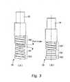
- Fig. 3illustrates a configuration of the coil spring 28 in the first embodiment in detail.
- Fig. 3(A)shows the coil spring 28 before being compressed, and
- Fig. 3(B)shows the coil spring 28 after being compressed.
- a grip portion 281 located in the middlehas a smaller coil diameter than that of an upper end 282 and a lower end 283.
- the grip portion 281has a larger pitch angle than that of the upper end 282 and the lower end 283.
- the grip portion 281has a coil inner diameter and a pitch angle different from those of the upper end 282 and the lower end 283.
- the coil spring 28has a nonlinear spring constant and an inconstant natural frequency. This can effectively prevent resonance of the coil spring 28 caused by a specific frequency. This allows the treatment tool to be firmly gripped, and achieves a high vibration absorbing property. This allows a skilled user to properly operate the handpiece, and provides high safety and durability.
- the grip portion 281has a larger pitch angle than that of the upper end 282 and the lower end 283.
- the pitch angle of the grip portion 281is preferably as large as possible. This can maximize the inner diameter of the grip portion 281.
- a winding direction of the coil spring 28 described aboveis set to a narrowing direction of the coil inner diameter during rotational driving. More specifically, in the handpiece in this embodiment, a left-handed coil spring 28 is used for a right-handed handpiece. This is particularly effective for an air turbine type handpiece with one rotational direction, thereby effectively increasing a gripping force of the treatment tool.
- predetermined pressureis applied to the coil spring 28 described above, and thus compression reduces the pitch angles of the upper end 282 and the lower end 283.
- the upper end 282 and the lower end 283tend to irregularly repeat contact and separation by the vibration. This can significantly change the natural frequency, and this vibration control prevents resonance and allows smooth treatment.
- the coil spring 28is used in which the grip portion 281 has an inner diameter different from that of the upper end 282 and the lower end 283, but the shape of the coil spring 28 is not limited to this.
- a conical coil springmay be used or a barrel-shaped coil spring having a coil inner diameter gradually increasing toward the middle may be used as a coil spring having an inconstant coil inner diameter for providing an inconstant natural frequency of the coil spring.
- the coil spring 28is used in which the grip portion 281 has a pitch angle different from that of the upper end 282 and the lower end 283, but the shape of the coil spring 28 is not limited to this. Specifically, a coil spring having a gradually changing pitch angle may be used or a coil spring having a pitch angle changing stepwise may be used as a coil spring having an inconstant pitch angle of the coil spring for providing an inconstant natural frequency of the coil spring.
- the grip portion 281 of the coil spring 28has about three turns, but the number of turns of the grip portion 281 is not limited to this. Specifically, the number of turns may be set that can ensure an amount of change of a predetermined coil inner diameter in relation to an effective span of the head portion 10.
- the push button 32is pressed to move the pressing member 30 in a compressing direction of the coil spring 28 to increase the inner diameter of the grip portion 281, but the method for increasing the inner diameter of the grip portion is not limited to this.
- a configuration of twisting the coil spring 28 in the direction opposite to the winding directionmay be provided. This can further increase the inner diameter of the grip portion 281.
- the treatment toolsis attached or detached using the change in inner diameter when the coil spring 28 is compressed.
- the grip portion 281has a large pitch angle to increase the amount of change in coil inner diameter to increase the gripping force.
- the coil spring 28is made of a highly elastic material, and has a drawback in coiling accuracy in terms of its property. This increases variations in coil inner diameter, which may cause variations in gripping performance of the treatment tool.
- Fig. 4illustrates a structure of a coil spring 28 used in a device for gripping a treatment tool of the second embodiment.
- Fig. 4in the coil spring 28, an inner diameter surface of a grip portion 281 is ground.
- Fig. 5shows an axially cut section of a part of the grip portion 281 of the coil spring 28 surrounded by a circle in Fig. 4.
- Fig. 5(A)shows the coil spring without a push button 32 being pressed
- Fig. 5(B)shows the coil spring with the push button 32 being pressed.
- a ground surface 284is formed by grinding a partial region of an inner diameter surface 285. More specifically, as shown in Fig. 5(B) , the ground surface 284 is formed by grinding the inner diameter surface 285 of the coil spring 28 to a predetermined inner diameter with the push button 32 being pressed, that is, the coil spring 28 being compressed.
- Such a coil spring 28facilitates accuracy control of the coil inner diameter.
- a highly elastic material for a coil springcauses wide variations in coil inner diameter in terms of its property.
- the coil inner diameteris ground to the predetermined coil inner diameter with the coil spring 28 being compressed, thereby effectively increasing accuracy of the coil inner diameter in insertion of the treatment tool, and further making the coil spring 28 more flexible.
- the device for gripping the treatment tool of this embodimentallows an outside of the inserted treatment tool to be firmly gripped by the edge 286.
- the edge 286 of the ground surface 284is retracted in the direction opposite to the center of the coil, thereby further increasing the coil inner diameter. This can effectively increase an amount of increase in coil inner diameter in attachment and detachment of the treatment tool as compared to a case of using the coil spring 28 without the ground surface 284.
Landscapes
- Health & Medical Sciences (AREA)
- Oral & Maxillofacial Surgery (AREA)
- Dentistry (AREA)
- Epidemiology (AREA)
- Life Sciences & Earth Sciences (AREA)
- Animal Behavior & Ethology (AREA)
- General Health & Medical Sciences (AREA)
- Public Health (AREA)
- Veterinary Medicine (AREA)
- Engineering & Computer Science (AREA)
- Mechanical Engineering (AREA)
- Dental Tools And Instruments Or Auxiliary Dental Instruments (AREA)
Description
- The present invention relates to a structure of a device for gripping a treatment tool of a handpiece used for medical or dental services.
- Various types of handpieces are used for medical or dental services, which, for example, rotate a treatment tool at high speed, reciprocate or vibrate the treatment tool depending on treatment purposes, treatment areas, or treatment methods. Also, various types of treatment tools are used. Such a treatment tool is removably attached by a gripping device (chuck) of a handpiece and can be easily changed. Thus, a chuck structure for gripping a treatment tool of a medical/dental handpiece requires performance of firmly gripping the treatment tool under any conditions, durability, and reliability. Also, a head portion of the handpiece needs to be as small as possible so as to facilitate treatment operation. Further, as performance essential to a medical/dental handpiece, chemical resistance, autoclave resistance, and corrosion resistance are considered.
- In this respect, for example,
JP-A-60-90609 - Patent Document 1:
JP-A-60-90609 - Patent Document 2:
JP-A-59-51846 - Patent Document 3:
JP-U-61-39520 US 3,967,831 discloses a spring coil holding device utilizing an integral torsion multistage spring coil placed in an actuating sleeve and a housing sleeve, the integral spring coil being actuated by a rotational mechanism (the actuating sleeve), the rotational mechanism being operable to rotate the upper coils of the spring in a direction opposite to the direction of the winding of the coil spring, thereby releasing a rod-shaped object. The torsion spring is restored to its original condition by its own resilience for clamp holding a rod-shaped object.WO 9817427 US 610,483 discloses a dental handpiece including a drill holder having a torsion spring and means for applying a rotational force to the torsion spring to enable the spring to grip the drill.- In the conventional chuck structure described above, various vibrations caused by various treatment tools are transferred to the twisting member in the form of a coil spring during treatment by a skilled user using the treatment tools. The coil spring as the twisting member has a constant natural frequency, and thus such vibrations may resonate and be amplified. In this case, a gripping force of the twisting member may be reduced to cause the treatment tool to slip or bounce during treatment to prevent intended treatment, and the treatment tool may be unsafely removed from the handpiece. This is a common problem of chuck structures using a cylindrical elastic span that is a main device for gripping a treatment tool of a handpiece, not limited to the chuck structure using the twisting member in the form of a coil spring.
- The present invention is achieved to solve the above problem, and has an object to provide a device for gripping a treatment tool of a handpiece that allows the treatment tool to be easily attached and detached to and from the handpiece, firmly grips the treatment tool, and achieves a high vibration absorbing property.
- In accomplishing the above object, according to a first aspect of the present invention, there is provided a device for gripping a treatment tool of a handpiece comprising: a spindle rotatably installed; and a coil spring that is set in the spindle and rotated integrally with the spindle, the treatment tool inserted from a tip of the spindle into the coil spring being gripped by an inner diameter surface of a grip portion of the coil spring, the device wherein: the coil spring has an inconstant natural frequency, and wherein the coil spring includes the grip portion in a partial region thereof, and the grip portion has a smaller inner diamter than that of other regions, and wherein the device further comprises a compression mechanism that includes the pressing member installed between a rear end of the spindle and the coil spring, the compression mechanism being operable to press the pressing member from the rear end of the spindle to axially compress the coil spring, and wherein the inner diameter of the coil spring is increased when the coil spring is compressed.
- According to a second aspect of the present invention, there is provided the device as described in the first aspect, wherein the coil spring includes the grip portion in a middle region thereof.
- According to a third aspect of the present invention, there is provided the device as described in the first or second aspects, wherein the coil spring has an inconstant pitch angle.
- According to a fourth aspect of the present invention, there is provided the device as described in any one of the first to third aspects,
wherein the handpiece is a medical or dental handpiece and wherein the inner diameter of the grip portion is smaller than an outer diameter of the treatment tool when the compression mechanism is not operated, and larger than the outer diameter of the treatment tool when the compression mechanism is operated. - According to a fifth aspect of the present invention, there is provided the device as described in the fourth aspect, wherein an inner diameter portion of the grip portion has a ground surface along a outer surface of the treatment tool when the compression mechanism is operated.
- According to a sixth aspect of the present invention, there is provided the device as described in the fourth or fifth aspect, wherein the coil spring includes the grip portion in a partial region thereof, and the grip portion has a larger pitch angle than that of other regions.
- In the first aspect of the present invention, the treatment tool is gripped by the coil spring having an inconstant natural frequency. Thus, according to the present invention, a situation in which the coil spring is subjected to specific vibration and resonates can be avoided, thereby achieving high vibration absorbing performance and stable gripping performance.
- The grip portion of the coil spring has a smaller coil inner diameter than that of other regions. Thus, according to the present invention, the grip portion can firmly grip the treatment tool. The coil spring has different coil inner diameters depending on regions. Thus, according to the present invention, a spring constant can be effectively made nonlinear to provide an inconstant natural frequency.
- In the second aspect of the present invention, the coil spring has an hourglass shape with a narrowed middle region. Thus, according to the present invention, a spring constant of the coil spring can be effectively made nonlinear to provide an inconstant natural frequency.
- In the third aspect of the present invention, a coil spring having an inconstant pitch angle is used. Thus, according to the present invention, a spring constant of the coil spring can be effectively made nonlinear to provide an inconstant natural frequency.
- When the coil spring is compressed, the inner diameter of the coil spring is increased. In the fourth aspect of the present invention, if the compression mechanism compresses the coil spring, the inner diameter of the grip portion temporality becomes larger than an outer diameter of the treatment tool. If the treatment tool is inserted into the coil spring in this state to release the compression, the inner diameter of the grip portion tries to become smaller than the outer diameter of the treatment tool to firmly fasten the treatment tool. Thus, according to the present invention, the treatment tool can be attached and detached with a simple configuration, and a firm gripping force can be obtained.
- In the fifth aspect of the present invention, an inner diameter portion of the grip portion has a ground surface along an outer surface of the treatment tool when the compression mechanism compresses the grip portion. Thus, according to the present invention, a larger difference in inner diameter between in compression and in normal time can be obtained than in a case without the ground surface, thereby allowing the treatment tool to be more firmly gripped. The treatment tool is fastened and gripped by an edge of the ground surface, thereby providing a further gripping force. The ground surface of the coil spring is formed along the outer surface of the treatment tool with the grip portion being compressed, and thus a product error of the inner diameter of the coil spring can be accepted.
- In the sixth aspect of the present invention, the grip portion has a larger pitch angle than that of other regions. Thus, according to the present invention, an amount of increase in inner diameter of the grip portion in compression of the spring can be effectively increased.
Fig. 1 is an illustration showing a section of a head portion of a medical/dental handpiece used in a first Embodiment.Fig. 2 is a sectional view showing apush button 32 being pressed in the medical/dental handpiece used in a first Embodiment of the present invention.Fig. 3 is an illustration showing a configuration of acoil spring 28 in a first Embodiment in detail.Fig. 4 is an illustration showing a structure of acoil spring 28 used in a device for gripping a treatment tool of a second Embodiment.Fig. 5 is an illustration showing an axially cut section of a part of agrip portion 281 of acoil spring 28 surrounded by a circle inFig. 4 .- Now, embodiments of the present invention will be described with reference to the drawings. In the drawings, the same components are denoted by the same reference numerals, and overlapping descriptions will be omitted. The embodiments below do not limit the invention.
Fig. 1 shows a section of a head portion of a medical/dental handpiece used in a first embodiment. The medical/dental handpiece in the first embodiment is configured as an air turbine type handpiece that is rotationally driven by supplied compressed air. As shown inFig. 1 , ahead portion 10 of the handpiece includes ahead housing 12. Thehead housing 12 is connected to a grip portion (not shown) of the handpiece, and compressed air is introduced into thehead housing 12 through the inside of the grip portion. A structure relating to introduction and discharge of compressed air is not an essential part of the present invention but is a known structure, and thus detailed descriptions thereof will be omitted.- The
head housing 12 houses acartridge 14. Thecartridge 14 can be easily attached or detached by removing ahead cap 16 threaded on thehead housing 12. An internal configuration of thecartridge 14 will be described in detail below. - The
cartridge 14 includes aspindle 18 for gripping the treatment tool. A plurality ofrotary vanes 20 for rotationally driving the spindle with compressed air are provided on the middle of an outer periphery of thespindle 18.Ball bearings spindle 18 in thecartridge 14 are provided in upper and lower positions of thespindle 18 with therotary vanes 20 therebetween. - In the
spindle 18, acoil spring 28 for gripping the treatment tool and a pressingmember 30 for axially compressing thecoil spring 28 are provided, and set in thespindle 18 in a pressed manner by a rear end setscrew 181. Thecoil spring 28 is made of a high-strength spring material for ensuring durability, autoclave resistance, chemical resistance, corrosion resistance, and safety required for a medical/dental handpiece. The pressingmember 30 includes a securingportion 301 provided at one end and secured to thecoil spring 28, and apressing portion 302 provided at the other end and protruding from the rear end setscrew 181 of thespindle 18. Aninsertion portion 303 into which the treatment tool is inserted is formed in the pressingmember 30 on the side of the securingportion 301. Thecoil spring 28 is installed between the pressingmember 30 and astep 182 in thespindle 18 with predetermined pressure being applied to thecoil spring 28. The shape of thecoil spring 28 will be described later in detail. - The
head cap 16 includes apush button 32 for pressing thepressing portion 302 of the pressingmember 30. Thepush button 32 is urged by aspring 34 in a direction opposite to a pressing direction of the pressingmember 30. - When the treatment tool is attached or detached to or from such a handpiece, the
push button 32 is pressed.Fig. 2 is a sectional view showing thepush button 32 being pressed in the medical/dental handpiece used in the first embodiment of the present invention. As shown inFig. 2 , when thepush button 32 is pressed, the pressingmember 30 is moved axially downward. This compresses thecoil spring 28 by a predetermined amount, thereby increasing an inner diameter of thecoil spring 28 by a predetermined amount. In the handpiece in this embodiment, the treatment tool is gripped using this characteristic. Specifically, a treatment tool grip portion of thecoil spring 28 has a smaller coil inner diameter than an outer diameter of the treatment tool before being compressed, and has a larger coil inner diameter than that after being compressed. Thus, according to such a treatment tool gripping structure, the treatment tool can be firmly gripped with a simple structure. - Next, with reference to
Fig. 3 , a characteristic configuration of this embodiment will be described in detail. As described above, the device for gripping the treatment tool of the handpiece of this embodiment has a structure in which the treatment tool is gripped by an inner diameter surface of thecoil spring 28. According to such a grip structure, the treatment tool can be firmly gripped using an effective span configured in a spiral shape in small space in thespindle 18. - However, various treatment tools are used with the medical/dental handpiece depending on treatment areas and forms of treatment. Thus, various vibrations are created in the treatment tool during treatment, and transferred to the
coil spring 28. If the vibrations resonate with natural vibration of thecoil spring 28, a sudden increase in amplitude may increase vibration or reduce a gripping force. - Thus, a coil spring having an inconstant natural frequency is used in the handpiece in this embodiment.
Fig. 3 illustrates a configuration of thecoil spring 28 in the first embodiment in detail.Fig. 3(A) shows thecoil spring 28 before being compressed, andFig. 3(B) shows thecoil spring 28 after being compressed. - As shown in
Fig. 3 , in thecoil spring 28, agrip portion 281 located in the middle has a smaller coil diameter than that of anupper end 282 and alower end 283. Thegrip portion 281 has a larger pitch angle than that of theupper end 282 and thelower end 283. - Using the
coil spring 28 having such a configuration provides the advantage described below. Specifically, in thecoil spring 28, thegrip portion 281 has a coil inner diameter and a pitch angle different from those of theupper end 282 and thelower end 283. Thus, thecoil spring 28 has a nonlinear spring constant and an inconstant natural frequency. This can effectively prevent resonance of thecoil spring 28 caused by a specific frequency. This allows the treatment tool to be firmly gripped, and achieves a high vibration absorbing property. This allows a skilled user to properly operate the handpiece, and provides high safety and durability. - In the
coil spring 28 described above, thegrip portion 281 has a larger pitch angle than that of theupper end 282 and thelower end 283. Thus, when thepush button 32 is pressed to compress thecoil spring 28, the inner diameter of thegrip portion 281 can be further increased. The pitch angle of thegrip portion 281 is preferably as large as possible. This can maximize the inner diameter of thegrip portion 281. - A winding direction of the
coil spring 28 described above is set to a narrowing direction of the coil inner diameter during rotational driving. More specifically, in the handpiece in this embodiment, a left-handed coil spring 28 is used for a right-handed handpiece. This is particularly effective for an air turbine type handpiece with one rotational direction, thereby effectively increasing a gripping force of the treatment tool. - Also, predetermined pressure is applied to the
coil spring 28 described above, and thus compression reduces the pitch angles of theupper end 282 and thelower end 283. Thus, when vibration input from the treatment tool during treatment is transferred to thecoil spring 28, theupper end 282 and thelower end 283 tend to irregularly repeat contact and separation by the vibration. This can significantly change the natural frequency, and this vibration control prevents resonance and allows smooth treatment. - In the first embodiment described above, the
coil spring 28 is used in which thegrip portion 281 has an inner diameter different from that of theupper end 282 and thelower end 283, but the shape of thecoil spring 28 is not limited to this. Specifically, for example, a conical coil spring may be used or a barrel-shaped coil spring having a coil inner diameter gradually increasing toward the middle may be used as a coil spring having an inconstant coil inner diameter for providing an inconstant natural frequency of the coil spring. - In the first embodiment described above, the
coil spring 28 is used in which thegrip portion 281 has a pitch angle different from that of theupper end 282 and thelower end 283, but the shape of thecoil spring 28 is not limited to this. Specifically, a coil spring having a gradually changing pitch angle may be used or a coil spring having a pitch angle changing stepwise may be used as a coil spring having an inconstant pitch angle of the coil spring for providing an inconstant natural frequency of the coil spring. - In the first embodiment described above, the
grip portion 281 of thecoil spring 28 has about three turns, but the number of turns of thegrip portion 281 is not limited to this. Specifically, the number of turns may be set that can ensure an amount of change of a predetermined coil inner diameter in relation to an effective span of thehead portion 10. - In the first embodiment described above, the
push button 32 is pressed to move the pressingmember 30 in a compressing direction of thecoil spring 28 to increase the inner diameter of thegrip portion 281, but the method for increasing the inner diameter of the grip portion is not limited to this. Specifically, in addition to compression of thecoil spring 28, a configuration of twisting thecoil spring 28 in the direction opposite to the winding direction may be provided. This can further increase the inner diameter of thegrip portion 281. - Next, with reference to
Fig. 4 or 5 , a second embodiment of the present invention will be described. For the device for gripping the treatment tool of the handpiece of the first embodiment described above, the treatment tools is attached or detached using the change in inner diameter when thecoil spring 28 is compressed. In the first embodiment described above, thegrip portion 281 has a large pitch angle to increase the amount of change in coil inner diameter to increase the gripping force. - However, the
coil spring 28 is made of a highly elastic material, and has a drawback in coiling accuracy in terms of its property. This increases variations in coil inner diameter, which may cause variations in gripping performance of the treatment tool. - In the second embodiment, the
coil spring 28 is further machined.Fig. 4 illustrates a structure of acoil spring 28 used in a device for gripping a treatment tool of the second embodiment. As shown inFig. 4 , in thecoil spring 28, an inner diameter surface of agrip portion 281 is ground.Fig. 5 shows an axially cut section of a part of thegrip portion 281 of thecoil spring 28 surrounded by a circle inFig. 4. Fig. 5(A) shows the coil spring without apush button 32 being pressed, andFig. 5(B) shows the coil spring with thepush button 32 being pressed. - As shown in
Fig. 5 , aground surface 284 is formed by grinding a partial region of aninner diameter surface 285. More specifically, as shown inFig. 5(B) , theground surface 284 is formed by grinding theinner diameter surface 285 of thecoil spring 28 to a predetermined inner diameter with thepush button 32 being pressed, that is, thecoil spring 28 being compressed. - Such a
coil spring 28 facilitates accuracy control of the coil inner diameter. Specifically, as described above, a highly elastic material for a coil spring causes wide variations in coil inner diameter in terms of its property. Thus, as thecoil spring 28 in this embodiment, the coil inner diameter is ground to the predetermined coil inner diameter with thecoil spring 28 being compressed, thereby effectively increasing accuracy of the coil inner diameter in insertion of the treatment tool, and further making thecoil spring 28 more flexible. - When the pressing of the
push button 32 is released and an amount of compression of thecoil spring 28 is changed, a wire of thecoil spring 28 is twisted. At this time, as shown inFig. 5(A) , anedge 286 of theground surface 284 is twisted and overhangs toward the center of the coil. Thus, the device for gripping the treatment tool of this embodiment allows an outside of the inserted treatment tool to be firmly gripped by theedge 286. - Further, in the state shown in
Fig. 5(B) , theedge 286 of theground surface 284 is retracted in the direction opposite to the center of the coil, thereby further increasing the coil inner diameter. This can effectively increase an amount of increase in coil inner diameter in attachment and detachment of the treatment tool as compared to a case of using thecoil spring 28 without theground surface 284. - 10 head portion
- 12 head housing
- 14 cartridge
- 16 head cap
- 18 spindle
- 181 rear end set screw
- 182 step
- 20 rotary vane
- 24,26 Ball bearings
- 28 coil spring
- 281 grip portion
- 282 upper end
- 283 lower end
- 284 ground surface
- 285 inner diameter surface
- 286 edge
- 30 pressing member
- 301 securing portion
- 302 pressing portion
- 303 insertion portion
- 32 push button
- 34 spring
Claims (6)
- A device for gripping a treatment tool of a handpiece, the device comprising: a rotatable spindle (18) and a coil spring (28) that is set in the spindle (18) and rotatable integrally with the spindle (18), the coil spring being compressed between a pressing member (30) and a step (182) in the spindle (18), the treatment tool insertable from a tip of the spindle (18) into the coil spring (28) being gripped by an inner diameter surface (285) of a grip portion (281) of the coil spring (28), wherein:the coil spring (28) has an inconstant natural frequency, andwherein the coil spring (28) includes the grip portion (281) in a partial region thereof, and the grip portion (281) has a smaller inner diameter than that of other regions (282, 283), andwherein the device further comprises a compression mechanism that includes the pressing member (30) installed between a rear end of the spindle (18) and the coil spring (28), the compression mechanism being operable to press the pressing member (30) from the rear end of the spindle (18) to axially compress the coil spring (28), andwherein the inner diameter of the coil spring is increased when the coil spring is compressed.
- The device for gripping a treatment tool of a handpiece according to claim 1, wherein the coil spring (28) includes the grip portion (281) in a middle region thereof.
- The device for gripping a treatment tool of a handpiece according to claim 1 or 2, wherein the coil spring (28) has an inconstant pitch angle.
- The device for gripping a treatment tool of a handpiece according to any one of claims 1 to 3,
wherein the handpiece is a medical or dental handpiece and wherein the inner diameter of the grip portion (281) is configured to be smaller than an outer diameter of the associated insertable treatment tool when the compression mechanism is not operated, and is configured to be larger than the outer diameter of the associated insertable treatment tool when the compression mechanism is operated. - The device for gripping a treatment tool of a handpiece according to claim 4, wherein an inner diameter portion (285) of the grip portion (281) has a ground surface (284) along an outer surface of the treatment tool when the compression mechanism is operated.
- The device for gripping a treatment tool of a handpiece according to claim 4 or 5, wherein the coil spring (28) includes the grip portion (281) in a partial region thereof, and the grip portion (281) has a larger pitch angle than that of other regions (282, 283).
Applications Claiming Priority (1)
| Application Number | Priority Date | Filing Date | Title |
|---|---|---|---|
| PCT/JP2009/068388WO2011052034A1 (en) | 2009-10-27 | 2009-10-27 | Therapeutic tool gripping device for a handpiece |
Publications (3)
| Publication Number | Publication Date |
|---|---|
| EP2494937A1 EP2494937A1 (en) | 2012-09-05 |
| EP2494937A4 EP2494937A4 (en) | 2013-06-26 |
| EP2494937B1true EP2494937B1 (en) | 2015-08-19 |
Family
ID=43921478
Family Applications (1)
| Application Number | Title | Priority Date | Filing Date |
|---|---|---|---|
| EP09850814.6ANot-in-forceEP2494937B1 (en) | 2009-10-27 | 2009-10-27 | Therapeutic tool gripping device for a handpiece |
Country Status (6)
| Country | Link |
|---|---|
| US (1) | US20120153580A1 (en) |
| EP (1) | EP2494937B1 (en) |
| JP (1) | JP5003847B2 (en) |
| KR (1) | KR101211281B1 (en) |
| CN (1) | CN102596090B (en) |
| WO (1) | WO2011052034A1 (en) |
Families Citing this family (12)
| Publication number | Priority date | Publication date | Assignee | Title |
|---|---|---|---|---|
| JP6047756B2 (en)* | 2012-10-12 | 2016-12-21 | 株式会社タニタ | Cigar springs, connectors, electrodes and electrometers |
| DE102013102204A1 (en)* | 2013-03-06 | 2014-09-11 | Hans-Jürgen Türk | Mounting device for detachable coupling of dental drill, has fixing element whose effective diameter is transferrable from condition into another condition, where free end region of drill is fixedly engaged with element in latter condition |
| CN107635472A (en) | 2015-06-19 | 2018-01-26 | 神经系统分析公司 | Transcranial doppler detector |
| CN105395260B (en)* | 2015-12-10 | 2018-07-24 | 佛山市德克医疗器械有限公司 | Package assembly and mandrel component for push type high speed dental turbo mobile phone |
| CN105411687B (en)* | 2015-12-10 | 2018-07-24 | 佛山市德克医疗器械有限公司 | A kind of push type high speed dental turbo mobile phone |
| US11589836B2 (en) | 2016-01-05 | 2023-02-28 | Novasignal Corp. | Systems and methods for detecting neurological conditions |
| WO2017120361A1 (en) | 2016-01-05 | 2017-07-13 | Neural Analytics, Inc. | Integrated probe structure |
| CN108778140A (en) | 2016-01-05 | 2018-11-09 | 神经系统分析公司 | Systems and methods for determining clinical indications |
| WO2017189623A1 (en)* | 2016-04-25 | 2017-11-02 | Neural Analytics, Inc. | Probe structure |
| JP7310551B2 (en)* | 2019-11-01 | 2023-07-19 | 株式会社ジェイテクト | Worm reducer and method for manufacturing worm reducer |
| KR102429250B1 (en) | 2019-12-23 | 2022-08-04 | (주)세신정밀 | Air-turbine handpiece for boldly grasping dental tool |
| KR102820932B1 (en)* | 2021-12-17 | 2025-06-16 | 가부시키가이샤 나카니시 | Dental handpiece |
Family Cites Families (25)
| Publication number | Priority date | Publication date | Assignee | Title |
|---|---|---|---|---|
| US414078A (en)* | 1889-10-29 | George rehfuss | ||
| US610483A (en)* | 1898-09-06 | Charles p | ||
| US959530A (en)* | 1904-11-30 | 1910-05-31 | Meier G Hilpert | Tool-retainer for air, electric, or mechanically-driven implements. |
| US1448987A (en)* | 1919-11-26 | 1923-03-20 | John D Spalding | Chuck |
| US1552085A (en)* | 1921-04-02 | 1925-09-01 | Grip Nut Co | Tool-holding chuck |
| US2105330A (en)* | 1935-01-10 | 1938-01-11 | Teletype Corp | Tool holder |
| GB583608A (en)* | 1945-03-06 | 1946-12-20 | John Leonard Young | Improvements relating to chucks |
| US2539610A (en)* | 1947-04-05 | 1951-01-30 | Western Electric Co | Chuck for use with rotary tools |
| FR961921A (en)* | 1947-11-14 | 1950-05-25 | ||
| US2564893A (en)* | 1948-05-10 | 1951-08-21 | Eugene V Gibbons | Quick-detachable chuck |
| US2570570A (en)* | 1949-08-22 | 1951-10-09 | Lee Foundation For Nutritional | Tool chuck |
| US2652270A (en)* | 1949-11-18 | 1953-09-15 | John A Jones | Coupling |
| US2818264A (en)* | 1956-01-09 | 1957-12-31 | Leslie W Overstreet | Gripping mechanism for use in expanding mandrels and contracting collets |
| US2936625A (en)* | 1957-05-08 | 1960-05-17 | George W Heiseler | Self-tightening gripping device |
| CH580421A5 (en)* | 1974-09-30 | 1976-10-15 | Mosimann David | |
| US3967831A (en)* | 1974-10-21 | 1976-07-06 | Chang Ming Chao | Spring coil holding device |
| EP0015659B1 (en)* | 1979-02-16 | 1983-05-11 | Syntex (U.S.A.) Inc. | Dental instrument or adapter therefor having a lamp assembly suspension including vibration and thermal isolation means |
| DE3145133A1 (en)* | 1980-12-22 | 1982-07-29 | Micro-Mega S.A., 25006 Besancon | DEVICE FOR FASTENING DENTAL DRILLING OR. MILLING TOOLS IN THE TOP OF TURBINES FOR DENTAL HANDPIECES |
| JPS6090609A (en) | 1983-10-24 | 1985-05-21 | Osada Denki Kogyo Kk | Spring chuck |
| US5826888A (en)* | 1996-10-24 | 1998-10-27 | Power Tool Holders Incorporated | Quick release chuck device |
| IL120813A (en)* | 1997-05-09 | 2001-06-14 | Cohen Yechiel | Clamping device particularly useful for dental handpieces |
| CN2691511Y (en)* | 2003-11-03 | 2005-04-13 | 郑平 | High speed air-turbo hand drill for dental use |
| US7214060B2 (en)* | 2004-02-17 | 2007-05-08 | Bien-Air Holding S.A. | Handpiece for dental or surgical use |
| JP4084818B2 (en)* | 2005-09-29 | 2008-04-30 | 株式会社ナカニシ | Dental handpiece |
| JP5298509B2 (en)* | 2007-11-19 | 2013-09-25 | オムロンヘルスケア株式会社 | electric toothbrush |
- 2009
- 2009-10-27EPEP09850814.6Apatent/EP2494937B1/ennot_activeNot-in-force
- 2009-10-27CNCN200980162171.1Apatent/CN102596090B/ennot_activeExpired - Fee Related
- 2009-10-27KRKR1020127009909Apatent/KR101211281B1/ennot_activeExpired - Fee Related
- 2009-10-27JPJP2011538135Apatent/JP5003847B2/ennot_activeExpired - Fee Related
- 2009-10-27WOPCT/JP2009/068388patent/WO2011052034A1/enactiveApplication Filing
- 2009-10-27USUS13/392,686patent/US20120153580A1/ennot_activeAbandoned
Also Published As
| Publication number | Publication date |
|---|---|
| WO2011052034A1 (en) | 2011-05-05 |
| KR101211281B1 (en) | 2012-12-11 |
| JPWO2011052034A1 (en) | 2013-03-14 |
| KR20120056875A (en) | 2012-06-04 |
| CN102596090A (en) | 2012-07-18 |
| US20120153580A1 (en) | 2012-06-21 |
| CN102596090B (en) | 2014-04-30 |
| JP5003847B2 (en) | 2012-08-15 |
| EP2494937A4 (en) | 2013-06-26 |
| EP2494937A1 (en) | 2012-09-05 |
Similar Documents
| Publication | Publication Date | Title |
|---|---|---|
| EP2494937B1 (en) | Therapeutic tool gripping device for a handpiece | |
| EP0776634B1 (en) | Wrenchless collet for surgical blade | |
| CN102202587B (en) | Medical/surgical powered handpiece for rotating an accessory shaft with a coupling assembly that facilitates fine or coarse adjustment of accessory shaft extension | |
| US8647116B2 (en) | Rotary endodontic file with frictional grip | |
| TW200942366A (en) | Torque sleeve | |
| US20080057468A1 (en) | Endodontic Instrument | |
| JP2003517350A (en) | Endodontic instruments and methods for crushing contaminants | |
| JP2008529821A (en) | Chuck for self-centering drill bit | |
| WO2014187318A1 (en) | Ultrasonic knife cutting head and ultrasonic knife | |
| US6913429B1 (en) | Tooless bit retaining assembly | |
| US20150071721A1 (en) | Arbor assembly for use with a cutting device, such as a cutter or hole saw | |
| KR101947671B1 (en) | Apparatus for twisting electric wire | |
| CN106901804B (en) | Ultrasonic knife transducer module and ultrasonic knife | |
| US20060149290A1 (en) | Cutting and forming device | |
| US20040064928A1 (en) | Piston pin spiral or wire lock ring insertion tool | |
| EP2098335B1 (en) | Improved magnetic socket structure | |
| KR101521279B1 (en) | Multitool | |
| AU2003300917B9 (en) | Ultrasonic dental handpiece having a rotatable head | |
| JP2004195642A (en) | Power installing tool of spiral coil insert | |
| US20170340373A1 (en) | Kirschner wire bending device | |
| US9136677B2 (en) | Flush cut tool | |
| US11918267B2 (en) | Medical pin removal tool | |
| KR102015350B1 (en) | Apparatus for twisting electric wire of replacing easily | |
| WO2004016393A1 (en) | Chamfering tool | |
| KR101033920B1 (en) | Dental screwdriver |
Legal Events
| Date | Code | Title | Description |
|---|---|---|---|
| PUAI | Public reference made under article 153(3) epc to a published international application that has entered the european phase | Free format text:ORIGINAL CODE: 0009012 | |
| 17P | Request for examination filed | Effective date:20120305 | |
| AK | Designated contracting states | Kind code of ref document:A1 Designated state(s):AT BE BG CH CY CZ DE DK EE ES FI FR GB GR HR HU IE IS IT LI LT LU LV MC MK MT NL NO PL PT RO SE SI SK SM TR | |
| DAX | Request for extension of the european patent (deleted) | ||
| A4 | Supplementary search report drawn up and despatched | Effective date:20130528 | |
| RIC1 | Information provided on ipc code assigned before grant | Ipc:A61C 1/14 20060101AFI20130522BHEP | |
| 17Q | First examination report despatched | Effective date:20140411 | |
| GRAP | Despatch of communication of intention to grant a patent | Free format text:ORIGINAL CODE: EPIDOSNIGR1 | |
| INTG | Intention to grant announced | Effective date:20150410 | |
| GRAS | Grant fee paid | Free format text:ORIGINAL CODE: EPIDOSNIGR3 | |
| GRAA | (expected) grant | Free format text:ORIGINAL CODE: 0009210 | |
| AK | Designated contracting states | Kind code of ref document:B1 Designated state(s):AT BE BG CH CY CZ DE DK EE ES FI FR GB GR HR HU IE IS IT LI LT LU LV MC MK MT NL NO PL PT RO SE SI SK SM TR | |
| REG | Reference to a national code | Ref country code:GB Ref legal event code:FG4D | |
| REG | Reference to a national code | Ref country code:DE Ref legal event code:R082 Ref document number:602009033099 Country of ref document:DE Representative=s name:HOFFMANN - EITLE PATENT- UND RECHTSANWAELTE PA, DE | |
| REG | Reference to a national code | Ref country code:CH Ref legal event code:EP | |
| REG | Reference to a national code | Ref country code:IE Ref legal event code:FG4D | |
| REG | Reference to a national code | Ref country code:AT Ref legal event code:REF Ref document number:743230 Country of ref document:AT Kind code of ref document:T Effective date:20150915 | |
| REG | Reference to a national code | Ref country code:DE Ref legal event code:R096 Ref document number:602009033099 Country of ref document:DE | |
| REG | Reference to a national code | Ref country code:FR Ref legal event code:PLFP Year of fee payment:7 | |
| REG | Reference to a national code | Ref country code:AT Ref legal event code:MK05 Ref document number:743230 Country of ref document:AT Kind code of ref document:T Effective date:20150819 | |
| REG | Reference to a national code | Ref country code:LT Ref legal event code:MG4D | |
| REG | Reference to a national code | Ref country code:NL Ref legal event code:MP Effective date:20150819 | |
| PG25 | Lapsed in a contracting state [announced via postgrant information from national office to epo] | Ref country code:LT Free format text:LAPSE BECAUSE OF FAILURE TO SUBMIT A TRANSLATION OF THE DESCRIPTION OR TO PAY THE FEE WITHIN THE PRESCRIBED TIME-LIMIT Effective date:20150819 Ref country code:FI Free format text:LAPSE BECAUSE OF FAILURE TO SUBMIT A TRANSLATION OF THE DESCRIPTION OR TO PAY THE FEE WITHIN THE PRESCRIBED TIME-LIMIT Effective date:20150819 Ref country code:GR Free format text:LAPSE BECAUSE OF FAILURE TO SUBMIT A TRANSLATION OF THE DESCRIPTION OR TO PAY THE FEE WITHIN THE PRESCRIBED TIME-LIMIT Effective date:20151120 Ref country code:NO Free format text:LAPSE BECAUSE OF FAILURE TO SUBMIT A TRANSLATION OF THE DESCRIPTION OR TO PAY THE FEE WITHIN THE PRESCRIBED TIME-LIMIT Effective date:20151119 Ref country code:LV Free format text:LAPSE BECAUSE OF FAILURE TO SUBMIT A TRANSLATION OF THE DESCRIPTION OR TO PAY THE FEE WITHIN THE PRESCRIBED TIME-LIMIT Effective date:20150819 | |
| PG25 | Lapsed in a contracting state [announced via postgrant information from national office to epo] | Ref country code:ES Free format text:LAPSE BECAUSE OF FAILURE TO SUBMIT A TRANSLATION OF THE DESCRIPTION OR TO PAY THE FEE WITHIN THE PRESCRIBED TIME-LIMIT Effective date:20150819 Ref country code:AT Free format text:LAPSE BECAUSE OF FAILURE TO SUBMIT A TRANSLATION OF THE DESCRIPTION OR TO PAY THE FEE WITHIN THE PRESCRIBED TIME-LIMIT Effective date:20150819 Ref country code:IS Free format text:LAPSE BECAUSE OF FAILURE TO SUBMIT A TRANSLATION OF THE DESCRIPTION OR TO PAY THE FEE WITHIN THE PRESCRIBED TIME-LIMIT Effective date:20151219 Ref country code:PT Free format text:LAPSE BECAUSE OF FAILURE TO SUBMIT A TRANSLATION OF THE DESCRIPTION OR TO PAY THE FEE WITHIN THE PRESCRIBED TIME-LIMIT Effective date:20151221 Ref country code:SE Free format text:LAPSE BECAUSE OF FAILURE TO SUBMIT A TRANSLATION OF THE DESCRIPTION OR TO PAY THE FEE WITHIN THE PRESCRIBED TIME-LIMIT Effective date:20150819 Ref country code:PL Free format text:LAPSE BECAUSE OF FAILURE TO SUBMIT A TRANSLATION OF THE DESCRIPTION OR TO PAY THE FEE WITHIN THE PRESCRIBED TIME-LIMIT Effective date:20150819 | |
| PG25 | Lapsed in a contracting state [announced via postgrant information from national office to epo] | Ref country code:NL Free format text:LAPSE BECAUSE OF FAILURE TO SUBMIT A TRANSLATION OF THE DESCRIPTION OR TO PAY THE FEE WITHIN THE PRESCRIBED TIME-LIMIT Effective date:20150819 | |
| PG25 | Lapsed in a contracting state [announced via postgrant information from national office to epo] | Ref country code:DK Free format text:LAPSE BECAUSE OF FAILURE TO SUBMIT A TRANSLATION OF THE DESCRIPTION OR TO PAY THE FEE WITHIN THE PRESCRIBED TIME-LIMIT Effective date:20150819 Ref country code:EE Free format text:LAPSE BECAUSE OF FAILURE TO SUBMIT A TRANSLATION OF THE DESCRIPTION OR TO PAY THE FEE WITHIN THE PRESCRIBED TIME-LIMIT Effective date:20150819 Ref country code:SK Free format text:LAPSE BECAUSE OF FAILURE TO SUBMIT A TRANSLATION OF THE DESCRIPTION OR TO PAY THE FEE WITHIN THE PRESCRIBED TIME-LIMIT Effective date:20150819 Ref country code:CZ Free format text:LAPSE BECAUSE OF FAILURE TO SUBMIT A TRANSLATION OF THE DESCRIPTION OR TO PAY THE FEE WITHIN THE PRESCRIBED TIME-LIMIT Effective date:20150819 | |
| REG | Reference to a national code | Ref country code:DE Ref legal event code:R097 Ref document number:602009033099 Country of ref document:DE | |
| PG25 | Lapsed in a contracting state [announced via postgrant information from national office to epo] | Ref country code:LU Free format text:LAPSE BECAUSE OF FAILURE TO SUBMIT A TRANSLATION OF THE DESCRIPTION OR TO PAY THE FEE WITHIN THE PRESCRIBED TIME-LIMIT Effective date:20151027 Ref country code:RO Free format text:LAPSE BECAUSE OF FAILURE TO SUBMIT A TRANSLATION OF THE DESCRIPTION OR TO PAY THE FEE WITHIN THE PRESCRIBED TIME-LIMIT Effective date:20150819 | |
| REG | Reference to a national code | Ref country code:CH Ref legal event code:PL | |
| PLBE | No opposition filed within time limit | Free format text:ORIGINAL CODE: 0009261 | |
| STAA | Information on the status of an ep patent application or granted ep patent | Free format text:STATUS: NO OPPOSITION FILED WITHIN TIME LIMIT | |
| PG25 | Lapsed in a contracting state [announced via postgrant information from national office to epo] | Ref country code:MC Free format text:LAPSE BECAUSE OF FAILURE TO SUBMIT A TRANSLATION OF THE DESCRIPTION OR TO PAY THE FEE WITHIN THE PRESCRIBED TIME-LIMIT Effective date:20150819 | |
| 26N | No opposition filed | Effective date:20160520 | |
| REG | Reference to a national code | Ref country code:IE Ref legal event code:MM4A | |
| PG25 | Lapsed in a contracting state [announced via postgrant information from national office to epo] | Ref country code:LI Free format text:LAPSE BECAUSE OF NON-PAYMENT OF DUE FEES Effective date:20151031 Ref country code:CH Free format text:LAPSE BECAUSE OF NON-PAYMENT OF DUE FEES Effective date:20151031 | |
| PG25 | Lapsed in a contracting state [announced via postgrant information from national office to epo] | Ref country code:SI Free format text:LAPSE BECAUSE OF FAILURE TO SUBMIT A TRANSLATION OF THE DESCRIPTION OR TO PAY THE FEE WITHIN THE PRESCRIBED TIME-LIMIT Effective date:20150819 | |
| REG | Reference to a national code | Ref country code:FR Ref legal event code:PLFP Year of fee payment:8 | |
| PG25 | Lapsed in a contracting state [announced via postgrant information from national office to epo] | Ref country code:IE Free format text:LAPSE BECAUSE OF NON-PAYMENT OF DUE FEES Effective date:20151027 | |
| PG25 | Lapsed in a contracting state [announced via postgrant information from national office to epo] | Ref country code:BE Free format text:LAPSE BECAUSE OF FAILURE TO SUBMIT A TRANSLATION OF THE DESCRIPTION OR TO PAY THE FEE WITHIN THE PRESCRIBED TIME-LIMIT Effective date:20150819 | |
| PG25 | Lapsed in a contracting state [announced via postgrant information from national office to epo] | Ref country code:HU Free format text:LAPSE BECAUSE OF FAILURE TO SUBMIT A TRANSLATION OF THE DESCRIPTION OR TO PAY THE FEE WITHIN THE PRESCRIBED TIME-LIMIT; INVALID AB INITIO Effective date:20091027 Ref country code:BG Free format text:LAPSE BECAUSE OF FAILURE TO SUBMIT A TRANSLATION OF THE DESCRIPTION OR TO PAY THE FEE WITHIN THE PRESCRIBED TIME-LIMIT Effective date:20150819 Ref country code:SM Free format text:LAPSE BECAUSE OF FAILURE TO SUBMIT A TRANSLATION OF THE DESCRIPTION OR TO PAY THE FEE WITHIN THE PRESCRIBED TIME-LIMIT Effective date:20150819 | |
| PG25 | Lapsed in a contracting state [announced via postgrant information from national office to epo] | Ref country code:CY Free format text:LAPSE BECAUSE OF FAILURE TO SUBMIT A TRANSLATION OF THE DESCRIPTION OR TO PAY THE FEE WITHIN THE PRESCRIBED TIME-LIMIT Effective date:20150819 | |
| PG25 | Lapsed in a contracting state [announced via postgrant information from national office to epo] | Ref country code:HR Free format text:LAPSE BECAUSE OF FAILURE TO SUBMIT A TRANSLATION OF THE DESCRIPTION OR TO PAY THE FEE WITHIN THE PRESCRIBED TIME-LIMIT Effective date:20150819 | |
| PG25 | Lapsed in a contracting state [announced via postgrant information from national office to epo] | Ref country code:TR Free format text:LAPSE BECAUSE OF FAILURE TO SUBMIT A TRANSLATION OF THE DESCRIPTION OR TO PAY THE FEE WITHIN THE PRESCRIBED TIME-LIMIT Effective date:20150819 Ref country code:MT Free format text:LAPSE BECAUSE OF FAILURE TO SUBMIT A TRANSLATION OF THE DESCRIPTION OR TO PAY THE FEE WITHIN THE PRESCRIBED TIME-LIMIT Effective date:20150819 | |
| REG | Reference to a national code | Ref country code:FR Ref legal event code:PLFP Year of fee payment:9 | |
| PG25 | Lapsed in a contracting state [announced via postgrant information from national office to epo] | Ref country code:MK Free format text:LAPSE BECAUSE OF FAILURE TO SUBMIT A TRANSLATION OF THE DESCRIPTION OR TO PAY THE FEE WITHIN THE PRESCRIBED TIME-LIMIT Effective date:20150819 | |
| REG | Reference to a national code | Ref country code:FR Ref legal event code:PLFP Year of fee payment:10 | |
| PGFP | Annual fee paid to national office [announced via postgrant information from national office to epo] | Ref country code:IT Payment date:20201028 Year of fee payment:12 Ref country code:FR Payment date:20201020 Year of fee payment:12 Ref country code:GB Payment date:20201009 Year of fee payment:12 Ref country code:DE Payment date:20201020 Year of fee payment:12 | |
| REG | Reference to a national code | Ref country code:DE Ref legal event code:R119 Ref document number:602009033099 Country of ref document:DE | |
| GBPC | Gb: european patent ceased through non-payment of renewal fee | Effective date:20211027 | |
| PG25 | Lapsed in a contracting state [announced via postgrant information from national office to epo] | Ref country code:GB Free format text:LAPSE BECAUSE OF NON-PAYMENT OF DUE FEES Effective date:20211027 Ref country code:DE Free format text:LAPSE BECAUSE OF NON-PAYMENT OF DUE FEES Effective date:20220503 | |
| PG25 | Lapsed in a contracting state [announced via postgrant information from national office to epo] | Ref country code:FR Free format text:LAPSE BECAUSE OF NON-PAYMENT OF DUE FEES Effective date:20211031 | |
| PG25 | Lapsed in a contracting state [announced via postgrant information from national office to epo] | Ref country code:IT Free format text:LAPSE BECAUSE OF NON-PAYMENT OF DUE FEES Effective date:20211027 |