EP2494913B1 - Anorectal surgical instrument and anal dilator - Google Patents
Anorectal surgical instrument and anal dilatorDownload PDFInfo
- Publication number
- EP2494913B1 EP2494913B1EP10826068.8AEP10826068AEP2494913B1EP 2494913 B1EP2494913 B1EP 2494913B1EP 10826068 AEP10826068 AEP 10826068AEP 2494913 B1EP2494913 B1EP 2494913B1
- Authority
- EP
- European Patent Office
- Prior art keywords
- anal dilator
- cylindrical body
- stapler
- staple cartridge
- light source
- Prior art date
- Legal status (The legal status is an assumption and is not a legal conclusion. Google has not performed a legal analysis and makes no representation as to the accuracy of the status listed.)
- Active
Links
- 208000014617hemorrhoidDiseases0.000claimsdescription48
- 239000012780transparent materialSubstances0.000claimsdescription8
- 230000007423decreaseEffects0.000claims1
- 210000001519tissueAnatomy0.000description18
- 239000013307optical fiberSubstances0.000description15
- 230000000007visual effectEffects0.000description13
- 238000000034methodMethods0.000description5
- 210000004877mucosaAnatomy0.000description5
- 208000015815Rectal diseaseDiseases0.000description3
- 210000000436anusAnatomy0.000description3
- 238000004519manufacturing processMethods0.000description3
- 230000002792vascularEffects0.000description3
- 208000012287ProlapseDiseases0.000description2
- 210000002255anal canalAnatomy0.000description2
- 239000000835fiberSubstances0.000description2
- 238000005286illuminationMethods0.000description2
- 238000012986modificationMethods0.000description2
- 230000004048modificationEffects0.000description2
- 239000004033plasticSubstances0.000description2
- 238000001356surgical procedureMethods0.000description2
- 210000004876tela submucosaAnatomy0.000description2
- 230000001225therapeutic effectEffects0.000description2
- 206010010774ConstipationDiseases0.000description1
- 206010012735DiarrhoeaDiseases0.000description1
- 208000032843HemorrhageDiseases0.000description1
- 206010020880HypertrophyDiseases0.000description1
- 206010021639IncontinenceDiseases0.000description1
- 208000031481Pathologic ConstrictionDiseases0.000description1
- 206010065813Vaginal fistulaDiseases0.000description1
- 230000002411adverseEffects0.000description1
- 230000036770blood supplyEffects0.000description1
- 238000005520cutting processMethods0.000description1
- 230000001419dependent effectEffects0.000description1
- 238000003745diagnosisMethods0.000description1
- 201000010099diseaseDiseases0.000description1
- 208000037265diseases, disorders, signs and symptomsDiseases0.000description1
- 230000000694effectsEffects0.000description1
- 230000002349favourable effectEffects0.000description1
- 230000000968intestinal effectEffects0.000description1
- 238000004020luminiscence typeMethods0.000description1
- 239000000463materialSubstances0.000description1
- 239000012528membraneSubstances0.000description1
- 210000003205muscleAnatomy0.000description1
- 230000001575pathological effectEffects0.000description1
- 230000002980postoperative effectEffects0.000description1
- 238000003825pressingMethods0.000description1
- 210000000664rectumAnatomy0.000description1
- 239000007787solidSubstances0.000description1
- 208000037804stenosisDiseases0.000description1
- 230000036262stenosisEffects0.000description1
- 208000024891symptomDiseases0.000description1
- 210000001215vaginaAnatomy0.000description1
- 238000004804windingMethods0.000description1
Images


Classifications
- A—HUMAN NECESSITIES
- A61—MEDICAL OR VETERINARY SCIENCE; HYGIENE
- A61B—DIAGNOSIS; SURGERY; IDENTIFICATION
- A61B1/00—Instruments for performing medical examinations of the interior of cavities or tubes of the body by visual or photographical inspection, e.g. endoscopes; Illuminating arrangements therefor
- A61B1/32—Devices for opening or enlarging the visual field, e.g. of a tube of the body
- A—HUMAN NECESSITIES
- A61—MEDICAL OR VETERINARY SCIENCE; HYGIENE
- A61B—DIAGNOSIS; SURGERY; IDENTIFICATION
- A61B1/00—Instruments for performing medical examinations of the interior of cavities or tubes of the body by visual or photographical inspection, e.g. endoscopes; Illuminating arrangements therefor
- A61B1/06—Instruments for performing medical examinations of the interior of cavities or tubes of the body by visual or photographical inspection, e.g. endoscopes; Illuminating arrangements therefor with illuminating arrangements
- A61B1/0661—Endoscope light sources
- A61B1/0669—Endoscope light sources at proximal end of an endoscope
- A—HUMAN NECESSITIES
- A61—MEDICAL OR VETERINARY SCIENCE; HYGIENE
- A61B—DIAGNOSIS; SURGERY; IDENTIFICATION
- A61B17/00—Surgical instruments, devices or methods
- A61B17/02—Surgical instruments, devices or methods for holding wounds open, e.g. retractors; Tractors
- A61B17/0293—Surgical instruments, devices or methods for holding wounds open, e.g. retractors; Tractors with ring member to support retractor elements
- A—HUMAN NECESSITIES
- A61—MEDICAL OR VETERINARY SCIENCE; HYGIENE
- A61B—DIAGNOSIS; SURGERY; IDENTIFICATION
- A61B90/00—Instruments, implements or accessories specially adapted for surgery or diagnosis and not covered by any of the groups A61B1/00 - A61B50/00, e.g. for luxation treatment or for protecting wound edges
- A61B90/30—Devices for illuminating a surgical field, the devices having an interrelation with other surgical devices or with a surgical procedure
- A—HUMAN NECESSITIES
- A61—MEDICAL OR VETERINARY SCIENCE; HYGIENE
- A61M—DEVICES FOR INTRODUCING MEDIA INTO, OR ONTO, THE BODY; DEVICES FOR TRANSDUCING BODY MEDIA OR FOR TAKING MEDIA FROM THE BODY; DEVICES FOR PRODUCING OR ENDING SLEEP OR STUPOR
- A61M29/00—Dilators with or without means for introducing media, e.g. remedies
- A—HUMAN NECESSITIES
- A61—MEDICAL OR VETERINARY SCIENCE; HYGIENE
- A61B—DIAGNOSIS; SURGERY; IDENTIFICATION
- A61B1/00—Instruments for performing medical examinations of the interior of cavities or tubes of the body by visual or photographical inspection, e.g. endoscopes; Illuminating arrangements therefor
- A61B1/31—Instruments for performing medical examinations of the interior of cavities or tubes of the body by visual or photographical inspection, e.g. endoscopes; Illuminating arrangements therefor for the rectum, e.g. proctoscopes, sigmoidoscopes, colonoscopes
- A—HUMAN NECESSITIES
- A61—MEDICAL OR VETERINARY SCIENCE; HYGIENE
- A61B—DIAGNOSIS; SURGERY; IDENTIFICATION
- A61B17/00—Surgical instruments, devices or methods
- A61B2017/00831—Material properties
- A61B2017/00902—Material properties transparent or translucent
- A—HUMAN NECESSITIES
- A61—MEDICAL OR VETERINARY SCIENCE; HYGIENE
- A61M—DEVICES FOR INTRODUCING MEDIA INTO, OR ONTO, THE BODY; DEVICES FOR TRANSDUCING BODY MEDIA OR FOR TAKING MEDIA FROM THE BODY; DEVICES FOR PRODUCING OR ENDING SLEEP OR STUPOR
- A61M2210/00—Anatomical parts of the body
- A61M2210/10—Trunk
- A61M2210/1042—Alimentary tract
- A61M2210/1067—Anus
Definitions
- the present applicationrelates to the technical field of medical instruments, in particular, to a surgical instrument used in surgical operations for treating anorectal diseases.
- the present applicationfurther relates to an anal dilator in the surgical instrument.
- the hemorrhoidis one of the common diseases. As the saying goes, nine of ten men may suffer from hemorrhoids. The incidence of hemorrhoids is high, and is about 85% of all anorectal diseases. To explain causes of hemorrhoids, the theory of "anal canal vascular cushion", referred to as “anal cushion theory” for short, has been developed since 1960. In the theory, it is considered that the anal cushion is an annular tissue band having a width from 1.5cm to 2.0cm above the dentate line in the anal canal of the human body. The tissue band is thick and soft, is a highly specified vascular cushion, and is a normal tissue in the human body. However, the vascular cushion may become pathologic hypertrophy due to diarrhea, constipation, increased intra-abdominal pressure and so on, and then move down, thereby resulting in the hemorrhoid.
- the surgical operationis to cut out the mucosa and submucosa located at the level from 2 to 4 cm above the dentate line, such that the anal cushion is moved upwardly and is hung, thereby significantly alleviating the prolapse symptom.
- hemorrhoid bodyis atrophied after the surgical operation, since blood supply of arterial branches in the rectum to the hemorrhoid region is cut off by cutting out the tissues under the mucosal.
- the surgical operationis favorable all over the word due to some advantages, for example, painless after the surgical operation, simple in the surgical operation, and no anal incontinence.
- medical instruments used in the PPH operationinclude a hemorrhoid stapler, and fittings such as an anal dilator and a threading device, which must be used simultaneously as a complete set.
- anal dilatoris a necessary instrument in the surgical operation.
- the visual field at the anusis not good, it is inconvenient, even unsafe, to use the existing anal dilator. It can be seen that, the visual field of the surgical operation is illuminated by the anal dilator which has a diameter of about 4 cm and a depth above 8 cm in all the procedures, thus the visual field is considerably unclear. The surgeon sometimes needs an additional headlight to illuminate the surgical visual field, but sometimes, the visual field is still unclear.
- An object of the present applicationis to provide an anal dilator which is made of transparent materials and is provided with a luminescent light source.
- an operative fieldespecially a deep visual field, can be entirely illuminated for surgeons by the luminescent light source on the anal dilator, so as to greatly enhance convenience and safety of the surgical operation.
- Another object of the present applicationis to provide an anorectal surgical instrument provided with the anal dilator.
- the anal dilator according to the present applicationis further improved on the basis of the prior art.
- the external light source assemblyis provided at the enlarged edge of the anal dilator according to the present application.
- the luminescent light source of the external light source assemblycan emit a visible light with sufficient intensity. Since the cylindrical body is made of transparent materials, the visible light can illuminate the entire operative field, in particular, the deep visual field, through the wall or the light channel of the cylindrical body, which seems as if the cylindrical body had the luminescence function, thereby ensuring the safety and success of the surgical operation.
- the light source assemblyis arranged outside the cylindrical body, it facilitates operating and controlling without negative influence on application effects of the anal dilator.
- the disposable hemorrhoid stapler for the anorectal surgical instrumenthas a transparent staple cartridge, so as to allow an operator to clearly observe the range that a tissue to be resected enters an opening of the hemorrhoid stapler and a status that the tissue is lifted, and to determine whether a tissue that should not enter has been avoided, so as to ensure the excision range is accurate and complete and to increase the success rate of the surgical operation.
- FIGS. 1 to 410. anal dilator 10-1. cylindrical body 10-2. enlarged edge 20. light source assembly 30. optical fiber 40. light source interface
- FIG. 5100. cylindrical body 101. light channel 121. light emitting opening 200. enlarged edge 201. wedge-shaped hole 211. aperture 300. external light source assembly 301. light-concentrating head 302. battery 303. power switch 311. slope convex block 321. light incident opening
- figure 1is an outline view of a first example of an anal dilator
- figure 2is a structural view of the anal dilator shown in figure 1 .
- the anal dilator 10includes a transparent cylindrical body 10-1, with the cylindrical body 10-1 being provided on its top portion with an elastic enlarged edge 10-2.
- An outer contour of the whole anal dilator 10is of an inverted hat shape, with the cylindrical body 10-1 corresponding to a hat body and the trumpet-shaped enlarged edge 10-2 corresponding to a hat edge.
- the cylindrical body 10-1is marked with legible scales to facilitate observation and surgical operation of the surgeon.
- the trumpet-shaped enlarged edge 10-2is uniformly provided with several hollow-out portions.
- a light source assembly 20is arranged outside the enlarged edge 10-2.
- An optical fiber 30is wound circumferentially around an outer wall of the cylindrical body 10-1 and is connected to the light source assembly 20 via a light source interface 40 on the enlarged edge 10-2.
- the optical fiber 30employs a luminescent plastic fiber having a diameter from 0.25 mm to 0.5 mm.
- the light source assembly 20mainly includes a housing, and a luminescent light source and a battery which are located in the housing.
- the luminescent light sourceemploys a cold light source, for example, a high-brightness light emitting diode with a size of 2 ⁇ 2, 2 ⁇ 3, 2 ⁇ 4 and 2 ⁇ 5 mm, and a diameter ranged from 3 mm to 5 mm.
- the batterymay employ a button cell having a working voltage from 1.5 V to 5 V.
- figure 3is an outline view of a second example of an anal dilator
- figure 4is a structural view of the anal dilator shown in figure 3 .
- the anal dilator 10includes a transparent cylindrical body 10-1, with the cylindrical body 10-1 being provided on its top portion with an elastic enlarged edge 10-2.
- An outer contour of the whole anal dilator 10is of an inverted hat shape, with the cylindrical body 10-1 corresponding to a hat body and the trumpet-shaped enlarged edge 10-2 corresponding to a hat edge.
- the cylindrical body 10-1is marked with legible scales to facilitate observation and surgical operation of the surgeon.
- the trumpet-shaped enlarged edge 10-2is made of medical rubber material and is uniformly provided with several hollow-out portions.
- a light source assembly 20is arranged outside the enlarged edge 10-2.
- An optical fiber 30is arranged, in a longitudinal direction of the cylindrical body 10-1, on the outer wall of the cylindrical body 10-1 and is connected to the light source assembly 20 via a light source interface 40 on the enlarged edge 10-2.
- the optical fiber 30employs a luminescent plastic fiber having a diameter from 0.25 mm to 0.5 mm.
- the light source assembly 20mainly includes a housing, and a luminescent light source and a battery which are located in the housing.
- the luminescent light sourceemploys a cold light source, for example, a high-brightness light emitting diode with a size of 2 ⁇ 2, 2 ⁇ 3, 2 ⁇ 4 and 2 ⁇ 5 mm, and a diameter ranged from 3 mm to 5 mm.
- the batterymay employ a button cell having a working voltage from 1.5 V to 5 V.
- the optical fiber 30employs a side-glowing optical fiber. More preferably, the optical fiber 30 may be formed into a single strand or a mesh shape.
- the mesh-shaped optical fiberis composed of side-glowing optical fibers having small diameters, which may form a flexible light band.
- the above optical fibermay be located on an outer wall or an inner wall of the cylindrical body, or may be located between the outer wall and the inner wall of the cylindrical body.
- the optical fibermay be wound circumferentially around the inner wall of the cylindrical body, or may be arranged, in the longitudinal direction of the cylindrical body, on the inner wall of the cylindrical body.
- fine groovesmay be provided in the inner wall or the outer wall of the cylindrical body, or may be provided between the inner wall and the outer wall of the cylindrical body, such that the optical fiber can be embedded in the fine grooves.
- figure 5is an outline view an embodiment of the anal dilator according to the present application
- figure 6is a structural schematic view of an external light source assembly shown in figure 5
- figure 7is a sectional view of the cylindrical body shown in figure 5
- figure 8is a partial enlarged schematic view of part I in figure 7
- figure 9is a structural schematic view of the anal dilator shown in figure 5 , with the external light source assembly being removed.
- the anal dilatorincludes a transparent cylindrical body 100, with the cylindrical body 100 being provided on its top portion with an elastic enlarged edge 200.
- the enlarged edge 200is provided with two lateral wings, one of which is provided with a wedge-shaped hole 201.
- the cylindrical body 100 and the enlarged edge 200are both made of transparent materials, and are formed into a double-layer structure inside which a gap is formed.
- the gap inside the double-layer structureforms a light channel.
- a wedge-shaped light-concentrating head 301is provided at a front end of a luminescent light source of an external light source assembly 300.
- a slope convex block 311is provided on a top surface of the light-concentrating head 301 and is adjacent to a root portion of light-concentrating head 301, while a corresponding aperture 211 is provided in a top wall of the wedge-shaped hole 201.
- the light-concentrating head 301is inserted into the wedge-shaped hole 201 of the enlarged edge 200.
- the slope convex block 311can be elastically embedded into the aperture 211 when the light-concentrating head 301 is fitted into the wedge-shaped hole 201 in position, such that the external light source assembly 300 can be fixedly connected to the enlarged edge 200.
- the external light source assembly 300mainly includes the light-concentrating head 301, a light emitting diode (not shown in the figures), a battery 302 and a power switch 303.
- Two electrodes of the light emitting diodeare connected to a positive electrode and a negative electrode of the battery 302 via electric wires, respectively, and the light emitting diode protrudes out of a rectangular housing and into the light-concentrating head 301.
- the battery 302employs a button cell having a working voltage from 1.5V to 5V.
- the battery, together with the power switch 303,is mounted in the rectangular housing, with an operating end of the power switch 303 protruding out of the housing.
- a visible light from the light emitting diodepasses through a light incident opening 321 of a front end of the light-concentrating head 301 into a light channel 101 of the cylindrical body 100, such that an inner portion of the transparent cylindrical body is filled with light rays.
- the light rays of the visible lightform light paths within the cylindrical body, and illuminate the entire operative field after transmitting through and being continuously reflected (in the figures, the arrows indicate directions of the light rays, and the dotted lines indicate reflective paths of the light rays) by the inner wall of the cylindrical body.
- a contracted light emitting opening 121is provided at a bottom end of the cylindrical body 100, and the light rays transmit through the light emitting opening 121 to illuminate a deep visual field during the surgical operation.
- the wall of the cylindrical bodyalso may be a transparent solid body that can guide light and transmit light, and the operative field may be illuminated by the external light source assembly through the wall of the cylindrical body.
- the other structuresare substantially the same with the embodiment mentioned above and will not be described repeatedly.
- This cylindrical body with the structurehas a lower requirement of processing, which facilitates saving the manufacture cost and increasing the production efficiency.
- an anorectal surgical instrumentwhich includes a disposable hemorrhoid stapler and fittings such as the anal dilator and a thread-hooking device.
- a disposable hemorrhoid staplerand fittings such as the anal dilator and a thread-hooking device.
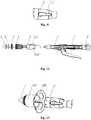
- figure 10is an outline view of a disposable hemorrhoid stapler according to the present application
- figure 11is a partial enlarged schematic view of a staple cartridge sleeve in figure 10
- figures 12is an exploded schematic view of an internal structure of the stapler shown in figure 10 .
- the disposable hemorrhoid staplerincludes an anvil assembly, a staple cartridge assembly and a gun body assembly.
- the anvil assemblyis located in the front of the hemorrhoid stapler and is connected to the gun body assembly via a connecting rod passing through the staple cartridge assembly.
- the anvil assemblyincludes a cone-shaped anvil 1.
- a circular grooveis provided in the anvil 1 to receive a cutter gasket ring 2.
- the staple cartridge assemblyincludes a staple cartridge 3, a staple-pushing piece 4 located behind the staple cartridge 3, and a staple cartridge sleeve 5.
- the staple cartridge 3 and the staple-pushing piece 4are mounted inside the staple cartridge sleeve 5.
- the staple cartridge sleeve 5is provided with a thread-hooking hole 5-2 through which a purse string can be pulled out and a purse-string sutured hemorrhoid tissue can be pulled into a cavity of the staple cartridge assembly.
- the staple cartridge assemblyincludes an annular cutter (not shown). The annular cutter is mounted in the staple-pushing piece 4, and can move together with the staple-pushing piece 4.
- the gun body assembly 6is located at a middle portion of the hemorrhoid stapler.
- a movable handle 7is provided below the gun body assembly 6, and an adjusting nut 8 is provided at the tail of the hemorrhoid stapler.
- the anvil 1can be driven to be adjacent to or away from the staple cartridge assembly by rotating the adjusting nut 8.
- the staple cartridge 3, the staple-pushing piece 4 and the staple cartridge sleeve 5are all made of transparent materials, such that it is possible for a surgeon to clearly observe whether there are lost staples in the staple cartridge, and to clearly observe the quantity and uniformity degree of the hemorrhoid tissue entering into the cavity of the staple cartridge assembly during a surgical operation.
- a pair of enlarged operating holes 5-1is provided in an outer sleeve body of the staple cartridge sleeve 5.
- a surgical clampmay be operated at the operating holes 5-1. It is possible to further observe the quantity of the hemorrhoid tissue entering into the cavity of the hemorrhoid stapler through the operating holes 5-1, and to adjust, by the surgical clamp, the hemorrhoid tissue to be uniform, such that the surgical operation is safer and more reliable, thereby avoiding corresponding complication.
- figure 13is a schematic view of the assembly of the disposable hemorrhoid stapler and the anal dilator according to the present application.
- the external light source assemblyis specially omitted in figure 13 in order to clearly show the fitting relationship between the disposable hemorrhoid stapler and the anal dilator.
- the surgeonuses three non-invasive forceps to perform fixing and outspreading operation at three points of the anus where fewer hemorrhoidal masses are prolapsed and extroversion of the anal membrane is slight.
- the anal dilatoris sleeved on a suturing device which in turn is sleeved on an anorectal introducer, such that the anal dilator and the suturing device can be guided into an anorectum together with the anorectal introducer.
- a prolapsed mucosamay fall in a semicircular tubular opening of the suturing device.
- the suturing devicemay be rotated such that the opening of the suturing device is aligned with the hemorrhoid tissue, and a circle of purse-string suture is performed at a position more than 3 centimeters to 4 centimeters above the dentate line, and only passes through the mucosa and the submucosa.
- the circular hemorrhoid stapleris rotated to be open to a maximum position and is guided in through the anal dilator, such that the anvil of the hemorrhoid stapler goes deep to reach the upper end of the purse-string suture, and then the purse-string suture is knotted and tightly tied to a central rod of the stapler.
- a tail end of the purse-string sutureis pulled out through the thread-hooking hole of the hemorrhoid stapler by a thread-hooking device, and the tail end of the suture pulled out of the stapler is knotted or is fixed by forceps.
- the adjusting nut at the tail end of the stapleris rotated such that the anvil is adjacent to the staple cartridge assembly, and at the same time, the suture is pulled properly such that the prolapsed mucosa layer is entirely placed in the cavity of the staple cartridge assembly of the hemorrhoid stapler.
- the hemorrhoid tissue in the cavitycan be adjusted with the surgical clamp to ensure the uniformity of the hemorrhoid tissue in the cavity.
- the stapleris completely closed, check whether the hemorrhoid tissue is appropriate or not.
- the movable handleis pressed to actuate and simultaneously resects the prolapsed mucosa in the cavity, and the stapler exits finally.
- the anal dilatoris provided with an external light source assembly, and the cylindrical body of the anal dilator is made of transparent materials.
- the staple cartridge, the staple-pushing piece and the staple cartridge sleeve of the hemorrhoid staplerare also made of transparent materials.
- a head portion of the hemorrhoid staplercan be inserted deep inside of the cylindrical body of the anal dilator, and when the power switch on the anal dilator is pressed to switch on the illumination device, rays of the visible light not only can illuminate the entire operative field, but also can transmit through the staple cartridge sleeve to illuminate the staple cartridge and the staple-pushing piece inside the staple cartridge sleeve.
Landscapes
- Health & Medical Sciences (AREA)
- Life Sciences & Earth Sciences (AREA)
- Surgery (AREA)
- Veterinary Medicine (AREA)
- Public Health (AREA)
- General Health & Medical Sciences (AREA)
- Engineering & Computer Science (AREA)
- Biomedical Technology (AREA)
- Heart & Thoracic Surgery (AREA)
- Animal Behavior & Ethology (AREA)
- Molecular Biology (AREA)
- Medical Informatics (AREA)
- Nuclear Medicine, Radiotherapy & Molecular Imaging (AREA)
- Pathology (AREA)
- Physics & Mathematics (AREA)
- Biophysics (AREA)
- Optics & Photonics (AREA)
- Radiology & Medical Imaging (AREA)
- Oral & Maxillofacial Surgery (AREA)
- Anesthesiology (AREA)
- Hematology (AREA)
- Surgical Instruments (AREA)
Description
- The present application relates to the technical field of medical instruments, in particular, to a surgical instrument used in surgical operations for treating anorectal diseases. The present application further relates to an anal dilator in the surgical instrument.
- The hemorrhoid is one of the common diseases. As the saying goes, nine of ten men may suffer from hemorrhoids. The incidence of hemorrhoids is high, and is about 85% of all anorectal diseases. To explain causes of hemorrhoids, the theory of "anal canal vascular cushion", referred to as "anal cushion theory" for short, has been developed since 1960. In the theory, it is considered that the anal cushion is an annular tissue band having a width from 1.5cm to 2.0cm above the dentate line in the anal canal of the human body. The tissue band is thick and soft, is a highly specified vascular cushion, and is a normal tissue in the human body. However, the vascular cushion may become pathologic hypertrophy due to diarrhea, constipation, increased intra-abdominal pressure and so on, and then move down, thereby resulting in the hemorrhoid.
- Therapeutic means for hemorrhoids has been changed greatly as the above concept is widely accepted. In the "TENTATIVE STANDARD FOR HEMORRHOID DIAGNOSIS" made by the Anorectal Science Group of the Surgery Society of the Chinese Medical Association in 2000, the hemorrhoid is classed into four classes, i.e., I to IV degree. At present, it is hold that the moderate hemorrhoid at III degree and the severe hemorrhoid at IV degree must be treated through surgical operation. The therapeutic means of "Procedure for Prolapse and Hemorrhoid" (PPH surgery), which is originated from 1990s, is most widely accepted. The surgical operation is to cut out the mucosa and submucosa located at the level from 2 to 4 cm above the dentate line, such that the anal cushion is moved upwardly and is hung, thereby significantly alleviating the prolapse symptom. Meanwhile, hemorrhoid body is atrophied after the surgical operation, since blood supply of arterial branches in the rectum to the hemorrhoid region is cut off by cutting out the tissues under the mucosal. The surgical operation is favorable all over the word due to some advantages, for example, painless after the surgical operation, simple in the surgical operation, and no anal incontinence.
- At present, in the surgical operation for treating anorectal diseases, medical instruments used in the PPH operation include a hemorrhoid stapler, and fittings such as an anal dilator and a threading device, which must be used simultaneously as a complete set. Thus, the anal dilator is a necessary instrument in the surgical operation.
- During the surgical operation, the visual field at the anus is not good, it is inconvenient, even unsafe, to use the existing anal dilator. It can be seen that, the visual field of the surgical operation is illuminated by the anal dilator which has a diameter of about 4 cm and a depth above 8 cm in all the procedures, thus the visual field is considerably unclear. The surgeon sometimes needs an additional headlight to illuminate the surgical visual field, but sometimes, the visual field is still unclear. Since the space is small and the visual field is unclear, it is hard to perform the purse-string suture, hard to check whether a cut tissue has entirely entered the staple cartridge of the hemorrhoid stapler, and is impossible to visually determine whether other tissues, for example, the vagina of the female or a muscle layer of the intestinal canal, has entered into the opening of the stapler. Thus, these determinations can be made depending on the surgeon's experience. Once the surgeon makes a mistaken determination, it will lead to severe complication, for example, massive hemorrhage, anal vaginal fistula, postoperative stenosis and so on.
- Methods for improving high-precision operations and to avoid mistakes depending on the skillfulness or experience of the surgeon are mentioned for example in
WO06033122 A1 EP1929934B1 , but still provides for limited visibility. Further improvements to an anal hemorrhoid stapler which reduces the costs of the surgical operations are disclosed inCN2476253Y . - Thus, a major technical problem to be solved by the person skilled in the art presently is to improve the range of the visual field of the anus during the surgical operation, so as to enhance convenience and safety of the surgical operation.
- An object of the present application is to provide an anal dilator which is made of transparent materials and is provided with a luminescent light source. During a surgical operation, an operative field, especially a deep visual field, can be entirely illuminated for surgeons by the luminescent light source on the anal dilator, so as to greatly enhance convenience and safety of the surgical operation.
- Another object of the present application is to provide an anorectal surgical instrument provided with the anal dilator.
- The invention is defined in independent claim 1 and the dependent claims 2 - 7.
- The anal dilator according to the present application is further improved on the basis of the prior art. In view of the problems of the existing anal dilator, for example, inconvenient operation and low safety and reliability caused by unclear visual field, the external light source assembly is provided at the enlarged edge of the anal dilator according to the present application. The luminescent light source of the external light source assembly can emit a visible light with sufficient intensity. Since the cylindrical body is made of transparent materials, the visible light can illuminate the entire operative field, in particular, the deep visual field, through the wall or the light channel of the cylindrical body, which seems as if the cylindrical body had the luminescence function, thereby ensuring the safety and success of the surgical operation. In addition, since the light source assembly is arranged outside the cylindrical body, it facilitates operating and controlling without negative influence on application effects of the anal dilator.
- The disposable hemorrhoid stapler for the anorectal surgical instrument according to the present application has a transparent staple cartridge, so as to allow an operator to clearly observe the range that a tissue to be resected enters an opening of the hemorrhoid stapler and a status that the tissue is lifted, and to determine whether a tissue that should not enter has been avoided, so as to ensure the excision range is accurate and complete and to increase the success rate of the surgical operation.
Figure 1 is an outline view of a first example of an anal dilator;Figure 2 is a structural view of the anal dilator shown infigure 1 ;Figure 3 is an outline view of a second example of an anal dilator;Figure 4 is a structural view of the anal dilator shown infigure 3 ;Figure 5 is an outline view of an embodiment of the anal dilator according to the present application;Figure 6 is a structural schematic view of an external light source assembly shown infigure 5 ;Figure 7 is a sectional view of the cylindrical body shown infigure 5 ;Figure 8 is a partial enlarged schematic view of part I infigure 7 ;Figure 9 is a structural schematic view of the anal dilator shown infigure 5 , with the external light source assembly being removed;Figure 10 is an outline view of a disposable hemorrhoid stapler according to the present application;Figure 11 is a partial enlarged schematic view of a staple cartridge sleeve infigure 10 ;Figures 12 is an exploded schematic view of an internal structure of the stapler shown infigure 10 ; andFigure 13 is a schematic view of the assembly of the disposable hemorrhoid stapler and the anal dilator according to the present application.- In
figures 1 to 4 :10. anal dilator 10-1. cylindrical body 10-2. enlarged edge 20. light source assembly 30. optical fiber 40. light source interface - In
figures 5 to 9 :100. cylindrical body 101. light channel 121. light emitting opening 200. enlarged edge 201. wedge-shaped hole 211. aperture 300. external light source assembly 301. light-concentrating head 302. battery 303. power switch 311. slope convex block 321. light incident opening - In
figures 10 to 13 :1. anvil 2. annular knife gasket 3. staple cartridge 4. staple-pushing member 5. staple cartridge sleeve 5-1. operating hole 5-2. thread-hooking hole 6. gun body assembly 7. movable handle 8. adjusting nut - An aspect of the present application is to provide an anal dilator which is made of transparent materials and is provided with a luminescent light source. During a surgical operation, an operative field, especially a deep visual field, can be entirely illuminated for surgeons by the luminescent light source on the anal dilator, which greatly enhances convenience and safety of the surgical operation. Another aspect of the present application is to provide an anorectal surgical instrument provided with the anal dilator.
- In order that persons skilled in the art could better understand technical solutions of the present application, hereinafter, the present application will be described further in conjunction with the accompanying drawings and specific embodiments.
- Referring to
figures 1 and 2, figure 1 is an outline view of a first example of an anal dilator, andfigure 2 is a structural view of the anal dilator shown infigure 1 . - In the first example, the
anal dilator 10 includes a transparent cylindrical body 10-1, with the cylindrical body 10-1 being provided on its top portion with an elastic enlarged edge 10-2. An outer contour of the wholeanal dilator 10 is of an inverted hat shape, with the cylindrical body 10-1 corresponding to a hat body and the trumpet-shaped enlarged edge 10-2 corresponding to a hat edge. The cylindrical body 10-1 is marked with legible scales to facilitate observation and surgical operation of the surgeon. The trumpet-shaped enlarged edge 10-2 is uniformly provided with several hollow-out portions. Alight source assembly 20 is arranged outside the enlarged edge 10-2. Anoptical fiber 30 is wound circumferentially around an outer wall of the cylindrical body 10-1 and is connected to thelight source assembly 20 via alight source interface 40 on the enlarged edge 10-2. - In particular, the
optical fiber 30 employs a luminescent plastic fiber having a diameter from 0.25 mm to 0.5 mm. Thelight source assembly 20 mainly includes a housing, and a luminescent light source and a battery which are located in the housing. The luminescent light source employs a cold light source, for example, a high-brightness light emitting diode with a size of 2×2, 2×3, 2×4 and 2×5 mm, and a diameter ranged from 3 mm to 5 mm. The battery may employ a button cell having a working voltage from 1.5 V to 5 V. - Referring to
figures 3 and 4, figure 3 is an outline view of a second example of an anal dilator, andfigure 4 is a structural view of the anal dilator shown infigure 3 . - In the second example, the
anal dilator 10 includes a transparent cylindrical body 10-1, with the cylindrical body 10-1 being provided on its top portion with an elastic enlarged edge 10-2. An outer contour of the wholeanal dilator 10 is of an inverted hat shape, with the cylindrical body 10-1 corresponding to a hat body and the trumpet-shaped enlarged edge 10-2 corresponding to a hat edge. The cylindrical body 10-1 is marked with legible scales to facilitate observation and surgical operation of the surgeon. The trumpet-shaped enlarged edge 10-2 is made of medical rubber material and is uniformly provided with several hollow-out portions. Alight source assembly 20 is arranged outside the enlarged edge 10-2. Anoptical fiber 30 is arranged, in a longitudinal direction of the cylindrical body 10-1, on the outer wall of the cylindrical body 10-1 and is connected to thelight source assembly 20 via alight source interface 40 on the enlarged edge 10-2. - In particular, the
optical fiber 30 employs a luminescent plastic fiber having a diameter from 0.25 mm to 0.5 mm. Thelight source assembly 20 mainly includes a housing, and a luminescent light source and a battery which are located in the housing. The luminescent light source employs a cold light source, for example, a high-brightness light emitting diode with a size of 2×2, 2×3, 2×4 and 2×5 mm, and a diameter ranged from 3 mm to 5 mm. The battery may employ a button cell having a working voltage from 1.5 V to 5 V. - Preferably, the
optical fiber 30 employs a side-glowing optical fiber. More preferably, theoptical fiber 30 may be formed into a single strand or a mesh shape. The mesh-shaped optical fiber is composed of side-glowing optical fibers having small diameters, which may form a flexible light band. - The above optical fiber may be located on an outer wall or an inner wall of the cylindrical body, or may be located between the outer wall and the inner wall of the cylindrical body. For example, the optical fiber may be wound circumferentially around the inner wall of the cylindrical body, or may be arranged, in the longitudinal direction of the cylindrical body, on the inner wall of the cylindrical body. In particular, fine grooves may be provided in the inner wall or the outer wall of the cylindrical body, or may be provided between the inner wall and the outer wall of the cylindrical body, such that the optical fiber can be embedded in the fine grooves. It is desirable to directly integrate the optical fiber between the inner wall and the outer wall of the cylindrical body by winding or arranging the optical fiber during manufacturing process of the cylindrical body, which would not adversely affect the operational performance of the cylindrical body, but has certain requirements in the processing of the cylindrical body.
- Referring to
figures 5 to 9 ,figure 5 is an outline view an embodiment of the anal dilator according to the present application,figure 6 is a structural schematic view of an external light source assembly shown infigure 5, figure 7 is a sectional view of the cylindrical body shown infigure 5 ,figure 8 is a partial enlarged schematic view of part I infigure 7 , andfigure 9 is a structural schematic view of the anal dilator shown infigure 5 , with the external light source assembly being removed. - In the embodiment, the anal dilator according to the present application includes a transparent
cylindrical body 100, with thecylindrical body 100 being provided on its top portion with an elasticenlarged edge 200. Theenlarged edge 200 is provided with two lateral wings, one of which is provided with a wedge-shapedhole 201. Thecylindrical body 100 and theenlarged edge 200 are both made of transparent materials, and are formed into a double-layer structure inside which a gap is formed. The gap inside the double-layer structure forms a light channel. A wedge-shaped light-concentratinghead 301 is provided at a front end of a luminescent light source of an externallight source assembly 300. A slopeconvex block 311 is provided on a top surface of the light-concentratinghead 301 and is adjacent to a root portion of light-concentratinghead 301, while acorresponding aperture 211 is provided in a top wall of the wedge-shapedhole 201. In use, the light-concentratinghead 301 is inserted into the wedge-shapedhole 201 of theenlarged edge 200. The slopeconvex block 311 can be elastically embedded into theaperture 211 when the light-concentratinghead 301 is fitted into the wedge-shapedhole 201 in position, such that the externallight source assembly 300 can be fixedly connected to theenlarged edge 200. - The external
light source assembly 300 mainly includes the light-concentratinghead 301, a light emitting diode (not shown in the figures), abattery 302 and apower switch 303. Two electrodes of the light emitting diode are connected to a positive electrode and a negative electrode of thebattery 302 via electric wires, respectively, and the light emitting diode protrudes out of a rectangular housing and into the light-concentratinghead 301. Thebattery 302 employs a button cell having a working voltage from 1.5V to 5V. The battery, together with thepower switch 303, is mounted in the rectangular housing, with an operating end of thepower switch 303 protruding out of the housing. - A visible light from the light emitting diode passes through a light incident opening 321 of a front end of the light-concentrating
head 301 into alight channel 101 of thecylindrical body 100, such that an inner portion of the transparent cylindrical body is filled with light rays. The light rays of the visible light form light paths within the cylindrical body, and illuminate the entire operative field after transmitting through and being continuously reflected (in the figures, the arrows indicate directions of the light rays, and the dotted lines indicate reflective paths of the light rays) by the inner wall of the cylindrical body. Particularly, a contractedlight emitting opening 121 is provided at a bottom end of thecylindrical body 100, and the light rays transmit through the light emitting opening 121 to illuminate a deep visual field during the surgical operation. - Of course, the wall of the cylindrical body also may be a transparent solid body that can guide light and transmit light, and the operative field may be illuminated by the external light source assembly through the wall of the cylindrical body. The other structures are substantially the same with the embodiment mentioned above and will not be described repeatedly. This cylindrical body with the structure has a lower requirement of processing, which facilitates saving the manufacture cost and increasing the production efficiency.
- Besides the anal dilator, the present application also provides an anorectal surgical instrument which includes a disposable hemorrhoid stapler and fittings such as the anal dilator and a thread-hooking device. With respect to a detailed structure of the anal dilator, reference may be made to the above detailed description, and with respect to other fittings such as the thread-hooking device, reference may be made to the prior art, which will not be described herein. Hereinafter, a detailed description will be made to an improved disposable hemorrhoid stapler.
- Referring to
figures 10 to 12 ,figure 10 is an outline view of a disposable hemorrhoid stapler according to the present application,figure 11 is a partial enlarged schematic view of a staple cartridge sleeve infigure 10 , andfigures 12 is an exploded schematic view of an internal structure of the stapler shown infigure 10 . - As shown in the figures, the disposable hemorrhoid stapler according to the present application includes an anvil assembly, a staple cartridge assembly and a gun body assembly. The anvil assembly is located in the front of the hemorrhoid stapler and is connected to the gun body assembly via a connecting rod passing through the staple cartridge assembly. The anvil assembly includes a cone-shaped anvil 1. A circular groove is provided in the anvil 1 to receive a
cutter gasket ring 2. The staple cartridge assembly includes astaple cartridge 3, a staple-pushing piece 4 located behind thestaple cartridge 3, and astaple cartridge sleeve 5. Thestaple cartridge 3 and the staple-pushing piece 4 are mounted inside thestaple cartridge sleeve 5. Thestaple cartridge sleeve 5 is provided with a thread-hooking hole 5-2 through which a purse string can be pulled out and a purse-string sutured hemorrhoid tissue can be pulled into a cavity of the staple cartridge assembly. Further, the staple cartridge assembly includes an annular cutter (not shown). The annular cutter is mounted in the staple-pushing piece 4, and can move together with the staple-pushing piece 4. Thegun body assembly 6 is located at a middle portion of the hemorrhoid stapler. Amovable handle 7 is provided below thegun body assembly 6, and an adjustingnut 8 is provided at the tail of the hemorrhoid stapler. The anvil 1 can be driven to be adjacent to or away from the staple cartridge assembly by rotating the adjustingnut 8. - Herein, the
staple cartridge 3, the staple-pushing piece 4 and thestaple cartridge sleeve 5 are all made of transparent materials, such that it is possible for a surgeon to clearly observe whether there are lost staples in the staple cartridge, and to clearly observe the quantity and uniformity degree of the hemorrhoid tissue entering into the cavity of the staple cartridge assembly during a surgical operation. - A pair of enlarged operating holes 5-1 is provided in an outer sleeve body of the
staple cartridge sleeve 5. A surgical clamp may be operated at the operating holes 5-1. It is possible to further observe the quantity of the hemorrhoid tissue entering into the cavity of the hemorrhoid stapler through the operating holes 5-1, and to adjust, by the surgical clamp, the hemorrhoid tissue to be uniform, such that the surgical operation is safer and more reliable, thereby avoiding corresponding complication. - In the following part, a method for operating the anorectal surgical instrument according to the present application will be briefly described with reference to the drawings.
- Referring to
figure 13, figure 13 is a schematic view of the assembly of the disposable hemorrhoid stapler and the anal dilator according to the present application. The external light source assembly is specially omitted infigure 13 in order to clearly show the fitting relationship between the disposable hemorrhoid stapler and the anal dilator. - In use, firstly, the surgeon uses three non-invasive forceps to perform fixing and outspreading operation at three points of the anus where fewer hemorrhoidal masses are prolapsed and extroversion of the anal membrane is slight. The anal dilator is sleeved on a suturing device which in turn is sleeved on an anorectal introducer, such that the anal dilator and the suturing device can be guided into an anorectum together with the anorectal introducer. After the anorectal introducer is removed, a prolapsed mucosa may fall in a semicircular tubular opening of the suturing device. When an illumination device is switched on by pressing a power switch on the anal dilator, it is possible to observe the dentate line in the anorectum through the transparent cylindrical body of the anal dilator. The suturing device may be rotated such that the opening of the suturing device is aligned with the hemorrhoid tissue, and a circle of purse-string suture is performed at a position more than 3 centimeters to 4 centimeters above the dentate line, and only passes through the mucosa and the submucosa. Then, the circular hemorrhoid stapler is rotated to be open to a maximum position and is guided in through the anal dilator, such that the anvil of the hemorrhoid stapler goes deep to reach the upper end of the purse-string suture, and then the purse-string suture is knotted and tightly tied to a central rod of the stapler. A tail end of the purse-string suture is pulled out through the thread-hooking hole of the hemorrhoid stapler by a thread-hooking device, and the tail end of the suture pulled out of the stapler is knotted or is fixed by forceps. Then, the adjusting nut at the tail end of the stapler is rotated such that the anvil is adjacent to the staple cartridge assembly, and at the same time, the suture is pulled properly such that the prolapsed mucosa layer is entirely placed in the cavity of the staple cartridge assembly of the hemorrhoid stapler. At the same time, the hemorrhoid tissue in the cavity can be adjusted with the surgical clamp to ensure the uniformity of the hemorrhoid tissue in the cavity. After the stapler is completely closed, check whether the hemorrhoid tissue is appropriate or not. Then, the movable handle is pressed to actuate and simultaneously resects the prolapsed mucosa in the cavity, and the stapler exits finally.
- In the anorectal surgical instrument according to the present application, the anal dilator is provided with an external light source assembly, and the cylindrical body of the anal dilator is made of transparent materials. In addition, the staple cartridge, the staple-pushing piece and the staple cartridge sleeve of the hemorrhoid stapler are also made of transparent materials. Thus, during a surgical operation, a head portion of the hemorrhoid stapler can be inserted deep inside of the cylindrical body of the anal dilator, and when the power switch on the anal dilator is pressed to switch on the illumination device, rays of the visible light not only can illuminate the entire operative field, but also can transmit through the staple cartridge sleeve to illuminate the staple cartridge and the staple-pushing piece inside the staple cartridge sleeve. Thus, it is possible for the surgeon to clearly observe the status of the staples mounted in the staple cartridge and the situation of the quantity and uniformity of the hemorrhoid tissue entering the cavity of the staple cartridge assembly, so as to assist the surgeon to make determination whether to actuate, which greatly increases the safety and success rate of the surgical operation.
- The anorectal surgical instrument and the anal dilator according to the present application have been described above in detail. Specific examples have been employed herein to describe the principle and embodiments of the present application. The above description of the embodiments is only used to help understand the present application. It should be noted that, those skilled in the art may make many improvements and modifications to the present application without departing from the principle of the present application, and these improvements and modifications should also be deemed to fall into protection scope of the present application defined by claims.
Claims (7)
- An anal dilator comprising a cylindrical body (100), the cylindrical body (100) being provided on its upper end with an elastic enlarged edge (200),
wherein the anal dilator further comprises an external light source assembly (300) for illuminating an operative field, and the external light source assembly (300) is connected to the enlarged edge (200);characterised in that a wall of the cylindrical body (100) is of a double-layer structure being capable of guiding and transmitting light, and a gap inside the double-layer structure forms a light channel (101). - The anal dilator according to claim 1, wherein the wall of the cylindrical body (100) is transparent.
- The anal dilator according to claim 1, wherein a width of the gap at a lower end of the wall of the cylindrical body (100) decreases and light is emitted from the gap at the lower end.
- The anal dilator according to any one of claims 1 to 3, wherein a wedge-shaped light-concentrating head (301) is provided at a front end of a luminescent light source of the external light source assembly (300), and is insertedly fitted in a wedge-shaped hole (201) in the enlarged edge (200).
- An anorectal surgical instrument, comprising a disposable hemorrhoid stapler, the anal dilator according to any one of claims 1 to 4 and a thread-hooking device, wherein the anal dilator and the thread-hooking device are used together with the hemorrhoid stapler.
- The anorectal surgical instrument according to claim 5, wherein the disposable hemorrhoid stapler comprises a cone-shaped anvil assembly located at a front end of the stapler, a staple cartridge assembly located behind the anvil assembly, a gun body assembly (6) located at a middle portion of the stapler, a handle assembly located at a rear portion of the stapler, and an adjusting nut component (8) located at a tail portion of the stapler, and wherein the staple cartridge assembly comprises a staple cartridge (3), a staple-pushing piece and a staple cartridge sleeve (5) which are all made of transparent materials.
- The anorectal surgical instrument according to claim 6, wherein a pair of enlarged operating holes (5-1) is provided in an outer sleeve body of the staple cartridge sleeve (5).
Applications Claiming Priority (4)
| Application Number | Priority Date | Filing Date | Title |
|---|---|---|---|
| CN200920220139 | 2009-10-26 | ||
| CN2009202201387UCN201519170U (en) | 2009-10-26 | 2009-10-26 | Disposable hemorrhoid anastomat with transparent nail bin |
| CN201020570951XUCN201814611U (en) | 2009-10-26 | 2010-10-21 | Anorectal operation instrument and anal dilation device |
| PCT/CN2010/078058WO2011050705A1 (en) | 2009-10-26 | 2010-10-25 | Anorectal surgical instrument and anal dilator |
Publications (3)
| Publication Number | Publication Date |
|---|---|
| EP2494913A1 EP2494913A1 (en) | 2012-09-05 |
| EP2494913A4 EP2494913A4 (en) | 2016-12-28 |
| EP2494913B1true EP2494913B1 (en) | 2018-12-12 |
Family
ID=43921327
Family Applications (1)
| Application Number | Title | Priority Date | Filing Date |
|---|---|---|---|
| EP10826068.8AActiveEP2494913B1 (en) | 2009-10-26 | 2010-10-25 | Anorectal surgical instrument and anal dilator |
Country Status (3)
| Country | Link |
|---|---|
| US (1) | US20130032628A1 (en) |
| EP (1) | EP2494913B1 (en) |
| WO (1) | WO2011050705A1 (en) |
Families Citing this family (144)
| Publication number | Priority date | Publication date | Assignee | Title |
|---|---|---|---|---|
| CN103519779A (en)* | 2012-07-03 | 2014-01-22 | 陈远光 | Kidney-shaped elastic rectoscope |
| CN104042292A (en) | 2013-03-15 | 2014-09-17 | 柯惠Lp公司 | Surgical anastomosis device comprising assemblies capable of being repeatedly utilized |
| US10271843B2 (en) | 2013-06-17 | 2019-04-30 | Covidien Lp | Surgical instrument with lockout mechanism |
| US9554802B2 (en) | 2013-11-13 | 2017-01-31 | Covidien Lp | Anvil assembly with frangible retaining member |
| US9517070B2 (en) | 2013-11-13 | 2016-12-13 | Covidien Lp | Anvil assembly and delivery system |
| TWI533834B (en)* | 2013-12-10 | 2016-05-21 | Ying-Jie Su | Magnetic manipulation of the surgical lighting device and a hand with a lighting function Assisted system |
| US9913643B2 (en) | 2014-05-09 | 2018-03-13 | Covidien Lp | Interlock assemblies for replaceable loading unit |
| CA2949253A1 (en) | 2014-06-12 | 2015-12-17 | Covidien Lp | Surgical stapling apparatus |
| US9867619B2 (en) | 2014-06-24 | 2018-01-16 | Covidien Lp | System for delivering an anvil assembly to a surgical site |
| US9861367B2 (en) | 2014-06-24 | 2018-01-09 | Covidien Lp | Anvil assembly delivery systems |
| WO2016000247A1 (en) | 2014-07-04 | 2016-01-07 | Covidien Lp | Loading unit with shipping member for surgical stapling device |
| US9757133B2 (en) | 2014-07-09 | 2017-09-12 | Covidien Lp | Methods and devices for performing a surgical anastomosis |
| US10085744B2 (en) | 2014-12-08 | 2018-10-02 | Covidien Lp | Loading unit attachment band for surgical stapling instrument |
| US9855045B2 (en) | 2014-12-09 | 2018-01-02 | Covidien Lp | Anvil assembly delivery system |
| EP3229708B1 (en) | 2014-12-11 | 2019-08-28 | Covidien LP | Stapler with automatic lockout mechanism |
| WO2016090594A1 (en) | 2014-12-11 | 2016-06-16 | Covidien Lp | Surgical stapling loading unit |
| JP6518766B2 (en) | 2014-12-17 | 2019-05-22 | コヴィディエン リミテッド パートナーシップ | Surgical stapling device with firing indicator |
| US10117656B2 (en) | 2015-01-07 | 2018-11-06 | Covidien Lp | Loading unit locking collar |
| US10022126B2 (en) | 2015-01-07 | 2018-07-17 | Covidien Lp | Loading unit locking collar |
| US10039549B2 (en) | 2015-01-07 | 2018-08-07 | Covidien Lp | Loading unit retention clip for surgical stapling instrument |
| WO2016127433A1 (en) | 2015-02-15 | 2016-08-18 | Covidien Lp | Surgical stapling device with firing indicator of unitary construction |
| US10881408B2 (en) | 2015-04-22 | 2021-01-05 | Covidien Lp | Interlock assembly for replaceable loading units |
| US10426480B2 (en) | 2015-04-29 | 2019-10-01 | Covidien Lp | Cutting ring assembly with rigid cutting member |
| US9987001B2 (en) | 2015-06-12 | 2018-06-05 | Covidien Lp | Surgical anastomosis apparatus |
| US10111668B2 (en) | 2015-07-02 | 2018-10-30 | Covidien Lp | Anvil assembly with snap backup ring |
| US9974536B2 (en) | 2015-07-02 | 2018-05-22 | Covidien Lp | Anvil assemblies and delivery systems |
| US10117655B2 (en) | 2015-07-22 | 2018-11-06 | Covidien Lp | Loading unit locking band for surgical stapling instrument |
| US10085756B2 (en) | 2015-07-24 | 2018-10-02 | Covidien Lp | Anvil assembly and anvil assembly delivery system |
| US10117675B2 (en) | 2015-07-28 | 2018-11-06 | Covidien Lp | Trocar tip protector |
| US9980730B2 (en) | 2015-09-21 | 2018-05-29 | Covidien Lp | Loading unit locking collar with rotational actuated release |
| US10111684B2 (en) | 2015-09-25 | 2018-10-30 | Covidien Lp | Adapter assembly including a removable trocar assembly |
| US10542992B2 (en) | 2015-10-19 | 2020-01-28 | Covidien Lp | Loading unit with stretchable bushing |
| CN111803163B (en) | 2015-10-20 | 2024-04-26 | 柯惠有限合伙公司 | Circular stapler with tissue gap indicator assembly |
| US10842495B2 (en) | 2015-10-21 | 2020-11-24 | Covidien Lp | Annular knife for a surgical stapler |
| US10512466B2 (en) | 2015-11-05 | 2019-12-24 | Covidien Lp | Adapter assembly for surgical device |
| WO2017079970A1 (en) | 2015-11-13 | 2017-05-18 | Covidien Lp | Circular stapler with audible indicator mechanism |
| WO2017096502A1 (en) | 2015-12-07 | 2017-06-15 | Covidien Lp | Anvil assembly and delivery system |
| US10390835B2 (en) | 2015-12-10 | 2019-08-27 | Covidien Lp | Surgical fastener apparatus with linear position sensor |
| US10524797B2 (en) | 2016-01-13 | 2020-01-07 | Covidien Lp | Adapter assembly including a removable trocar assembly |
| EP3410957B1 (en) | 2016-02-04 | 2020-06-03 | Covidien LP | Circular stapler with visual indicator mechanism |
| US10603042B2 (en) | 2016-02-10 | 2020-03-31 | Covidien Lp | Flexible circular stapler |
| US10398439B2 (en) | 2016-02-10 | 2019-09-03 | Covidien Lp | Adapter, extension, and connector assemblies for surgical devices |
| US10595871B2 (en) | 2016-05-10 | 2020-03-24 | Covidien Lp | Insertion instrument, adapter assemblies and protector assemblies for a flexible circular stapler |
| US11141162B2 (en) | 2016-07-08 | 2021-10-12 | Covidien Lp | Loading unit locking collar with linearly actuated release |
| US11452522B2 (en) | 2016-08-15 | 2022-09-27 | Covidien Lp | Circular stapling device with articulating anvil retainer assembly |
| US10426470B2 (en) | 2016-11-04 | 2019-10-01 | Covidien Lp | Stapling device with releasable knife carrier |
| US10499922B2 (en) | 2016-11-04 | 2019-12-10 | Covidien Lp | Stapling device with self-releasing knife carrier pusher |
| US11241232B2 (en) | 2017-01-24 | 2022-02-08 | Covidien Lp | Surgical stapling device with resettable anvil assembly |
| EP3573543A4 (en) | 2017-01-25 | 2021-03-03 | Covidien LP | Circular stapling device and method of use |
| US10542993B2 (en) | 2017-02-24 | 2020-01-28 | Covidien Lp | Anvil assembly of circular stapling device including alignment splines |
| WO2018161314A1 (en) | 2017-03-09 | 2018-09-13 | Covidien Lp | Surgical stapling device with audible indicator mechanism |
| WO2018161301A1 (en) | 2017-03-09 | 2018-09-13 | Covidien Lp | End effector assembly for circular stapler apparatus |
| US11071549B2 (en) | 2017-03-23 | 2021-07-27 | Covidien Lp | Circular stapling device with alignment splines |
| US10342534B2 (en) | 2017-03-23 | 2019-07-09 | Covidien Lp | Surgical stapling device with releasable knife carrier |
| US10881409B2 (en) | 2017-05-02 | 2021-01-05 | Covidien Lp | Rotation assembly for a surgical device |
| US11596400B2 (en) | 2017-06-09 | 2023-03-07 | Covidien Lp | Handheld electromechanical surgical system |
| US11045199B2 (en) | 2017-06-09 | 2021-06-29 | Covidien Lp | Handheld electromechanical surgical system |
| US10932784B2 (en) | 2017-06-09 | 2021-03-02 | Covidien Lp | Handheld electromechanical surgical system |
| US10987107B2 (en) | 2017-07-05 | 2021-04-27 | Covidien Lp | Surgical stapling device |
| US11090054B2 (en) | 2017-08-07 | 2021-08-17 | Covidien Lp | Stapling device with resettable tilt anvil assembly |
| US10828026B2 (en) | 2017-08-08 | 2020-11-10 | Covidien Lp | Tiltable anvil assembly |
| US10695069B2 (en) | 2017-08-23 | 2020-06-30 | Covidien Lp | Circular stapling device with offset spline tip |
| EP3675748B1 (en) | 2017-09-01 | 2024-06-12 | Covidien LP | Circular stapling device with position ribs |
| US11324507B2 (en) | 2017-11-03 | 2022-05-10 | Covidien Lp | Device and method for attachment of a stomal sleeve |
| CN108158631B (en)* | 2018-02-11 | 2023-05-05 | 江苏孜航精密五金有限公司 | Disposable anorectal selective cutting peeping device |
| US11497501B2 (en) | 2018-03-26 | 2022-11-15 | Covidien Lp | Circular stapling device with A-frame splines |
| US10952734B2 (en) | 2018-04-23 | 2021-03-23 | Covidien Lp | Stapling device with cut ring biasing member |
| CN108542448A (en)* | 2018-05-16 | 2018-09-18 | 太仓市中医医院 | A kind of interval drawer type anal canal fixer |
| US11197676B2 (en) | 2018-06-28 | 2021-12-14 | Covidien Lp | Tie-down method for anvil assembly delivery system |
| ES1221799Y (en)* | 2018-07-19 | 2019-03-06 | Shaw Antonio Barrasa | JARETA SUTURE DEVICE FOR HOLLOW VISCERAS |
| US11241234B2 (en) | 2018-08-14 | 2022-02-08 | Covidien Lp | Anvil assembly with self-retaining backup member |
| US11564691B2 (en) | 2018-08-24 | 2023-01-31 | Covidien Lp | Powered circular stapling device |
| US10973544B2 (en) | 2018-10-02 | 2021-04-13 | Covidien Lp | Retaining mechanism for trocar assembly |
| US11141163B2 (en) | 2018-10-04 | 2021-10-12 | Covidien Lp | Circular stapling device with anvil rotation locking structure |
| US11065005B2 (en) | 2018-11-07 | 2021-07-20 | Covidien Lp | Reload assembly for a circular stapling device |
| US11147561B2 (en) | 2018-11-28 | 2021-10-19 | Covidien Lp | Reload assembly for a circular stapling device |
| US11389263B2 (en) | 2018-12-13 | 2022-07-19 | Covidien Lp | Lockout mechanisms for surgical instruments |
| US11166728B2 (en) | 2019-02-08 | 2021-11-09 | Covidien Lp | Reload assembly for a circular stapling device |
| US11547411B2 (en) | 2019-02-22 | 2023-01-10 | Covidien Lp | Anastomosis wound protector |
| US11529144B2 (en) | 2019-02-22 | 2022-12-20 | Covidien Lp | Encapsulated plug assembly for electromechanical surgical devices |
| US11337701B2 (en) | 2019-03-01 | 2022-05-24 | Covidien Lp | Devices and methods for assembling adapter assemblies |
| US11331782B2 (en) | 2019-03-01 | 2022-05-17 | Covidien Lp | Reload assembly for a circular stapling device |
| US11457921B2 (en) | 2019-03-26 | 2022-10-04 | Covidien Lp | Anvil assembly for surgical stapling instrument |
| US11596410B2 (en) | 2019-04-05 | 2023-03-07 | Covidien Lp | Surgical stapling device |
| US11534164B2 (en) | 2019-04-05 | 2022-12-27 | Covidien Lp | Strain gauge stabilization in a surgical device |
| US11660116B2 (en) | 2019-04-16 | 2023-05-30 | Covidien Lp | Trocar assemblies for adapter assemblies for surgical stapling instruments |
| US11344330B2 (en) | 2019-04-16 | 2022-05-31 | Covidien Lp | Trocar assemblies for adapter assemblies for surgical stapling instruments |
| US11317945B2 (en) | 2019-04-16 | 2022-05-03 | Covidien Lp | Trocar assemblies for adapter assemblies for surgical stapling instruments |
| US11419631B2 (en) | 2019-04-16 | 2022-08-23 | Covidien Lp | Trocar assemblies for adapter assemblies for surgical stapling instruments |
| US11839378B2 (en) | 2019-04-19 | 2023-12-12 | Covidien Lp | Circular stapling instruments |
| US11399838B2 (en) | 2019-04-22 | 2022-08-02 | Covidien Lp | Reload assembly for circular stapling devices |
| US11246599B2 (en) | 2019-04-25 | 2022-02-15 | Covidien Lp | End effector for circular stapling instrument |
| CA3139541A1 (en) | 2019-05-31 | 2020-12-03 | Covidien Lp | Circular stapling device |
| US11690624B2 (en) | 2019-06-21 | 2023-07-04 | Covidien Lp | Reload assembly injection molded strain gauge |
| US11123101B2 (en) | 2019-07-05 | 2021-09-21 | Covidien Lp | Retaining mechanisms for trocar assemblies |
| US11446035B2 (en) | 2019-06-24 | 2022-09-20 | Covidien Lp | Retaining mechanisms for trocar assemblies |
| US11357509B2 (en) | 2019-07-11 | 2022-06-14 | Covidien Lp | Reload assembly for a circular stapling device |
| US11192227B2 (en) | 2019-07-16 | 2021-12-07 | Covidien Lp | Reload assembly for circular stapling devices |
| US11464510B2 (en) | 2019-07-26 | 2022-10-11 | Covidien Lp | Reload assembly with knife carrier lockout |
| US11253255B2 (en) | 2019-07-26 | 2022-02-22 | Covidien Lp | Knife lockout wedge |
| US11399825B2 (en) | 2019-10-28 | 2022-08-02 | Covidien Lp | Reload assembly with knife carrier lockout |
| US11553918B2 (en) | 2019-12-16 | 2023-01-17 | Covidien Lp | Reload assembly with knife carrier lockout |
| US11730481B2 (en) | 2020-01-06 | 2023-08-22 | Covidien Lp | Assemblies for retaining a trocar assembly |
| US11517317B2 (en) | 2020-01-06 | 2022-12-06 | Covidien Lp | Trocar release assemblies for a surgical stapler |
| US11911038B2 (en) | 2020-01-13 | 2024-02-27 | Covidien Lp | Cut optimization for excessive tissue conditions |
| US11523828B2 (en) | 2020-01-28 | 2022-12-13 | Covidien Lp | Sealed reload assembly for stapling device |
| US11622767B2 (en) | 2020-02-19 | 2023-04-11 | Covidien Lp | Sealed trocar assembly for stapling device |
| US11547438B2 (en) | 2020-02-24 | 2023-01-10 | Covidien Lp | Tip protector for ensuring trocar insertion |
| US11382630B2 (en) | 2020-02-25 | 2022-07-12 | Covidien Lp | Surgical stapling device with two part knife assembly |
| US11779343B2 (en) | 2020-02-26 | 2023-10-10 | Covidien Lp | Staple reload assembly with releasable knife |
| US11298152B2 (en) | 2020-02-28 | 2022-04-12 | Covidien Lp | Trocar retaining mechanism including band support |
| US11272998B2 (en) | 2020-03-04 | 2022-03-15 | Covidien Lp | Strain gage fixation in tension |
| US11426169B2 (en) | 2020-03-24 | 2022-08-30 | Covidien Lp | Retaining mechanisms for trocar assemblies |
| US11350939B2 (en) | 2020-03-24 | 2022-06-07 | Covidien Lp | Retaining mechanisms for trocar assemblies |
| US11426170B2 (en) | 2020-03-24 | 2022-08-30 | Covidien Lp | Retaining mechanisms for trocar assemblies |
| US11653925B2 (en) | 2020-05-21 | 2023-05-23 | Covidien Lp | Tissue relaxation monitoring for optimized tissue stapling |
| US11547405B2 (en) | 2020-05-22 | 2023-01-10 | Covidien Lp | Surgical stapling device |
| US11553921B2 (en) | 2020-07-15 | 2023-01-17 | Covidien Lp | Surgical stapling device with flexible shaft |
| US11547412B2 (en) | 2020-07-22 | 2023-01-10 | Covidien Lp | Surgical instruments and methods of assembly |
| US11877744B2 (en) | 2020-08-14 | 2024-01-23 | Covidien Lp | Low-cost powered stapler with end stop selection |
| US11627966B2 (en) | 2020-08-26 | 2023-04-18 | Covidien Lp | Surgical stapling device |
| US11801054B2 (en) | 2020-09-22 | 2023-10-31 | Covidien Lp | Surgical stapler with oval tool assembly |
| US11712509B2 (en) | 2020-10-02 | 2023-08-01 | Covidien Lp | Seal assembly for circular stapling instrument |
| WO2022076789A1 (en)* | 2020-10-08 | 2022-04-14 | Applied Medical Resources Corporation | Lighted surgical access system |
| US11627967B2 (en) | 2020-11-23 | 2023-04-18 | Covidien Lp | Trans-anastomotic insertion device |
| CN112451010B (en)* | 2020-11-30 | 2024-03-29 | 重庆德川医疗器械有限公司 | Endoscope anastomat guiding device |
| EP4262580B1 (en) | 2020-12-15 | 2025-10-08 | Covidien LP | Surgical stapling device rotatable camming element |
| US11877750B2 (en) | 2021-01-21 | 2024-01-23 | Covidien Lp | Surgical stapler with powered and manual functions |
| US11986187B2 (en) | 2021-01-29 | 2024-05-21 | Covidien Lp | Circular stapling device with integrated visualization device |
| US11786241B2 (en) | 2021-02-16 | 2023-10-17 | Covidien Lp | Surgical stapling device including a hydraulic staple formation mechanism |
| US11553920B2 (en) | 2021-05-03 | 2023-01-17 | Covidien Lp | Trocar retainer assembly for surgical stapler |
| US11490894B1 (en) | 2021-05-12 | 2022-11-08 | Covidien Lp | Surgical device with grease filter |
| US11642131B2 (en) | 2021-05-17 | 2023-05-09 | Covidien Lp | Devices and methods for shortening a rectal stump during a lower anterior resection procedure |
| CN117715596A (en) | 2021-05-24 | 2024-03-15 | 柯惠有限合伙公司 | Anvil and delivery system components with automatic holding suture release |
| US11612400B2 (en) | 2021-05-24 | 2023-03-28 | Covidien Lp | Trocar assembly with bearing assembly for load sharing |
| CN113398478B (en)* | 2021-07-26 | 2022-12-16 | 无锡市第五人民医院 | Microwave irradiation instrument for perianal |
| US11819208B2 (en) | 2021-08-05 | 2023-11-21 | Covidien Lp | Handheld electromechanical surgical device with strain gauge drift detection |
| US11744592B2 (en) | 2021-08-05 | 2023-09-05 | Covidien Lp | Handheld electromechanical stapler with tissue thickness detection |
| US11737759B2 (en) | 2021-08-05 | 2023-08-29 | Covidien Lp | Surgical stapling device accommodating prolapsed tissue |
| US11883028B2 (en) | 2021-09-08 | 2024-01-30 | Covidien Lp | Systems and methods for post-operative anastomotic leak detection |
| US11717299B2 (en) | 2021-10-12 | 2023-08-08 | Covidien Lp | Surgical stapling device with probiotics |
| US12213674B2 (en) | 2021-12-08 | 2025-02-04 | Covidien Lp | Determination of premature staple ejection |
| CN114271890B (en)* | 2021-12-23 | 2024-04-05 | 苏州优脉瑞医疗科技有限公司 | High-precision auxiliary lighting structure for anorectal stapler |
| CN114994063A (en)* | 2022-05-31 | 2022-09-02 | 常州威克医疗器械有限公司 | Binding detection equipment for hemorrhoid stapler |
Family Cites Families (12)
| Publication number | Priority date | Publication date | Assignee | Title |
|---|---|---|---|---|
| JP2000325301A (en)* | 1999-05-18 | 2000-11-28 | Asahi Optical Co Ltd | Colonoscope insertion aid |
| IT1316922B1 (en)* | 2000-09-01 | 2003-05-13 | Paolo Fontana | OPERATOR ANOSCOPE. |
| EP1234539A3 (en)* | 2001-02-15 | 2002-09-11 | AMI (Agency for medical innovations GmbH) | Device for use during the ligature of an intramural artery in a body cavity |
| CN2476253Y (en)* | 2001-04-07 | 2002-02-13 | 马剑文 | Anal Hemorrhoid Stapler |
| CA2363473C (en)* | 2001-11-20 | 2010-10-19 | Marc G. Morin | Anoscope |
| US7452329B2 (en)* | 2003-01-21 | 2008-11-18 | Thd S.P.A. | Retractor for operations on the arteria haemorroidalis |
| WO2006033122A1 (en)* | 2004-09-21 | 2006-03-30 | Sapi Med S.P.A. | Medical device for precision surgery |
| EP2004035B1 (en)* | 2006-04-11 | 2009-07-29 | Ali Dogan Bozdag | Anoscope |
| US8430813B2 (en)* | 2006-05-26 | 2013-04-30 | Depuy Spine, Inc. | Illuminated surgical access system including a surgical access device and integrated light emitter |
| DK1929934T3 (en)* | 2006-12-07 | 2016-06-27 | Thd Spa | Medical surgical device for treatment of tyktarmsproktologiske pathologies |
| CN100525720C (en)* | 2007-10-31 | 2009-08-12 | 魏文聪 | Gun type hemorrhoid operation anastomat |
| CN201519170U (en)* | 2009-10-26 | 2010-07-07 | 曲直 | Disposable hemorrhoid anastomat with transparent nail bin |
- 2010
- 2010-10-25EPEP10826068.8Apatent/EP2494913B1/enactiveActive
- 2010-10-25WOPCT/CN2010/078058patent/WO2011050705A1/enactiveApplication Filing
- 2010-10-25USUS13/501,590patent/US20130032628A1/ennot_activeAbandoned
Non-Patent Citations (1)
| Title |
|---|
| None* |
Also Published As
| Publication number | Publication date |
|---|---|
| EP2494913A4 (en) | 2016-12-28 |
| US20130032628A1 (en) | 2013-02-07 |
| EP2494913A1 (en) | 2012-09-05 |
| WO2011050705A1 (en) | 2011-05-05 |
Similar Documents
| Publication | Publication Date | Title |
|---|---|---|
| EP2494913B1 (en) | Anorectal surgical instrument and anal dilator | |
| JP4833200B2 (en) | Medical instruments | |
| US8061359B2 (en) | Surgical endoscopic cutting device and method for its use | |
| EP2225999B1 (en) | Auxiliary instrument for anorectal surgery | |
| US7959632B2 (en) | Plasma incising device including disposable incising tips for performing surgical procedures | |
| MX2015005539A (en) | Illuminated vitrectomy cutter with adjustable illumination aperture. | |
| WO2006044581A3 (en) | Single-use transurethral needle ablation device | |
| CN103462667B (en) | Disposable guide type anorectal hemorrhoid anastomat | |
| CN104799938A (en) | Electrocoagulation component and application | |
| CN222068341U (en) | Auxiliary illumination early warning optical fiber for human body internal operation | |
| US10743929B2 (en) | Bulbous tipped surgical device and method for decreasing the size and/or changing the shape of pelvic tissues | |
| CN201814611U (en) | Anorectal operation instrument and anal dilation device | |
| CN102551883A (en) | Hard laser cystoscope system | |
| WO2024131413A1 (en) | Medical resection device and endoscope system | |
| CN201755253U (en) | Hard laser cystoscope system | |
| CN105105830A (en) | Uterus lifting cup with vagina suture needles and lines | |
| CN215874568U (en) | Nephroscope capable of being operated by single hand | |
| CN213372140U (en) | Bladder disease examination and treatment kit | |
| CN115444550A (en) | Multi-cascade multi-head circular incision knife | |
| CN201958933U (en) | Sewing device assembly with lighting function | |
| CN203776999U (en) | Inner tube for circumcision stitching device | |
| CN209074794U (en) | A kind of spray-type Multifunction cutting is operated on | |
| CN202044654U (en) | Cervical erosion therapeutic apparatus | |
| CN213430428U (en) | Oversleeve type circumcision stitching instrument | |
| CN218792425U (en) | Circumcision anastomat |
Legal Events
| Date | Code | Title | Description |
|---|---|---|---|
| PUAI | Public reference made under article 153(3) epc to a published international application that has entered the european phase | Free format text:ORIGINAL CODE: 0009012 | |
| 17P | Request for examination filed | Effective date:20120327 | |
| AK | Designated contracting states | Kind code of ref document:A1 Designated state(s):AL AT BE BG CH CY CZ DE DK EE ES FI FR GB GR HR HU IE IS IT LI LT LU LV MC MK MT NL NO PL PT RO RS SE SI SK SM TR | |
| DAX | Request for extension of the european patent (deleted) | ||
| RA4 | Supplementary search report drawn up and despatched (corrected) | Effective date:20161130 | |
| RIC1 | Information provided on ipc code assigned before grant | Ipc:A61B 17/00 20060101ALI20161124BHEP Ipc:A61B 1/06 20060101ALI20161124BHEP Ipc:A61B 17/02 20060101ALI20161124BHEP Ipc:A61B 1/31 20060101AFI20161124BHEP Ipc:A61M 29/00 20060101ALI20161124BHEP Ipc:A61B 1/32 20060101ALI20161124BHEP | |
| STAA | Information on the status of an ep patent application or granted ep patent | Free format text:STATUS: EXAMINATION IS IN PROGRESS | |
| 17Q | First examination report despatched | Effective date:20171115 | |
| GRAP | Despatch of communication of intention to grant a patent | Free format text:ORIGINAL CODE: EPIDOSNIGR1 | |
| STAA | Information on the status of an ep patent application or granted ep patent | Free format text:STATUS: GRANT OF PATENT IS INTENDED | |
| INTG | Intention to grant announced | Effective date:20180601 | |
| GRAS | Grant fee paid | Free format text:ORIGINAL CODE: EPIDOSNIGR3 | |
| RIN1 | Information on inventor provided before grant (corrected) | Inventor name:LIU, QING Inventor name:LI, XUEJUN | |
| GRAA | (expected) grant | Free format text:ORIGINAL CODE: 0009210 | |
| STAA | Information on the status of an ep patent application or granted ep patent | Free format text:STATUS: THE PATENT HAS BEEN GRANTED | |
| AK | Designated contracting states | Kind code of ref document:B1 Designated state(s):AL AT BE BG CH CY CZ DE DK EE ES FI FR GB GR HR HU IE IS IT LI LT LU LV MC MK MT NL NO PL PT RO RS SE SI SK SM TR | |
| REG | Reference to a national code | Ref country code:GB Ref legal event code:FG4D | |
| REG | Reference to a national code | Ref country code:CH Ref legal event code:EP | |
| REG | Reference to a national code | Ref country code:AT Ref legal event code:REF Ref document number:1074921 Country of ref document:AT Kind code of ref document:T Effective date:20181215 | |
| REG | Reference to a national code | Ref country code:DE Ref legal event code:R096 Ref document number:602010055826 Country of ref document:DE | |
| REG | Reference to a national code | Ref country code:IE Ref legal event code:FG4D | |
| REG | Reference to a national code | Ref country code:NL Ref legal event code:MP Effective date:20181212 | |
| REG | Reference to a national code | Ref country code:LT Ref legal event code:MG4D | |
| PG25 | Lapsed in a contracting state [announced via postgrant information from national office to epo] | Ref country code:HR Free format text:LAPSE BECAUSE OF FAILURE TO SUBMIT A TRANSLATION OF THE DESCRIPTION OR TO PAY THE FEE WITHIN THE PRESCRIBED TIME-LIMIT Effective date:20181212 Ref country code:ES Free format text:LAPSE BECAUSE OF FAILURE TO SUBMIT A TRANSLATION OF THE DESCRIPTION OR TO PAY THE FEE WITHIN THE PRESCRIBED TIME-LIMIT Effective date:20181212 Ref country code:LT Free format text:LAPSE BECAUSE OF FAILURE TO SUBMIT A TRANSLATION OF THE DESCRIPTION OR TO PAY THE FEE WITHIN THE PRESCRIBED TIME-LIMIT Effective date:20181212 Ref country code:NO Free format text:LAPSE BECAUSE OF FAILURE TO SUBMIT A TRANSLATION OF THE DESCRIPTION OR TO PAY THE FEE WITHIN THE PRESCRIBED TIME-LIMIT Effective date:20190312 Ref country code:BG Free format text:LAPSE BECAUSE OF FAILURE TO SUBMIT A TRANSLATION OF THE DESCRIPTION OR TO PAY THE FEE WITHIN THE PRESCRIBED TIME-LIMIT Effective date:20190312 Ref country code:FI Free format text:LAPSE BECAUSE OF FAILURE TO SUBMIT A TRANSLATION OF THE DESCRIPTION OR TO PAY THE FEE WITHIN THE PRESCRIBED TIME-LIMIT Effective date:20181212 Ref country code:LV Free format text:LAPSE BECAUSE OF FAILURE TO SUBMIT A TRANSLATION OF THE DESCRIPTION OR TO PAY THE FEE WITHIN THE PRESCRIBED TIME-LIMIT Effective date:20181212 | |
| REG | Reference to a national code | Ref country code:AT Ref legal event code:MK05 Ref document number:1074921 Country of ref document:AT Kind code of ref document:T Effective date:20181212 | |
| PG25 | Lapsed in a contracting state [announced via postgrant information from national office to epo] | Ref country code:GR Free format text:LAPSE BECAUSE OF FAILURE TO SUBMIT A TRANSLATION OF THE DESCRIPTION OR TO PAY THE FEE WITHIN THE PRESCRIBED TIME-LIMIT Effective date:20190313 Ref country code:RS Free format text:LAPSE BECAUSE OF FAILURE TO SUBMIT A TRANSLATION OF THE DESCRIPTION OR TO PAY THE FEE WITHIN THE PRESCRIBED TIME-LIMIT Effective date:20181212 Ref country code:SE Free format text:LAPSE BECAUSE OF FAILURE TO SUBMIT A TRANSLATION OF THE DESCRIPTION OR TO PAY THE FEE WITHIN THE PRESCRIBED TIME-LIMIT Effective date:20181212 Ref country code:AL Free format text:LAPSE BECAUSE OF FAILURE TO SUBMIT A TRANSLATION OF THE DESCRIPTION OR TO PAY THE FEE WITHIN THE PRESCRIBED TIME-LIMIT Effective date:20181212 | |
| PG25 | Lapsed in a contracting state [announced via postgrant information from national office to epo] | Ref country code:NL Free format text:LAPSE BECAUSE OF FAILURE TO SUBMIT A TRANSLATION OF THE DESCRIPTION OR TO PAY THE FEE WITHIN THE PRESCRIBED TIME-LIMIT Effective date:20181212 | |
| PG25 | Lapsed in a contracting state [announced via postgrant information from national office to epo] | Ref country code:PL Free format text:LAPSE BECAUSE OF FAILURE TO SUBMIT A TRANSLATION OF THE DESCRIPTION OR TO PAY THE FEE WITHIN THE PRESCRIBED TIME-LIMIT Effective date:20181212 Ref country code:CZ Free format text:LAPSE BECAUSE OF FAILURE TO SUBMIT A TRANSLATION OF THE DESCRIPTION OR TO PAY THE FEE WITHIN THE PRESCRIBED TIME-LIMIT Effective date:20181212 Ref country code:PT Free format text:LAPSE BECAUSE OF FAILURE TO SUBMIT A TRANSLATION OF THE DESCRIPTION OR TO PAY THE FEE WITHIN THE PRESCRIBED TIME-LIMIT Effective date:20190412 | |
| PG25 | Lapsed in a contracting state [announced via postgrant information from national office to epo] | Ref country code:IS Free format text:LAPSE BECAUSE OF FAILURE TO SUBMIT A TRANSLATION OF THE DESCRIPTION OR TO PAY THE FEE WITHIN THE PRESCRIBED TIME-LIMIT Effective date:20190412 Ref country code:RO Free format text:LAPSE BECAUSE OF FAILURE TO SUBMIT A TRANSLATION OF THE DESCRIPTION OR TO PAY THE FEE WITHIN THE PRESCRIBED TIME-LIMIT Effective date:20181212 Ref country code:SM Free format text:LAPSE BECAUSE OF FAILURE TO SUBMIT A TRANSLATION OF THE DESCRIPTION OR TO PAY THE FEE WITHIN THE PRESCRIBED TIME-LIMIT Effective date:20181212 Ref country code:EE Free format text:LAPSE BECAUSE OF FAILURE TO SUBMIT A TRANSLATION OF THE DESCRIPTION OR TO PAY THE FEE WITHIN THE PRESCRIBED TIME-LIMIT Effective date:20181212 Ref country code:SK Free format text:LAPSE BECAUSE OF FAILURE TO SUBMIT A TRANSLATION OF THE DESCRIPTION OR TO PAY THE FEE WITHIN THE PRESCRIBED TIME-LIMIT Effective date:20181212 | |
| REG | Reference to a national code | Ref country code:DE Ref legal event code:R097 Ref document number:602010055826 Country of ref document:DE | |
| PLBE | No opposition filed within time limit | Free format text:ORIGINAL CODE: 0009261 | |
| STAA | Information on the status of an ep patent application or granted ep patent | Free format text:STATUS: NO OPPOSITION FILED WITHIN TIME LIMIT | |
| PG25 | Lapsed in a contracting state [announced via postgrant information from national office to epo] | Ref country code:SI Free format text:LAPSE BECAUSE OF FAILURE TO SUBMIT A TRANSLATION OF THE DESCRIPTION OR TO PAY THE FEE WITHIN THE PRESCRIBED TIME-LIMIT Effective date:20181212 Ref country code:AT Free format text:LAPSE BECAUSE OF FAILURE TO SUBMIT A TRANSLATION OF THE DESCRIPTION OR TO PAY THE FEE WITHIN THE PRESCRIBED TIME-LIMIT Effective date:20181212 Ref country code:DK Free format text:LAPSE BECAUSE OF FAILURE TO SUBMIT A TRANSLATION OF THE DESCRIPTION OR TO PAY THE FEE WITHIN THE PRESCRIBED TIME-LIMIT Effective date:20181212 | |
| 26N | No opposition filed | Effective date:20190913 | |
| PG25 | Lapsed in a contracting state [announced via postgrant information from national office to epo] | Ref country code:TR Free format text:LAPSE BECAUSE OF FAILURE TO SUBMIT A TRANSLATION OF THE DESCRIPTION OR TO PAY THE FEE WITHIN THE PRESCRIBED TIME-LIMIT Effective date:20181212 | |
| PG25 | Lapsed in a contracting state [announced via postgrant information from national office to epo] | Ref country code:MC Free format text:LAPSE BECAUSE OF FAILURE TO SUBMIT A TRANSLATION OF THE DESCRIPTION OR TO PAY THE FEE WITHIN THE PRESCRIBED TIME-LIMIT Effective date:20181212 | |
| REG | Reference to a national code | Ref country code:CH Ref legal event code:PL | |
| PG25 | Lapsed in a contracting state [announced via postgrant information from national office to epo] | Ref country code:CH Free format text:LAPSE BECAUSE OF NON-PAYMENT OF DUE FEES Effective date:20191031 Ref country code:LI Free format text:LAPSE BECAUSE OF NON-PAYMENT OF DUE FEES Effective date:20191031 Ref country code:LU Free format text:LAPSE BECAUSE OF NON-PAYMENT OF DUE FEES Effective date:20191025 | |
| REG | Reference to a national code | Ref country code:BE Ref legal event code:MM Effective date:20191031 | |
| PG25 | Lapsed in a contracting state [announced via postgrant information from national office to epo] | Ref country code:BE Free format text:LAPSE BECAUSE OF NON-PAYMENT OF DUE FEES Effective date:20191031 | |
| GBPC | Gb: european patent ceased through non-payment of renewal fee | Effective date:20191025 | |
| PG25 | Lapsed in a contracting state [announced via postgrant information from national office to epo] | Ref country code:GB Free format text:LAPSE BECAUSE OF NON-PAYMENT OF DUE FEES Effective date:20191025 Ref country code:IE Free format text:LAPSE BECAUSE OF NON-PAYMENT OF DUE FEES Effective date:20191025 | |
| PG25 | Lapsed in a contracting state [announced via postgrant information from national office to epo] | Ref country code:CY Free format text:LAPSE BECAUSE OF FAILURE TO SUBMIT A TRANSLATION OF THE DESCRIPTION OR TO PAY THE FEE WITHIN THE PRESCRIBED TIME-LIMIT Effective date:20181212 | |
| PG25 | Lapsed in a contracting state [announced via postgrant information from national office to epo] | Ref country code:MT Free format text:LAPSE BECAUSE OF FAILURE TO SUBMIT A TRANSLATION OF THE DESCRIPTION OR TO PAY THE FEE WITHIN THE PRESCRIBED TIME-LIMIT Effective date:20181212 Ref country code:HU Free format text:LAPSE BECAUSE OF FAILURE TO SUBMIT A TRANSLATION OF THE DESCRIPTION OR TO PAY THE FEE WITHIN THE PRESCRIBED TIME-LIMIT; INVALID AB INITIO Effective date:20101025 | |
| PG25 | Lapsed in a contracting state [announced via postgrant information from national office to epo] | Ref country code:MK Free format text:LAPSE BECAUSE OF FAILURE TO SUBMIT A TRANSLATION OF THE DESCRIPTION OR TO PAY THE FEE WITHIN THE PRESCRIBED TIME-LIMIT Effective date:20181212 | |
| P01 | Opt-out of the competence of the unified patent court (upc) registered | Effective date:20230802 | |
| PGFP | Annual fee paid to national office [announced via postgrant information from national office to epo] | Ref country code:DE Payment date:20241010 Year of fee payment:15 | |
| PGFP | Annual fee paid to national office [announced via postgrant information from national office to epo] | Ref country code:FR Payment date:20241031 Year of fee payment:15 | |
| PGFP | Annual fee paid to national office [announced via postgrant information from national office to epo] | Ref country code:IT Payment date:20241007 Year of fee payment:15 |