EP2494756B1 - Out-of-band emission cancellation - Google Patents
Out-of-band emission cancellationDownload PDFInfo
- Publication number
- EP2494756B1 EP2494756B1EP10825838.5AEP10825838AEP2494756B1EP 2494756 B1EP2494756 B1EP 2494756B1EP 10825838 AEP10825838 AEP 10825838AEP 2494756 B1EP2494756 B1EP 2494756B1
- Authority
- EP
- European Patent Office
- Prior art keywords
- matrix
- symbols
- weighting
- subchannels
- module
- Prior art date
- Legal status (The legal status is an assumption and is not a legal conclusion. Google has not performed a legal analysis and makes no representation as to the accuracy of the status listed.)
- Active
Links
- 239000011159matrix materialSubstances0.000claimsdescription69
- 238000000034methodMethods0.000claimsdescription33
- 230000005540biological transmissionEffects0.000claimsdescription20
- 238000012937correctionMethods0.000claimsdescription13
- 238000000354decomposition reactionMethods0.000claimsdescription10
- 238000013507mappingMethods0.000claimsdescription8
- 238000007781pre-processingMethods0.000claimsdescription7
- 230000001131transforming effectEffects0.000claimsdescription7
- 230000003595spectral effectEffects0.000description14
- 238000010586diagramMethods0.000description8
- 238000004891communicationMethods0.000description5
- 238000001228spectrumMethods0.000description4
- 239000013256coordination polymerSubstances0.000description3
- 238000003780insertionMethods0.000description3
- 230000037431insertionEffects0.000description3
- 238000012545processingMethods0.000description3
- 238000006243chemical reactionMethods0.000description2
- 230000001149cognitive effectEffects0.000description2
- 230000010363phase shiftEffects0.000description2
- 230000003044adaptive effectEffects0.000description1
- 238000013459approachMethods0.000description1
- 238000003491arrayMethods0.000description1
- 239000000969carrierSubstances0.000description1
- 125000004122cyclic groupChemical group0.000description1
- 238000013461designMethods0.000description1
- 230000000694effectsEffects0.000description1
- 238000005516engineering processMethods0.000description1
- 230000001747exhibiting effectEffects0.000description1
- 230000007774longtermEffects0.000description1
- 238000010295mobile communicationMethods0.000description1
- 230000000063preceeding effectEffects0.000description1
- 238000003672processing methodMethods0.000description1
- 230000005855radiationEffects0.000description1
- 238000005303weighingMethods0.000description1
Images


Classifications
- H—ELECTRICITY
- H04—ELECTRIC COMMUNICATION TECHNIQUE
- H04L—TRANSMISSION OF DIGITAL INFORMATION, e.g. TELEGRAPHIC COMMUNICATION
- H04L25/00—Baseband systems
- H04L25/02—Details ; arrangements for supplying electrical power along data transmission lines
- H04L25/0202—Channel estimation
- H04L25/024—Channel estimation channel estimation algorithms
- H04L25/0242—Channel estimation channel estimation algorithms using matrix methods
- H04L25/0248—Eigen-space methods
- H—ELECTRICITY
- H04—ELECTRIC COMMUNICATION TECHNIQUE
- H04L—TRANSMISSION OF DIGITAL INFORMATION, e.g. TELEGRAPHIC COMMUNICATION
- H04L25/00—Baseband systems
- H04L25/02—Details ; arrangements for supplying electrical power along data transmission lines
- H04L25/03—Shaping networks in transmitter or receiver, e.g. adaptive shaping networks
- H04L25/03006—Arrangements for removing intersymbol interference
- H04L25/03343—Arrangements at the transmitter end
- H—ELECTRICITY
- H04—ELECTRIC COMMUNICATION TECHNIQUE
- H04L—TRANSMISSION OF DIGITAL INFORMATION, e.g. TELEGRAPHIC COMMUNICATION
- H04L27/00—Modulated-carrier systems
- H04L27/26—Systems using multi-frequency codes
- H04L27/2601—Multicarrier modulation systems
- H04L27/2626—Arrangements specific to the transmitter only
- H04L27/26265—Arrangements for sidelobes suppression specially adapted to multicarrier systems, e.g. spectral precoding
- H—ELECTRICITY
- H04—ELECTRIC COMMUNICATION TECHNIQUE
- H04L—TRANSMISSION OF DIGITAL INFORMATION, e.g. TELEGRAPHIC COMMUNICATION
- H04L27/00—Modulated-carrier systems
- H04L27/26—Systems using multi-frequency codes
- H04L27/2601—Multicarrier modulation systems
- H04L27/2647—Arrangements specific to the receiver only
- H—ELECTRICITY
- H04—ELECTRIC COMMUNICATION TECHNIQUE
- H04L—TRANSMISSION OF DIGITAL INFORMATION, e.g. TELEGRAPHIC COMMUNICATION
- H04L5/00—Arrangements affording multiple use of the transmission path
- H04L5/0001—Arrangements for dividing the transmission path
- H04L5/0003—Two-dimensional division
- H04L5/0005—Time-frequency
- H04L5/0007—Time-frequency the frequencies being orthogonal, e.g. OFDM(A) or DMT
- H—ELECTRICITY
- H04—ELECTRIC COMMUNICATION TECHNIQUE
- H04B—TRANSMISSION
- H04B7/00—Radio transmission systems, i.e. using radiation field
- H04B7/02—Diversity systems; Multi-antenna system, i.e. transmission or reception using multiple antennas
- H04B7/04—Diversity systems; Multi-antenna system, i.e. transmission or reception using multiple antennas using two or more spaced independent antennas
- H04B7/06—Diversity systems; Multi-antenna system, i.e. transmission or reception using multiple antennas using two or more spaced independent antennas at the transmitting station
- H04B7/0613—Diversity systems; Multi-antenna system, i.e. transmission or reception using multiple antennas using two or more spaced independent antennas at the transmitting station using simultaneous transmission
- H04B7/0615—Diversity systems; Multi-antenna system, i.e. transmission or reception using multiple antennas using two or more spaced independent antennas at the transmitting station using simultaneous transmission of weighted versions of same signal
- H04B7/0617—Diversity systems; Multi-antenna system, i.e. transmission or reception using multiple antennas using two or more spaced independent antennas at the transmitting station using simultaneous transmission of weighted versions of same signal for beam forming
- H—ELECTRICITY
- H04—ELECTRIC COMMUNICATION TECHNIQUE
- H04L—TRANSMISSION OF DIGITAL INFORMATION, e.g. TELEGRAPHIC COMMUNICATION
- H04L25/00—Baseband systems
- H04L25/02—Details ; arrangements for supplying electrical power along data transmission lines
- H04L25/03—Shaping networks in transmitter or receiver, e.g. adaptive shaping networks
- H04L25/03006—Arrangements for removing intersymbol interference
- H04L2025/0335—Arrangements for removing intersymbol interference characterised by the type of transmission
- H04L2025/03375—Passband transmission
- H04L2025/03414—Multicarrier
Definitions
- the inventionrelates to multiband wireless communication systems, and particularly to the cancellation of out-of-band emissions.
- Orthogonal frequency division multiplexinghas been widely used in recent times in various single band communications systems, such as the wireless local area networks (WLANs) and the 3 rd Generation Partnership Project (3GPP; www.3gpp.org) Long Term Evolution (LTE) systems.
- OFDMis characterised by adjacent subchannels within a band exhibiting orthogonality.
- OFDMis also a suitable modulation technique for use in multiband systems due to the flexibility for subcarrier allocation and the implementation simplicity with fast Fourier transform (FFT) as a frequency band can be dynamically selected or de-selected by turning on or off the subcarriers falling in the band according to the band assignment.
- FFTfast Fourier transform
- OFDMexhibits out-of-band emission due to the slow side lobe roll-off of the subcarriers, which can cause inter-channel interference without further reduction to meet the transmit mask requirement.
- the second techniqueis to introduce guard bands on the edges of the transmitted signal bands. Unfortunately, this will sacrifice spectral efficiency and may not be able to provide sufficient protection without having significantly large number of subcarriers used for an allocated frequency band.
- the third techniqueis to perform windowing to the transmitted signal the time-domain. This requires an extended OFDM symbol with extra signal power and causes inter-symbol interference. Guard bands may also need to be used together with windowing to ensure satisfactory out-of-band emission reduction. (See, for example, IEEE Standard 802.11a-1999, "Part 11: Wireless LAN Medium Access Control (MAC) and Physical Layer (PITY) Specifications: High-speed Physical Layer in the 5 GHz Band ".)
- the fourth techniqueis to compose interference cancellation subcarriers and place them on the edges of the transmitted signal bands.
- This techniquenot only reduces the spectral efficiency but also degrades the effective signal-to-noise ratio (SNR) ai the receiver since the extra signal power for the cancellation is wasted, (See, for example, S- Bramdcs, L.Cosevic, and M, Schell, "Reduction Out-of-Band Radiation in OFDM Systems by Insertion of Cancellation Carriers, IEEE Communications Letters Vol. 10, No.6, June 2006, pp. 420-422 .)
- a transmission signal pre-processing method for out-of-band emission cancellationcomprising, for each of N sub-channels in a band weighting each of subchannel symbols by a calculated value in the range from 0 to 1; and proceedinging said N weighted symbols, by multiplication by a unitary matrix.
- reception signal processing method for out-of-band emission cancellationcomprising de-precoding received symbols by unitary matrix multiplication, where the reception unitary matrix is the transpose of a preceding matrix used at transmission; and de-weighing said de-precoded symbols by dividing by a respective weight used at transmission.
- an out-of-band emission cancellation methodcomprising: performing mapping of input data bits into time domain data symbol; converting said time domaine symbols into a plurality of subchannels; for each of N subchannels in a band: weighting each of N subchannel symbols by 4 calculated value in use range from 0 to 1; and preceeding said N weighted symbols by multiplication by a unitary matrix; transforming, said precoded subchannels into orthogonal time domain subchannels; and transmitting said time domain subchannels.
- a transmittercomprising: a module performing mapping of input data bits into time domain data symbols; a module converting said time domain symbols into a plurality of subchannels; for each of N subchannels in a band: a module weighting each of N sub-channel symbols by a calculated value in the range from 0 to 1; and a module preceding said N weighted symbols by multiplication by a unitary matrix; a module transforming: said preceded subchannels into orthogonal time domain subchannels; and a radio frequency module transmitting said time domain sub-channels.
- a receivercomprising: a radio frequency module receiving a plurality of time domain orthogonal subchannels; a module transforming said received subchannels into frequency domain subchannels; for such of N sub-channels de-precoding received symbols by unitary matrix multiplication, where the reception unitary matrix is the transpose of a preceding matrix used at transmission; and de-weighting said de-precoded symbole by dividing by a respective weight used at transmission; a module converting said de-weighted symbols into a sequence of symbols; and a module performing mapping of said sequence of symbols to output data bits.
- transceivercomprising a transmitter and a receiver as immediately above.
- moduleis to be understood as a general term for circuit elements, which can be implemented in many convenient forms, such as software running on a processor, firmware and FPGAs in the digital domain, and as discrete circuits in the analogue domain. Also, matrix algebra when implemented in code or circuitry can be done in many convenient forms, involving multiplication and addition operations, as would be apparent to a person of ordinary skill in the art..
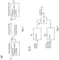
- Fig. 1is a block flow diagram of a broad transmission pre-processing method 100 for out-of-band emission cancellation embodying the invention.
- each of N subchannel symbolsis weighted by a calculated value in the range 0 to 1.
- the weighted symbolsare precoded by multiplication by a unitary matrix.
- a multiband wireless communications system 200 based on OFDMis illustrated in Fig. 2 .
- the system 200includes two communicating nodes: one is the source node 202 and the other is the destination node 204.
- the source node 202transmits data information in multiple frequency bands, and the destination node 204 receives data information from at least one of the multiple frequency bands via a forward path 206.
- the destination node 204may also provide channel state information (CSI) to the source node 202, acknowledge the received data packets, and/or transmit data information to the source node in at least one frequency band via a return path 208.
- CSIchannel state information
- Both the source and the destination nodes 202, 204are equipped with single-element antennas or antenna arrays 210, 212, respectively.
- a signal from any frequency band allocated for other usersmust produce as little as possible emission into the frequency bands allocated to the user concerned.
- the permitted transmit power spectral density for a frequency bandis often referred to as the transmit mask.
- the transmit maskWhen data symbols are modulated on multiple subcarriers in a frequency band using the OFDM technique, the out-of-band emission is significant, and the typical transmit mask is often not met due to the slow sidelobe roll-off of the subcarrier. This can lead to intolerable interference to users operating in the adjacent bands, as mentioned above.
- the transceiver 214, 216 at either the source node 202 or the destination node 204includes a transmitter 302 which composes the input data bits 304 to form data packets and transmits the data packets using OFDM modulation in multiple frequency bands, a receiver 306 which receives the CSI, acknowledgement (ACK) information and/or data packets 308 using OFDM demodulation in multiple frequency bands, and a diplexer 310 which switches the signal path between the transmitter 302 and the receiver 306.
- the transmitter 302 and the receiver 306may have different frequency band arrangements for different nodes.
- Fig. 4shows an example of the multiband arrangement 400 for the transmitter 302, where eight bands, numbered 1 to 8, are accommodated but only six bands, numbered 1, 3, 4, 6, 7, and 8, are allocated to one user and bands 2 and 5 are allocated to a different user (i.e., "unallocated" to the first user).
- the receiver 306receives a signal from one or more of the "allocated bands". Any transmitting band must meet a certain transmit mask requirement so as no to interfere with the transmission of other users in any "unallocated band".
- FIG. 5A schematic block diagram of the transmitter 302 providing out-of-band emission cancellation is shown in Fig. 5 .
- the input data bits 304are firstly mapped by a symbol mapping module 502 into data symbols (i.e., complex numbers) using symbol constellation mapping techniques such as binary phase shift keying (BPSK), quadrature phase shift keying (QPSK), or quadrature amplitude modulation (QAM).
- BPSKbinary phase shift keying
- QPSKquadrature phase shift keying
- QAMquadrature amplitude modulation
- the data symbolsare then assigned to N subcarriers in each of the M allocated bands after passing through a serial-to-parallel conversion (S/P) module 504.
- S/Pserial-to-parallel conversion
- IFFTinverse fast Fourier transform
- P/Sparallel-to-serial conversion
- a module 512the OFDM signal 514 has been formed and transmitted by the transmitter antenna 210, 212.
- the RF circuitry chain after the CP insertion module 512is not shown for clarity's sake, however it will be understood that there are IF and/or RF stages present before the antenna. Since there are total M frequency bands, each having N subcarriers, the IFFT size is MN. Nevertheless, each (allocated) band can have a different number of subcarriers.
- the out-of-band emission cancellationis applied to all the allocated bands (e.g., 1, 3-4, and 6-8).
- the pre-processingincludes two steps, performed by the pre-processing module 506 for each subchannel. Therefore, for each subchannel, a symbol weighting module 516 multiplies each of a sequence of N symbols by a weight having a real value in a range from 0 to 1. A limit weight of value 0 means that the symbol is not transmitted whereas a limit weight value of 1 means that the symbol is transmitted with full power. A precoding module 518 then multiplies the weighted symbols by a unitary matrix. This preprocessing is effective to cancel out-of-band emissions.
- "cancel”is not meant in absolute terms, rather in effective engineering terms, and is synonymous with “reduce to a point of insignificance” or the like.
- n subchannelsare those immediately adjacent to one or both band edges, and 1 ⁇ n ⁇ N.
- One embodimentis a single side out-of-band emission cancellation, and the other is a double sided out-of-band emission cancellation.
- the single side out-of-band emission cancellationmay be used when multiple bands are adjacent to each other to form a contiguous larger band and only the bands on the two sides of the larger band are used for out-of-band emission cancellation.
- the double side out-of-band emission cancellationmay be used when a band is standalone with unallocated bands on both sides.
- the double side out-of-band emission cancellationcan be also used by all bands in a contiguous large band.
- the weights and precoding matrixare selected as follows.
- the symbol weighting and precoding processcan be mathematically expressed, in matrix algebra, as U 1 W 1 s . That is, N symbols are organised as a column matrix and multiplied by W 1 , then matrix multiplied by U 1 .
- the weights and precoding matrixare determined only by the number of subcarriers in a transmission band, N, and a predetermined cancellation distance, w.
- the out-of-band cancellationcan be achieved as a function of only these two variables, which are readily known or chosen.
- the weights and the precoding matrixcan be calculated in advance of transmission rather than in real-time, which is advantageous in reserving processing time for data transmission purposes.
- the weights and precoding matrixare selected as follows.
- the weights determined from W 2are all equal to 1 except for two values greater than 0 but less than 1, which means that all data symbols are transmitted but two of them with reduced power. (This is because the rank of c 2 c 2 T trace c 2 c 2 T is 2 and it has only two non-zero eigenvalues.) For further out-of-band emission reduction, the weights which are not equal to 1 can be set to zero, which means that two data symbols can not be transmitted.
- the symbol weighting and precoding processcan be mathematically expressed as U 2 W 2 s .
- the corresponding receiver 306 to receive the signal 514 generated by the transmitter 302 after out-of-band emission cancellationis shown in Fig. 6 .
- the CPs of the received OFDM symbolsare first removed by a CP removal module 602.
- the resulting OFDM symbolsare then converted into the frequency-domain after passing through an S/P module 604 and a Fast Fourier transform (FFT) module 606.
- Subcarriers in each allocated bandare then equalised by a respective channel equalisation module 608 to compensate for the propagation effects.
- the unitary matrix U 1 T (if U 1 is used at the transmitter) or U 2 T (if U 2 is used at the transmitter)is then used in a respective De-precoding module 610 to compensate for the precoding performed at the transmitter 302.
- the transmitted data symbolis recovered after passing through a respective symbol de-weighting module 612, which involves dividing by the corresponding weight for the data symbol if the weight is not zero. All the recovered data symbols 618 are retrieved into data bits after passing through a P/S module 614 and a symbol demapping module 616.
- the two weights not equal to 1are set to zero.
- the parameter wis selected as (N+1)/2, which means that cancellation point(s) is set to the center of the adjacent band(s).
- the multiband arrangement shown in Fig. 4is also used to determine the out-of-band emission in the unallocated bands when the transmitter transmits signals in multiple bands.
- Fig. 9shows the normalized power spectral densities of the signals transmitted in band 1, 3, 4, 6, 7, and 8 with and without using the out-of-band emission cancellation technique.
- the disclosed out-of-band emission cancellation techniquescan be used in fixed point-to-point wireless links such as wireless backhaul to aggregate multiple frequency bands and channels to improve spectral efficiency and increase transmission data rates. They can be also used in cognitive wireless networks involving multiple frequency bands to enable dynamic band allocation and achieve optimized system performance. For instance, consider a cell in a wireless access network, where the spectrum availability is shown in Fig. 4 . Channels/bands 2 and 5 are not available. In order to maximize the spectral efficiency without incurring sophisticated RF filters, the proposed method can be used to generate signals with the spectrum density shown in Fig. 9 .
- the disclosed techniquedoes not use any guard band nor any dedicated frequency-domain or time-domain cancellation symbol, so the system spectral efficiency and power efficiency are improved as compared with other techniques.
- the disclosed techniquesare particularly applicable to the multi-gigabit wireless backhaul and cognitive wireless access systems where the flexibility of using multiple frequency bands is required.
- the techniquescan be also used in any mobile communications system using orthogonal frequency division multiple access (OFDMA), such as the 3GPP's LTE system.
- OFDMAorthogonal frequency division multiple access
- 3GPP's LTE system3GPP's LTE system.
- other applicationsare possible.
Landscapes
- Engineering & Computer Science (AREA)
- Signal Processing (AREA)
- Computer Networks & Wireless Communication (AREA)
- Power Engineering (AREA)
- Physics & Mathematics (AREA)
- Mathematical Physics (AREA)
- Spectroscopy & Molecular Physics (AREA)
- Transmitters (AREA)
- Mobile Radio Communication Systems (AREA)
- Error Detection And Correction (AREA)
- Vehicle Body Suspensions (AREA)
- Magnetic Resonance Imaging Apparatus (AREA)
Description
- The invention relates to multiband wireless communication systems, and particularly to the cancellation of out-of-band emissions.
- Due to the scarcity of radio spectrum resources and the demand for high speed data transmission, wireless communication systems are required to achieve higher spectral efficiency as well as higher power and cost efficiencies. With the advance of digital signal processing and radio technologies, multiband systems have become more and more appealing since they can accommodate wider spectrum for achieving higher data rates and provide more flexible and adaptive use of the existing frequency bands.
- Orthogonal frequency division multiplexing (OFDM) has been widely used in recent times in various single band communications systems, such as the wireless local area networks (WLANs) and the 3rd Generation Partnership Project (3GPP; www.3gpp.org) Long Term Evolution (LTE) systems. OFDM is characterised by adjacent subchannels within a band exhibiting orthogonality. OFDM is also a suitable modulation technique for use in multiband systems due to the flexibility for subcarrier allocation and the implementation simplicity with fast Fourier transform (FFT) as a frequency band can be dynamically selected or de-selected by turning on or off the subcarriers falling in the band according to the band assignment. However, OFDM exhibits out-of-band emission due to the slow side lobe roll-off of the subcarriers, which can cause inter-channel interference without further reduction to meet the transmit mask requirement.
- There are existing techniques for out-of-band emission reduction in OFDM-based multiband systems. The first straightforward technique is to apply notch filters to the unallocated bands. However, a digital implementation of this filter would increase the processing complexity considerably, and an analogue implementation would be costlyand difficult to achieve dynamic band allocation.
- The second technique is to introduce guard bands on the edges of the transmitted signal bands. Unfortunately, this will sacrifice spectral efficiency and may not be able to provide sufficient protection without having significantly large number of subcarriers used for an allocated frequency band.
- The third technique is to perform windowing to the transmitted signal the time-domain. This requires an extended OFDM symbol with extra signal power and causes inter-symbol interference. Guard bands may also need to be used together with windowing to ensure satisfactory out-of-band emission reduction. (See, for example,IEEE Standard 802.11a-1999, "Part 11: Wireless LAN Medium Access Control (MAC) and Physical Layer (PITY) Specifications: High-speed Physical Layer in the 5 GHz Band".)
- The fourth technique is to compose interference cancellation subcarriers and place them on the edges of the transmitted signal bands.This technique not only reduces the spectral efficiency but also degrades the effective signal-to-noise ratio (SNR) ai the receiver since the extra signal power for the cancellation is wasted, (See, for example,S- Bramdcs, L.Cosevic, and M, Schell, "Reduction Out-of-Band Radiation in OFDM Systems by Insertion of Cancellation Carriers, IEEE Communications Letters Vol. 10, No.6, June 2006, pp. 420-422.)
- In a publication byRenhui Xu et. al., "A precoding scheme for DFT-based OFDM to suppress sidelobes", IEEE Communications Center, Piscataway, NJ, US, vol. 13, no. 10, October 2009 (2009-10-01), pages 776-778, XP011278406, ISSN: 1089-7798, DOI:10.1109/LCOMM. 2009.091339, is proposed a precoding scheme to suppress in-band-out-of-subband (IBOSB) sidelobes. The precoding design is based on the generalized eigenvalue problem.
- There is therefore a need for out-of-band emission cancellation techniques which can substantially avoid the problems of the known approaches.
- Any occurrence of the term "embodiment" in the description has to be considered as an "aspect of the invention", the invention being defined in the appended independent claims.
- There is disclosed a transmission signal pre-processing method for out-of-band emission cancellation, comprising, for each ofN sub-channels in a band weighting each of subchannel symbols by a calculated value in the range from 0 to 1; and proceding saidN weighted symbols, by multiplication by a unitary matrix.
- There is yet further disclosed a reception signal processing method for out-of-band emission cancellation comprising de-precoding received symbols by unitary matrix multiplication, where the reception unitary matrix is the transpose of a preceding matrix used at transmission; and de-weighing said de-precoded symbols by dividing by a respective weight used at transmission.
- There is yet further disclosed an out-of-band emission cancellation method comprising: performing mapping of input data bits into time domain data symbol; converting said time domaine symbols into a plurality of subchannels; for each ofN subchannels in a band: weighting each ofN subchannel symbols by 4 calculated value in use range from 0 to 1; and preceeding saidN weighted symbols by multiplication by a unitary matrix; transforming, said precoded subchannels into orthogonal time domain subchannels; and transmitting said time domain subchannels.
- There is yet further disclosed a transmitter comprising: a module performing mapping of input data bits into time domain data symbols; a module converting said time domain symbols into a plurality of subchannels; for each of N subchannels in a band: a module weighting each ofN sub-channel symbols by a calculated value in the range from 0 to 1; and a module preceding saidN weighted symbols by multiplication by a unitary matrix; a module transforming: said preceded subchannels into orthogonal time domain subchannels; and a radio frequency module transmitting said time domain sub-channels.
- There is yet further disclosed a receiver comprising: a radio frequency module receiving a plurality of time domain orthogonal subchannels; a module transforming said received subchannels into frequency domain subchannels; for such ofN sub-channels de-precoding received symbols by unitary matrix multiplication, where the reception unitary matrix is the transpose of a preceding matrix used at transmission; and de-weighting said de-precoded symbole by dividing by a respective weight used at transmission; a module converting said de-weighted symbols into a sequence of symbols; and a module performing mapping of said sequence of symbols to output data bits.
- There is yet further disclosed a transceiver comprising a transmitter and a receiver as immediately above.
- In the drawings:
Fig. 1 is a block diagram of a broad method embodying the invention.Fig. 2 is a schematic block diagram of example multiband transceivers based on OFDM with source and destination nodes.Fig. 3 is a schematic block diagram of an example transceiver.Fig. 4 is an example multiband arrangement.Fig. 5 is a schematic block diagram of an example transmitter with out-of-band emission cancellation.Fig. 6 is a schematic block diagram of an example receiver adapted for out-of-band emission cancellation.Fig. 7 shows the performance of single side out-of-band emission cancellation.Fig. 8 shows the performance of double side out-of-band emission cancellation.Fig. 9 shows out-of-band emission in unallocated bands under the multiband arrangement shown inFig. 4 .- Where reference is made in any one or more of the accompanying diagrams to steps and/or features which have the same reference numerals, those steps and/or features have for the purpose of this description the same functions(s) or operations(s), unless the contrary intention appears.
- In what follows, the expression "module" is to be understood as a general term for circuit elements, which can be implemented in many convenient forms, such as software running on a processor, firmware and FPGAs in the digital domain, and as discrete circuits in the analogue domain. Also, matrix algebra when implemented in code or circuitry can be done in many convenient forms, involving multiplication and addition operations, as would be apparent to a person of ordinary skill in the art..
Fig. 1 is a block flow diagram of a broad transmission pre-processingmethod 100 for out-of-band emission cancellation embodying the invention. For each ofN subchannels in a band, atstep 102 each of N subchannel symbols is weighted by a calculated value in therange 0 to 1. Atstep 104, the weighted symbols are precoded by multiplication by a unitary matrix.- A multiband
wireless communications system 200 based on OFDM is illustrated inFig. 2 . Thesystem 200 includes two communicating nodes: one is thesource node 202 and the other is thedestination node 204. Thesource node 202 transmits data information in multiple frequency bands, and thedestination node 204 receives data information from at least one of the multiple frequency bands via aforward path 206. Thedestination node 204 may also provide channel state information (CSI) to thesource node 202, acknowledge the received data packets, and/or transmit data information to the source node in at least one frequency band via areturn path 208. Both the source and thedestination nodes antenna arrays 210, 212, respectively. To reduce the inter-channel interference at the receiver (within the source anddestination transceivers 214, 216), a signal from any frequency band allocated for other users must produce as little as possible emission into the frequency bands allocated to the user concerned. The permitted transmit power spectral density for a frequency band is often referred to as the transmit mask. When data symbols are modulated on multiple subcarriers in a frequency band using the OFDM technique, the out-of-band emission is significant, and the typical transmit mask is often not met due to the slow sidelobe roll-off of the subcarrier. This can lead to intolerable interference to users operating in the adjacent bands, as mentioned above. - As shown in
Fig. 3 , thetransceiver source node 202 or thedestination node 204 includes atransmitter 302 which composes theinput data bits 304 to form data packets and transmits the data packets using OFDM modulation in multiple frequency bands, areceiver 306 which receives the CSI, acknowledgement (ACK) information and/ordata packets 308 using OFDM demodulation in multiple frequency bands, and adiplexer 310 which switches the signal path between thetransmitter 302 and thereceiver 306. - The
transmitter 302 and thereceiver 306 may have different frequency band arrangements for different nodes.Fig. 4 shows an example of themultiband arrangement 400 for thetransmitter 302, where eight bands, numbered 1 to 8, are accommodated but only six bands, numbered 1, 3, 4, 6, 7, and 8, are allocated to one user andbands receiver 306 receives a signal from one or more of the "allocated bands". Any transmitting band must meet a certain transmit mask requirement so as no to interfere with the transmission of other users in any "unallocated band". - A schematic block diagram of the
transmitter 302 providing out-of-band emission cancellation is shown inFig. 5 . Theinput data bits 304 are firstly mapped by asymbol mapping module 502 into data symbols (i.e., complex numbers) using symbol constellation mapping techniques such as binary phase shift keying (BPSK), quadrature phase shift keying (QPSK), or quadrature amplitude modulation (QAM). The data symbols are then assigned to N subcarriers in each of the M allocated bands after passing through a serial-to-parallel conversion (S/P)module 504. (The subcarriers in the unallocated bands are nulled.) After the out-of-band emission cancellation is performed (by the groupedmodule 506, to be described later), an inverse fast Fourier transform (IFFT) is performed by anIFFT module 508, followed by a parallel-to-serial conversion (P/S) by amodule 510, to convert the frequency domain symbols to time domain samples. After cyclic prefix insertion by amodule 512, theOFDM signal 514 has been formed and transmitted by thetransmitter antenna 210, 212. The RF circuitry chain after theCP insertion module 512 is not shown for clarity's sake, however it will be understood that there are IF and/or RF stages present before the antenna. Since there are total M frequency bands, each having N subcarriers, the IFFT size is MN. Nevertheless, each (allocated) band can have a different number of subcarriers. - The out-of-band emission cancellation is applied to all the allocated bands (e.g., 1, 3-4, and 6-8). The pre-processing includes two steps, performed by the
pre-processing module 506 for each subchannel. Therefore, for each subchannel, asymbol weighting module 516 multiplies each of a sequence of N symbols by a weight having a real value in a range from 0 to 1. A limit weight ofvalue 0 means that the symbol is not transmitted whereas a limit weight value of 1 means that the symbol is transmitted with full power. Aprecoding module 518 then multiplies the weighted symbols by a unitary matrix. This preprocessing is effective to cancel out-of-band emissions. Here, "cancel" is not meant in absolute terms, rather in effective engineering terms, and is synonymous with "reduce to a point of insignificance" or the like. - In another form, only a subset n of the N subchannels within a band is subjected to the pre-processing. The n subchannels are those immediately adjacent to one or both band edges, and 1≤n<<N.
- Two embodiments of weight selection and choice of precoding matrix will now be described. One embodiment is a single side out-of-band emission cancellation, and the other is a double sided out-of-band emission cancellation. The single side out-of-band emission cancellation may be used when multiple bands are adjacent to each other to form a contiguous larger band and only the bands on the two sides of the larger band are used for out-of-band emission cancellation. The double side out-of-band emission cancellation may be used when a band is standalone with unallocated bands on both sides. However, the double side out-of-band emission cancellation can be also used by all bands in a contiguous large band.
- For the single side out-of-band emission cancellation, the weights and precoding matrix are selected as follows.
- 1. Define an N-by-1
vector 

- 2. Perform singular value decomposition for matrix


- 3. The diagonal elements inW1 are utilised as the weights andU1 is utilised as the precoding matrix for the single side out-of-band emission cancellation.
- It is evident from (2) that the weights determined fromW1 are all equal to 1 except for one zero, which means that one data symbol can not be transmitted. (This is because the rank of

non-zero eigenvalue 1.) In other words, each of the N subcarriers can only transmit N-1 data symbols. - Suppose that the data symbolsso' sl, ...,SN-1 can be expressed as a vectors=(s0,s1,···,sN-1)T.The symbol weighting and precoding process can be mathematically expressed, in matrix algebra, asU1W1s. That is, N symbols are organised as a column matrix and multiplied byW1, then matrix multiplied byU1.
- Note also from (2) that the weights and precoding matrix are determined only by the number of subcarriers in a transmission band, N, and a predetermined cancellation distance, w. In other words, the out-of-band cancellation can be achieved as a function of only these two variables, which are readily known or chosen. The weights and the precoding matrix can be calculated in advance of transmission rather than in real-time, which is advantageous in reserving processing time for data transmission purposes.
- For the double side out-of-band emission cancellation, the weights and precoding matrix are selected as follows.
- 1. Define an N-by-2
vector 
- 2. Perform singular value decomposition for matrix


- 3. The diagonal elements inW2 are the weights andU2 is the precoding matrix for the double side out-of-band emission cancellation.
- It is evident from (4) that the weights determined fromW2 are all equal to 1 except for two values greater than 0 but less than 1, which means that all data symbols are transmitted but two of them with reduced power. (This is because the rank of

- Similarly, the symbol weighting and precoding process can be mathematically expressed asU2W2s.
- The corresponding
receiver 306 to receive thesignal 514 generated by thetransmitter 302 after out-of-band emission cancellation is shown inFig. 6 . The CPs of the received OFDM symbols are first removed by aCP removal module 602. The resulting OFDM symbols are then converted into the frequency-domain after passing through an S/P module 604 and a Fast Fourier transform (FFT)module 606. Subcarriers in each allocated band are then equalised by a respectivechannel equalisation module 608 to compensate for the propagation effects. The unitary matrixU1T (ifU1 is used at the transmitter) orU2T (ifU2 is used at the transmitter) is then used in a respectiveDe-precoding module 610 to compensate for the precoding performed at thetransmitter 302. The transmitted data symbol is recovered after passing through a respectivesymbol de-weighting module 612, which involves dividing by the corresponding weight for the data symbol if the weight is not zero. All the recovereddata symbols 618 are retrieved into data bits after passing through a P/S module 614 and asymbol demapping module 616. - To demonstrate the performance of the disclosed out-of-band emission cancellation technique,
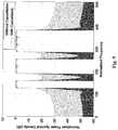
Figs. 7 and8 show the normalized power spectral densities of a transmitted signal in a frequency band with N=32 subcarriers after single side out-of-band emission cancellation and double side out-of-band emission cancellation respectively. For the double side out-of-band emission cancellation, the two weights not equal to 1 are set to zero. The parameterw is selected as (N+1)/2, which means that cancellation point(s) is set to the center of the adjacent band(s). It is observed that using the single side out-of-band emission cancellation the power spectral density is reduced by about 10 dB as compared with the one without cancellation, whereas using the double side out-of-band emission cancellation the power spectral density is reduced by about 20 dB. - The multiband arrangement shown in
Fig. 4 is also used to determine the out-of-band emission in the unallocated bands when the transmitter transmits signals in multiple bands.Fig. 9 shows the normalized power spectral densities of the signals transmitted inband unallocated band - The disclosed out-of-band emission cancellation techniques can be used in fixed point-to-point wireless links such as wireless backhaul to aggregate multiple frequency bands and channels to improve spectral efficiency and increase transmission data rates. They can be also used in cognitive wireless networks involving multiple frequency bands to enable dynamic band allocation and achieve optimized system performance. For instance, consider a cell in a wireless access network, where the spectrum availability is shown in
Fig. 4 . Channels/bands Fig. 9 . - The disclosed technique does not use any guard band nor any dedicated frequency-domain or time-domain cancellation symbol, so the system spectral efficiency and power efficiency are improved as compared with other techniques.
- The disclosed techniques are particularly applicable to the multi-gigabit wireless backhaul and cognitive wireless access systems where the flexibility of using multiple frequency bands is required. The techniques can be also used in any mobile communications system using orthogonal frequency division multiple access (OFDMA), such as the 3GPP's LTE system. Of course, other applications are possible.
- The foregoing describes some embodiments that are illustrative and not restrictive on the scope of the invention.


Claims (12)
- A transmission signal pre-processing method (100) for out-of-band emission cancellation,characterized in that the method comprises the steps of weighting (102) each of N subchannel symbols in a band by a calculated value, wherein weighting by the value 0 cancels the subchannel symbol and weighting by the value 1 results in the subchannel symbol being transmitted at full power; and
precoding (104) said weighted symbols organised as a Nx1 matrix, by multiplication by a NxN unitary matrix,
wherein said calculated values are organised as a NxN diagonal matrix, and said weighting is performed by multiplying the symbols matrix and the diagonal matrix,
wherein an identity matrix of order N and a correction expression are the subject of singular value decomposition to give said diagonal matrix and said unitary matrix, the singular value decomposition being performed on a matrix of the form:
- A method according to claim 1, wherein said n subchannels in frequency are located immediately adjacent to a band edge.
- An out-of-band emission cancellation method,characterized in that the method comprises the steps of
performing mapping (502) of input data bits (304) into time domain data symbols; converting (504) said time domain symbols into a plurality of subchannels; and
for each of N subchannels in a band:weighting (516) each of N subchannel symbols by a calculated value, wherein weighting by the value 0 cancels the subchannel symbol and weighting by the value 1 results in the subchannel symbol being transmitted at full power; andprecoding (518) said N weighted symbols by multiplication by a unitary matrix;transforming (508, 510) said precoded subchannels into orthogonal time domain subchannels; and
transmitting (210, 212) said time domain subchannels,
wherein said calculated values are organised an a NxN diagonal matrix, and said weighting is performed by multiplying the symbols matrix and the diagonal matrix,
wherein an identity matrix of order N and a correction expression are the subject of singular value decomposition to give said diagonal matrix and said unitary matrix, the singular value decomposition being performed on a matrix of the form:
- A method according to claim 1 or claim 3, performed in an Orthogonal Frequency Division Multiplexing (OFDM) scheme.
- A method according to claim 1 or 3, wherein and said correction expression is of the form:

- A method according to claim 1 or 3, wherein said correction expression is of the form:

- A transmitter (302) for out-of-band emission cancellation,characterized in that the transmitter comprises
a module performing mapping (502) of input data bits (304) into time domain data symbols;
a module converting (504) said time domain symbols into a plurality of subchannels;
for each of N subchannels in a band:a module weighting (516) each of N subchannel symbols by a calculated value wherein weighting by the value 0 cancels the subchannel symbol and weighting by the value 1 results in the subchannel symbol being transmitted at full power; anda module precoding (518) said N weighted symbols by multiplication by a unitary matrix;a module transforming (508, 510) said precoded subchannels into orthogonal time domain subchannels (514); and
a radio frequency module transmitting (210, 212) said time domain subchannels,
wherein said calculated values are organised an a NxN diagonal matrix, and said weighting is performed by multiplying the symbols matrix and the diagonal matrix,
wherein an identity matrix of order N and a correction expression are the subject of singular value decomposition to give said diagonal matrix and said unitary matrix, the singular value decomposition being performed on a matrix of the form:
- A transmitter according to claim 7, wherein said transforming module is an inverse fast Fourier transform circuit.
- A transmitter according to claim 7, wherein said correction expression is of the form:

- A transmitter according to claim 7, wherein said correction expression is of the form:

- A receiver (306) for out-of-band emission cancellation,characterized in that the transmitter comprises
a radio frequency module receiving (210, 212) a plurality of time domain orthogonal subchannels (514);
a module transforming (604, 606) said received subchannels into frequency domain subchannels;
for each of N subchannels:a module de-precoding (610) received symbols by unitary matrix multiplication, where the reception unitary matrix is the transpose of a precoding matrix used at transmission; anda module de-weighting (612) said de-precoded symbols by dividing by a respective weight used at transmission, wherein each respective weight has a respective value, wherein weighting by the value 0 during transmission cancels the symbol and weighting during transmission by the value 1 results in the symbol being transmitted at full power;a module converting (614) said de-weighted symbols into a sequence of symbols; and
a module performing de-mapping (616) of said sequence of symbols to output data bits (618), wherein said N subchannel symbols are organised as a Nx1 matrix and said weights are organised an a NxN diagonal matrix, and said weighting is performed by multiplying the symbols matrix and the diagonal matrix,
wherein an identity matrix of order N and a correction expression are the subject of singular value decomposition to give said diagonal matrix and said unitary matrix, the singular value decomposition being performed on a matrix of the form:
- A transceiver for out-of-band emission cancellation, comprising a transmitter of any one of claims 7, 8, 9, and 10 and a receiver of claim 11.


Applications Claiming Priority (3)
| Application Number | Priority Date | Filing Date | Title |
|---|---|---|---|
| US25677809P | 2009-10-30 | 2009-10-30 | |
| AU2009905333AAU2009905333A0 (en) | 2009-10-30 | Out-of-band emission cancellation | |
| PCT/AU2010/001356WO2011050392A1 (en) | 2009-10-30 | 2010-10-14 | Out-of-band emission cancellation |
Publications (3)
| Publication Number | Publication Date |
|---|---|
| EP2494756A1 EP2494756A1 (en) | 2012-09-05 |
| EP2494756A4 EP2494756A4 (en) | 2013-12-25 |
| EP2494756B1true EP2494756B1 (en) | 2016-12-21 |
Family
ID=43921145
Family Applications (1)
| Application Number | Title | Priority Date | Filing Date |
|---|---|---|---|
| EP10825838.5AActiveEP2494756B1 (en) | 2009-10-30 | 2010-10-14 | Out-of-band emission cancellation |
Country Status (6)
| Country | Link |
|---|---|
| US (1) | US9240910B2 (en) |
| EP (1) | EP2494756B1 (en) |
| JP (1) | JP5809632B2 (en) |
| CN (1) | CN102835083B (en) |
| AU (1) | AU2010312304B2 (en) |
| WO (1) | WO2011050392A1 (en) |
Families Citing this family (14)
| Publication number | Priority date | Publication date | Assignee | Title |
|---|---|---|---|---|
| EP2319218B1 (en)* | 2008-08-05 | 2013-04-10 | Huawei Technologies Co., Ltd. | Method, apparatus and product of OFDM transmission |
| KR102134657B1 (en)* | 2010-12-10 | 2020-07-16 | 선 페이턴트 트러스트 | Communication apparatus and communication method |
| CA2862474C (en) | 2011-01-27 | 2020-04-07 | Commonwealth Scientific And Industrial Research Organisation | Reducing out-of-band emission |
| CN102986184A (en)* | 2011-06-23 | 2013-03-20 | 华为技术有限公司 | Method for suppressing out-of-band radiation, receiver, transmitter and a communication system |
| US8737458B2 (en) | 2012-06-20 | 2014-05-27 | MagnaCom Ltd. | Highly-spectrally-efficient reception using orthogonal frequency division multiplexing |
| US8559498B1 (en) | 2012-06-20 | 2013-10-15 | MagnaCom Ltd. | Decision feedback equalizer utilizing symbol error rate biased adaptation function for highly spectrally efficient communications |
| US9118519B2 (en) | 2013-11-01 | 2015-08-25 | MagnaCom Ltd. | Reception of inter-symbol-correlated signals using symbol-by-symbol soft-output demodulator |
| TWI523466B (en)* | 2014-03-13 | 2016-02-21 | 國立臺灣大學 | Transmission circuit for spectrally precoded orthogonal frequency division multiple access with interleaved subcarrier allocation |
| US9496900B2 (en) | 2014-05-06 | 2016-11-15 | MagnaCom Ltd. | Signal acquisition in a multimode environment |
| US9246523B1 (en) | 2014-08-27 | 2016-01-26 | MagnaCom Ltd. | Transmitter signal shaping |
| US9843959B2 (en)* | 2015-09-30 | 2017-12-12 | Intel IP Corporation | Interference mitigation by a scalable digital wireless modem |
| CN107370704A (en)* | 2016-05-13 | 2017-11-21 | 财团法人工业技术研究院 | Wireless communication apparatus and wireless signal generating method |
| WO2018027261A1 (en)* | 2016-08-08 | 2018-02-15 | The University Of Queensland | Orthogonal precoding for sidelobe suppression |
| EP3577866B1 (en)* | 2017-02-06 | 2022-01-19 | Telefonaktiebolaget LM Ericsson (Publ) | Systems and methods for minimizing performance impact from known signal distortions |
Family Cites Families (21)
| Publication number | Priority date | Publication date | Assignee | Title |
|---|---|---|---|---|
| US6081697A (en) | 1997-03-21 | 2000-06-27 | Telefonaktiebolaget Lm Ericsson | Multi-carrier radio system and radio transceiver implementation |
| DE10112025A1 (en) | 2001-03-06 | 2002-09-19 | Deutsche Telekom Ag | Method for reducing the out-of-band radiation in AM transmitters for digital transmission |
| US6985704B2 (en) | 2002-05-01 | 2006-01-10 | Dali Yang | System and method for digital memorized predistortion for wireless communication |
| US7613248B2 (en)* | 2002-06-24 | 2009-11-03 | Qualcomm Incorporated | Signal processing with channel eigenmode decomposition and channel inversion for MIMO systems |
| US7013161B2 (en) | 2002-09-24 | 2006-03-14 | Nortel Networks Limited | Peak power reduction using windowing and filtering |
| GB2401516A (en) | 2003-04-17 | 2004-11-10 | Univ Southampton | Peak-to-average power ratio reduction by subtracting shaped pulses from a baseband signal |
| US7409010B2 (en) | 2003-06-10 | 2008-08-05 | Shared Spectrum Company | Method and system for transmitting signals with reduced spurious emissions |
| DE60335666D1 (en)* | 2003-08-29 | 2011-02-17 | Nat Inst Inf & Comm Tech | TRANSMITTER, RECEIVER, TRANSMISSION, RECEIVING METHOD AND PROGRAM |
| US7542517B2 (en) | 2004-02-02 | 2009-06-02 | Ibiquity Digital Corporation | Peak-to-average power reduction for FM OFDM transmission |
| US7403470B2 (en) | 2005-06-13 | 2008-07-22 | Qualcomm Incorporated | Communications system, methods and apparatus |
| US7574224B2 (en) | 2005-06-13 | 2009-08-11 | Qualcomm Incorporated | Methods and apparatus for performing timing synchronization with base stations |
| US7542736B2 (en) | 2005-07-26 | 2009-06-02 | M/A-Com, Inc. | Techniques to decrease signal amplitude peak-to-average ratio in a wireless communications system |
| US8760994B2 (en)* | 2005-10-28 | 2014-06-24 | Qualcomm Incorporated | Unitary precoding based on randomized FFT matrices |
| US20070110135A1 (en)* | 2005-11-15 | 2007-05-17 | Tommy Guess | Iterative interference cancellation for MIMO-OFDM receivers |
| WO2007081173A2 (en)* | 2006-01-13 | 2007-07-19 | Electronics And Telecommunications Research Institute | Method and apparatus for generating and receiving ofdm symbol |
| CN101056151B (en)* | 2006-04-10 | 2010-09-08 | 中国科学院上海微系统与信息技术研究所 | Multicast Unicast Compatible Orthogonal Frequency Division Time Division Multiplexing Transmitter, Receiver and Method |
| WO2008032407A1 (en)* | 2006-09-15 | 2008-03-20 | Fujitsu Limited | Apparatus and method for transmitting signals by use of multicarrier system |
| KR101163280B1 (en)* | 2006-10-03 | 2012-07-10 | 인터디지탈 테크날러지 코포레이션 | Combined open loop/closed loop cqi-based uplink transmit power control with interference mitigation for e-utra |
| EP2266214B1 (en)* | 2008-03-28 | 2012-11-07 | Huawei Technologies Co., Ltd. | Reduction of out-of-band emitted power |
| US8175035B2 (en)* | 2008-10-31 | 2012-05-08 | Mitsubishi Electric Research Laboratories, Inc. | Dynamic fractional frequency reuse in OFDMA networks |
| WO2011002355A1 (en)* | 2009-06-29 | 2011-01-06 | Telefonaktiebolaget L M Ericsson (Publ) | Method and arrangement for adapting a signal in a wireless communications network |
- 2010
- 2010-10-14EPEP10825838.5Apatent/EP2494756B1/enactiveActive
- 2010-10-14AUAU2010312304Apatent/AU2010312304B2/ennot_activeCeased
- 2010-10-14JPJP2012535542Apatent/JP5809632B2/enactiveActive
- 2010-10-14WOPCT/AU2010/001356patent/WO2011050392A1/enactiveApplication Filing
- 2010-10-14USUS13/504,456patent/US9240910B2/enactiveActive
- 2010-10-14CNCN201080052120.6Apatent/CN102835083B/enactiveActive
Non-Patent Citations (1)
| Title |
|---|
| None* |
Also Published As
| Publication number | Publication date |
|---|---|
| JP2013509112A (en) | 2013-03-07 |
| EP2494756A4 (en) | 2013-12-25 |
| AU2010312304B2 (en) | 2016-07-14 |
| US20120269286A1 (en) | 2012-10-25 |
| WO2011050392A1 (en) | 2011-05-05 |
| CN102835083B (en) | 2016-01-13 |
| CN102835083A (en) | 2012-12-19 |
| EP2494756A1 (en) | 2012-09-05 |
| US9240910B2 (en) | 2016-01-19 |
| AU2010312304A1 (en) | 2012-05-31 |
| JP5809632B2 (en) | 2015-11-11 |
Similar Documents
| Publication | Publication Date | Title |
|---|---|---|
| EP2494756B1 (en) | Out-of-band emission cancellation | |
| US10411935B2 (en) | System and method for DFT-S-OFDM PAPR reduction | |
| US8660197B2 (en) | Method of and equipment for compensating carrier frequency offset in an orthogonal frequency division multiplexing wireless radio transmission system | |
| CN105530217B (en) | The signal of GFDM systems based on weighted score Fourier transformation emits and method of reseptance | |
| US8520750B2 (en) | Transmission method and apparatus for cancelling inter-carrier interference | |
| US8107356B2 (en) | Method and apparatus for transmitting/receiving a signal in an FFH-OFDM communication system | |
| KR102542702B1 (en) | Methods and apparatus of repeated transmission for multicarrier wireless communication systems | |
| EP3278524B1 (en) | Method and apparatus for peak to average power reduction in wireless communication systems using spectral mask filling | |
| EP2352246B1 (en) | Multi-user mimo system, receiver apparatus and transmitter apparatus | |
| US10581546B2 (en) | Transmitter, transmission method, and receiver based on time-domain windows | |
| US9893923B2 (en) | Method for transmitting and receiving QAM signal in filter bank-based multicarrier communication system, and apparatus therefor | |
| Anughna et al. | Performance analysis on 5g waveform candidates for mimo technologies | |
| US10742454B2 (en) | Transmission device, transmission method, reception device, and reception method | |
| Mustafa et al. | Various Technologies used in 5G Communication and the Issues Related to it | |
| Lian et al. | Adaptive OFDM beamformer with constrained weights for cognitive radio | |
| Wu et al. | Waveform and Modulation Design of Terahertz Communications | |
| KR20080106489A (en) | Transmission Power Allocation Method for Improving Bit Error Rate Performance of Multiple Input Multiple Output Orthogonal Frequency Division Multiplexing Systems | |
| YK et al. | Intrinsic interference suppressed FBMC QAM for MU-MIMO systems in computing and communications | |
| Khan et al. | Beamforming for rejection of co-channels interference in an OFDM system | |
| EP3282655A1 (en) | Suppression of out of band emissions using cancellation subcarriers in guard band |
Legal Events
| Date | Code | Title | Description |
|---|---|---|---|
| PUAI | Public reference made under article 153(3) epc to a published international application that has entered the european phase | Free format text:ORIGINAL CODE: 0009012 | |
| 17P | Request for examination filed | Effective date:20120530 | |
| AK | Designated contracting states | Kind code of ref document:A1 Designated state(s):AL AT BE BG CH CY CZ DE DK EE ES FI FR GB GR HR HU IE IS IT LI LT LU LV MC MK MT NL NO PL PT RO RS SE SI SK SM TR | |
| DAX | Request for extension of the european patent (deleted) | ||
| A4 | Supplementary search report drawn up and despatched | Effective date:20131127 | |
| RIC1 | Information provided on ipc code assigned before grant | Ipc:H04J 1/00 20060101ALI20131121BHEP Ipc:H04B 7/00 20060101ALI20131121BHEP Ipc:H04J 11/00 20060101ALI20131121BHEP Ipc:H04L 27/26 20060101AFI20131121BHEP | |
| 17Q | First examination report despatched | Effective date:20140709 | |
| GRAP | Despatch of communication of intention to grant a patent | Free format text:ORIGINAL CODE: EPIDOSNIGR1 | |
| INTG | Intention to grant announced | Effective date:20160715 | |
| GRAS | Grant fee paid | Free format text:ORIGINAL CODE: EPIDOSNIGR3 | |
| GRAA | (expected) grant | Free format text:ORIGINAL CODE: 0009210 | |
| AK | Designated contracting states | Kind code of ref document:B1 Designated state(s):AL AT BE BG CH CY CZ DE DK EE ES FI FR GB GR HR HU IE IS IT LI LT LU LV MC MK MT NL NO PL PT RO RS SE SI SK SM TR | |
| REG | Reference to a national code | Ref country code:GB Ref legal event code:FG4D | |
| REG | Reference to a national code | Ref country code:CH Ref legal event code:EP | |
| REG | Reference to a national code | Ref country code:IE Ref legal event code:FG4D | |
| REG | Reference to a national code | Ref country code:AT Ref legal event code:REF Ref document number:856338 Country of ref document:AT Kind code of ref document:T Effective date:20170115 | |
| REG | Reference to a national code | Ref country code:DE Ref legal event code:R096 Ref document number:602010039053 Country of ref document:DE | |
| PG25 | Lapsed in a contracting state [announced via postgrant information from national office to epo] | Ref country code:LV Free format text:LAPSE BECAUSE OF FAILURE TO SUBMIT A TRANSLATION OF THE DESCRIPTION OR TO PAY THE FEE WITHIN THE PRESCRIBED TIME-LIMIT Effective date:20161221 | |
| REG | Reference to a national code | Ref country code:LT Ref legal event code:MG4D | |
| REG | Reference to a national code | Ref country code:NL Ref legal event code:MP Effective date:20161221 | |
| PG25 | Lapsed in a contracting state [announced via postgrant information from national office to epo] | Ref country code:LT Free format text:LAPSE BECAUSE OF FAILURE TO SUBMIT A TRANSLATION OF THE DESCRIPTION OR TO PAY THE FEE WITHIN THE PRESCRIBED TIME-LIMIT Effective date:20161221 Ref country code:SE Free format text:LAPSE BECAUSE OF FAILURE TO SUBMIT A TRANSLATION OF THE DESCRIPTION OR TO PAY THE FEE WITHIN THE PRESCRIBED TIME-LIMIT Effective date:20161221 Ref country code:GR Free format text:LAPSE BECAUSE OF FAILURE TO SUBMIT A TRANSLATION OF THE DESCRIPTION OR TO PAY THE FEE WITHIN THE PRESCRIBED TIME-LIMIT Effective date:20170322 Ref country code:NO Free format text:LAPSE BECAUSE OF FAILURE TO SUBMIT A TRANSLATION OF THE DESCRIPTION OR TO PAY THE FEE WITHIN THE PRESCRIBED TIME-LIMIT Effective date:20170321 | |
| REG | Reference to a national code | Ref country code:AT Ref legal event code:MK05 Ref document number:856338 Country of ref document:AT Kind code of ref document:T Effective date:20161221 | |
| PG25 | Lapsed in a contracting state [announced via postgrant information from national office to epo] | Ref country code:HR Free format text:LAPSE BECAUSE OF FAILURE TO SUBMIT A TRANSLATION OF THE DESCRIPTION OR TO PAY THE FEE WITHIN THE PRESCRIBED TIME-LIMIT Effective date:20161221 Ref country code:RS Free format text:LAPSE BECAUSE OF FAILURE TO SUBMIT A TRANSLATION OF THE DESCRIPTION OR TO PAY THE FEE WITHIN THE PRESCRIBED TIME-LIMIT Effective date:20161221 Ref country code:FI Free format text:LAPSE BECAUSE OF FAILURE TO SUBMIT A TRANSLATION OF THE DESCRIPTION OR TO PAY THE FEE WITHIN THE PRESCRIBED TIME-LIMIT Effective date:20161221 | |
| PG25 | Lapsed in a contracting state [announced via postgrant information from national office to epo] | Ref country code:NL Free format text:LAPSE BECAUSE OF FAILURE TO SUBMIT A TRANSLATION OF THE DESCRIPTION OR TO PAY THE FEE WITHIN THE PRESCRIBED TIME-LIMIT Effective date:20161221 | |
| PG25 | Lapsed in a contracting state [announced via postgrant information from national office to epo] | Ref country code:SK Free format text:LAPSE BECAUSE OF FAILURE TO SUBMIT A TRANSLATION OF THE DESCRIPTION OR TO PAY THE FEE WITHIN THE PRESCRIBED TIME-LIMIT Effective date:20161221 Ref country code:IS Free format text:LAPSE BECAUSE OF FAILURE TO SUBMIT A TRANSLATION OF THE DESCRIPTION OR TO PAY THE FEE WITHIN THE PRESCRIBED TIME-LIMIT Effective date:20170421 Ref country code:CZ Free format text:LAPSE BECAUSE OF FAILURE TO SUBMIT A TRANSLATION OF THE DESCRIPTION OR TO PAY THE FEE WITHIN THE PRESCRIBED TIME-LIMIT Effective date:20161221 Ref country code:EE Free format text:LAPSE BECAUSE OF FAILURE TO SUBMIT A TRANSLATION OF THE DESCRIPTION OR TO PAY THE FEE WITHIN THE PRESCRIBED TIME-LIMIT Effective date:20161221 Ref country code:RO Free format text:LAPSE BECAUSE OF FAILURE TO SUBMIT A TRANSLATION OF THE DESCRIPTION OR TO PAY THE FEE WITHIN THE PRESCRIBED TIME-LIMIT Effective date:20161221 | |
| PG25 | Lapsed in a contracting state [announced via postgrant information from national office to epo] | Ref country code:BE Free format text:LAPSE BECAUSE OF FAILURE TO SUBMIT A TRANSLATION OF THE DESCRIPTION OR TO PAY THE FEE WITHIN THE PRESCRIBED TIME-LIMIT Effective date:20161221 Ref country code:BG Free format text:LAPSE BECAUSE OF FAILURE TO SUBMIT A TRANSLATION OF THE DESCRIPTION OR TO PAY THE FEE WITHIN THE PRESCRIBED TIME-LIMIT Effective date:20170321 Ref country code:PT Free format text:LAPSE BECAUSE OF FAILURE TO SUBMIT A TRANSLATION OF THE DESCRIPTION OR TO PAY THE FEE WITHIN THE PRESCRIBED TIME-LIMIT Effective date:20170421 Ref country code:AT Free format text:LAPSE BECAUSE OF FAILURE TO SUBMIT A TRANSLATION OF THE DESCRIPTION OR TO PAY THE FEE WITHIN THE PRESCRIBED TIME-LIMIT Effective date:20161221 Ref country code:ES Free format text:LAPSE BECAUSE OF FAILURE TO SUBMIT A TRANSLATION OF THE DESCRIPTION OR TO PAY THE FEE WITHIN THE PRESCRIBED TIME-LIMIT Effective date:20161221 Ref country code:IT Free format text:LAPSE BECAUSE OF FAILURE TO SUBMIT A TRANSLATION OF THE DESCRIPTION OR TO PAY THE FEE WITHIN THE PRESCRIBED TIME-LIMIT Effective date:20161221 Ref country code:PL Free format text:LAPSE BECAUSE OF FAILURE TO SUBMIT A TRANSLATION OF THE DESCRIPTION OR TO PAY THE FEE WITHIN THE PRESCRIBED TIME-LIMIT Effective date:20161221 Ref country code:SM Free format text:LAPSE BECAUSE OF FAILURE TO SUBMIT A TRANSLATION OF THE DESCRIPTION OR TO PAY THE FEE WITHIN THE PRESCRIBED TIME-LIMIT Effective date:20161221 | |
| REG | Reference to a national code | Ref country code:DE Ref legal event code:R097 Ref document number:602010039053 Country of ref document:DE | |
| REG | Reference to a national code | Ref country code:FR Ref legal event code:PLFP Year of fee payment:8 | |
| PLBE | No opposition filed within time limit | Free format text:ORIGINAL CODE: 0009261 | |
| STAA | Information on the status of an ep patent application or granted ep patent | Free format text:STATUS: NO OPPOSITION FILED WITHIN TIME LIMIT | |
| 26N | No opposition filed | Effective date:20170922 | |
| PG25 | Lapsed in a contracting state [announced via postgrant information from national office to epo] | Ref country code:DK Free format text:LAPSE BECAUSE OF FAILURE TO SUBMIT A TRANSLATION OF THE DESCRIPTION OR TO PAY THE FEE WITHIN THE PRESCRIBED TIME-LIMIT Effective date:20161221 | |
| PG25 | Lapsed in a contracting state [announced via postgrant information from national office to epo] | Ref country code:SI Free format text:LAPSE BECAUSE OF FAILURE TO SUBMIT A TRANSLATION OF THE DESCRIPTION OR TO PAY THE FEE WITHIN THE PRESCRIBED TIME-LIMIT Effective date:20161221 | |
| PG25 | Lapsed in a contracting state [announced via postgrant information from national office to epo] | Ref country code:MC Free format text:LAPSE BECAUSE OF FAILURE TO SUBMIT A TRANSLATION OF THE DESCRIPTION OR TO PAY THE FEE WITHIN THE PRESCRIBED TIME-LIMIT Effective date:20161221 | |
| REG | Reference to a national code | Ref country code:CH Ref legal event code:PL | |
| REG | Reference to a national code | Ref country code:IE Ref legal event code:MM4A | |
| PG25 | Lapsed in a contracting state [announced via postgrant information from national office to epo] | Ref country code:LU Free format text:LAPSE BECAUSE OF NON-PAYMENT OF DUE FEES Effective date:20171014 Ref country code:CH Free format text:LAPSE BECAUSE OF NON-PAYMENT OF DUE FEES Effective date:20171031 Ref country code:LI Free format text:LAPSE BECAUSE OF NON-PAYMENT OF DUE FEES Effective date:20171031 | |
| PG25 | Lapsed in a contracting state [announced via postgrant information from national office to epo] | Ref country code:MT Free format text:LAPSE BECAUSE OF NON-PAYMENT OF DUE FEES Effective date:20171014 | |
| REG | Reference to a national code | Ref country code:FR Ref legal event code:PLFP Year of fee payment:9 | |
| PG25 | Lapsed in a contracting state [announced via postgrant information from national office to epo] | Ref country code:IE Free format text:LAPSE BECAUSE OF NON-PAYMENT OF DUE FEES Effective date:20171014 | |
| PG25 | Lapsed in a contracting state [announced via postgrant information from national office to epo] | Ref country code:HU Free format text:LAPSE BECAUSE OF FAILURE TO SUBMIT A TRANSLATION OF THE DESCRIPTION OR TO PAY THE FEE WITHIN THE PRESCRIBED TIME-LIMIT; INVALID AB INITIO Effective date:20101014 | |
| PG25 | Lapsed in a contracting state [announced via postgrant information from national office to epo] | Ref country code:CY Free format text:LAPSE BECAUSE OF NON-PAYMENT OF DUE FEES Effective date:20161221 | |
| PG25 | Lapsed in a contracting state [announced via postgrant information from national office to epo] | Ref country code:MK Free format text:LAPSE BECAUSE OF FAILURE TO SUBMIT A TRANSLATION OF THE DESCRIPTION OR TO PAY THE FEE WITHIN THE PRESCRIBED TIME-LIMIT Effective date:20161221 | |
| REG | Reference to a national code | Ref country code:DE Ref legal event code:R082 Ref document number:602010039053 Country of ref document:DE Representative=s name:STRAUS, ALEXANDER, DIPL.-CHEM.UNIV. DR.PHIL., DE Ref country code:DE Ref legal event code:R082 Ref document number:602010039053 Country of ref document:DE Representative=s name:2K PATENT- UND RECHTSANWAELTE PARTNERSCHAFT MB, DE | |
| PG25 | Lapsed in a contracting state [announced via postgrant information from national office to epo] | Ref country code:TR Free format text:LAPSE BECAUSE OF FAILURE TO SUBMIT A TRANSLATION OF THE DESCRIPTION OR TO PAY THE FEE WITHIN THE PRESCRIBED TIME-LIMIT Effective date:20161221 | |
| PG25 | Lapsed in a contracting state [announced via postgrant information from national office to epo] | Ref country code:AL Free format text:LAPSE BECAUSE OF FAILURE TO SUBMIT A TRANSLATION OF THE DESCRIPTION OR TO PAY THE FEE WITHIN THE PRESCRIBED TIME-LIMIT Effective date:20161221 | |
| P01 | Opt-out of the competence of the unified patent court (upc) registered | Effective date:20230524 | |
| REG | Reference to a national code | Ref country code:DE Ref legal event code:R082 Ref document number:602010039053 Country of ref document:DE Representative=s name:STRAUS, ALEXANDER, DIPL.-CHEM.UNIV. DR.PHIL., DE | |
| PGFP | Annual fee paid to national office [announced via postgrant information from national office to epo] | Ref country code:DE Payment date:20241022 Year of fee payment:15 | |
| PGFP | Annual fee paid to national office [announced via postgrant information from national office to epo] | Ref country code:GB Payment date:20241029 Year of fee payment:15 | |
| PGFP | Annual fee paid to national office [announced via postgrant information from national office to epo] | Ref country code:FR Payment date:20241025 Year of fee payment:15 |