EP2493527B1 - Multiple vascular access port assembly - Google Patents
Multiple vascular access port assemblyDownload PDFInfo
- Publication number
- EP2493527B1 EP2493527B1EP10827336.8AEP10827336AEP2493527B1EP 2493527 B1EP2493527 B1EP 2493527B1EP 10827336 AEP10827336 AEP 10827336AEP 2493527 B1EP2493527 B1EP 2493527B1
- Authority
- EP
- European Patent Office
- Prior art keywords
- port
- vascular access
- assembly
- base
- receiving area
- Prior art date
- Legal status (The legal status is an assumption and is not a legal conclusion. Google has not performed a legal analysis and makes no representation as to the accuracy of the status listed.)
- Not-in-force
Links
- 230000002792vascularEffects0.000titleclaimsdescription30
- 230000008878couplingEffects0.000claimsdescription52
- 238000010168coupling processMethods0.000claimsdescription52
- 238000005859coupling reactionMethods0.000claimsdescription52
- 230000013011matingEffects0.000claimsdescription12
- 230000002093peripheral effectEffects0.000claims6
- 238000007920subcutaneous administrationMethods0.000description6
- 239000000463materialSubstances0.000description5
- 238000001990intravenous administrationMethods0.000description4
- 239000008280bloodSubstances0.000description3
- 210000004369bloodAnatomy0.000description3
- 229940079593drugDrugs0.000description3
- 239000003814drugSubstances0.000description3
- 239000012530fluidSubstances0.000description3
- 229920001169thermoplasticPolymers0.000description3
- 230000000712assemblyEffects0.000description2
- 238000000429assemblyMethods0.000description2
- 238000012412chemical couplingMethods0.000description2
- -1chemotherapySubstances0.000description2
- 238000002512chemotherapyMethods0.000description2
- 239000004033plasticSubstances0.000description2
- 229920003023plasticPolymers0.000description2
- 229920001187thermosetting polymerPolymers0.000description2
- 239000004416thermosoftening plasticSubstances0.000description2
- 210000000239visual pathwayAnatomy0.000description2
- 230000004400visual pathwayEffects0.000description2
- 229920000106Liquid crystal polymerPolymers0.000description1
- 239000004977Liquid-crystal polymers (LCPs)Substances0.000description1
- 239000002033PVDF binderSubstances0.000description1
- 239000004698PolyethyleneSubstances0.000description1
- RTAQQCXQSZGOHL-UHFFFAOYSA-NTitaniumChemical compound[Ti]RTAQQCXQSZGOHL-UHFFFAOYSA-N0.000description1
- NIXOWILDQLNWCW-UHFFFAOYSA-Nacrylic acid groupChemical groupC(C=C)(=O)ONIXOWILDQLNWCW-UHFFFAOYSA-N0.000description1
- 239000000853adhesiveSubstances0.000description1
- 230000001070adhesive effectEffects0.000description1
- 229910045601alloyInorganic materials0.000description1
- 239000000956alloySubstances0.000description1
- 230000003466anti-cipated effectEffects0.000description1
- 239000010836blood and blood productSubstances0.000description1
- 229940125691blood productDrugs0.000description1
- 210000004204blood vesselAnatomy0.000description1
- 239000000919ceramicSubstances0.000description1
- 239000011248coating agentSubstances0.000description1
- 238000000576coating methodMethods0.000description1
- 238000010276constructionMethods0.000description1
- 230000001419dependent effectEffects0.000description1
- 229920001971elastomerPolymers0.000description1
- QHSJIZLJUFMIFP-UHFFFAOYSA-Nethene;1,1,2,2-tetrafluoroetheneChemical groupC=C.FC(F)=C(F)FQHSJIZLJUFMIFP-UHFFFAOYSA-N0.000description1
- 229920000840ethylene tetrafluoroethylene copolymerPolymers0.000description1
- NBVXSUQYWXRMNV-UHFFFAOYSA-NfluoromethaneChemical compoundFCNBVXSUQYWXRMNV-UHFFFAOYSA-N0.000description1
- 229920002313fluoropolymerPolymers0.000description1
- 239000004811fluoropolymerSubstances0.000description1
- 239000011521glassSubstances0.000description1
- 239000003292glueSubstances0.000description1
- 239000002184metalSubstances0.000description1
- 229910052751metalInorganic materials0.000description1
- 150000002739metalsChemical class0.000description1
- 230000004048modificationEffects0.000description1
- 238000012986modificationMethods0.000description1
- 235000015097nutrientsNutrition0.000description1
- 238000007747platingMethods0.000description1
- 229920002492poly(sulfone)Polymers0.000description1
- 229920006260polyaryletherketonePolymers0.000description1
- 229920000515polycarbonatePolymers0.000description1
- 239000004417polycarbonateSubstances0.000description1
- 229920000573polyethylenePolymers0.000description1
- 229920000642polymerPolymers0.000description1
- 229920002635polyurethanePolymers0.000description1
- 239000004814polyurethaneSubstances0.000description1
- 229920002981polyvinylidene fluoridePolymers0.000description1
- 239000005060rubberSubstances0.000description1
- 239000007787solidSubstances0.000description1
- 239000010935stainless steelSubstances0.000description1
- 229910001220stainless steelInorganic materials0.000description1
- 229920003051synthetic elastomerPolymers0.000description1
- 239000005061synthetic rubberSubstances0.000description1
- 229910052719titaniumInorganic materials0.000description1
- 239000010936titaniumSubstances0.000description1
- 210000003462veinAnatomy0.000description1
Images


Classifications
- A—HUMAN NECESSITIES
- A61—MEDICAL OR VETERINARY SCIENCE; HYGIENE
- A61M—DEVICES FOR INTRODUCING MEDIA INTO, OR ONTO, THE BODY; DEVICES FOR TRANSDUCING BODY MEDIA OR FOR TAKING MEDIA FROM THE BODY; DEVICES FOR PRODUCING OR ENDING SLEEP OR STUPOR
- A61M39/00—Tubes, tube connectors, tube couplings, valves, access sites or the like, specially adapted for medical use
- A61M39/02—Access sites
- A61M39/0208—Subcutaneous access sites for injecting or removing fluids
- A61M2039/0211—Subcutaneous access sites for injecting or removing fluids with multiple chambers in a single site
- A—HUMAN NECESSITIES
- A61—MEDICAL OR VETERINARY SCIENCE; HYGIENE
- A61M—DEVICES FOR INTRODUCING MEDIA INTO, OR ONTO, THE BODY; DEVICES FOR TRANSDUCING BODY MEDIA OR FOR TAKING MEDIA FROM THE BODY; DEVICES FOR PRODUCING OR ENDING SLEEP OR STUPOR
- A61M39/00—Tubes, tube connectors, tube couplings, valves, access sites or the like, specially adapted for medical use
- A61M39/02—Access sites
- A61M39/0208—Subcutaneous access sites for injecting or removing fluids
- A61M2039/0229—Subcutaneous access sites for injecting or removing fluids having means for facilitating assembling, e.g. snap-fit housing or modular design
- A—HUMAN NECESSITIES
- A61—MEDICAL OR VETERINARY SCIENCE; HYGIENE
- A61M—DEVICES FOR INTRODUCING MEDIA INTO, OR ONTO, THE BODY; DEVICES FOR TRANSDUCING BODY MEDIA OR FOR TAKING MEDIA FROM THE BODY; DEVICES FOR PRODUCING OR ENDING SLEEP OR STUPOR
- A61M5/00—Devices for bringing media into the body in a subcutaneous, intra-vascular or intramuscular way; Accessories therefor, e.g. filling or cleaning devices, arm-rests
- A61M5/14—Infusion devices, e.g. infusing by gravity; Blood infusion; Accessories therefor
- A61M5/1414—Hanging-up devices
- A61M5/1415—Stands, brackets or the like for supporting infusion accessories
Definitions
- the present inventionrelates to subcutaneous implantable ports.
- the present inventionrelates to an assembly that can receive multiple subcutaneous implantable ports.
- Vascular access devicessuch as subcutaneous implantable ports are often inserted inside a major vein for a period of months or years so that blood can be repeatedly drawn or medication and nutrients can be injected into the patient's bloodstream on a regular basis.
- Subcutaneous implantable portswhich are also sometimes referred to as subcutaneous access ports, may be used for giving chemotherapy, providing blood transfusions, taking blood samples, delivering intravenous (IV) fluids, providing IV medicines, and the like.
- Known portshave an attached catheter which is typically a soft tube that is implanted into a patient's blood vessel.
- US 2006/271012 A1discloses a multiple vascular access port assembly according to the preamble of claim 1.
- the inventioncomprises a multiple vascular access port assembly as defined in claim 1, preferred embodiments thereof are defined in the dependent claims.
- one aspect of the inventionmay provide a multi-port assembly.
- the multi-port assemblyincludes a base with a surface, a port receiving area on the surface, and a port coupling connected to the base.
- the port receiving areais adapted to receive a mating surface of a port, and the port coupling is adapted to mate the port to the port receiving area.
- the multi-port assemblyincludes a base with a surface, port receiving areas on the surface, and port couplings connected to the base and along a periphery of at least one of the port receiving areas.
- Each port receiving areais adapted to receive a mating surface of a port.
- Each port couplingis adapted to mate the port to one of the port receiving areas.
- the present inventionprovides a multi-port assembly 100 that can receive one or more ports 102 and 104 (shown in FIGS. 5-6 ) and form a single assembly 100.
- the multi-port assembly 100includes a base 106 and one or more port couplings 108 coupled to the base 106.
- the base 106provides mechanical support for the one or more ports 102 and 104.
- the base 106can include, at least, a first surface 110 and a second surface 112 opposite the first surface 110. Because the base 106 receives one or more ports 102 and 104, the base 106 can have one or more port receiving areas 114 and 116, whereby each port receiving area 114 or 116 receives a respective port 102 or 104. Each port receiving area 114 and 116 may be shaped to correspond to a mating surface of the port 102 or 104 that is received in the port receiving area 114 or 116. The port receiving areas 114 and 116 may be disposed next to each other on a surface 110 or 112 of the base 106.
- one port receiving area 114may be on the first surface 110, and another port receiving area 116 may be on the second surface 112.
- each port receiving area 114 and 116can be substantially flush with one of the surfaces 110 or 112 of the base 106, or in alternate embodiments, one or more of the port receiving areas 114 or 116 can be disposed above and parallel to one of the surfaces 110 or 112 of the base 106.
- At least one of the port receiving areas 114 or 116can be disposed to compensate for different heights of the ports 102 and 104 such that the ports 102 and 104 reach generally the same height above the base 106.
- at least one of the port receiving areas 114 or 116may be disposed such that the ports 102 or 104 are at different heights above the base 106.
- the base 106includes two port receiving areas 114 and 116.
- the number of port receiving areas 114 and 116is not meant to be limiting. In other embodiments, the base 106 can have more or less than the two port receiving areas 114 and 116 shown.
- the number of port receiving areas 114 and 116is determined, for example, by the number of ports 102 and 104 required to administer the desired fluids such as chemotherapy, blood products, IV fluids, medicines and the like.
- the base 106can have a generally planar shape. As shown in the figures, the first surface 110 and the second surface 112 are disposed substantially parallel to each other. In other embodiments, the base 106 may be contoured to substantially match the contour of the space created under the skin for the multi-port assembly 100, sometimes referred to as a subcutaneous port pocket. Also, the periphery 118 of the base 106 can substantially match a periphery of one or more of the ports 102 and 104. In the embodiment shown, the portion of the ports 104 and 106 received by the base 106 may have a circular periphery, and thus, the base 106 has a periphery 118 that substantially resembles a figure eight. However, in other embodiments, the base 106 can have any suitable shape to receive the ports 102 and 104, to be disposed in the port pocket, to match the incision at the entrance of the port pocket, combinations of the aforementioned, or some other criteria.
- the base 106can have a bore 120.
- the bore 120minimizes the material used for the base 106, minimizes surface areas that may potentially become infected or form clots, or provides a visual pathway to the mating surface of the port 102 or 104.
- the bore 120can have any suitable shape.
- the base 106can have a substantially circular bore 120 in the center of one or more of the port receiving areas 114 and 116.
- the bore 120may be generally elliptical, triangular, trapezoidal, some other polygonal shape, combinations of the aforementioned, or some other suitable shape.
- the bore 120can extend through the port receiving area 114 and 116, one or more of the surfaces 110 or 112 of the base 106, and the base 106.
- the base 106can be made from plastics, metals such as titanium, alloys such as stainless steel, rubber, synthetic rubber, glass, ceramic, combinations of the aforementioned, or some other suitable material. Suitable plastics can include biocompatible, medical grade polysulfone, polyurethane, thermoset, thermoset polyethylene, liquid crystal polymers, thermoplastic such as acrylic, thermoplastic polymer such as polycarbonate, thermoplastic fluoropolymer, fluorocarbon-based polymer, polyvinylidene fluoride, ethylene tetrafluoroethylene, polyaryletherketone, and the like.
- the base 106may be made of one material with a coating or plating of another material.
- the base 106may be of substantially solid construction or include one or more hollows.
- the base 106may be substantially rigid such that the base 106 retains its shape or flexible such that the base 106 can generally conform to a surface within the port pocket.
- One or more port couplings 108are coupled to the base 106.
- the one or more port couplings 108couple a port 102 or 104 to the base 106.
- the port coupling 108can be a mechanical coupling such as an interlocking insert and slot, mating threads, pressure fitting, friction fitting, snaps, clasps, hooks, some other mating or interlocking mechanical structures, rivets, welds, bolts, screws, combinations of the aforementioned, or some other mechanical coupling.
- the port coupling 108can include a chemical coupling such as an adhesive, glue, or some other suitable chemical coupling.
- the port coupling 108includes an extending portion 122 that extends from the base 106 and a coupling portion 124 that is disposed at an end of the extending portion 122.
- the extending portion 122can be substantially perpendicular to the first surface 110 of the base 106, and the coupling portion 124 can extend generally perpendicular to the extending portion 122 such that the coupling portion 120 is substantially parallel to the first surface 110 of the base 106.
- the extending portion 122can be sized so that the extending portion 122 generally corresponds to the thickness of a flange of the port 102 or 104.
- the coupling portion 124can include a peg 126 that engages a surface of the port 102 or 104, as best shown in FIG. 3 .
- the peg 126can have the generally hemispherical shape as shown or some other suitable shape that can touch, press, snare, hook, or otherwise engage the port 102 or 104.
- the coupling portion 124can also have more than the one peg 126 shown. The exact number of pegs 126 may be depend on, for example, the anticipated mechanical force required to mate the port 102 or 104 to the port coupling 108.
- the base 106can have one or more apertures 130.
- the one or more apertures 130minimizes the material used for the base 106, minimizes surface areas that may potentially become infected or form clots, or provides a visual pathway to the mating surface of the port 102 or 104.
- the one or more apertures 130can have any suitable shape. In the embodiment shown, the apertures 130 are disposed under the coupling portions 124 of the port couplings 108.
- the one or more port couplings 108may be disposed on a flange 128, as shown in FIGS. 3 , 5 , and 6 .
- the flange 128can provide mechanical support to one or more of the port couplings 108.
- the flange 128can provide mechanical support to a periphery of each of the ports 102 and 104.
- the flange 128can extend along, at least, a portion of the periphery 118 of the base 106.
- the flange 128can join one, most, or all of the port couplings 108. In the embodiment shown, the flange 128 extends around approximately one-third of the periphery of each port receiving area 114 and 116.
- the multi-port assembly 200can receive one or more ports 202 and 204, which have a different outer shape than ports 102 and 104.
- the multi-port assembly 200has a base 206 and ports couplings 208 coupled to the base 206.
- the base 206includes, at least a first surface 210 and a second surface 212 that are substantially similar to the first surface 110 and the second surface 112 of the multi-port assembly 100, thus a detailed description thereof is omitted.
- the base 206can include one or more port receiving areas 214 and 216.
- the port receiving areas 214 and 216are substantially similar to the port receiving areas 114 and 116 of the multi-port assembly 100; however, as shown in FIG. 7 , one or more of the port receiving areas 214 and 216 can have a knurled or ridged surface.
- the base 206does not have a figure eight shape like base 106. Also, the base 206 does not include a bore 120 like multi-port assembly 100. Furthermore, as best seen in FIGS. 7 and 8 , the multi-port assembly 200 lacks a flange 128 that joins one or more of the port couplings 208. As best seen in FIG. 8 , the port couplings 208 have an extending portion 222 that extends from the base 206 and a coupling portion 224 at an end of the extending portion 222.
- the extending portion 222 and the coupling portion 224may be substantially similar to the extending portion 122 and the coupling portion 124 of the multi-port assembly 100, thus a detailed description of these portions 222 and 224 are omitted.
- the port couplings 208can omit the peg 126, as best shown in FIG. 8 .
- the base 206can have a shape that generally resembles a figure eight, a bore 120, or a flange 128, and the port coupling 208 can include a peg 126.
- the multi-port assembly 300includes a base 306 and three port couplings 308 that are disposed substantially equidistant apart from each other.
- the port couplings 308are substantially similar to the port couplings 108 of the multi-port assembly 100, thus a detailed description thereof is omitted.
- Each port coupling 308can include an extending portion 322 that extends from the base 306 and a coupling portion 324 that is disposed at an end of the extending portion 322.
- the base 306can also include a first surface 310 and a second surface 312 that are substantially similar to the first surface 110 and the second surface 112.
- the base 306may also include port receiving areas (not shown) that are substantially similar to port receiving areas 114 or 116.
- the base 306can also include one or more bores 320.
- the base 306can have a flange 128, and the port coupling 308 can include a peg 126.
- multi-port assemblies 400 and 500are shown.
- the multi-port assemblies 400 and 500each include a base 406 and 506, respectively, that have a shape substantially conforms to portions of an outermost surface of the ports 402 and 404 or 502 and 504.
- the bases 406 and 506are generally similar to base 106 of the multi-port assembly 100; however, the bases 406 and 506 have port receiving areas that receive a portion of the mating surfaces of the ports 402 and 404 or 502 and 504, instead of the entire mating surface.
- the ports 402 and 404are placed next to each other, and the base 406 mates with a continuous portion of surfaces of the ports 402 and 404 that are immediately adjacent to each other.
- the ports 502 and 504are placed next to each other, and the base 506 mates with several portions of surfaces of the ports 502 and 504 that are immediately adjacent to each other.
- the base 402 or 502can also include one or more port couplings 408 or 508 that couple the ports 402 and 404 or 502 and 504 to the base 402 or 502, respectively.
- the port couplings 408 or 508are substantially similar to the port couplings 108 of the multi-port assembly 100, thus a detailed description thereof is omitted.
- the port couplings 408 and 508are pegs that are aligned with and received by suture holes in the ports 402 and 404 or 502 and 504. In an alternate embodiment, pegs on the ports 402 and 404 or 502 and 504 may be received by the base 406 or 506, respectively.
- a split-type catheter (not shown) or a standard single lumen cathetercan be used with the multi-port assembly 100, 200, 300, 400, or 500.
- the split-type catheterwould couple with splittable round catheters that attach to port stems (not shown) with locking collars.
- the round lumenswould merge into a single non-splittable catheter with internal "D" lumens. This part of the catheter would enter the venotomy.
- individual single lumen catheterscan be placed adjacent to each other to couple to the ports 102 and 104, 202 and 204, 402 and 404, or 502 and 504.
Landscapes
- Health & Medical Sciences (AREA)
- Heart & Thoracic Surgery (AREA)
- Pulmonology (AREA)
- Engineering & Computer Science (AREA)
- Anesthesiology (AREA)
- Biomedical Technology (AREA)
- Hematology (AREA)
- Life Sciences & Earth Sciences (AREA)
- Animal Behavior & Ethology (AREA)
- General Health & Medical Sciences (AREA)
- Public Health (AREA)
- Veterinary Medicine (AREA)
- Infusion, Injection, And Reservoir Apparatuses (AREA)
- Coupling Device And Connection With Printed Circuit (AREA)
- Prostheses (AREA)
Description
- The present invention relates to subcutaneous implantable ports. In particular, the present invention relates to an assembly that can receive multiple subcutaneous implantable ports.
- Vascular access devices such as subcutaneous implantable ports are often inserted inside a major vein for a period of months or years so that blood can be repeatedly drawn or medication and nutrients can be injected into the patient's bloodstream on a regular basis. Subcutaneous implantable ports, which are also sometimes referred to as subcutaneous access ports, may be used for giving chemotherapy, providing blood transfusions, taking blood samples, delivering intravenous (IV) fluids, providing IV medicines, and the like. Known ports have an attached catheter which is typically a soft tube that is implanted into a patient's blood vessel.
- However, sometimes there is a medical need to have more than one port chamber to access for a dedicated use. Hence, there is a need for an assembly that combines ports such that the assembly can provide multiple ports in a single assembly.
US 2006/271012 A1 discloses a multiple vascular access port assembly according to the preamble of claim 1. - The invention comprises a multiple vascular access port assembly as defined in claim 1, preferred embodiments thereof are defined in the dependent claims.
- Accordingly, one aspect of the invention may provide a multi-port assembly. The multi-port assembly includes a base with a surface, a port receiving area on the surface, and a port coupling connected to the base. The port receiving area is adapted to receive a mating surface of a port, and the port coupling is adapted to mate the port to the port receiving area.
- Another aspect of the invention may provide a multi-port assembly. The multi-port assembly includes a base with a surface, port receiving areas on the surface, and port couplings connected to the base and along a periphery of at least one of the port receiving areas. Each port receiving area is adapted to receive a mating surface of a port. Each port coupling is adapted to mate the port to one of the port receiving areas.
- Other objects, advantages and salient features of the invention will become apparent from the following detailed description, which, taken in conjunction with the annexed drawings, discloses exemplary embodiments of the present invention.
- A more complete appreciation of the invention and many of the attendant advantages thereof will be readily obtained as the same becomes better understood by reference to the following detailed description when considered in connection with the accompanying drawings, wherein:
FIG. 1 is a perspective view of a multi-port assembly without ports in accordance with an embodiment of the invention;FIG. 2 is an overhead plan view of the multi-port assembly shown inFIG. 1 ;FIG. 3 is an underside plan view of the multi-port assembly shown inFIG. 1 ;FIG. 4 is a side elevational view of the multi-port assembly shown inFIG. 1 ;FIG. 5 is a perspective view of the multi-port assembly shown inFIG. 1 with ports;FIG. 6 is an underside plan view of the multi-port assembly shown inFIG. 5 ;FIG. 7 is an exploded perspective view of a multi-port assembly in accordance with another embodiment of the invention;FIG. 8 is an exploded front elevational view of the multi-port assembly shown inFIG. 7 ;FIG. 9 is an overhead plan view of the multi-port assembly shown inFIG. 7 ;FIG. 10 is an underside plan view of the multi-port assembly shown inFIG. 7 ;FIG. 11 is a perspective view of a multi-port assembly in accordance with yet another embodiment of the invention;FIG. 12 is another perspective view of a multi-port assembly shown inFIG. 11 ;FIG. 13 is an overhead plan view of the multi-port assembly shown inFIG. 11 ;FIG. 14 is an underside plan view of the multi-port assembly shown inFIG. 11 ;FIG. 15 is an underside plan view of a multi-port assembly in accordance with yet another embodiment of the invention;FIG. 16 is an underside plan view of the multi-port assembly shown inFIG. 15 without ports;FIG. 17 is a perspective view of the multi-port assembly shown inFIG. 15 ;FIG. 18 is a plan view of a multi-port assembly in accordance with yet another embodiment of the invention;FIG. 19 is a perspective view of the multi-port assembly shown inFIG. 18 ; andFIG. 20 is plain view of the multi-port assembly shown inFIG. 18 with ports.- Referring to
FIGS. 1-20 , the present invention provides amulti-port assembly 100 that can receive one ormore ports 102 and 104 (shown inFIGS. 5-6 ) and form asingle assembly 100. Themulti-port assembly 100 includes abase 106 and one ormore port couplings 108 coupled to thebase 106. - Turning to
FIGS. 1-6 , thebase 106 provides mechanical support for the one ormore ports base 106 can include, at least, afirst surface 110 and asecond surface 112 opposite thefirst surface 110. Because thebase 106 receives one ormore ports base 106 can have one or moreport receiving areas port receiving area respective port port receiving area port port receiving area port receiving areas surface base 106. Alternatively, in other embodiments, oneport receiving area 114 may be on thefirst surface 110, and anotherport receiving area 116 may be on thesecond surface 112. Furthermore, eachport receiving area surfaces base 106, or in alternate embodiments, one or more of theport receiving areas surfaces base 106. At least one of theport receiving areas ports ports base 106. In other embodiments, at least one of theport receiving areas ports base 106. - In the embodiment shown in
FIGS. 1-6 , thebase 106 includes twoport receiving areas port receiving areas base 106 can have more or less than the twoport receiving areas port receiving areas ports - The
base 106 can have a generally planar shape. As shown in the figures, thefirst surface 110 and thesecond surface 112 are disposed substantially parallel to each other. In other embodiments, thebase 106 may be contoured to substantially match the contour of the space created under the skin for themulti-port assembly 100, sometimes referred to as a subcutaneous port pocket. Also, theperiphery 118 of thebase 106 can substantially match a periphery of one or more of theports ports base 106 may have a circular periphery, and thus, thebase 106 has aperiphery 118 that substantially resembles a figure eight. However, in other embodiments, thebase 106 can have any suitable shape to receive theports - The
base 106 can have abore 120. Thebore 120 minimizes the material used for thebase 106, minimizes surface areas that may potentially become infected or form clots, or provides a visual pathway to the mating surface of theport bore 120 can have any suitable shape. In the embodiment shown, the base 106 can have a substantiallycircular bore 120 in the center of one or more of theport receiving areas bore 120 may be generally elliptical, triangular, trapezoidal, some other polygonal shape, combinations of the aforementioned, or some other suitable shape. Thebore 120 can extend through theport receiving area surfaces base 106, and thebase 106. - The base 106 can be made from plastics, metals such as titanium, alloys such as stainless steel, rubber, synthetic rubber, glass, ceramic, combinations of the aforementioned, or some other suitable material. Suitable plastics can include biocompatible, medical grade polysulfone, polyurethane, thermoset, thermoset polyethylene, liquid crystal polymers, thermoplastic such as acrylic, thermoplastic polymer such as polycarbonate, thermoplastic fluoropolymer, fluorocarbon-based polymer, polyvinylidene fluoride, ethylene tetrafluoroethylene, polyaryletherketone, and the like. The base 106 may be made of one material with a coating or plating of another material. The base 106 may be of substantially solid construction or include one or more hollows. The base 106 may be substantially rigid such that the
base 106 retains its shape or flexible such that the base 106 can generally conform to a surface within the port pocket. - One or
more port couplings 108 are coupled to thebase 106. The one ormore port couplings 108 couple aport base 106. Theport coupling 108 can be a mechanical coupling such as an interlocking insert and slot, mating threads, pressure fitting, friction fitting, snaps, clasps, hooks, some other mating or interlocking mechanical structures, rivets, welds, bolts, screws, combinations of the aforementioned, or some other mechanical coupling. In other embodiments, theport coupling 108 can include a chemical coupling such as an adhesive, glue, or some other suitable chemical coupling. - As best seen in the embodiment shown in
FIG. 4 , theport coupling 108 includes an extendingportion 122 that extends from thebase 106 and acoupling portion 124 that is disposed at an end of the extendingportion 122. The extendingportion 122 can be substantially perpendicular to thefirst surface 110 of thebase 106, and thecoupling portion 124 can extend generally perpendicular to the extendingportion 122 such that thecoupling portion 120 is substantially parallel to thefirst surface 110 of thebase 106. The extendingportion 122 can be sized so that the extendingportion 122 generally corresponds to the thickness of a flange of theport - Also, the
coupling portion 124 can include apeg 126 that engages a surface of theport FIG. 3 . Thepeg 126 can have the generally hemispherical shape as shown or some other suitable shape that can touch, press, snare, hook, or otherwise engage theport coupling portion 124 can also have more than the onepeg 126 shown. The exact number ofpegs 126 may be depend on, for example, the anticipated mechanical force required to mate theport port coupling 108. - As shown in
FIG. 3 , the base 106 can have one ormore apertures 130. The one ormore apertures 130 minimizes the material used for thebase 106, minimizes surface areas that may potentially become infected or form clots, or provides a visual pathway to the mating surface of theport more apertures 130 can have any suitable shape. In the embodiment shown, theapertures 130 are disposed under thecoupling portions 124 of the port couplings 108. - The one or
more port couplings 108 may be disposed on aflange 128, as shown inFIGS. 3 ,5 , and6 . Theflange 128 can provide mechanical support to one or more of the port couplings 108. Also, as best shown inFIG. 8 , theflange 128 can provide mechanical support to a periphery of each of theports flange 128 can extend along, at least, a portion of theperiphery 118 of thebase 106. Theflange 128 can join one, most, or all of the port couplings 108. In the embodiment shown, theflange 128 extends around approximately one-third of the periphery of eachport receiving area - Referring to
FIGS. 7-10 , another embodiment of themulti-port assembly 200 is shown. Themulti-port assembly 200 can receive one ormore ports ports multi-port assembly 200 has abase 206 and ports couplings 208 coupled to thebase 206. Thebase 206 includes, at least afirst surface 210 and asecond surface 212 that are substantially similar to thefirst surface 110 and thesecond surface 112 of themulti-port assembly 100, thus a detailed description thereof is omitted. The base 206 can include one or moreport receiving areas port receiving areas port receiving areas multi-port assembly 100; however, as shown inFIG. 7 , one or more of theport receiving areas - As best seen in
FIGS. 7 ,9, and 10 , thebase 206 does not have a figure eight shape likebase 106. Also, thebase 206 does not include abore 120 likemulti-port assembly 100. Furthermore, as best seen inFIGS. 7 and 8 , themulti-port assembly 200 lacks aflange 128 that joins one or more of the port couplings 208. As best seen inFIG. 8 , theport couplings 208 have an extendingportion 222 that extends from thebase 206 and acoupling portion 224 at an end of the extendingportion 222. The extendingportion 222 and thecoupling portion 224 may be substantially similar to the extendingportion 122 and thecoupling portion 124 of themulti-port assembly 100, thus a detailed description of theseportions port couplings 208 can omit thepeg 126, as best shown inFIG. 8 . In other embodiments, the base 206 can have a shape that generally resembles a figure eight, abore 120, or aflange 128, and theport coupling 208 can include apeg 126. - Referring to
FIGS. 11-14 , yet another embodiment of themulti-port assembly 300 is shown. Themulti-port assembly 300 includes abase 306 and threeport couplings 308 that are disposed substantially equidistant apart from each other. The port couplings 308 are substantially similar to theport couplings 108 of themulti-port assembly 100, thus a detailed description thereof is omitted. Eachport coupling 308 can include an extendingportion 322 that extends from thebase 306 and acoupling portion 324 that is disposed at an end of the extendingportion 322. - The base 306 can also include a first surface 310 and a second surface 312 that are substantially similar to the
first surface 110 and thesecond surface 112. The base 306 may also include port receiving areas (not shown) that are substantially similar toport receiving areas FIG. 14 , the base 306 can also include one or more bores 320. In other embodiments, the base 306 can have aflange 128, and theport coupling 308 can include apeg 126. - Referring to
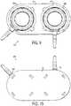
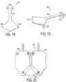
FIGS. 15-20 ,multi-port assemblies multi-port assemblies base ports bases base 106 of themulti-port assembly 100; however, thebases ports FIGS. 15-17 , theports ports FIGS. 18-20 , theports ports - The base 402 or 502 can also include one or
more port couplings ports port couplings port couplings 108 of themulti-port assembly 100, thus a detailed description thereof is omitted. In the embodiment shown, theport couplings ports ports - A split-type catheter (not shown) or a standard single lumen catheter can be used with the
multi-port assembly ports - While particular embodiments have been chosen to illustrate the invention, it will be understood by those skilled in the art that various changes and modifications can be made to these embodiments without departing from the scope of the invention as defined in the appended claims.
Claims (15)
- A multiple vascular access port assembly comprising:
a base assembly configured to receive multiple, self-contained vascular access ports, the base assembly including:a first base surface and an opposing second base surface;multiple port receiving areas on the first base surface, each port receiving area configured to receive and attach to the base assembly one self-contained vascular access port,characterized in that each port receiving area includes: multiple port couplings extending from the first base surface, and along a periphery thereof, each port coupling including an extending portion and a coupling portion, where the extending portion extends vertically from and substantially perpendicular to the first base surface and the coupling portion extends from and substantially perpendicular to the extending portion, the coupling portion extending in a direction radially inward of the port receiving area, where an inside height of each extending portion corresponds to a thickness height of a peripheral flange of a respective, self-contained vascular access port. - The port assembly of claim 1, further comprising multiple, self-contained vascular access ports configured to be received by and attached to the base assembly.
- The port assembly of claim 1, wherein each multiple port receiving area further comprises a flange extending vertically from the first base surface, and along a periphery of the multiple port receiving area, the flange configured to abut, and provide mechanical support to, an edge of the peripheral flange the respective, self-contained vascular access port.
- The port assembly of claim 3, wherein the flange extends around approximately one-third of the periphery of each port receiving area.
- The port assembly of claim 3, wherein the flange joins one or more of the port couplings.
- The port assembly of claim 1, wherein three multiple port couplings are employed, and are disposed substantially equidistant from one another along the periphery of each port receiving area.
- The port assembly of claim 1, wherein each port receiving area includes a knurled surface on the first base surface, the knurled surface configured to mate with a corresponding knurled surface on a bottom of each self-contained vascular access port, whereby the respective knurled surfaces lock in mating relationship upon attachment of a respective vascular access port to the base assembly.
- The port assembly of claim 7, wherein the first base surface is multi-tiered, so that a first port receiving area is disposed on a plane parallel to, but differing from, a plane of a second port receiving area, whereby respective vascular access ports of different heights will be disposed with tops thereof lying on a same plane, and whereby respective vascular access ports of similar heights will be disposed with tops thereof lying on a different plane.
- The port assembly of claim 8, further comprising multiple, self-contained vascular access ports, wherein each self-contained vascular access port includes a knurled surface on a bottom thereof that corresponds to the knurled surface of a respective port receiving area, whereby the respective knurled surfaces lock in mating relationship upon attachment of a respective vascular access port to the base assembly.
- The port assembly of claim 9, wherein each self-contained vascular access port further includes a peripheral flange having a thickness height corresponding to an inside height of a respective extending portion, thereby facilitating the receiving and attaching of a respective vascular access port to the base assembly.
- The port assembly of claim 7, further comprising multiple, self-contained vascular access ports, wherein each self-contained vascular access port includes a knurled surface on a bottom thereof that corresponds to the knurled surface of a respective port receiving area, whereby the respective knurled surfaces lock in mating relationship upon attachment of a respective vascular access port to the base assembly.
- The port assembly of claim 11, wherein each self-contained vascular access port further includes a peripheral flange having a thickness height corresponding to an inside height of a respective extending portion, thereby facilitating the receiving and attaching of a respective vascular access port to the base assembly.
- The port assembly of claim 12 wherein the coupling portion of at least one port coupling of each multiple port receiving area is configured to receive a peg perpendicularly therethrough to engage a top surface of the peripheral flange of a respective, self-contained vascular access port, thereby providing mechanical support to the attachment of a respective vascular access port to the base assembly.
- The port assembly of claim 1, wherein the coupling portion of at least one port coupling of each multiple port receiving area is configured to receive a peg perpendicularly therethrough to engage a top surface of the peripheral flange of a respective, self-contained vascular access port, thereby providing mechanical support to the attachment of a respective vascular access port to the base assembly.
- The port assembly of claim 1, wherein the first base surface is multi-tiered, so that a first port receiving area is disposed on a plane parallel to, but differing from, a plane of a second port receiving area, whereby respective vascular access ports of different heights will be disposed with tops thereof lying on a same plane, and whereby respective vascular access ports of similar heights will be disposed with tops thereof lying on a different plane.
Applications Claiming Priority (2)
| Application Number | Priority Date | Filing Date | Title |
|---|---|---|---|
| US25514809P | 2009-10-27 | 2009-10-27 | |
| PCT/US2010/053462WO2011053499A1 (en) | 2009-10-27 | 2010-10-21 | Multi-port assembly |
Publications (3)
| Publication Number | Publication Date |
|---|---|
| EP2493527A1 EP2493527A1 (en) | 2012-09-05 |
| EP2493527A4 EP2493527A4 (en) | 2017-09-13 |
| EP2493527B1true EP2493527B1 (en) | 2018-12-19 |
Family
ID=43899033
Family Applications (1)
| Application Number | Title | Priority Date | Filing Date |
|---|---|---|---|
| EP10827336.8ANot-in-forceEP2493527B1 (en) | 2009-10-27 | 2010-10-21 | Multiple vascular access port assembly |
Country Status (6)
| Country | Link |
|---|---|
| US (1) | US8591483B2 (en) |
| EP (1) | EP2493527B1 (en) |
| CA (1) | CA2779068C (en) |
| ES (1) | ES2715185T3 (en) |
| MX (1) | MX2012005113A (en) |
| WO (1) | WO2011053499A1 (en) |
Families Citing this family (22)
| Publication number | Priority date | Publication date | Assignee | Title |
|---|---|---|---|---|
| US8177762B2 (en) | 1998-12-07 | 2012-05-15 | C. R. Bard, Inc. | Septum including at least one identifiable feature, access ports including same, and related methods |
| US9474888B2 (en) | 2005-03-04 | 2016-10-25 | C. R. Bard, Inc. | Implantable access port including a sandwiched radiopaque insert |
| US8029482B2 (en) | 2005-03-04 | 2011-10-04 | C. R. Bard, Inc. | Systems and methods for radiographically identifying an access port |
| US7947022B2 (en) | 2005-03-04 | 2011-05-24 | C. R. Bard, Inc. | Access port identification systems and methods |
| JP5484674B2 (en) | 2005-03-04 | 2014-05-07 | シー・アール・バード・インコーポレーテッド | Access port and identification method |
| US10307581B2 (en) | 2005-04-27 | 2019-06-04 | C. R. Bard, Inc. | Reinforced septum for an implantable medical device |
| EP1874393B1 (en) | 2005-04-27 | 2017-09-06 | C.R.Bard, Inc. | Infusion apparatuses |
| EP3884989B1 (en) | 2005-04-27 | 2022-07-13 | C. R. Bard, Inc. | Vascular access port |
| US9265912B2 (en) | 2006-11-08 | 2016-02-23 | C. R. Bard, Inc. | Indicia informative of characteristics of insertable medical devices |
| US9642986B2 (en) | 2006-11-08 | 2017-05-09 | C. R. Bard, Inc. | Resource information key for an insertable medical device |
| US9579496B2 (en) | 2007-11-07 | 2017-02-28 | C. R. Bard, Inc. | Radiopaque and septum-based indicators for a multi-lumen implantable port |
| US8932271B2 (en) | 2008-11-13 | 2015-01-13 | C. R. Bard, Inc. | Implantable medical devices including septum-based indicators |
| US11890443B2 (en) | 2008-11-13 | 2024-02-06 | C. R. Bard, Inc. | Implantable medical devices including septum-based indicators |
| ES2695907T3 (en) | 2009-11-17 | 2019-01-11 | Bard Inc C R | Overmolded access port that includes anchoring and identification features |
| USD676955S1 (en) | 2010-12-30 | 2013-02-26 | C. R. Bard, Inc. | Implantable access port |
| USD682416S1 (en) | 2010-12-30 | 2013-05-14 | C. R. Bard, Inc. | Implantable access port |
| US9707339B2 (en) | 2012-03-28 | 2017-07-18 | Angiodynamics, Inc. | High flow rate dual reservoir port system |
| US9713704B2 (en) | 2012-03-29 | 2017-07-25 | Bradley D. Chartrand | Port reservoir cleaning system and method |
| WO2013146307A1 (en)* | 2012-03-29 | 2013-10-03 | テルモ・クリニカルサプライ株式会社 | Device for injecting drug solution into body |
| US11013858B2 (en)* | 2016-01-12 | 2021-05-25 | David S. Goldsmith | Nonjacketing side-entry connectors and prosthetic disorder response systems |
| US10166321B2 (en) | 2014-01-09 | 2019-01-01 | Angiodynamics, Inc. | High-flow port and infusion needle systems |
| WO2024050005A2 (en)* | 2022-09-01 | 2024-03-07 | Icahn School Of Medicine At Mount Sinai | Implantable access port device for localized treatments and measurements, and method of using same |
Family Cites Families (17)
| Publication number | Priority date | Publication date | Assignee | Title |
|---|---|---|---|---|
| US4170082A (en)* | 1977-02-28 | 1979-10-09 | Calvin Freedman | Modular connectors for cylindrical elements |
| US4692146A (en)* | 1985-10-24 | 1987-09-08 | Cormed, Inc. | Multiple vascular access port |
| US5360407A (en)* | 1991-08-29 | 1994-11-01 | C. R. Bard, Inc. | Implantable dual access port with tactile ridge for position sensing |
| US5387192A (en)* | 1994-01-24 | 1995-02-07 | Sims Deltec, Inc. | Hybrid portal and method |
| US5445616A (en)* | 1994-04-29 | 1995-08-29 | Medtronic, Inc. | Medication delivery device and method of construction |
| US5433314A (en)* | 1994-07-05 | 1995-07-18 | Lin; Lien-Sheng | Separable receptacle for receiving contact lenses |
| US5718682A (en)* | 1996-06-28 | 1998-02-17 | United States Surgical Corporation | Access port device and method of manufacture |
| US6086555A (en)* | 1997-01-17 | 2000-07-11 | C. R. Bard, Inc. | Dual reservoir vascular access port with two-piece housing and compound septum |
| US8343115B2 (en)* | 2001-01-05 | 2013-01-01 | Applied Diabetes Research, Inc. | Low profile pivoting joint infusion assembly |
| WO2004032991A2 (en)* | 2002-10-09 | 2004-04-22 | Edrich Vascular Devices, Inc. | Implantable dialysis access port |
| US8574204B2 (en)* | 2002-10-21 | 2013-11-05 | Angiodynamics, Inc. | Implantable medical device for improved placement and adherence in the body |
| US20040199129A1 (en)* | 2003-04-07 | 2004-10-07 | Scimed Life Systems, Inc. | Vascular access port |
| US7901381B2 (en)* | 2003-09-15 | 2011-03-08 | Allergan, Inc. | Implantable device fastening system and methods of use |
| US8267915B2 (en)* | 2004-01-29 | 2012-09-18 | Navilyst Medical, Inc. | Dual well port device |
| WO2006014947A2 (en)* | 2004-07-26 | 2006-02-09 | C.R. Bard, Inc. | Port design and method of assembly |
| US7794422B2 (en)* | 2005-05-27 | 2010-09-14 | Medical Components, Inc. | Catheter port assembly for extracorporeal treatment |
| CA2701644A1 (en)* | 2007-10-05 | 2009-04-09 | Angiodynamics, Inc. | Dual reservoir implantable access port |
- 2010
- 2010-10-21MXMX2012005113Apatent/MX2012005113A/enactiveIP Right Grant
- 2010-10-21EPEP10827336.8Apatent/EP2493527B1/ennot_activeNot-in-force
- 2010-10-21WOPCT/US2010/053462patent/WO2011053499A1/enactiveApplication Filing
- 2010-10-21USUS12/908,925patent/US8591483B2/enactiveActive
- 2010-10-21ESES10827336Tpatent/ES2715185T3/enactiveActive
- 2010-10-21CACA2779068Apatent/CA2779068C/enactiveActive
Non-Patent Citations (1)
| Title |
|---|
| None* |
Also Published As
| Publication number | Publication date |
|---|---|
| US8591483B2 (en) | 2013-11-26 |
| MX2012005113A (en) | 2012-08-03 |
| EP2493527A1 (en) | 2012-09-05 |
| WO2011053499A1 (en) | 2011-05-05 |
| EP2493527A4 (en) | 2017-09-13 |
| CA2779068A1 (en) | 2011-05-05 |
| ES2715185T3 (en) | 2019-06-03 |
| US20110098662A1 (en) | 2011-04-28 |
| CA2779068C (en) | 2017-05-02 |
Similar Documents
| Publication | Publication Date | Title |
|---|---|---|
| EP2493527B1 (en) | Multiple vascular access port assembly | |
| EP0792658B1 (en) | Catheter with improved tape down wing | |
| AU2019201867B2 (en) | Transfer device valve | |
| US9168359B2 (en) | Modular introducer and exchange sheath | |
| US8529525B2 (en) | Implantable vascular access system | |
| EP0792662B1 (en) | Barbed luer adapter | |
| US4929236A (en) | Snap-lock fitting catheter for an implantable device | |
| US8267915B2 (en) | Dual well port device | |
| EP2603253B1 (en) | Collet lock | |
| JPH05200107A (en) | Embedding mold access port | |
| EP2574365A1 (en) | Hemodialysis catheter with improved side opening design | |
| US20140018772A1 (en) | Self-centering catheter with anti-occlusion features | |
| US9072867B2 (en) | Catheter with external flow channel | |
| CN114007684A (en) | Implantable vascular access port with dual and needle locks for high flow | |
| US20240382735A1 (en) | Implantable vascular access port with dual, high-flow trans-chamber and low-flow, access, and needle lock for high-flow | |
| US20200016390A1 (en) | Vascular access port and catheter | |
| EP0792655A2 (en) | Catheter with improved extension tube |
Legal Events
| Date | Code | Title | Description |
|---|---|---|---|
| PUAI | Public reference made under article 153(3) epc to a published international application that has entered the european phase | Free format text:ORIGINAL CODE: 0009012 | |
| 17P | Request for examination filed | Effective date:20120525 | |
| AK | Designated contracting states | Kind code of ref document:A1 Designated state(s):AL AT BE BG CH CY CZ DE DK EE ES FI FR GB GR HR HU IE IS IT LI LT LU LV MC MK MT NL NO PL PT RO RS SE SI SK SM TR | |
| DAX | Request for extension of the european patent (deleted) | ||
| REG | Reference to a national code | Ref country code:DE Ref legal event code:R079 Ref document number:602010055977 Country of ref document:DE Free format text:PREVIOUS MAIN CLASS: A61M0005000000 Ipc:A61M0039020000 | |
| RA4 | Supplementary search report drawn up and despatched (corrected) | Effective date:20170810 | |
| RIC1 | Information provided on ipc code assigned before grant | Ipc:A61M 39/02 20060101AFI20170804BHEP | |
| GRAJ | Information related to disapproval of communication of intention to grant by the applicant or resumption of examination proceedings by the epo deleted | Free format text:ORIGINAL CODE: EPIDOSDIGR1 | |
| GRAP | Despatch of communication of intention to grant a patent | Free format text:ORIGINAL CODE: EPIDOSNIGR1 | |
| STAA | Information on the status of an ep patent application or granted ep patent | Free format text:STATUS: REQUEST FOR EXAMINATION WAS MADE | |
| GRAP | Despatch of communication of intention to grant a patent | Free format text:ORIGINAL CODE: EPIDOSNIGR1 | |
| STAA | Information on the status of an ep patent application or granted ep patent | Free format text:STATUS: GRANT OF PATENT IS INTENDED | |
| INTG | Intention to grant announced | Effective date:20180626 | |
| GRAS | Grant fee paid | Free format text:ORIGINAL CODE: EPIDOSNIGR3 | |
| GRAA | (expected) grant | Free format text:ORIGINAL CODE: 0009210 | |
| STAA | Information on the status of an ep patent application or granted ep patent | Free format text:STATUS: THE PATENT HAS BEEN GRANTED | |
| AK | Designated contracting states | Kind code of ref document:B1 Designated state(s):AL AT BE BG CH CY CZ DE DK EE ES FI FR GB GR HR HU IE IS IT LI LT LU LV MC MK MT NL NO PL PT RO RS SE SI SK SM TR | |
| REG | Reference to a national code | Ref country code:GB Ref legal event code:FG4D | |
| REG | Reference to a national code | Ref country code:CH Ref legal event code:EP | |
| REG | Reference to a national code | Ref country code:IE Ref legal event code:FG4D | |
| REG | Reference to a national code | Ref country code:DE Ref legal event code:R096 Ref document number:602010055977 Country of ref document:DE | |
| REG | Reference to a national code | Ref country code:AT Ref legal event code:REF Ref document number:1078015 Country of ref document:AT Kind code of ref document:T Effective date:20190115 | |
| REG | Reference to a national code | Ref country code:NL Ref legal event code:MP Effective date:20181219 | |
| PG25 | Lapsed in a contracting state [announced via postgrant information from national office to epo] | Ref country code:NO Free format text:LAPSE BECAUSE OF FAILURE TO SUBMIT A TRANSLATION OF THE DESCRIPTION OR TO PAY THE FEE WITHIN THE PRESCRIBED TIME-LIMIT Effective date:20190319 Ref country code:LT Free format text:LAPSE BECAUSE OF FAILURE TO SUBMIT A TRANSLATION OF THE DESCRIPTION OR TO PAY THE FEE WITHIN THE PRESCRIBED TIME-LIMIT Effective date:20181219 Ref country code:FI Free format text:LAPSE BECAUSE OF FAILURE TO SUBMIT A TRANSLATION OF THE DESCRIPTION OR TO PAY THE FEE WITHIN THE PRESCRIBED TIME-LIMIT Effective date:20181219 Ref country code:LV Free format text:LAPSE BECAUSE OF FAILURE TO SUBMIT A TRANSLATION OF THE DESCRIPTION OR TO PAY THE FEE WITHIN THE PRESCRIBED TIME-LIMIT Effective date:20181219 Ref country code:HR Free format text:LAPSE BECAUSE OF FAILURE TO SUBMIT A TRANSLATION OF THE DESCRIPTION OR TO PAY THE FEE WITHIN THE PRESCRIBED TIME-LIMIT Effective date:20181219 Ref country code:BG Free format text:LAPSE BECAUSE OF FAILURE TO SUBMIT A TRANSLATION OF THE DESCRIPTION OR TO PAY THE FEE WITHIN THE PRESCRIBED TIME-LIMIT Effective date:20190319 | |
| REG | Reference to a national code | Ref country code:LT Ref legal event code:MG4D | |
| REG | Reference to a national code | Ref country code:AT Ref legal event code:MK05 Ref document number:1078015 Country of ref document:AT Kind code of ref document:T Effective date:20181219 | |
| PG25 | Lapsed in a contracting state [announced via postgrant information from national office to epo] | Ref country code:GR Free format text:LAPSE BECAUSE OF FAILURE TO SUBMIT A TRANSLATION OF THE DESCRIPTION OR TO PAY THE FEE WITHIN THE PRESCRIBED TIME-LIMIT Effective date:20190320 Ref country code:AL Free format text:LAPSE BECAUSE OF FAILURE TO SUBMIT A TRANSLATION OF THE DESCRIPTION OR TO PAY THE FEE WITHIN THE PRESCRIBED TIME-LIMIT Effective date:20181219 Ref country code:SE Free format text:LAPSE BECAUSE OF FAILURE TO SUBMIT A TRANSLATION OF THE DESCRIPTION OR TO PAY THE FEE WITHIN THE PRESCRIBED TIME-LIMIT Effective date:20181219 Ref country code:RS Free format text:LAPSE BECAUSE OF FAILURE TO SUBMIT A TRANSLATION OF THE DESCRIPTION OR TO PAY THE FEE WITHIN THE PRESCRIBED TIME-LIMIT Effective date:20181219 | |
| REG | Reference to a national code | Ref country code:ES Ref legal event code:FG2A Ref document number:2715185 Country of ref document:ES Kind code of ref document:T3 Effective date:20190603 | |
| PG25 | Lapsed in a contracting state [announced via postgrant information from national office to epo] | Ref country code:NL Free format text:LAPSE BECAUSE OF FAILURE TO SUBMIT A TRANSLATION OF THE DESCRIPTION OR TO PAY THE FEE WITHIN THE PRESCRIBED TIME-LIMIT Effective date:20181219 | |
| PG25 | Lapsed in a contracting state [announced via postgrant information from national office to epo] | Ref country code:PL Free format text:LAPSE BECAUSE OF FAILURE TO SUBMIT A TRANSLATION OF THE DESCRIPTION OR TO PAY THE FEE WITHIN THE PRESCRIBED TIME-LIMIT Effective date:20181219 Ref country code:PT Free format text:LAPSE BECAUSE OF FAILURE TO SUBMIT A TRANSLATION OF THE DESCRIPTION OR TO PAY THE FEE WITHIN THE PRESCRIBED TIME-LIMIT Effective date:20190419 Ref country code:CZ Free format text:LAPSE BECAUSE OF FAILURE TO SUBMIT A TRANSLATION OF THE DESCRIPTION OR TO PAY THE FEE WITHIN THE PRESCRIBED TIME-LIMIT Effective date:20181219 Ref country code:IT Free format text:LAPSE BECAUSE OF FAILURE TO SUBMIT A TRANSLATION OF THE DESCRIPTION OR TO PAY THE FEE WITHIN THE PRESCRIBED TIME-LIMIT Effective date:20181219 | |
| PG25 | Lapsed in a contracting state [announced via postgrant information from national office to epo] | Ref country code:EE Free format text:LAPSE BECAUSE OF FAILURE TO SUBMIT A TRANSLATION OF THE DESCRIPTION OR TO PAY THE FEE WITHIN THE PRESCRIBED TIME-LIMIT Effective date:20181219 Ref country code:SM Free format text:LAPSE BECAUSE OF FAILURE TO SUBMIT A TRANSLATION OF THE DESCRIPTION OR TO PAY THE FEE WITHIN THE PRESCRIBED TIME-LIMIT Effective date:20181219 Ref country code:SK Free format text:LAPSE BECAUSE OF FAILURE TO SUBMIT A TRANSLATION OF THE DESCRIPTION OR TO PAY THE FEE WITHIN THE PRESCRIBED TIME-LIMIT Effective date:20181219 Ref country code:RO Free format text:LAPSE BECAUSE OF FAILURE TO SUBMIT A TRANSLATION OF THE DESCRIPTION OR TO PAY THE FEE WITHIN THE PRESCRIBED TIME-LIMIT Effective date:20181219 Ref country code:IS Free format text:LAPSE BECAUSE OF FAILURE TO SUBMIT A TRANSLATION OF THE DESCRIPTION OR TO PAY THE FEE WITHIN THE PRESCRIBED TIME-LIMIT Effective date:20190419 | |
| REG | Reference to a national code | Ref country code:DE Ref legal event code:R097 Ref document number:602010055977 Country of ref document:DE | |
| PLBE | No opposition filed within time limit | Free format text:ORIGINAL CODE: 0009261 | |
| STAA | Information on the status of an ep patent application or granted ep patent | Free format text:STATUS: NO OPPOSITION FILED WITHIN TIME LIMIT | |
| PG25 | Lapsed in a contracting state [announced via postgrant information from national office to epo] | Ref country code:DK Free format text:LAPSE BECAUSE OF FAILURE TO SUBMIT A TRANSLATION OF THE DESCRIPTION OR TO PAY THE FEE WITHIN THE PRESCRIBED TIME-LIMIT Effective date:20181219 Ref country code:AT Free format text:LAPSE BECAUSE OF FAILURE TO SUBMIT A TRANSLATION OF THE DESCRIPTION OR TO PAY THE FEE WITHIN THE PRESCRIBED TIME-LIMIT Effective date:20181219 | |
| 26N | No opposition filed | Effective date:20190920 | |
| PG25 | Lapsed in a contracting state [announced via postgrant information from national office to epo] | Ref country code:SI Free format text:LAPSE BECAUSE OF FAILURE TO SUBMIT A TRANSLATION OF THE DESCRIPTION OR TO PAY THE FEE WITHIN THE PRESCRIBED TIME-LIMIT Effective date:20181219 | |
| PG25 | Lapsed in a contracting state [announced via postgrant information from national office to epo] | Ref country code:TR Free format text:LAPSE BECAUSE OF FAILURE TO SUBMIT A TRANSLATION OF THE DESCRIPTION OR TO PAY THE FEE WITHIN THE PRESCRIBED TIME-LIMIT Effective date:20181219 | |
| PG25 | Lapsed in a contracting state [announced via postgrant information from national office to epo] | Ref country code:MC Free format text:LAPSE BECAUSE OF FAILURE TO SUBMIT A TRANSLATION OF THE DESCRIPTION OR TO PAY THE FEE WITHIN THE PRESCRIBED TIME-LIMIT Effective date:20181219 | |
| REG | Reference to a national code | Ref country code:CH Ref legal event code:PL | |
| PG25 | Lapsed in a contracting state [announced via postgrant information from national office to epo] | Ref country code:LU Free format text:LAPSE BECAUSE OF NON-PAYMENT OF DUE FEES Effective date:20191021 Ref country code:LI Free format text:LAPSE BECAUSE OF NON-PAYMENT OF DUE FEES Effective date:20191031 Ref country code:CH Free format text:LAPSE BECAUSE OF NON-PAYMENT OF DUE FEES Effective date:20191031 | |
| REG | Reference to a national code | Ref country code:BE Ref legal event code:MM Effective date:20191031 | |
| PG25 | Lapsed in a contracting state [announced via postgrant information from national office to epo] | Ref country code:BE Free format text:LAPSE BECAUSE OF NON-PAYMENT OF DUE FEES Effective date:20191031 | |
| PG25 | Lapsed in a contracting state [announced via postgrant information from national office to epo] | Ref country code:IE Free format text:LAPSE BECAUSE OF NON-PAYMENT OF DUE FEES Effective date:20191021 | |
| PG25 | Lapsed in a contracting state [announced via postgrant information from national office to epo] | Ref country code:CY Free format text:LAPSE BECAUSE OF FAILURE TO SUBMIT A TRANSLATION OF THE DESCRIPTION OR TO PAY THE FEE WITHIN THE PRESCRIBED TIME-LIMIT Effective date:20181219 | |
| PG25 | Lapsed in a contracting state [announced via postgrant information from national office to epo] | Ref country code:MT Free format text:LAPSE BECAUSE OF FAILURE TO SUBMIT A TRANSLATION OF THE DESCRIPTION OR TO PAY THE FEE WITHIN THE PRESCRIBED TIME-LIMIT Effective date:20181219 Ref country code:HU Free format text:LAPSE BECAUSE OF FAILURE TO SUBMIT A TRANSLATION OF THE DESCRIPTION OR TO PAY THE FEE WITHIN THE PRESCRIBED TIME-LIMIT; INVALID AB INITIO Effective date:20101021 | |
| PG25 | Lapsed in a contracting state [announced via postgrant information from national office to epo] | Ref country code:MK Free format text:LAPSE BECAUSE OF FAILURE TO SUBMIT A TRANSLATION OF THE DESCRIPTION OR TO PAY THE FEE WITHIN THE PRESCRIBED TIME-LIMIT Effective date:20181219 | |
| PGFP | Annual fee paid to national office [announced via postgrant information from national office to epo] | Ref country code:GB Payment date:20220901 Year of fee payment:13 | |
| PGFP | Annual fee paid to national office [announced via postgrant information from national office to epo] | Ref country code:FR Payment date:20220908 Year of fee payment:13 | |
| PGFP | Annual fee paid to national office [announced via postgrant information from national office to epo] | Ref country code:ES Payment date:20221104 Year of fee payment:13 Ref country code:DE Payment date:20220831 Year of fee payment:13 | |
| P01 | Opt-out of the competence of the unified patent court (upc) registered | Effective date:20230420 | |
| REG | Reference to a national code | Ref country code:DE Ref legal event code:R119 Ref document number:602010055977 Country of ref document:DE | |
| GBPC | Gb: european patent ceased through non-payment of renewal fee | Effective date:20231021 | |
| PG25 | Lapsed in a contracting state [announced via postgrant information from national office to epo] | Ref country code:GB Free format text:LAPSE BECAUSE OF NON-PAYMENT OF DUE FEES Effective date:20231021 | |
| PG25 | Lapsed in a contracting state [announced via postgrant information from national office to epo] | Ref country code:GB Free format text:LAPSE BECAUSE OF NON-PAYMENT OF DUE FEES Effective date:20231021 Ref country code:FR Free format text:LAPSE BECAUSE OF NON-PAYMENT OF DUE FEES Effective date:20231031 Ref country code:DE Free format text:LAPSE BECAUSE OF NON-PAYMENT OF DUE FEES Effective date:20240501 | |
| REG | Reference to a national code | Ref country code:ES Ref legal event code:FD2A Effective date:20241204 | |
| PG25 | Lapsed in a contracting state [announced via postgrant information from national office to epo] | Ref country code:ES Free format text:LAPSE BECAUSE OF NON-PAYMENT OF DUE FEES Effective date:20231022 | |
| PG25 | Lapsed in a contracting state [announced via postgrant information from national office to epo] | Ref country code:ES Free format text:LAPSE BECAUSE OF NON-PAYMENT OF DUE FEES Effective date:20231022 |