EP2493517B1 - Dispensers and functional operation and timing control improvements for dispensers - Google Patents
Dispensers and functional operation and timing control improvements for dispensersDownload PDFInfo
- Publication number
- EP2493517B1 EP2493517B1EP10776450.8AEP10776450AEP2493517B1EP 2493517 B1EP2493517 B1EP 2493517B1EP 10776450 AEP10776450 AEP 10776450AEP 2493517 B1EP2493517 B1EP 2493517B1
- Authority
- EP
- European Patent Office
- Prior art keywords
- activation sequence
- dispensing unit
- active mode
- procedure
- container
- Prior art date
- Legal status (The legal status is an assumption and is not a legal conclusion. Google has not performed a legal analysis and makes no representation as to the accuracy of the status listed.)
- Active
Links
- 230000004913activationEffects0.000claimsdescription47
- 238000000034methodMethods0.000claimsdescription36
- 239000000463materialSubstances0.000claimsdescription9
- 230000004044responseEffects0.000claimsdescription7
- 238000007599dischargingMethods0.000claimsdescription2
- 239000012530fluidSubstances0.000claims4
- 230000003213activating effectEffects0.000claims2
- 238000001994activationMethods0.000description34
- 239000007921spraySubstances0.000description11
- 238000009792diffusion processMethods0.000description9
- 239000000443aerosolSubstances0.000description6
- 238000001514detection methodMethods0.000description6
- 230000007704transitionEffects0.000description5
- 230000000994depressogenic effectEffects0.000description3
- 238000012986modificationMethods0.000description3
- 230000004048modificationEffects0.000description3
- 239000002304perfumeSubstances0.000description2
- 239000012080ambient airSubstances0.000description1
- -1deodorizersSubstances0.000description1
- 238000010586diagramMethods0.000description1
- 230000007613environmental effectEffects0.000description1
- 239000003205fragranceSubstances0.000description1
- 239000000077insect repellentSubstances0.000description1
- 239000002917insecticideSubstances0.000description1
- 230000003993interactionEffects0.000description1
- 239000007788liquidSubstances0.000description1
- 239000002420orchardSubstances0.000description1
- 230000035945sensitivityEffects0.000description1
- 238000005507sprayingMethods0.000description1
- 230000000007visual effectEffects0.000description1
Images


Classifications
- A—HUMAN NECESSITIES
- A61—MEDICAL OR VETERINARY SCIENCE; HYGIENE
- A61L—METHODS OR APPARATUS FOR STERILISING MATERIALS OR OBJECTS IN GENERAL; DISINFECTION, STERILISATION OR DEODORISATION OF AIR; CHEMICAL ASPECTS OF BANDAGES, DRESSINGS, ABSORBENT PADS OR SURGICAL ARTICLES; MATERIALS FOR BANDAGES, DRESSINGS, ABSORBENT PADS OR SURGICAL ARTICLES
- A61L9/00—Disinfection, sterilisation or deodorisation of air
- A61L9/14—Disinfection, sterilisation or deodorisation of air using sprayed or atomised substances including air-liquid contact processes
- B—PERFORMING OPERATIONS; TRANSPORTING
- B65—CONVEYING; PACKING; STORING; HANDLING THIN OR FILAMENTARY MATERIAL
- B65D—CONTAINERS FOR STORAGE OR TRANSPORT OF ARTICLES OR MATERIALS, e.g. BAGS, BARRELS, BOTTLES, BOXES, CANS, CARTONS, CRATES, DRUMS, JARS, TANKS, HOPPERS, FORWARDING CONTAINERS; ACCESSORIES, CLOSURES, OR FITTINGS THEREFOR; PACKAGING ELEMENTS; PACKAGES
- B65D83/00—Containers or packages with special means for dispensing contents
- B65D83/14—Containers for dispensing liquid or semi-liquid contents by internal gaseous pressure, i.e. aerosol containers comprising propellant
- B65D83/16—Actuating means
- B65D83/26—Actuating means operating automatically, e.g. periodically
- B65D83/262—Actuating means operating automatically, e.g. periodically by clockwork, motor, electric or magnetic means operating without repeated human input
Definitions
- the present disclosurerelates to dispensers for discharging volatile materials from a container and methods for operating same.
- Diffusion devices or dispensersare used to dispense volatile materials, such as perfumes, deodorizers, insecticides, insect repellants, and the like. Many such devices are passive diffusion devices that require only ambient air flow to dispense the volatile material, while other devices are active diffusion devices. Active diffusion devices are found in a variety of forms, some include fans and/or heaters to aid in the dispersal of volatile materials, others actuate a valve stem of an aerosol container to dispense a volatile material contained therein, still others utilize an ultrasonic transducer to break up a liquid volatile material into droplets that are ejected from the device, and yet others include any combination of the above or any other known type of active diffusion device. Various examples of such devices can be found in Helf et al.
- some active diffusion devicesinclude a sensor to detect motion or light in a space, wherein such devices dispense a volatile material in response to signals from the sensor.
- This documentshows a dispenser with an operating schedule, whereby when power is applied there is first of all a startup delay period, followed by a spray, followed by a sleep period.
- a startup delay periodfollowed by a spray
- a sleep periodthe device is not sensitive to motion.
- the end of the sleep periodthe device becomes motion-sensitive and sprays on detection of motion.
- a further sleep periodfollows each spray.
- the inventionprovides a method of operating a dispensing unit in accordance with claim 1 below.
- Optional features of this aspectare set out in claims 2-3 below.
- the inventionprovides a dispensing unit in accordance with claim 4 below.
- Optional feature of this aspectare set out in claim 5-7 below.
- FIG. 1illustrates a device 20 that includes a microprocessor 22, a power source 24, a motor 26, a sensor 28, one or more input devices 30 such as switches, dials, keypads, pushbuttons, etc., and a light source 32, e.g., a light emitting diode (“LED").
- the power source 24supplies power to the microprocessor 22 and to the other components, wherein the microprocessor 22 is further coupled to the other components and executes programming to control the operation thereof.
- the microprocessor 22may be an ATtinyl3V based microcontroller, such as those manufactured by Atmel Corporation, of 2325 Orchard Parkway, San Jose, CA 95131. However, it is contemplated that any type of microcontroller known to those of skill in the art may be used with the present embodiments.
- FIG. 2illustrates an embodiment of the device 20 of FIG. 1 implemented as a dispenser 40 for dispensing the contents of an aerosol container 42.
- the dispenser 40may be one of the devices described in Carpenter et al. published U.S. Patent Application US2007/0199952 .
- the dispenser 40includes a housing 44 that is adapted to receive the aerosol container 42 and batteries 46.
- the dispenser 40includes a selector switch 30a, a pushbutton 30b, and an actuator arm 52.
- the dispenser 40also includes circuitry, the microprocessor 22, the motor 26, the LED 32, and the sensor 28, which are provided within the housing 44 and shown generally in FIG. 1 .
- the microprocessor 22controls the motor 26 during a spray operation to actuate the actuator arm 52, which depresses a valve stem 54 of the aerosol container 42 to dispense the contents therefrom.
- the microprocessor 22includes programming to initiate a spray operation in response to a signal generated by the switch 30a, the pushbutton 30b, a timer, or the sensor 28.
- the timercan be implemented in the microprocessor 22 or as a separate component.
- the microprocessor 22includes programming to control the dispenser 40 in a timed automatic actuation mode, wherein the dispenser 40 performs spray operations at specified time intervals, e.g., every 30 minutes.
- the microprocessor 22is programmed to perform a spray operation in response to a signal from the sensor 28, the selector switch 30a, and/or the pushbutton 30b.
- the selector switch 30ais used to turn the dispenser 40 on and off and to select between various operating modes, which may include a timed mode, a sensing mode, a combined timed and sensing mode, and other user selectable or pre-programmed functional modes and timing sequences.
- the LED 32is energized continuously or is energized and deenergized to flash and indicate that the dispenser 40 is on and operating normally and/or to provide a warning that the dispenser 40 is about to perform a spray operation.
- the pushbutton 30bis provided for manual actuation of the aerosol container 42, wherein the pushbutton 30b may be depressed by a user to cause a spraying operation at any time, except when the dispenser 40 is off.
- the pushbutton 30ballows the user to manually override the automatic actuation of the device 40.
- the sensor 28 in the present embodimentis a photocell light sensor, which may be used to detect motion.
- any other type of motion detectormay be utilized, e.g., a passive infrared or pyroelectric motion sensor, an infrared reflective motion sensor, an ultrasonic motion sensor, or a radar or microwave radio motion sensor.
- the sensor 28can be replaced or used in combination with any other type of known sensor, e.g., a heat sensor or an odor sensor.
- the programming implemented by the microprocessor 22 to control the dispenser 40initiates at a reset/start-up block 60 when the selector switch 30a is toggled into an on position or, if the selector switch 30a is not provided, when new batteries 46 are inserted into the device 40.
- controlpasses to block 62 and a startup procedure is performed, following which control passes directly to a block 64 without any lockout period therebetween and an active mode procedure is performed, as will be described in greater detail hereinafter.
- FIG. 4illustrates programming that provides further details according to one embodiment of the startup procedure 62, wherein control begins at a block 70 to provide an indication that the dispenser 40 is on, e.g., by energizing the LED 32. Next, control passes to a delay block 72 and control pauses for a predetermined period of time, e.g., about five seconds. Following the delay block 72, control passes to a block 74 and a warning or notice is issued that an activation sequence is imminent. In the present embodiment, the warning is a flashing or flickering of the LED 32, wherein the microprocessor 22 energizes and deenergizes the LED 32 two or more times within a short period of time, e.g., within three seconds.
- the warningcan be any combination of a visual, audible, tactile, olfactory, or any other warning that would be apparent to one of ordinary skill in the art.
- the programmingperforms an activation sequence.
- the activation sequenceis a spray operation that includes blocks 76, 78, and 80. More specifically, the spray operation begins at the block 76 where the motor 26 is energized to move the actuator arm 52 downwardly to depress the valve stem 54 of the aerosol container 42 into an open position. The motor 26 is deenergized in block 78. Thereafter, the motor 26 is energized to move the actuator arm 52 in the opposite direction in block 80 to assist the valve stem 54 in moving to a closed and non-depressed position.
- the motor 26is energized during the block 76 for about 1 second, the motor 26 is deenergized during the block 78 for about 150 milliseconds, and the motor 26 is energized during the block 80 for about 400 milliseconds.
- Modifications to the activation sequence of the present embodimentcan include any sequence of the same or different steps, as would be apparent to one of ordinary skill in the art.
- a relatively short delay of about five seconds or lessis provided before the activation warning and the activation sequence are performed.
- the short delayallows a user to quickly determine that the dispenser 40 is functioning properly, e.g., that all of the components are properly coupled together and functioning and that the contents of the container 42 are not depleted. Consequently, an improved user interaction with the dispenser 40 can be provided over other dispensers that require a user to wait for a longer period before being able to confirm the proper functioning of the dispenser.
- FIG. 5illustrates an embodiment of programming executed during the active mode procedure 64.
- the dispenser 40turns on the LED 32 to provide an indication that the dispenser 40 is in the active mode.
- controlpasses to a decision block 92 and the programming activates the sensor 28 to determine if motion is detected. If motion is not detected, control passes back to the block 90 and subsequently proceeds again to the block 92. However, if motion is detected, control passes to a block 94 to perform an activation sequence, which may be the same or different from the activation sequence described above in relation to FIG. 4 . After the activation sequence is performed, control passes to a block 96 to perform a user selectable or pre-programmed transition procedure before control loops back to the block 90.
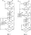
- FIGS. 6-8provide details of the transition procedure of the block 96 of FIG. 5 .
- the transition procedureincludes blocks 100 and 102, which provides for a lockout mode, wherein the sensor 28 is deactivated and the dispenser does not perform an activation sequence in response to the detection of motion. However, an activation sequence may still be performed if the pushbutton 30b is depressed.
- the decision block 102determines if the time elapsed during the lockout mode has reached a certain lockout period X. If the lockout period X has elapsed, then control passes back to the blocks 90-94 to determine if an activation sequence should be performed in response to motion.
- lockout period XIf the lockout period X has not elapsed, then control loops back to the lockout mode of the block 100.
- a usercan use an input device such as the switch 30a to select the length of the lockout period X.
- the usercan select different lockout periods ranging from 5 min, 20 min, 30 min, 60 min, etc. for different sized rooms or user preferences.
- the lockout periodmay be a pre-programmed period.
- the transition procedureincludes blocks 110-116. More specifically, at a block 110 the control implements a lockout mode as described above. However, in the present embodiment, the control performs one or more automatic activation sequences during the lockout period. For example, the decision block 112 determines if the elapsed time during the lockout mode is equal to a time X and, if so, control passes to a block 114 to perform an activation sequence. After the block 114, control passes back to the block 110 and subsequently to the block 112. If the block 112 determines that the elapsed time is not equal to X, control passes to the block 116, which determines if the elapsed time is equal to Y, which in the present embodiment represents the total lockout period.
- the usercan use an input device such as the switch 30a to select the length of the total lockout period, the number of automatic activation sequences during the lockout period, and the times at which the automatic activation sequence(s) are performed. In one example, the user selects a 30 min lockout period and a single automatic activation sequence at 15 min into the lockout period. In another example, the user selects a 60 min lockout period and a first automatic activation sequence at 20 min and a second automatic activation sequence at 40 min into the lockout period.
- the userselects a 40 min lockout period and a single activation sequence at 10 min into the lockout period.
- one or more of the total lockout periods, the number of automatic activation sequences, and the times at which the automatic activation sequences are performedmay be pre-programmed.
- the transition procedureincludes blocks 130-138. More specifically, at the block 92 if motion is not detected, then control passes back to the block 90, as discussed above. However, if motion is detected at the block 92, then control passes to a block 130, which determines how many times that motion has been detected and an activation or spray sequence performed. If motion has been detected and an activation sequence performed X times, then control passes to the block 132 and another activation sequence is performed before control passes to a lockout mode of the block 136 and the decision block 138. The decision block 138 determines if the lockout period has expired, as described above.
- controldoes not execute a lockout mode until a second or subsequent motion detection/activation sequence is performed.
- the usercan use an input device such as the switch 30a to select the number of motion detection/activation sequences that are to be performed before entering the lockout mode. For example, the user can set the switch 30a so that control executes the lockout mode only after a second, third, fourth, etc. motion detection/activation sequence is performed. In other embodiments, the number of motion detection/activation sequences that are to be performed before entering the lockout mode is preprogrammed.
- the programmingperforms the active mode after the startup procedure without any lockout period therebetween, which allows the user to execute the sensor based operation of the active mode without waiting for a lockout period to expire. Consequently, a user can confirm the proper operation of the sensor quickly upon startup of the dispenser. For example, after the startup procedure is performed, the user can immediately test the sensor by waving their hand in front of the sensor to trigger an activation sequence. Further, the user can immediately test the sensitivity of the sensor by waving their hand at different distances from the sensor and/or at different speeds/amplitudes. As a result, the user can quickly and conveniently determine a preferred placement of the dispenser in a room.
- the usercan use the switch 30a to adjust the number of activation sequences that are performed each time motion is sensed, e.g., between one, two, or three activations each time motion is detected.
- the usercan use the switch 30a to adjust a lockout period between the startup procedure and the active mode between zero and twenty minutes, for example.
- the dispenser described hereinadvantageously allows for the contents of a container to be sprayed into the atmosphere in a manner that can be adjusted by a user to accommodate different room conditions, environmental conditions, and personal preferences.
Landscapes
- Health & Medical Sciences (AREA)
- Epidemiology (AREA)
- Life Sciences & Earth Sciences (AREA)
- Animal Behavior & Ethology (AREA)
- General Health & Medical Sciences (AREA)
- Public Health (AREA)
- Veterinary Medicine (AREA)
- Chemical & Material Sciences (AREA)
- Dispersion Chemistry (AREA)
- Engineering & Computer Science (AREA)
- Mechanical Engineering (AREA)
- Containers And Packaging Bodies Having A Special Means To Remove Contents (AREA)
- Nozzles (AREA)
- Catching Or Destruction (AREA)
Description
- The present disclosure relates to dispensers for discharging volatile materials from a container and methods for operating same.
- Diffusion devices or dispensers are used to dispense volatile materials, such as perfumes, deodorizers, insecticides, insect repellants, and the like. Many such devices are passive diffusion devices that require only ambient air flow to dispense the volatile material, while other devices are active diffusion devices. Active diffusion devices are found in a variety of forms, some include fans and/or heaters to aid in the dispersal of volatile materials, others actuate a valve stem of an aerosol container to dispense a volatile material contained therein, still others utilize an ultrasonic transducer to break up a liquid volatile material into droplets that are ejected from the device, and yet others include any combination of the above or any other known type of active diffusion device. Various examples of such devices can be found in Helf et al. published U.S. Patent application
US 2007/0235555 , Beland et al. published U.S. Patent applicationUS 2008 / 0277411 , Helf et al. published U.S. Patent applicationUS 2009 / 0045218 , Helf et al. published U.S. Patent applicationUS 2009/0045219 , Helf et al. published U.S. Patent applicationUS 2009/0045220 , Helf et al. published U.S. Patent applicationUS 2008/0290120 , Sipinski et al. published U.S. Patent applicationUS 2009/0254770 , Sipinski et al. published U.S. Patent applicationUS 2009 / 0309717 ,Pedrotti et al. U.S. Patent No. 6,917,754 , and SchwarzU.S. Patent No. 7,540,473 . Further, some active diffusion devices include a sensor to detect motion or light in a space, wherein such devices dispense a volatile material in response to signals from the sensor. - Early diffusion devices that included sensors were developed to operate according to predefined operating methodologies for use in such places as restrooms to dispense perfumes or deodorizers to combat malodors. However, when a need arose for diffusion devices to be used in other environments, e.g., a living room, an office space, a factory floor, an outdoor area, etc., prior art devices that were developed for use in restrooms were found to lack the versatility necessary to be utilized in new environments. Consequently, a need has arisen for dispensers to provide an improved user experience and to enable a user to control the diffusion of a fragrance in different environments. The present disclosure relates to solutions to address such needs. An example of a known dispenser is shown in
US 2007/0199952 . This document shows a dispenser with an operating schedule, whereby when power is applied there is first of all a startup delay period, followed by a spray, followed by a sleep period. During the sleep period the device is not sensitive to motion. After the end of the sleep period the device becomes motion-sensitive and sprays on detection of motion. A further sleep period follows each spray. - In a first aspect the invention provides a method of operating a dispensing unit in accordance with claim 1 below. Optional features of this aspect are set out in claims 2-3 below. In a second aspect the invention provides a dispensing unit in accordance with claim 4 below. Optional feature of this aspect are set out in claim 5-7 below.
FIG. 1 is a block diagram of one embodiment of a dispenser;FIG. 2 is an isometric view of a dispenser according to another embodiment;FIG. 3 is a flowchart that illustrates programming that may be executed by the dispensers ofFIGS. 1 and/or 2;FIG. 4 is a flowchart that illustrates another embodiment of the programming ofFIG. 3 , including further details of a startup procedure;FIG. 5 is a flowchart that illustrates programming that may be executed during an active mode procedure of the dispensers ofFIGS. 1 and/or 2;FIG. 6 is a flowchart that illustrates another embodiment of the active mode procedure ofFIG. 5 ;FIG. 7 is a flowchart that illustrates a further embodiment of the active mode procedure ofFIG. 5 ; andFIG. 8 is a flowchart that illustrates yet another embodiment of the active mode procedure ofFIG. 5 .FIG. 1 illustrates adevice 20 that includes amicroprocessor 22, apower source 24, amotor 26, asensor 28, one ormore input devices 30 such as switches, dials, keypads, pushbuttons, etc., and alight source 32, e.g., a light emitting diode ("LED"). Thepower source 24 supplies power to themicroprocessor 22 and to the other components, wherein themicroprocessor 22 is further coupled to the other components and executes programming to control the operation thereof. In one embodiment, themicroprocessor 22 may be an ATtinyl3V based microcontroller, such as those manufactured by Atmel Corporation, of 2325 Orchard Parkway, San Jose, CA 95131. However, it is contemplated that any type of microcontroller known to those of skill in the art may be used with the present embodiments.FIG. 2 illustrates an embodiment of thedevice 20 ofFIG. 1 implemented as adispenser 40 for dispensing the contents of anaerosol container 42. Thedispenser 40 may be one of the devices described in Carpenter et al. published U.S. Patent ApplicationUS2007/0199952 . Thedispenser 40 includes ahousing 44 that is adapted to receive theaerosol container 42 andbatteries 46. In addition, thedispenser 40 includes aselector switch 30a, apushbutton 30b, and anactuator arm 52. Thedispenser 40 also includes circuitry, themicroprocessor 22, themotor 26, theLED 32, and thesensor 28, which are provided within thehousing 44 and shown generally inFIG. 1 .- The
microprocessor 22 controls themotor 26 during a spray operation to actuate theactuator arm 52, which depresses avalve stem 54 of theaerosol container 42 to dispense the contents therefrom. Themicroprocessor 22 includes programming to initiate a spray operation in response to a signal generated by theswitch 30a, thepushbutton 30b, a timer, or thesensor 28. The timer can be implemented in themicroprocessor 22 or as a separate component. For example, in one embodiment, themicroprocessor 22 includes programming to control thedispenser 40 in a timed automatic actuation mode, wherein thedispenser 40 performs spray operations at specified time intervals, e.g., every 30 minutes. Alternatively, or in conjunction with the previous embodiment, themicroprocessor 22 is programmed to perform a spray operation in response to a signal from thesensor 28, theselector switch 30a, and/or thepushbutton 30b. - For purposes of illustration only, one particular embodiment of the operation of the
dispenser 40 will be described with particularity. Turning again toFIG. 2 , in the present embodiment theselector switch 30a is used to turn thedispenser 40 on and off and to select between various operating modes, which may include a timed mode, a sensing mode, a combined timed and sensing mode, and other user selectable or pre-programmed functional modes and timing sequences. TheLED 32 is energized continuously or is energized and deenergized to flash and indicate that thedispenser 40 is on and operating normally and/or to provide a warning that thedispenser 40 is about to perform a spray operation. Thepushbutton 30b is provided for manual actuation of theaerosol container 42, wherein thepushbutton 30b may be depressed by a user to cause a spraying operation at any time, except when thedispenser 40 is off. The pushbutton 30b allows the user to manually override the automatic actuation of thedevice 40. Thesensor 28 in the present embodiment is a photocell light sensor, which may be used to detect motion. However, any other type of motion detector may be utilized, e.g., a passive infrared or pyroelectric motion sensor, an infrared reflective motion sensor, an ultrasonic motion sensor, or a radar or microwave radio motion sensor. Further, thesensor 28 can be replaced or used in combination with any other type of known sensor, e.g., a heat sensor or an odor sensor. - Referring to
FIG. 3 , the programming implemented by themicroprocessor 22 to control thedispenser 40 initiates at a reset/start-up block 60 when theselector switch 30a is toggled into an on position or, if theselector switch 30a is not provided, whennew batteries 46 are inserted into thedevice 40. After theblock 60, control passes toblock 62 and a startup procedure is performed, following which control passes directly to ablock 64 without any lockout period therebetween and an active mode procedure is performed, as will be described in greater detail hereinafter. FIG. 4 illustrates programming that provides further details according to one embodiment of thestartup procedure 62, wherein control begins at ablock 70 to provide an indication that thedispenser 40 is on, e.g., by energizing theLED 32. Next, control passes to adelay block 72 and control pauses for a predetermined period of time, e.g., about five seconds. Following thedelay block 72, control passes to ablock 74 and a warning or notice is issued that an activation sequence is imminent. In the present embodiment, the warning is a flashing or flickering of theLED 32, wherein themicroprocessor 22 energizes and deenergizes theLED 32 two or more times within a short period of time, e.g., within three seconds. However, in other embodiments, the warning can be any combination of a visual, audible, tactile, olfactory, or any other warning that would be apparent to one of ordinary skill in the art. Following theblock 74, the programming performs an activation sequence. In the present embodiment, the activation sequence is a spray operation that includesblocks block 76 where themotor 26 is energized to move theactuator arm 52 downwardly to depress thevalve stem 54 of theaerosol container 42 into an open position. Themotor 26 is deenergized inblock 78. Thereafter, themotor 26 is energized to move theactuator arm 52 in the opposite direction inblock 80 to assist thevalve stem 54 in moving to a closed and non-depressed position. In one embodiment, themotor 26 is energized during theblock 76 for about 1 second, themotor 26 is deenergized during theblock 78 for about 150 milliseconds, and themotor 26 is energized during theblock 80 for about 400 milliseconds. Modifications to the activation sequence of the present embodiment can include any sequence of the same or different steps, as would be apparent to one of ordinary skill in the art.- Referring again to the
delay block 72, a relatively short delay of about five seconds or less is provided before the activation warning and the activation sequence are performed. In this embodiment, the short delay allows a user to quickly determine that thedispenser 40 is functioning properly, e.g., that all of the components are properly coupled together and functioning and that the contents of thecontainer 42 are not depleted. Consequently, an improved user interaction with thedispenser 40 can be provided over other dispensers that require a user to wait for a longer period before being able to confirm the proper functioning of the dispenser. FIG. 5 illustrates an embodiment of programming executed during theactive mode procedure 64. At ablock 90 thedispenser 40 turns on theLED 32 to provide an indication that thedispenser 40 is in the active mode. Thereafter, control passes to adecision block 92 and the programming activates thesensor 28 to determine if motion is detected. If motion is not detected, control passes back to theblock 90 and subsequently proceeds again to theblock 92. However, if motion is detected, control passes to ablock 94 to perform an activation sequence, which may be the same or different from the activation sequence described above in relation toFIG. 4 . After the activation sequence is performed, control passes to ablock 96 to perform a user selectable or pre-programmed transition procedure before control loops back to theblock 90.FIGS. 6-8 provide details of the transition procedure of theblock 96 ofFIG. 5 . InFIG. 6 , the transition procedure includesblocks sensor 28 is deactivated and the dispenser does not perform an activation sequence in response to the detection of motion. However, an activation sequence may still be performed if thepushbutton 30b is depressed. Thedecision block 102 determines if the time elapsed during the lockout mode has reached a certain lockout period X. If the lockout period X has elapsed, then control passes back to the blocks 90-94 to determine if an activation sequence should be performed in response to motion. If the lockout period X has not elapsed, then control loops back to the lockout mode of theblock 100. In one embodiment, a user can use an input device such as theswitch 30a to select the length of the lockout period X. For example, the user can select different lockout periods ranging from 5 min, 20 min, 30 min, 60 min, etc. for different sized rooms or user preferences. In a different embodiment, the lockout period may be a pre-programmed period.- In
FIG. 7 , the transition procedure includes blocks 110-116. More specifically, at ablock 110 the control implements a lockout mode as described above. However, in the present embodiment, the control performs one or more automatic activation sequences during the lockout period. For example, thedecision block 112 determines if the elapsed time during the lockout mode is equal to a time X and, if so, control passes to ablock 114 to perform an activation sequence. After theblock 114, control passes back to theblock 110 and subsequently to theblock 112. If theblock 112 determines that the elapsed time is not equal to X, control passes to theblock 116, which determines if the elapsed time is equal to Y, which in the present embodiment represents the total lockout period. If the elapsed time has not reached the total lockout period Y, then control passes back to theblock 110, while if the lockout period Y has elapsed then control passes back to theblock 90. In one embodiment, the user can use an input device such as theswitch 30a to select the length of the total lockout period, the number of automatic activation sequences during the lockout period, and the times at which the automatic activation sequence(s) are performed. In one example, the user selects a 30 min lockout period and a single automatic activation sequence at 15 min into the lockout period. In another example, the user selects a 60 min lockout period and a first automatic activation sequence at 20 min and a second automatic activation sequence at 40 min into the lockout period. In yet a further example, the user selects a 40 min lockout period and a single activation sequence at 10 min into the lockout period. In a different embodiment, one or more of the total lockout periods, the number of automatic activation sequences, and the times at which the automatic activation sequences are performed may be pre-programmed. - In
FIG. 8 , the transition procedure includes blocks 130-138. More specifically, at theblock 92 if motion is not detected, then control passes back to theblock 90, as discussed above. However, if motion is detected at theblock 92, then control passes to ablock 130, which determines how many times that motion has been detected and an activation or spray sequence performed. If motion has been detected and an activation sequence performed X times, then control passes to theblock 132 and another activation sequence is performed before control passes to a lockout mode of theblock 136 and thedecision block 138. Thedecision block 138 determines if the lockout period has expired, as described above. Referring back to theblock 130, if motion has not been detected and an activation sequence performed X times, then control passes to theblock 132 and an activation sequence is performed before control passes back to theblock 90. In the present embodiment, control does not execute a lockout mode until a second or subsequent motion detection/activation sequence is performed. The user can use an input device such as theswitch 30a to select the number of motion detection/activation sequences that are to be performed before entering the lockout mode. For example, the user can set theswitch 30a so that control executes the lockout mode only after a second, third, fourth, etc. motion detection/activation sequence is performed. In other embodiments, the number of motion detection/activation sequences that are to be performed before entering the lockout mode is preprogrammed. - In the embodiments described in relation to
FIGS. 3-8 , the programming performs the active mode after the startup procedure without any lockout period therebetween, which allows the user to execute the sensor based operation of the active mode without waiting for a lockout period to expire. Consequently, a user can confirm the proper operation of the sensor quickly upon startup of the dispenser. For example, after the startup procedure is performed, the user can immediately test the sensor by waving their hand in front of the sensor to trigger an activation sequence. Further, the user can immediately test the sensitivity of the sensor by waving their hand at different distances from the sensor and/or at different speeds/amplitudes. As a result, the user can quickly and conveniently determine a preferred placement of the dispenser in a room. - Various modifications can be made to the above embodiments. For example, the user can use the
switch 30a to adjust the number of activation sequences that are performed each time motion is sensed, e.g., between one, two, or three activations each time motion is detected. According to another example, the user can use theswitch 30a to adjust a lockout period between the startup procedure and the active mode between zero and twenty minutes, for example. Further, other embodiments of the disclosure including all the possible different and various combinations of the individual features of each of the foregoing described embodiments are specifically included herein. - The dispenser described herein advantageously allows for the contents of a container to be sprayed into the atmosphere in a manner that can be adjusted by a user to accommodate different room conditions, environmental conditions, and personal preferences.
- Numerous modifications to the present invention will be apparent to those skilled in the art in view of the foregoing description. Accordingly, this description is to be construed as illustrative only and is presented for the purpose of enabling those skilled in the art to make and use the invention and to teach the best mode of carrying out same.
Claims (7)
- A method of operating a dispensing unit for discharging volatile materials from a container to the atmosphere, comprising the steps of:applying a power source (30a, 46) to the dispensing unit, that includes the container;performing a startup procedure (62) in response to applying the power source (30a, 46), wherein the startup procedure (62) ends with the performance of an activation sequence (76, 78, 80) that discharges a fluid from the container (142);performing an active mode procedure (64) after the startup procedure (62), wherein the active mode procedure includes:activating a motion sensor (28) associated with the dispensing unit, andcounting the number of times an activation sequence has been performed during said active mode; andwhen the motion sensor detects motion and the said count does not exceed a threshold number of times, performing an activation sequence (138) that discharges fluid from the container; andwhen the motion sensor detects motion and said count equals the threshold number of times, performing an activation sequence (132) then entering a lockout mode (134) for a pre-determined time;repeating the active mode.
- The method of claim 1, further including setting the threshold number of times by a user operable switch (30a) such that the threshold is reached after one of a second, third and fourth activation sequence (138) in the respective active mode.
- The method of claim 1 or 2, wherein the step of performing the startup procedure (62) further includes the steps of a) providing an indication that the dispensing unit is functioning properly, b) providing a delay that lasts about five seconds, c) providing an indication that the activation sequence (76, 78, 80) is about to be performed, and d) performing the activation sequence (76, 78, 80).
- A dispensing unit (40) for dispensing volatile materials from a container to the atmosphere, comprising:a housing (44) adapted to receive the container (42) and a power source; anda motion sensor (28), an input device (30a, 30b), and a controller (22) associated with the housing (44), wherein the controller (22) is configured to perform a startup procedure in response to applying the power source to the controller (22), wherein the startup procedure ends with the performance of an activation sequence (76, 78, 80) that discharges a fluid from the container (142);wherein the controller (22) is further configured to perform an active mode procedure (64) after the startup procedure (62), wherein an active mode procedure includes:activating a motion sensor (28) associated with the dispensing unit, andcounting the number of times an activation sequence has been performed during said active mode; andwhen the motion sensor detects motion and the said count does not exceed a threshold number of times, performing an activation sequence (138) that discharges fluid from the container; andwhen the motion sensor detects motion and said count equals the threshold number of times, performing an activation sequence (132) then entering a lockout mode (134) for a pre-determined time; andwherein the controller (22) is further configured to repeat the active mode procedure (64).
- The dispensing unit of claim 4, further including a user operable switch (30a) for setting the threshold number of times.
- The dispensing unit of claim 5, where the controller (22) is configured to set the threshold number of times to two, three, or four, depending on the setting of the switch (30a).
- The dispensing unit of claim 4, 5, or 6, wherein the controller (22) is further configured such that the startup procedure (62) further includes providing an indication that the dispensing unit (40) is functioning properly, providing a delay of about five seconds, providing an indication that the activation sequence (76, 78, 80) is about to be performed, and performing the activation sequence (76, 78, 80).
Applications Claiming Priority (2)
| Application Number | Priority Date | Filing Date | Title |
|---|---|---|---|
| US12/605,907US8459499B2 (en) | 2009-10-26 | 2009-10-26 | Dispensers and functional operation and timing control improvements for dispensers |
| PCT/US2010/002835WO2011056199A1 (en) | 2009-10-26 | 2010-10-26 | Dispensers and functional operation and timing control improvements for dispensers |
Publications (2)
| Publication Number | Publication Date |
|---|---|
| EP2493517A1 EP2493517A1 (en) | 2012-09-05 |
| EP2493517B1true EP2493517B1 (en) | 2018-12-19 |
Family
ID=43466687
Family Applications (1)
| Application Number | Title | Priority Date | Filing Date |
|---|---|---|---|
| EP10776450.8AActiveEP2493517B1 (en) | 2009-10-26 | 2010-10-26 | Dispensers and functional operation and timing control improvements for dispensers |
Country Status (7)
| Country | Link |
|---|---|
| US (2) | US8459499B2 (en) |
| EP (1) | EP2493517B1 (en) |
| JP (1) | JP5806674B2 (en) |
| CN (1) | CN102711849B (en) |
| AU (1) | AU2010315924B2 (en) |
| ES (1) | ES2716504T3 (en) |
| WO (1) | WO2011056199A1 (en) |
Families Citing this family (22)
| Publication number | Priority date | Publication date | Assignee | Title |
|---|---|---|---|---|
| US8459499B2 (en)* | 2009-10-26 | 2013-06-11 | S.C. Johnson & Son, Inc. | Dispensers and functional operation and timing control improvements for dispensers |
| US8464905B2 (en)* | 2010-10-29 | 2013-06-18 | S.C. Johnson & Son, Inc. | Dispensers and functional operation and timing control improvements for dispensers |
| US8813999B2 (en)* | 2011-07-14 | 2014-08-26 | Georgia-Pacific Consumer Products Lp | Systems and methods involving product dispensers |
| WO2013043684A2 (en) | 2011-09-19 | 2013-03-28 | S. C. Johnson & Son, Inc. | Spray dispenser |
| US8965595B2 (en) | 2011-10-17 | 2015-02-24 | Gojo Industries, Inc. | Methods for managing power consumption for a hands-free dispenser |
| US9108782B2 (en) | 2012-10-15 | 2015-08-18 | S.C. Johnson & Son, Inc. | Dispensing systems with improved sensing capabilities |
| EP3498631B1 (en) | 2012-10-15 | 2020-12-02 | Smart Wave Technologies, Inc. | Aerosol dispensing apparatus |
| US8807390B2 (en)* | 2012-10-23 | 2014-08-19 | S.C. Johnson & Son, Inc. | Indication sequence for energy efficient volatile material dispensers |
| CN105518544B (en)* | 2013-07-10 | 2018-01-16 | 约翰·瑟斯顿·尚德勒 | Correlation in scent delivery systems |
| US9474824B2 (en) | 2014-04-18 | 2016-10-25 | Thomas A. Conroy | Method and system of identifying tampering in a scent management system |
| US10220109B2 (en) | 2014-04-18 | 2019-03-05 | Todd H. Becker | Pest control system and method |
| US9387501B2 (en)* | 2014-05-21 | 2016-07-12 | Derrick Gale | Flying insect spray apparatus |
| US10672085B2 (en)* | 2015-01-28 | 2020-06-02 | Nufarm Americas Inc. | Pesticide dispenser and selection tool |
| CN105137849B (en)* | 2015-09-23 | 2017-10-27 | 鞍钢集团(鞍山)铁路运输设备制造有限公司 | A kind of blast-melted packing safety interlock system and its interlocking method |
| FR3052086B1 (en)* | 2016-06-07 | 2018-06-15 | Louis Vuitton Malletier | SYSTEM FOR TESTING A FRAGRANCE |
| US10814028B2 (en) | 2016-08-03 | 2020-10-27 | Scentbridge Holdings, Llc | Method and system of a networked scent diffusion device |
| CN106510192A (en)* | 2016-10-24 | 2017-03-22 | 深圳米乔科技有限公司 | Timing reminding method and reminding device applied to lifting table |
| CN206657200U (en)* | 2017-04-17 | 2017-11-21 | 汪霞 | A kind of microwave automatic sensing fumigating machine |
| ES3037039T3 (en)* | 2018-01-18 | 2025-09-26 | Procter & Gamble | Method of delivering a volatile composition into the air |
| US11000621B2 (en)* | 2019-02-25 | 2021-05-11 | Majestic-M&A International Co., Ltd. | Siphon type essence diffuser having block-preventing and leakage-preventing capabilities |
| US20210386891A1 (en)* | 2020-06-11 | 2021-12-16 | Vivienne Campbell | Disinfecting System |
| US20240251781A1 (en)* | 2023-01-26 | 2024-08-01 | Ephriam Jones | Deer Scent Spraying Device |
Family Cites Families (198)
| Publication number | Priority date | Publication date | Assignee | Title |
|---|---|---|---|---|
| US2560817A (en) | 1949-05-07 | 1951-07-17 | Nicholas H Pfeifer | Motor control system for deodorizing devices |
| US2928573A (en) | 1958-02-25 | 1960-03-15 | Syncro Mist Controls Inc | Valve actuating assembly for metered spray atomizing devices |
| US3165238A (en) | 1962-02-19 | 1965-01-12 | Heuer Timer Corp | Intermittent actuating device for dispensers |
| US3289886A (en) | 1964-02-24 | 1966-12-06 | Goldsholl Morton | Timing device and method |
| US3228609A (en) | 1964-05-26 | 1966-01-11 | Syncro Mist Controls Inc | Spray dispenser |
| US3368717A (en) | 1965-10-24 | 1968-02-13 | Time Mist Inc | Dispenser |
| BE754629A (en) | 1969-08-11 | 1971-01-18 | Gen Time Corp | AUTOMATIC AEROSOL DISPENSER OPERATING FOR LONG PERIODS |
| US3584766A (en) | 1969-12-10 | 1971-06-15 | Charles M Hart | Spray dispenser having a capacitor discharge timer |
| US3643836A (en) | 1969-12-18 | 1972-02-22 | William Grayson Hunt | Programmed timer device and dispensing apparatus incorporating same |
| US3615041A (en) | 1970-03-25 | 1971-10-26 | Garth Lamont Bischoff | Periodically actuated aerosol dispenser |
| US3732509A (en) | 1971-01-18 | 1973-05-08 | Syncro Mist Controls Inc | Apparatus to provide periodic movement |
| US3739944A (en) | 1972-05-25 | 1973-06-19 | Westinghouse Electric Corp | Automatic periodically actuated spray dispenser |
| US3974941A (en) | 1974-12-16 | 1976-08-17 | Mettler Leo L | Automated aerosol mist dispenser |
| US3952916A (en) | 1975-01-06 | 1976-04-27 | Warner-Lambert Company | Automatic dispenser for periodically actuating an aerosol container |
| US4006844A (en) | 1975-04-10 | 1977-02-08 | The Risdon Manufacturing Company | Apparatus for operating an aerosol container |
| USD243017S (en) | 1975-07-16 | 1977-01-11 | Certified Chemicals Incorporated | Container for air freshener |
| US4063664A (en) | 1976-09-13 | 1977-12-20 | The Risdon Manufacturing Company | Device for indicating when automatic, periodic operation has emptied an aerosol container |
| GB1599153A (en) | 1976-10-12 | 1981-09-30 | Strattwell Developments Ltd | Fluid dispenser |
| ES256473Y (en) | 1981-02-26 | 1982-04-01 | AN PERFECTED DEVICE FOR AUTOMATICALLY DISPENSING LIQUID OR GASEOUS PRODUCTS CONTAINED IN A CONTAINER UNDER PRESSURE | |
| US4544086A (en) | 1982-11-19 | 1985-10-01 | Cook International, Inc. | Ornament including automatic and adjustable valving mechanism |
| IT1181234B (en) | 1984-11-22 | 1987-09-23 | Giovanni Zago | AUTOMATIC CLEANING SYSTEMS FOR VIDEO RECORDERS AND CLEANING BOXES SO MADE |
| US4690312A (en) | 1986-05-15 | 1987-09-01 | S. C. Johnson & Son, Inc. | Dual function cap |
| DE3627222A1 (en) | 1986-08-11 | 1988-02-18 | Siemens Ag | ULTRASONIC POCKET SPRAYER |
| ZA885235B (en) | 1987-08-28 | 1989-04-26 | Andris Raimund | Metering and spray pump |
| US4830791A (en) | 1988-02-29 | 1989-05-16 | Scentex, Inc. | Odor control device |
| JP2644261B2 (en) | 1988-03-15 | 1997-08-25 | 株式会社東芝 | Dynamic semiconductor memory device |
| DE3916021A1 (en) | 1988-10-25 | 1990-11-22 | Wunsch Erich | SPRAY CAN |
| US4989755A (en) | 1988-12-20 | 1991-02-05 | Shiau Guey Chuan | Automatic cleaning-liquid dispensing device |
| US4967935A (en) | 1989-05-15 | 1990-11-06 | Celest Salvatore A | Electronically controlled fluid dispenser |
| US5342584A (en) | 1989-09-13 | 1994-08-30 | Ecolab Inc. | Air freshener device and cartridge with battery |
| US5038972A (en) | 1989-09-26 | 1991-08-13 | Technical Concepts, Inc. | Metered aerosol fragrance dispensing mechanism |
| US5069876A (en) | 1990-05-24 | 1991-12-03 | Candace Oshinsky | Combined scent and audio point of sale display unit |
| JPH0417853U (en)* | 1990-06-06 | 1992-02-14 | ||
| US5055822A (en) | 1990-07-06 | 1991-10-08 | Gordon Campbell | Scent alarm device |
| FR2665849B1 (en) | 1990-08-20 | 1995-03-24 | Dynamad | ULTRASONIC DEVICE FOR THE CONTINUOUS PRODUCTION OF PARTICLES. |
| US5134961A (en) | 1990-09-10 | 1992-08-04 | The Regents Of The University Of California | Electrically actuated variable flow control system |
| NZ235725A (en) | 1990-10-16 | 1994-09-27 | Automatic Aerosol Dispensing C | Timed aerosol dispenser: electromagnetic valve construction |
| FR2671294A1 (en) | 1991-01-09 | 1992-07-10 | Savona Jean Louis | RECHARGEABLE HOUSING FOR ANTI-AGGRESSION BOMB HOLDER WITH COLORED PARALYZING GAS FOR MARKING AND IDENTIFICATION OF THE AGGRESSOR. |
| US5450336A (en) | 1991-03-05 | 1995-09-12 | Aradigm Corporation | Method for correcting the drift offset of a transducer |
| WO1994016759A1 (en) | 1991-03-05 | 1994-08-04 | Miris Medical Corporation | An automatic aerosol medication delivery system and methods |
| US5394866A (en) | 1991-03-05 | 1995-03-07 | Aradigm Corporation | Automatic aerosol medication delivery system and methods |
| US5392768A (en) | 1991-03-05 | 1995-02-28 | Aradigm | Method and apparatus for releasing a controlled amount of aerosol medication over a selectable time interval |
| US5404871A (en) | 1991-03-05 | 1995-04-11 | Aradigm | Delivery of aerosol medications for inspiration |
| US5353744A (en) | 1991-05-14 | 1994-10-11 | Dogwatch, Inc. | Animal control apparatus |
| CH680360A5 (en) | 1991-09-17 | 1992-08-14 | Supermatic Kunststoff Ag | |
| SK93694A3 (en) | 1992-02-07 | 1995-02-08 | Procter & Gamble | Spray pump with many apertures for dispensing liquid in different spray patterns |
| US5249718A (en) | 1992-03-16 | 1993-10-05 | Technical Concepts | Automatic pump-type spray dispenser |
| US5445324A (en) | 1993-01-27 | 1995-08-29 | The United States Of America As Represented By The United States Department Of Energy | Pressurized feed-injection spray-forming apparatus |
| US5383580A (en) | 1993-04-05 | 1995-01-24 | Winder; Gary C. | Aerosol spray can adaptor |
| US5449117A (en) | 1993-10-04 | 1995-09-12 | Technical Concepts, L.P. | Apparatus and method for controllably dispensing drops of liquid |
| US5542605A (en) | 1994-04-07 | 1996-08-06 | Flow-Rite Controls, Ltd. | Automatic liquid dispenser |
| NL9400660A (en) | 1994-04-25 | 1995-12-01 | Averyck Eng Consultants Bv | Dispenser for an aerosol. |
| GB9418039D0 (en) | 1994-09-07 | 1994-10-26 | Reckitt & Colmann Prod Ltd | Electrostatic spraying device |
| US5503303A (en) | 1994-10-14 | 1996-04-02 | S. C. Johnson & Son, Inc. | Dual function self-pressurized aerosol actuator overcap |
| US5531344A (en) | 1994-11-14 | 1996-07-02 | Winner International Royalty Corporation | Actuator for a personal protective spray canister |
| US5772074A (en) | 1995-03-31 | 1998-06-30 | Waterbury Companies, Inc. | Device and method for indicating the dispensing of a predetermined amount of a material |
| US6029659A (en) | 1995-04-17 | 2000-02-29 | Solar Shield Corporation | Inhalation device with counter |
| US5591409A (en) | 1995-08-15 | 1997-01-07 | Watkins; Carl J. | Providing aromas |
| US5702036A (en) | 1995-09-07 | 1997-12-30 | Precision Valve Corporation | Aerosol total release actuator having a delay in product emission |
| GB2305261B (en) | 1995-09-13 | 1997-08-27 | Bobson Hygiene International I | Control circuit for controlling operation of an air spraying device in a sensing mode or in a programmable mode |
| US5823390A (en) | 1995-10-06 | 1998-10-20 | Technical Concepts, L.P. | Chemical dispensing apparatus having a pivotal actuator |
| USD380821S (en) | 1995-10-17 | 1997-07-08 | Wen Jye Chen | Box for aromatics |
| US5695091A (en) | 1995-10-25 | 1997-12-09 | The Path-X Corporation | Automated dispenser for disinfectant with proximity sensor |
| US5647388A (en) | 1995-11-13 | 1997-07-15 | Phytotronics, Inc. | Misting and watering system controller with light sensistive detector |
| US5673825A (en) | 1995-11-29 | 1997-10-07 | Bobson Hygiene International Inc. | Holder for holding a deodorant bottle therein |
| US5657910A (en) | 1996-03-25 | 1997-08-19 | Keyser; Robert O. | Safety seal for spray dispensing container |
| US5743251A (en) | 1996-05-15 | 1998-04-28 | Philip Morris Incorporated | Aerosol and a method and apparatus for generating an aerosol |
| GB2314890A (en) | 1996-07-04 | 1998-01-14 | Kae Chuang International Co Lt | A power device for a perfume sprayer |
| US5735918A (en) | 1996-11-19 | 1998-04-07 | Barradas; George | Combination air freshener and air filter |
| US5853129A (en) | 1997-03-25 | 1998-12-29 | Spitz; Albert W. | Spray nozzle |
| US6182904B1 (en) | 1997-04-22 | 2001-02-06 | Board Of Trustees Operating Michigan State University | Automated electronically controlled microsprayer |
| US6026987A (en) | 1997-05-09 | 2000-02-22 | Burnett; Sean C. | Aroma dispensing system |
| ES2198542T3 (en) | 1997-07-11 | 2004-02-01 | Hts International Trading Ag | EVAPORATION LIQUID DIFFUSER. |
| IL121414A (en) | 1997-07-28 | 2001-11-25 | Green Clouds Ltd | Ultrasonic device for atomizing liquids |
| TW384207B (en) | 1997-08-20 | 2000-03-11 | Fumakilla Ltd | Piezoelectric chemical-liquid atomizer apparatus and method for repelling or eliminating harmful organism |
| US5908140A (en) | 1997-08-21 | 1999-06-01 | Technical Concepts, L.P. | Material dispensing method and apparatus with stall detect |
| US5884808A (en) | 1997-08-21 | 1999-03-23 | Technical Concepts, L.P. | Material dispensing method and apparatus having display feature |
| US5924597A (en) | 1997-09-19 | 1999-07-20 | Lynn; David M. | Building fragrance distribution system and method |
| IL122770A0 (en) | 1997-12-25 | 1998-08-16 | Gotit Ltd | Automatic spray dispenser |
| DE19803696A1 (en) | 1998-01-30 | 1999-08-05 | Alfred Von Schuckmann | Spray pump for fitting to bottles and suchlike |
| US6039212A (en) | 1998-02-20 | 2000-03-21 | Ccl Industries Inc. | Aerosol dispenser |
| US6006957A (en) | 1998-03-06 | 1999-12-28 | S. C. Johnson & Son, Inc. | Actuator overcap for a pressurized canister |
| US6000658A (en) | 1998-04-13 | 1999-12-14 | Mccall, Jr.; Tommie | Toilet paper dispenser |
| CA2328924C (en) | 1998-04-29 | 2006-11-28 | Peter Arthur Charles Chown | Magnetically operated apparatus for dispensing a chemical |
| US6036108A (en) | 1998-07-23 | 2000-03-14 | Bobson Hygiene International Inc. | Automatic liquid spraying device |
| US6713024B1 (en) | 1998-08-28 | 2004-03-30 | Aroma Technology Limited | Odor dispensing device and odor dispensing cartridge |
| US6234167B1 (en) | 1998-10-14 | 2001-05-22 | Chrysalis Technologies, Incorporated | Aerosol generator and methods of making and using an aerosol generator |
| US6092912A (en) | 1998-10-16 | 2000-07-25 | Quantum Group, Inc. | Portable, small, light-weight radiant and/or electrical power generating sources |
| GB9822854D0 (en) | 1998-10-21 | 1998-12-16 | Reckitt & Colmann Prod Ltd | Improvements in or relating to organic compositions |
| EP1430958B1 (en) | 1999-02-09 | 2013-04-10 | S.C. Johnson & Son, Inc. | Piezoelectric spraying system for dispensing volatiles |
| AU4932300A (en) | 1999-04-26 | 2000-11-10 | Reckitt Benckiser (Uk) Limited | Air freshener or insecticidal device |
| US6216925B1 (en) | 1999-06-04 | 2001-04-17 | Multi-Vet Ltd. | Automatic aerosol dispenser |
| GB9916755D0 (en) | 1999-07-17 | 1999-09-15 | Reckitt & Colmann Prod Ltd | Improvements in or relating to organic compositions |
| WO2001019720A1 (en) | 1999-09-15 | 2001-03-22 | Technical Concepts, L.P. | System and method for programmably dispensing material |
| JP2003509166A (en) | 1999-09-24 | 2003-03-11 | レキット ベンキサー (ユーケイ) リミテッド | Electric device for evaporating volatile liquids |
| US6267297B1 (en) | 1999-10-12 | 2001-07-31 | Waterbury Companies, Inc. | Programmable dispenser |
| US6237812B1 (en) | 1999-10-12 | 2001-05-29 | Eiko-Sha Co. Ltd. | Aerosol dispensing system |
| EP1235606A1 (en) | 1999-12-11 | 2002-09-04 | Glaxo Group Limited | Medicament dispenser |
| AR026914A1 (en) | 1999-12-11 | 2003-03-05 | Glaxo Group Ltd | MEDICINAL DISTRIBUTOR |
| IL134219A0 (en) | 2000-01-25 | 2001-04-30 | Gotit Ltd | Spray dispenser |
| US6297297B1 (en) | 2000-03-06 | 2001-10-02 | Teknor Apex Company | Flooring containing microbeads |
| US6293442B1 (en) | 2000-05-16 | 2001-09-25 | Girard D. Mollayan | Timed aerosol spray dispenser |
| US6581915B2 (en) | 2000-07-27 | 2003-06-24 | The Procter & Gamble Company | Dispensing device for dispensing scents |
| US20040028551A1 (en) | 2000-07-27 | 2004-02-12 | Kvietok Frank Andrej | Methods for emitting volatile compositions |
| US20040033171A1 (en) | 2000-07-27 | 2004-02-19 | The Procter & Gamble Company | Systems and devices for emitting volatile compositions |
| DE60003682T2 (en) | 2000-08-30 | 2004-05-27 | Ing. Erich Pfeffer Gmbh | Miniature dispenser for dispensing fragrances in various areas of application and environments |
| US6669105B2 (en) | 2000-09-13 | 2003-12-30 | Adapco, Inc. | Closed-loop mosquito insecticide delivery system and method |
| JP2002113398A (en) | 2000-10-05 | 2002-04-16 | Yasushi Kobayashi | Automatic spray device for aerosol can |
| AU2002224244B2 (en) | 2000-11-17 | 2005-12-01 | S. C. Johnson & Son, Inc. | Dispensing means |
| US6974091B2 (en) | 2000-11-17 | 2005-12-13 | Mclisky Nigel Haig | Dispensing means |
| US6415957B1 (en) | 2000-11-27 | 2002-07-09 | S. C. Johnson & Son, Inc. | Apparatus for dispensing a heated post-foaming gel |
| USD460544S1 (en) | 2000-11-30 | 2002-07-16 | Reckitt Benckiser (Australia) Pty Limited | Electrical evaporator for volatile materials |
| US20050147523A1 (en) | 2000-12-04 | 2005-07-07 | Christophe Laudamiel-Pellet | Articles, systems, and methods for dispensing volatile materials into the environment |
| GB2369816B (en) | 2000-12-06 | 2004-12-22 | Dudley Ind Ltd | Dispensing device |
| NZ527653A (en) | 2001-03-14 | 2005-01-28 | Johnson Diversey Inc | Automatic air freshener with dynamically variable dispensing interval |
| GB0107858D0 (en) | 2001-03-29 | 2001-05-23 | Reckitt Benckiser Uk Ltd | Device |
| GB2374905B (en) | 2001-04-27 | 2004-09-15 | Reckitt Benckiser Uk Ltd | Aerosol delivery system |
| NZ511845A (en) | 2001-05-22 | 2003-11-28 | Amberley Man Services Ltd | Spraying system, typically for beehive, with spraying of combined entrance and exit passage |
| ATE324914T1 (en) | 2001-08-07 | 2006-06-15 | Johnson & Son Inc S C | ELECTRIC POLYFUNCTIONAL WALL SOCKET VAPORIZER |
| USD491798S1 (en) | 2001-09-17 | 2004-06-22 | Reckitt Benckiser (Uk) Limited | Aerosol dispenser |
| US6688492B2 (en) | 2002-01-24 | 2004-02-10 | S.C. Johnson & Son, Inc. | Dispensing valve |
| US6588627B2 (en) | 2001-10-31 | 2003-07-08 | S.C. Johnson & Son, Inc. | Automatic intermittent aerosol dispensing valve |
| US6533141B1 (en) | 2001-10-31 | 2003-03-18 | S. C. Johnson & Son, Inc. | Intermittent aerosol dispensing valve |
| US6478199B1 (en) | 2002-01-24 | 2002-11-12 | S. C. Johnson & Son, Inc. | Automatic valve |
| US6612464B2 (en) | 2001-11-13 | 2003-09-02 | S. C. Johnson & Son, Inc. | Aerosol dispensing valve |
| USD487588S1 (en) | 2001-11-14 | 2004-03-16 | Dbk Espana, S.A. | Electrical air freshener |
| AR031893A4 (en) | 2001-11-29 | 2003-10-08 | Guillermo Luis Giangreco | AUTOMATIC LIQUID SPRAYING DEVICE |
| AU149182S (en) | 2001-12-20 | 2002-09-06 | Reckitt Benckiser Inc | A dispenser |
| US7222760B1 (en) | 2002-02-07 | 2007-05-29 | Chyuan-Feng Tsay | Driving mechanism for fragrance dispenser |
| AU2002230267A1 (en) | 2002-02-11 | 2003-09-04 | Sara Lee/De N.V. | Liquid spray-head, apparatus comprising a liquid spray-head and container therefore |
| GB2375710A (en) | 2002-02-18 | 2002-11-27 | David Mario Willis | Air freshener with timer |
| AU150419S (en) | 2002-03-13 | 2003-01-23 | Reckitt Benckiser Uk Ltd | Air freshener device |
| US6832701B2 (en) | 2002-04-05 | 2004-12-21 | Johnsondiversey, Inc. | Self metering dispensing device |
| US6739479B2 (en) | 2002-04-09 | 2004-05-25 | Waterbury Companies, Inc. | Dispensing system |
| US6722529B2 (en) | 2002-04-15 | 2004-04-20 | Michael J. Ceppaluni | Air flow scent enhancer |
| CN100528703C (en) | 2002-05-24 | 2009-08-19 | S.C.约翰逊父子公司 | A dispenser |
| DE10392794T5 (en) | 2002-06-11 | 2005-06-09 | Iptech Limited, Panmure | A dispenser |
| GB0215145D0 (en) | 2002-07-01 | 2002-08-07 | Reckitt Benckiser Uk Ltd | Electrical heated vapour dispensing apparatus |
| US6694536B1 (en) | 2002-08-14 | 2004-02-24 | Basil Haygreen | Fragrant water closet closer |
| EP1407790A1 (en) | 2002-10-10 | 2004-04-14 | Spy Marketing Sdn. Bhd. | Improved olfactory stimulating material dispensing apparatus |
| WO2004043502A1 (en) | 2002-11-08 | 2004-05-27 | S.C. Johnson & Son, Inc. | Dispensing of multiple volatile substances |
| USD523947S1 (en) | 2002-11-23 | 2006-06-27 | Reckitt Benckiser (Uk) Limited | Air freshener device |
| USD492798S1 (en)* | 2003-01-13 | 2004-07-06 | Tammy Donnell Reynolds | Candle |
| GB2397852B (en) | 2003-01-31 | 2007-01-17 | Reckitt Benckiser | A pump |
| US6877636B2 (en) | 2003-02-18 | 2005-04-12 | Dekko Technologies, Inc. | Method of discharging an aerosolized fluid |
| US7407065B2 (en) | 2003-02-18 | 2008-08-05 | Pent Technologies, Inc. | Method of discharging an aerosolized fluid |
| GB2400118A (en) | 2003-03-14 | 2004-10-06 | Reckitt Benckiser Inc | A device for dispensing an active substance into a toilet bowl |
| US7540473B2 (en) | 2003-03-21 | 2009-06-02 | S.C. Johnson & Son, Inc. | Dispensing system for a volatile liquid |
| GB0312374D0 (en) | 2003-05-30 | 2003-07-02 | Reckitt Benckiser Uk Ltd | Improvements in containers |
| GB0312345D0 (en) | 2003-05-30 | 2003-07-02 | Reckitt Benckiser Uk Ltd | Improvements in compositions |
| GB0312387D0 (en) | 2003-05-30 | 2003-07-02 | Reckitt Benckiser Uk Ltd | Improvements in containers |
| GB2403412A (en) | 2003-06-13 | 2005-01-05 | Reckitt Benckiser | Air Freshening device |
| AU2004252260A1 (en) | 2003-06-26 | 2005-01-06 | Reckitt Benckiser Inc | Improved dispensing device |
| US20050004714A1 (en) | 2003-07-02 | 2005-01-06 | Cheng-Fong Chen | Deodorizer control device for spraying system |
| US20050224596A1 (en) | 2003-07-08 | 2005-10-13 | Panopoulos Peter J | Machine that is an automatic pesticide, insecticide, repellant, poison, air freshener, disinfectant or other type of spray delivery system |
| GB2404149A (en) | 2003-07-18 | 2005-01-26 | Reckitt Benckiser | Portable device for enabling vapour emanation |
| AU2003266915A1 (en) | 2003-08-18 | 2005-03-10 | Weigl, Lidia | Device and method for sterilizing the air conditioning system of a stationary conditioning system of a building |
| GB2420383B (en) | 2003-09-09 | 2008-02-20 | Iptech Ltd | Spray dispenser activated by sensed light level |
| CN2695385Y (en) | 2003-10-08 | 2005-04-27 | 金宪扬 | Aerosol squeeze can |
| US20050079113A1 (en) | 2003-10-09 | 2005-04-14 | Selander Raymond K. | Fan-driven air freshener |
| US7540433B2 (en) | 2003-10-29 | 2009-06-02 | Tmc Systems, L.P. | Insect control system and method |
| US6785911B1 (en) | 2003-11-13 | 2004-09-07 | Marvin J. Percher | Automatic actuator for aerosol containers |
| GB0401982D0 (en) | 2004-01-30 | 2004-03-03 | Rentokil Initial Plc | Insect control device |
| WO2005072059A2 (en) | 2004-02-01 | 2005-08-11 | Gotit Ltd. | Spray dispenser |
| US6971560B1 (en) | 2004-05-14 | 2005-12-06 | S. C. Johnson & Son, Inc. | Friction resistant time delay actuator assembly for aerosol containers |
| US7195139B2 (en) | 2004-06-29 | 2007-03-27 | S.C. Johnson & Son, Inc. | Dispensing valve |
| US8852562B2 (en) | 2004-08-23 | 2014-10-07 | Richard H. Eidson | Artificial tanning solution and other fluid application apparatus, system and method |
| RU2363634C2 (en) | 2004-10-12 | 2009-08-10 | Эс.Си. Джонсон Энд Сан, Инк. | Compact sprayer |
| US8061562B2 (en)* | 2004-10-12 | 2011-11-22 | S.C. Johnson & Son, Inc. | Compact spray device |
| US7296765B2 (en) | 2004-11-29 | 2007-11-20 | Alwin Manufacturing Co., Inc. | Automatic dispensers |
| EP1831088A1 (en) | 2004-12-03 | 2007-09-12 | Multi-Vet Ltd. | Fluid delivery system for dispensing an active substance in spray form |
| GB0427646D0 (en) | 2004-12-17 | 2005-01-19 | Reckitt Benckiser Uk Ltd | Device |
| US7320418B2 (en) | 2005-01-10 | 2008-01-22 | Hyso Technology Llc | Controllable door handle sanitizer system and method |
| US20060153733A1 (en) | 2005-01-10 | 2006-07-13 | Simon Sassoon | Door handle sanitizer system and apparatus |
| CN2865693Y (en)* | 2005-01-17 | 2007-02-07 | 深圳市海川实业股份有限公司 | A mobile indoor air sterilizer |
| WO2006084317A1 (en) | 2005-02-09 | 2006-08-17 | Robert Walter Vowles | Automatic toilet deodorant dispensing device |
| GB0503098D0 (en) | 2005-02-15 | 2005-03-23 | Reckitt Benckiser Uk Ltd | Spray device |
| GB2423713A (en) | 2005-02-28 | 2006-09-06 | Kennedy Hygiene Products Ltd | Improvements in or relating to air fresheners |
| US7584907B2 (en) | 2005-03-29 | 2009-09-08 | Contadini Carl D | Precision release aerosol device |
| US7341169B2 (en) | 2005-04-05 | 2008-03-11 | Precision Valve Corporation | Automatic purging and easy dispensing aerosol valve system |
| US20060249147A1 (en) | 2005-04-08 | 2006-11-09 | Multi-Vet Ltd. | Aerosol dispenser |
| US7622073B2 (en) | 2005-04-12 | 2009-11-24 | S.C. Johnson & Son, Inc. | Apparatus for and method of dispensing active materials |
| ITRM20050263A1 (en) | 2005-05-26 | 2006-11-27 | Faber Spa | DEVICE FOR THE PROGRAMMED AND CONTROLLED EMANATION OF VOLATILE SUBSTANCES FOR THE FRAGRANCE OF THE ENVIRONMENT AND / OR THE REMOVAL OF INSECTS. |
| CN101257931A (en)* | 2005-07-06 | 2008-09-03 | 伍德斯特姆公司 | Insect trapping apparatus with fog generator |
| WO2007029044A1 (en) | 2005-09-06 | 2007-03-15 | Denis Zuvela | Disinfectant and deodorant doser for purification of air conditioning and ventilation systems or for disinfection and deodorization of rooms |
| GB0521061D0 (en) | 2005-10-18 | 2005-11-23 | Reckitt Benckiser Uk Ltd | Spraying device |
| GB0522287D0 (en) | 2005-11-01 | 2005-12-07 | Reckitt Benckiser Uk Ltd | Method and compositions |
| US20100272599A1 (en) | 2005-12-01 | 2010-10-28 | Sara Lee/De N.V. | Fragrance delivery system |
| WO2007064189A1 (en) | 2005-12-01 | 2007-06-07 | Sara Lee/De N.V. | Fragrance delivery system |
| WO2007064188A1 (en) | 2005-12-01 | 2007-06-07 | Sara Lee/De N.V. | Fragrance delivery system |
| CA2533000C (en) | 2005-12-08 | 2011-07-05 | Alwin Manufacturing Co., Inc | Method and apparatus for controlling a dispenser and detecting a user |
| US20070138326A1 (en) | 2005-12-20 | 2007-06-21 | Zhiyu Hu | Automatic microfluidic fragrance dispenser |
| EP2037734A1 (en) | 2006-05-19 | 2009-03-25 | Porex Corporation | Vapor dispenser with indicator |
| US7854394B2 (en) | 2006-09-23 | 2010-12-21 | Michael Mac Powell | Timed aerosol fragrance dispenser for forced-air duct installation |
| GB0622088D0 (en)* | 2006-11-07 | 2006-12-13 | Reckitt Benckiser Uk Ltd | Apparatus |
| JP4853521B2 (en) | 2007-04-16 | 2012-01-11 | トヨタ紡織株式会社 | Vehicle seat |
| US8556122B2 (en)* | 2007-08-16 | 2013-10-15 | S.C. Johnson & Son, Inc. | Apparatus for control of a volatile material dispenser |
| US8459499B2 (en)* | 2009-10-26 | 2013-06-11 | S.C. Johnson & Son, Inc. | Dispensers and functional operation and timing control improvements for dispensers |
- 2009
- 2009-10-26USUS12/605,907patent/US8459499B2/enactiveActive
- 2010
- 2010-10-26EPEP10776450.8Apatent/EP2493517B1/enactiveActive
- 2010-10-26WOPCT/US2010/002835patent/WO2011056199A1/enactiveApplication Filing
- 2010-10-26JPJP2012536788Apatent/JP5806674B2/enactiveActive
- 2010-10-26ESES10776450Tpatent/ES2716504T3/enactiveActive
- 2010-10-26AUAU2010315924Apatent/AU2010315924B2/enactiveActive
- 2010-10-26CNCN201080059503.6Apatent/CN102711849B/enactiveActive
- 2013
- 2013-05-09USUS13/890,632patent/US8668115B2/enactiveActive
Non-Patent Citations (1)
| Title |
|---|
| None* |
Also Published As
| Publication number | Publication date |
|---|---|
| US8668115B2 (en) | 2014-03-11 |
| US8459499B2 (en) | 2013-06-11 |
| CN102711849A (en) | 2012-10-03 |
| ES2716504T3 (en) | 2019-06-12 |
| AU2010315924A1 (en) | 2012-05-17 |
| WO2011056199A1 (en) | 2011-05-12 |
| US20130240560A1 (en) | 2013-09-19 |
| AU2010315924B2 (en) | 2013-06-13 |
| US20110095044A1 (en) | 2011-04-28 |
| CN102711849B (en) | 2015-06-17 |
| JP2013509292A (en) | 2013-03-14 |
| JP5806674B2 (en) | 2015-11-10 |
| EP2493517A1 (en) | 2012-09-05 |
Similar Documents
| Publication | Publication Date | Title |
|---|---|---|
| EP2493517B1 (en) | Dispensers and functional operation and timing control improvements for dispensers | |
| US8464905B2 (en) | Dispensers and functional operation and timing control improvements for dispensers | |
| CN101557837B (en) | Spray type motion sensor air freshener | |
| US8887954B2 (en) | Compact spray device | |
| US8678233B2 (en) | Compact spray device | |
| US7893829B2 (en) | Device that includes a motion sensing circuit | |
| AU2013219228B2 (en) | Dispensers and functional operation and timing control improvements for dispensers | |
| AU2013334987B2 (en) | Improved indication sequence for energy efficient volatile material dispensers |
Legal Events
| Date | Code | Title | Description |
|---|---|---|---|
| PUAI | Public reference made under article 153(3) epc to a published international application that has entered the european phase | Free format text:ORIGINAL CODE: 0009012 | |
| 17P | Request for examination filed | Effective date:20120416 | |
| AK | Designated contracting states | Kind code of ref document:A1 Designated state(s):AL AT BE BG CH CY CZ DE DK EE ES FI FR GB GR HR HU IE IS IT LI LT LU LV MC MK MT NL NO PL PT RO RS SE SI SK SM TR | |
| DAX | Request for extension of the european patent (deleted) | ||
| 17Q | First examination report despatched | Effective date:20131209 | |
| GRAP | Despatch of communication of intention to grant a patent | Free format text:ORIGINAL CODE: EPIDOSNIGR1 | |
| STAA | Information on the status of an ep patent application or granted ep patent | Free format text:STATUS: GRANT OF PATENT IS INTENDED | |
| INTG | Intention to grant announced | Effective date:20180718 | |
| GRAS | Grant fee paid | Free format text:ORIGINAL CODE: EPIDOSNIGR3 | |
| GRAA | (expected) grant | Free format text:ORIGINAL CODE: 0009210 | |
| STAA | Information on the status of an ep patent application or granted ep patent | Free format text:STATUS: THE PATENT HAS BEEN GRANTED | |
| AK | Designated contracting states | Kind code of ref document:B1 Designated state(s):AL AT BE BG CH CY CZ DE DK EE ES FI FR GB GR HR HU IE IS IT LI LT LU LV MC MK MT NL NO PL PT RO RS SE SI SK SM TR | |
| REG | Reference to a national code | Ref country code:GB Ref legal event code:FG4D | |
| REG | Reference to a national code | Ref country code:CH Ref legal event code:EP | |
| REG | Reference to a national code | Ref country code:IE Ref legal event code:FG4D | |
| REG | Reference to a national code | Ref country code:DE Ref legal event code:R096 Ref document number:602010055944 Country of ref document:DE | |
| REG | Reference to a national code | Ref country code:AT Ref legal event code:REF Ref document number:1077970 Country of ref document:AT Kind code of ref document:T Effective date:20190115 | |
| REG | Reference to a national code | Ref country code:NL Ref legal event code:MP Effective date:20181219 | |
| PG25 | Lapsed in a contracting state [announced via postgrant information from national office to epo] | Ref country code:LV Free format text:LAPSE BECAUSE OF FAILURE TO SUBMIT A TRANSLATION OF THE DESCRIPTION OR TO PAY THE FEE WITHIN THE PRESCRIBED TIME-LIMIT Effective date:20181219 Ref country code:LT Free format text:LAPSE BECAUSE OF FAILURE TO SUBMIT A TRANSLATION OF THE DESCRIPTION OR TO PAY THE FEE WITHIN THE PRESCRIBED TIME-LIMIT Effective date:20181219 Ref country code:BG Free format text:LAPSE BECAUSE OF FAILURE TO SUBMIT A TRANSLATION OF THE DESCRIPTION OR TO PAY THE FEE WITHIN THE PRESCRIBED TIME-LIMIT Effective date:20190319 Ref country code:HR Free format text:LAPSE BECAUSE OF FAILURE TO SUBMIT A TRANSLATION OF THE DESCRIPTION OR TO PAY THE FEE WITHIN THE PRESCRIBED TIME-LIMIT Effective date:20181219 Ref country code:FI Free format text:LAPSE BECAUSE OF FAILURE TO SUBMIT A TRANSLATION OF THE DESCRIPTION OR TO PAY THE FEE WITHIN THE PRESCRIBED TIME-LIMIT Effective date:20181219 Ref country code:NO Free format text:LAPSE BECAUSE OF FAILURE TO SUBMIT A TRANSLATION OF THE DESCRIPTION OR TO PAY THE FEE WITHIN THE PRESCRIBED TIME-LIMIT Effective date:20190319 | |
| REG | Reference to a national code | Ref country code:LT Ref legal event code:MG4D | |
| REG | Reference to a national code | Ref country code:AT Ref legal event code:MK05 Ref document number:1077970 Country of ref document:AT Kind code of ref document:T Effective date:20181219 | |
| PG25 | Lapsed in a contracting state [announced via postgrant information from national office to epo] | Ref country code:RS Free format text:LAPSE BECAUSE OF FAILURE TO SUBMIT A TRANSLATION OF THE DESCRIPTION OR TO PAY THE FEE WITHIN THE PRESCRIBED TIME-LIMIT Effective date:20181219 Ref country code:AL Free format text:LAPSE BECAUSE OF FAILURE TO SUBMIT A TRANSLATION OF THE DESCRIPTION OR TO PAY THE FEE WITHIN THE PRESCRIBED TIME-LIMIT Effective date:20181219 Ref country code:SE Free format text:LAPSE BECAUSE OF FAILURE TO SUBMIT A TRANSLATION OF THE DESCRIPTION OR TO PAY THE FEE WITHIN THE PRESCRIBED TIME-LIMIT Effective date:20181219 Ref country code:GR Free format text:LAPSE BECAUSE OF FAILURE TO SUBMIT A TRANSLATION OF THE DESCRIPTION OR TO PAY THE FEE WITHIN THE PRESCRIBED TIME-LIMIT Effective date:20190320 | |
| REG | Reference to a national code | Ref country code:ES Ref legal event code:FG2A Ref document number:2716504 Country of ref document:ES Kind code of ref document:T3 Effective date:20190612 | |
| PG25 | Lapsed in a contracting state [announced via postgrant information from national office to epo] | Ref country code:NL Free format text:LAPSE BECAUSE OF FAILURE TO SUBMIT A TRANSLATION OF THE DESCRIPTION OR TO PAY THE FEE WITHIN THE PRESCRIBED TIME-LIMIT Effective date:20181219 | |
| PG25 | Lapsed in a contracting state [announced via postgrant information from national office to epo] | Ref country code:PT Free format text:LAPSE BECAUSE OF FAILURE TO SUBMIT A TRANSLATION OF THE DESCRIPTION OR TO PAY THE FEE WITHIN THE PRESCRIBED TIME-LIMIT Effective date:20190419 Ref country code:CZ Free format text:LAPSE BECAUSE OF FAILURE TO SUBMIT A TRANSLATION OF THE DESCRIPTION OR TO PAY THE FEE WITHIN THE PRESCRIBED TIME-LIMIT Effective date:20181219 Ref country code:PL Free format text:LAPSE BECAUSE OF FAILURE TO SUBMIT A TRANSLATION OF THE DESCRIPTION OR TO PAY THE FEE WITHIN THE PRESCRIBED TIME-LIMIT Effective date:20181219 | |
| PG25 | Lapsed in a contracting state [announced via postgrant information from national office to epo] | Ref country code:SK Free format text:LAPSE BECAUSE OF FAILURE TO SUBMIT A TRANSLATION OF THE DESCRIPTION OR TO PAY THE FEE WITHIN THE PRESCRIBED TIME-LIMIT Effective date:20181219 Ref country code:EE Free format text:LAPSE BECAUSE OF FAILURE TO SUBMIT A TRANSLATION OF THE DESCRIPTION OR TO PAY THE FEE WITHIN THE PRESCRIBED TIME-LIMIT Effective date:20181219 Ref country code:IS Free format text:LAPSE BECAUSE OF FAILURE TO SUBMIT A TRANSLATION OF THE DESCRIPTION OR TO PAY THE FEE WITHIN THE PRESCRIBED TIME-LIMIT Effective date:20190419 Ref country code:SM Free format text:LAPSE BECAUSE OF FAILURE TO SUBMIT A TRANSLATION OF THE DESCRIPTION OR TO PAY THE FEE WITHIN THE PRESCRIBED TIME-LIMIT Effective date:20181219 Ref country code:RO Free format text:LAPSE BECAUSE OF FAILURE TO SUBMIT A TRANSLATION OF THE DESCRIPTION OR TO PAY THE FEE WITHIN THE PRESCRIBED TIME-LIMIT Effective date:20181219 | |
| REG | Reference to a national code | Ref country code:DE Ref legal event code:R097 Ref document number:602010055944 Country of ref document:DE | |
| PLBE | No opposition filed within time limit | Free format text:ORIGINAL CODE: 0009261 | |
| STAA | Information on the status of an ep patent application or granted ep patent | Free format text:STATUS: NO OPPOSITION FILED WITHIN TIME LIMIT | |
| PG25 | Lapsed in a contracting state [announced via postgrant information from national office to epo] | Ref country code:AT Free format text:LAPSE BECAUSE OF FAILURE TO SUBMIT A TRANSLATION OF THE DESCRIPTION OR TO PAY THE FEE WITHIN THE PRESCRIBED TIME-LIMIT Effective date:20181219 Ref country code:DK Free format text:LAPSE BECAUSE OF FAILURE TO SUBMIT A TRANSLATION OF THE DESCRIPTION OR TO PAY THE FEE WITHIN THE PRESCRIBED TIME-LIMIT Effective date:20181219 | |
| 26N | No opposition filed | Effective date:20190920 | |
| PG25 | Lapsed in a contracting state [announced via postgrant information from national office to epo] | Ref country code:SI Free format text:LAPSE BECAUSE OF FAILURE TO SUBMIT A TRANSLATION OF THE DESCRIPTION OR TO PAY THE FEE WITHIN THE PRESCRIBED TIME-LIMIT Effective date:20181219 | |
| PG25 | Lapsed in a contracting state [announced via postgrant information from national office to epo] | Ref country code:TR Free format text:LAPSE BECAUSE OF FAILURE TO SUBMIT A TRANSLATION OF THE DESCRIPTION OR TO PAY THE FEE WITHIN THE PRESCRIBED TIME-LIMIT Effective date:20181219 | |
| PG25 | Lapsed in a contracting state [announced via postgrant information from national office to epo] | Ref country code:MC Free format text:LAPSE BECAUSE OF FAILURE TO SUBMIT A TRANSLATION OF THE DESCRIPTION OR TO PAY THE FEE WITHIN THE PRESCRIBED TIME-LIMIT Effective date:20181219 | |
| REG | Reference to a national code | Ref country code:CH Ref legal event code:PL | |
| PG25 | Lapsed in a contracting state [announced via postgrant information from national office to epo] | Ref country code:LU Free format text:LAPSE BECAUSE OF NON-PAYMENT OF DUE FEES Effective date:20191026 Ref country code:LI Free format text:LAPSE BECAUSE OF NON-PAYMENT OF DUE FEES Effective date:20191031 Ref country code:CH Free format text:LAPSE BECAUSE OF NON-PAYMENT OF DUE FEES Effective date:20191031 | |
| REG | Reference to a national code | Ref country code:BE Ref legal event code:MM Effective date:20191031 | |
| PG25 | Lapsed in a contracting state [announced via postgrant information from national office to epo] | Ref country code:BE Free format text:LAPSE BECAUSE OF NON-PAYMENT OF DUE FEES Effective date:20191031 | |
| PG25 | Lapsed in a contracting state [announced via postgrant information from national office to epo] | Ref country code:IE Free format text:LAPSE BECAUSE OF NON-PAYMENT OF DUE FEES Effective date:20191026 | |
| PG25 | Lapsed in a contracting state [announced via postgrant information from national office to epo] | Ref country code:CY Free format text:LAPSE BECAUSE OF FAILURE TO SUBMIT A TRANSLATION OF THE DESCRIPTION OR TO PAY THE FEE WITHIN THE PRESCRIBED TIME-LIMIT Effective date:20181219 | |
| PG25 | Lapsed in a contracting state [announced via postgrant information from national office to epo] | Ref country code:MT Free format text:LAPSE BECAUSE OF FAILURE TO SUBMIT A TRANSLATION OF THE DESCRIPTION OR TO PAY THE FEE WITHIN THE PRESCRIBED TIME-LIMIT Effective date:20181219 Ref country code:HU Free format text:LAPSE BECAUSE OF FAILURE TO SUBMIT A TRANSLATION OF THE DESCRIPTION OR TO PAY THE FEE WITHIN THE PRESCRIBED TIME-LIMIT; INVALID AB INITIO Effective date:20101026 | |
| PG25 | Lapsed in a contracting state [announced via postgrant information from national office to epo] | Ref country code:MK Free format text:LAPSE BECAUSE OF FAILURE TO SUBMIT A TRANSLATION OF THE DESCRIPTION OR TO PAY THE FEE WITHIN THE PRESCRIBED TIME-LIMIT Effective date:20181219 | |
| REG | Reference to a national code | Ref country code:DE Ref legal event code:R082 Ref document number:602010055944 Country of ref document:DE Representative=s name:MEISSNER BOLTE PATENTANWAELTE RECHTSANWAELTE P, DE | |
| P01 | Opt-out of the competence of the unified patent court (upc) registered | Effective date:20230528 | |
| PGFP | Annual fee paid to national office [announced via postgrant information from national office to epo] | Ref country code:GB Payment date:20240919 Year of fee payment:15 | |
| PGFP | Annual fee paid to national office [announced via postgrant information from national office to epo] | Ref country code:FR Payment date:20240919 Year of fee payment:15 | |
| PGFP | Annual fee paid to national office [announced via postgrant information from national office to epo] | Ref country code:IT Payment date:20240919 Year of fee payment:15 | |
| PGFP | Annual fee paid to national office [announced via postgrant information from national office to epo] | Ref country code:DE Payment date:20240919 Year of fee payment:15 | |
| PGFP | Annual fee paid to national office [announced via postgrant information from national office to epo] | Ref country code:ES Payment date:20241104 Year of fee payment:15 |