EP2493252B1 - User equipment and power control method for random access - Google Patents
User equipment and power control method for random accessDownload PDFInfo
- Publication number
- EP2493252B1 EP2493252B1EP12156460.3AEP12156460AEP2493252B1EP 2493252 B1EP2493252 B1EP 2493252B1EP 12156460 AEP12156460 AEP 12156460AEP 2493252 B1EP2493252 B1EP 2493252B1
- Authority
- EP
- European Patent Office
- Prior art keywords
- random access
- access preamble
- antenna
- enb
- transmit power
- Prior art date
- Legal status (The legal status is an assumption and is not a legal conclusion. Google has not performed a legal analysis and makes no representation as to the accuracy of the status listed.)
- Active
Links
Images


Classifications
- H—ELECTRICITY
- H04—ELECTRIC COMMUNICATION TECHNIQUE
- H04W—WIRELESS COMMUNICATION NETWORKS
- H04W52/00—Power management, e.g. Transmission Power Control [TPC] or power classes
- H04W52/04—Transmission power control [TPC]
- H04W52/38—TPC being performed in particular situations
- H04W52/50—TPC being performed in particular situations at the moment of starting communication in a multiple access environment
- H—ELECTRICITY
- H04—ELECTRIC COMMUNICATION TECHNIQUE
- H04W—WIRELESS COMMUNICATION NETWORKS
- H04W52/00—Power management, e.g. Transmission Power Control [TPC] or power classes
- H04W52/04—Transmission power control [TPC]
- H04W52/18—TPC being performed according to specific parameters
- H04W52/24—TPC being performed according to specific parameters using SIR [Signal to Interference Ratio] or other wireless path parameters
- H04W52/242—TPC being performed according to specific parameters using SIR [Signal to Interference Ratio] or other wireless path parameters taking into account path loss
- H—ELECTRICITY
- H04—ELECTRIC COMMUNICATION TECHNIQUE
- H04W—WIRELESS COMMUNICATION NETWORKS
- H04W52/00—Power management, e.g. Transmission Power Control [TPC] or power classes
- H04W52/04—Transmission power control [TPC]
- H04W52/30—Transmission power control [TPC] using constraints in the total amount of available transmission power
- H04W52/32—TPC of broadcast or control channels
- H04W52/325—Power control of control or pilot channels
Definitions
- the present inventionrelates generally to a mobile terminal and power control method for random access of the mobile terminal, and in particular, to a power control method and apparatus of a mobile terminal that facilitates a random access procedure in a distributed antenna mobile communication system.
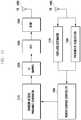
- FIG. 1illustrates a conventional cellular mobile communication system including three cells, each centered around a transmit/receive antennai.e., the transmit/receive antenna is located at the center of each cell.
- the cellsare commonly referred to as a Central Antenna System (CAS).
- CASCentral Antenna System
- each of cells 100, 110, and 120is centered around an antenna (or centrally located antennas) 130 assocated with an evolved Node B (eNB).
- the eNBserves first and second User Equipment (UEs) 130 and 140 within cells 100, 110, and 120 to provide mobile communication service.
- UEsUser Equipment
- the first UE 140is served at comparatively lower data rate than the second UE 150, because the first UE 140 is farther from the antenna 130 than the second UE 150.
- each eNBtransmits reference signals for a UE to measure a downlink channel state and modulate downlink signals.
- 3GPP3 rd Generation Partnership Project
- LTE-ALong Term Evolution-Advanced
- the UEestimates channel with DeModulation Reference Signal (DM-RS) and measures a channel state between the eNB and the UE based on Channel Status Information Reference Signal (CSI-RS), the DM-RS and CSI-RS being transmitted by eNB.
- DM-RSDeModulation Reference Signal
- CSI-RSChannel Status Information Reference Signal
- FIG. 2illustrates a conventional resource block including CSI-RSs transmitted by an eNB. Specifically, FIG. 2 illustrates a downlink reference signal structure with a DM-RS and a CSI-RS transmitted from an eNB to a UE in an LTE-A system.
- the x axisis the time axis
- the y axisis the frequency axis.
- a minimum transmission unit in the time domainis an Orthogonal Frequency Division Multiplxing (OFDM) symbol
- a subframe 224includes two slots 222 and 223, each including N symbol DL symbols.
- a minimum transmission unit in the frequency domainis a subcarrier, and the system frequency band is divided into a total of N BW subcarriers.
- a basic unit of a time-frequency resourceis a Resource Element (RE), which is defined by an OFDM index symbol index and a subcarrier index.
- REResource Element
- a Resource Block (RB) 220 or 221is defined with N symbol DL contiguous OFDM symbols in the time domain and N SC RB contiguous subcarriers in the frequency domain. That is, one RB includes N symbol DL x N SC RB REs.
- a minimum transmission unit of normal data or control informationis a RB.
- the downlink control channelis transmitted in the first three OFDM symbols at the beginning of the subframe 224.
- a Physical Downlink Share Channel (PDSCH)is transmitted on the remaining resources, after those allocated for the downlink control channel in the subframe.
- the DM-RSis the reference signal that is referenced by a UE to demodulate the PDSCH.
- the RB of FIG. 2is designed to transmit strings for two CSI-RS antenna powers at the positions denoted by reference numbers 200 to 219. Specifically, reference numbers 200 to 219 denote the positions paired for the signals of two CSI-RS antenna ports. Accordingly, the eNB transmits the downlink estimation signals for the two CSI-RS antenna ports at the position 200.
- An antenna portis a logical concept, such that CSI-RS is logically defined per CSI-RS antenna port for channel status measurements of a respective CSI-RS antenna port. If the same CSI-RS is transmitted through multiple physical antennas, the UE cannot discriminate among the physical antennas but just recognizes a single antenna port.
- a CSI-RSat cell-specific location, as illustrated in FIG. 2 .
- the CSI-RScan be transmitted at position 200 in cell 100, the CSI-RS is transmitted at position 205 in cell 110, and the CSI-RS can be transmitted at position 210 in cell 120.
- the cellsare assigned different time-frequency resources for the CSI-RS in order to avoid interference between the CSI-RSs of different cells.
- each eNBIn a CAS as illustrated in FIG. 1 , however, the antennas of each eNB are concentrated at the center of cells limiting the ENBs abilities to provide a high data rate service to a UE located far from the center of the cell.
- FIG. 3illustrates a conventional mobile communication system configured with both a CAS and a Distributed Antenna System (DAS).
- DASDistributed Antenna System
- the mobile communication systemincludes cells 300, 310, and 320.
- the first cell 300includes a central antenna 330 and four distributed antennas 360, 370, 380, and 390.
- the central antenna 330 and the distributed antennas 360, 370, 380, and 390are connected each other and controlled by a central controller of an eNB.
- the central antenna 330provides mobile communication service to first and second UEs 340 and 350 located in the first cell 300. However, because the first UE 340 is located farther from the central antenna 330 than the second UE 350, the first UE 340 is served by the eNB at a comparatively lower data rate than the second UE 350.
- the propagation path of the signalelongates, received signal quality degrades.
- a plurality of distributed antennas 360, 370, 380, and 390within the cell 300 and providing the first and second UEs 340 and 350 with the mobile communication service through the distributed antennas 360, 370, 380, and 390, selected according to the locations of the first and second UEs 340 and 350, it is possible to improve the data rate.
- the first UE 340communicates through distributed antenna 390, which provides the best channel environment for the first UE 340
- the second UE 350communicates through distributed antenna 360, which provides the best channel environment for the second UE 350.
- each of the first and second UEs 340 and 350may be served by the eNB at a high data rate.
- the central antenna 330supports normal mobile communication services, service not characterized as high speed data services, and the mobility of the first and second UEs 340 and 350 crossing the boundaries of the cells 300, 310, and 320.
- Each of the central and distributed antennasmay include a plurality of antenna ports.
- FIG. 4illustrates a conventional mobile communication system configured with central antennas distributed throughout a cell.
- the mobile communication systemincludes a plurality of cells 400, 410, and 420, each cell including a plurality of central antennas 430, 431, 432, 433, and 434 distributed throughout the cell and a plurality of distributed antennas 460, 470, 480, and 490 distributed in the cell.
- the central antennas 430, 431, 432, 433, and 434are provide first and second UEs 440 and 450 with normal mobile communication services, i.e., those not characterized as high speed data services, and support mobility of the first and second UEs 440 and 450 roaming across the cells 400, 410, and 420.
- the distributed antennas 460, 470, 480, and 490provide high speed mobile communication services.
- C-portCentral antenna port
- D-portDistributed antenna port
- the C-portdefines a CSI-RS to support CAS for each antenna port, such that a UE can measure a channel status for each antenna port of the C-port.
- the CSI-RS transmitted through the C-portcovers an entire area of a cell.
- the D-portdefines a CSI-RS to support a DAS for each antenna port, such that a UE can measure a channel status for each antenna port of the D-port.
- the CSI-RS transmitted through the D-portcovers a local area within the cell. However, if the same CSI-RS is transmitted through multiple antennas, the UE cannot discriminate between the antennas located at different positions , but instead identifies the same antenna port.
- the first UE 340can measure the channel state between the third distributed antenna 380 and the first UE 340 based on the CSI-RS #1 and the channel state between the fourth distributed antenna 390 and the first UE 340 based on the CSI-RS #2.
- the third distributed antenna 380is referred to as D-port #1
- the fourth distributed antenna 390is referred to as D-port #2.
- the first UE 340cannot discriminate between the third and fourth distributed antennas 380 and 390 using the CSI-RS #3.
- the first UE 340measures the channel states between the first UE 340 and the distributed antennas 380 and 390 using CSI-RS #3.
- the combination of the third and fourth antennas 380 and 390is referred to as a D-port #3.
- the time-frequency resources for transmitting C-port CSI-RS and D-port CSI-RSare allocated so as not to overlap with each other, thereby avoiding interference.
- a UEIn attempting an initial connection to the LTE-A system, a UE performs a cell search to acquire downlink timing and frequency synchronization and a cell IDentifier (ID). Thereafter, the UE acquires basic parameters related to communication, e.g., a system bandwidth in the system information transmitted by the eNB. The UE then performs a random access process to transition to a connected state on a link to an eNB.
- IDcell IDentifier
- FIG. 5is a signal flow diagram illustrating a random access process in a conventional mobile communication system.
- a UEtransmits a random access preamble to an eNB in step 501.
- the eNBmeasures the propagation delay between the UE and eNB and acquires uplink synchronization.
- the UEselects a random access preamble randomly in a given random access preamble set.
- the initial transmit power of the random access preambleis determined using a pathloss between the eNB and the UE, as measured by the UE.
- the eNBtransmits a time alignment command to the UE based on the propagation delay measured in step 501.
- the eNBalso transmits scheduling information including uplink resource information and a power control command. If no scheduling information (a random access response) is received from the eNB, the UE repeats step 501.
- the UEreceives uplink data (message 3) including a UE ID to the eNB using the uplink resource allocated in step 502.
- the transmit timing and transmit power of the UEis determined according to the command received from the eNB in step 502.
- step 504if is the eNB determines that the UE has performed the random access process without collision with other UEs, the eNB transmits, to the UE, the data (message 4) including the ID of the UE.
- the UEdetermines that the random access has completed successfully.
- the UEconfigures an initial transmit power of an uplink data channel and/or control channel based on the UE transmit power controlled through the random access.
- step 501if message 3 transmitted by the UE, e.g., collides with data transmitted by another UE, such that the eNB fails receiving the message 3, the eNB stops transmitting data. Further, if message 4 is not received within a predetermined time, the UE determines that the random access has failed, and then repeats step 501.
- US2012/076042discloses a method in which user equipment carries out a process for random access to a base station in a multi-carrier wireless communication system.
- the methodcomprises a step of measuring the channel qualities of one or more uplink component carriers, and determining the uplink component carrier having the highest channel quality; a step of selecting a physical random access channel (PRACH) resource on the uplink component carrier having the highest channel quality; and a step of transmitting a random access preamble to the base station using the selected PRACH resource.
- PRACHphysical random access channel
- the documentfurther discloses to select a UL CC having a highest x as a UL CC for the preamble retransmission.
- the present inventionhas been made in an effort to solve at least the above-described problems occurring in the related art, and to provide at least the following advantages.
- a random access method of a UEis provided through a link having a best channel quality among multiple links between the UE and individual antenna ports in a DAS or combination DAS/CAS.
- the UEcalculates a transmit power for transmitting a random access preamble using a reference antenna transmit power information received from an eNB.
- the reference antenna transmit power informationincludes channel state reference signals for calculating a pathloss between the UE and individual antennas, and a power adjustment parameter of a nearest antenna.
- a methodfor efficiently minimizing UE random access preamble transmit power, thereby reducing UE power consumption and interference.
- FIG. 6illustrates a power control method according to an embodiment of the present invention.
- the first and second antennas 610 and 620are distributed within a cell, a pathloss between the UE 630 and the first antenna 610 is PL1 and a pathloss between the UE 630 and the second antenna 620 is PL2. If the PL1 is less than the PL2 (PL1 ⁇ PL2), the channel state between the UE 630 and the first antenna 610 is better than the channel state between the UE 630 and the second antenna 620.
- the first and second antennas 610 and 620operate with CSI-RSs defined respectively such that the UE 630 can measure a channel state per antenna.
- the first and second antennas 610 and 620can be referred to as antenna ports 1 and 2, respectively, in logical concept. Accordingly, if the same CSI-RS is transmitted through multiple physical antennas, the UE 630 cannot discriminate among the antennas but recognizes the physical antennas as one antenna port.
- the pathlossis a criterion indicating whether the channel state is good or bad; the greater the pathloss, the worse the channel state.
- the pathlosshas a small time-varying characteristic.
- the UEcalculates pathloss using an RS transmitted by the eNB, as shown in Equation (1).
- PLreferenceSignalPower ⁇ RSRP
- Equation (1)PL represents pathloss
- referenceSignalPowerdenotes an RS transmit power signaled by the eNB
- Reference Signal Received Powerdenotes a received signal strength of the RS, as measured by the UE.
- the UEincreases the transmit power to overcome the worsening channel condition.
- a high UE transmit powerincreases power consumption and increases interference, negatively affecting system performance.
- UE power consumption and interferencecan be reduced, if the UE transmit power can be controlled by selecting a link having a best channel condition among multiple links established between the UE and multiple antennas.
- FIG. 7illustrates a transmit power control method in a mobile communication system according to an embodiment of the present invention. Specifically, FIG. 7 illustrates a pathloss-adaptive random access preamble transmit power configuration method.
- a cellincludes a central antenna 710 and first and second distributed antennas 720 and 730 for communication with a UE 740.
- the central antennal 710 and the first and second antennas 720 and 730transmit a CSI-RS in different patterns, respectively. Because the CSI-RS is transmitted in different patterns, the UE 740 can measure the channel state for each antenna.
- FIG. 7it is assumed that the central antenna 710 and the first and second distributed antennas 720 and 730 are mapped to C-port, D-port #1, and D-port #2, respectively. Also, it is assumed that the central antenna 710 and the first and second distributed antennas 720 and 730 are connected to the central controller of the eNB.
- the UE 740is nearest to the first distributed antenna 720 and farthest from the second distributed antenna 730. Therefore, assuming that there are no obstacles between the UE 740 and the antennas 710, 720, and 730, the antennas have a pathloss relationship of PL2 ⁇ PL1 ⁇ PL3, where PL1 is the pathloss between the UE 740 and the central antenna 710, PL2 is the pathloss between the UE 740 and the first distributed antenna 720, and PL3 is the pathloss between the UE 740 and the second distributed antenna 730.
- the UEcan measures the pathloss per antenna using the antenna-specific CSI-RS.
- P PRACHthe UE's random access preamble transmit power
- PCMAXrepresents a maximum UE output power based on a UE class and higher layer signaling configuration
- PREAMBLE_RECEIVED_TARGET_POWERrepresents a random access preamble reception power required for the eNB to receive the random access preamble, determined based on the higher layer signal parameters
- PLrepresents the pathloss between eNB and UE.
- the transmit/receive antennas of the eNBare distributed such that the PLs between the UE 740 and the respective antennas 710, 720, and 730 are different from each other.
- reference numbers 750, 760, and 770denote PREAMBLE_RECEIVED_TARGET_POWER values obtained by applying the PLs between the UE 740 and the respective antennas 710, 720, and 730 to Equation (2) for a CAS mode transmit power calculation.
- the calculated random access preamble transmission powers of the UE 740can be expressed as denoted by reference numbers 791, 792, and 793, where reference number 792 denotes the transmit power between the UE 740 and the central antenna 710, reference number 791 denotes the transmit power between the UE 740 and the first distributed antenna 720, and reference number 793 denotes the transmit power between the UE 740 and the second distributed antenna 730.
- the random access preambleWhen the random access preamble is transmitted at a transmit power as denoted by reference number 791, it is assumed that at least the first distributed antenna 720 will receive the random access preamble.
- the random access preambleis transmitted at a transmit power as denoted by reference number 792, it is assumed that at least the first distributed antenna 720 and the central antenna 710 will receive the random access preamble.
- each of the first distributed antenna 720, the central antenna 710, and the second distributed antenna 730will receive the random access preamble.
- the central and first and second distributed antennas 710, 720, and 730are connected to a central controller. Accordingly, when the random access preamble is received through at least one of the antennas, the eNB will receive the random access preamble successfully.
- P PRACHmin P CMAX , PREAMBLE_RECEIVED_TARGET_POWER + min PL k dBm
- Equation (3)PL(k) represents the pathloss between the UE and a k th antenna port.
- reference number 780denotes a UE random access preamble transmit power obtained using Equation (3)
- reference number 790denotes the pathloss used for determining the random access preamble transmit power.
- FIG. 8is a flowchart illustrating a random access preamble transmit power control method of a UE according to an embodiment of the present invention.
- the UEperforms a cell search to acquire downlink timing, frequency synchronization, and a cell ID.
- the UEreceives control information(specially, system information) from an eNB.
- the system informationincludes reference antenna transmit power information for transmitting a random access preamble.
- the UEacquires basic parameters for communication such as system bandwidth, random access-related parameters, and reference antenna transmit power information including CSI-RS pattern information for measuring pathloss (PL) for each antenna port, in the system information.
- step 803the UE measures PLs between the UE and the respective antennas by referencing the CSI-RS patterns, and then compares the PLs.
- step 804the UE determines the transmit power required for random access preamble transmission using Equation (3). That is, the UE measures the PLs for each antenna and selects the smallest PL. The UE then determines the transmit power by applying the selected PL value to Equation 3.
- step 805the UE transmits a random access preamble at the determined transmit power.
- step 806the UE determines whether a random access response is received from the eNB. If no random access response is received within a predetermined time, the procedure returns to step 805 and the UE retransmits the random access preamble. If the random access response is received in step 806, in step 807, the UE transmits a message 3 to the eNB by referencing scheduling information included in the random access response.
- step 808the UE determines whether a message 4 is received from the eNB. If the message 4 is not received within a predetermined time, the procedure returns to step 805 and the UE retransmits the random access preamble. If, however, the message 4 is received in step 808, the UE completes the random access procedure successfully.
- FIG. 9is a flowchart illustrating a random access preamble transmit power control method of an eNB according to an embodiment of the present invention.
- step 901the eNB transmits, to a UE, communication-related basic parameters such as system information, random access-related parameters, and per-antenna power CSI-RS pattern information.
- step 902the eNB determines whether a random access preamble is received form the UE. If the random access preamble is not received within a predetermined time, the procedure returns to step 902 and the eNB waits to receive a random access preamble.
- the eNBtransmits, to the UE, a random access response including a time alignment command and scheduling information determined based on the information included in the random access preamble.
- the eNBdetermines whether a message 3 is received from the UE. If the message 3 is received successfully, the eNB transmits a message 4 to the UE. However, if the message 3 is not received, the procedure returns to step 902 and the eNB waits to receive another random access preamble.
- the eNBcan notify the UE of a random access preamble to be used.
- the random access preamble designated by the eNBis referred to as dedicated random access preamble.
- steps 807 and 808 in FIG. 8 and steps 904 and 905 in FIG. 9can be omitted.
- the random access procedurealso can be triggered in a handover as a cell switching process of the UE. More specifically, if the eNB commands the UE to perform a handover from cell A to Cell B, the UE performs random access to the cell B and then performs the operations for communication in the cell B. In this case, the eNB provides the UE with information about cell A and cell B and CSI-RS pattern information set for PL measurement for each antenna in cell A and cell B.
- the eNBalso notifies the UE of the CSI-RS pattern to be used for PL measurement through separate signaling.
- the eNBIf the UE is located within cell A, the eNB notifies the UE of the CSI-RS pattern information #1, CSI-RS pattern information #2, and CSI-RS pattern information #3 for the UE's PL measurement in the CSI-RS pattern information set.
- the eNBcan notify the UE of CSI-RS pattern information #4, CSI-RS pattern information #5, and CSI-RS pattern information #6 for PL measurement in the CSI-RS pattern information set. Accordingly, the eNB can notify the UE of the CSI-RS pattern information for use in PL measurement for each antenna in the entire system without discrimination among cells.
- the eNBcan also notify the UE of partial CSI-RS pattern information for PL measurement according to a specific situation.
- the UEperforms PL measurement using the CSI-RS pattern information from the eNB and determines transmit power based on the measurement result.
- the UEcan determine the transmit power using the minimum PL value among PLs of individual antennas corresponding to the UE and the notified CSI-RS patterns as shown above in Equation (3). Also, the transmit power can be determined as an average value of the PLs of respective antennas corresponding to the UE and the CSI-RS patterns.
- FIG. 10illustrates a transmit power control method of a UE in a mobile communication system according to an example. Specifically, FIG. 10 illustrates a method for determining a random access preamble transmit power using parameters for compensating for a channel condition between a UE and a predetermined antenna signaled by an eNB.
- a cellincludes a central antenna 1010 and first and second distributed antennas 1020 and 1030 for communication with a UE 1040.
- the central antennal 1010 and the first and second antennas 1020 and 1030transmit CSI-RS in different patterns. That is, the central antenna 1010 is mapped to C-port, the first distributed antenna 1020 to D-port #1, and the second distributed antenna 1030 to D-port #2.
- the central and first and second distributed antennas 1010, 2030, and 2030are connected to a central controller of the eNB.
- the UEmeasures pathloss between the UE and the C-port covering the entire cell area under the assumption that the UE performs pathloss measurement on a single antenna.
- the eNBsignals an additional power control parameter ⁇ for adjusting a random access preamble transmit power of the UE based on a location of the UE.
- the UEdetermines the random access preamble transmit power according to Equation (4).
- P RACHmin P CMAX , PREAMBLE_RECEIVED_TARGET_POWER + PL + ⁇ dBm
- PCMAXrepresents a maximum UE output power determined based on a UE class and higher layer signaling configuration
- PREAMBLE_RECEIVED_TARGET_POWERrepresents a random access preamble reception power required for the eNB to receive the random access preamble, which is determined based on the higher layer signal parameters
- PLrepresents pathloss between the eNB and the UE
- ⁇represents an additional power control parameter for adjusting the random access preamble transmit power of the UE.
- reference number 1050denotes an example of determining the transmit power 1080 by adjusting a UE random access preamble transmit power calculated using Equation (4) with the additional power control parameter ⁇ 1060.
- ⁇ 1060is the power control parameter generated in associated with an antenna communicating with the UE(for example, association with a nearest antenna to the UE), based on the UE location.
- ⁇ 1060can be set to 0 or a negative value.
- Equation (2)the random access preamble transmit power is calculated as denoted by reference number 1070. Accordingly, the random access preamble transmit power calculated by Equation (4), i.e., by reflecting ⁇ 1060, is less than the value calculated by Equation (2), thereby reducing power consumption.
- FIG. 11is a flowchart illustrating a random access preamble transmit power control method of a UE according to an example.
- the UEperforms a cell search to acquire downlink timing, frequency synchronization, and a cell ID.
- the UEreceives system information including reference antenna transmit power information for random access preamble transmission from an eNB.
- the UEacquires basic parameters for communication such as system bandwidth, random access-related parameters, and ⁇ for adjusting random access preamble transmit power as reference antenna transmission power information.
- ⁇is a parameter for controlling the transmit power in association with the antenna nearest to the UE location which is checked by the eNB.
- step 1103the UE determines the transmit power required for random access preamble transmission using Equation (4) with the random access-related parameters, the power control parameter ⁇ for adjusting the random access preamble transmit power, and the pathloss measured for C-port.
- step 1104the UE transmits the random access preamble at the transmit power level.
- step 1105the UE determines whether a random access response is received form the eNB. If the random access response is not received within a predetermined time, the procedure returns to step 1104 and the UE retransmits the random access preamble. If the random access response is received in step 1105, in step 1106, the UE transmits a message 3, according to the scheduling information included in the random access response.
- step 1107the UE determines whether a message 4 is received. If the message 4 is not received within a predetermined time, the procedure returns to step 1104 and the UE retransmits the random access preamble. However, if the message 4 is received in step 1107, the UE completes the random access procedure successfully.
- FIG. 12is a flowchart illustrating a random access preamble transmit power control method of an eNB according to an example.
- step 1201the eNB transmits, to a UE, communication-related basic parameters such as the system information, random access-related parameters, and random access preamble transmit power control parameter ⁇ .
- step 1202the eNB determines whether a random access preamble is received. Basically, the eNB waits until the random access preamble is received at step 1202.
- step 1203the eNB transmits, to the UE, a random access response including a time alignment command and scheduling information determined based on the information included in the random access preamble.
- step 1204the eNB determines whether a message 3 is received. If the message 3 is not received, the procedure to step 1202 and the eNB waits to receives another random access preamble. However, if the message 3 is received in step 1204, the eNB transmits a message 4 to the UE in step 1205. If the UE receives the message 4 successfully, the random access procedure is terminated.
- the eNBcan notify the UE of the random access preamble to be used, i.e., a dedicated random access preamble can be used.
- a dedicated random access preamblecan be used.
- ⁇is not signaled explicitly but notified implicitly with the transmission of the dedicated random access preamble.
- the relationship between the dedicated random access preamble and ⁇can be defined as follows and shared by the eNB and UE.
- steps 1106 and 1107 in FIG. 11 and steps 1204 and 1205 in FIG. 12can be omitted.
- FIG. 13illustrates a UE according to an embodiment of the present invention.
- the UEincludes a random access preamble generator 1310 for generating the random access preamble, a Resource Element (RE) mapper 1320 for mapping a signal to be transmitted to REs, an Inverse Fast Fourier Transform (IFFT) processor 1330 for performing IFFT on the signal output from the RE mapper 1320, an Intermediate Frequency/Radio Frequency (IF/RF) processor 1340 for performing IF/RF conversion on the signal output from the IFFT processor 1330, and a transmitter 1350 for transmitting the radio signal output by the IF/RF processor 1340.
- REResource Element
- IFFTInverse Fast Fourier Transform
- IF/RFIntermediate Frequency/Radio Frequency
- the UEreceives the system information from the eNB through the receiver 1360.
- the system informationincludes the basic communication parameters such as the system bandwidth, per-antenna CSI-RS pattern information on the random access-related parameters and reference antenna transmit power, and random access preamble transmit power control information ⁇ .
- the UEchecks the pathloss between the eNB and the UE and the pathloss between each antenna and the UE using a pathloss estimator 1370.
- the UEalso acquires the random access-related parameter from the eNB using a parameter acquisition unit 1380.
- the UEadjusts the random access preamble transmit power of the UE using the checked pathloss and random access-related parameters using a power control controller 1390.
- the UEdetermines the random access preamble transmit power as described above, and the power control controller 1390 controls the random access preamble generator 1310 and/or the IF/RF processor 1340 to adjust the random access preamble transmit power.
- FIG. 14illustrates an eNB according to an example.
- the eNBincludes a receiver 1401, an RF/IF processor 1402 for performing RF/IF conversion on a signal received by the receiver 1401, a Fast Fourier Transform (FFT) processor 1403 for performing FFT on the output of the RF/IF processor 1402, an RE demapper 1404, a random access preamble detector 1405, and a power control controller 1406.
- FFTFast Fourier Transform
- the power control controller 1406generates a power control parameter for random access preamble transmission according to the location of the UE to a control information generator 1407.
- the control information generator 1407generates control information based on the power control parameter input by the power control controller 1406 and the information provided by the random access preamble detector 1405 on whether the random access preamble is received successfully.
- the control informationis coded with an error correction code by an encoder 1408, is modulated to a modulation symbol by a modulator 1409. and is then mapped to the time-frequency resource by an RE mapper 1410.
- the signalis further processed by an IF/RF processor 1412 and then transmitted to the UE by a transmitter 1413.
- Random access preamble transmit power control methods and apparatusesare capable of efficiently controlling the random access preamble transmit power in a DAS-based mobile communication system, thereby reducing power consumption and interference.
Landscapes
- Engineering & Computer Science (AREA)
- Computer Networks & Wireless Communication (AREA)
- Signal Processing (AREA)
- Mobile Radio Communication Systems (AREA)
Description
- The present invention relates generally to a mobile terminal and power control method for random access of the mobile terminal, and in particular, to a power control method and apparatus of a mobile terminal that facilitates a random access procedure in a distributed antenna mobile communication system.
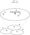
FIG. 1 illustrates a conventional cellular mobile communication system including three cells, each centered around a transmit/receive antennai.e., the transmit/receive antenna is located at the center of each cell. The cells are commonly referred to as a Central Antenna System (CAS). Even when multiple antennas are provided, all of these antennas are arranged at the center of the cell to define the service area.- Referring to
FIG. 1 , each ofcells cells cell 100, i.e., the service area of the eNB using theantenna 130, the first UE 140 is served at comparatively lower data rate than the second UE 150, because the first UE 140 is farther from theantenna 130 than the second UE 150. - In a mobile communication system implemented with the CAS-based antenna formation as illustrtaed in
FIG. 1 , each eNB transmits reference signals for a UE to measure a downlink channel state and modulate downlink signals. For 3rd Generation Partnership Project (3GPP) Long Term Evolution-Advanced (LTE-A), the UE estimates channel with DeModulation Reference Signal (DM-RS) and measures a channel state between the eNB and the UE based on Channel Status Information Reference Signal (CSI-RS), the DM-RS and CSI-RS being transmitted by eNB. FIG. 2 illustrates a conventional resource block including CSI-RSs transmitted by an eNB. Specifically,FIG. 2 illustrates a downlink reference signal structure with a DM-RS and a CSI-RS transmitted from an eNB to a UE in an LTE-A system.- Referring to
FIG. 2 , the x axis is the time axis, and the y axis is the frequency axis. A minimum transmission unit in the time domain is an Orthogonal Frequency Division Multiplxing (OFDM) symbol, and asubframe 224 includes twoslots - In
FIG. 2 , the downlink control channel is transmitted in the first three OFDM symbols at the beginning of thesubframe 224. A Physical Downlink Share Channel (PDSCH) is transmitted on the remaining resources, after those allocated for the downlink control channel in the subframe. The DM-RS is the reference signal that is referenced by a UE to demodulate the PDSCH. - The RB of
FIG. 2 is designed to transmit strings for two CSI-RS antenna powers at the positions denoted byreference numbers 200 to 219. Specifically, ,reference numbers 200 to 219 denote the positions paired for the signals of two CSI-RS antenna ports. Accordingly, the eNB transmits the downlink estimation signals for the two CSI-RS antenna ports at theposition 200. - An antenna port is a logical concept, such that CSI-RS is logically defined per CSI-RS antenna port for channel status measurements of a respective CSI-RS antenna port. If the same CSI-RS is transmitted through multiple physical antennas, the UE cannot discriminate among the physical antennas but just recognizes a single antenna port.
- In a mobile communication systems including a plurality of cells, as illustrates in
FIG. 1 , it is possible to transmit a CSI-RS at cell-specific location, as illustrated inFIG. 2 . - For example, the CSI-RS can be transmitted at
position 200 incell 100, the CSI-RS is transmitted atposition 205 incell 110, and the CSI-RS can be transmitted atposition 210 incell 120. Basically, the cells are assigned different time-frequency resources for the CSI-RS in order to avoid interference between the CSI-RSs of different cells. - In a CAS as illustrated in
FIG. 1 , however, the antennas of each eNB are concentrated at the center of cells limiting the ENBs abilities to provide a high data rate service to a UE located far from the center of the cell. FIG. 3 illustrates a conventional mobile communication system configured with both a CAS and a Distributed Antenna System (DAS).- Referring to
FIG. 3 , the mobile communication system includescells first cell 300 includes acentral antenna 330 and fourdistributed antennas central antenna 330 and thedistributed antennas - The
central antenna 330 provides mobile communication service to first and second UEs 340 and 350 located in thefirst cell 300. However, because the first UE 340 is located farther from thecentral antenna 330 than the second UE 350, the first UE 340 is served by the eNB at a comparatively lower data rate than the second UE 350. - Typically, as the propagation path of the signal elongates, received signal quality degrades. By deploying a plurality of
distributed antennas cell 300 and providing the first andsecond UEs distributed antennas second UEs distributed antenna 390, which provides the best channel environment for the first UE 340, and the second UE 350 communicates throughdistributed antenna 360, which provides the best channel environment for the second UE 350. Accordingly, each of the first andsecond UEs - Normally, the
central antenna 330 supports normal mobile communication services, service not characterized as high speed data services, and the mobility of the first andsecond UEs cells FIG. 4 illustrates a conventional mobile communication system configured with central antennas distributed throughout a cell.- Referring to
FIG. 4 , the mobile communication system includes a plurality ofcells central antennas distributed antennas central antennas second UEs second UEs cells distributed antennas - In the following description, the logical concepts of a Central antenna port (C-port) and a Distributed antenna port (D-port) are defined such that the central and distributed antennas can be discriminated logically from each other regardless of their physical configurations.
- The C-port defines a CSI-RS to support CAS for each antenna port, such that a UE can measure a channel status for each antenna port of the C-port. The CSI-RS transmitted through the C-port covers an entire area of a cell.
- The D-port defines a CSI-RS to support a DAS for each antenna port, such that a UE can measure a channel status for each antenna port of the D-port. The CSI-RS transmitted through the D-port covers a local area within the cell. However, if the same CSI-RS is transmitted through multiple antennas, the UE cannot discriminate between the antennas located at different positions , but instead identifies the same antenna port.
- For example, in
FIG. 3 , if the third andfourth antennas distributed antenna 380 and the first UE 340 based on the CSI-RS #1 and the channel state between the fourthdistributed antenna 390 and the first UE 340 based on the CSI-RS #2. In this case, the thirddistributed antenna 380 is referred to as D-port # 1, and the fourthdistributed antenna 390 is referred to as D-port # 2. - If the third and fourth
distributed antennas distributed antennas distributed antennas fourth antennas port # 3. - The time-frequency resources for transmitting C-port CSI-RS and D-port CSI-RS are allocated so as not to overlap with each other, thereby avoiding interference.
- In attempting an initial connection to the LTE-A system, a UE performs a cell search to acquire downlink timing and frequency synchronization and a cell IDentifier (ID). Thereafter, the UE acquires basic parameters related to communication, e.g., a system bandwidth in the system information transmitted by the eNB. The UE then performs a random access process to transition to a connected state on a link to an eNB.
FIG. 5 is a signal flow diagram illustrating a random access process in a conventional mobile communication system.- Referring to
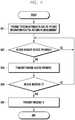
FIG. 5 , a UE transmits a random access preamble to an eNB instep 501. The eNB measures the propagation delay between the UE and eNB and acquires uplink synchronization. The UE selects a random access preamble randomly in a given random access preamble set. The initial transmit power of the random access preamble is determined using a pathloss between the eNB and the UE, as measured by the UE. - In
step 502, the eNB transmits a time alignment command to the UE based on the propagation delay measured instep 501. The eNB also transmits scheduling information including uplink resource information and a power control command. If no scheduling information (a random access response) is received from the eNB, the UE repeatsstep 501. - In step 5030, the UE receives uplink data (message 3) including a UE ID to the eNB using the uplink resource allocated in
step 502. The transmit timing and transmit power of the UE is determined according to the command received from the eNB instep 502. - In
step 504, if is the eNB determines that the UE has performed the random access process without collision with other UEs, the eNB transmits, to the UE, the data (message 4) including the ID of the UE. When themessage 4 is received from the eNB, the UE determines that the random access has completed successfully. When the random access has completed successfully, the UE configures an initial transmit power of an uplink data channel and/or control channel based on the UE transmit power controlled through the random access. - However, if
message 3 transmitted by the UE, e.g., collides with data transmitted by another UE, such that the eNB fails receiving themessage 3, the eNB stops transmitting data. Further, ifmessage 4 is not received within a predetermined time, the UE determines that the random access has failed, and then repeatsstep 501. US2012/076042 discloses a method in which user equipment carries out a process for random access to a base station in a multi-carrier wireless communication system. The method comprises a step of measuring the channel qualities of one or more uplink component carriers, and determining the uplink component carrier having the highest channel quality; a step of selecting a physical random access channel (PRACH) resource on the uplink component carrier having the highest channel quality; and a step of transmitting a random access preamble to the base station using the selected PRACH resource. The document further discloses to select a UL CC having a highest x as a UL CC for the preamble retransmission.- The present invention has been made in an effort to solve at least the above-described problems occurring in the related art, and to provide at least the following advantages.
- Accordingly, a power control method according to
claim 1 and an apparatus for controlling transmit power according toclaim 6 are provided. Favourable embodiments are defined in the dependent claims. - The above and other aspects, features, and advantages of certain embodiments of the present invention will be more apparent from the following description taken in conjunction with the accompanying drawings, in which:
FIG. 1 illustrates a conventional cellular mobile communication system including three cells, each centered around a transmit/receive antenna;FIG. 2 illustrates a conventional resource block including CSI-RSs transmitted by an eNB;FIG. 3 illustrates a conventional mobile communication system configured with both CAS and DAS;FIG. 4 illustrates a conventional mobile communication system configured with central antennas distributed throughout a cellFIG. 5 is a signal flow diagram illustrating a random access process in a conventional mobile communication system;FIG. 6 illustrates a power control method according to an embodiment of the present invention;FIG. 7 illustrates a transmit power control method in a mobile communication system according to an embodiment of the present invention;FIG. 8 is a flowchart illustrating a random access preamble transmit power control method of a UE according to an embodiment of the present invention;FIG. 9 is a flowchart illustrating a random access preamble transmit power control method of an eNB according to an embodiment of the present invention;FIG. 10 illustrates transmit power control method in a mobile communication system according to an example;FIG. 11 is a flowchart illustrating a random access preamble transmit power control method of a UE according to an example;FIG. 12 is a flowchart illustrating a random access preamble transmit power control method of an eNB according to an example;FIG. 13 illustrates a UE according to an embodiment of the present invention; andFIG. 14 illustrates an eNB according to an example.- Various embodiments of the present invention are described in detail below with reference to the accompanying drawings. Detailed descriptions of well-known functions and structures incorporated herein may be omitted to avoid obscuring the subject matter of the present invention. Further, the following terms are defined in consideration of the functionality in the present invention, and may vary according to the intention of a user or an operator, usage, etc. Therefore, the definition should be made on the basis of the overall content of the present specification.
- Although embodiments of the present invention will be described herein with reference to LTE-A (or Advanced Evolved Universal Terrestrial Radio Access (EUTRA)) by way of example, it will be understood by those skilled in the art that the embodiments of the present invention can be applied to other communication systems having similar technical backgrounds and channel formats, with slight modifications, without departing from the scope of the present invention as defined by the appended claims.
- In accordance with an embodiment of the present invention, a random access method of a UE is provided through a link having a best channel quality among multiple links between the UE and individual antenna ports in a DAS or combination DAS/CAS.
- In the random access process, the UE calculates a transmit power for transmitting a random access preamble using a reference antenna transmit power information received from an eNB. The reference antenna transmit power information includes channel state reference signals for calculating a pathloss between the UE and individual antennas, and a power adjustment parameter of a nearest antenna.
- In accordance with an embodiment of the present invention, a method is provided for efficiently minimizing UE random access preamble transmit power, thereby reducing UE power consumption and interference.
FIG. 6 illustrates a power control method according to an embodiment of the present invention.- Referring to
FIG. 6 , the first andsecond antennas UE 630 and thefirst antenna 610 is PL1 and a pathloss between theUE 630 and thesecond antenna 620 is PL2. If the PL1 is less than the PL2 (PL1<PL2), the channel state between theUE 630 and thefirst antenna 610 is better than the channel state between theUE 630 and thesecond antenna 620. - The first and
second antennas UE 630 can measure a channel state per antenna. The first andsecond antennas antenna ports UE 630 cannot discriminate among the antennas but recognizes the physical antennas as one antenna port. - The pathloss is a criterion indicating whether the channel state is good or bad; the greater the pathloss, the worse the channel state. The pathloss has a small time-varying characteristic. Typically, the UE calculates pathloss using an RS transmitted by the eNB, as shown in Equation (1).

- In Equation (1), PL represents pathloss, referenceSignalPower denotes an RS transmit power signaled by the eNB, and Reference Signal Received Power (RSRP) denotes a received signal strength of the RS, as measured by the UE.
- As the pathloss increases, the UE increases the transmit power to overcome the worsening channel condition. However, a high UE transmit power increases power consumption and increases interference, negatively affecting system performance. In a DAS-based mobile communication system, UE power consumption and interference can be reduced, if the UE transmit power can be controlled by selecting a link having a best channel condition among multiple links established between the UE and multiple antennas.
FIG. 7 illustrates a transmit power control method in a mobile communication system according to an embodiment of the present invention. Specifically,FIG. 7 illustrates a pathloss-adaptive random access preamble transmit power configuration method.- Referring to
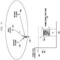
FIG. 7 , a cell includes acentral antenna 710 and first and second distributedantennas UE 740. Here, it is assumed that thecentral antennal 710 and the first andsecond antennas UE 740 can measure the channel state for each antenna. - In
FIG. 7 , it is assumed that thecentral antenna 710 and the first and second distributedantennas port # 1, and D-port # 2, respectively. Also, it is assumed that thecentral antenna 710 and the first and second distributedantennas - The
UE 740 is nearest to the first distributedantenna 720 and farthest from the second distributedantenna 730. Therefore, assuming that there are no obstacles between theUE 740 and theantennas UE 740 and thecentral antenna 710, PL2 is the pathloss between theUE 740 and the first distributedantenna 720, and PL3 is the pathloss between theUE 740 and the second distributedantenna 730. The UE can measures the pathloss per antenna using the antenna-specific CSI-RS. - In an LTE-A system operating in a CAS mode, the UE's random access preamble transmit power (PPRACH) is expressed in units of dBm, as shown in Equation (2).

- In Equation (2), PCMAX represents a maximum UE output power based on a UE class and higher layer signaling configuration,PREAMBLE_RECEIVED_TARGET_POWER represents a random access preamble reception power required for the eNB to receive the random access preamble, determined based on the higher layer signal parameters, and PL represents the pathloss between eNB and UE.
- In a DAS mode, however, the transmit/receive antennas of the eNB are distributed such that the PLs between the
UE 740 and therespective antennas - In
FIG. 7 ,reference numbers UE 740 and therespective antennas UE 740 can be expressed as denoted byreference numbers reference number 792 denotes the transmit power between theUE 740 and thecentral antenna 710,reference number 791 denotes the transmit power between theUE 740 and the first distributedantenna 720, andreference number 793 denotes the transmit power between theUE 740 and the second distributedantenna 730. - When the random access preamble is transmitted at a transmit power as denoted by
reference number 791, it is assumed that at least the first distributedantenna 720 will receive the random access preamble. When the random access preamble is transmitted at a transmit power as denoted byreference number 792, it is assumed that at least the first distributedantenna 720 and thecentral antenna 710 will receive the random access preamble. Further, when the random access preamble is transmitted at a transmit power as denoted byreference number 793, it is assumed that each of the first distributedantenna 720, thecentral antenna 710, and the second distributedantenna 730 will receive the random access preamble. - The central and first and second distributed
antennas - As described above, UE power consumption can be reduced by minimizing the transmit power of the
UE 740. A UE transmit power reduction is advantageous reducing system interferences. Therefore, in accordance with an embodiment of the present invention, a method is provided for determining a random access preamble transmit power from a power calculated based on a minimum pathloss among pathloss values (PLs) associated with respective antennas operating in a DAS mode. That is, a UE can determine a random access preamble transmit power using Equation (3) instead of Equation (2).
- In Equation (3), PL(k) represents the pathloss between the UE and a kth antenna port.
- In
FIG. 7 ,reference number 780 denotes a UE random access preamble transmit power obtained using Equation (3), andreference number 790 denotes the pathloss used for determining the random access preamble transmit power. FIG. 8 is a flowchart illustrating a random access preamble transmit power control method of a UE according to an embodiment of the present invention.- Referring to
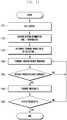
FIG. 8 , instep 801, the UE performs a cell search to acquire downlink timing, frequency synchronization, and a cell ID. Instep 802, the UE receives control information(specially, system information) from an eNB. The system information includes reference antenna transmit power information for transmitting a random access preamble. The UE acquires basic parameters for communication such as system bandwidth, random access-related parameters, and reference antenna transmit power information including CSI-RS pattern information for measuring pathloss (PL) for each antenna port, in the system information. - In
step 803, the UE measures PLs between the UE and the respective antennas by referencing the CSI-RS patterns, and then compares the PLs. Instep 804, the UE determines the transmit power required for random access preamble transmission using Equation (3). That is, the UE measures the PLs for each antenna and selects the smallest PL. The UE then determines the transmit power by applying the selected PL value toEquation 3. - In
step 805, the UE transmits a random access preamble at the determined transmit power. Instep 806, the UE determines whether a random access response is received from the eNB. If no random access response is received within a predetermined time, the procedure returns to step 805 and the UE retransmits the random access preamble. If the random access response is received instep 806, instep 807, the UE transmits amessage 3 to the eNB by referencing scheduling information included in the random access response. - In
step 808, the UE determines whether amessage 4 is received from the eNB. If themessage 4 is not received within a predetermined time, the procedure returns to step 805 and the UE retransmits the random access preamble. If, however, themessage 4 is received instep 808, the UE completes the random access procedure successfully. FIG. 9 is a flowchart illustrating a random access preamble transmit power control method of an eNB according to an embodiment of the present invention.- Referring to
FIG. 9 , instep 901, the eNB transmits, to a UE, communication-related basic parameters such as system information, random access-related parameters, and per-antenna power CSI-RS pattern information. Instep 902, the eNB determines whether a random access preamble is received form the UE. If the random access preamble is not received within a predetermined time, the procedure returns to step 902 and the eNB waits to receive a random access preamble. - If the random access preamble is received, in
step 903, the eNB transmits, to the UE, a random access response including a time alignment command and scheduling information determined based on the information included in the random access preamble. In step 604, the eNB determines whether amessage 3 is received from the UE. If themessage 3 is received successfully, the eNB transmits amessage 4 to the UE. However, if themessage 3 is not received, the procedure returns to step 902 and the eNB waits to receive another random access preamble. - Alternatively, the eNB can notify the UE of a random access preamble to be used. In this case, the random access preamble designated by the eNB is referred to as dedicated random access preamble. In a random access process using a dedicated random access preamble, there is no probability of collision among random access preambles transmitted by different UEs. Accordingly, steps 807 and 808 in
FIG. 8 andsteps FIG. 9 can be omitted. - Additionally, the random access procedure also can be triggered in a handover as a cell switching process of the UE. More specifically, if the eNB commands the UE to perform a handover from cell A to Cell B, the UE performs random access to the cell B and then performs the operations for communication in the cell B. In this case, the eNB provides the UE with information about cell A and cell B and CSI-RS pattern information set for PL measurement for each antenna in cell A and cell B.
- For example, the eNB sends the UE the CSI-RS pattern information set = {CSI-RS
pattern information # 1, CSI-RSpattern information # 2, CSI-RSpattern information # 3, CSI-RSpattern information # 4, CSI-RSpattern information # 5, CSI-RS pattern information #6}. The eNB also notifies the UE of the CSI-RS pattern to be used for PL measurement through separate signaling. - If the UE is located within cell A, the eNB notifies the UE of the CSI-RS
pattern information # 1, CSI-RSpattern information # 2, and CSI-RSpattern information # 3 for the UE's PL measurement in the CSI-RS pattern information set. When the handover from cell A to cell B is commanded, the eNB can notify the UE of CSI-RSpattern information # 4, CSI-RSpattern information # 5, and CSI-RSpattern information # 6 for PL measurement in the CSI-RS pattern information set. Accordingly, the eNB can notify the UE of the CSI-RS pattern information for use in PL measurement for each antenna in the entire system without discrimination among cells. The eNB can also notify the UE of partial CSI-RS pattern information for PL measurement according to a specific situation. - The UE performs PL measurement using the CSI-RS pattern information from the eNB and determines transmit power based on the measurement result. The UE can determine the transmit power using the minimum PL value among PLs of individual antennas corresponding to the UE and the notified CSI-RS patterns as shown above in Equation (3). Also, the transmit power can be determined as an average value of the PLs of respective antennas corresponding to the UE and the CSI-RS patterns.
FIG. 10 illustrates a transmit power control method of a UE in a mobile communication system according to an example. Specifically,FIG. 10 illustrates a method for determining a random access preamble transmit power using parameters for compensating for a channel condition between a UE and a predetermined antenna signaled by an eNB.- Referring to
FIG. 10 , a cell includes acentral antenna 1010 and first and second distributedantennas UE 1040. The central antennal 1010 and the first andsecond antennas central antenna 1010 is mapped to C-port, the first distributedantenna 1020 to D-port # 1, and the second distributedantenna 1030 to D-port # 2. The central and first and second distributedantennas 1010, 2030, and 2030 are connected to a central controller of the eNB. - In
FIG. 10 , the UE measures pathloss between the UE and the C-port covering the entire cell area under the assumption that the UE performs pathloss measurement on a single antenna. The eNB signals an additional power control parameter Δ for adjusting a random access preamble transmit power of the UE based on a location of the UE. The UE determines the random access preamble transmit power according to Equation (4).
- In Equation (4), PCMAX represents a maximum UE output power determined based on a UE class and higher layer signaling configuration,PREAMBLE_RECEIVED_TARGET_POWER represents a random access preamble reception power required for the eNB to receive the random access preamble, which is determined based on the higher layer signal parameters, PL represents pathloss between the eNB and the UE, and Δ represents an additional power control parameter for adjusting the random access preamble transmit power of the UE.
- In
FIG. 10 ,reference number 1050 denotes an example of determining the transmitpower 1080 by adjusting a UE random access preamble transmit power calculated using Equation (4) with the additional powercontrol parameter Δ 1060. Here,Δ 1060 is the power control parameter generated in associated with an antenna communicating with the UE(for example, association with a nearest antenna to the UE), based on the UE location.Δ 1060 can be set to 0 or a negative value. - If Equation (2) is used, the random access preamble transmit power is calculated as denoted by
reference number 1070. Accordingly, the random access preamble transmit power calculated by Equation (4), i.e., by reflectingΔ 1060, is less than the value calculated by Equation (2), thereby reducing power consumption. FIG. 11 is a flowchart illustrating a random access preamble transmit power control method of a UE according to an example.- Referring to
FIG. 11 , instep 1101, the UE performs a cell search to acquire downlink timing, frequency synchronization, and a cell ID. Instep 1102, the UE receives system information including reference antenna transmit power information for random access preamble transmission from an eNB. The UE acquires basic parameters for communication such as system bandwidth, random access-related parameters, and Δ for adjusting random access preamble transmit power as reference antenna transmission power information. As described above, Δ is a parameter for controlling the transmit power in association with the antenna nearest to the UE location which is checked by the eNB. - In
step 1103, the UE determines the transmit power required for random access preamble transmission using Equation (4) with the random access-related parameters, the power control parameter Δ for adjusting the random access preamble transmit power, and the pathloss measured for C-port. Instep 1104, the UE transmits the random access preamble at the transmit power level. - In
step 1105, the UE determines whether a random access response is received form the eNB. If the random access response is not received within a predetermined time, the procedure returns to step 1104 and the UE retransmits the random access preamble. If the random access response is received instep 1105, instep 1106, the UE transmits amessage 3, according to the scheduling information included in the random access response. - In
step 1107, the UE determines whether amessage 4 is received. If themessage 4 is not received within a predetermined time, the procedure returns to step 1104 and the UE retransmits the random access preamble. However, if themessage 4 is received instep 1107, the UE completes the random access procedure successfully. FIG. 12 is a flowchart illustrating a random access preamble transmit power control method of an eNB according to an example.- Referring to
FIG. 12 , instep 1201, the eNB transmits, to a UE, communication-related basic parameters such as the system information, random access-related parameters, and random access preamble transmit power control parameter Δ. Instep 1202, the eNB determines whether a random access preamble is received. Basically, the eNB waits until the random access preamble is received atstep 1202. - If the random access preamble is received at
step 1202, instep 1203, the eNB transmits, to the UE, a random access response including a time alignment command and scheduling information determined based on the information included in the random access preamble. - In
step 1204, the eNB determines whether amessage 3 is received. If themessage 3 is not received, the procedure to step 1202 and the eNB waits to receives another random access preamble. However, if themessage 3 is received instep 1204, the eNB transmits amessage 4 to the UE instep 1205. If the UE receives themessage 4 successfully, the random access procedure is terminated. - Alternatively, the eNB can notify the UE of the random access preamble to be used, i.e., a dedicated random access preamble can be used. In a random access process using a dedicated random access preamble, Δ is not signaled explicitly but notified implicitly with the transmission of the dedicated random access preamble. For example, the relationship between the dedicated random access preamble and Δ can be defined as follows and shared by the eNB and UE.
- Dedicated
random access preamble 1 ∼ dedicated random access preamble k1 → Δ1 - Dedicated random access preamble k1+1 ∼ dedicated random access preamble k2 → Δ2
- Dedicated random access preamble k2+1 ∼ dedicated random access preamble k3 → Δ3
- In the random access procedure using the dedicated random access preamble, because there is no probability of collision among random access preambles transmitted by different UEs,
steps FIG. 11 andsteps FIG. 12 can be omitted. FIG. 13 illustrates a UE according to an embodiment of the present invention.- Referring to
FIG. 13 , the UE includes a randomaccess preamble generator 1310 for generating the random access preamble, a Resource Element (RE)mapper 1320 for mapping a signal to be transmitted to REs, an Inverse Fast Fourier Transform (IFFT)processor 1330 for performing IFFT on the signal output from theRE mapper 1320, an Intermediate Frequency/Radio Frequency (IF/RF)processor 1340 for performing IF/RF conversion on the signal output from theIFFT processor 1330, and atransmitter 1350 for transmitting the radio signal output by the IF/RF processor 1340. - The UE receives the system information from the eNB through the
receiver 1360. The system information includes the basic communication parameters such as the system bandwidth, per-antenna CSI-RS pattern information on the random access-related parameters and reference antenna transmit power, and random access preamble transmit power control information Δ. - The UE checks the pathloss between the eNB and the UE and the pathloss between each antenna and the UE using a
pathloss estimator 1370. The UE also acquires the random access-related parameter from the eNB using aparameter acquisition unit 1380. - Thereafter, the UE adjusts the random access preamble transmit power of the UE using the checked pathloss and random access-related parameters using a
power control controller 1390. Basically, the UE determines the random access preamble transmit power as described above, and thepower control controller 1390 controls the randomaccess preamble generator 1310 and/or the IF/RF processor 1340 to adjust the random access preamble transmit power. FIG. 14 illustrates an eNB according to an example.- Referring to
FIG. 14 , the eNB includes areceiver 1401, an RF/IF processor 1402 for performing RF/IF conversion on a signal received by thereceiver 1401, a Fast Fourier Transform (FFT)processor 1403 for performing FFT on the output of the RF/IF processor 1402, anRE demapper 1404, a randomaccess preamble detector 1405, and apower control controller 1406. - The
power control controller 1406 generates a power control parameter for random access preamble transmission according to the location of the UE to acontrol information generator 1407. Thecontrol information generator 1407 generates control information based on the power control parameter input by thepower control controller 1406 and the information provided by the randomaccess preamble detector 1405 on whether the random access preamble is received successfully. The control information is coded with an error correction code by anencoder 1408, is modulated to a modulation symbol by amodulator 1409. and is then mapped to the time-frequency resource by anRE mapper 1410. The signal is further processed by an IF/RF processor 1412 and then transmitted to the UE by atransmitter 1413. - Random access preamble transmit power control methods and apparatuses according to the above-described embodiments of the present invention are capable of efficiently controlling the random access preamble transmit power in a DAS-based mobile communication system, thereby reducing power consumption and interference.
- Although certain embodiments of the present invention have been described in detail hereinabove, it should be clearly understood that many variations and/or modifications of the basic inventive concepts taught herein, which may appear to those skilled in the present art, will still fall within the scope of the present invention, as defined in the appended claims.


Claims (10)
- A power control method for random access of a terminal in a mobile communication system, the method comprising:receiving, by the terminal, from a base station, reference signal information for a plurality of reference signals for a plurality of antenna ports of the base station (802);measuring a plurality of pathlosses for the plurality of the antenna ports of the base station, using the plurality of the reference signals and the reference signal information (803);calculating a transmit power of a random access preamble using a pathloss among the measured path losses having a smallest value (804); andtransmitting the random access preamble using the calculated transmit power (805).
- The method of claim 1, wherein the reference signal information relates to channel state information reference signal, CSI-RS, per antenna port.
- The method of claim 2, wherein the reference signal information comprises CSI-RS pattern information for measuring pathloss for each antenna port.
- The method of claim 1, wherein the mobile communication system is configured with a distributed antenna system.
- The method of claim 1, wherein the random access preamble is
received via each of the plurality of the antenna ports of the base station. - An apparatus for controlling transmit power in a mobile terminal, comprising:a receiver (1360) configured to receive, from a base station, reference signal information for a plurality of reference signals for a plurality of antenna ports of the base station;a power control controller (1390) configured to measure a plurality of pathlosses for the plurality of the antenna ports of the base station using the plurality of the reference signals and the reference signal information, and calculate a transmit power of a random access preamble using a pathloss among the measured path losses having a smallest value; anda transmitter (1350) configured to transmit the random access preamble using the calculated transmit power.
- The apparatus of claim 6, wherein the reference signal information relates to channel state information reference signal, CSI-RS, per antenna port.
- The apparatus of claim 7, wherein the reference signal information comprises CSI-RS pattern information for measuring pathloss for each antenna port.
- The apparatus of claim 6, wherein the mobile communication system is configured with a distributed antenna system.
- The apparatus of claim 6, wherein the random access preamble is received via each of the plurality of the antenna ports of the base station.
Applications Claiming Priority (2)
| Application Number | Priority Date | Filing Date | Title |
|---|---|---|---|
| KR20110015602 | 2011-02-22 | ||
| KR1020120007868AKR101910475B1 (en) | 2011-02-22 | 2012-01-26 | Mobile terminal and method for controlling power to process random access thereof |
Publications (2)
| Publication Number | Publication Date |
|---|---|
| EP2493252A1 EP2493252A1 (en) | 2012-08-29 |
| EP2493252B1true EP2493252B1 (en) | 2017-01-11 |
Family
ID=45656377
Family Applications (1)
| Application Number | Title | Priority Date | Filing Date |
|---|---|---|---|
| EP12156460.3AActiveEP2493252B1 (en) | 2011-02-22 | 2012-02-22 | User equipment and power control method for random access |
Country Status (3)
| Country | Link |
|---|---|
| US (1) | US9516611B2 (en) |
| EP (1) | EP2493252B1 (en) |
| WO (1) | WO2012115445A2 (en) |
Families Citing this family (193)
| Publication number | Priority date | Publication date | Assignee | Title |
|---|---|---|---|---|
| JP4835951B2 (en)* | 2005-11-04 | 2011-12-14 | 日本電気株式会社 | Wireless communication system and transmission power control method thereof |
| US9160449B2 (en)* | 2010-10-13 | 2015-10-13 | Ccs Technology, Inc. | Local power management for remote antenna units in distributed antenna systems |
| US9252874B2 (en) | 2010-10-13 | 2016-02-02 | Ccs Technology, Inc | Power management for remote antenna units in distributed antenna systems |
| EP2643947B1 (en) | 2010-11-24 | 2018-09-19 | Corning Optical Communications LLC | Power distribution module(s) capable of hot connection and/or disconnection for distributed antenna systems, and related power units, components, and methods |
| US11296504B2 (en) | 2010-11-24 | 2022-04-05 | Corning Optical Communications LLC | Power distribution module(s) capable of hot connection and/or disconnection for wireless communication systems, and related power units, components, and methods |
| US9154222B2 (en) | 2012-07-31 | 2015-10-06 | Corning Optical Communications LLC | Cooling system control in distributed antenna systems |
| KR101589911B1 (en)* | 2012-08-03 | 2016-02-18 | 주식회사 케이티 | Methods and apparatuses for power control of random access |
| EP3343998B1 (en)* | 2012-11-02 | 2020-03-11 | Huawei Technologies Co., Ltd. | Method, base station, and user equipment for determining channel loss |
| JP6063711B2 (en)* | 2012-11-02 | 2017-01-18 | 株式会社Nttドコモ | Handover method and mobile station |
| US10257056B2 (en) | 2012-11-28 | 2019-04-09 | Corning Optical Communications LLC | Power management for distributed communication systems, and related components, systems, and methods |
| US10009065B2 (en) | 2012-12-05 | 2018-06-26 | At&T Intellectual Property I, L.P. | Backhaul link for distributed antenna system |
| US9113347B2 (en) | 2012-12-05 | 2015-08-18 | At&T Intellectual Property I, Lp | Backhaul link for distributed antenna system |
| US9497706B2 (en) | 2013-02-20 | 2016-11-15 | Corning Optical Communications Wireless Ltd | Power management in distributed antenna systems (DASs), and related components, systems, and methods |
| US9525524B2 (en) | 2013-05-31 | 2016-12-20 | At&T Intellectual Property I, L.P. | Remote distributed antenna system |
| US9999038B2 (en) | 2013-05-31 | 2018-06-12 | At&T Intellectual Property I, L.P. | Remote distributed antenna system |
| US10470216B2 (en) | 2013-06-19 | 2019-11-05 | Telefonaktiebolaget Lm Ericsson (Publ) | Methods and devices for controlling antenna points |
| US9445378B2 (en)* | 2013-07-25 | 2016-09-13 | Lg Electronics Inc. | Method and apparatus for coverage enhancement |
| EP3039814B1 (en) | 2013-08-28 | 2018-02-21 | Corning Optical Communications Wireless Ltd. | Power management for distributed communication systems, and related components, systems, and methods |
| US8897697B1 (en) | 2013-11-06 | 2014-11-25 | At&T Intellectual Property I, Lp | Millimeter-wave surface-wave communications |
| WO2015079435A1 (en) | 2013-11-26 | 2015-06-04 | Corning Optical Communications Wireless Ltd. | Selective activation of communications services on power-up of a remote unit(s) in a distributed antenna system (das) based on power consumption |
| US9209902B2 (en) | 2013-12-10 | 2015-12-08 | At&T Intellectual Property I, L.P. | Quasi-optical coupler |
| KR102298357B1 (en) | 2014-03-21 | 2021-09-07 | 삼성전자 주식회사 | Method and appratus of performing random access with multiple base station in mobile communication system |
| KR102217075B1 (en)* | 2014-04-21 | 2021-02-18 | 삼성전자 주식회사 | Apparatus and method for random access in wireless communication system |
| US9509133B2 (en) | 2014-06-27 | 2016-11-29 | Corning Optical Communications Wireless Ltd | Protection of distributed antenna systems |
| US9692101B2 (en) | 2014-08-26 | 2017-06-27 | At&T Intellectual Property I, L.P. | Guided wave couplers for coupling electromagnetic waves between a waveguide surface and a surface of a wire |
| US9768833B2 (en) | 2014-09-15 | 2017-09-19 | At&T Intellectual Property I, L.P. | Method and apparatus for sensing a condition in a transmission medium of electromagnetic waves |
| US9653861B2 (en) | 2014-09-17 | 2017-05-16 | Corning Optical Communications Wireless Ltd | Interconnection of hardware components |
| US10063280B2 (en) | 2014-09-17 | 2018-08-28 | At&T Intellectual Property I, L.P. | Monitoring and mitigating conditions in a communication network |
| US9628854B2 (en) | 2014-09-29 | 2017-04-18 | At&T Intellectual Property I, L.P. | Method and apparatus for distributing content in a communication network |
| US9615269B2 (en) | 2014-10-02 | 2017-04-04 | At&T Intellectual Property I, L.P. | Method and apparatus that provides fault tolerance in a communication network |
| US9685992B2 (en) | 2014-10-03 | 2017-06-20 | At&T Intellectual Property I, L.P. | Circuit panel network and methods thereof |
| US9503189B2 (en) | 2014-10-10 | 2016-11-22 | At&T Intellectual Property I, L.P. | Method and apparatus for arranging communication sessions in a communication system |
| US9973299B2 (en) | 2014-10-14 | 2018-05-15 | At&T Intellectual Property I, L.P. | Method and apparatus for adjusting a mode of communication in a communication network |
| US9762289B2 (en) | 2014-10-14 | 2017-09-12 | At&T Intellectual Property I, L.P. | Method and apparatus for transmitting or receiving signals in a transportation system |
| US9627768B2 (en) | 2014-10-21 | 2017-04-18 | At&T Intellectual Property I, L.P. | Guided-wave transmission device with non-fundamental mode propagation and methods for use therewith |
| US9780834B2 (en) | 2014-10-21 | 2017-10-03 | At&T Intellectual Property I, L.P. | Method and apparatus for transmitting electromagnetic waves |
| US9520945B2 (en) | 2014-10-21 | 2016-12-13 | At&T Intellectual Property I, L.P. | Apparatus for providing communication services and methods thereof |
| US9564947B2 (en) | 2014-10-21 | 2017-02-07 | At&T Intellectual Property I, L.P. | Guided-wave transmission device with diversity and methods for use therewith |
| US9769020B2 (en) | 2014-10-21 | 2017-09-19 | At&T Intellectual Property I, L.P. | Method and apparatus for responding to events affecting communications in a communication network |
| US9653770B2 (en) | 2014-10-21 | 2017-05-16 | At&T Intellectual Property I, L.P. | Guided wave coupler, coupling module and methods for use therewith |
| US9577306B2 (en) | 2014-10-21 | 2017-02-21 | At&T Intellectual Property I, L.P. | Guided-wave transmission device and methods for use therewith |
| US9312919B1 (en) | 2014-10-21 | 2016-04-12 | At&T Intellectual Property I, Lp | Transmission device with impairment compensation and methods for use therewith |
| US9954287B2 (en) | 2014-11-20 | 2018-04-24 | At&T Intellectual Property I, L.P. | Apparatus for converting wireless signals and electromagnetic waves and methods thereof |
| US9997819B2 (en) | 2015-06-09 | 2018-06-12 | At&T Intellectual Property I, L.P. | Transmission medium and method for facilitating propagation of electromagnetic waves via a core |
| US10009067B2 (en) | 2014-12-04 | 2018-06-26 | At&T Intellectual Property I, L.P. | Method and apparatus for configuring a communication interface |
| US9654173B2 (en) | 2014-11-20 | 2017-05-16 | At&T Intellectual Property I, L.P. | Apparatus for powering a communication device and methods thereof |
| US10243784B2 (en) | 2014-11-20 | 2019-03-26 | At&T Intellectual Property I, L.P. | System for generating topology information and methods thereof |
| US9742462B2 (en) | 2014-12-04 | 2017-08-22 | At&T Intellectual Property I, L.P. | Transmission medium and communication interfaces and methods for use therewith |
| US9800327B2 (en) | 2014-11-20 | 2017-10-24 | At&T Intellectual Property I, L.P. | Apparatus for controlling operations of a communication device and methods thereof |
| US10340573B2 (en) | 2016-10-26 | 2019-07-02 | At&T Intellectual Property I, L.P. | Launcher with cylindrical coupling device and methods for use therewith |
| US9680670B2 (en) | 2014-11-20 | 2017-06-13 | At&T Intellectual Property I, L.P. | Transmission device with channel equalization and control and methods for use therewith |
| US9461706B1 (en) | 2015-07-31 | 2016-10-04 | At&T Intellectual Property I, Lp | Method and apparatus for exchanging communication signals |
| US9544006B2 (en) | 2014-11-20 | 2017-01-10 | At&T Intellectual Property I, L.P. | Transmission device with mode division multiplexing and methods for use therewith |
| US10144036B2 (en) | 2015-01-30 | 2018-12-04 | At&T Intellectual Property I, L.P. | Method and apparatus for mitigating interference affecting a propagation of electromagnetic waves guided by a transmission medium |
| US9876570B2 (en) | 2015-02-20 | 2018-01-23 | At&T Intellectual Property I, Lp | Guided-wave transmission device with non-fundamental mode propagation and methods for use therewith |
| US9749013B2 (en) | 2015-03-17 | 2017-08-29 | At&T Intellectual Property I, L.P. | Method and apparatus for reducing attenuation of electromagnetic waves guided by a transmission medium |
| US9785175B2 (en) | 2015-03-27 | 2017-10-10 | Corning Optical Communications Wireless, Ltd. | Combining power from electrically isolated power paths for powering remote units in a distributed antenna system(s) (DASs) |
| US9705561B2 (en) | 2015-04-24 | 2017-07-11 | At&T Intellectual Property I, L.P. | Directional coupling device and methods for use therewith |
| US10224981B2 (en) | 2015-04-24 | 2019-03-05 | At&T Intellectual Property I, Lp | Passive electrical coupling device and methods for use therewith |
| US9948354B2 (en) | 2015-04-28 | 2018-04-17 | At&T Intellectual Property I, L.P. | Magnetic coupling device with reflective plate and methods for use therewith |
| US9793954B2 (en) | 2015-04-28 | 2017-10-17 | At&T Intellectual Property I, L.P. | Magnetic coupling device and methods for use therewith |
| US9748626B2 (en) | 2015-05-14 | 2017-08-29 | At&T Intellectual Property I, L.P. | Plurality of cables having different cross-sectional shapes which are bundled together to form a transmission medium |
| US9871282B2 (en) | 2015-05-14 | 2018-01-16 | At&T Intellectual Property I, L.P. | At least one transmission medium having a dielectric surface that is covered at least in part by a second dielectric |
| US9490869B1 (en) | 2015-05-14 | 2016-11-08 | At&T Intellectual Property I, L.P. | Transmission medium having multiple cores and methods for use therewith |
| US10679767B2 (en) | 2015-05-15 | 2020-06-09 | At&T Intellectual Property I, L.P. | Transmission medium having a conductive material and methods for use therewith |
| US10650940B2 (en) | 2015-05-15 | 2020-05-12 | At&T Intellectual Property I, L.P. | Transmission medium having a conductive material and methods for use therewith |
| US9917341B2 (en) | 2015-05-27 | 2018-03-13 | At&T Intellectual Property I, L.P. | Apparatus and method for launching electromagnetic waves and for modifying radial dimensions of the propagating electromagnetic waves |
| US9912381B2 (en) | 2015-06-03 | 2018-03-06 | At&T Intellectual Property I, Lp | Network termination and methods for use therewith |
| US10103801B2 (en) | 2015-06-03 | 2018-10-16 | At&T Intellectual Property I, L.P. | Host node device and methods for use therewith |
| US10812174B2 (en) | 2015-06-03 | 2020-10-20 | At&T Intellectual Property I, L.P. | Client node device and methods for use therewith |
| US9866309B2 (en) | 2015-06-03 | 2018-01-09 | At&T Intellectual Property I, Lp | Host node device and methods for use therewith |
| US10348391B2 (en) | 2015-06-03 | 2019-07-09 | At&T Intellectual Property I, L.P. | Client node device with frequency conversion and methods for use therewith |
| US10154493B2 (en) | 2015-06-03 | 2018-12-11 | At&T Intellectual Property I, L.P. | Network termination and methods for use therewith |
| US9913139B2 (en) | 2015-06-09 | 2018-03-06 | At&T Intellectual Property I, L.P. | Signal fingerprinting for authentication of communicating devices |
| US9608692B2 (en) | 2015-06-11 | 2017-03-28 | At&T Intellectual Property I, L.P. | Repeater and methods for use therewith |
| US10142086B2 (en) | 2015-06-11 | 2018-11-27 | At&T Intellectual Property I, L.P. | Repeater and methods for use therewith |
| US9820146B2 (en) | 2015-06-12 | 2017-11-14 | At&T Intellectual Property I, L.P. | Method and apparatus for authentication and identity management of communicating devices |
| US9667317B2 (en) | 2015-06-15 | 2017-05-30 | At&T Intellectual Property I, L.P. | Method and apparatus for providing security using network traffic adjustments |
| US9640850B2 (en) | 2015-06-25 | 2017-05-02 | At&T Intellectual Property I, L.P. | Methods and apparatus for inducing a non-fundamental wave mode on a transmission medium |
| US9865911B2 (en) | 2015-06-25 | 2018-01-09 | At&T Intellectual Property I, L.P. | Waveguide system for slot radiating first electromagnetic waves that are combined into a non-fundamental wave mode second electromagnetic wave on a transmission medium |
| US9509415B1 (en) | 2015-06-25 | 2016-11-29 | At&T Intellectual Property I, L.P. | Methods and apparatus for inducing a fundamental wave mode on a transmission medium |
| US10341142B2 (en) | 2015-07-14 | 2019-07-02 | At&T Intellectual Property I, L.P. | Apparatus and methods for generating non-interfering electromagnetic waves on an uninsulated conductor |
| US10044409B2 (en) | 2015-07-14 | 2018-08-07 | At&T Intellectual Property I, L.P. | Transmission medium and methods for use therewith |
| US10033107B2 (en) | 2015-07-14 | 2018-07-24 | At&T Intellectual Property I, L.P. | Method and apparatus for coupling an antenna to a device |
| US10320586B2 (en) | 2015-07-14 | 2019-06-11 | At&T Intellectual Property I, L.P. | Apparatus and methods for generating non-interfering electromagnetic waves on an insulated transmission medium |
| US9853342B2 (en) | 2015-07-14 | 2017-12-26 | At&T Intellectual Property I, L.P. | Dielectric transmission medium connector and methods for use therewith |
| US10205655B2 (en) | 2015-07-14 | 2019-02-12 | At&T Intellectual Property I, L.P. | Apparatus and methods for communicating utilizing an antenna array and multiple communication paths |
| US9847566B2 (en) | 2015-07-14 | 2017-12-19 | At&T Intellectual Property I, L.P. | Method and apparatus for adjusting a field of a signal to mitigate interference |
| US9628116B2 (en) | 2015-07-14 | 2017-04-18 | At&T Intellectual Property I, L.P. | Apparatus and methods for transmitting wireless signals |
| US10170840B2 (en) | 2015-07-14 | 2019-01-01 | At&T Intellectual Property I, L.P. | Apparatus and methods for sending or receiving electromagnetic signals |
| US9836957B2 (en) | 2015-07-14 | 2017-12-05 | At&T Intellectual Property I, L.P. | Method and apparatus for communicating with premises equipment |
| US10148016B2 (en) | 2015-07-14 | 2018-12-04 | At&T Intellectual Property I, L.P. | Apparatus and methods for communicating utilizing an antenna array |
| US9882257B2 (en) | 2015-07-14 | 2018-01-30 | At&T Intellectual Property I, L.P. | Method and apparatus for launching a wave mode that mitigates interference |
| US10033108B2 (en) | 2015-07-14 | 2018-07-24 | At&T Intellectual Property I, L.P. | Apparatus and methods for generating an electromagnetic wave having a wave mode that mitigates interference |
| US9722318B2 (en) | 2015-07-14 | 2017-08-01 | At&T Intellectual Property I, L.P. | Method and apparatus for coupling an antenna to a device |
| US9608740B2 (en) | 2015-07-15 | 2017-03-28 | At&T Intellectual Property I, L.P. | Method and apparatus for launching a wave mode that mitigates interference |
| US9793951B2 (en) | 2015-07-15 | 2017-10-17 | At&T Intellectual Property I, L.P. | Method and apparatus for launching a wave mode that mitigates interference |
| US10090606B2 (en) | 2015-07-15 | 2018-10-02 | At&T Intellectual Property I, L.P. | Antenna system with dielectric array and methods for use therewith |
| US9948333B2 (en) | 2015-07-23 | 2018-04-17 | At&T Intellectual Property I, L.P. | Method and apparatus for wireless communications to mitigate interference |
| US9749053B2 (en) | 2015-07-23 | 2017-08-29 | At&T Intellectual Property I, L.P. | Node device, repeater and methods for use therewith |
| US9912027B2 (en) | 2015-07-23 | 2018-03-06 | At&T Intellectual Property I, L.P. | Method and apparatus for exchanging communication signals |
| US10784670B2 (en) | 2015-07-23 | 2020-09-22 | At&T Intellectual Property I, L.P. | Antenna support for aligning an antenna |
| US9871283B2 (en) | 2015-07-23 | 2018-01-16 | At&T Intellectual Property I, Lp | Transmission medium having a dielectric core comprised of plural members connected by a ball and socket configuration |
| US9967173B2 (en) | 2015-07-31 | 2018-05-08 | At&T Intellectual Property I, L.P. | Method and apparatus for authentication and identity management of communicating devices |
| US10020587B2 (en) | 2015-07-31 | 2018-07-10 | At&T Intellectual Property I, L.P. | Radial antenna and methods for use therewith |
| US9735833B2 (en) | 2015-07-31 | 2017-08-15 | At&T Intellectual Property I, L.P. | Method and apparatus for communications management in a neighborhood network |
| US9904535B2 (en) | 2015-09-14 | 2018-02-27 | At&T Intellectual Property I, L.P. | Method and apparatus for distributing software |
| US10079661B2 (en) | 2015-09-16 | 2018-09-18 | At&T Intellectual Property I, L.P. | Method and apparatus for use with a radio distributed antenna system having a clock reference |
| US10009063B2 (en) | 2015-09-16 | 2018-06-26 | At&T Intellectual Property I, L.P. | Method and apparatus for use with a radio distributed antenna system having an out-of-band reference signal |
| US10136434B2 (en) | 2015-09-16 | 2018-11-20 | At&T Intellectual Property I, L.P. | Method and apparatus for use with a radio distributed antenna system having an ultra-wideband control channel |
| US10009901B2 (en) | 2015-09-16 | 2018-06-26 | At&T Intellectual Property I, L.P. | Method, apparatus, and computer-readable storage medium for managing utilization of wireless resources between base stations |
| US9705571B2 (en) | 2015-09-16 | 2017-07-11 | At&T Intellectual Property I, L.P. | Method and apparatus for use with a radio distributed antenna system |
| US10051629B2 (en) | 2015-09-16 | 2018-08-14 | At&T Intellectual Property I, L.P. | Method and apparatus for use with a radio distributed antenna system having an in-band reference signal |
| US9769128B2 (en) | 2015-09-28 | 2017-09-19 | At&T Intellectual Property I, L.P. | Method and apparatus for encryption of communications over a network |
| US9729197B2 (en) | 2015-10-01 | 2017-08-08 | At&T Intellectual Property I, L.P. | Method and apparatus for communicating network management traffic over a network |
| US10074890B2 (en) | 2015-10-02 | 2018-09-11 | At&T Intellectual Property I, L.P. | Communication device and antenna with integrated light assembly |
| US9882277B2 (en) | 2015-10-02 | 2018-01-30 | At&T Intellectual Property I, Lp | Communication device and antenna assembly with actuated gimbal mount |
| US9876264B2 (en) | 2015-10-02 | 2018-01-23 | At&T Intellectual Property I, Lp | Communication system, guided wave switch and methods for use therewith |
| US10051483B2 (en) | 2015-10-16 | 2018-08-14 | At&T Intellectual Property I, L.P. | Method and apparatus for directing wireless signals |
| US10665942B2 (en) | 2015-10-16 | 2020-05-26 | At&T Intellectual Property I, L.P. | Method and apparatus for adjusting wireless communications |
| US10355367B2 (en) | 2015-10-16 | 2019-07-16 | At&T Intellectual Property I, L.P. | Antenna structure for exchanging wireless signals |
| US10116372B2 (en)* | 2016-05-24 | 2018-10-30 | The Regents Of The University Of California | Interleaved training and limited feedback for multiple-antenna systems |
| WO2017203969A1 (en)* | 2016-05-27 | 2017-11-30 | 株式会社Nttドコモ | Communication device and random access control method |
| CN107645784A (en)* | 2016-07-22 | 2018-01-30 | 电信科学技术研究院 | Select the method and device of user's signature vector |
| US9912419B1 (en) | 2016-08-24 | 2018-03-06 | At&T Intellectual Property I, L.P. | Method and apparatus for managing a fault in a distributed antenna system |
| US9860075B1 (en) | 2016-08-26 | 2018-01-02 | At&T Intellectual Property I, L.P. | Method and communication node for broadband distribution |
| US10291311B2 (en) | 2016-09-09 | 2019-05-14 | At&T Intellectual Property I, L.P. | Method and apparatus for mitigating a fault in a distributed antenna system |
| US11032819B2 (en) | 2016-09-15 | 2021-06-08 | At&T Intellectual Property I, L.P. | Method and apparatus for use with a radio distributed antenna system having a control channel reference signal |
| US10135147B2 (en) | 2016-10-18 | 2018-11-20 | At&T Intellectual Property I, L.P. | Apparatus and methods for launching guided waves via an antenna |
| US10340600B2 (en) | 2016-10-18 | 2019-07-02 | At&T Intellectual Property I, L.P. | Apparatus and methods for launching guided waves via plural waveguide systems |
| US10135146B2 (en) | 2016-10-18 | 2018-11-20 | At&T Intellectual Property I, L.P. | Apparatus and methods for launching guided waves via circuits |
| US9991580B2 (en) | 2016-10-21 | 2018-06-05 | At&T Intellectual Property I, L.P. | Launcher and coupling system for guided wave mode cancellation |
| US9876605B1 (en) | 2016-10-21 | 2018-01-23 | At&T Intellectual Property I, L.P. | Launcher and coupling system to support desired guided wave mode |
| US10374316B2 (en) | 2016-10-21 | 2019-08-06 | At&T Intellectual Property I, L.P. | System and dielectric antenna with non-uniform dielectric |
| US10811767B2 (en) | 2016-10-21 | 2020-10-20 | At&T Intellectual Property I, L.P. | System and dielectric antenna with convex dielectric radome |
| US10312567B2 (en) | 2016-10-26 | 2019-06-04 | At&T Intellectual Property I, L.P. | Launcher with planar strip antenna and methods for use therewith |
| US10224634B2 (en) | 2016-11-03 | 2019-03-05 | At&T Intellectual Property I, L.P. | Methods and apparatus for adjusting an operational characteristic of an antenna |
| US10225025B2 (en) | 2016-11-03 | 2019-03-05 | At&T Intellectual Property I, L.P. | Method and apparatus for detecting a fault in a communication system |
| US10291334B2 (en) | 2016-11-03 | 2019-05-14 | At&T Intellectual Property I, L.P. | System for detecting a fault in a communication system |
| US10498044B2 (en) | 2016-11-03 | 2019-12-03 | At&T Intellectual Property I, L.P. | Apparatus for configuring a surface of an antenna |
| US10535928B2 (en) | 2016-11-23 | 2020-01-14 | At&T Intellectual Property I, L.P. | Antenna system and methods for use therewith |
| US10340603B2 (en) | 2016-11-23 | 2019-07-02 | At&T Intellectual Property I, L.P. | Antenna system having shielded structural configurations for assembly |
| US10178445B2 (en) | 2016-11-23 | 2019-01-08 | At&T Intellectual Property I, L.P. | Methods, devices, and systems for load balancing between a plurality of waveguides |
| US10340601B2 (en) | 2016-11-23 | 2019-07-02 | At&T Intellectual Property I, L.P. | Multi-antenna system and methods for use therewith |
| US10090594B2 (en) | 2016-11-23 | 2018-10-02 | At&T Intellectual Property I, L.P. | Antenna system having structural configurations for assembly |
| US10361489B2 (en) | 2016-12-01 | 2019-07-23 | At&T Intellectual Property I, L.P. | Dielectric dish antenna system and methods for use therewith |
| US10305190B2 (en) | 2016-12-01 | 2019-05-28 | At&T Intellectual Property I, L.P. | Reflecting dielectric antenna system and methods for use therewith |
| US10637149B2 (en) | 2016-12-06 | 2020-04-28 | At&T Intellectual Property I, L.P. | Injection molded dielectric antenna and methods for use therewith |
| US10439675B2 (en) | 2016-12-06 | 2019-10-08 | At&T Intellectual Property I, L.P. | Method and apparatus for repeating guided wave communication signals |
| US9927517B1 (en) | 2016-12-06 | 2018-03-27 | At&T Intellectual Property I, L.P. | Apparatus and methods for sensing rainfall |
| US10727599B2 (en) | 2016-12-06 | 2020-07-28 | At&T Intellectual Property I, L.P. | Launcher with slot antenna and methods for use therewith |
| US10326494B2 (en) | 2016-12-06 | 2019-06-18 | At&T Intellectual Property I, L.P. | Apparatus for measurement de-embedding and methods for use therewith |
| US10382976B2 (en) | 2016-12-06 | 2019-08-13 | At&T Intellectual Property I, L.P. | Method and apparatus for managing wireless communications based on communication paths and network device positions |
| US10819035B2 (en) | 2016-12-06 | 2020-10-27 | At&T Intellectual Property I, L.P. | Launcher with helical antenna and methods for use therewith |
| US10694379B2 (en) | 2016-12-06 | 2020-06-23 | At&T Intellectual Property I, L.P. | Waveguide system with device-based authentication and methods for use therewith |
| US10020844B2 (en) | 2016-12-06 | 2018-07-10 | T&T Intellectual Property I, L.P. | Method and apparatus for broadcast communication via guided waves |
| US10135145B2 (en) | 2016-12-06 | 2018-11-20 | At&T Intellectual Property I, L.P. | Apparatus and methods for generating an electromagnetic wave along a transmission medium |
| US10755542B2 (en) | 2016-12-06 | 2020-08-25 | At&T Intellectual Property I, L.P. | Method and apparatus for surveillance via guided wave communication |
| US10446936B2 (en) | 2016-12-07 | 2019-10-15 | At&T Intellectual Property I, L.P. | Multi-feed dielectric antenna system and methods for use therewith |
| US10168695B2 (en) | 2016-12-07 | 2019-01-01 | At&T Intellectual Property I, L.P. | Method and apparatus for controlling an unmanned aircraft |
| US10027397B2 (en) | 2016-12-07 | 2018-07-17 | At&T Intellectual Property I, L.P. | Distributed antenna system and methods for use therewith |
| US10243270B2 (en) | 2016-12-07 | 2019-03-26 | At&T Intellectual Property I, L.P. | Beam adaptive multi-feed dielectric antenna system and methods for use therewith |
| US10547348B2 (en) | 2016-12-07 | 2020-01-28 | At&T Intellectual Property I, L.P. | Method and apparatus for switching transmission mediums in a communication system |
| US10139820B2 (en) | 2016-12-07 | 2018-11-27 | At&T Intellectual Property I, L.P. | Method and apparatus for deploying equipment of a communication system |
| US9893795B1 (en) | 2016-12-07 | 2018-02-13 | At&T Intellectual Property I, Lp | Method and repeater for broadband distribution |
| US10389029B2 (en) | 2016-12-07 | 2019-08-20 | At&T Intellectual Property I, L.P. | Multi-feed dielectric antenna system with core selection and methods for use therewith |
| US10359749B2 (en) | 2016-12-07 | 2019-07-23 | At&T Intellectual Property I, L.P. | Method and apparatus for utilities management via guided wave communication |
| US10069535B2 (en) | 2016-12-08 | 2018-09-04 | At&T Intellectual Property I, L.P. | Apparatus and methods for launching electromagnetic waves having a certain electric field structure |
| US10601494B2 (en) | 2016-12-08 | 2020-03-24 | At&T Intellectual Property I, L.P. | Dual-band communication device and method for use therewith |
| US10916969B2 (en) | 2016-12-08 | 2021-02-09 | At&T Intellectual Property I, L.P. | Method and apparatus for providing power using an inductive coupling |
| US9911020B1 (en) | 2016-12-08 | 2018-03-06 | At&T Intellectual Property I, L.P. | Method and apparatus for tracking via a radio frequency identification device |
| US10389037B2 (en) | 2016-12-08 | 2019-08-20 | At&T Intellectual Property I, L.P. | Apparatus and methods for selecting sections of an antenna array and use therewith |
| US10103422B2 (en) | 2016-12-08 | 2018-10-16 | At&T Intellectual Property I, L.P. | Method and apparatus for mounting network devices |
| US9998870B1 (en) | 2016-12-08 | 2018-06-12 | At&T Intellectual Property I, L.P. | Method and apparatus for proximity sensing |
| US10411356B2 (en) | 2016-12-08 | 2019-09-10 | At&T Intellectual Property I, L.P. | Apparatus and methods for selectively targeting communication devices with an antenna array |
| US10777873B2 (en) | 2016-12-08 | 2020-09-15 | At&T Intellectual Property I, L.P. | Method and apparatus for mounting network devices |
| US10530505B2 (en) | 2016-12-08 | 2020-01-07 | At&T Intellectual Property I, L.P. | Apparatus and methods for launching electromagnetic waves along a transmission medium |
| US10326689B2 (en) | 2016-12-08 | 2019-06-18 | At&T Intellectual Property I, L.P. | Method and system for providing alternative communication paths |
| US10938108B2 (en) | 2016-12-08 | 2021-03-02 | At&T Intellectual Property I, L.P. | Frequency selective multi-feed dielectric antenna system and methods for use therewith |
| US10340983B2 (en) | 2016-12-09 | 2019-07-02 | At&T Intellectual Property I, L.P. | Method and apparatus for surveying remote sites via guided wave communications |
| US9838896B1 (en) | 2016-12-09 | 2017-12-05 | At&T Intellectual Property I, L.P. | Method and apparatus for assessing network coverage |
| US10264586B2 (en) | 2016-12-09 | 2019-04-16 | At&T Mobility Ii Llc | Cloud-based packet controller and methods for use therewith |
| US9973940B1 (en) | 2017-02-27 | 2018-05-15 | At&T Intellectual Property I, L.P. | Apparatus and methods for dynamic impedance matching of a guided wave launcher |
| US10298293B2 (en) | 2017-03-13 | 2019-05-21 | At&T Intellectual Property I, L.P. | Apparatus of communication utilizing wireless network devices |
| KR102489996B1 (en)* | 2017-03-22 | 2023-01-18 | 삼성전자 주식회사 | Method and user device for performing initial beam alignment during random access (RACH) procedure |
| US11284355B2 (en) | 2017-03-24 | 2022-03-22 | Huawei Technologies Co., Ltd. | Interference measurement method and related device |
| KR102603689B1 (en) | 2017-04-01 | 2023-11-17 | 삼성전자 주식회사 | Random access method, network nodes and user devices |
| KR102743097B1 (en) | 2017-04-01 | 2024-12-16 | 삼성전자 주식회사 | Random access method, network node and user equipment |
| JP7191438B2 (en)* | 2017-05-04 | 2022-12-19 | サムスン エレクトロニクス カンパニー リミテッド | RACH power offset |
| EP3668194B1 (en) | 2017-08-11 | 2025-06-04 | Fujitsu Limited | Random access power control method and apparatus, and communication system |
| CN108112089A (en)* | 2018-01-05 | 2018-06-01 | 北京小米移动软件有限公司 | Accidental access method, device and non-transitorycomputer readable storage medium |
| CN108337727B (en)* | 2018-05-15 | 2021-01-29 | 华南师范大学 | Uplink power control method and device |
| WO2020193841A1 (en) | 2019-03-27 | 2020-10-01 | Nokia Technologies Oy | Power control |
Citations (1)
| Publication number | Priority date | Publication date | Assignee | Title |
|---|---|---|---|---|
| WO2010143851A2 (en)* | 2009-06-07 | 2010-12-16 | 엘지전자 주식회사 | Method and apparatus for random access in a multi-carrier wireless communication system |
Family Cites Families (22)
| Publication number | Priority date | Publication date | Assignee | Title |
|---|---|---|---|---|
| US7590095B2 (en) | 2000-02-14 | 2009-09-15 | Qualcomm Incorporated | Method and apparatus for power control of multiple channels in a wireless communication system |
| US6973039B2 (en)* | 2000-12-08 | 2005-12-06 | Bbnt Solutions Llc | Mechanism for performing energy-based routing in wireless networks |
| EP1641299A1 (en)* | 2004-09-22 | 2006-03-29 | Siemens Aktiengesellschaft | Method for assistance of random access of a mobile station in a radio communications system |
| KR101265594B1 (en) | 2005-08-23 | 2013-05-22 | 엘지전자 주식회사 | Method of transmitting and receiving message on uplink access channel in mobile communications system |
| KR101233181B1 (en)* | 2006-10-30 | 2013-02-15 | 엘지전자 주식회사 | Random access method in wireless communication system |
| US20100093386A1 (en)* | 2006-10-31 | 2010-04-15 | Qualcomm Incorporated | Random access for wireless communication |
| GB2472362B (en)* | 2006-11-02 | 2011-03-16 | Nec Corp | Wireless communication system and method of controlling a transmission power |
| GB2447439B (en)* | 2007-02-02 | 2012-01-25 | Ubiquisys Ltd | Access point power control |
| WO2008096407A1 (en)* | 2007-02-05 | 2008-08-14 | Fujitsu Limited | Terminal, method for transmitting random access signal, and base station |
| KR100915226B1 (en)* | 2007-02-05 | 2009-09-02 | 한국전자통신연구원 | Transmitting Method of random access preamble |
| US8570959B2 (en)* | 2007-03-01 | 2013-10-29 | Ntt Docomo, Inc. | Base station apparatus and communication control method |
| US8718694B2 (en)* | 2007-12-07 | 2014-05-06 | Interdigital Patent Holdings, Inc. | Method and apparatus of signaling and procedure to support uplink power level determination |
| JP5070093B2 (en)* | 2008-03-06 | 2012-11-07 | パナソニック株式会社 | Radio base station apparatus, radio terminal apparatus, radio relay station apparatus, transmission power control method, radio communication relay method, and radio communication system |
| US20100232318A1 (en)* | 2009-03-10 | 2010-09-16 | Qualcomm Incorporated | Random access channel (rach) optimization for a self-organizing network (son) |
| CN101873601A (en) | 2009-04-27 | 2010-10-27 | 松下电器产业株式会社 | Method and system for setting reference signal in wireless communication system |
| US8644277B2 (en)* | 2009-08-06 | 2014-02-04 | Qualcomm Incorporated | Dynamic selection of random access channel configurations |
| US9014138B2 (en) | 2009-08-07 | 2015-04-21 | Blackberry Limited | System and method for a virtual carrier for multi-carrier and coordinated multi-point network operation |
| EP2465225B1 (en) | 2009-08-13 | 2018-08-01 | Samsung Electronics Co., Ltd. | Method and apparatus for transmitting reference signals in communication systems |
| KR101588747B1 (en)* | 2010-01-20 | 2016-02-12 | 엘지전자 주식회사 | Apparatus of transmitting and receiving signal in distributed antenna system |
| WO2011096646A2 (en)* | 2010-02-07 | 2011-08-11 | Lg Electronics Inc. | Method and apparatus for transmitting downlink reference signal in wireless communication system supporting multiple antennas |
| CN101867457B (en) | 2010-06-21 | 2016-01-20 | 中兴通讯股份有限公司 | The processing method of channel condition information and subscriber equipment |
| US8706077B2 (en)* | 2010-08-13 | 2014-04-22 | Intel Corporation | Configurable common reference signal port for reference signal received power in distributed antenna systems |
- 2012
- 2012-02-22EPEP12156460.3Apatent/EP2493252B1/enactiveActive
- 2012-02-22USUS13/402,459patent/US9516611B2/enactiveActive
- 2012-02-22WOPCT/KR2012/001339patent/WO2012115445A2/ennot_activeCeased
Patent Citations (2)
| Publication number | Priority date | Publication date | Assignee | Title |
|---|---|---|---|---|
| WO2010143851A2 (en)* | 2009-06-07 | 2010-12-16 | 엘지전자 주식회사 | Method and apparatus for random access in a multi-carrier wireless communication system |
| US20120076042A1 (en)* | 2009-06-07 | 2012-03-29 | Sung Duck Chun | Method and apparatus for random access in a multi-carrier wireless communication system |
Non-Patent Citations (1)
| Title |
|---|
| HUAWEI: "CSI-RS Pattern Signalling", 3GPP DRAFT; R1-104290 CSI RS PATTERN SIGNALLING, 3RD GENERATION PARTNERSHIP PROJECT (3GPP), MOBILE COMPETENCE CENTRE ; 650, ROUTE DES LUCIOLES ; F-06921 SOPHIA-ANTIPOLIS CEDEX ; FRANCE, vol. RAN WG1, no. Madrid, Spain; 20100823, 17 August 2010 (2010-08-17), XP050449655* |
Also Published As
| Publication number | Publication date |
|---|---|
| US20120214538A1 (en) | 2012-08-23 |
| WO2012115445A2 (en) | 2012-08-30 |
| EP2493252A1 (en) | 2012-08-29 |
| US9516611B2 (en) | 2016-12-06 |
| WO2012115445A3 (en) | 2012-12-20 |
Similar Documents
| Publication | Publication Date | Title |
|---|---|---|
| EP2493252B1 (en) | User equipment and power control method for random access | |
| CA2823019C (en) | User equipment and power control method for random access | |
| KR102337557B1 (en) | Method and apparatus for uplink transmission in a wireless communication system | |
| CA3074301C (en) | Uplink beam management | |
| EP3641411B1 (en) | Method and device for determining transmission power | |
| US11343776B2 (en) | Method for terminal to transmit uplink signal, and terminal | |
| KR102450969B1 (en) | Method and apparatus for determining pathloss in a wireless communication system | |
| EP2741552B1 (en) | Terminal, communication system, and communication method | |
| EP3800946A1 (en) | Methods and apparatuses for multi-panel power control | |
| EP2741537B1 (en) | Communication system, terminals and base station | |
| US9392550B2 (en) | Method for allowing terminal to determine uplink transmission power in wireless communication system and device therefor | |
| CN103718594A (en) | Communication system, terminals and base station | |
| CN102238716A (en) | Method and device for adjusting transmitting power | |
| EP2929636A1 (en) | Method for changing pattern of reference signals according to coherence time variation in wireless communication system and apparatus therefor | |
| KR20190067834A (en) | Method and apparatus for controlling transmission power of a terminal in a beamforming system | |
| US12408114B2 (en) | Method and apparatus for transmitting and receiving uplink in wireless communication system | |
| US20250158776A1 (en) | Method and apparatus for beam measurement reporting | |
| CN117441387A (en) | User equipment based link adaptation for 5G new radio | |
| WO2024031537A1 (en) | Nominal csi-rs configurations for spatial beam prediction | |
| WO2021109013A1 (en) | Fast uplink resource request based on external assistance |
Legal Events
| Date | Code | Title | Description |
|---|---|---|---|
| PUAI | Public reference made under article 153(3) epc to a published international application that has entered the european phase | Free format text:ORIGINAL CODE: 0009012 | |
| AK | Designated contracting states | Kind code of ref document:A1 Designated state(s):AL AT BE BG CH CY CZ DE DK EE ES FI FR GB GR HR HU IE IS IT LI LT LU LV MC MK MT NL NO PL PT RO RS SE SI SK SM TR | |
| AX | Request for extension of the european patent | Extension state:BA ME | |
| RAP1 | Party data changed (applicant data changed or rights of an application transferred) | Owner name:SAMSUNG ELECTRONICS CO., LTD. | |
| 17P | Request for examination filed | Effective date:20130228 | |
| 17Q | First examination report despatched | Effective date:20160308 | |
| GRAP | Despatch of communication of intention to grant a patent | Free format text:ORIGINAL CODE: EPIDOSNIGR1 | |
| INTG | Intention to grant announced | Effective date:20161010 | |
| GRAS | Grant fee paid | Free format text:ORIGINAL CODE: EPIDOSNIGR3 | |
| GRAA | (expected) grant | Free format text:ORIGINAL CODE: 0009210 | |
| AK | Designated contracting states | Kind code of ref document:B1 Designated state(s):AL AT BE BG CH CY CZ DE DK EE ES FI FR GB GR HR HU IE IS IT LI LT LU LV MC MK MT NL NO PL PT RO RS SE SI SK SM TR | |
| REG | Reference to a national code | Ref country code:GB Ref legal event code:FG4D | |
| REG | Reference to a national code | Ref country code:CH Ref legal event code:EP | |
| REG | Reference to a national code | Ref country code:AT Ref legal event code:REF Ref document number:862289 Country of ref document:AT Kind code of ref document:T Effective date:20170115 | |
| REG | Reference to a national code | Ref country code:IE Ref legal event code:FG4D | |
| REG | Reference to a national code | Ref country code:DE Ref legal event code:R096 Ref document number:602012027617 Country of ref document:DE | |
| REG | Reference to a national code | Ref country code:LT Ref legal event code:MG4D | |
| REG | Reference to a national code | Ref country code:NL Ref legal event code:MP Effective date:20170111 | |
| PG25 | Lapsed in a contracting state [announced via postgrant information from national office to epo] | Ref country code:BE Free format text:LAPSE BECAUSE OF NON-PAYMENT OF DUE FEES Effective date:20170228 | |
| REG | Reference to a national code | Ref country code:AT Ref legal event code:MK05 Ref document number:862289 Country of ref document:AT Kind code of ref document:T Effective date:20170111 | |
| PG25 | Lapsed in a contracting state [announced via postgrant information from national office to epo] | Ref country code:NL Free format text:LAPSE BECAUSE OF FAILURE TO SUBMIT A TRANSLATION OF THE DESCRIPTION OR TO PAY THE FEE WITHIN THE PRESCRIBED TIME-LIMIT Effective date:20170111 | |
| PG25 | Lapsed in a contracting state [announced via postgrant information from national office to epo] | Ref country code:GR Free format text:LAPSE BECAUSE OF FAILURE TO SUBMIT A TRANSLATION OF THE DESCRIPTION OR TO PAY THE FEE WITHIN THE PRESCRIBED TIME-LIMIT Effective date:20170412 Ref country code:HR Free format text:LAPSE BECAUSE OF FAILURE TO SUBMIT A TRANSLATION OF THE DESCRIPTION OR TO PAY THE FEE WITHIN THE PRESCRIBED TIME-LIMIT Effective date:20170111 Ref country code:FI Free format text:LAPSE BECAUSE OF FAILURE TO SUBMIT A TRANSLATION OF THE DESCRIPTION OR TO PAY THE FEE WITHIN THE PRESCRIBED TIME-LIMIT Effective date:20170111 Ref country code:IS Free format text:LAPSE BECAUSE OF FAILURE TO SUBMIT A TRANSLATION OF THE DESCRIPTION OR TO PAY THE FEE WITHIN THE PRESCRIBED TIME-LIMIT Effective date:20170511 Ref country code:LT Free format text:LAPSE BECAUSE OF FAILURE TO SUBMIT A TRANSLATION OF THE DESCRIPTION OR TO PAY THE FEE WITHIN THE PRESCRIBED TIME-LIMIT Effective date:20170111 Ref country code:NO Free format text:LAPSE BECAUSE OF FAILURE TO SUBMIT A TRANSLATION OF THE DESCRIPTION OR TO PAY THE FEE WITHIN THE PRESCRIBED TIME-LIMIT Effective date:20170411 | |
| PG25 | Lapsed in a contracting state [announced via postgrant information from national office to epo] | Ref country code:ES Free format text:LAPSE BECAUSE OF FAILURE TO SUBMIT A TRANSLATION OF THE DESCRIPTION OR TO PAY THE FEE WITHIN THE PRESCRIBED TIME-LIMIT Effective date:20170111 Ref country code:BG Free format text:LAPSE BECAUSE OF FAILURE TO SUBMIT A TRANSLATION OF THE DESCRIPTION OR TO PAY THE FEE WITHIN THE PRESCRIBED TIME-LIMIT Effective date:20170411 Ref country code:PT Free format text:LAPSE BECAUSE OF FAILURE TO SUBMIT A TRANSLATION OF THE DESCRIPTION OR TO PAY THE FEE WITHIN THE PRESCRIBED TIME-LIMIT Effective date:20170511 Ref country code:AT Free format text:LAPSE BECAUSE OF FAILURE TO SUBMIT A TRANSLATION OF THE DESCRIPTION OR TO PAY THE FEE WITHIN THE PRESCRIBED TIME-LIMIT Effective date:20170111 Ref country code:RS Free format text:LAPSE BECAUSE OF FAILURE TO SUBMIT A TRANSLATION OF THE DESCRIPTION OR TO PAY THE FEE WITHIN THE PRESCRIBED TIME-LIMIT Effective date:20170111 Ref country code:PL Free format text:LAPSE BECAUSE OF FAILURE TO SUBMIT A TRANSLATION OF THE DESCRIPTION OR TO PAY THE FEE WITHIN THE PRESCRIBED TIME-LIMIT Effective date:20170111 Ref country code:LV Free format text:LAPSE BECAUSE OF FAILURE TO SUBMIT A TRANSLATION OF THE DESCRIPTION OR TO PAY THE FEE WITHIN THE PRESCRIBED TIME-LIMIT Effective date:20170111 Ref country code:SE Free format text:LAPSE BECAUSE OF FAILURE TO SUBMIT A TRANSLATION OF THE DESCRIPTION OR TO PAY THE FEE WITHIN THE PRESCRIBED TIME-LIMIT Effective date:20170111 | |
| REG | Reference to a national code | Ref country code:CH Ref legal event code:PL | |
| REG | Reference to a national code | Ref country code:DE Ref legal event code:R097 Ref document number:602012027617 Country of ref document:DE | |
| PG25 | Lapsed in a contracting state [announced via postgrant information from national office to epo] | Ref country code:EE Free format text:LAPSE BECAUSE OF FAILURE TO SUBMIT A TRANSLATION OF THE DESCRIPTION OR TO PAY THE FEE WITHIN THE PRESCRIBED TIME-LIMIT Effective date:20170111 Ref country code:LI Free format text:LAPSE BECAUSE OF NON-PAYMENT OF DUE FEES Effective date:20170228 Ref country code:IT Free format text:LAPSE BECAUSE OF FAILURE TO SUBMIT A TRANSLATION OF THE DESCRIPTION OR TO PAY THE FEE WITHIN THE PRESCRIBED TIME-LIMIT Effective date:20170111 Ref country code:CZ Free format text:LAPSE BECAUSE OF FAILURE TO SUBMIT A TRANSLATION OF THE DESCRIPTION OR TO PAY THE FEE WITHIN THE PRESCRIBED TIME-LIMIT Effective date:20170111 Ref country code:SK Free format text:LAPSE BECAUSE OF FAILURE TO SUBMIT A TRANSLATION OF THE DESCRIPTION OR TO PAY THE FEE WITHIN THE PRESCRIBED TIME-LIMIT Effective date:20170111 Ref country code:CH Free format text:LAPSE BECAUSE OF NON-PAYMENT OF DUE FEES Effective date:20170228 Ref country code:RO Free format text:LAPSE BECAUSE OF FAILURE TO SUBMIT A TRANSLATION OF THE DESCRIPTION OR TO PAY THE FEE WITHIN THE PRESCRIBED TIME-LIMIT Effective date:20170111 | |
| PLBE | No opposition filed within time limit | Free format text:ORIGINAL CODE: 0009261 | |
| STAA | Information on the status of an ep patent application or granted ep patent | Free format text:STATUS: NO OPPOSITION FILED WITHIN TIME LIMIT | |
| REG | Reference to a national code | Ref country code:IE Ref legal event code:MM4A | |
| PG25 | Lapsed in a contracting state [announced via postgrant information from national office to epo] | Ref country code:DK Free format text:LAPSE BECAUSE OF FAILURE TO SUBMIT A TRANSLATION OF THE DESCRIPTION OR TO PAY THE FEE WITHIN THE PRESCRIBED TIME-LIMIT Effective date:20170111 Ref country code:SM Free format text:LAPSE BECAUSE OF FAILURE TO SUBMIT A TRANSLATION OF THE DESCRIPTION OR TO PAY THE FEE WITHIN THE PRESCRIBED TIME-LIMIT Effective date:20170111 Ref country code:MC Free format text:LAPSE BECAUSE OF FAILURE TO SUBMIT A TRANSLATION OF THE DESCRIPTION OR TO PAY THE FEE WITHIN THE PRESCRIBED TIME-LIMIT Effective date:20170111 | |
| REG | Reference to a national code | Ref country code:FR Ref legal event code:ST Effective date:20171031 | |
| 26N | No opposition filed | Effective date:20171012 | |
| PG25 | Lapsed in a contracting state [announced via postgrant information from national office to epo] | Ref country code:LU Free format text:LAPSE BECAUSE OF NON-PAYMENT OF DUE FEES Effective date:20170222 | |
| PG25 | Lapsed in a contracting state [announced via postgrant information from national office to epo] | Ref country code:FR Free format text:LAPSE BECAUSE OF NON-PAYMENT OF DUE FEES Effective date:20170313 | |
| REG | Reference to a national code | Ref country code:BE Ref legal event code:MM Effective date:20170228 | |
| PG25 | Lapsed in a contracting state [announced via postgrant information from national office to epo] | Ref country code:SI Free format text:LAPSE BECAUSE OF FAILURE TO SUBMIT A TRANSLATION OF THE DESCRIPTION OR TO PAY THE FEE WITHIN THE PRESCRIBED TIME-LIMIT Effective date:20170111 Ref country code:IE Free format text:LAPSE BECAUSE OF NON-PAYMENT OF DUE FEES Effective date:20170222 | |
| PG25 | Lapsed in a contracting state [announced via postgrant information from national office to epo] | Ref country code:MT Free format text:LAPSE BECAUSE OF NON-PAYMENT OF DUE FEES Effective date:20170222 | |
| PG25 | Lapsed in a contracting state [announced via postgrant information from national office to epo] | Ref country code:HU Free format text:LAPSE BECAUSE OF FAILURE TO SUBMIT A TRANSLATION OF THE DESCRIPTION OR TO PAY THE FEE WITHIN THE PRESCRIBED TIME-LIMIT; INVALID AB INITIO Effective date:20120222 | |
| PG25 | Lapsed in a contracting state [announced via postgrant information from national office to epo] | Ref country code:CY Free format text:LAPSE BECAUSE OF NON-PAYMENT OF DUE FEES Effective date:20170111 | |
| PG25 | Lapsed in a contracting state [announced via postgrant information from national office to epo] | Ref country code:MK Free format text:LAPSE BECAUSE OF FAILURE TO SUBMIT A TRANSLATION OF THE DESCRIPTION OR TO PAY THE FEE WITHIN THE PRESCRIBED TIME-LIMIT Effective date:20170111 | |
| PG25 | Lapsed in a contracting state [announced via postgrant information from national office to epo] | Ref country code:TR Free format text:LAPSE BECAUSE OF FAILURE TO SUBMIT A TRANSLATION OF THE DESCRIPTION OR TO PAY THE FEE WITHIN THE PRESCRIBED TIME-LIMIT Effective date:20170111 | |
| PG25 | Lapsed in a contracting state [announced via postgrant information from national office to epo] | Ref country code:AL Free format text:LAPSE BECAUSE OF FAILURE TO SUBMIT A TRANSLATION OF THE DESCRIPTION OR TO PAY THE FEE WITHIN THE PRESCRIBED TIME-LIMIT Effective date:20170111 | |
| PGFP | Annual fee paid to national office [announced via postgrant information from national office to epo] | Ref country code:DE Payment date:20250120 Year of fee payment:14 | |
| PGFP | Annual fee paid to national office [announced via postgrant information from national office to epo] | Ref country code:GB Payment date:20250120 Year of fee payment:14 |