EP2490610B1 - Prosthetic material for replacing at least one portion of the radial glenoid of a radius - Google Patents
Prosthetic material for replacing at least one portion of the radial glenoid of a radiusDownload PDFInfo
- Publication number
- EP2490610B1 EP2490610B1EP10785147.9AEP10785147AEP2490610B1EP 2490610 B1EP2490610 B1EP 2490610B1EP 10785147 AEP10785147 AEP 10785147AEP 2490610 B1EP2490610 B1EP 2490610B1
- Authority
- EP
- European Patent Office
- Prior art keywords
- plate
- extension
- radial
- material according
- radius
- Prior art date
- Legal status (The legal status is an assumption and is not a legal conclusion. Google has not performed a legal analysis and makes no representation as to the accuracy of the status listed.)
- Active
Links
- 239000000463materialSubstances0.000titleclaimsdescription28
- 241001653121GlenoidesSpecies0.000titleclaimsdescription16
- 210000000988bone and boneAnatomy0.000claimsdescription14
- 238000002271resectionMethods0.000claimsdescription4
- 208000010392Bone FracturesDiseases0.000description9
- BASFCYQUMIYNBI-UHFFFAOYSA-NplatinumChemical compound[Pt]BASFCYQUMIYNBI-UHFFFAOYSA-N0.000description8
- 230000003902lesionEffects0.000description4
- 208000031968CadaverDiseases0.000description2
- 241000252233Cyprinus carpioSpecies0.000description2
- 230000001054cortical effectEffects0.000description2
- 238000012423maintenanceMethods0.000description2
- -1peekSubstances0.000description2
- 230000000472traumatic effectEffects0.000description2
- 229910000684Cobalt-chromeInorganic materials0.000description1
- 239000004698PolyethyleneSubstances0.000description1
- RTAQQCXQSZGOHL-UHFFFAOYSA-NTitaniumChemical compound[Ti]RTAQQCXQSZGOHL-UHFFFAOYSA-N0.000description1
- 206010048873Traumatic arthritisDiseases0.000description1
- 210000003484anatomyAnatomy0.000description1
- 239000000560biocompatible materialSubstances0.000description1
- 210000000845cartilageAnatomy0.000description1
- 239000010952cobalt-chromeSubstances0.000description1
- 238000009434installationMethods0.000description1
- 210000003041ligamentAnatomy0.000description1
- 239000007769metal materialSubstances0.000description1
- 201000008482osteoarthritisDiseases0.000description1
- 230000007170pathologyEffects0.000description1
- 229910052697platinumInorganic materials0.000description1
- 229920000573polyethylenePolymers0.000description1
- 239000007787solidSubstances0.000description1
- 238000001356surgical procedureMethods0.000description1
- 239000010936titaniumSubstances0.000description1
- 229910052719titaniumInorganic materials0.000description1
- 210000000707wristAnatomy0.000description1
Images

Classifications
- A—HUMAN NECESSITIES
- A61—MEDICAL OR VETERINARY SCIENCE; HYGIENE
- A61B—DIAGNOSIS; SURGERY; IDENTIFICATION
- A61B17/00—Surgical instruments, devices or methods
- A61B17/56—Surgical instruments or methods for treatment of bones or joints; Devices specially adapted therefor
- A61B17/58—Surgical instruments or methods for treatment of bones or joints; Devices specially adapted therefor for osteosynthesis, e.g. bone plates, screws or setting implements
- A61B17/68—Internal fixation devices, including fasteners and spinal fixators, even if a part thereof projects from the skin
- A61B17/80—Cortical plates, i.e. bone plates; Instruments for holding or positioning cortical plates, or for compressing bones attached to cortical plates
- A61B17/8061—Cortical plates, i.e. bone plates; Instruments for holding or positioning cortical plates, or for compressing bones attached to cortical plates specially adapted for particular bones
- A—HUMAN NECESSITIES
- A61—MEDICAL OR VETERINARY SCIENCE; HYGIENE
- A61F—FILTERS IMPLANTABLE INTO BLOOD VESSELS; PROSTHESES; DEVICES PROVIDING PATENCY TO, OR PREVENTING COLLAPSING OF, TUBULAR STRUCTURES OF THE BODY, e.g. STENTS; ORTHOPAEDIC, NURSING OR CONTRACEPTIVE DEVICES; FOMENTATION; TREATMENT OR PROTECTION OF EYES OR EARS; BANDAGES, DRESSINGS OR ABSORBENT PADS; FIRST-AID KITS
- A61F2/00—Filters implantable into blood vessels; Prostheses, i.e. artificial substitutes or replacements for parts of the body; Appliances for connecting them with the body; Devices providing patency to, or preventing collapsing of, tubular structures of the body, e.g. stents
- A61F2/02—Prostheses implantable into the body
- A61F2/30—Joints
- A61F2/42—Joints for wrists or ankles; for hands, e.g. fingers; for feet, e.g. toes
- A61F2/4261—Joints for wrists or ankles; for hands, e.g. fingers; for feet, e.g. toes for wrists
- A—HUMAN NECESSITIES
- A61—MEDICAL OR VETERINARY SCIENCE; HYGIENE
- A61F—FILTERS IMPLANTABLE INTO BLOOD VESSELS; PROSTHESES; DEVICES PROVIDING PATENCY TO, OR PREVENTING COLLAPSING OF, TUBULAR STRUCTURES OF THE BODY, e.g. STENTS; ORTHOPAEDIC, NURSING OR CONTRACEPTIVE DEVICES; FOMENTATION; TREATMENT OR PROTECTION OF EYES OR EARS; BANDAGES, DRESSINGS OR ABSORBENT PADS; FIRST-AID KITS
- A61F2/00—Filters implantable into blood vessels; Prostheses, i.e. artificial substitutes or replacements for parts of the body; Appliances for connecting them with the body; Devices providing patency to, or preventing collapsing of, tubular structures of the body, e.g. stents
- A61F2/02—Prostheses implantable into the body
- A61F2/28—Bones
- A61F2002/2871—Radius
- A—HUMAN NECESSITIES
- A61—MEDICAL OR VETERINARY SCIENCE; HYGIENE
- A61F—FILTERS IMPLANTABLE INTO BLOOD VESSELS; PROSTHESES; DEVICES PROVIDING PATENCY TO, OR PREVENTING COLLAPSING OF, TUBULAR STRUCTURES OF THE BODY, e.g. STENTS; ORTHOPAEDIC, NURSING OR CONTRACEPTIVE DEVICES; FOMENTATION; TREATMENT OR PROTECTION OF EYES OR EARS; BANDAGES, DRESSINGS OR ABSORBENT PADS; FIRST-AID KITS
- A61F2/00—Filters implantable into blood vessels; Prostheses, i.e. artificial substitutes or replacements for parts of the body; Appliances for connecting them with the body; Devices providing patency to, or preventing collapsing of, tubular structures of the body, e.g. stents
- A61F2/02—Prostheses implantable into the body
- A61F2/30—Joints
- A61F2002/30001—Additional features of subject-matter classified in A61F2/28, A61F2/30 and subgroups thereof
- A61F2002/30316—The prosthesis having different structural features at different locations within the same prosthesis; Connections between prosthetic parts; Special structural features of bone or joint prostheses not otherwise provided for
- A61F2002/30535—Special structural features of bone or joint prostheses not otherwise provided for
- A61F2002/30604—Special structural features of bone or joint prostheses not otherwise provided for modular
- A—HUMAN NECESSITIES
- A61—MEDICAL OR VETERINARY SCIENCE; HYGIENE
- A61F—FILTERS IMPLANTABLE INTO BLOOD VESSELS; PROSTHESES; DEVICES PROVIDING PATENCY TO, OR PREVENTING COLLAPSING OF, TUBULAR STRUCTURES OF THE BODY, e.g. STENTS; ORTHOPAEDIC, NURSING OR CONTRACEPTIVE DEVICES; FOMENTATION; TREATMENT OR PROTECTION OF EYES OR EARS; BANDAGES, DRESSINGS OR ABSORBENT PADS; FIRST-AID KITS
- A61F2/00—Filters implantable into blood vessels; Prostheses, i.e. artificial substitutes or replacements for parts of the body; Appliances for connecting them with the body; Devices providing patency to, or preventing collapsing of, tubular structures of the body, e.g. stents
- A61F2/02—Prostheses implantable into the body
- A61F2/30—Joints
- A61F2/42—Joints for wrists or ankles; for hands, e.g. fingers; for feet, e.g. toes
- A61F2/4261—Joints for wrists or ankles; for hands, e.g. fingers; for feet, e.g. toes for wrists
- A61F2002/4264—Joints for wrists or ankles; for hands, e.g. fingers; for feet, e.g. toes for wrists for radio-carpal joints
Definitions
- the present inventionrelates to a prosthetic material for the replacement of at least a portion of the radial glenoid of a radius.
- Certain articular pathologies of the distal radiuscan be treated by means of appropriate prostheses, placed after bone cutting and maintained by means of an axial tenon integral with said prosthesis, implanted in the bone material of reception (see in particular the documents US-2007/0055381 and WO-2007/047230 ).
- this distal portion of the radiusis generally repaired by means of screws or pins, possibly associated with a plate attached to the bone cortical bone.
- the present inventionprovides a prosthetic material for the treatment of damaged joint surfaces of the distal portions of the radius, which is relatively simple to apply and is relatively non-traumatic for the patient.
- This prosthetic materialalso has the advantage of allowing the reduction of fracture (s) present (s) at this bone area.
- the inner face of the support extensionadvantageously extends in a general plane D which is offset by an angle of between 60 ° and 80 ° with respect to the plane P of the plate body.
- the plane of translation of the slide structure (s)is preferably in a plane parallel to this plane D.
- the plate of the prosthetic structureis advantageously arranged to be positioned against the anterior cortex of the radius; the structure of the tip, with the positioning slides of the insert plate substantially facilitates the installation of the material by the practitioner, at the operative field which is very generally difficult to access.
- the plate extensioncomprises two parallel lateral rails oriented facing one another, able to cooperate with two parallel ribs formed on the sides of said insert plate.
- the means for fixing in correct position the plate on the extensionadvantageously comprise stops arranged at one end of the ribs of the reported plate.
- These fixing meansalso preferably comprise locking means, of the activatable / deactivatable type, prohibiting any movement of the insert plate, once it is in place on the plate (these locking means may consist of a screw which is housed in a threaded orifice formed in the plate head and a part of the upper end abuts against the upper end of the plate insert).
- At least some of the screws of the plate headhave a length adapted to reach the opposite cortex of the radius, so as to allow the maintenance of a bone reduction.
- the width of the tipis less than the width of the radial glenum, said tip being arranged to be positioned in a reservation formed in the central portion of said radial glenoid, between the radial styloid and the radial groove. radioulnar joint.
- Prosthetic material 1illustrated on the Figures 1 to 4 , consists of a prosthetic structure 1 'formed of a plate 2 extended by a tip 3 whose front external face 3' reproduces a part of the surface of the radial glenoid of a radius, this assembly being arranged to that said plate 2 can be fixed, by means of screws 4, 4 'against the anterior cortical of a radius R, with said tip 3 positioned against a receiving zone Z corresponding to a degraded bone portion, resected by a surgeon, of so replace this bone portion.
- the reception zone Zmay correspond to a reservation formed in the central part of the radial glenum, between the radial styloid A and the radioulnar joint B.
- the prosthetic structure 1 'is in fact here composed of two distinct elements, the first formed of the plate 2, provided with an extension 5 constituting a part of the mouthpiece 3, and the second formed of a plate 6 constituting the other part of said mouthpiece 3.
- this extension 5 and this plate 6comprise means which allow their joining.
- the plate 2is composed of an elongate body 7, extended at one of its ends by a one-piece head 8, itself extended by the aforementioned monobloc extension 5.
- the body 7 and the head 8 of the plate 2extend substantially in the same plane P. They are delimited by a top face, respectively 7 'and 8', and a bottom face 7 "and 8". These bottom faces 7 ", 8" are adapted to the anatomy of the end of the radius (for this, the head 8 back slightly with respect to the plane in which the plate body 7).
- the plate body 7is traversed by a plurality of orifices 9, 9 'aligned on its axis C.
- One of these orifices 9'is of generally oblong shape; it is preferably positioned in the central part of the plate body 7.
- the other orifices 9, formed on either side of the oblong orifice 9 ',have a generally circular shape.
- the orifices 9, 9 'are intended to receive fastening screws 4, only one of which is shown on the figure 1 .
- the plate head 8is also traversed by a plurality of orifices 10 (in this case three, in this case aligned along its width, that is to say transversely to the axis C of the plate body 7).
- These orifices 10are intended to receive screws 4 '(only one of which is shown on FIG. figure 1 ), adapted in particular for maintaining a reduction in bone fracture.
- the extension 5extends on the side of the underside 7 ", 8" of the plate body 7 and the plate head 8, from the end of said plate head 8, this in a plane D which is offset angularly with respect to the plane P of the plate body 7.
- the corresponding angular offsetis of the order of 75 °.
- This extension 5consists of a plate whose rear face 5 'is disposed on the side of the bottom faces 7 “and 8" of the body 7 and the head 8 of the plate 2, and whose front face 5 "extends the faces of above 7 ', 8' of said body and said plate head 7, 8.
- the rear faces 5 'and front 5 "of the extension 5are parallel and both extend in the plane D.
- the front face 5 "of the extension 5comprises means which allow the reception and the fixing of the end piece 3, these means being in the form of two parallel rails 11 oriented opposite one another.
- two rails 11extend parallel to the plane D of the extension 5, and along the lateral edges of the latter.
- the plate 2may be made of metal material such as titanium for example.
- the plate 6, illustrated separately on the figure 2comprises a front face 3 'which constitutes the front face of the end piece 3 and which reproduces at least approximately the portion of the surface of the radial glenoid of the radius; its rear face 12 is adapted to become solid with the front face 5 "of the extension 5 of the plate 2.
- the rear face 12 of the plate 6is flat and it comprises, on its sides, two parallel ribs 13 adapted to be inserted by sliding in the rails 11 of the extension 5.
- the ribs 13 of the plate 6 and the rails 11 of the extension 5thus form a slide structure which allows the mounting of the plate 6 on the end of the plate 2, along an axis (or a plane) here parallel to the plan D.
- the plate 6is positioned on the plate 2 by the top of the rails 11 (that is to say on the side of the top face 7 ', 8' of the plate body 7 and the plate head 8).
- the stops 14block the progression of the plate 6 downwards, if we take into account the orientation of the elements on the figure 1 .
- Non-return means 15, of the activatable / deactivatable typeare provided to ensure the complete locking of the plate 6, once it is correctly positioned on the plate 2.
- These locking means 15are provided here at the end of the plate head 8; they consist of a screw 16 adapted to be housed in a threaded orifice 17 formed in the plate head 8, and a part of the upper end (screw head) is arranged to abut against the upper edge of the 6.
- the screw 16abuts against a lug 18 which extends slightly protruding from the upper edge of the plate 6, thus preventing, in combination with the stops 14, any possibility of movement of said platen 6 once in position.
- the tip 3thus formed comprises an outer front face 3 'restoring the resected radial glenoid surface, and an inner face 5' corresponding to the rear face of the extension 5, which extends in the plane D.
- the plate 6may be made of any biocompatible material, for example cobalt chrome, peek, polyethylene or pyrocarbon.
- a set of plates 6 of different thicknessesmade available to the surgeon, so as to offer him a choice of prostheses, depending on the depth of resection he is brought to realize in the bone.
- the prosthetic material according to the inventionfinds a particularly advantageous application in the case of a fracture of the distal end of the radius, accompanied by lesions of the articular surface (at the level of the radial glenoid).
- the surgeoncan then advantageously use a palmar surgical technique.
- the practitionerAfter opening at the wrist of the patient, the practitioner performs the resection of the damaged radial glenoid, as well as a manual reduction of the bone fracture. Then, it appropriately positions the plate 2 on the anterior cortex of the radius, with the extension 5 and the associated plate 6, in the reservation Z ( figure 3 Before closing the operative field;
- the plate 2, without the plate 6,can be prepositioned on the radius by simply using a central screw 4 housed in the oblong hole 9 '.
- image intensification trackingthis allows the surgeon to test different plates 6, adjust the position of the plate 2 on the radius and temporarily reduce the fracture by means of pins.
- the surgeoncan then complete the operation by performing the ligament balance, then positioning the final plate 6 on the plate extension 5, before closing the operative field.
- the plate 2may be made of several parts provided with assembly means therebetween.
Landscapes
- Health & Medical Sciences (AREA)
- Orthopedic Medicine & Surgery (AREA)
- Life Sciences & Earth Sciences (AREA)
- Animal Behavior & Ethology (AREA)
- Surgery (AREA)
- Engineering & Computer Science (AREA)
- Biomedical Technology (AREA)
- Heart & Thoracic Surgery (AREA)
- Veterinary Medicine (AREA)
- Public Health (AREA)
- General Health & Medical Sciences (AREA)
- Cardiology (AREA)
- Oral & Maxillofacial Surgery (AREA)
- Vascular Medicine (AREA)
- Neurology (AREA)
- Nuclear Medicine, Radiotherapy & Molecular Imaging (AREA)
- Transplantation (AREA)
- Medical Informatics (AREA)
- Molecular Biology (AREA)
- Prostheses (AREA)
Description
Translated fromFrenchLa présente invention concerne un matériel prothétique pour le remplacement d'au moins une partie de la glène radiale d'un radius.The present invention relates to a prosthetic material for the replacement of at least a portion of the radial glenoid of a radius.
Certaines pathologies articulaires de la partie distale d'un radius (lésions de la glène radiale notamment traumatiques et/ou arthrosiques) peuvent être traitées au moyen de prothèses appropriées, mises en place après découpe osseuse et maintenues au moyen d'un tenon axial solidaire de ladite prothèse, implanté dans le matériau osseux de réception (voir notamment les documents
Très généralement, certain des éléments de ces dispositifs sont destinés à être fixés à l'extrémité du radius, et d'autres éléments sont destinés à être fixés sur les parties osseuses en regard de la main (os du carpe).Very generally, some of the elements of these devices are intended to be attached to the end of the radius, and other elements are intended to be fixed on the bony parts facing the hand (carp bone).
Cependant, ces prothèses sacrifient d'une part une partie du stock osseux du radius distal, et d'autre part sacrifient le cartilage de la première rangée du carpe.However, these prostheses sacrifice on the one hand a part of the distal radius bone stock, and on the other hand sacrifice the cartilage of the first row of carp.
Par ailleurs, en cas de fracture, cette partie distale de radius est généralement réparée au moyen de vis ou de broches, associées éventuellement à une plaque rapportée sur la corticale osseuse.Moreover, in the event of a fracture, this distal portion of the radius is generally repaired by means of screws or pins, possibly associated with a plate attached to the bone cortical bone.
Mais si la fracture s'accompagne de lésions au niveau de la surface articulaire du radius (lésions antérieures ou occasionnées simultanément à la fracture) on ne dispose alors pas de moyens aptes à réparer ou reconstruire efficacement cette surface articulaire.But if the fracture is accompanied by lesions at the level of the articular surface of the radius (lesions anterior or caused simultaneously with the fracture) then one does not have means able to repair or reconstruct effectively this articular surface.
La présente invention propose un matériel prothétique pour le traitement des surfaces articulaires abimées des parties distales de radius, qui est relativement simple à poser et qui est relativement peu traumatisant pour le patient.The present invention provides a prosthetic material for the treatment of damaged joint surfaces of the distal portions of the radius, which is relatively simple to apply and is relatively non-traumatic for the patient.
Ce matériel prothétique présente aussi l'intérêt de permettre la réduction de fracture(s) présente(s) au niveau de cette zone osseuse.This prosthetic material also has the advantage of allowing the reduction of fracture (s) present (s) at this bone area.
Pour cela, le matériel prothétique conforme à l'invention comprend :
- une structure prothétique constituée d'une plaque prolongée par un embout, ladite plaque étant composée d'un corps plan prolongé par une tête monobloc, et ladite plaque comportant une face de dessus et une face de dessous, et étant munie d'orifices traversants, ladite tête de plaque se prolongeant elle-même par ledit embout, et
- un jeu de vis destinées à coopérer avec lesdits orifices traversants de ladite plaque, pour assurer la fixation de ladite structure prothétique sur le matériau osseux de réception, après résection de la partie de glène radiale que l'on souhaite remplacer et positionnement de la face de dessous de ladite plaque contre la corticale dudit matériau osseux ;
- a prosthetic structure consisting of a plate extended by a tip, said plate being composed of a plane body extended by a one-piece head, and said plate having a top face and a bottom face, and being provided with through orifices, said plate head extending itself by said mouthpiece, and
- a set of screws intended to cooperate with said through orifices of said plate, to ensure the attachment of said prosthetic structure on the bone material of reception, after resection of the radial glenoid portion that it is desired to replace and positioning of the face of below said plate against the cortex of said bone material;
La face interne de l'extension support s'étend avantageusement dans un plan général D qui est décalé d'un angle compris entre 60° et 80° par rapport au plan P du corps de plaque. D'autre part, le plan de translation de la structure de glissière(s) se situe de préférence dans un plan parallèle à ce plan D.The inner face of the support extension advantageously extends in a general plane D which is offset by an angle of between 60 ° and 80 ° with respect to the plane P of the plate body. On the other hand, the plane of translation of the slide structure (s) is preferably in a plane parallel to this plane D.
La plaque de la structure prothétique est avantageusement agencée pour venir se positionner contre la corticale antérieure du radius ; la structure de l'embout, avec les glissières de positionnement de la platine rapportée facilite sensiblement la pose du matériel par la praticien, au niveau du champ opératoire qui est très généralement difficile d'accès.The plate of the prosthetic structure is advantageously arranged to be positioned against the anterior cortex of the radius; the structure of the tip, with the positioning slides of the insert plate substantially facilitates the installation of the material by the practitioner, at the operative field which is very generally difficult to access.
L'extension de plaque comporte avantageusement deux rails latéraux parallèles, orientés en regard l'un de l'autre, aptes à coopérer avec deux nervures parallèles ménagées sur les côtés de ladite platine rapportée.Advantageously, the plate extension comprises two parallel lateral rails oriented facing one another, able to cooperate with two parallel ribs formed on the sides of said insert plate.
D'autre part, les moyens pour fixer en position correcte la platine sur l'extension comprennent avantageusement des butées ménagées au niveau de l'une des extrémités des nervures de la platine rapportée. Ces moyens de fixation comprennent encore de préférence des moyens de verrouillage, du type activables/désactivables, interdisant tout mouvement de la platine rapportée, une fois celle-ci en place sur la plaque (ces moyens de verrouillage peuvent consister en une vis venant se loger dans un orifice taraudé ménagé dans la tête de plaque et dont une partie de l'extrémité supérieure vient en butée contre l'extrémité supérieure de la platine rapportée).On the other hand, the means for fixing in correct position the plate on the extension advantageously comprise stops arranged at one end of the ribs of the reported plate. These fixing means also preferably comprise locking means, of the activatable / deactivatable type, prohibiting any movement of the insert plate, once it is in place on the plate (these locking means may consist of a screw which is housed in a threaded orifice formed in the plate head and a part of the upper end abuts against the upper end of the plate insert).
Selon un mode de réalisation préféré, certaines aux moins des vis de la tête de plaque ont une longueur adaptée pour atteindre la corticale opposée du radius, de manière à permettre le maintien d'une réduction osseuse.According to a preferred embodiment, at least some of the screws of the plate head have a length adapted to reach the opposite cortex of the radius, so as to allow the maintenance of a bone reduction.
Selon une forme de réalisation préférée, la largeur de l'embout est inférieure à la largeur de la glène radiale, ledit embout étant agencé pour venir se positionner dans une réservation ménagée dans la partie centrale de ladite glène radiale, entre la styloïde radiale et l'articulation radio-ulnaire.According to a preferred embodiment, the width of the tip is less than the width of the radial glenum, said tip being arranged to be positioned in a reservation formed in the central portion of said radial glenoid, between the radial styloid and the radial groove. radioulnar joint.
L'invention sera encore illustrée, sans être aucunement limitée, par la description suivante d'une forme de réalisation particulière, donnée uniquement à titre d'exemple et représentée sur les dessins annexés dans lesquels :
- la
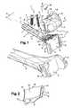
figure 1 est une vue en perspective montrant le matériel prothétique selon l'invention, en deux parties ici dissociées (plaque et platine rapportée), et avec une partie des vis de fixation, positionné au-dessus d'un radius convenablement préparé pour sa réception ; - la
figure 2 est une vue en perspective de la platine rapportée, illustrée ici avec sa face arrière visible, - la
figure 3 est une vue en perspective illustrant le matériel prothétique posé sur l'extrémité distale du radius, avec une partie des vis de fixation pré-positionnées, - la
figure 4 est une vue en perspective similaire à lafigure 3 , avec toutes les vis de fixation mises en place.
- the
figure 1 is a perspective view showing the prosthetic material according to the invention, in two parts here dissociated (plate and plate insert), and with a portion of the fixing screws, positioned above a radius suitably prepared for its reception; - the
figure 2 is a perspective view of the reported plate, illustrated here with its visible rear face, - the
figure 3 is a perspective view illustrating the prosthetic material placed on the distal end of the radius, with part of the pre-positioned fixing screws, - the
figure 4 is a perspective view similar to thefigure 3 , with all the fixing screws put in place.
Le matériel prothétique 1, illustré sur les
Comme on peut le voir sur les
La structure prothétique 1' est en fait ici composée de deux éléments distincts, le premier formé de la plaque 2, munie d'une extension 5 constituant une partie de l'embout 3, et le second formé d'une platine 6 constituant l'autre partie dudit embout 3.The prosthetic structure 1 'is in fact here composed of two distinct elements, the first formed of the
Comme décrit plus loin cette extension 5 et cette platine 6 comportent des moyens qui permettent leur solidarisation.As described later, this
La plaque 2 est composée d'un corps allongé 7, prolongé à l'une de ses extrémités par une tête monobloc 8, elle-même prolongée par l'extension monobloc précitée 5.The
Le corps 7 et la tête 8 de la plaque 2 s'étendent pratiquement dans un même plan P. Ils sont délimités par une face de dessus, respectivement 7' et 8', et par une face de dessous 7" et 8". Ces faces de dessous 7", 8" sont adaptées à l'anatomie de l'extrémité du radius (pour cela, la tête 8 remonte légèrement par rapport au plan dans lequel s'étend le corps de plaque 7).The
Le corps de plaque 7 est traversé par une pluralité d'orifices 9, 9' alignés sur son axeC. L'un de ces orifices 9' est de forme générale oblongue ; il est de préférence positionné dans la partie centrale du corps de plaque 7. Les autres orifices 9, ménagés de part et d'autre de l'orifice oblong 9', ont une forme générale circulaire.The
Les orifices 9, 9' sont destinés à recevoir des vis de fixation 4, dont une seule est représentée sur la
La tête de plaque 8 est également traversée par une pluralité d'orifices 10 (en l'occurrence trois, ici alignés sur sa largeur, c'est-à-dire transversalement à l'axeC du corps de plaque 7).The
Ces orifices 10 sont destinés à recevoir des vis 4' (dont une seule est représentée sur la
L'extension 5 s'étend du côté de la face de dessous 7", 8" du corps de plaque 7 et de la tête de plaque 8, à partir de l'extrémité de ladite tête de plaque 8, ceci selon un planD qui est décalé angulairement par rapport au plan P du corps de plaque 7. Ici, le décalage angulaire correspondant est de l'ordre de 75°.The
Cette extension 5 consiste en un plateau dont la face arrière 5' est disposée du côté des faces de dessous 7" et 8" du corps 7 et de la tête 8 de la plaque 2, et dont la face avant 5" prolonge les faces de dessus 7', 8' dudit corps et de ladite tête de plaque 7, 8.This
Les faces arrière 5' et avant 5" de l'extension 5 sont parallèles et elles s'étendent toutes les deux dans le plan D.The rear faces 5 'and
La face avant 5" de l'extension 5 comporte des moyens qui permettent la réception et la fixation de l'embout 3, ces moyens se présentant sous la forme de deux rails parallèles 11 orientés en regard l'un de l'autre. Ces deux rails 11 s'étendent parallèlement au planD de l'extension 5, et le long des bordures latérales de cette dernière.The
La plaque 2 peut être réalisée en matériau métallique tel que le titane par exemple.The
La platine 6, illustrée isolément sur la
A cet effet, la face arrière 12 de la platine 6 est plane et elle comporte, sur ses côtés, deux nervures parallèles 13 aptes à venir s'insérer par coulissement dans les rails 11 de l'extension 5.For this purpose, the
Les nervures 13 de la platine 6 et les rails 11 de l'extension 5 forment ainsi une structure de glissières qui permet le montage de la platine 6 sur l'extrémité de la plaque 2, selon un axe (ou un plan) ici parallèle au planD.The
Dans la partie supérieure des nervures 13, on remarque la présence de butées 14 qui permettent de bloquer la progression de la platine 6 sur l'extension 5, par contact avec l'extrémité supérieure des rails 11.In the upper part of the
La platine 6 est positionnée sur la plaque 2 par le dessus des rails 11 (c'est-à-dire du côté de la face de dessus 7', 8' du corps de plaque 7 et de la tête de plaque 8).The plate 6 is positioned on the
Les butées 14 bloquent donc la progression de la platine 6 vers le bas, si on tient compte de l'orientation des éléments sur la
Des moyens anti-retour 15, du type activables/désactivables, sont prévus pour assurer le verrouillage complet de la platine 6, une fois celle-ci correctement positionnée sur la plaque 2.Non-return means 15, of the activatable / deactivatable type, are provided to ensure the complete locking of the plate 6, once it is correctly positioned on the
Ces moyens de verrouillage 15 sont prévus ici au niveau de l'extrémité de la tête de plaque 8 ; ils consistent en une vis 16 apte à venir se loger dans un orifice taraudé 17 ménagé dans la tête de plaque 8, et dont une partie de l'extrémité supérieure (tête de vis) est agencée pour venir en butée contre la bordure supérieure de la platine rapportée 6. En l'occurrence, la vis 16 vient en butée contre un ergot 18 qui s'étend en légère saillie à partir de la bordure supérieure de la platine 6, empêchant ainsi, en combinaison avec les butées 14, toute possibilité de mouvement de ladite platine 6 une fois en position.These locking means 15 are provided here at the end of the
Une fois la platine 6 fixée sur l'extension 5, sa face arrière plane 12 est disposée en regard de la face avant plane 5" de l'extension 5, en contact ou pratiquement en contact avec cette dernière.Once the plate 6 fixed on the
L'embout 3 ainsi formé comprend une face avant externe 3' reconstituant la surface de glène radiale réséquée, et une face interne 5' correspondant à la face arrière de l'extension 5, qui s'étend dans le planD.The
La platine 6 peut être réalisée en tout matériau biocompatible, par exemple en chrome-cobalt, peek, polyéthylène ou pyrocarbone.The plate 6 may be made of any biocompatible material, for example cobalt chrome, peek, polyethylene or pyrocarbon.
De préférence, en association avec la plaque 2, il est prévu un jeu de platines 6 d'épaisseurs différentes, mis à la disposition du chirurgien, de manière à lui proposer un choix de prothèses, en fonction de la profondeur de résection qu'il est amené à réaliser dans l'os.Preferably, in association with the
Le matériel prothétique selon l'invention trouve une application particulièrement intéressante dans le cas d'une fracture de l'extrémité distale du radius, accompagnée de lésions de la surface articulaire (au niveau de la glène radiale).The prosthetic material according to the invention finds a particularly advantageous application in the case of a fracture of the distal end of the radius, accompanied by lesions of the articular surface (at the level of the radial glenoid).
Le chirurgien peut alors utiliser avantageusement une technique opératoire par voie palmaire.The surgeon can then advantageously use a palmar surgical technique.
Pour cela, après ouverture au niveau du poignet du patient, le praticien réalise la résection de la glène radiale abimée, ainsi qu'une réduction manuelle de la fracture osseuse. Ensuite, il positionne convenablement la plaque 2 sur la corticale antérieure du radius, avec l'extension 5 et la platine 6 associée, dans la réservation Z (
Plus précisément, dans un premier temps, la plaque 2, sans la platine 6, peut être prépositionnée sur le radius en utilisant simplement une vis centrale 4 logée dans l'orifice oblong 9'. Par suivi sous amplificateur de brillance, cela permet au chirurgien de tester différentes platines 6, d'ajuster la position de la plaque 2 sur le radius et de réduire temporairement la fracture au moyen de broches.More specifically, in a first step, the
Lorsque le choix du positionnement de la plaque 2 est réalisé, le chirurgien la fixe correctement au moyen des vis 4 dans les orifices 9 du corps de plaque 7 et au moyen des vis 4' dans les orifices 10 de la tête de plaque 8 (
Le chirurgien peut ensuite terminer l'opération en effectuant la balance ligamentaire, puis en positionnant la platine 6 définitive sur l'extension de plaque 5, avant de refermer le champ opératoire.The surgeon can then complete the operation by performing the ligament balance, then positioning the final plate 6 on the
Dans une variante de réalisation, la plaque 2 peut être réalisée en plusieurs parties munies de moyens d'assemblage entre elles.In an alternative embodiment, the
Claims (10)
- Prosthetic material for replacing at least one portion of the radial glenoid of a radius (R), which material comprises:- a prosthetic structure (1') constituted by a plate (2) extended by an endpiece (3), said plate (2) being made up of a planar body (7) extended by a one-piece head (8), and said plate (2) including a top face (7', 8') and a bottom face (7", 8"), and being provided with through orifices (9, 9', 10), said plate head (8) itself being extended by said endpiece (3), and- a set of screws (4, 4') for co-operating with said through orifices (9, 9', 10) of said plate (2) to fasten said prosthetic structure (1') to the receiving bony material (R) after resection of the portion of the radial glenoid that it is desired to replace and after positioning the bottom face (7", 8") of said plate (2) against the cortex of said bone material (R),said endpiece (3) being constituted by - a support extension (5) made as one piece with said plate head (8) and having an inner face (5') extending in a general plane (D) that is offset angularly relative to the plane (P) of said plate body (7), and by - a fitted articular panel (6) having an outer surface (3') that is situated extending the top face (7', 8') of said plate (2) and reproducing at least approximately at least a portion of the surface of the radial glenoid of the radius, which support extension (5) and fitted panel (6) are provided with means (11, 13, 14, 15) enabling them to be secured to each other, which securing means comprise means (14, 15) for fastening said fitted panel (6) in the correct position on said extension (5),
the material beingcharacterized in that said securing means comprise too a slideway structure (11, 13) arranged in part on the rear face and/or on the sides of said panel (6), and also in part on the front face (5") and/or on the sides of said extension (5). - Material according to claim 1,characterized in that the inner face (5') of the support extension (5) extends in a general plane D that is offset at an angle lying in the range 60° to 80° relative to the plane P of the plate body (7).
- Material according to any one of claims 1 or 2,characterized in that the plane of movement in translation of the slideway structure (11, 13) lies in a plane parallel to said plane (D).
- Material according to any one of claims 1 to 3,characterized in that the plate extension (5) has two parallel side rails (11) facing each other and suitable for co-operating with two parallel ribs (13) arranged on the sides of said fitted panel (6).
- Material according to claim 4,characterized in that said means for fastening the panel (6) in the correct position on the extension (5) comprise abutments (14) formed at one of the ends of the ribs (13) of said fitted panel (6).
- Material according to any one of claims 4 or 5,characterized in that said means for fastening the panel (6) in the correct position on the extension (5) comprise locking means (15) of the activatable/deactivatable type that prevent any movement of the fitted panel (6) once it is in place on the plate (2).
- Material according to claim 6,characterized in that said locking means (15) consist of a screw (16) that is received in a tapped orifice (17) formed in the plate head (8) and having a top end portion that comes into abutment against the top end of the fitted panel (6).
- Material according to any one of claims 1 to 7,characterized in that the plate (2) of the prosthetic structure (1') is arranged to be positioned against the anterior cortex of the radius (R).
- Material according to any one of claims 1 to 8,characterized in that at least some of the screws (4') of the plate head (8) are of a length that is adapted for reaching the opposite cortex of the radius (R) so as to enable a bone reduction to be held.
- Material according to any one of claims 1 to 9,characterized in that the width of the endpiece (3) is less than the width of the radial glenoid, andin that said endpiece (3) is arranged to be positioned in a reception zone (Z) arranged in the central portion of said radial glenoid, between the radial styloid and the radioulnar joint.
Applications Claiming Priority (2)
| Application Number | Priority Date | Filing Date | Title |
|---|---|---|---|
| FR0905043AFR2951366B1 (en) | 2009-10-21 | 2009-10-21 | PROSTHETIC EQUIPMENT FOR REPLACING AT LEAST ONE PART OF THE RADIAL RADIUS GLENES |
| PCT/FR2010/052236WO2011048331A1 (en) | 2009-10-21 | 2010-10-20 | Prosthetic material for replacing at least one portion of the radial glenoid of a radius |
Publications (2)
| Publication Number | Publication Date |
|---|---|
| EP2490610A1 EP2490610A1 (en) | 2012-08-29 |
| EP2490610B1true EP2490610B1 (en) | 2014-06-25 |
Family
ID=42044762
Family Applications (1)
| Application Number | Title | Priority Date | Filing Date |
|---|---|---|---|
| EP10785147.9AActiveEP2490610B1 (en) | 2009-10-21 | 2010-10-20 | Prosthetic material for replacing at least one portion of the radial glenoid of a radius |
Country Status (4)
| Country | Link |
|---|---|
| US (1) | US8597363B2 (en) |
| EP (1) | EP2490610B1 (en) |
| FR (1) | FR2951366B1 (en) |
| WO (1) | WO2011048331A1 (en) |
Families Citing this family (9)
| Publication number | Priority date | Publication date | Assignee | Title |
|---|---|---|---|---|
| US8961573B2 (en) | 2010-10-05 | 2015-02-24 | Toby Orthopaedics, Inc. | System and method for facilitating repair and reattachment of comminuted bone portions |
| WO2012058448A2 (en) | 2010-10-27 | 2012-05-03 | Toby Orthopaedics, Llc | System and method for fracture replacement of comminuted bone fractures or portions thereof adjacent bone joints |
| WO2012119146A2 (en) | 2011-03-03 | 2012-09-07 | Toby Orthopaedics, Llc | Anterior lesser tuberosity fixed angle fixation device and method of use associated therewith |
| US9271772B2 (en) | 2011-10-27 | 2016-03-01 | Toby Orthopaedics, Inc. | System and method for fracture replacement of comminuted bone fractures or portions thereof adjacent bone joints |
| US9730797B2 (en)* | 2011-10-27 | 2017-08-15 | Toby Orthopaedics, Inc. | Bone joint replacement and repair assembly and method of repairing and replacing a bone joint |
| US9402667B2 (en) | 2011-11-09 | 2016-08-02 | Eduardo Gonzalez-Hernandez | Apparatus and method for use of the apparatus for fracture fixation of the distal humerus |
| US9283008B2 (en) | 2012-12-17 | 2016-03-15 | Toby Orthopaedics, Inc. | Bone plate for plate osteosynthesis and method for use thereof |
| US9333014B2 (en) | 2013-03-15 | 2016-05-10 | Eduardo Gonzalez-Hernandez | Bone fixation and reduction apparatus and method for fixation and reduction of a distal bone fracture and malunion |
| CN103230311B (en)* | 2013-05-06 | 2015-12-23 | 北京爱康宜诚医疗器材股份有限公司 | Combination type shoulder joint prosthesis |
Family Cites Families (6)
| Publication number | Priority date | Publication date | Assignee | Title |
|---|---|---|---|---|
| US5522902A (en)* | 1994-03-09 | 1996-06-04 | Yuan; Hansen A. | Femoral component used in artificial knee joint |
| US8821581B2 (en)* | 2002-10-24 | 2014-09-02 | Biomet Manufacturing, Llc | Method and apparatus for wrist arthroplasty |
| US7270679B2 (en)* | 2003-05-30 | 2007-09-18 | Warsaw Orthopedic, Inc. | Implants based on engineered metal matrix composite materials having enhanced imaging and wear resistance |
| US8052757B1 (en)* | 2005-10-13 | 2011-11-08 | Aptis Medical, Llc | Combined total wrist and total distal radioulnar joint prosthesis |
| US7601175B2 (en)* | 2006-03-14 | 2009-10-13 | Synthes Usa, Llc | Condylar head add-on system |
| US9278006B2 (en)* | 2006-10-26 | 2016-03-08 | European Foot Platform Sc | Ankle prosthesis with neutral position adjustment |
- 2009
- 2009-10-21FRFR0905043Apatent/FR2951366B1/ennot_activeExpired - Fee Related
- 2010
- 2010-10-20EPEP10785147.9Apatent/EP2490610B1/enactiveActive
- 2010-10-20WOPCT/FR2010/052236patent/WO2011048331A1/enactiveApplication Filing
- 2010-10-20USUS13/501,202patent/US8597363B2/enactiveActive
Also Published As
| Publication number | Publication date |
|---|---|
| EP2490610A1 (en) | 2012-08-29 |
| US20120203349A1 (en) | 2012-08-09 |
| FR2951366B1 (en) | 2012-04-27 |
| FR2951366A1 (en) | 2011-04-22 |
| US8597363B2 (en) | 2013-12-03 |
| WO2011048331A1 (en) | 2011-04-28 |
Similar Documents
| Publication | Publication Date | Title |
|---|---|---|
| EP2490610B1 (en) | Prosthetic material for replacing at least one portion of the radial glenoid of a radius | |
| EP3687455B1 (en) | Ankle prosthesis comprising a talar implant, a tibial implant and an insert, and kit including at least one such prosthesis | |
| EP2243444B1 (en) | Device for fixation of a joint cup for a shoulder prosthesis and corresponding shoulder prosthesis | |
| EP2385813B1 (en) | Orthopaedic implant for arthroplasty of the fingers | |
| EP1025819B1 (en) | Knee prosthesis with an insert, which is mobile in relation to a post | |
| EP1317911B1 (en) | Elbow prosthesis | |
| EP2547291B1 (en) | Knee prosthesis having a mixed meniscal plate | |
| EP1872731B1 (en) | Implant intended for stabilising the lumbo-sacral region | |
| EP2385812B1 (en) | Intramedullary anchoring stem for an orthopaedic implant head | |
| FR3132204A1 (en) | IMPROVED ANKLE PROSTHESIS | |
| FR2570594A1 (en) | VERTEBRAL PROSTHESIS, ESPECIALLY FOR CERVICAL VERTEBRATES | |
| FR2727003A1 (en) | Lumbar-sacral vertebrae anterior stabiliser | |
| EP1094759A1 (en) | Backbone osteosynthesis device for anterior fixing with plate | |
| FR2879436A1 (en) | INTERVERTEBRAL DISC PROSTHESIS | |
| EP2277460A1 (en) | Surgical instrumentation for preparing the setting of a knee prosthesis | |
| WO1999055247A1 (en) | Backbone osteosynthesis system with clamping means in particular for anterior fixing | |
| WO1995014446A1 (en) | Total knee prosthesis and associated modular knee prosthesis assembly | |
| FR2780636A1 (en) | Modular knee prosthesis comprises lower femoral mounting plate and upper tibial plate for total knee prosthesis | |
| FR2773059A1 (en) | KNEE PROSTHESIS | |
| FR2955248A1 (en) | Shoulder prosthesis glenoidal component for use on coil of scapula, has fixation base provided with anchoring unit, and plate defining articular surface on plate opposed face, where articular surface cooperates with humeral head | |
| WO2009092907A2 (en) | Intervertebral disc prosthesis | |
| EP1719477A1 (en) | Shoulder prosthesis | |
| EP0639360A1 (en) | Finger articulation prosthesis with one dish shaped element | |
| FR2630640A1 (en) | Partial knee prosthesis device | |
| FR2684291A1 (en) | Ankle prosthesis |
Legal Events
| Date | Code | Title | Description |
|---|---|---|---|
| PUAI | Public reference made under article 153(3) epc to a published international application that has entered the european phase | Free format text:ORIGINAL CODE: 0009012 | |
| 17P | Request for examination filed | Effective date:20120418 | |
| AK | Designated contracting states | Kind code of ref document:A1 Designated state(s):AL AT BE BG CH CY CZ DE DK EE ES FI FR GB GR HR HU IE IS IT LI LT LU LV MC MK MT NL NO PL PT RO RS SE SI SK SM TR | |
| DAX | Request for extension of the european patent (deleted) | ||
| GRAP | Despatch of communication of intention to grant a patent | Free format text:ORIGINAL CODE: EPIDOSNIGR1 | |
| INTG | Intention to grant announced | Effective date:20131217 | |
| GRAS | Grant fee paid | Free format text:ORIGINAL CODE: EPIDOSNIGR3 | |
| GRAA | (expected) grant | Free format text:ORIGINAL CODE: 0009210 | |
| AK | Designated contracting states | Kind code of ref document:B1 Designated state(s):AL AT BE BG CH CY CZ DE DK EE ES FI FR GB GR HR HU IE IS IT LI LT LU LV MC MK MT NL NO PL PT RO RS SE SI SK SM TR | |
| RAP1 | Party data changed (applicant data changed or rights of an application transferred) | Owner name:D.L.P. | |
| REG | Reference to a national code | Ref country code:GB Ref legal event code:FG4D Free format text:NOT ENGLISH | |
| REG | Reference to a national code | Ref country code:CH Ref legal event code:EP | |
| REG | Reference to a national code | Ref country code:AT Ref legal event code:REF Ref document number:674099 Country of ref document:AT Kind code of ref document:T Effective date:20140715 | |
| REG | Reference to a national code | Ref country code:IE Ref legal event code:FG4D Free format text:LANGUAGE OF EP DOCUMENT: FRENCH | |
| REG | Reference to a national code | Ref country code:DE Ref legal event code:R096 Ref document number:602010017067 Country of ref document:DE Effective date:20140807 | |
| PG25 | Lapsed in a contracting state [announced via postgrant information from national office to epo] | Ref country code:GR Free format text:LAPSE BECAUSE OF FAILURE TO SUBMIT A TRANSLATION OF THE DESCRIPTION OR TO PAY THE FEE WITHIN THE PRESCRIBED TIME-LIMIT Effective date:20140926 Ref country code:NO Free format text:LAPSE BECAUSE OF FAILURE TO SUBMIT A TRANSLATION OF THE DESCRIPTION OR TO PAY THE FEE WITHIN THE PRESCRIBED TIME-LIMIT Effective date:20140925 Ref country code:LT Free format text:LAPSE BECAUSE OF FAILURE TO SUBMIT A TRANSLATION OF THE DESCRIPTION OR TO PAY THE FEE WITHIN THE PRESCRIBED TIME-LIMIT Effective date:20140625 Ref country code:FI Free format text:LAPSE BECAUSE OF FAILURE TO SUBMIT A TRANSLATION OF THE DESCRIPTION OR TO PAY THE FEE WITHIN THE PRESCRIBED TIME-LIMIT Effective date:20140625 Ref country code:CY Free format text:LAPSE BECAUSE OF FAILURE TO SUBMIT A TRANSLATION OF THE DESCRIPTION OR TO PAY THE FEE WITHIN THE PRESCRIBED TIME-LIMIT Effective date:20140625 | |
| REG | Reference to a national code | Ref country code:AT Ref legal event code:MK05 Ref document number:674099 Country of ref document:AT Kind code of ref document:T Effective date:20140625 | |
| REG | Reference to a national code | Ref country code:NL Ref legal event code:VDEP Effective date:20140625 | |
| REG | Reference to a national code | Ref country code:LT Ref legal event code:MG4D | |
| PG25 | Lapsed in a contracting state [announced via postgrant information from national office to epo] | Ref country code:RS Free format text:LAPSE BECAUSE OF FAILURE TO SUBMIT A TRANSLATION OF THE DESCRIPTION OR TO PAY THE FEE WITHIN THE PRESCRIBED TIME-LIMIT Effective date:20140625 Ref country code:LV Free format text:LAPSE BECAUSE OF FAILURE TO SUBMIT A TRANSLATION OF THE DESCRIPTION OR TO PAY THE FEE WITHIN THE PRESCRIBED TIME-LIMIT Effective date:20140625 Ref country code:HR Free format text:LAPSE BECAUSE OF FAILURE TO SUBMIT A TRANSLATION OF THE DESCRIPTION OR TO PAY THE FEE WITHIN THE PRESCRIBED TIME-LIMIT Effective date:20140625 Ref country code:SE Free format text:LAPSE BECAUSE OF FAILURE TO SUBMIT A TRANSLATION OF THE DESCRIPTION OR TO PAY THE FEE WITHIN THE PRESCRIBED TIME-LIMIT Effective date:20140625 | |
| PG25 | Lapsed in a contracting state [announced via postgrant information from national office to epo] | Ref country code:SK Free format text:LAPSE BECAUSE OF FAILURE TO SUBMIT A TRANSLATION OF THE DESCRIPTION OR TO PAY THE FEE WITHIN THE PRESCRIBED TIME-LIMIT Effective date:20140625 Ref country code:PT Free format text:LAPSE BECAUSE OF FAILURE TO SUBMIT A TRANSLATION OF THE DESCRIPTION OR TO PAY THE FEE WITHIN THE PRESCRIBED TIME-LIMIT Effective date:20141027 Ref country code:CZ Free format text:LAPSE BECAUSE OF FAILURE TO SUBMIT A TRANSLATION OF THE DESCRIPTION OR TO PAY THE FEE WITHIN THE PRESCRIBED TIME-LIMIT Effective date:20140625 Ref country code:EE Free format text:LAPSE BECAUSE OF FAILURE TO SUBMIT A TRANSLATION OF THE DESCRIPTION OR TO PAY THE FEE WITHIN THE PRESCRIBED TIME-LIMIT Effective date:20140625 Ref country code:RO Free format text:LAPSE BECAUSE OF FAILURE TO SUBMIT A TRANSLATION OF THE DESCRIPTION OR TO PAY THE FEE WITHIN THE PRESCRIBED TIME-LIMIT Effective date:20140625 Ref country code:ES Free format text:LAPSE BECAUSE OF FAILURE TO SUBMIT A TRANSLATION OF THE DESCRIPTION OR TO PAY THE FEE WITHIN THE PRESCRIBED TIME-LIMIT Effective date:20140625 | |
| PG25 | Lapsed in a contracting state [announced via postgrant information from national office to epo] | Ref country code:NL Free format text:LAPSE BECAUSE OF FAILURE TO SUBMIT A TRANSLATION OF THE DESCRIPTION OR TO PAY THE FEE WITHIN THE PRESCRIBED TIME-LIMIT Effective date:20140625 Ref country code:IS Free format text:LAPSE BECAUSE OF FAILURE TO SUBMIT A TRANSLATION OF THE DESCRIPTION OR TO PAY THE FEE WITHIN THE PRESCRIBED TIME-LIMIT Effective date:20141025 Ref country code:AT Free format text:LAPSE BECAUSE OF FAILURE TO SUBMIT A TRANSLATION OF THE DESCRIPTION OR TO PAY THE FEE WITHIN THE PRESCRIBED TIME-LIMIT Effective date:20140625 Ref country code:PL Free format text:LAPSE BECAUSE OF FAILURE TO SUBMIT A TRANSLATION OF THE DESCRIPTION OR TO PAY THE FEE WITHIN THE PRESCRIBED TIME-LIMIT Effective date:20140625 | |
| REG | Reference to a national code | Ref country code:DE Ref legal event code:R097 Ref document number:602010017067 Country of ref document:DE | |
| PG25 | Lapsed in a contracting state [announced via postgrant information from national office to epo] | Ref country code:IT Free format text:LAPSE BECAUSE OF FAILURE TO SUBMIT A TRANSLATION OF THE DESCRIPTION OR TO PAY THE FEE WITHIN THE PRESCRIBED TIME-LIMIT Effective date:20140625 Ref country code:DK Free format text:LAPSE BECAUSE OF FAILURE TO SUBMIT A TRANSLATION OF THE DESCRIPTION OR TO PAY THE FEE WITHIN THE PRESCRIBED TIME-LIMIT Effective date:20140625 | |
| PLBE | No opposition filed within time limit | Free format text:ORIGINAL CODE: 0009261 | |
| REG | Reference to a national code | Ref country code:DE Ref legal event code:R119 Ref document number:602010017067 Country of ref document:DE | |
| STAA | Information on the status of an ep patent application or granted ep patent | Free format text:STATUS: NO OPPOSITION FILED WITHIN TIME LIMIT | |
| PG25 | Lapsed in a contracting state [announced via postgrant information from national office to epo] | Ref country code:LU Free format text:LAPSE BECAUSE OF FAILURE TO SUBMIT A TRANSLATION OF THE DESCRIPTION OR TO PAY THE FEE WITHIN THE PRESCRIBED TIME-LIMIT Effective date:20141020 Ref country code:MC Free format text:LAPSE BECAUSE OF FAILURE TO SUBMIT A TRANSLATION OF THE DESCRIPTION OR TO PAY THE FEE WITHIN THE PRESCRIBED TIME-LIMIT Effective date:20140625 | |
| REG | Reference to a national code | Ref country code:CH Ref legal event code:PL | |
| 26N | No opposition filed | Effective date:20150326 | |
| GBPC | Gb: european patent ceased through non-payment of renewal fee | Effective date:20141020 | |
| PG25 | Lapsed in a contracting state [announced via postgrant information from national office to epo] | Ref country code:BE Free format text:LAPSE BECAUSE OF NON-PAYMENT OF DUE FEES Effective date:20141031 | |
| REG | Reference to a national code | Ref country code:DE Ref legal event code:R097 Ref document number:602010017067 Country of ref document:DE Effective date:20150326 | |
| REG | Reference to a national code | Ref country code:IE Ref legal event code:MM4A | |
| PG25 | Lapsed in a contracting state [announced via postgrant information from national office to epo] | Ref country code:GB Free format text:LAPSE BECAUSE OF NON-PAYMENT OF DUE FEES Effective date:20141020 Ref country code:CH Free format text:LAPSE BECAUSE OF NON-PAYMENT OF DUE FEES Effective date:20141031 Ref country code:LI Free format text:LAPSE BECAUSE OF NON-PAYMENT OF DUE FEES Effective date:20141031 Ref country code:DE Free format text:LAPSE BECAUSE OF NON-PAYMENT OF DUE FEES Effective date:20150501 | |
| PG25 | Lapsed in a contracting state [announced via postgrant information from national office to epo] | Ref country code:IE Free format text:LAPSE BECAUSE OF NON-PAYMENT OF DUE FEES Effective date:20141020 | |
| PG25 | Lapsed in a contracting state [announced via postgrant information from national office to epo] | Ref country code:SI Free format text:LAPSE BECAUSE OF FAILURE TO SUBMIT A TRANSLATION OF THE DESCRIPTION OR TO PAY THE FEE WITHIN THE PRESCRIBED TIME-LIMIT Effective date:20140625 | |
| PG25 | Lapsed in a contracting state [announced via postgrant information from national office to epo] | Ref country code:SM Free format text:LAPSE BECAUSE OF FAILURE TO SUBMIT A TRANSLATION OF THE DESCRIPTION OR TO PAY THE FEE WITHIN THE PRESCRIBED TIME-LIMIT Effective date:20140625 | |
| PG25 | Lapsed in a contracting state [announced via postgrant information from national office to epo] | Ref country code:BG Free format text:LAPSE BECAUSE OF FAILURE TO SUBMIT A TRANSLATION OF THE DESCRIPTION OR TO PAY THE FEE WITHIN THE PRESCRIBED TIME-LIMIT Effective date:20140625 | |
| PG25 | Lapsed in a contracting state [announced via postgrant information from national office to epo] | Ref country code:HU Free format text:LAPSE BECAUSE OF FAILURE TO SUBMIT A TRANSLATION OF THE DESCRIPTION OR TO PAY THE FEE WITHIN THE PRESCRIBED TIME-LIMIT; INVALID AB INITIO Effective date:20101020 Ref country code:MT Free format text:LAPSE BECAUSE OF FAILURE TO SUBMIT A TRANSLATION OF THE DESCRIPTION OR TO PAY THE FEE WITHIN THE PRESCRIBED TIME-LIMIT Effective date:20140625 Ref country code:TR Free format text:LAPSE BECAUSE OF FAILURE TO SUBMIT A TRANSLATION OF THE DESCRIPTION OR TO PAY THE FEE WITHIN THE PRESCRIBED TIME-LIMIT Effective date:20140625 | |
| REG | Reference to a national code | Ref country code:FR Ref legal event code:PLFP Year of fee payment:7 | |
| REG | Reference to a national code | Ref country code:FR Ref legal event code:PLFP Year of fee payment:8 | |
| PG25 | Lapsed in a contracting state [announced via postgrant information from national office to epo] | Ref country code:MK Free format text:LAPSE BECAUSE OF FAILURE TO SUBMIT A TRANSLATION OF THE DESCRIPTION OR TO PAY THE FEE WITHIN THE PRESCRIBED TIME-LIMIT Effective date:20140625 | |
| REG | Reference to a national code | Ref country code:FR Ref legal event code:PLFP Year of fee payment:9 | |
| PG25 | Lapsed in a contracting state [announced via postgrant information from national office to epo] | Ref country code:AL Free format text:LAPSE BECAUSE OF FAILURE TO SUBMIT A TRANSLATION OF THE DESCRIPTION OR TO PAY THE FEE WITHIN THE PRESCRIBED TIME-LIMIT Effective date:20140625 | |
| P01 | Opt-out of the competence of the unified patent court (upc) registered | Effective date:20230514 | |
| PGFP | Annual fee paid to national office [announced via postgrant information from national office to epo] | Ref country code:FR Payment date:20240905 Year of fee payment:15 |