EP2489337B1 - Prosthesis and method of manufacture - Google Patents
Prosthesis and method of manufactureDownload PDFInfo
- Publication number
- EP2489337B1 EP2489337B1EP12275017.7AEP12275017AEP2489337B1EP 2489337 B1EP2489337 B1EP 2489337B1EP 12275017 AEP12275017 AEP 12275017AEP 2489337 B1EP2489337 B1EP 2489337B1
- Authority
- EP
- European Patent Office
- Prior art keywords
- prosthesis
- stent
- apexes
- stent member
- adjacent
- Prior art date
- Legal status (The legal status is an assumption and is not a legal conclusion. Google has not performed a legal analysis and makes no representation as to the accuracy of the status listed.)
- Active
Links
Images


Classifications
- A—HUMAN NECESSITIES
- A61—MEDICAL OR VETERINARY SCIENCE; HYGIENE
- A61F—FILTERS IMPLANTABLE INTO BLOOD VESSELS; PROSTHESES; DEVICES PROVIDING PATENCY TO, OR PREVENTING COLLAPSING OF, TUBULAR STRUCTURES OF THE BODY, e.g. STENTS; ORTHOPAEDIC, NURSING OR CONTRACEPTIVE DEVICES; FOMENTATION; TREATMENT OR PROTECTION OF EYES OR EARS; BANDAGES, DRESSINGS OR ABSORBENT PADS; FIRST-AID KITS
- A61F2/00—Filters implantable into blood vessels; Prostheses, i.e. artificial substitutes or replacements for parts of the body; Appliances for connecting them with the body; Devices providing patency to, or preventing collapsing of, tubular structures of the body, e.g. stents
- A61F2/82—Devices providing patency to, or preventing collapsing of, tubular structures of the body, e.g. stents
- A61F2/86—Stents in a form characterised by the wire-like elements; Stents in the form characterised by a net-like or mesh-like structure
- A61F2/90—Stents in a form characterised by the wire-like elements; Stents in the form characterised by a net-like or mesh-like structure characterised by a net-like or mesh-like structure
- A61F2/91—Stents in a form characterised by the wire-like elements; Stents in the form characterised by a net-like or mesh-like structure characterised by a net-like or mesh-like structure made from perforated sheets or tubes, e.g. perforated by laser cuts or etched holes
- A61F2/915—Stents in a form characterised by the wire-like elements; Stents in the form characterised by a net-like or mesh-like structure characterised by a net-like or mesh-like structure made from perforated sheets or tubes, e.g. perforated by laser cuts or etched holes with bands having a meander structure, adjacent bands being connected to each other
- A—HUMAN NECESSITIES
- A61—MEDICAL OR VETERINARY SCIENCE; HYGIENE
- A61F—FILTERS IMPLANTABLE INTO BLOOD VESSELS; PROSTHESES; DEVICES PROVIDING PATENCY TO, OR PREVENTING COLLAPSING OF, TUBULAR STRUCTURES OF THE BODY, e.g. STENTS; ORTHOPAEDIC, NURSING OR CONTRACEPTIVE DEVICES; FOMENTATION; TREATMENT OR PROTECTION OF EYES OR EARS; BANDAGES, DRESSINGS OR ABSORBENT PADS; FIRST-AID KITS
- A61F2/00—Filters implantable into blood vessels; Prostheses, i.e. artificial substitutes or replacements for parts of the body; Appliances for connecting them with the body; Devices providing patency to, or preventing collapsing of, tubular structures of the body, e.g. stents
- A61F2/82—Devices providing patency to, or preventing collapsing of, tubular structures of the body, e.g. stents
- A61F2002/825—Devices providing patency to, or preventing collapsing of, tubular structures of the body, e.g. stents having longitudinal struts
- A—HUMAN NECESSITIES
- A61—MEDICAL OR VETERINARY SCIENCE; HYGIENE
- A61F—FILTERS IMPLANTABLE INTO BLOOD VESSELS; PROSTHESES; DEVICES PROVIDING PATENCY TO, OR PREVENTING COLLAPSING OF, TUBULAR STRUCTURES OF THE BODY, e.g. STENTS; ORTHOPAEDIC, NURSING OR CONTRACEPTIVE DEVICES; FOMENTATION; TREATMENT OR PROTECTION OF EYES OR EARS; BANDAGES, DRESSINGS OR ABSORBENT PADS; FIRST-AID KITS
- A61F2/00—Filters implantable into blood vessels; Prostheses, i.e. artificial substitutes or replacements for parts of the body; Appliances for connecting them with the body; Devices providing patency to, or preventing collapsing of, tubular structures of the body, e.g. stents
- A61F2/82—Devices providing patency to, or preventing collapsing of, tubular structures of the body, e.g. stents
- A61F2002/826—Devices providing patency to, or preventing collapsing of, tubular structures of the body, e.g. stents more than one stent being applied sequentially
- A—HUMAN NECESSITIES
- A61—MEDICAL OR VETERINARY SCIENCE; HYGIENE
- A61F—FILTERS IMPLANTABLE INTO BLOOD VESSELS; PROSTHESES; DEVICES PROVIDING PATENCY TO, OR PREVENTING COLLAPSING OF, TUBULAR STRUCTURES OF THE BODY, e.g. STENTS; ORTHOPAEDIC, NURSING OR CONTRACEPTIVE DEVICES; FOMENTATION; TREATMENT OR PROTECTION OF EYES OR EARS; BANDAGES, DRESSINGS OR ABSORBENT PADS; FIRST-AID KITS
- A61F2/00—Filters implantable into blood vessels; Prostheses, i.e. artificial substitutes or replacements for parts of the body; Appliances for connecting them with the body; Devices providing patency to, or preventing collapsing of, tubular structures of the body, e.g. stents
- A61F2/82—Devices providing patency to, or preventing collapsing of, tubular structures of the body, e.g. stents
- A61F2/86—Stents in a form characterised by the wire-like elements; Stents in the form characterised by a net-like or mesh-like structure
- A61F2/90—Stents in a form characterised by the wire-like elements; Stents in the form characterised by a net-like or mesh-like structure characterised by a net-like or mesh-like structure
- A61F2/91—Stents in a form characterised by the wire-like elements; Stents in the form characterised by a net-like or mesh-like structure characterised by a net-like or mesh-like structure made from perforated sheets or tubes, e.g. perforated by laser cuts or etched holes
- A61F2/915—Stents in a form characterised by the wire-like elements; Stents in the form characterised by a net-like or mesh-like structure characterised by a net-like or mesh-like structure made from perforated sheets or tubes, e.g. perforated by laser cuts or etched holes with bands having a meander structure, adjacent bands being connected to each other
- A61F2002/91533—Stents in a form characterised by the wire-like elements; Stents in the form characterised by a net-like or mesh-like structure characterised by a net-like or mesh-like structure made from perforated sheets or tubes, e.g. perforated by laser cuts or etched holes with bands having a meander structure, adjacent bands being connected to each other characterised by the phase between adjacent bands
- A—HUMAN NECESSITIES
- A61—MEDICAL OR VETERINARY SCIENCE; HYGIENE
- A61F—FILTERS IMPLANTABLE INTO BLOOD VESSELS; PROSTHESES; DEVICES PROVIDING PATENCY TO, OR PREVENTING COLLAPSING OF, TUBULAR STRUCTURES OF THE BODY, e.g. STENTS; ORTHOPAEDIC, NURSING OR CONTRACEPTIVE DEVICES; FOMENTATION; TREATMENT OR PROTECTION OF EYES OR EARS; BANDAGES, DRESSINGS OR ABSORBENT PADS; FIRST-AID KITS
- A61F2/00—Filters implantable into blood vessels; Prostheses, i.e. artificial substitutes or replacements for parts of the body; Appliances for connecting them with the body; Devices providing patency to, or preventing collapsing of, tubular structures of the body, e.g. stents
- A61F2/82—Devices providing patency to, or preventing collapsing of, tubular structures of the body, e.g. stents
- A61F2/86—Stents in a form characterised by the wire-like elements; Stents in the form characterised by a net-like or mesh-like structure
- A61F2/90—Stents in a form characterised by the wire-like elements; Stents in the form characterised by a net-like or mesh-like structure characterised by a net-like or mesh-like structure
- A61F2/91—Stents in a form characterised by the wire-like elements; Stents in the form characterised by a net-like or mesh-like structure characterised by a net-like or mesh-like structure made from perforated sheets or tubes, e.g. perforated by laser cuts or etched holes
- A61F2/915—Stents in a form characterised by the wire-like elements; Stents in the form characterised by a net-like or mesh-like structure characterised by a net-like or mesh-like structure made from perforated sheets or tubes, e.g. perforated by laser cuts or etched holes with bands having a meander structure, adjacent bands being connected to each other
- A61F2002/9155—Adjacent bands being connected to each other
- A61F2002/91575—Adjacent bands being connected to each other connected peak to trough
- Y—GENERAL TAGGING OF NEW TECHNOLOGICAL DEVELOPMENTS; GENERAL TAGGING OF CROSS-SECTIONAL TECHNOLOGIES SPANNING OVER SEVERAL SECTIONS OF THE IPC; TECHNICAL SUBJECTS COVERED BY FORMER USPC CROSS-REFERENCE ART COLLECTIONS [XRACs] AND DIGESTS
- Y10—TECHNICAL SUBJECTS COVERED BY FORMER USPC
- Y10T—TECHNICAL SUBJECTS COVERED BY FORMER US CLASSIFICATION
- Y10T29/00—Metal working
- Y10T29/49—Method of mechanical manufacture
- Y10T29/49826—Assembling or joining
Definitions
- the present inventionrelates to a generally tubular prosthesis, in particular to a prosthesis comprising a plurality of stents and to a method of manufacturing such a prosthesis.
- Prostheseshave been used for many years to treat a number of vascular medical conditions.
- Prostheses in common usecomprise at least one stent and are either of the self-expandable type, made for example of a shape memory material, or separately expandable, such as by balloon expansion.
- Such prosthesesare designed to fit within the vasculature of the patient and need to be appropriate for the size and shape of the lumen. For this purpose, they must be conformable and must not be of a nature that they can apply against the vessel walls forces which could damage or adversely affect the functionality of the vessel or of other organs nearby.
- such prostheseshave a small cross-sectional diameter and/or profile for introducing the prosthesis into the affected body lumen.
- a configuration which is extremely suited for implantation in a body lumenis a generally cylindrical prosthesis which can radially expand from a first, small, collapsed diameter to a second, larger, expanded diameter.
- Such prosthesescan be deployed in a body lumen at the desired location by means of an introducer assembly, whereby the prosthesis is placed on a catheter and transported through the lumen to the desired location. The prosthesis is retained in a compressed condition by a sheath. Once the introducer assembly has been transported to the desired deployment position the sheath is withdrawn, thus releasing the prosthesis so that
- the prosthesismay be self-expanding or the catheter may be provided with a balloon or another expansion mechanism which exerts a radial outward pressure on the prosthesis so that the prosthesis expands to a larger diameter.
- Lateral deflection in such prosthesescan occur during deployment, such as when the prosthesis is longitudinally compressed as it is maneuvered into the desired location in a patient's lumen.
- Such lateral deflectioncan be problematic during deployment of the prosthesis. For example, this can distort the sheath to cause increased friction between the sheath and the lumen wall, thus hindering deployment. This may particularly be the case when the prosthesis is to be deployed in a curved lumen, such as the aortic arch, and in extreme cases lateral deflection can prevent the prosthesis from being located in the desired position. Further, such lateral deflection can be dangerous for the patient in more delicate applications, such as in smaller and more delicate vessels including, for instance, cerebral vessels.
- Prostheses with various stent arrangementsare disclosed in US 7637935 , US 2009/0204201 , WO 98/20810 , US 5776181 , US 2005/0149168 , US 2007/0244543 , US 7534258 and US 6656220 .
- WO 2006/105192 , WO 03/030786 , US 5755776 and WO 98/28035disclose prostheses with stents having shaped apex portions.
- aspects of the present inventionseek to provide an improved prosthesis in which the aforementioned problems associated with lateral deflection are substantially reduced or overcome.
- a substantially tubular prosthesisas in claim 1.
- the shaped portion of the apexesadvantageously prevents interdigitation of adjacent stent members when the prosthesis is subjected to longitudinal compression forces.
- the shaped portionsare substantially planar, and may be substantially perpendicular to the longitudinal direction of the prosthesis.
- the proximal apexes of the first stent membermay be substantially parallel to the distal apexes of the second stent member.
- the strut elementsmay be substantially straight, and may be substantially parallel when the prosthesis is in a compressed configuration.
- each stent memberis spaced apart from an adjacent stent member by at least one connector.
- the stent membersmay be fastened to a graft material to form a stent graft.
- the stent membersmay be fastened to the graft such that each stent member is spaced apart from an adjacent stent member.
- the prosthesisadvantageously further comprises at least one engagement member located at an end of the prosthesis, the engagement member comprising a lateral extension which extends adjacent the distal apexes of the first stent member such that the lateral extension engages the distal apexes of the first stent member when the prosthesis is subjected to longitudinal compression forces, the lateral extension being shaped to form a substantially planar engagement surface facing the distal apexes of the first stent member.
- This arrangementmaximises the potential contact area between the engagement member and the distal apexes of the first stent member, and causes the engagement member to engage the distal apexes of the first stent member.
- the distal apexesare prevented from pushing past the lateral extension, and this arrangement allows a portion of the longitudinal compression force to be distributed to parts of the prosthesis that are not directly connected to the connector.
- the shaped portionsmay be substantially planar.
- the proximal apexes of the first stent membermay be arranged to engage the distal apexes of the adjacent second stent member when the longitudinal compression forces are of a predetermined magnitude.
- the prosthesismay be formed into a stent graft in which the stent members are fastened to a graft material.
- the connectorsmay be arranged such that the proximal apexes of the first stent member are arranged to engage the distal apexes of the adjacent second stent member when the longitudinal compression forces are of a predetermined magnitude.
- prosthesismeans any replacement for a body part or function of that body part. It can also be used to refer to a device that enhances or adds functionality to a physiological system.
- prosthesisor “stent member” means any device or structure that adds rigidity, expansion force or support to a prosthesis or body lumen.
- stent graftrefers to a prosthesis comprising a graft material that forms a lumen through at least a portion of its length and has a number of stent members attached thereto.
- proximalrefers to a part or position closest to the patient's heart, that is upstream in the direction of blood flow, when the prosthesis is in situ, while the term “distal” refers to a part or position furthest from the heart.
- prostheses according to the present inventionmay comprise a plurality of longitudinally spaced apart stents.
- Each stentmay be formed from a resilient wire such as Nitinol wire and may be of generally zig-zag shape, comprising a plurality of struts with a bend between each pair of struts.
- Nitinolis a shape memory metal formed from a nickel-titanium (NiTi) alloy that "remembers" its geometry.
- the wiremay be formed into the desired zig-zag shape and then heat treated to retain that shape. After cooling, if it is deformed, it will return to the desired zig-zag shape.
- stents formed from such materialare able to be radially compressed, for example so as to allow their deployment, and will return to a desired expanded form once the compression forces have been removed.
- the prosthesis 10comprises a distal end 12 and a proximal end 14, with a plurality of stent members or stents 16 spaced apart along the length of the prosthesis 10.
- Each stent 16is spaced apart from the adjacent stent(s) 16 in the longitudinal direction of the prosthesis 10 by connectors 18.
- the connectors 18are flexible enough to allow for curvature of the prosthesis 10 during longitudinal compression such as that experienced during deployment.
- each stent 16is formed from a plurality of struts 20 with a bend between each pair of struts 20.
- the bendsform apexes, and the stents 16 are arranged such that the proximal apexes 22 of one stent 16a are facing the distal apexes 24 of the adjacent stent 16b.
- Adjacent stents 16a, 16bare in a staggered arrangement in which the proximal apexes 22 of one stent 16a are laterally offset from the distal apexes 24 of the adjacent stent 16b.
- the apexesare of generally rounded form.
- stents 16a and 16bOnly two stents 16a and 16b are shown in Figure 2 , although this is for clarity purposes only and it will be understood that the prosthesis 10 may in reality comprise more stents 16 spaced apart along the length of the prosthesis 10.
- the prior art prosthesis 10 shown in Figure 2is in the compressed configuration.
- the prosthesis 10will be in this configuration during its deployment in a lumen, and will in practice be held in the compressed configuration by means of a sheath (not shown) which forms a part of the introducer assembly.
- the sheathis withdrawn, thus releasing the prosthesis 10 so that it can expand radially into an expanded condition.
- the sheathcan then be withdrawn completely from the patient.
- the compressed prosthesis 10will be pushed longitudinally through the patient's vasculature by the introducer assembly.
- the prosthesis 10will be subjected to longitudinal compression forces, and will thus experience longitudinal compression.
- the proximal apexes 22 of the stent 16amove towards the distal apexes 24 of the adjacent stent 16b such that the space between adjacent stents diminishes.
- prosthesismay be subjected to longitudinal compression forces other than during deployment.
- One such situationis when the prosthesis is under development and is being tested by a design engineer in a laboratory.
- Another situation in which the prosthesis may be subjected to longitudinal compression forcesis when the prosthesis is being tested after manufacture, to establish whether or not the manufactured prosthesis is fit for purpose prior to this prosthesis being made available for installation in a patent.
- the connectors 18must be flexible enough to allow for curvature of the prosthesis 10 during deployment. As such, the connectors are not stiff enough to prevent engagement of adjacent stents 16a, 16b.
- Figure 3shows, schematically, a portion of the prosthesis 10 in the compressed configuration, under the influence of longitudinal compression forces.
- the stents 16a, 16bare beginning to interdigitate as described above. Such interdigitation causes lateral deflection of the prosthesis 10. It will be understood that this lateral deflection will be magnified if interdigitation occurs throughout the prosthesis 10.
- Such lateral deflection of the prosthesis 10 during deployment thereofis undesirable, as it can cause the prosthesis 10 to press upon the inner surface of the sheath to cause increased friction between the outer surface of the sheath and the lumen wall, thus hindering deployment. This may particularly be the case when the prosthesis 10 is to be deployed in a curved lumen, such as the aortic arch, and in extreme cases lateral deflection can prevent the stent from being located in the desired position. Further, such lateral deflection can be dangerous for the patient in more delicate applications, such as in smaller and more delicate vessels including, for instance, cerebral vessels.
- This lateral deflectionmay be compounded by the action of the connectors 18 when subjected to longitudinal compression.
- the connectors 18deform under longitudinal compression and this deformation could cause at least a portion of the connectors 18 to press upon the inner surface of the sheath to further increase the friction between the outer surface of the sheath and the lumen wall, thus further hindering deployment.
- FIG 4shows a portion of a prosthesis 110 according to an embodiment of the present invention.
- the prosthesis 110comprises a distal end 112 and a proximal end 114, with a plurality of stents 116 spaced apart along the length of the prosthesis 110.
- Each stent 116is spaced apart from the adjacent stent(s) 116 in the longitudinal direction of the prosthesis 110 by connectors 118.
- the connectors 118are flexible enough to allow for curvature of the prosthesis 110 during deployment.
- Each stent 116is spaced apart from the adjacent stent(s) 116 in the longitudinal direction of the prosthesis 110 by a distance "d".
- "d"is 0.1 mm.
- the longitudinal length of the stents 116 in this embodimentis 2 mm. As such, the distance "d” is 5% of the longitudinal length of the stents 116.
- each stent 116is formed into a generally zig-zag shape, and comprises a plurality of struts 120 with an apex 122, 124 between each pair of struts 120.
- the struts 120are substantially straight.
- the apexes 122, 124have a generally flat or flattened shape, that is to say that, instead of forming a generally rounded bend, the apexes between pairs of struts 120 form a more flattened, planar shape.
- the connection between pairs of struts 120is substantially straight.
- the stents 116are arranged such that the proximal apexes 122 of one stent 116a are facing the distal apexes 124 of the adjacent stent 116b, and the shaped or flat portions of the proximal apexes 122 and distal apexes 124 are substantially parallel. Further, the shaped or flat portions of the proximal apexes 122 and distal apexes 124 are substantially perpendicular to the longitudinal direction of the prosthesis 110.
- adjacent stents 116a, 116bare in a staggered arrangement in which the proximal apexes 122 of one stent 116a are laterally offset from the distal apexes 124 of the adjacent stent 116b.
- FIG. 5shows a detailed portion of the prosthesis 110 in the compressed configuration.
- each strut 120lies substantially parallel in side-by-side relation to each other strut 120 of the same stent 116.
- the prosthesis 110is in the compressed configuration during its deployment in a lumen, and is in practice held in the compressed configuration by means of a sheath (not shown) which forms a part of the introducer assembly.
- the compressed prosthesis 110is pushed longitudinally through the patient's vasculature by the introducer assembly.
- the prosthesis 110is subjected to longitudinal compression forces, and thus experiences longitudinal compression.
- the flat shape of the proximal 122 and distal 124 apexesprovides respective abutment surfaces for adjacent stents 116a, 116b, such that when the prosthesis 110 is subjected to such longitudinal compression forces the flat and parallel surfaces of the proximal apexes 122 of the stent 116a engage and abut the flat and parallel surfaces of the distal apexes 124 of the adjacent stent 116b.
- An advantage of the above described arrangementis therefore that the proximal apexes 122 of one stent 116a are prevented from pushing past the distal apexes 124 of the adjacent stent 116b.
- interdigitation of the struts 120is avoided.
- the avoidance of interdigitation in this wayleads in turn to a prevention of lateral deflection of the prosthesis 110 during longitudinal compression, for example during deployment of the prosthesis 110.
- the integrity of the prosthesis 110 shapeis therefore maintained during deployment.
- Another advantage of the above described arrangementis that excessive deformation of the connectors 118 is prevented. Deformation of the connectors could in itself lead to lateral deflection of the prosthesis 110.
- a further advantage of the above described arrangementis that the effect of the prosthesis 110 upon the sheath during deployment is substantially reduced or eliminated. As a result, friction between the sheath and the lumen wall, which can be problematic and/or dangerous during deployment of the prosthesis 110, is substantially reduced or eliminated.
- the arrangement described hereinwill lead to a decrease in the force required to deploy the prosthesis. It is therefore believed that the present invention will find application in drug eluting stents, such as the present applicant's Zilver PTX stents, which are known to cause a significant increase in the force necessary for deployment of the stent. That is to say, the increased force necessary for deployment of a drug eluting stent may be at least partially negated by arranging the stent in accordance with the present invention.
- the stentsmay be formed from any suitable shape memory alloy.
- the stentsmay be formed from a metal such as stainless steel, or a suitable plastics material.
- the stentsmay be stitched or otherwise fastened onto a tubular graft material, thus forming a stent graft.
- connectorsare not required to position the stents longitudinally along the prosthesis.
- the stentsare spaced apart by a distance "d" of 0.1 mm, in modified arrangements the spacing "d" may be at least zero and may be 0.2 mm or less, and is preferably 0.1 mm or less. As such, the stents could be in contact even when the prosthesis is not subjected to longitudinal compression forces.
- the longitudinal length of the stentsis 2 mm in the preferred embodiment, however the stent length may be at least 1 mm, preferably at least 1.4 mm, and may be 3 mm or less, preferably 2.5 mm or less.
- the shaped apexes in the preferred embodimentare flat, in modifications the shaped apexes could take on another form.
- the shaped portionmay comprise the whole of, or a part of, the apex.
- the apexesare shaped such that the apexes of one stent engage or abut the apexes of an adjacent stent, and are thus prevented from pushing past the apexes of the adjacent stent, when the prosthesis is subjected to longitudinal compression forces.
- Examples of alternative forms of shaped apexesare concave (see Figure 6 ), castellated (see Figure 7 ) and undulating (see Figure 8 ). In these alternate forms, at least a portion of the apex is flat or concave.
- the stentsare spaced apart from the neighbouring stent(s) by a spacing "d" which is of the order of between zero and 20% of the longitudinal length of the stents. It will be appreciated that a zero spacing corresponds to the apexes being in contact with each other even before longitudinal compression occurs.
- FIG. 9ashows a portion of a prosthesis 210 according to a second embodiment of the present invention.
- the prosthesis 210comprises a distal end 212 and a proximal end, with a plurality of stents 216a, 216b spaced apart along the length of the prosthesis 210.
- markers 220are provided at the proximal and/or distal ends of the prosthesis 210 to assist the physician in positioning the prosthesis during a medical procedure. These markers 220 are also used as engagement members, so as to provide a contact surface at the end(s) of the prosthesis 210 that may be pushed against, for example when the prosthesis 210 is longitudinally compressed, so that the prosthesis 210 structure itself is not directly pushed against.
- the markers/engagement members 220 shown in Figure 9ainclude lateral extensions 222 which extend from the body of the engagement members 220 such that the lateral extensions 222 are located adjacent the distal apexes 224a of the stent 216a (that is, the apexes which are located at the distal end 212 of the prosthesis 210). These lateral extensions 222 are provided so as to increase the potential contact area between the engagement members 220 and the apexes 224a, and to cause the engagement members 220 to engage the apexes 224a, thus preventing the apexes 224a from pushing past the lateral extensions 222 of the engagement members 220.
- proximal apexes 226a of the stent 216a and the distal apexes 224b of the stent 216bhave a generally flat or flattened shape, that is to say that, instead of forming a generally rounded bend, the apexes between pairs of struts form a more flattened, planar shape.
- the stents 216a, 216bare arranged such that the proximal apexes 226a of one stent 216a face the distal apexes 224b of the adjacent stent 216b, and the shaped or flat portions of the proximal apexes 226a and distal apexes 224b are substantially parallel. Further, the shaped or flat portions of the proximal apexes 226a and distal apexes 224b are substantially perpendicular to the longitudinal direction of the prosthesis 210.
- Figure 9bshows a modification of the embodiment shown in Figure 9a . Only those elements which have been modified have been given reference numerals in Figure 9b ; all other elements are similar to those described in connection with Figure 9a .
- the engagement members 320are modified in that the surfaces of the lateral extensions 322 which face the apexes 324a are planar.
- the distal apexes 324a of the stent 316aare also modified so as to have a generally flat or flattened shape, such that the distal apexes 324a of the stent 316a are similar to the proximal apexes 226a and distal apexes 224b shown in Figure 9a .
- This modificationfurther increases the likelihood of engagement between the planar lateral extensions 322 of the engagement member 320 and the flattened distal apexes 324a of the stent 316a when the prosthesis is subjected to longitudinal compression forces, thus preventing the distal apexes 324a from pushing past the lateral extensions 322.
Landscapes
- Health & Medical Sciences (AREA)
- Engineering & Computer Science (AREA)
- Biomedical Technology (AREA)
- Heart & Thoracic Surgery (AREA)
- Cardiology (AREA)
- Oral & Maxillofacial Surgery (AREA)
- Transplantation (AREA)
- Vascular Medicine (AREA)
- Life Sciences & Earth Sciences (AREA)
- Animal Behavior & Ethology (AREA)
- General Health & Medical Sciences (AREA)
- Public Health (AREA)
- Veterinary Medicine (AREA)
- Optics & Photonics (AREA)
- Physics & Mathematics (AREA)
- Prostheses (AREA)
Description
- The present invention relates to a generally tubular prosthesis, in particular to a prosthesis comprising a plurality of stents and to a method of manufacturing such a prosthesis.
- Prostheses have been used for many years to treat a number of vascular medical conditions. Prostheses in common use comprise at least one stent and are either of the self-expandable type, made for example of a shape memory material, or separately expandable, such as by balloon expansion.
- Such prostheses are designed to fit within the vasculature of the patient and need to be appropriate for the size and shape of the lumen. For this purpose, they must be conformable and must not be of a nature that they can apply against the vessel walls forces which could damage or adversely affect the functionality of the vessel or of other organs nearby.
- Preferably, such prostheses have a small cross-sectional diameter and/or profile for introducing the prosthesis into the affected body lumen. A configuration which is extremely suited for implantation in a body lumen is a generally cylindrical prosthesis which can radially expand from a first, small, collapsed diameter to a second, larger, expanded diameter. Such prostheses can be deployed in a body lumen at the desired location by means of an introducer assembly, whereby the prosthesis is placed on a catheter and transported through the lumen to the desired location. The prosthesis is retained in a compressed condition by a sheath. Once the introducer assembly has been transported to the desired deployment position the sheath is withdrawn, thus releasing the prosthesis so that
- it can expand radially into an expanded condition. In this regard, the prosthesis may be self-expanding or the catheter may be provided with a balloon or another expansion mechanism which exerts a radial outward pressure on the prosthesis so that the prosthesis expands to a larger diameter.
- Lateral deflection in such prostheses can occur during deployment, such as when the prosthesis is longitudinally compressed as it is maneuvered into the desired location in a patient's lumen. Such lateral deflection can be problematic during deployment of the prosthesis. For example, this can distort the sheath to cause increased friction between the sheath and the lumen wall, thus hindering deployment. This may particularly be the case when the prosthesis is to be deployed in a curved lumen, such as the aortic arch, and in extreme cases lateral deflection can prevent the prosthesis from being located in the desired position. Further, such lateral deflection can be dangerous for the patient in more delicate applications, such as in smaller and more delicate vessels including, for instance, cerebral vessels.
- Prostheses with various stent arrangements are disclosed in
US 7637935 ,US 2009/0204201 ,WO 98/20810 US 5776181 ,US 2005/0149168 ,US 2007/0244543 ,US 7534258 andUS 6656220 . WO 2006/105192 ,WO 03/030786 US 5755776 andWO 98/28035 - Aspects of the present invention seek to provide an improved prosthesis in which the aforementioned problems associated with lateral deflection are substantially reduced or overcome.
- According to a first aspect of the present invention, there is provided a substantially tubular prosthesis as in claim 1.
- The shaped portion of the apexes advantageously prevents interdigitation of adjacent stent members when the prosthesis is subjected to longitudinal compression forces.
- In a preferred embodiment the shaped portions are substantially planar, and may be substantially perpendicular to the longitudinal direction of the prosthesis.
- The proximal apexes of the first stent member may be substantially parallel to the distal apexes of the second stent member.
- The strut elements may be substantially straight, and may be substantially parallel when the prosthesis is in a compressed configuration.
- In an embodiment, each stent member is spaced apart from an adjacent stent member by at least one connector.
- Alternatively, or in addition, the stent members may be fastened to a graft material to form a stent graft. The stent members may be fastened to the graft such that each stent member is spaced apart from an adjacent stent member.
- When the stent members are spaced apart from an adjacent stent member by at least one connector, the prosthesis advantageously further comprises at least one engagement member located at an end of the prosthesis, the engagement member comprising a lateral extension which extends adjacent the distal apexes of the first stent member such that the lateral extension engages the distal apexes of the first stent member when the prosthesis is subjected to longitudinal compression forces, the lateral extension being shaped to form a substantially planar engagement surface facing the distal apexes of the first stent member.
- This arrangement maximises the potential contact area between the engagement member and the distal apexes of the first stent member, and causes the engagement member to engage the distal apexes of the first stent member. The distal apexes are prevented from pushing past the lateral extension, and this arrangement allows a portion of the longitudinal compression force to be distributed to parts of the prosthesis that are not directly connected to the connector.
- According to a second aspect of the present invention, there is provided a method of manufacturing a substantially tubular prosthesis as in
claim 10. - The shaped portions may be substantially planar.
- The proximal apexes of the first stent member may be arranged to engage the distal apexes of the adjacent second stent member when the longitudinal compression forces are of a predetermined magnitude.
- The prosthesis may be formed into a stent graft in which the stent members are fastened to a graft material.
- The connectors may be arranged such that the proximal apexes of the first stent member are arranged to engage the distal apexes of the adjacent second stent member when the longitudinal compression forces are of a predetermined magnitude.
- Preferred embodiments of the invention will now be described, by way of example only, with reference to the accompanying drawings of which:
Figure 1 shows a developed view of a portion of a prior art prosthesis;Figure 2 shows a detailed portion of the prosthesis ofFigure 1 ;Figure 3 shows detail of the prosthesis ofFigure 1 in schematic form, when the prosthesis is experiencing longitudinal compression;Figure 4 shows an arrangement of a portion of a prosthesis in accordance with a first embodiment of the present invention;Figure 5 shows a detailed portion of the prosthesis ofFigure 4 ;Figures 6 to 8 show modified apex portions of prostheses in accordance with the present invention;Figure 9a shows a portion of a prosthesis in accordance with a second embodiment of the present invention; andFigure 9b shows a modification of the prosthesis ofFigure 9a .- For the purposes of this disclosure, the term "prosthesis" means any replacement for a body part or function of that body part. It can also be used to refer to a device that enhances or adds functionality to a physiological system.
- The term "stent" or "stent member" means any device or structure that adds rigidity, expansion force or support to a prosthesis or body lumen.
- The term "stent graft" refers to a prosthesis comprising a graft material that forms a lumen through at least a portion of its length and has a number of stent members attached thereto.
- Further, when used in connection with description of a stent, stent graft or other implantable medical device or prosthesis, the term "proximal" refers to a part or position closest to the patient's heart, that is upstream in the direction of blood flow, when the prosthesis is in situ, while the term "distal" refers to a part or position furthest from the heart.
- In general, prostheses according to the present invention may comprise a plurality of longitudinally spaced apart stents. Each stent may be formed from a resilient wire such as Nitinol wire and may be of generally zig-zag shape, comprising a plurality of struts with a bend between each pair of struts.
- Nitinol is a shape memory metal formed from a nickel-titanium (NiTi) alloy that "remembers" its geometry. The wire may be formed into the desired zig-zag shape and then heat treated to retain that shape. After cooling, if it is deformed, it will return to the desired zig-zag shape. Thus, stents formed from such material are able to be radially compressed, for example so as to allow their deployment, and will return to a desired expanded form once the compression forces have been removed.
- Referring now to
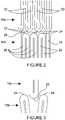
Figure 1 of the accompanying drawings, a portion of aprior art prosthesis 10 is shown. Theprosthesis 10 comprises adistal end 12 and aproximal end 14, with a plurality of stent members orstents 16 spaced apart along the length of theprosthesis 10. Eachstent 16 is spaced apart from the adjacent stent(s) 16 in the longitudinal direction of theprosthesis 10 byconnectors 18. Theconnectors 18 are flexible enough to allow for curvature of theprosthesis 10 during longitudinal compression such as that experienced during deployment. - As can be seen from
Figure 2 , eachstent 16 is formed from a plurality ofstruts 20 with a bend between each pair ofstruts 20. The bends form apexes, and thestents 16 are arranged such that theproximal apexes 22 of onestent 16a are facing thedistal apexes 24 of theadjacent stent 16b.Adjacent stents proximal apexes 22 of onestent 16a are laterally offset from thedistal apexes 24 of theadjacent stent 16b. The apexes are of generally rounded form. - Only two
stents Figure 2 , although this is for clarity purposes only and it will be understood that theprosthesis 10 may in reality comprisemore stents 16 spaced apart along the length of theprosthesis 10. - The
prior art prosthesis 10 shown inFigure 2 is in the compressed configuration. Theprosthesis 10 will be in this configuration during its deployment in a lumen, and will in practice be held in the compressed configuration by means of a sheath (not shown) which forms a part of the introducer assembly. - Once the introducer assembly is in the desired deployment position, the sheath is withdrawn, thus releasing the
prosthesis 10 so that it can expand radially into an expanded condition. The sheath can then be withdrawn completely from the patient. - During deployment of the
prosthesis 10, thecompressed prosthesis 10 will be pushed longitudinally through the patient's vasculature by the introducer assembly. Theprosthesis 10 will be subjected to longitudinal compression forces, and will thus experience longitudinal compression. When theprosthesis 10 is subjected to such longitudinal compression forces, theproximal apexes 22 of thestent 16a move towards thedistal apexes 24 of theadjacent stent 16b such that the space between adjacent stents diminishes. - There are also situations in which the prosthesis may be subjected to longitudinal compression forces other than during deployment. One such situation is when the prosthesis is under development and is being tested by a design engineer in a laboratory. Another situation in which the prosthesis may be subjected to longitudinal compression forces is when the prosthesis is being tested after manufacture, to establish whether or not the manufactured prosthesis is fit for purpose prior to this prosthesis being made available for installation in a patent.
- The
connectors 18 must be flexible enough to allow for curvature of theprosthesis 10 during deployment. As such, the connectors are not stiff enough to prevent engagement ofadjacent stents - Continued longitudinal compression of the
prosthesis 10, to the magnitude of that experienced during deployment (whether this compression results from deployment of the prosthesis or not), causesadjacent stents proximal apexes 22 of onestent 16a will push past thedistal apexes 24 of theadjacent stent 16b such that thestruts 20 lie next to each other in the radial direction and thestents Figure 3 shows, schematically, a portion of theprosthesis 10 in the compressed configuration, under the influence of longitudinal compression forces. Thestents prosthesis 10. It will be understood that this lateral deflection will be magnified if interdigitation occurs throughout theprosthesis 10.- Such lateral deflection of the
prosthesis 10 during deployment thereof is undesirable, as it can cause theprosthesis 10 to press upon the inner surface of the sheath to cause increased friction between the outer surface of the sheath and the lumen wall, thus hindering deployment. This may particularly be the case when theprosthesis 10 is to be deployed in a curved lumen, such as the aortic arch, and in extreme cases lateral deflection can prevent the stent from being located in the desired position. Further, such lateral deflection can be dangerous for the patient in more delicate applications, such as in smaller and more delicate vessels including, for instance, cerebral vessels. - This lateral deflection may be compounded by the action of the
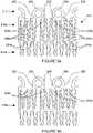
connectors 18 when subjected to longitudinal compression. In this regard, theconnectors 18 deform under longitudinal compression and this deformation could cause at least a portion of theconnectors 18 to press upon the inner surface of the sheath to further increase the friction between the outer surface of the sheath and the lumen wall, thus further hindering deployment. Figure 4 shows a portion of a prosthesis 110 according to an embodiment of the present invention. As with the prior art prosthesis shown inFigures 1 to 3 , the prosthesis 110 comprises adistal end 112 and aproximal end 114, with a plurality ofstents 116 spaced apart along the length of the prosthesis 110.- Each
stent 116 is spaced apart from the adjacent stent(s) 116 in the longitudinal direction of the prosthesis 110 byconnectors 118. Theconnectors 118 are flexible enough to allow for curvature of the prosthesis 110 during deployment. Eachstent 116 is spaced apart from the adjacent stent(s) 116 in the longitudinal direction of the prosthesis 110 by a distance "d". In this embodiment, "d" is 0.1 mm. The longitudinal length of thestents 116 in this embodiment is 2 mm. As such, the distance "d" is 5% of the longitudinal length of thestents 116. - As can be seen from
Figure 5 , eachstent 116 is formed into a generally zig-zag shape, and comprises a plurality ofstruts 120 with an apex 122, 124 between each pair ofstruts 120. Thestruts 120 are substantially straight. Theapexes struts 120 form a more flattened, planar shape. In the present embodiment, the connection between pairs ofstruts 120 is substantially straight. Thestents 116 are arranged such that theproximal apexes 122 of onestent 116a are facing thedistal apexes 124 of theadjacent stent 116b, and the shaped or flat portions of theproximal apexes 122 anddistal apexes 124 are substantially parallel. Further, the shaped or flat portions of theproximal apexes 122 anddistal apexes 124 are substantially perpendicular to the longitudinal direction of the prosthesis 110. - According to the invention,
adjacent stents proximal apexes 122 of onestent 116a are laterally offset from thedistal apexes 124 of theadjacent stent 116b. Figure 5 shows a detailed portion of the prosthesis 110 in the compressed configuration. When in this compressed configuration, eachstrut 120 lies substantially parallel in side-by-side relation to eachother strut 120 of thesame stent 116. The prosthesis 110 is in the compressed configuration during its deployment in a lumen, and is in practice held in the compressed configuration by means of a sheath (not shown) which forms a part of the introducer assembly.- During deployment, the compressed prosthesis 110 is pushed longitudinally through the patient's vasculature by the introducer assembly. The prosthesis 110 is subjected to longitudinal compression forces, and thus experiences longitudinal compression. The flat shape of the proximal 122 and distal 124 apexes provides respective abutment surfaces for
adjacent stents proximal apexes 122 of thestent 116a engage and abut the flat and parallel surfaces of thedistal apexes 124 of theadjacent stent 116b. - There are also situations in which the prosthesis may be subjected to longitudinal compression forces other than during deployment. Examples of such situation are during development of the prosthesis and during testing of the prosthesis after manufacture, as described hereinbefore.
- Engagement of the shaped or flat
proximal apexes 122 of onestent 116a with the shaped or flatdistal apexes 124 of theadjacent stent 116b also acts to prevent excessive deformation of theconnectors 118. - An advantage of the above described arrangement is therefore that the
proximal apexes 122 of onestent 116a are prevented from pushing past thedistal apexes 124 of theadjacent stent 116b. Thus, interdigitation of thestruts 120 is avoided. The avoidance of interdigitation in this way leads in turn to a prevention of lateral deflection of the prosthesis 110 during longitudinal compression, for example during deployment of the prosthesis 110. The integrity of the prosthesis 110 shape is therefore maintained during deployment. - Another advantage of the above described arrangement is that excessive deformation of the
connectors 118 is prevented. Deformation of the connectors could in itself lead to lateral deflection of the prosthesis 110. - A further advantage of the above described arrangement is that the effect of the prosthesis 110 upon the sheath during deployment is substantially reduced or eliminated. As a result, friction between the sheath and the lumen wall, which can be problematic and/or dangerous during deployment of the prosthesis 110, is substantially reduced or eliminated.
- In addition, it is believed that the arrangement described herein will lead to a decrease in the force required to deploy the prosthesis. It is therefore believed that the present invention will find application in drug eluting stents, such as the present applicant's Zilver PTX stents, which are known to cause a significant increase in the force necessary for deployment of the stent. That is to say, the increased force necessary for deployment of a drug eluting stent may be at least partially negated by arranging the stent in accordance with the present invention.
- In a modified arrangement, the stents may be formed from any suitable shape memory alloy. Alternatively, the stents may be formed from a metal such as stainless steel, or a suitable plastics material.
- In a further modified arrangement, the stents may be stitched or otherwise fastened onto a tubular graft material, thus forming a stent graft. In this arrangement, connectors are not required to position the stents longitudinally along the prosthesis.
- Further, although in the preferred embodiment the stents are spaced apart by a distance "d" of 0.1 mm, in modified arrangements the spacing "d" may be at least zero and may be 0.2 mm or less, and is preferably 0.1 mm or less. As such, the stents could be in contact even when the prosthesis is not subjected to longitudinal compression forces.
- In addition, the longitudinal length of the stents is 2 mm in the preferred embodiment, however the stent length may be at least 1 mm, preferably at least 1.4 mm, and may be 3 mm or less, preferably 2.5 mm or less.
- Although the shaped apexes in the preferred embodiment are flat, in modifications the shaped apexes could take on another form. The shaped portion may comprise the whole of, or a part of, the apex. The apexes are shaped such that the apexes of one stent engage or abut the apexes of an adjacent stent, and are thus prevented from pushing past the apexes of the adjacent stent, when the prosthesis is subjected to longitudinal compression forces. Examples of alternative forms of shaped apexes are concave (see
Figure 6 ), castellated (seeFigure 7 ) and undulating (seeFigure 8 ). In these alternate forms, at least a portion of the apex is flat or concave. - According to the invention, the stents are spaced apart from the neighbouring stent(s) by a spacing "d" which is of the order of between zero and 20% of the longitudinal length of the stents. It will be appreciated that a zero spacing corresponds to the apexes being in contact with each other even before longitudinal compression occurs.
Figure 9a shows a portion of aprosthesis 210 according to a second embodiment of the present invention. Theprosthesis 210 comprises adistal end 212 and a proximal end, with a plurality ofstents prosthesis 210. In this embodiment,markers 220 are provided at the proximal and/or distal ends of theprosthesis 210 to assist the physician in positioning the prosthesis during a medical procedure. Thesemarkers 220 are also used as engagement members, so as to provide a contact surface at the end(s) of theprosthesis 210 that may be pushed against, for example when theprosthesis 210 is longitudinally compressed, so that theprosthesis 210 structure itself is not directly pushed against. The markers/engagement members 220 shown inFigure 9a includelateral extensions 222 which extend from the body of theengagement members 220 such that thelateral extensions 222 are located adjacent thedistal apexes 224a of thestent 216a (that is, the apexes which are located at thedistal end 212 of the prosthesis 210). Theselateral extensions 222 are provided so as to increase the potential contact area between theengagement members 220 and theapexes 224a, and to cause theengagement members 220 to engage theapexes 224a, thus preventing theapexes 224a from pushing past thelateral extensions 222 of theengagement members 220.- In addition, the
proximal apexes 226a of thestent 216a and thedistal apexes 224b of thestent 216b have a generally flat or flattened shape, that is to say that, instead of forming a generally rounded bend, the apexes between pairs of struts form a more flattened, planar shape. Thestents proximal apexes 226a of onestent 216a face thedistal apexes 224b of theadjacent stent 216b, and the shaped or flat portions of theproximal apexes 226a anddistal apexes 224b are substantially parallel. Further, the shaped or flat portions of theproximal apexes 226a anddistal apexes 224b are substantially perpendicular to the longitudinal direction of theprosthesis 210. Figure 9b shows a modification of the embodiment shown inFigure 9a . Only those elements which have been modified have been given reference numerals inFigure 9b ; all other elements are similar to those described in connection withFigure 9a . In this modification, theengagement members 320 are modified in that the surfaces of thelateral extensions 322 which face theapexes 324a are planar. Thedistal apexes 324a of thestent 316a are also modified so as to have a generally flat or flattened shape, such that thedistal apexes 324a of thestent 316a are similar to theproximal apexes 226a anddistal apexes 224b shown inFigure 9a . This modification further increases the likelihood of engagement between the planarlateral extensions 322 of theengagement member 320 and the flatteneddistal apexes 324a of thestent 316a when the prosthesis is subjected to longitudinal compression forces, thus preventing thedistal apexes 324a from pushing past thelateral extensions 322.- With prior art arrangements such as that shown in
Figure 1 , longitudinal compression force applied to the prosthesis via the engagement member(s) would be concentrated only on the connector associated with a particular engagement member and the struts adjacent thereto, that is those structural members which are directly connected to an engagement member. Such a concentration of force can lead to bending and deformation of the connector and struts as the prosthesis is longitudinally compressed, for example as it is pushed into a delivery system or released from the delivery system for implantation. - The arrangements shown in
Figures 9a and 9b cause the longitudinal compression force to be distributed to struts which are not directly connected to the engagement member in addition to those connectors and struts which are directly connected to an engagement member. The longitudinal compression force is thus directed to more of the structural members of the prosthesis, and thus laterally across the prosthesis. In addition, due to the flat shape of the stent apexes, longitudinally adjacent stent members are caused to engage upon the application of a longitudinal compression force. Such engagement causes the applied force to be distributed longitudinally throughout the prosthesis as well as being spread out laterally. The combination of a shaped engagement member and shaped apexes can therefore be seen to work synergistically to distribute the compression force both laterally and longitudinally throughout the prosthesis. - Because the longitudinal compression force is spread out more evenly across the prosthesis, bending and deformation of the connectors and struts of the prosthesis is minimised. This is especially advantageous when prostheses of longer length are used, since such prostheses typically require the application of greater pushing forces due to increased friction.
Claims (15)
- A substantially tubular prosthesis (110; 210) comprising a plurality of stent members (116, 116a, 116b; 216a, 216b; 316a) positioned longitudinally along the prosthesis, each stent member comprising a plurality of strut elements (120) connected by apexes (122, 124; 224a, 224b, 226a; 324a), the prosthesis being arranged such that proximal apexes (122; 226a) of a first stent member (116a; 216a) engage distal apexes (124; 224b) of a longitudinally adjacent second stent member (116b; 216b) when the prosthesis is subjected to longitudinal compression forces, each of the proximal apexes of the first stent member and the distal apexes of the second stent member having a shaped portion which is flat or concave and having a width, so as to present a line of engagement surfaces to the distal apexes of the second stent member and the proximal apexes of the first stent member respectively, wherein gaps between circumferentially adjacent engagement surfaces are narrower than the widths of the shaped portions when the prosthesis is in a compressed configuration;wherein each of the plurality of stent members is spaced apart from an adjacent stent member by a spacing (d) of the order of between zero and 20% of a longitudinal length of the stent members in a compressed configuration of the prosthesis;wherein the adjacent stent members are in a staggered arrangement in which proximal apexes of one stent member are laterally offset from distal apexes of the adjacent stent member.
- A prosthesis according to claim 1, wherein the shaped portions are substantially planar.
- A prosthesis according to claim 2, wherein the shaped portions are substantially perpendicular to the longitudinal direction of the prosthesis (110; 210).
- A prosthesis according to claim 2 or 3, wherein the proximal apexes (122; 226a) of the first stent member (116a; 216a) are substantially parallel to the distal apexes (124; 224b) of the second stent member (116b; 216b).
- A prosthesis according to any preceding claim, wherein the strut elements (120) are substantially parallel when the prosthesis is in a compressed configuration.
- A prosthesis according to any preceding claim, wherein each stent member (116, 116a, 116b; 216a, 216b; 316a) is spaced apart from an adjacent stent member by at least one connector (118).
- A prosthesis according to claim 6, further comprising at least one engagement member (220; 320) located at an end of the prosthesis, the engagement member comprising a lateral extension (222; 322) which extends adjacent the distal apexes (224a; 324a) of the first stent member (216a; 316a) such that the lateral extension engages the distal apexes of the first stent member when the prosthesis is subjected to longitudinal compression forces, the lateral extension being shaped to form a substantially planar engagement surface facing the distal apexes of the first stent member.
- A prosthesis according to any preceding claim, wherein the stent members (116, 116a, 116b; 216a, 216b; 316a) are fastened to a graft material to form a stent graft.
- A prosthesis according to claim 8, wherein the stent members (116, 116a, 116b; 216a, 216b; 316a) are fastened to the graft such that each stent member is spaced apart from an adjacent stent member.
- A method of manufacturing a substantially tubular prosthesis (110; 210), the method comprising the steps of:forming a plurality of stent members (116, 116a, 116b; 216a, 216b; 316a) positioned longitudinally along the prosthesis, wherein each stent member comprises a plurality of strut elements (120) connected by apexes (122, 124; 224a;, 224b, 226a; 324a);arranging the prosthesis such that proximal apexes (122; 226a) of a first stent member (116a; 216a) engage distal apexes (124; 224b) of a longitudinally adjacent second stent member (116b; 216b) when the prosthesis is subjected to longitudinal compression forces; andforming each of the proximal apexes of the first stent member and the distal apexes of the second stent member to have a shaped portion which is flat or concave and to have a width, so as to present a line of engagement surfaces to the distal apexes of the second stent member and the proximal apexes of the first stent member respectively, wherein gaps between circumferentially adjacent engagement surfaces are narrower than the widths of the shaped portions when the prosthesis is in a compressed configuration;wherein each of the plurality of stent members is spaced apart from an adjacent stent member by a spacing (d) of the order of between zero and 20% of a longitudinal length of the stent members in a compressed configuration of the prosthesis;wherein the adjacent stent members are in a staggered arrangement in which proximal apexes of one stent member are laterally offset from distal apexes of the adjacent stent member.
- A method according to claim 10, wherein the shaped portions are formed to be substantially planar.
- A method according to claim 11, wherein the shaped portions are formed to be substantially perpendicular to the longitudinal direction of the prosthesis (110; 210).
- A method according to claim 11 or 12, wherein the proximal apexes (122; 226a) of the first stent member (116a; 216a) are formed to be substantially parallel to the distal apexes (124; 224b) of the second stent member (116b; 216b).
- A method according to any one of claims 10 to 13, wherein the stent members (116, 116a, 116b; 216a, 216b; 316a) are formed such that the strut elements (120) are substantially parallel when the prosthesis (110; 210) is in a compressed configuration.
- A method according to any one of claims 10 to 14, wherein the prosthesis (110; 210) is formed such that each stent member (116, 116a, 116b; 216a, 216b; 316a) is spaced apart from an adjacent stent member by at least one connector (118).
Applications Claiming Priority (1)
| Application Number | Priority Date | Filing Date | Title |
|---|---|---|---|
| GB1102859.4AGB2488165B (en) | 2011-02-18 | 2011-02-18 | Prosthesis and method of manufacturing the same |
Publications (2)
| Publication Number | Publication Date |
|---|---|
| EP2489337A1 EP2489337A1 (en) | 2012-08-22 |
| EP2489337B1true EP2489337B1 (en) | 2022-07-06 |
Family
ID=43881325
Family Applications (1)
| Application Number | Title | Priority Date | Filing Date |
|---|---|---|---|
| EP12275017.7AActiveEP2489337B1 (en) | 2011-02-18 | 2012-02-17 | Prosthesis and method of manufacture |
Country Status (4)
| Country | Link |
|---|---|
| US (1) | US20120215298A1 (en) |
| EP (1) | EP2489337B1 (en) |
| AU (1) | AU2012200935B2 (en) |
| GB (1) | GB2488165B (en) |
Families Citing this family (2)
| Publication number | Priority date | Publication date | Assignee | Title |
|---|---|---|---|---|
| US12263104B2 (en)* | 2021-05-20 | 2025-04-01 | Cook Medical Technologies Llc | Self expanding stents and methods |
| WO2022245435A1 (en)* | 2021-05-20 | 2022-11-24 | Cook Medical Technologies Llc | Self expanding stent and method of loading same into a catheter |
Citations (2)
| Publication number | Priority date | Publication date | Assignee | Title |
|---|---|---|---|---|
| US5755776A (en)* | 1996-10-04 | 1998-05-26 | Al-Saadon; Khalid | Permanent expandable intraluminal tubular stent |
| WO1998028035A1 (en)* | 1996-12-24 | 1998-07-02 | Global Therapeutics, Inc. | Radially expandable axially non-contracting surgical stent |
Family Cites Families (17)
| Publication number | Priority date | Publication date | Assignee | Title |
|---|---|---|---|---|
| US3366912A (en) | 1965-08-25 | 1968-01-30 | Du Pont | Electrical heating element |
| IL123039A (en) | 1995-07-25 | 2002-02-10 | Medstent Inc | Expandible stent |
| WO1998020810A1 (en) | 1996-11-12 | 1998-05-22 | Medtronic, Inc. | Flexible, radially expansible luminal prostheses |
| US6309414B1 (en)* | 1997-11-04 | 2001-10-30 | Sorin Biomedica Cardio S.P.A. | Angioplasty stents |
| EP1065993B1 (en)* | 1998-03-05 | 2010-08-11 | Boston Scientific Limited | Intraluminal stent |
| US6551351B2 (en)* | 1999-07-02 | 2003-04-22 | Scimed Life Systems | Spiral wound stent |
| US6939373B2 (en) | 2003-08-20 | 2005-09-06 | Advanced Cardiovascular Systems, Inc. | Intravascular stent |
| WO2003030786A2 (en)* | 2001-10-09 | 2003-04-17 | William Cook Europe Aps | Cannula stent |
| AU2003239369A1 (en) | 2002-05-06 | 2003-11-17 | Abbott Laboratories | Endoprosthesis for controlled contraction and expansion |
| US6656220B1 (en)* | 2002-06-17 | 2003-12-02 | Advanced Cardiovascular Systems, Inc. | Intravascular stent |
| US20050149168A1 (en) | 2003-12-30 | 2005-07-07 | Daniel Gregorich | Stent to be deployed on a bend |
| US8435280B2 (en)* | 2005-03-31 | 2013-05-07 | Boston Scientific Scimed, Inc. | Flexible stent with variable width elements |
| US7381217B2 (en)* | 2005-12-23 | 2008-06-03 | Boston Scientific Scimed, Inc. | Serpentine stent pattern |
| US8066760B2 (en) | 2006-04-18 | 2011-11-29 | Medtronic Vascular, Inc. | Stent with movable crown |
| GB0609911D0 (en) | 2006-05-18 | 2006-06-28 | Angiomed Ag | Bend-capable stent prosthesis |
| US8133268B2 (en)* | 2007-05-30 | 2012-03-13 | Cordis Corporation | Stent/fiber structural combinations |
| US20090210049A1 (en)* | 2008-02-15 | 2009-08-20 | Joseph Michael Thielen | Peripheral overlap stent |
- 2011
- 2011-02-18GBGB1102859.4Apatent/GB2488165B/enactiveActive
- 2012
- 2012-02-09USUS13/369,922patent/US20120215298A1/ennot_activeAbandoned
- 2012-02-17EPEP12275017.7Apatent/EP2489337B1/enactiveActive
- 2012-02-17AUAU2012200935Apatent/AU2012200935B2/enactiveActive
Patent Citations (2)
| Publication number | Priority date | Publication date | Assignee | Title |
|---|---|---|---|---|
| US5755776A (en)* | 1996-10-04 | 1998-05-26 | Al-Saadon; Khalid | Permanent expandable intraluminal tubular stent |
| WO1998028035A1 (en)* | 1996-12-24 | 1998-07-02 | Global Therapeutics, Inc. | Radially expandable axially non-contracting surgical stent |
Also Published As
| Publication number | Publication date |
|---|---|
| GB2488165A (en) | 2012-08-22 |
| EP2489337A1 (en) | 2012-08-22 |
| US20120215298A1 (en) | 2012-08-23 |
| GB2488165B (en) | 2013-08-07 |
| AU2012200935B2 (en) | 2013-08-22 |
| GB201102859D0 (en) | 2011-04-06 |
| AU2012200935A1 (en) | 2012-09-06 |
Similar Documents
| Publication | Publication Date | Title |
|---|---|---|
| EP2403441B1 (en) | Stent | |
| US6270524B1 (en) | Flexible, radially expansible luminal prostheses | |
| US8016874B2 (en) | Flexible stent with elevated scaffolding properties | |
| EP1895952B1 (en) | Intraluminal device with unsymmetric tapered beams | |
| EP2816971B1 (en) | Stent having at least one connecting member configured to controllably sever in vivo | |
| EP2961358B1 (en) | Implantable medical devices for reduced tissue inflammation | |
| EP3654878B1 (en) | Intravascular stent | |
| KR102197010B1 (en) | Stent | |
| JP2008522757A (en) | Variable curvature stent | |
| KR102195532B1 (en) | Stent | |
| EP3632376B1 (en) | Self-curving stent graft | |
| WO2011028754A1 (en) | Vascular prosthesis with stress relief slots | |
| EP3431052B1 (en) | Stent with segments capable of uncoupling during expansion | |
| EP1895934B1 (en) | Intraluminal device with improved tapered beams | |
| EP3417833A1 (en) | Intraluminal support device with end cell geometry | |
| EP2489337B1 (en) | Prosthesis and method of manufacture | |
| EP3010451B1 (en) | Stent with deflecting connector | |
| US20090093869A1 (en) | Medical device with curved struts | |
| EP2745806A2 (en) | Stent designs for reduced infolding of graft material | |
| WO2009118912A1 (en) | Stent and stent graft |
Legal Events
| Date | Code | Title | Description |
|---|---|---|---|
| PUAI | Public reference made under article 153(3) epc to a published international application that has entered the european phase | Free format text:ORIGINAL CODE: 0009012 | |
| AK | Designated contracting states | Kind code of ref document:A1 Designated state(s):AL AT BE BG CH CY CZ DE DK EE ES FI FR GB GR HR HU IE IS IT LI LT LU LV MC MK MT NL NO PL PT RO RS SE SI SK SM TR | |
| AX | Request for extension of the european patent | Extension state:BA ME | |
| 17P | Request for examination filed | Effective date:20120921 | |
| STAA | Information on the status of an ep patent application or granted ep patent | Free format text:STATUS: EXAMINATION IS IN PROGRESS | |
| 17Q | First examination report despatched | Effective date:20170206 | |
| REG | Reference to a national code | Ref country code:DE Ref legal event code:R079 Ref document number:602012078441 Country of ref document:DE Free format text:PREVIOUS MAIN CLASS: A61F0002900000 Ipc:A61F0002915000 | |
| RIC1 | Information provided on ipc code assigned before grant | Ipc:A61F 2/915 20130101AFI20210504BHEP | |
| GRAP | Despatch of communication of intention to grant a patent | Free format text:ORIGINAL CODE: EPIDOSNIGR1 | |
| STAA | Information on the status of an ep patent application or granted ep patent | Free format text:STATUS: GRANT OF PATENT IS INTENDED | |
| INTG | Intention to grant announced | Effective date:20220120 | |
| GRAS | Grant fee paid | Free format text:ORIGINAL CODE: EPIDOSNIGR3 | |
| GRAA | (expected) grant | Free format text:ORIGINAL CODE: 0009210 | |
| STAA | Information on the status of an ep patent application or granted ep patent | Free format text:STATUS: THE PATENT HAS BEEN GRANTED | |
| AK | Designated contracting states | Kind code of ref document:B1 Designated state(s):AL AT BE BG CH CY CZ DE DK EE ES FI FR GR HR HU IE IS IT LI LT LU LV MC MK MT NL NO PL PT RO RS SE SI SK SM TR | |
| RBV | Designated contracting states (corrected) | Designated state(s):AL AT BE BG CH CY CZ DE DK EE ES FI FR GR HR HU IE IS IT LI LT LU LV MC MK MT NL NO PL PT RO RS SE SI SK SM TR | |
| REG | Reference to a national code | Ref country code:AT Ref legal event code:REF Ref document number:1502334 Country of ref document:AT Kind code of ref document:T Effective date:20220715 Ref country code:CH Ref legal event code:EP | |
| REG | Reference to a national code | Ref country code:DE Ref legal event code:R096 Ref document number:602012078441 Country of ref document:DE | |
| REG | Reference to a national code | Ref country code:IE Ref legal event code:FG4D | |
| REG | Reference to a national code | Ref country code:LT Ref legal event code:MG9D | |
| REG | Reference to a national code | Ref country code:NL Ref legal event code:MP Effective date:20220706 | |
| PG25 | Lapsed in a contracting state [announced via postgrant information from national office to epo] | Ref country code:SE Free format text:LAPSE BECAUSE OF FAILURE TO SUBMIT A TRANSLATION OF THE DESCRIPTION OR TO PAY THE FEE WITHIN THE PRESCRIBED TIME-LIMIT Effective date:20220706 Ref country code:RS Free format text:LAPSE BECAUSE OF FAILURE TO SUBMIT A TRANSLATION OF THE DESCRIPTION OR TO PAY THE FEE WITHIN THE PRESCRIBED TIME-LIMIT Effective date:20220706 Ref country code:PT Free format text:LAPSE BECAUSE OF FAILURE TO SUBMIT A TRANSLATION OF THE DESCRIPTION OR TO PAY THE FEE WITHIN THE PRESCRIBED TIME-LIMIT Effective date:20221107 Ref country code:NO Free format text:LAPSE BECAUSE OF FAILURE TO SUBMIT A TRANSLATION OF THE DESCRIPTION OR TO PAY THE FEE WITHIN THE PRESCRIBED TIME-LIMIT Effective date:20221006 Ref country code:NL Free format text:LAPSE BECAUSE OF FAILURE TO SUBMIT A TRANSLATION OF THE DESCRIPTION OR TO PAY THE FEE WITHIN THE PRESCRIBED TIME-LIMIT Effective date:20220706 Ref country code:LV Free format text:LAPSE BECAUSE OF FAILURE TO SUBMIT A TRANSLATION OF THE DESCRIPTION OR TO PAY THE FEE WITHIN THE PRESCRIBED TIME-LIMIT Effective date:20220706 Ref country code:LT Free format text:LAPSE BECAUSE OF FAILURE TO SUBMIT A TRANSLATION OF THE DESCRIPTION OR TO PAY THE FEE WITHIN THE PRESCRIBED TIME-LIMIT Effective date:20220706 Ref country code:FI Free format text:LAPSE BECAUSE OF FAILURE TO SUBMIT A TRANSLATION OF THE DESCRIPTION OR TO PAY THE FEE WITHIN THE PRESCRIBED TIME-LIMIT Effective date:20220706 Ref country code:ES Free format text:LAPSE BECAUSE OF FAILURE TO SUBMIT A TRANSLATION OF THE DESCRIPTION OR TO PAY THE FEE WITHIN THE PRESCRIBED TIME-LIMIT Effective date:20220706 | |
| REG | Reference to a national code | Ref country code:AT Ref legal event code:MK05 Ref document number:1502334 Country of ref document:AT Kind code of ref document:T Effective date:20220706 | |
| PG25 | Lapsed in a contracting state [announced via postgrant information from national office to epo] | Ref country code:PL Free format text:LAPSE BECAUSE OF FAILURE TO SUBMIT A TRANSLATION OF THE DESCRIPTION OR TO PAY THE FEE WITHIN THE PRESCRIBED TIME-LIMIT Effective date:20220706 Ref country code:IS Free format text:LAPSE BECAUSE OF FAILURE TO SUBMIT A TRANSLATION OF THE DESCRIPTION OR TO PAY THE FEE WITHIN THE PRESCRIBED TIME-LIMIT Effective date:20221106 Ref country code:HR Free format text:LAPSE BECAUSE OF FAILURE TO SUBMIT A TRANSLATION OF THE DESCRIPTION OR TO PAY THE FEE WITHIN THE PRESCRIBED TIME-LIMIT Effective date:20220706 Ref country code:GR Free format text:LAPSE BECAUSE OF FAILURE TO SUBMIT A TRANSLATION OF THE DESCRIPTION OR TO PAY THE FEE WITHIN THE PRESCRIBED TIME-LIMIT Effective date:20221007 | |
| REG | Reference to a national code | Ref country code:DE Ref legal event code:R097 Ref document number:602012078441 Country of ref document:DE | |
| PG25 | Lapsed in a contracting state [announced via postgrant information from national office to epo] | Ref country code:SM Free format text:LAPSE BECAUSE OF FAILURE TO SUBMIT A TRANSLATION OF THE DESCRIPTION OR TO PAY THE FEE WITHIN THE PRESCRIBED TIME-LIMIT Effective date:20220706 Ref country code:RO Free format text:LAPSE BECAUSE OF FAILURE TO SUBMIT A TRANSLATION OF THE DESCRIPTION OR TO PAY THE FEE WITHIN THE PRESCRIBED TIME-LIMIT Effective date:20220706 Ref country code:DK Free format text:LAPSE BECAUSE OF FAILURE TO SUBMIT A TRANSLATION OF THE DESCRIPTION OR TO PAY THE FEE WITHIN THE PRESCRIBED TIME-LIMIT Effective date:20220706 Ref country code:CZ Free format text:LAPSE BECAUSE OF FAILURE TO SUBMIT A TRANSLATION OF THE DESCRIPTION OR TO PAY THE FEE WITHIN THE PRESCRIBED TIME-LIMIT Effective date:20220706 Ref country code:AT Free format text:LAPSE BECAUSE OF FAILURE TO SUBMIT A TRANSLATION OF THE DESCRIPTION OR TO PAY THE FEE WITHIN THE PRESCRIBED TIME-LIMIT Effective date:20220706 | |
| PLBE | No opposition filed within time limit | Free format text:ORIGINAL CODE: 0009261 | |
| STAA | Information on the status of an ep patent application or granted ep patent | Free format text:STATUS: NO OPPOSITION FILED WITHIN TIME LIMIT | |
| PG25 | Lapsed in a contracting state [announced via postgrant information from national office to epo] | Ref country code:SK Free format text:LAPSE BECAUSE OF FAILURE TO SUBMIT A TRANSLATION OF THE DESCRIPTION OR TO PAY THE FEE WITHIN THE PRESCRIBED TIME-LIMIT Effective date:20220706 Ref country code:EE Free format text:LAPSE BECAUSE OF FAILURE TO SUBMIT A TRANSLATION OF THE DESCRIPTION OR TO PAY THE FEE WITHIN THE PRESCRIBED TIME-LIMIT Effective date:20220706 | |
| 26N | No opposition filed | Effective date:20230411 | |
| PG25 | Lapsed in a contracting state [announced via postgrant information from national office to epo] | Ref country code:AL Free format text:LAPSE BECAUSE OF FAILURE TO SUBMIT A TRANSLATION OF THE DESCRIPTION OR TO PAY THE FEE WITHIN THE PRESCRIBED TIME-LIMIT Effective date:20220706 | |
| P01 | Opt-out of the competence of the unified patent court (upc) registered | Effective date:20230602 | |
| PG25 | Lapsed in a contracting state [announced via postgrant information from national office to epo] | Ref country code:SI Free format text:LAPSE BECAUSE OF FAILURE TO SUBMIT A TRANSLATION OF THE DESCRIPTION OR TO PAY THE FEE WITHIN THE PRESCRIBED TIME-LIMIT Effective date:20220706 | |
| PG25 | Lapsed in a contracting state [announced via postgrant information from national office to epo] | Ref country code:MC Free format text:LAPSE BECAUSE OF FAILURE TO SUBMIT A TRANSLATION OF THE DESCRIPTION OR TO PAY THE FEE WITHIN THE PRESCRIBED TIME-LIMIT Effective date:20220706 | |
| REG | Reference to a national code | Ref country code:CH Ref legal event code:PL | |
| REG | Reference to a national code | Ref country code:BE Ref legal event code:MM Effective date:20230228 | |
| PG25 | Lapsed in a contracting state [announced via postgrant information from national office to epo] | Ref country code:LU Free format text:LAPSE BECAUSE OF NON-PAYMENT OF DUE FEES Effective date:20230217 Ref country code:LI Free format text:LAPSE BECAUSE OF NON-PAYMENT OF DUE FEES Effective date:20230228 Ref country code:CH Free format text:LAPSE BECAUSE OF NON-PAYMENT OF DUE FEES Effective date:20230228 | |
| PG25 | Lapsed in a contracting state [announced via postgrant information from national office to epo] | Ref country code:IT Free format text:LAPSE BECAUSE OF FAILURE TO SUBMIT A TRANSLATION OF THE DESCRIPTION OR TO PAY THE FEE WITHIN THE PRESCRIBED TIME-LIMIT Effective date:20220706 Ref country code:FR Free format text:LAPSE BECAUSE OF NON-PAYMENT OF DUE FEES Effective date:20230228 | |
| PG25 | Lapsed in a contracting state [announced via postgrant information from national office to epo] | Ref country code:BE Free format text:LAPSE BECAUSE OF NON-PAYMENT OF DUE FEES Effective date:20230228 | |
| PG25 | Lapsed in a contracting state [announced via postgrant information from national office to epo] | Ref country code:BG Free format text:LAPSE BECAUSE OF FAILURE TO SUBMIT A TRANSLATION OF THE DESCRIPTION OR TO PAY THE FEE WITHIN THE PRESCRIBED TIME-LIMIT Effective date:20220706 | |
| PG25 | Lapsed in a contracting state [announced via postgrant information from national office to epo] | Ref country code:BG Free format text:LAPSE BECAUSE OF FAILURE TO SUBMIT A TRANSLATION OF THE DESCRIPTION OR TO PAY THE FEE WITHIN THE PRESCRIBED TIME-LIMIT Effective date:20220706 | |
| PGFP | Annual fee paid to national office [announced via postgrant information from national office to epo] | Ref country code:DE Payment date:20250226 Year of fee payment:14 | |
| PGFP | Annual fee paid to national office [announced via postgrant information from national office to epo] | Ref country code:IE Payment date:20250217 Year of fee payment:14 | |
| PG25 | Lapsed in a contracting state [announced via postgrant information from national office to epo] | Ref country code:CY Free format text:LAPSE BECAUSE OF FAILURE TO SUBMIT A TRANSLATION OF THE DESCRIPTION OR TO PAY THE FEE WITHIN THE PRESCRIBED TIME-LIMIT; INVALID AB INITIO Effective date:20120217 | |
| PG25 | Lapsed in a contracting state [announced via postgrant information from national office to epo] | Ref country code:HU Free format text:LAPSE BECAUSE OF FAILURE TO SUBMIT A TRANSLATION OF THE DESCRIPTION OR TO PAY THE FEE WITHIN THE PRESCRIBED TIME-LIMIT; INVALID AB INITIO Effective date:20120217 |