EP2486226B1 - Interchangeable drillable tool - Google Patents
Interchangeable drillable toolDownload PDFInfo
- Publication number
- EP2486226B1 EP2486226B1EP10763841.3AEP10763841AEP2486226B1EP 2486226 B1EP2486226 B1EP 2486226B1EP 10763841 AEP10763841 AEP 10763841AEP 2486226 B1EP2486226 B1EP 2486226B1
- Authority
- EP
- European Patent Office
- Prior art keywords
- mandrel
- slip
- tool
- downhole tool
- disposed
- Prior art date
- Legal status (The legal status is an assumption and is not a legal conclusion. Google has not performed a legal analysis and makes no representation as to the accuracy of the status listed.)
- Not-in-force
Links
- 238000007789sealingMethods0.000claimsdescription34
- 238000001125extrusionMethods0.000claimsdescription26
- 239000012530fluidSubstances0.000claimsdescription25
- 239000002131composite materialSubstances0.000claimsdescription21
- 239000011152fibreglassSubstances0.000claimsdescription15
- 125000006850spacer groupChemical group0.000claimsdescription9
- 229920001971elastomerPolymers0.000claimsdescription8
- 239000000463materialSubstances0.000claimsdescription8
- 239000003822epoxy resinSubstances0.000claimsdescription4
- 229920000647polyepoxidePolymers0.000claimsdescription4
- 230000007704transitionEffects0.000claimsdescription4
- 230000004888barrier functionEffects0.000claimsdescription2
- 239000007787solidSubstances0.000claims1
- ORQBXQOJMQIAOY-UHFFFAOYSA-NnobeliumChemical compound[No]ORQBXQOJMQIAOY-UHFFFAOYSA-N0.000description8
- 230000015572biosynthetic processEffects0.000description7
- 238000005755formation reactionMethods0.000description7
- 239000004593EpoxySubstances0.000description6
- 239000002002slurrySubstances0.000description6
- 239000000853adhesiveSubstances0.000description5
- 230000001070adhesive effectEffects0.000description5
- 241001331845Equus asinus x caballusSpecies0.000description4
- 229920000459Nitrile rubberPolymers0.000description4
- -1for exampleSubstances0.000description4
- 238000002955isolationMethods0.000description3
- 244000309464bullSpecies0.000description2
- 238000010276constructionMethods0.000description2
- 239000000835fiberSubstances0.000description2
- OKTJSMMVPCPJKN-UHFFFAOYSA-NCarbonChemical compound[C]OKTJSMMVPCPJKN-UHFFFAOYSA-N0.000description1
- 229910001018Cast ironInorganic materials0.000description1
- 229910000831SteelInorganic materials0.000description1
- 239000004760aramidSubstances0.000description1
- 229920003235aromatic polyamidePolymers0.000description1
- 230000000712assemblyEffects0.000description1
- 238000000429assemblyMethods0.000description1
- 229910052799carbonInorganic materials0.000description1
- 239000004568cementSubstances0.000description1
- 239000000919ceramicSubstances0.000description1
- 238000004891communicationMethods0.000description1
- 230000003247decreasing effectEffects0.000description1
- 230000001934delayEffects0.000description1
- 230000001419dependent effectEffects0.000description1
- 238000005553drillingMethods0.000description1
- 239000004744fabricSubstances0.000description1
- 239000011521glassSubstances0.000description1
- 230000013011matingEffects0.000description1
- 239000007769metal materialSubstances0.000description1
- 238000000034methodMethods0.000description1
- 239000003129oil wellSubstances0.000description1
- ISWSIDIOOBJBQZ-UHFFFAOYSA-Nphenol groupChemical groupC1(=CC=CC=C1)OISWSIDIOOBJBQZ-UHFFFAOYSA-N0.000description1
- 239000004033plasticSubstances0.000description1
- 229920003023plasticPolymers0.000description1
- 229920005989resinPolymers0.000description1
- 239000011347resinSubstances0.000description1
- 239000010959steelSubstances0.000description1
- 238000004804windingMethods0.000description1
Images


Classifications
- E—FIXED CONSTRUCTIONS
- E21—EARTH OR ROCK DRILLING; MINING
- E21B—EARTH OR ROCK DRILLING; OBTAINING OIL, GAS, WATER, SOLUBLE OR MELTABLE MATERIALS OR A SLURRY OF MINERALS FROM WELLS
- E21B33/00—Sealing or packing boreholes or wells
- E21B33/10—Sealing or packing boreholes or wells in the borehole
- E21B33/12—Packers; Plugs
- E21B33/1208—Packers; Plugs characterised by the construction of the sealing or packing means
- E—FIXED CONSTRUCTIONS
- E21—EARTH OR ROCK DRILLING; MINING
- E21B—EARTH OR ROCK DRILLING; OBTAINING OIL, GAS, WATER, SOLUBLE OR MELTABLE MATERIALS OR A SLURRY OF MINERALS FROM WELLS
- E21B33/00—Sealing or packing boreholes or wells
- E21B33/10—Sealing or packing boreholes or wells in the borehole
- E21B33/12—Packers; Plugs
- E21B33/127—Packers; Plugs with inflatable sleeve
- E21B33/1277—Packers; Plugs with inflatable sleeve characterised by the construction or fixation of the sleeve
Definitions
- This disclosuregenerally relates to tools used in oil and gas wellbores. More specifically, the disclosure relates to drillable packers and pressure isolation tools.
- downhole toolsIn the drilling or reworking of oil wells, a great variety of downhole tools are used. Such downhole tools often have drillable components made from metallic or non-metallic materials such as soft steel, cast iron or engineering glade plastics and composite materials. For example, but not by way of limitation, it is often desirable to seal tubing or other pipe in the well when it is desired to pump a slurry down the tubing and force the slurry out into the formation.
- the slurrymay include for example fracturing fluid. It is necessary to seal the tubing with respect to the well casing and to prevent the fluid pressure of the slurry from lifting the tubing out of the well and likewise to force the slurry into the formation if that is the desired result.
- Downhole tools referred to as packers, frac plugs and bridge plugsare designed for these general purposes and are well known in the art of producing oil and gas.
- Bridge plugsisolate the portion of the well below the bridge plug from the portion of the well thereabove. Thus, there is no communication from the portions above and below the bridge plug.
- Frac plugsallow fluid flow in one direction but prevent flow in the other.
- frac plugs set in a wellmay allow fluid from below the frac plug to pass upwardly therethrough but when the slurry is pumped into the well, the frac plug will not allow flow therethrough so that any fluid being pumped down the well may be forced into a formation above the frac plug.
- the toolis assembled as a frac plug or bridge plug.
- An easily disassemblable toolthat can be configured as a frac plug or a bridge plug provides advantages over prior art tools. While there are some tools that are convertible, there is a continuing need for tools that may be converted between frac plugs and bridge plugs more easily and efficiently. In addition, tools that allow for high run-in speeds are desired.
- US 2004/0045723discloses methods and apparatus for a drillable bridge plug, frac plug, cement retainer, and other related downhole apparatus, including apparatus for running these downhole apparatus.
- WO 2004/070163discloses inflatable packer assemblies and bridge plugs that incorporate selective components made of a composite material.
- a downhole tool for use in a wellhas a mandrel with an expandable sealing element having first and second ends disposed thereabout.
- the mandrelis a composite comprised of a plurality of wound layers of fiberglass filaments coated in epoxy.
- the downhole toolis movable from an unset position to a set position in the well in which the sealing element engages the well, and preferably engages a casing in the well.
- the sealing elementis likewise movable from an unset to a set position.
- First and second extrusion limitersare positioned at the first and second ends of the sealing element.
- the first and second extrusion limitersmay be comprised of a plurality of composite layers with rubber layers therebetween.
- the extrusion limitersmay comprise a plurality of layers of fiberglass, for example, fiberglass filaments or fibers covered with epoxy resin, with layers of rubber, for example, nitrile rubber adjacent thereto.
- the first and second extrusion limitersmay have an arcuately shaped cross section and be molded to the sealing element.
- First and second slip wedgesare likewise disposed about the mandrel.
- Each of the first and second slip wedgeshave an abutment end which abuts the first and second extrusion limiters, respectively.
- the abutment end of the first and second slip wedgespreferably comprise a flat portion that extends radially outwardly from a mandrel outer surface and has a rounded transition from the flat portion to a radially outer surface of the slip wedge.
- First and second slip ringsare disposed about the mandrel and will ride on the slip wedges so that the first and second slip wedges will expand the first and second slip rings radially outwardly to grippingly engage casing in the well in response to relative axial movement.
- the first and second slip ringseach comprise a plurality of individual slip segments that are bonded to one another at side surfaces thereof. Each of the slip segments have end surfaces and at least one of the end surfaces has a groove therein.
- the grooves in the slip segmentstogether define a retaining groove in the first and second slip rings.
- a retaining bandis disposed in the retaining grooves in the first and second slip rings and is not exposed to fluid in the well.
- the downhole toolhas a head portion that is threaded to the mandrel.
- the head portionmay be comprised of a composite material and the threaded connection is designed to withstand load experienced in the well.
- the threadallows the downhole tool to be easily disassembled so that the tool may be easily converted or interchanged between a frac plug and bridge plug.
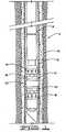
- FIG. 1a downhole tool 10 is shown in a well 15 which comprises wellbore 20 with casing 25 cemented therein.
- Tool 10may be lowered into well 15 on a tubing 30 or may be lowered on a wireline or other means known in the art.
- FIG. 1shows tool 10 in its set position in the well.
- Downhole tool 10comprises a mandrel 32 with an outer surface 34 and inner surface 36.
- Mandrel 32may be a composite mandrel constructed of a polymeric composite with continuous fibers such as glass, carbon or aramid, for example.
- Mandrel 32may, for example, be a composite mandrel comprising layers of wound fiberglass filaments held together with an epoxy resin, and may be constructed by winding layers of fiberglass filaments around a forming mandrel. A plurality of fiberglass filaments may be pulled through an epoxy bath so that the filaments are coated with epoxy prior to being wound around the forming mandrel. Any number of filaments may be wound, and for example eight strands may be wound around the mandrel at a time.
- Composite mandrel 32comprises a plurality of the layers.
- Composite mandrel 32has bore 40 defined by inner surface 36.
- Mandrel 32has upper or top end 42 and lower or bottom end 44. Bore 40 defines a central flow passage 46 therethrough.
- An end section 48may comprise a mule shoe 48.
- the end section or mule shoeis generally a separate piece that is connected with pins to a tubular mandrel.
- Mandrel 32includes mule shoe 48 that is integrally formed therewith and thus is laid up and formed in the manner described herein.
- Mule shoe 48defines an upward facing shoulder 50 thereon.
- Mandrel 32has a first or upper outer diameter 52, a second or first intermediate outer diameter 54 which is a threaded outer diameter 54, a third or second intermediate inner diameter 56 and a fourth or lower outer diameter 58. Shoulder 50 is defined by and extends between third and fourth outer diameters 56 and 58, respectively. Threads 60 defined on threaded diameter 54 may comprise a high strength composite buttress thread. A head or head portion 62 is threadedly connected to mandrel 32 and thus has mating buttress threads 64 thereon.
- Head portion 62has an upper end 66 that may comprise a plug or ball seat 68. Head 62 has lower end 70 and has first, second and third inner diameters 72, 74, 76, respectively. Buttress threads 64 are defined on third inner diameter 76. Second inner diameter 74 has a magnitude greater than first inner diameter 72 and third inner diameter 76 has a magnitude greater than second inner diameter 74. A shoulder 78 is defined by and extends between first and second inner diameters 72 and 74. Shoulder 78 and upper end 42 of mandrel 32 define an annular space 80 therebetween. In the embodiment of FIG. 2 , a spacer sleeve 82 is disposed in annular space 80.
- Spacer sleeve 82has an open bore 84 so that fluid may pass unobstructed therethrough into and through longitudinal central passageway 46.
- head portion 62is easily disconnected by unthreading from mandrel 32 so that instead of spacer sleeve 82 a plug 86, which is shown in FIG. 4 may be utilized. Plug 86 will prevent flow in either direction and as such the tool depicted in FIG. 4 will act as a bridge plug.
- a spacer ring 90is disposed about mandrel 32 and abuts lower end 70 of head portion 62 so that it is axially restrained on mandrel 32.
- Tool 10further comprises a pair of slip rings 92, first and second, or upper and lower slip rings 94 and 96, respectively, with first and second ends 95 and 97 disposed about mandrel 32.
- a pair of slip wedges 99which may comprise first and second or upper and lower slip wedges 98 and 100 are likewise disposed about mandrel 32.
- Sealing element 102which is an expandable sealing element 102, is disposed about mandrel 32 and has first and second extrusion limiters 106 and 108 fixed thereto at first and second ends 110 and 112 thereof.
- the embodiment of FIG. 2has a single sealing element 102 as opposed to a multiple piece packer sealing configuration.
- First and second slip rings 94 and 96each comprise a plurality of slip segments 114.
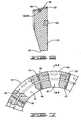
- FIG. 6is a cross section of a slip segment 114
- FIG. 7shows a plurality of slip segments 114, bonded to one another.
- Slip segments 114comprise a slip segment body 115 which is a drillable material, for example a woven mat of fiberglass, injected with epoxy and allowed to set. Other materials, for example molded phenolic can be used.
- Slip segment bodies 115have first and second side faces or side surfaces 116 and 118 and first and second end faces or surfaces 120 and 122.
- Each of slip segment bodies 115have a plurality of buttons 124 secured thereto.
- each of first and second slip rings 94 and 96have a plurality of buttons 124 extending therefrom.
- buttons 124When downhole tool 10 is moved to the set position, buttons 124 will grippingly engage casing 25 to secure tool 10 in well 15.
- Buttons 124comprise a material of sufficient hardness to partially penetrate casing 25 and may be comprised of metallic-ceramic composite or other material of sufficient strength and may be for example like those described in U. S. Patent 5,984,007 .
- Slip rings 94 and 96each comprise a plurality of individual slip segments, for example, six or eight slip segments 114 that are bonded together at side surfaces thereof such that each side surface 118 is bonded to the adjacent slip segment 114 at side surface 116 thereof.
- Each slip segment 114is bonded with an adhesive material such as for example nitrile rubber.
- FIG. 7which is a top view with cutaway portions, shows a layer of adhesive 119 between adjacent segments 114 to connect slip segments 114 together.
- Each of slip rings 94 and 96are radially expandable from the unset to the set position shown in FIG. 3 in which slip rings 94 and 96 engage casing 25.
- slip rings 94 and 96While radially expandable, comprise indivisible slip rings with connected slip segments. Such a configuration provides advantages over the prior art in that debris will not gather between slip segments and cause the tool to hang up in the well. Thus, downhole tool 10 may be run into well 15 more quickly than prior art tools.
- Each of slip segment bodies 115have grooves 125 in at least one of the end faces thereof, and in the embodiment shown in first end face 120.
- the ends of each groove 125are aligned with the ends of grooves 125 in adjacent slip segments 114.
- Grooves 125collectively define a groove 126 in each of slip rings 94 and 96.
- a retaining band 128is disposed in each of retaining grooves 126.
- Grooves 126may be of a depth such that retaining bands 128 are below the ends or end faces 120 of slip segment bodies 115.
- End 95 of slip rings 94 and 96may be defined by a layer of adhesive, which may be the same adhesive utilized to bond slip segments 114 together, and may thus be, for example, nitrile rubber.
- the end layer of adhesivemay be referred to as end layer 129.
- Retaining band 128is completely encapsulated, and therefore will not be exposed to the well, or any well fluid therein. Retaining band 128 may thus be referred to as an encapsulated, or embedded retaining band 128, since it is completely covered by end layer 129.
- an uncovered retaining bandwas disposed in a groove around the periphery or circumference of the slip ring, which exposed the retaining band to the well. Oftentimes debris can contact such a slip ring retaining band which can damage the band so that it does not adequately hold the segments together. Thus, when a tool with the prior art configuration is lowered into the well interference may occur causing delays. Because there is no danger of slip segments 114 becoming separated and is no danger that retaining bands 128 will become hung or damaged by debris, downhole tool 10 may be run more quickly and efficiently than prior art tools.
- First and second slip wedges 98 and 100are generally identical in configuration but their orientation is reversed on mandrel 32.
- Slip wedges 99have first or free end 130 and second or abutment end 132.
- the abutment end of first and second slip wedges 98 and 100abut extrusion limiters 106 and 108, respectively.
- First end 130 of first and second slip wedges 98 and 100is positioned radially between mandrel 32 and first and second slip rings 94 and 96, respectively, so that as is known in the art slip rings 94 and 96 will be urged radially outwardly when downhole tool 10 is moved from the unset to the set position.
- Abutment end 132extends radially outwardly from outer surface 34 of mandrel 32 preferably at a 90° angle so that a flat face or flat surface 134 is defined. Abutment end 132 transitions into a radially outer surface 136 with a rounded transition or rounded corner 138 such that no sharp corners exist. Radially outer surface 136 is the surface that is the greatest radial distance from mandrel 32. Slip wedges 98 and 100 may thus be referred to as bull nosed slip wedges which will energize sealing element 102 outwardly into sealing engagement with casing 25.
- the wedgesprovide a force that helps to push the extrusion limiters 106 and 108 radially outwardly to the casing, whereas standard wedges with a flat abutment surface apply an axial force only.
- Extrusion limiters 106 and 108are cup type extrusion limiters with an arcuate cross section. Extrusion limiters 106 and 108 may be bonded to sealing element 102 or may simply be positioned adjacent ends 110 and 112 of sealing element 102 and may be for example of composite and rubber molded construction. Extrusion limiters 106 and 108 may thus include a plurality of composite layers with adjacent layers of rubber therebetween. The outermost layers are preferably rubber, for example, nitrile rubber. Each composite layer may consist of woven fiberglass cloth impregnated with a resin, for example, epoxy. The extrusion limiters are laid up in flat configuration, cut into circular shapes and molded to a cup shape shown in cross section in FIG. 2 . The flat circular shapes are placed into a mold and treated under pressure to form cup shaped extrusion limiters 106 and 108.
- Downhole tool 10is lowered into the hole in an unset position and is moved to a set position shown in FIG. 3 by means known in the art.
- the slip rings 94 and 96will move radially outwardly as they ride on slip wedges 98 and 100, respectively, due to movement of mandrel 32 relative thereto.
- mandrel 32will move upwardly and spacer ring 90 will be held stationary by a setting tool of the type known in the art so that slip rings 94 and 96 begin to move outwardly until each grippingly engage casing 25.
- slip wedges 98 and 100will energize single sealing element 102 which will be compressed and which will expand radially outwardly so that it will sealingly engage casing 25 in well 15.
- Downhole well tool 10requires less setting force and less setting stroke than existing drillable tools. This is so because tool 10 utilizes single sealing element 102, whereas currently available drillable tools utilize a plurality of seals to engage and seal against casing in a well.
- drillable toolsutilize a three-piece sealing element so downhole tool 10 uses one-third less force and has one-third less stroke than typically might be required.
- known drillable four and one-half or five and one-half inch downhole tools utilizing a three-piece sealing elementgenerally require about 33,000 pounds of setting force and about a 51 ⁇ 2-inch stroke.
- Downhole tool 10will require 22,000 to 24,000 pounds of setting force and a 31 ⁇ 2 to 4-inch stroke.
- extrusion limiters 106 and 108will deform or fold outwardly. Extrusion limiters 106 and 108 will thus be moved into engagement with casing 25 and will prevent seal 102 from extruding therearound.
- Retaining bands 128are protected from being broken because they are not exposed to well fluid or debris in the well.
- the non-exposed retaining bands, in addition to slip rings 94 and 96 which have segments that are attached to one another to lessen any fluid drag and to prevent debris from hanging up between segmentsallow downhole tool 10 to be run in at higher speeds. Because there is less risk of sticking in the well due to such causes, downhole tool 10 may be run into the well much more quickly and efficiently.
- tools using segment slipsare lowered into a well at a rate of about 125 to 150 feet/minute (about 38 metres/minute to about 46 metres/minute). Tests have indicated that downhole tool 10 may be run at speeds in excess of 500 feet/minute (about 150 metres/minute).
- the thread utilized to connect head portion 62 to mandrel 32is adapted to withstand forces that may be experienced in the well and is rated for at least 10,000 psi (69 MPa), and must be able to withstand about 55,000 pounds (about 25,000 kg) of tensile downhole load for a 41 ⁇ 2 inch (11 cm) or 51 ⁇ 2 inch (14 cm) tool. Typically, threaded composites are unable to withstand such pressures.
- downhole tool 10may be used in many configurations. In the configuration shown in FIG.
- downhole tool 10may be set in the well and utilized as a frac plug simply by dropping a sealing ball or sealing plug of a type known in the art into the well so that it will engage the seat 68. Once the sealing ball is engaged, fluid may be pumped into the well and forced into a formation above downhole tool 10. Once the desired treatment has been performed above downhole tool 10, the fluid pressure may be decreased and the fluid from a formation below downhole tool 10 is allowed to pass upwardly through downhole tool 10 to the surface along with any fluid from formations thereabove.
- FIG. 4shows the upper portion of a downhole tool 10a which is identical in all respects to downhole tool 10 except that plug 86 has been positioned in annular space 80.
- plug 86has been positioned in annular space 80.
- the downhole toolis convertible from and between the frac plug configuration shown in FIG. 2 and the bridge plug configuration shown in FIG. 4 simply by unthreading head portion 62 and inserting either spacer sleeve 22 or plug 86 depending upon the configuration that is desired.
- FIG. 5shows an embodiment referred to as downhole tool 10b which is identical in all respects to that shown in FIG. 2 except that the head portion thereof, which may be referred to as head portion 62b, has a cage portion 160 to entrap a sealing ball 162. Sealing ball 162 is movable in cage portion 160. A pin or other barrier 164 extends across a bore 166 of cage portion 160 and will allow fluid flow therethrough into the bore 40 of mandrel 32. Downhole tool 10b is a frac plug and does not require a ball or other plug dropped from the surface since sealing ball 162 is carried with tool 10b into the well.
- FIGS. 2 , 4 and 5all show the use of first and second, or upper and lower extrusion limiters 106 and 108, when the downhole tool is utilized as a frac plug, the upper extrusion limiter 106 may be excluded.
Landscapes
- Life Sciences & Earth Sciences (AREA)
- Engineering & Computer Science (AREA)
- Geology (AREA)
- Mining & Mineral Resources (AREA)
- Physics & Mathematics (AREA)
- Environmental & Geological Engineering (AREA)
- Fluid Mechanics (AREA)
- General Life Sciences & Earth Sciences (AREA)
- Geochemistry & Mineralogy (AREA)
- Earth Drilling (AREA)
- Processing Of Stones Or Stones Resemblance Materials (AREA)
- Branch Pipes, Bends, And The Like (AREA)
Description
- This disclosure generally relates to tools used in oil and gas wellbores. More specifically, the disclosure relates to drillable packers and pressure isolation tools.
- In the drilling or reworking of oil wells, a great variety of downhole tools are used. Such downhole tools often have drillable components made from metallic or non-metallic materials such as soft steel, cast iron or engineering glade plastics and composite materials. For example, but not by way of limitation, it is often desirable to seal tubing or other pipe in the well when it is desired to pump a slurry down the tubing and force the slurry out into the formation. The slurry may include for example fracturing fluid. It is necessary to seal the tubing with respect to the well casing and to prevent the fluid pressure of the slurry from lifting the tubing out of the well and likewise to force the slurry into the formation if that is the desired result. Downhole tools referred to as packers, frac plugs and bridge plugs are designed for these general purposes and are well known in the art of producing oil and gas.
- Bridge plugs isolate the portion of the well below the bridge plug from the portion of the well thereabove. Thus, there is no communication from the portions above and below the bridge plug. Frac plugs, on the other hand, allow fluid flow in one direction but prevent flow in the other. For example, frac plugs set in a well may allow fluid from below the frac plug to pass upwardly therethrough but when the slurry is pumped into the well, the frac plug will not allow flow therethrough so that any fluid being pumped down the well may be forced into a formation above the frac plug. Generally, the tool is assembled as a frac plug or bridge plug. An easily disassemblable tool that can be configured as a frac plug or a bridge plug provides advantages over prior art tools. While there are some tools that are convertible, there is a continuing need for tools that may be converted between frac plugs and bridge plugs more easily and efficiently. In addition, tools that allow for high run-in speeds are desired.
US 2004/0045723 discloses methods and apparatus for a drillable bridge plug, frac plug, cement retainer, and other related downhole apparatus, including apparatus for running these downhole apparatus.WO 2004/070163 discloses inflatable packer assemblies and bridge plugs that incorporate selective components made of a composite material.- Thus, while there are a number of pressure isolation tools on the market, there is a continuing need for improved pressure isolation tools including frac plugs and bridge plugs.
- In an aspect of the invention there is provided a downhole tool as defined in claim 1. Further preferred features of the invention are defined in the dependent claims.
- A downhole tool for use in a well has a mandrel with an expandable sealing element having first and second ends disposed thereabout. The mandrel is a composite comprised of a plurality of wound layers of fiberglass filaments coated in epoxy. The downhole tool is movable from an unset position to a set position in the well in which the sealing element engages the well, and preferably engages a casing in the well. The sealing element is likewise movable from an unset to a set position. First and second extrusion limiters are positioned at the first and second ends of the sealing element. The first and second extrusion limiters may be comprised of a plurality of composite layers with rubber layers therebetween. In one embodiment, the extrusion limiters may comprise a plurality of layers of fiberglass, for example, fiberglass filaments or fibers covered with epoxy resin, with layers of rubber, for example, nitrile rubber adjacent thereto. The first and second extrusion limiters may have an arcuately shaped cross section and be molded to the sealing element.
- First and second slip wedges are likewise disposed about the mandrel. Each of the first and second slip wedges have an abutment end which abuts the first and second extrusion limiters, respectively. The abutment end of the first and second slip wedges preferably comprise a flat portion that extends radially outwardly from a mandrel outer surface and has a rounded transition from the flat portion to a radially outer surface of the slip wedge.
- First and second slip rings are disposed about the mandrel and will ride on the slip wedges so that the first and second slip wedges will expand the first and second slip rings radially outwardly to grippingly engage casing in the well in response to relative axial movement. The first and second slip rings each comprise a plurality of individual slip segments that are bonded to one another at side surfaces thereof. Each of the slip segments have end surfaces and at least one of the end surfaces has a groove therein. The grooves in the slip segments together define a retaining groove in the first and second slip rings. A retaining band is disposed in the retaining grooves in the first and second slip rings and is not exposed to fluid in the well.
- The downhole tool has a head portion that is threaded to the mandrel. The head portion may be comprised of a composite material and the threaded connection is designed to withstand load experienced in the well. In addition, the thread allows the downhole tool to be easily disassembled so that the tool may be easily converted or interchanged between a frac plug and bridge plug.
FIG. 1 schematically shows the tool in a well.FIG. 2 is a partial section view showing an embodiment of the downhole tool.FIG. 3 shows the tool in a set position.FIG. 4 shows an alternative embodiment of the upper portion of the tool.FIG. 5 is a partial cross section showing an additional embodiment.FIG. 6 shows a side view of a slip segment.FIG. 7 is an end view of adhesively connected slip segments.- Referring now to
FIG. 1 , adownhole tool 10 is shown in awell 15 which compriseswellbore 20 withcasing 25 cemented therein.Tool 10 may be lowered into well 15 on atubing 30 or may be lowered on a wireline or other means known in the art.FIG. 1 showstool 10 in its set position in the well. Downhole tool 10 comprises amandrel 32 with anouter surface 34 and inner surface 36.Mandrel 32 may be a composite mandrel constructed of a polymeric composite with continuous fibers such as glass, carbon or aramid, for example.Mandrel 32 may, for example, be a composite mandrel comprising layers of wound fiberglass filaments held together with an epoxy resin, and may be constructed by winding layers of fiberglass filaments around a forming mandrel. A plurality of fiberglass filaments may be pulled through an epoxy bath so that the filaments are coated with epoxy prior to being wound around the forming mandrel. Any number of filaments may be wound, and for example eight strands may be wound around the mandrel at a time. A plurality of eight strand sections wound around the forming mandrel and positioned adjacent to one another form a composite layer which may be referred to as a fiberglass/epoxy layer.Composite mandrel 32 comprises a plurality of the layers.Composite mandrel 32 hasbore 40 defined by inner surface 36.- Mandrel 32 has upper or
top end 42 and lower orbottom end 44. Bore 40 defines acentral flow passage 46 therethrough. Anend section 48 may comprise amule shoe 48. In the prior art, the end section or mule shoe is generally a separate piece that is connected with pins to a tubular mandrel.Mandrel 32 includesmule shoe 48 that is integrally formed therewith and thus is laid up and formed in the manner described herein.Mule shoe 48 defines an upward facingshoulder 50 thereon. Mandrel 32 has a first or upperouter diameter 52, a second or first intermediateouter diameter 54 which is a threadedouter diameter 54, a third or second intermediateinner diameter 56 and a fourth or lowerouter diameter 58.Shoulder 50 is defined by and extends between third and fourthouter diameters Threads 60 defined on threadeddiameter 54 may comprise a high strength composite buttress thread. A head orhead portion 62 is threadedly connected tomandrel 32 and thus has mating buttressthreads 64 thereon.Head portion 62 has an upper end 66 that may comprise a plug or ball seat 68.Head 62 haslower end 70 and has first, second and thirdinner diameters threads 64 are defined on thirdinner diameter 76. Secondinner diameter 74 has a magnitude greater than firstinner diameter 72 and thirdinner diameter 76 has a magnitude greater than secondinner diameter 74. Ashoulder 78 is defined by and extends between first and secondinner diameters Shoulder 78 andupper end 42 ofmandrel 32 define anannular space 80 therebetween. In the embodiment ofFIG. 2 , aspacer sleeve 82 is disposed inannular space 80.Spacer sleeve 82 has anopen bore 84 so that fluid may pass unobstructed therethrough into and through longitudinalcentral passageway 46. As will be explained in more detail,head portion 62 is easily disconnected by unthreading frommandrel 32 so that instead of spacer sleeve 82 aplug 86, which is shown inFIG. 4 may be utilized.Plug 86 will prevent flow in either direction and as such the tool depicted inFIG. 4 will act as a bridge plug.- A
spacer ring 90 is disposed aboutmandrel 32 and abutslower end 70 ofhead portion 62 so that it is axially restrained onmandrel 32.Tool 10 further comprises a pair of slip rings 92, first and second, or upper andlower slip rings mandrel 32. A pair of slip wedges 99 which may comprise first and second or upper andlower slip wedges mandrel 32.Sealing element 102, which is anexpandable sealing element 102, is disposed aboutmandrel 32 and has first andsecond extrusion limiters FIG. 2 has asingle sealing element 102 as opposed to a multiple piece packer sealing configuration. - First and second slip rings 94 and 96 each comprise a plurality of
slip segments 114.FIG. 6 is a cross section of aslip segment 114, andFIG. 7 shows a plurality ofslip segments 114, bonded to one another. Slipsegments 114 comprise aslip segment body 115 which is a drillable material, for example a woven mat of fiberglass, injected with epoxy and allowed to set. Other materials, for example molded phenolic can be used.Slip segment bodies 115 have first and second side faces orside surfaces surfaces slip segment bodies 115 have a plurality ofbuttons 124 secured thereto. Thus, each of first and second slip rings 94 and 96 have a plurality ofbuttons 124 extending therefrom. Whendownhole tool 10 is moved to the set position,buttons 124 will grippingly engagecasing 25 to securetool 10 inwell 15.Buttons 124 comprise a material of sufficient hardness to partially penetratecasing 25 and may be comprised of metallic-ceramic composite or other material of sufficient strength and may be for example like those described inU. S. Patent 5,984,007 . - Slip rings 94 and 96 each comprise a plurality of individual slip segments, for example, six or eight
slip segments 114 that are bonded together at side surfaces thereof such that eachside surface 118 is bonded to theadjacent slip segment 114 atside surface 116 thereof. Eachslip segment 114 is bonded with an adhesive material such as for example nitrile rubber.FIG. 7 , which is a top view with cutaway portions, shows a layer of adhesive 119 betweenadjacent segments 114 to connectslip segments 114 together. Each ofslip rings FIG. 3 in which slip rings 94 and 96 engagecasing 25. Becauseindividual slip segments 114 are bonded together, slip rings 94 and 96, while radially expandable, comprise indivisible slip rings with connected slip segments. Such a configuration provides advantages over the prior art in that debris will not gather between slip segments and cause the tool to hang up in the well. Thus,downhole tool 10 may be run into well 15 more quickly than prior art tools. - Each of
slip segment bodies 115 havegrooves 125 in at least one of the end faces thereof, and in the embodiment shown infirst end face 120. The ends of eachgroove 125 are aligned with the ends ofgrooves 125 inadjacent slip segments 114.Grooves 125 collectively define a groove 126 in each ofslip rings band 128 is disposed in each of retaining grooves 126. Grooves 126 may be of a depth such that retainingbands 128 are below the ends or end faces 120 ofslip segment bodies 115.End 95 ofslip rings bond slip segments 114 together, and may thus be, for example, nitrile rubber. The end layer of adhesive may be referred to as end layer 129. Retainingband 128 is completely encapsulated, and therefore will not be exposed to the well, or any well fluid therein. Retainingband 128 may thus be referred to as an encapsulated, or embeddedretaining band 128, since it is completely covered by end layer 129. In the prior art, an uncovered retaining band was disposed in a groove around the periphery or circumference of the slip ring, which exposed the retaining band to the well. Oftentimes debris can contact such a slip ring retaining band which can damage the band so that it does not adequately hold the segments together. Thus, when a tool with the prior art configuration is lowered into the well interference may occur causing delays. Because there is no danger ofslip segments 114 becoming separated and is no danger that retainingbands 128 will become hung or damaged by debris,downhole tool 10 may be run more quickly and efficiently than prior art tools. - First and
second slip wedges mandrel 32. Slip wedges 99 have first orfree end 130 and second orabutment end 132. The abutment end of first andsecond slip wedges abut extrusion limiters First end 130 of first andsecond slip wedges mandrel 32 and first and second slip rings 94 and 96, respectively, so that as is known in the art slip rings 94 and 96 will be urged radially outwardly whendownhole tool 10 is moved from the unset to the set position.Abutment end 132 extends radially outwardly fromouter surface 34 ofmandrel 32 preferably at a 90° angle so that a flat face orflat surface 134 is defined.Abutment end 132 transitions into a radiallyouter surface 136 with a rounded transition or roundedcorner 138 such that no sharp corners exist. Radiallyouter surface 136 is the surface that is the greatest radial distance frommandrel 32. Slipwedges element 102 outwardly into sealing engagement withcasing 25. Because of the curved surfaces on the bullnosed slip wedges extrusion limiters Extrusion limiters Extrusion limiters element 102 or may simply be positioned adjacent ends 110 and 112 of sealingelement 102 and may be for example of composite and rubber molded construction.Extrusion limiters FIG. 2 . The flat circular shapes are placed into a mold and treated under pressure to form cup shapedextrusion limiters Downhole tool 10 is lowered into the hole in an unset position and is moved to a set position shown inFIG. 3 by means known in the art. In the set position, the slip rings 94 and 96 will move radially outwardly as they ride onslip wedges mandrel 32 relative thereto. It is known in the art that mandrel 32 will move upwardly andspacer ring 90 will be held stationary by a setting tool of the type known in the art so that slip rings 94 and 96 begin to move outwardly until each grippingly engagecasing 25. Continued movement will ultimately causeslip wedges single sealing element 102 which will be compressed and which will expand radially outwardly so that it will sealingly engage casing 25 inwell 15.Downhole well tool 10 requires less setting force and less setting stroke than existing drillable tools. This is so becausetool 10 utilizessingle sealing element 102, whereas currently available drillable tools utilize a plurality of seals to engage and seal against casing in a well. Generally, drillable tools utilize a three-piece sealing element sodownhole tool 10 uses one-third less force and has one-third less stroke than typically might be required. For example, known drillable four and one-half or five and one-half inch downhole tools utilizing a three-piece sealing element generally require about 33,000 pounds of setting force and about a 5½-inch stroke.Downhole tool 10 will require 22,000 to 24,000 pounds of setting force and a 3½ to 4-inch stroke. Asdownhole tool 10 is set,extrusion limiters Extrusion limiters casing 25 and will prevent seal 102 from extruding therearound.- Retaining
bands 128 are protected from being broken because they are not exposed to well fluid or debris in the well. The non-exposed retaining bands, in addition toslip rings downhole tool 10 to be run in at higher speeds. Because there is less risk of sticking in the well due to such causes,downhole tool 10 may be run into the well much more quickly and efficiently. Generally, tools using segment slips are lowered into a well at a rate of about 125 to 150 feet/minute (about 38 metres/minute to about 46 metres/minute). Tests have indicated thatdownhole tool 10 may be run at speeds in excess of 500 feet/minute (about 150 metres/minute). - The thread utilized to connect
head portion 62 tomandrel 32 is adapted to withstand forces that may be experienced in the well and is rated for at least 10,000 psi (69 MPa), and must be able to withstand about 55,000 pounds (about 25,000 kg) of tensile downhole load for a 4½ inch (11 cm) or 5½ inch (14 cm) tool. Typically, threaded composites are unable to withstand such pressures. In addition, becausehead portion 62 is threadedly connected and may be easily disconnected,downhole tool 10 may be used in many configurations. In the configuration shown inFIG. 2 ,downhole tool 10 may be set in the well and utilized as a frac plug simply by dropping a sealing ball or sealing plug of a type known in the art into the well so that it will engage the seat 68. Once the sealing ball is engaged, fluid may be pumped into the well and forced into a formation abovedownhole tool 10. Once the desired treatment has been performed abovedownhole tool 10, the fluid pressure may be decreased and the fluid from a formation belowdownhole tool 10 is allowed to pass upwardly throughdownhole tool 10 to the surface along with any fluid from formations thereabove. FIG. 4 shows the upper portion of a downhole tool 10a which is identical in all respects todownhole tool 10 except thatplug 86 has been positioned inannular space 80. When tool 10a is set in the well, fluid flow in both directions is prevented so that downhole tool 10a acts as a bridge plug. As is apparent, the downhole tool is convertible from and between the frac plug configuration shown inFIG. 2 and the bridge plug configuration shown inFIG. 4 simply by unthreadinghead portion 62 and inserting either spacer sleeve 22 or plug 86 depending upon the configuration that is desired.FIG. 5 shows an embodiment referred to asdownhole tool 10b which is identical in all respects to that shown inFIG. 2 except that the head portion thereof, which may be referred to ashead portion 62b, has a cage portion 160 to entrap asealing ball 162.Sealing ball 162 is movable in cage portion 160. A pin orother barrier 164 extends across abore 166 of cage portion 160 and will allow fluid flow therethrough into thebore 40 ofmandrel 32.Downhole tool 10b is a frac plug and does not require a ball or other plug dropped from the surface since sealingball 162 is carried withtool 10b into the well. Whentool 10b is set in the hole, fluid pressure from above will cause sealingball 162 to engage theseat 168 in cage portion 160 and fluid may be forced into a formation thereabove. When treatment abovetool 10b has been completed, fluid pressure may be relieved and fluid from belowdownhole tool 10 may flow therethrough past sealingball 162 and bore 166 upwardly in the well. WhileFIGS. 2 ,4 and 5 all show the use of first and second, or upper andlower extrusion limiters upper extrusion limiter 106 may be excluded.- It will be seen therefore, that the present invention is well adapted to carry out the ends and advantages mentioned, as well as those inherent therein. While the presently preferred embodiment of the apparatus has been shown for the purposes of this disclosure, numerous changes in the arrangement and construction of parts may be made by those skilled in the art. All of such changes are encompassed within the scope of the appended claims.
Claims (15)
- A downhole tool (10) for use in a well (15) comprising: a mandrel (32); an expandable sealing element (102) disposed about the mandrel (32) for engaging the well (15) in a set position of the tool (10); a first slip ring (94) disposed about the mandrel (32) and radially expandable outwardly from an unset to a set position in which the slip ring (94) grippingly engages the well (15), the first slip ring (94) comprising a plurality of slip segments (114) having first and second side surfaces (116,118), each of the plurality of slip segments (114) being bonded with a bonding material to an adjacent slip segment (114) at the first and second side surfaces (116,118) thereof; a second slip ring (96) disposed about the mandrel (32) and expandable radially outwardly from an unset to a set position in which the second slip ring (96) grippingly engages the well (15), the second slip ring (96) comprising a plurality of slip segments (114) having first and second side surfaces (116,118), each of the plurality of slip segments (114) being bonded with the bonding material to adjacent slip segments (114) at the first and second side surfaces (116, 118) thereof; and a groove (125) defined in an end surface (120, 122) of each of the slip segments (114), wherein the grooves (125) in the slip segments (114) in the first slip ring (94) collectively define a retaining groove (126) therein, the groove (126) in the slip segments (114) in the second slip ring (96) defining a retaining groove (126) therein; and a first retaining band disposed (128) in the retaining groove (126) in the first slip ring (94); and a second retaining band (128) disposed in the retaining groove (126) in the second slip ring (96), wherein the first and second retaining bands (128) are not exposed to fluid in the well.
- A downhole tool (10) according to claim 1, wherein: the retaining bands (128) in the first and second slip rings (94, 96) are encapsulated.
- A downhole tool (10) according to claim 1 or 2, the first and second slip rings (94, 96) each comprising an end layer (129) covering the retaining bands (128), the end layer (129) comprising the bonding material used to bond the slip segments (114) together.
- A downhole tool (10) according to any preceding claim, further comprising: a sealing element (120) having first and second ends (110, 112) disposed about the mandrel and positioned between the first and second slip rings (94, 96); and first and second extrusion limiters (106, 108) contacting the first and second ends (110, 112) of the sealing element (120), the first and second extrusion limiters (106, 108) comprising a plurality of alternating layers of rubber and a fiberglass composite, wherein the first and second extrusion limiters (106, 108) have an arcuately shaped cross section in the unset position of the tool (10).
- A downhole tool (10) according to claim 4, further comprising first and second slip wedges (98, 100) disposed about the mandrel (32), each having an abutment end (132), wherein the abutment end (132) of the first and second slip wedges (98,100) abuts the first and second extrusion limiters (106, 108), preferably the abutment end (132) of each slip wedge (98, 100) comprises a flat portion (134) extending radially outwardly from a mandrel outer surface (34) and a rounded transition (138) from the flat portion (134) to a radially outer surface (136) on the slip wedge (98, 100), preferably the abutment ends (132) of the first and second slip wedges (98, 100) compress the sealing element seal and move the sealing element (102) to the set position.
- A downhole tool (10) according to claim 1, wherein the mandrel (32) is a composite mandrel (32) comprising a plurality of layers of fiberglass filaments bonded to one another with an epoxy resin; the sealing element (102) is a packer element disposed about the mandrel (32); the first and second slip rings (94, 96) are disposed about the mandrel (32) and positioned above and below the packer element, respectively; wherein the tool (10) further comprises: a head portion (62) threadedly and removably connected to the mandrel (32); and a spacer ring (90) disposed about the mandrel (32) for axially retaining the first slip ring (94), wherein a lower end (72) of the head portion (62) provides an abutment for the spacer ring (90).
- A downhole tool (10) according to claim 6, an inner surface of the head portion defining a downward facing shoulder (78) and the mandrel (32) having an upper end (42), wherein the downward facing shoulder (78) on the head portion (62) and the upper end (42) of the mandrel (42) define an annular space (80) therebetween, preferably the tool (10)further comprises a spacer sleeve (82) positioned in the annular space (80) and captured by the downward facing shoulder (78) on the head portion (62) and the upper end (42) of the mandrel (32).
- A downhole tool (10) according to claim 6 or 7, further comprising: a ball (162) movably disposed in the head portion (62b); and a barrier (164) to entrap the ball (162) in the head portion (62b), the head portion (62b) defining a ball seat (168), wherein the ball (162) will engage the ball seat (168) to prevent fluid flow through the downhole tool (10) in a first direction, and is movable by fluid pressure off the ball seat (168) to allow fluid flow in a second direction through the downhole tool (10).
- A downhole tool (10) according to claim 6, 7 or 8, further comprising a solid plug (86) disposed in the head portion (62) and trapped between the upper end (42) of the mandrel (32) and the downward facing shoulder (78) to prevent flow through the tool (10).
- A downhole tool (10) according to claim 1, wherein the mandrel (32) is comprised of a composite material; the sealing element (102) is a single packer element disposed about the mandrel (32); wherein the tool (10) further comprises a first extrusion limiter adjacent a first end of the packer element; and a second extrusion limiter adjacent a second end of the packer element, the first and second extrusion limiters comprising a plurality of layers of fiberglass and a plurality of rubber layers, wherein each fiberglass layer has a rubber layer adjacent thereto.
- A downhole tool (10) according to claim 10, wherein the fiberglass layer is comprised of fiberglass filaments bonded together with an epoxy resin.
- A downhole tool (10) according to claim 10 or 11, wherein each of the first and second extrusion limiters are arcuate in cross section in the unset position of the sealing element.
- A downhole tool (10) according to claim 1, wherein the mandrel (32) comprises a composite mandrel; the sealing element (102) is a packer element disposed about the mandrel (32); the first slip ring (94) is comprised of individual segments (114) bonded together at side surfaces (116, 118) thereof; the second slip ring (96) is comprised of individual segments (114) bonded together at side surfaces (116, 118) thereof, the first and second slip rings (94, 96) disposed about the mandrel (32) and radially expandable from an unset to a set position to grippingly engage the well (15); the tool (10) further comprising a head portion (62) threadedly connected to the mandrel (32), the mandrel having an upper end (42); wherein the head portion (62) and the upper end (42) of the mandrel (32) define an annular space (80) therebetween.
- A tool (10) according to claim 13, further comprising: a sleeve (82) having a central bore (84) to permit fluid flow therethrough received in the annular space (80) and captured by the head portion (62) and the upper end (42) of the mandrel (32).
- A tool (10) according to claim 13 or 14, further comprising a ball (162) movably trapped in the head portion (62b) for engaging a seat (168) defined by the head portion (62b), to prevent flow in one direction through the tool (10) and to allow flow in the opposite direction.
Priority Applications (1)
| Application Number | Priority Date | Filing Date | Title |
|---|---|---|---|
| PL10763841TPL2486226T3 (en) | 2009-10-05 | 2010-10-04 | Interchangeable drillable tool |
Applications Claiming Priority (2)
| Application Number | Priority Date | Filing Date | Title |
|---|---|---|---|
| US12/573,766US8408290B2 (en) | 2009-10-05 | 2009-10-05 | Interchangeable drillable tool |
| PCT/GB2010/001850WO2011042685A1 (en) | 2009-10-05 | 2010-10-04 | Interchangeable drillable tool |
Publications (2)
| Publication Number | Publication Date |
|---|---|
| EP2486226A1 EP2486226A1 (en) | 2012-08-15 |
| EP2486226B1true EP2486226B1 (en) | 2014-02-26 |
Family
ID=43242291
Family Applications (1)
| Application Number | Title | Priority Date | Filing Date |
|---|---|---|---|
| EP10763841.3ANot-in-forceEP2486226B1 (en) | 2009-10-05 | 2010-10-04 | Interchangeable drillable tool |
Country Status (9)
| Country | Link |
|---|---|
| US (1) | US8408290B2 (en) |
| EP (1) | EP2486226B1 (en) |
| CN (1) | CN102667054B (en) |
| AU (1) | AU2010304919B2 (en) |
| CA (2) | CA2776789C (en) |
| IN (1) | IN2012DN03409A (en) |
| MY (1) | MY164282A (en) |
| PL (1) | PL2486226T3 (en) |
| WO (1) | WO2011042685A1 (en) |
Families Citing this family (25)
| Publication number | Priority date | Publication date | Assignee | Title |
|---|---|---|---|---|
| US8267177B1 (en) | 2008-08-15 | 2012-09-18 | Exelis Inc. | Means for creating field configurable bridge, fracture or soluble insert plugs |
| US7900696B1 (en) | 2008-08-15 | 2011-03-08 | Itt Manufacturing Enterprises, Inc. | Downhole tool with exposable and openable flow-back vents |
| US8393388B2 (en) | 2010-08-16 | 2013-03-12 | Baker Hughes Incorporated | Retractable petal collet backup for a subterranean seal |
| US8579023B1 (en) | 2010-10-29 | 2013-11-12 | Exelis Inc. | Composite downhole tool with ratchet locking mechanism |
| US8770276B1 (en) | 2011-04-28 | 2014-07-08 | Exelis, Inc. | Downhole tool with cones and slips |
| US9598906B2 (en) | 2011-07-22 | 2017-03-21 | Scientific Drilling International, Inc. | Method and apparatus for vibrating horizontal drill string to improve weight transfer |
| US9074439B2 (en)* | 2011-08-22 | 2015-07-07 | National Boss Hog Energy Services Llc | Downhole tool and method of use |
| US9133681B2 (en)* | 2012-04-16 | 2015-09-15 | Halliburton Energy Services, Inc. | Protected retaining bands |
| US8997859B1 (en) | 2012-05-11 | 2015-04-07 | Exelis, Inc. | Downhole tool with fluted anvil |
| US9803449B2 (en)* | 2012-06-06 | 2017-10-31 | Ccdi Composites Inc. | Pin-less composite sleeve or coupling to composite mandrel or shaft connections |
| US9157288B2 (en) | 2012-07-19 | 2015-10-13 | General Plastics & Composites, L.P. | Downhole tool system and method related thereto |
| US9470060B2 (en) | 2012-09-06 | 2016-10-18 | Weatherford Technology Holdings, Llc | Standoff device for downhole tools using slip elements |
| US9169704B2 (en) | 2013-01-31 | 2015-10-27 | Halliburton Energy Services, Inc. | Expandable wedge slip for anchoring downhole tools |
| US20140262214A1 (en)* | 2013-03-15 | 2014-09-18 | Weatherford/Lamb, Inc. | Bonded Segmented Slips |
| US9441451B2 (en)* | 2013-08-01 | 2016-09-13 | Halliburton Energy Services, Inc. | Self-setting downhole tool |
| US9828816B2 (en)* | 2014-08-21 | 2017-11-28 | Baker Hughes, LLC | Shifting tool collet with axial ridge and edge relief |
| US10016918B2 (en)* | 2014-08-30 | 2018-07-10 | Weatherford Technology Holdings, Llc | Flow resistant packing element system for composite plug |
| US9845658B1 (en) | 2015-04-17 | 2017-12-19 | Albany International Corp. | Lightweight, easily drillable or millable slip for composite frac, bridge and drop ball plugs |
| CA3012819C (en)* | 2016-02-29 | 2020-12-29 | Halliburton Energy Services, Inc. | Collapsible cone for an expandable liner hanger system |
| GB2563181A (en)* | 2016-05-12 | 2018-12-05 | Halliburton Energy Services Inc | Loosely assembled wellbore isolation assembly |
| US20190078415A1 (en)* | 2017-09-12 | 2019-03-14 | Baker Hughes, A Ge Company, Llc | Single-cone bidirectional slip system |
| CN108222874B (en)* | 2017-12-08 | 2020-03-27 | 宝鸡石油机械有限责任公司 | An underground drilling tool |
| US10801300B2 (en)* | 2018-03-26 | 2020-10-13 | Exacta-Frac Energy Services, Inc. | Composite frac plug |
| US10995325B2 (en)* | 2019-03-21 | 2021-05-04 | Fornia Biosolutions, Inc. | Additional phytase variants and methods |
| US11035197B2 (en)* | 2019-09-24 | 2021-06-15 | Exacta-Frac Energy Services, Inc. | Anchoring extrusion limiter for non-retrievable packers and composite frac plug incorporating same |
Family Cites Families (107)
| Publication number | Priority date | Publication date | Assignee | Title |
|---|---|---|---|---|
| US2076313A (en)* | 1935-07-15 | 1937-04-06 | Technicraft Engineering Corp | Bridging plug and retrieving tool therefor |
| US2368928A (en)* | 1942-03-16 | 1945-02-06 | Baker Oil Tools Inc | Packing device |
| US2772740A (en)* | 1953-11-16 | 1956-12-04 | M L Mayfield | Well packer |
| US2870794A (en)* | 1954-06-10 | 1959-01-27 | Ellis B Thaxton | Pipe plugs |
| US2879851A (en)* | 1955-08-01 | 1959-03-31 | Equipment Engineers Inc | Slip mounting for well tools |
| US3216504A (en)* | 1961-04-11 | 1965-11-09 | Otis Eng Co | Plug for well conductors |
| US3077933A (en)* | 1961-09-18 | 1963-02-19 | Baker Oil Tools Inc | Tubing anchor and catcher apparatus |
| US3195643A (en)* | 1963-02-08 | 1965-07-20 | Harbison Fischer Mfg Co | Pump anchors with slips and packer |
| US3260310A (en)* | 1963-05-27 | 1966-07-12 | Brown Oil Tools | Screw-set high-pressure packer |
| US3285343A (en)* | 1964-03-11 | 1966-11-15 | Schlumberger Well Surv Corp | Permanently set bridge plug |
| US3358766A (en)* | 1965-10-11 | 1967-12-19 | Schlumberger Technology Corp | Anti-extrusion device for a well tool packing element |
| US3298440A (en)* | 1965-10-11 | 1967-01-17 | Schlumberger Well Surv Corp | Non-retrievable bridge plug |
| US3420305A (en)* | 1966-10-26 | 1969-01-07 | Otis Eng Corp | Well tools |
| US3429375A (en)* | 1966-12-02 | 1969-02-25 | Schlumberger Technology Corp | Well tool with selectively engaged anchoring means |
| US3425489A (en)* | 1967-02-08 | 1969-02-04 | Cicero C Brown | Well packer apparatus |
| US3669190A (en)* | 1970-12-21 | 1972-06-13 | Otis Eng Corp | Methods of completing a well |
| US3684010A (en)* | 1971-02-08 | 1972-08-15 | David E Young | Selectively-anchored well tools |
| US3710866A (en)* | 1971-06-21 | 1973-01-16 | Dow Chemical Co | Drag block and slip assembly |
| US3705624A (en)* | 1971-06-21 | 1972-12-12 | Dow Chemical Co | Slip and drag block assembly |
| US3802505A (en)* | 1973-05-09 | 1974-04-09 | Schlumberger Technology Corp | Latching apparatus for installing safety valves or the like in wells |
| US3860067A (en)* | 1973-08-10 | 1975-01-14 | Fletcher Rodgers | Blow out preventer |
| US3893717A (en)* | 1974-05-15 | 1975-07-08 | Putch Samuel W | Well casing hanger assembly |
| US4151875A (en)* | 1977-12-12 | 1979-05-01 | Halliburton Company | EZ disposal packer |
| US4185689A (en)* | 1978-09-05 | 1980-01-29 | Halliburton Company | Casing bridge plug with push-out pressure equalizer valve |
| US4274489A (en)* | 1979-06-11 | 1981-06-23 | The Dow Chemical Company | Retrievable bridge plug and method of setting |
| US4457369A (en)* | 1980-12-17 | 1984-07-03 | Otis Engineering Corporation | Packer for high temperature high pressure wells |
| US4573537A (en)* | 1981-05-07 | 1986-03-04 | L'garde, Inc. | Casing packer |
| US4532989A (en)* | 1981-07-01 | 1985-08-06 | Otis Engineering Corp. | Valved plug for packer |
| US4548265A (en)* | 1983-07-15 | 1985-10-22 | Baker Oil Tools, Inc. | Downhole steam packing |
| US4605063A (en)* | 1984-05-11 | 1986-08-12 | Baker Oil Tools, Inc. | Chemical injection tubing anchor-catcher |
| US4709761A (en)* | 1984-06-29 | 1987-12-01 | Otis Engineering Corporation | Well conduit joint sealing system |
| US4690220A (en)* | 1985-05-01 | 1987-09-01 | Texas Iron Works, Inc. | Tubular member anchoring arrangement and method |
| US4653588A (en)* | 1985-10-10 | 1987-03-31 | N. J. McAllister Petroleum Industries, Inc. | Valve apparatus for controlling communication between the interior of a tubular member and an inflatable element in a well bore |
| US4662453A (en)* | 1986-01-29 | 1987-05-05 | Halliburton Company | Liner screen tieback packer apparatus and method |
| US4688641A (en)* | 1986-07-25 | 1987-08-25 | Camco, Incorporated | Well packer with releasable head and method of releasing |
| US4751968A (en)* | 1986-12-10 | 1988-06-21 | Hughes Tool Company | Wellhead stabilizing member with deflecting ribs |
| US4765404A (en)* | 1987-04-13 | 1988-08-23 | Drilex Systems, Inc. | Whipstock packer assembly |
| GB8713241D0 (en)* | 1987-06-05 | 1987-07-08 | Vg Instr Group | Bakeable vacuum systems |
| US4856591A (en)* | 1988-03-23 | 1989-08-15 | Baker Hughes Incorporated | Method and apparatus for completing a non-vertical portion of a subterranean well bore |
| US4934459A (en)* | 1989-01-23 | 1990-06-19 | Baker Hughes Incorporated | Subterranean well anchoring apparatus |
| US4901794A (en)* | 1989-01-23 | 1990-02-20 | Baker Hughes Incorporated | Subterranean well anchoring apparatus |
| US4928768A (en)* | 1989-02-09 | 1990-05-29 | Baker Hughes Incorporated | Sump packer latching mechanism |
| US5271468A (en)* | 1990-04-26 | 1993-12-21 | Halliburton Company | Downhole tool apparatus with non-metallic components and methods of drilling thereof |
| US5224540A (en)* | 1990-04-26 | 1993-07-06 | Halliburton Company | Downhole tool apparatus with non-metallic components and methods of drilling thereof |
| US5390737A (en)* | 1990-04-26 | 1995-02-21 | Halliburton Company | Downhole tool with sliding valve |
| CA2017405C (en)* | 1990-05-23 | 1995-02-21 | Kenneth Richard Mcconnell | Ball and seat-type valve for downhole rod pump |
| US5058672A (en)* | 1990-08-13 | 1991-10-22 | Lindsey Completion Systems, Inc. | Landing collar and float valve assembly |
| US5058671A (en)* | 1990-08-13 | 1991-10-22 | Lindsey Completion Systems, Inc. | Pipe insert assembly |
| US5297633A (en)* | 1991-12-20 | 1994-03-29 | Snider Philip M | Inflatable packer assembly |
| US5261492A (en)* | 1992-03-31 | 1993-11-16 | Halliburton Company | Well casing apparatus and method |
| US5404956A (en)* | 1993-05-07 | 1995-04-11 | Halliburton Company | Hydraulic setting tool and method of use |
| US5488994A (en)* | 1994-08-24 | 1996-02-06 | Halliburton Company | Inflation packer method and apparatus |
| US5540279A (en)* | 1995-05-16 | 1996-07-30 | Halliburton Company | Downhole tool apparatus with non-metallic packer element retaining shoes |
| US5682952A (en)* | 1996-03-27 | 1997-11-04 | Tam International | Extendable casing circulator and method |
| US5701959A (en)* | 1996-03-29 | 1997-12-30 | Halliburton Company | Downhole tool apparatus and method of limiting packer element extrusion |
| US5718292A (en)* | 1996-07-15 | 1998-02-17 | Halliburton Company | Inflation packer method and apparatus |
| US5857520A (en)* | 1996-11-14 | 1999-01-12 | Halliburton Energy Services, Inc. | Backup shoe for well packer |
| US6283148B1 (en)* | 1996-12-17 | 2001-09-04 | Flowmore Systems, Inc. | Standing valve with a curved fin |
| US5775429A (en)* | 1997-02-03 | 1998-07-07 | Pes, Inc. | Downhole packer |
| CA2279646C (en)* | 1997-02-03 | 2006-01-17 | Bj Services Company, U.S.A. | Deployment system and apparatus for running bottomhole assemblies in wells, particularly applicable to coiled tubing operations |
| US5931229A (en)* | 1997-05-13 | 1999-08-03 | Bj Services Company | Through tubing gravel pack system and method of gravel packing |
| US5839515A (en)* | 1997-07-07 | 1998-11-24 | Halliburton Energy Services, Inc. | Slip retaining system for downhole tools |
| US5984007A (en)* | 1998-01-09 | 1999-11-16 | Halliburton Energy Services, Inc. | Chip resistant buttons for downhole tools having slip elements |
| US6167963B1 (en) | 1998-05-08 | 2001-01-02 | Baker Hughes Incorporated | Removable non-metallic bridge plug or packer |
| US6102117A (en) | 1998-05-22 | 2000-08-15 | Halliburton Energy Services, Inc. | Retrievable high pressure, high temperature packer apparatus with anti-extrusion system |
| US6241017B1 (en)* | 1998-10-19 | 2001-06-05 | Baker Hughes Incorporated | Caged slip system and release methods |
| US6648335B1 (en)* | 1998-11-03 | 2003-11-18 | Michael D. Ezell | Metal-to-metal seal assembly for oil and gas production apparatus |
| US6315041B1 (en) | 1999-04-15 | 2001-11-13 | Stephen L. Carlisle | Multi-zone isolation tool and method of stimulating and testing a subterranean well |
| US6220349B1 (en)* | 1999-05-13 | 2001-04-24 | Halliburton Energy Services, Inc. | Low pressure, high temperature composite bridge plug |
| US6474419B2 (en)* | 1999-10-04 | 2002-11-05 | Halliburton Energy Services, Inc. | Packer with equalizing valve and method of use |
| US6354372B1 (en)* | 2000-01-13 | 2002-03-12 | Carisella & Cook Ventures | Subterranean well tool and slip assembly |
| US7255178B2 (en) | 2000-06-30 | 2007-08-14 | Bj Services Company | Drillable bridge plug |
| US7600572B2 (en)* | 2000-06-30 | 2009-10-13 | Bj Services Company | Drillable bridge plug |
| US6578633B2 (en) | 2000-06-30 | 2003-06-17 | Bj Services Company | Drillable bridge plug |
| US6378606B1 (en)* | 2000-07-11 | 2002-04-30 | Halliburton Energy Services, Inc. | High temperature high pressure retrievable packer with barrel slip |
| US6394180B1 (en)* | 2000-07-12 | 2002-05-28 | Halliburton Energy Service,S Inc. | Frac plug with caged ball |
| US6598672B2 (en) | 2000-10-12 | 2003-07-29 | Greene, Tweed Of Delaware, Inc. | Anti-extrusion device for downhole applications |
| US6712153B2 (en) | 2001-06-27 | 2004-03-30 | Weatherford/Lamb, Inc. | Resin impregnated continuous fiber plug with non-metallic element system |
| US6578638B2 (en)* | 2001-08-27 | 2003-06-17 | Weatherford/Lamb, Inc. | Drillable inflatable packer & methods of use |
| CA2365218A1 (en)* | 2001-12-14 | 2003-06-14 | Vitold P. Serafin | Open hole straddle tool |
| US6793022B2 (en)* | 2002-04-04 | 2004-09-21 | Halliburton Energy Services, Inc. | Spring wire composite corrosion resistant anchoring device |
| US6695051B2 (en)* | 2002-06-10 | 2004-02-24 | Halliburton Energy Services, Inc. | Expandable retaining shoe |
| US6695050B2 (en)* | 2002-06-10 | 2004-02-24 | Halliburton Energy Services, Inc. | Expandable retaining shoe |
| GB2418216B (en)* | 2002-06-12 | 2006-10-11 | Enventure Global Technology | Collapsible expansion cone |
| US6796376B2 (en)* | 2002-07-02 | 2004-09-28 | Warren L. Frazier | Composite bridge plug system |
| US6802372B2 (en)* | 2002-07-30 | 2004-10-12 | Weatherford/Lamb, Inc. | Apparatus for releasing a ball into a wellbore |
| US7048066B2 (en) | 2002-10-09 | 2006-05-23 | Halliburton Energy Services, Inc. | Downhole sealing tools and method of use |
| US7234522B2 (en)* | 2002-12-18 | 2007-06-26 | Halliburton Energy Services, Inc. | Apparatus and method for drilling a wellbore with casing and cementing the casing in the wellbore |
| WO2004070163A1 (en) | 2003-02-03 | 2004-08-19 | Baker Hughes Incorporated | Composite inflatable downhole packer or bridge plug |
| US7017672B2 (en)* | 2003-05-02 | 2006-03-28 | Go Ii Oil Tools, Inc. | Self-set bridge plug |
| US7314089B2 (en)* | 2003-08-26 | 2008-01-01 | Weatherford/Lamb, Inc. | Method of wellbore pumping apparatus with improved temperature performance and method of use |
| US6976534B2 (en)* | 2003-09-29 | 2005-12-20 | Halliburton Energy Services, Inc. | Slip element for use with a downhole tool and a method of manufacturing same |
| US7350582B2 (en)* | 2004-12-21 | 2008-04-01 | Weatherford/Lamb, Inc. | Wellbore tool with disintegratable components and method of controlling flow |
| US7434627B2 (en) | 2005-06-14 | 2008-10-14 | Weatherford/Lamb, Inc. | Method and apparatus for friction reduction in a downhole tool |
| US7243733B2 (en)* | 2005-07-15 | 2007-07-17 | Stinger Wellhead Protection, Inc. | Cup tool for a high-pressure mandrel and method of using same |
| US20070051521A1 (en) | 2005-09-08 | 2007-03-08 | Eagle Downhole Solutions, Llc | Retrievable frac packer |
| US7434617B2 (en)* | 2006-04-05 | 2008-10-14 | Stinger Wellhead Protection, Inc. | Cup tool with three-part packoff for a high pressure mandrel |
| US7591318B2 (en)* | 2006-07-20 | 2009-09-22 | Halliburton Energy Services, Inc. | Method for removing a sealing plug from a well |
| US7373973B2 (en)* | 2006-09-13 | 2008-05-20 | Halliburton Energy Services, Inc. | Packer element retaining system |
| US7578353B2 (en)* | 2006-09-22 | 2009-08-25 | Robert Bradley Cook | Apparatus for controlling slip deployment in a downhole device |
| US7690436B2 (en)* | 2007-05-01 | 2010-04-06 | Weatherford/Lamb Inc. | Pressure isolation plug for horizontal wellbore and associated methods |
| US20090038790A1 (en) | 2007-08-09 | 2009-02-12 | Halliburton Energy Services, Inc. | Downhole tool with slip elements having a friction surface |
| US7740079B2 (en) | 2007-08-16 | 2010-06-22 | Halliburton Energy Services, Inc. | Fracturing plug convertible to a bridge plug |
| US7874356B2 (en)* | 2008-06-13 | 2011-01-25 | Schlumberger Technology Corporation | Single packer system for collecting fluid in a wellbore |
| US7967077B2 (en)* | 2008-07-17 | 2011-06-28 | Halliburton Energy Services, Inc. | Interventionless set packer and setting method for same |
| US8047279B2 (en)* | 2009-02-18 | 2011-11-01 | Halliburton Energy Services Inc. | Slip segments for downhole tool |
| US20110005779A1 (en)* | 2009-07-09 | 2011-01-13 | Weatherford/Lamb, Inc. | Composite downhole tool with reduced slip volume |
- 2009
- 2009-10-05USUS12/573,766patent/US8408290B2/enactiveActive
- 2010
- 2010-10-04CACA2776789Apatent/CA2776789C/enactiveActive
- 2010-10-04MYMYPI2012001545Apatent/MY164282A/enunknown
- 2010-10-04WOPCT/GB2010/001850patent/WO2011042685A1/enactiveApplication Filing
- 2010-10-04CNCN201080054480.XApatent/CN102667054B/ennot_activeExpired - Fee Related
- 2010-10-04CACA2848449Apatent/CA2848449C/enactiveActive
- 2010-10-04EPEP10763841.3Apatent/EP2486226B1/ennot_activeNot-in-force
- 2010-10-04PLPL10763841Tpatent/PL2486226T3/enunknown
- 2010-10-04AUAU2010304919Apatent/AU2010304919B2/ennot_activeCeased
- 2010-10-04ININ3409DEN2012patent/IN2012DN03409A/enunknown
Also Published As
| Publication number | Publication date |
|---|---|
| IN2012DN03409A (en) | 2015-10-23 |
| CN102667054B (en) | 2015-05-13 |
| MY164282A (en) | 2017-11-30 |
| AU2010304919B2 (en) | 2015-01-22 |
| CN102667054A (en) | 2012-09-12 |
| US20110079383A1 (en) | 2011-04-07 |
| PL2486226T3 (en) | 2014-08-29 |
| CA2848449A1 (en) | 2011-04-14 |
| US8408290B2 (en) | 2013-04-02 |
| EP2486226A1 (en) | 2012-08-15 |
| WO2011042685A1 (en) | 2011-04-14 |
| CA2848449C (en) | 2016-03-08 |
| WO2011042685A8 (en) | 2012-05-31 |
| CA2776789A1 (en) | 2011-04-14 |
| CA2776789C (en) | 2014-07-15 |
| AU2010304919A1 (en) | 2012-05-24 |
Similar Documents
| Publication | Publication Date | Title |
|---|---|---|
| EP2486226B1 (en) | Interchangeable drillable tool | |
| US8191625B2 (en) | Multiple layer extrusion limiter | |
| US11136855B2 (en) | Downhole tool with a slip insert having a hole | |
| US7740079B2 (en) | Fracturing plug convertible to a bridge plug | |
| US8839869B2 (en) | Composite reconfigurable tool | |
| DK2313606T3 (en) | Borehole tool with retaining ring of several materials | |
| US9169704B2 (en) | Expandable wedge slip for anchoring downhole tools | |
| US20090126945A1 (en) | Anchoring and sealing system for cased hole wells | |
| US20040244966A1 (en) | Slip system for retrievable packer | |
| EP3094813B1 (en) | Sealing element for downhole tool | |
| US8875799B2 (en) | Covered retaining shoe configurations for use in a downhole tool | |
| AU2014277763B2 (en) | Interchangeable drillable tool |
Legal Events
| Date | Code | Title | Description |
|---|---|---|---|
| PUAI | Public reference made under article 153(3) epc to a published international application that has entered the european phase | Free format text:ORIGINAL CODE: 0009012 | |
| 17P | Request for examination filed | Effective date:20120503 | |
| AK | Designated contracting states | Kind code of ref document:A1 Designated state(s):AL AT BE BG CH CY CZ DE DK EE ES FI FR GB GR HR HU IE IS IT LI LT LU LV MC MK MT NL NO PL PT RO RS SE SI SK SM TR | |
| RIN1 | Information on inventor provided before grant (corrected) | Inventor name:NEER, ADAM K. Inventor name:STANDRIDGE, WILLIAM E. Inventor name:MANKE, KEVIN R. Inventor name:PORTER, JESSE C. Inventor name:MARTIN, TRACY | |
| DAX | Request for extension of the european patent (deleted) | ||
| GRAP | Despatch of communication of intention to grant a patent | Free format text:ORIGINAL CODE: EPIDOSNIGR1 | |
| INTG | Intention to grant announced | Effective date:20130909 | |
| GRAS | Grant fee paid | Free format text:ORIGINAL CODE: EPIDOSNIGR3 | |
| GRAA | (expected) grant | Free format text:ORIGINAL CODE: 0009210 | |
| AK | Designated contracting states | Kind code of ref document:B1 Designated state(s):AL AT BE BG CH CY CZ DE DK EE ES FI FR GB GR HR HU IE IS IT LI LT LU LV MC MK MT NL NO PL PT RO RS SE SI SK SM TR | |
| REG | Reference to a national code | Ref country code:GB Ref legal event code:FG4D | |
| REG | Reference to a national code | Ref country code:CH Ref legal event code:EP | |
| REG | Reference to a national code | Ref country code:AT Ref legal event code:REF Ref document number:653745 Country of ref document:AT Kind code of ref document:T Effective date:20140315 | |
| REG | Reference to a national code | Ref country code:IE Ref legal event code:FG4D | |
| REG | Reference to a national code | Ref country code:DE Ref legal event code:R096 Ref document number:602010013799 Country of ref document:DE Effective date:20140410 | |
| REG | Reference to a national code | Ref country code:NL Ref legal event code:VDEP Effective date:20140226 | |
| REG | Reference to a national code | Ref country code:AT Ref legal event code:MK05 Ref document number:653745 Country of ref document:AT Kind code of ref document:T Effective date:20140226 | |
| REG | Reference to a national code | Ref country code:LT Ref legal event code:MG4D | |
| REG | Reference to a national code | Ref country code:NO Ref legal event code:T2 Effective date:20140226 | |
| PG25 | Lapsed in a contracting state [announced via postgrant information from national office to epo] | Ref country code:LT Free format text:LAPSE BECAUSE OF FAILURE TO SUBMIT A TRANSLATION OF THE DESCRIPTION OR TO PAY THE FEE WITHIN THE PRESCRIBED TIME-LIMIT Effective date:20140226 Ref country code:IS Free format text:LAPSE BECAUSE OF FAILURE TO SUBMIT A TRANSLATION OF THE DESCRIPTION OR TO PAY THE FEE WITHIN THE PRESCRIBED TIME-LIMIT Effective date:20140626 | |
| PG25 | Lapsed in a contracting state [announced via postgrant information from national office to epo] | Ref country code:PT Free format text:LAPSE BECAUSE OF FAILURE TO SUBMIT A TRANSLATION OF THE DESCRIPTION OR TO PAY THE FEE WITHIN THE PRESCRIBED TIME-LIMIT Effective date:20140626 Ref country code:CY Free format text:LAPSE BECAUSE OF FAILURE TO SUBMIT A TRANSLATION OF THE DESCRIPTION OR TO PAY THE FEE WITHIN THE PRESCRIBED TIME-LIMIT Effective date:20140226 Ref country code:NL Free format text:LAPSE BECAUSE OF FAILURE TO SUBMIT A TRANSLATION OF THE DESCRIPTION OR TO PAY THE FEE WITHIN THE PRESCRIBED TIME-LIMIT Effective date:20140226 Ref country code:FI Free format text:LAPSE BECAUSE OF FAILURE TO SUBMIT A TRANSLATION OF THE DESCRIPTION OR TO PAY THE FEE WITHIN THE PRESCRIBED TIME-LIMIT Effective date:20140226 Ref country code:AT Free format text:LAPSE BECAUSE OF FAILURE TO SUBMIT A TRANSLATION OF THE DESCRIPTION OR TO PAY THE FEE WITHIN THE PRESCRIBED TIME-LIMIT Effective date:20140226 Ref country code:SE Free format text:LAPSE BECAUSE OF FAILURE TO SUBMIT A TRANSLATION OF THE DESCRIPTION OR TO PAY THE FEE WITHIN THE PRESCRIBED TIME-LIMIT Effective date:20140226 | |
| REG | Reference to a national code | Ref country code:PL Ref legal event code:T3 | |
| PG25 | Lapsed in a contracting state [announced via postgrant information from national office to epo] | Ref country code:LV Free format text:LAPSE BECAUSE OF FAILURE TO SUBMIT A TRANSLATION OF THE DESCRIPTION OR TO PAY THE FEE WITHIN THE PRESCRIBED TIME-LIMIT Effective date:20140226 Ref country code:HR Free format text:LAPSE BECAUSE OF FAILURE TO SUBMIT A TRANSLATION OF THE DESCRIPTION OR TO PAY THE FEE WITHIN THE PRESCRIBED TIME-LIMIT Effective date:20140226 Ref country code:BE Free format text:LAPSE BECAUSE OF FAILURE TO SUBMIT A TRANSLATION OF THE DESCRIPTION OR TO PAY THE FEE WITHIN THE PRESCRIBED TIME-LIMIT Effective date:20140226 Ref country code:RS Free format text:LAPSE BECAUSE OF FAILURE TO SUBMIT A TRANSLATION OF THE DESCRIPTION OR TO PAY THE FEE WITHIN THE PRESCRIBED TIME-LIMIT Effective date:20140226 | |
| PG25 | Lapsed in a contracting state [announced via postgrant information from national office to epo] | Ref country code:RO Free format text:LAPSE BECAUSE OF FAILURE TO SUBMIT A TRANSLATION OF THE DESCRIPTION OR TO PAY THE FEE WITHIN THE PRESCRIBED TIME-LIMIT Effective date:20140226 Ref country code:EE Free format text:LAPSE BECAUSE OF FAILURE TO SUBMIT A TRANSLATION OF THE DESCRIPTION OR TO PAY THE FEE WITHIN THE PRESCRIBED TIME-LIMIT Effective date:20140226 Ref country code:CZ Free format text:LAPSE BECAUSE OF FAILURE TO SUBMIT A TRANSLATION OF THE DESCRIPTION OR TO PAY THE FEE WITHIN THE PRESCRIBED TIME-LIMIT Effective date:20140226 Ref country code:DK Free format text:LAPSE BECAUSE OF FAILURE TO SUBMIT A TRANSLATION OF THE DESCRIPTION OR TO PAY THE FEE WITHIN THE PRESCRIBED TIME-LIMIT Effective date:20140226 | |
| REG | Reference to a national code | Ref country code:DE Ref legal event code:R097 Ref document number:602010013799 Country of ref document:DE | |
| PG25 | Lapsed in a contracting state [announced via postgrant information from national office to epo] | Ref country code:SK Free format text:LAPSE BECAUSE OF FAILURE TO SUBMIT A TRANSLATION OF THE DESCRIPTION OR TO PAY THE FEE WITHIN THE PRESCRIBED TIME-LIMIT Effective date:20140226 Ref country code:ES Free format text:LAPSE BECAUSE OF FAILURE TO SUBMIT A TRANSLATION OF THE DESCRIPTION OR TO PAY THE FEE WITHIN THE PRESCRIBED TIME-LIMIT Effective date:20140226 | |
| PGFP | Annual fee paid to national office [announced via postgrant information from national office to epo] | Ref country code:PL Payment date:20140923 Year of fee payment:5 Ref country code:GB Payment date:20140925 Year of fee payment:5 | |
| PLBE | No opposition filed within time limit | Free format text:ORIGINAL CODE: 0009261 | |
| STAA | Information on the status of an ep patent application or granted ep patent | Free format text:STATUS: NO OPPOSITION FILED WITHIN TIME LIMIT | |
| PGFP | Annual fee paid to national office [announced via postgrant information from national office to epo] | Ref country code:DE Payment date:20141028 Year of fee payment:5 | |
| 26N | No opposition filed | Effective date:20141127 | |
| REG | Reference to a national code | Ref country code:DE Ref legal event code:R097 Ref document number:602010013799 Country of ref document:DE Effective date:20141127 | |
| PGFP | Annual fee paid to national office [announced via postgrant information from national office to epo] | Ref country code:IT Payment date:20141014 Year of fee payment:5 | |
| PG25 | Lapsed in a contracting state [announced via postgrant information from national office to epo] | Ref country code:SI Free format text:LAPSE BECAUSE OF FAILURE TO SUBMIT A TRANSLATION OF THE DESCRIPTION OR TO PAY THE FEE WITHIN THE PRESCRIBED TIME-LIMIT Effective date:20140226 Ref country code:LU Free format text:LAPSE BECAUSE OF FAILURE TO SUBMIT A TRANSLATION OF THE DESCRIPTION OR TO PAY THE FEE WITHIN THE PRESCRIBED TIME-LIMIT Effective date:20141004 Ref country code:MC Free format text:LAPSE BECAUSE OF FAILURE TO SUBMIT A TRANSLATION OF THE DESCRIPTION OR TO PAY THE FEE WITHIN THE PRESCRIBED TIME-LIMIT Effective date:20140226 | |
| REG | Reference to a national code | Ref country code:CH Ref legal event code:PL | |
| REG | Reference to a national code | Ref country code:IE Ref legal event code:MM4A | |
| PG25 | Lapsed in a contracting state [announced via postgrant information from national office to epo] | Ref country code:CH Free format text:LAPSE BECAUSE OF NON-PAYMENT OF DUE FEES Effective date:20141031 Ref country code:LI Free format text:LAPSE BECAUSE OF NON-PAYMENT OF DUE FEES Effective date:20141031 | |
| REG | Reference to a national code | Ref country code:FR Ref legal event code:ST Effective date:20150630 | |
| PG25 | Lapsed in a contracting state [announced via postgrant information from national office to epo] | Ref country code:FR Free format text:LAPSE BECAUSE OF NON-PAYMENT OF DUE FEES Effective date:20141031 | |
| PG25 | Lapsed in a contracting state [announced via postgrant information from national office to epo] | Ref country code:IE Free format text:LAPSE BECAUSE OF NON-PAYMENT OF DUE FEES Effective date:20141004 | |
| PGFP | Annual fee paid to national office [announced via postgrant information from national office to epo] | Ref country code:NO Payment date:20150925 Year of fee payment:6 | |
| PG25 | Lapsed in a contracting state [announced via postgrant information from national office to epo] | Ref country code:SM Free format text:LAPSE BECAUSE OF FAILURE TO SUBMIT A TRANSLATION OF THE DESCRIPTION OR TO PAY THE FEE WITHIN THE PRESCRIBED TIME-LIMIT Effective date:20140226 | |
| REG | Reference to a national code | Ref country code:DE Ref legal event code:R119 Ref document number:602010013799 Country of ref document:DE | |
| GBPC | Gb: european patent ceased through non-payment of renewal fee | Effective date:20151004 | |
| PG25 | Lapsed in a contracting state [announced via postgrant information from national office to epo] | Ref country code:GR Free format text:LAPSE BECAUSE OF FAILURE TO SUBMIT A TRANSLATION OF THE DESCRIPTION OR TO PAY THE FEE WITHIN THE PRESCRIBED TIME-LIMIT Effective date:20140527 Ref country code:BG Free format text:LAPSE BECAUSE OF FAILURE TO SUBMIT A TRANSLATION OF THE DESCRIPTION OR TO PAY THE FEE WITHIN THE PRESCRIBED TIME-LIMIT Effective date:20140226 | |
| PG25 | Lapsed in a contracting state [announced via postgrant information from national office to epo] | Ref country code:IT Free format text:LAPSE BECAUSE OF NON-PAYMENT OF DUE FEES Effective date:20151004 Ref country code:DE Free format text:LAPSE BECAUSE OF NON-PAYMENT OF DUE FEES Effective date:20160503 Ref country code:TR Free format text:LAPSE BECAUSE OF FAILURE TO SUBMIT A TRANSLATION OF THE DESCRIPTION OR TO PAY THE FEE WITHIN THE PRESCRIBED TIME-LIMIT Effective date:20140226 Ref country code:HU Free format text:LAPSE BECAUSE OF FAILURE TO SUBMIT A TRANSLATION OF THE DESCRIPTION OR TO PAY THE FEE WITHIN THE PRESCRIBED TIME-LIMIT; INVALID AB INITIO Effective date:20101004 Ref country code:GB Free format text:LAPSE BECAUSE OF NON-PAYMENT OF DUE FEES Effective date:20151004 Ref country code:MT Free format text:LAPSE BECAUSE OF FAILURE TO SUBMIT A TRANSLATION OF THE DESCRIPTION OR TO PAY THE FEE WITHIN THE PRESCRIBED TIME-LIMIT Effective date:20140226 | |
| PG25 | Lapsed in a contracting state [announced via postgrant information from national office to epo] | Ref country code:PL Free format text:LAPSE BECAUSE OF NON-PAYMENT OF DUE FEES Effective date:20151004 | |
| REG | Reference to a national code | Ref country code:NO Ref legal event code:MMEP | |
| PG25 | Lapsed in a contracting state [announced via postgrant information from national office to epo] | Ref country code:NO Free format text:LAPSE BECAUSE OF NON-PAYMENT OF DUE FEES Effective date:20161031 | |
| PG25 | Lapsed in a contracting state [announced via postgrant information from national office to epo] | Ref country code:MK Free format text:LAPSE BECAUSE OF FAILURE TO SUBMIT A TRANSLATION OF THE DESCRIPTION OR TO PAY THE FEE WITHIN THE PRESCRIBED TIME-LIMIT Effective date:20140226 | |
| PG25 | Lapsed in a contracting state [announced via postgrant information from national office to epo] | Ref country code:AL Free format text:LAPSE BECAUSE OF FAILURE TO SUBMIT A TRANSLATION OF THE DESCRIPTION OR TO PAY THE FEE WITHIN THE PRESCRIBED TIME-LIMIT Effective date:20140226 |