EP2484309B1 - Heart valve prosthesis - Google Patents
Heart valve prosthesisDownload PDFInfo
- Publication number
- EP2484309B1 EP2484309B1EP11153114.1AEP11153114AEP2484309B1EP 2484309 B1EP2484309 B1EP 2484309B1EP 11153114 AEP11153114 AEP 11153114AEP 2484309 B1EP2484309 B1EP 2484309B1
- Authority
- EP
- European Patent Office
- Prior art keywords
- valve
- inflow
- prosthesis
- outflow
- support member
- Prior art date
- Legal status (The legal status is an assumption and is not a legal conclusion. Google has not performed a legal analysis and makes no representation as to the accuracy of the status listed.)
- Revoked
Links
- 210000003709heart valveAnatomy0.000titleclaimsdescription41
- 238000002513implantationMethods0.000claimsdescription25
- 239000000560biocompatible materialSubstances0.000claimsdescription8
- 239000008280bloodSubstances0.000claimsdescription7
- 210000004369bloodAnatomy0.000claimsdescription7
- 241001465754MetazoaSpecies0.000claimsdescription6
- 238000000034methodMethods0.000description22
- 210000001519tissueAnatomy0.000description16
- 210000002216heartAnatomy0.000description14
- 210000004115mitral valveAnatomy0.000description14
- 239000000463materialSubstances0.000description8
- 210000001008atrial appendageAnatomy0.000description5
- 238000003780insertionMethods0.000description5
- 230000037431insertionEffects0.000description5
- 239000012620biological materialSubstances0.000description4
- 230000002612cardiopulmonary effectEffects0.000description4
- 210000005248left atrial appendageAnatomy0.000description3
- 230000007246mechanismEffects0.000description3
- 210000004165myocardiumAnatomy0.000description3
- 210000003516pericardiumAnatomy0.000description3
- 241001269524DuraSpecies0.000description2
- SXRSQZLOMIGNAQ-UHFFFAOYSA-NGlutaraldehydeChemical compoundO=CCCCC=OSXRSQZLOMIGNAQ-UHFFFAOYSA-N0.000description2
- 239000000956alloySubstances0.000description2
- 210000001765aortic valveAnatomy0.000description2
- 229910001000nickel titaniumInorganic materials0.000description2
- 229920000642polymerPolymers0.000description2
- 230000008569processEffects0.000description2
- 229910001285shape-memory alloyInorganic materials0.000description2
- 241000283690Bos taurusSpecies0.000description1
- 241000283073Equus caballusSpecies0.000description1
- MWCLLHOVUTZFKS-UHFFFAOYSA-NMethyl cyanoacrylateChemical compoundCOC(=O)C(=C)C#NMWCLLHOVUTZFKS-UHFFFAOYSA-N0.000description1
- 208000007536ThrombosisDiseases0.000description1
- 230000001154acute effectEffects0.000description1
- 239000000853adhesiveSubstances0.000description1
- 230000001070adhesive effectEffects0.000description1
- 229910045601alloyInorganic materials0.000description1
- 230000004075alterationEffects0.000description1
- 230000003872anastomosisEffects0.000description1
- 238000004873anchoringMethods0.000description1
- 238000013459approachMethods0.000description1
- 230000003190augmentative effectEffects0.000description1
- 230000015572biosynthetic processEffects0.000description1
- 230000000740bleeding effectEffects0.000description1
- 230000017531blood circulationEffects0.000description1
- 230000002308calcificationEffects0.000description1
- 239000002131composite materialSubstances0.000description1
- 238000001816coolingMethods0.000description1
- 238000001784detoxificationMethods0.000description1
- 201000010099diseaseDiseases0.000description1
- 208000037265diseases, disorders, signs and symptomsDiseases0.000description1
- 230000004064dysfunctionEffects0.000description1
- 230000001747exhibiting effectEffects0.000description1
- 210000003191femoral veinAnatomy0.000description1
- 239000012530fluidSubstances0.000description1
- 238000002594fluoroscopyMethods0.000description1
- 230000006870functionEffects0.000description1
- 238000010438heat treatmentMethods0.000description1
- 230000000004hemodynamic effectEffects0.000description1
- 229960002897heparinDrugs0.000description1
- 229920000669heparinPolymers0.000description1
- 238000003384imaging methodMethods0.000description1
- 238000011065in-situ storageMethods0.000description1
- 229910000734martensiteInorganic materials0.000description1
- 238000002324minimally invasive surgeryMethods0.000description1
- 239000000203mixtureSubstances0.000description1
- 238000012986modificationMethods0.000description1
- 230000004048modificationEffects0.000description1
- 239000003607modifierSubstances0.000description1
- 239000005445natural materialSubstances0.000description1
- HLXZNVUGXRDIFK-UHFFFAOYSA-Nnickel titaniumChemical compound[Ti].[Ti].[Ti].[Ti].[Ti].[Ti].[Ti].[Ti].[Ti].[Ti].[Ti].[Ni].[Ni].[Ni].[Ni].[Ni].[Ni].[Ni].[Ni].[Ni].[Ni].[Ni].[Ni].[Ni].[Ni]HLXZNVUGXRDIFK-UHFFFAOYSA-N0.000description1
- 239000004810polytetrafluoroethyleneSubstances0.000description1
- 229920001343polytetrafluoroethylenePolymers0.000description1
- 230000000717retained effectEffects0.000description1
- 239000003894surgical glueSubstances0.000description1
- 238000001356surgical procedureMethods0.000description1
- 229920002994synthetic fiberPolymers0.000description1
- 230000009466transformationEffects0.000description1
- 210000002073venous valveAnatomy0.000description1
- XLYOFNOQVPJJNP-UHFFFAOYSA-NwaterSubstancesOXLYOFNOQVPJJNP-UHFFFAOYSA-N0.000description1
Images


Classifications
- A—HUMAN NECESSITIES
- A61—MEDICAL OR VETERINARY SCIENCE; HYGIENE
- A61F—FILTERS IMPLANTABLE INTO BLOOD VESSELS; PROSTHESES; DEVICES PROVIDING PATENCY TO, OR PREVENTING COLLAPSING OF, TUBULAR STRUCTURES OF THE BODY, e.g. STENTS; ORTHOPAEDIC, NURSING OR CONTRACEPTIVE DEVICES; FOMENTATION; TREATMENT OR PROTECTION OF EYES OR EARS; BANDAGES, DRESSINGS OR ABSORBENT PADS; FIRST-AID KITS
- A61F2/00—Filters implantable into blood vessels; Prostheses, i.e. artificial substitutes or replacements for parts of the body; Appliances for connecting them with the body; Devices providing patency to, or preventing collapsing of, tubular structures of the body, e.g. stents
- A61F2/02—Prostheses implantable into the body
- A61F2/24—Heart valves ; Vascular valves, e.g. venous valves; Heart implants, e.g. passive devices for improving the function of the native valve or the heart muscle; Transmyocardial revascularisation [TMR] devices; Valves implantable in the body
- A61F2/2412—Heart valves ; Vascular valves, e.g. venous valves; Heart implants, e.g. passive devices for improving the function of the native valve or the heart muscle; Transmyocardial revascularisation [TMR] devices; Valves implantable in the body with soft flexible valve members, e.g. tissue valves shaped like natural valves
- A61F2/2418—Scaffolds therefor, e.g. support stents
- A—HUMAN NECESSITIES
- A61—MEDICAL OR VETERINARY SCIENCE; HYGIENE
- A61F—FILTERS IMPLANTABLE INTO BLOOD VESSELS; PROSTHESES; DEVICES PROVIDING PATENCY TO, OR PREVENTING COLLAPSING OF, TUBULAR STRUCTURES OF THE BODY, e.g. STENTS; ORTHOPAEDIC, NURSING OR CONTRACEPTIVE DEVICES; FOMENTATION; TREATMENT OR PROTECTION OF EYES OR EARS; BANDAGES, DRESSINGS OR ABSORBENT PADS; FIRST-AID KITS
- A61F2220/00—Fixations or connections for prostheses classified in groups A61F2/00 - A61F2/26 or A61F2/82 or A61F9/00 or A61F11/00 or subgroups thereof
- A61F2220/0008—Fixation appliances for connecting prostheses to the body
- A61F2220/0016—Fixation appliances for connecting prostheses to the body with sharp anchoring protrusions, e.g. barbs, pins, spikes
- A—HUMAN NECESSITIES
- A61—MEDICAL OR VETERINARY SCIENCE; HYGIENE
- A61F—FILTERS IMPLANTABLE INTO BLOOD VESSELS; PROSTHESES; DEVICES PROVIDING PATENCY TO, OR PREVENTING COLLAPSING OF, TUBULAR STRUCTURES OF THE BODY, e.g. STENTS; ORTHOPAEDIC, NURSING OR CONTRACEPTIVE DEVICES; FOMENTATION; TREATMENT OR PROTECTION OF EYES OR EARS; BANDAGES, DRESSINGS OR ABSORBENT PADS; FIRST-AID KITS
- A61F2220/00—Fixations or connections for prostheses classified in groups A61F2/00 - A61F2/26 or A61F2/82 or A61F9/00 or A61F11/00 or subgroups thereof
- A61F2220/0025—Connections or couplings between prosthetic parts, e.g. between modular parts; Connecting elements
- A61F2220/005—Connections or couplings between prosthetic parts, e.g. between modular parts; Connecting elements using adhesives
- A—HUMAN NECESSITIES
- A61—MEDICAL OR VETERINARY SCIENCE; HYGIENE
- A61F—FILTERS IMPLANTABLE INTO BLOOD VESSELS; PROSTHESES; DEVICES PROVIDING PATENCY TO, OR PREVENTING COLLAPSING OF, TUBULAR STRUCTURES OF THE BODY, e.g. STENTS; ORTHOPAEDIC, NURSING OR CONTRACEPTIVE DEVICES; FOMENTATION; TREATMENT OR PROTECTION OF EYES OR EARS; BANDAGES, DRESSINGS OR ABSORBENT PADS; FIRST-AID KITS
- A61F2220/00—Fixations or connections for prostheses classified in groups A61F2/00 - A61F2/26 or A61F2/82 or A61F9/00 or A61F11/00 or subgroups thereof
- A61F2220/0025—Connections or couplings between prosthetic parts, e.g. between modular parts; Connecting elements
- A61F2220/0066—Connections or couplings between prosthetic parts, e.g. between modular parts; Connecting elements stapled
- A—HUMAN NECESSITIES
- A61—MEDICAL OR VETERINARY SCIENCE; HYGIENE
- A61F—FILTERS IMPLANTABLE INTO BLOOD VESSELS; PROSTHESES; DEVICES PROVIDING PATENCY TO, OR PREVENTING COLLAPSING OF, TUBULAR STRUCTURES OF THE BODY, e.g. STENTS; ORTHOPAEDIC, NURSING OR CONTRACEPTIVE DEVICES; FOMENTATION; TREATMENT OR PROTECTION OF EYES OR EARS; BANDAGES, DRESSINGS OR ABSORBENT PADS; FIRST-AID KITS
- A61F2220/00—Fixations or connections for prostheses classified in groups A61F2/00 - A61F2/26 or A61F2/82 or A61F9/00 or A61F11/00 or subgroups thereof
- A61F2220/0025—Connections or couplings between prosthetic parts, e.g. between modular parts; Connecting elements
- A61F2220/0075—Connections or couplings between prosthetic parts, e.g. between modular parts; Connecting elements sutured, ligatured or stitched, retained or tied with a rope, string, thread, wire or cable
- A—HUMAN NECESSITIES
- A61—MEDICAL OR VETERINARY SCIENCE; HYGIENE
- A61F—FILTERS IMPLANTABLE INTO BLOOD VESSELS; PROSTHESES; DEVICES PROVIDING PATENCY TO, OR PREVENTING COLLAPSING OF, TUBULAR STRUCTURES OF THE BODY, e.g. STENTS; ORTHOPAEDIC, NURSING OR CONTRACEPTIVE DEVICES; FOMENTATION; TREATMENT OR PROTECTION OF EYES OR EARS; BANDAGES, DRESSINGS OR ABSORBENT PADS; FIRST-AID KITS
- A61F2230/00—Geometry of prostheses classified in groups A61F2/00 - A61F2/26 or A61F2/82 or A61F9/00 or A61F11/00 or subgroups thereof
- A61F2230/0002—Two-dimensional shapes, e.g. cross-sections
- A61F2230/0017—Angular shapes
- A—HUMAN NECESSITIES
- A61—MEDICAL OR VETERINARY SCIENCE; HYGIENE
- A61F—FILTERS IMPLANTABLE INTO BLOOD VESSELS; PROSTHESES; DEVICES PROVIDING PATENCY TO, OR PREVENTING COLLAPSING OF, TUBULAR STRUCTURES OF THE BODY, e.g. STENTS; ORTHOPAEDIC, NURSING OR CONTRACEPTIVE DEVICES; FOMENTATION; TREATMENT OR PROTECTION OF EYES OR EARS; BANDAGES, DRESSINGS OR ABSORBENT PADS; FIRST-AID KITS
- A61F2230/00—Geometry of prostheses classified in groups A61F2/00 - A61F2/26 or A61F2/82 or A61F9/00 or A61F11/00 or subgroups thereof
- A61F2230/0002—Two-dimensional shapes, e.g. cross-sections
- A61F2230/0028—Shapes in the form of latin or greek characters
- A61F2230/0054—V-shaped
- A—HUMAN NECESSITIES
- A61—MEDICAL OR VETERINARY SCIENCE; HYGIENE
- A61F—FILTERS IMPLANTABLE INTO BLOOD VESSELS; PROSTHESES; DEVICES PROVIDING PATENCY TO, OR PREVENTING COLLAPSING OF, TUBULAR STRUCTURES OF THE BODY, e.g. STENTS; ORTHOPAEDIC, NURSING OR CONTRACEPTIVE DEVICES; FOMENTATION; TREATMENT OR PROTECTION OF EYES OR EARS; BANDAGES, DRESSINGS OR ABSORBENT PADS; FIRST-AID KITS
- A61F2230/00—Geometry of prostheses classified in groups A61F2/00 - A61F2/26 or A61F2/82 or A61F9/00 or A61F11/00 or subgroups thereof
- A61F2230/0063—Three-dimensional shapes
- A61F2230/0073—Quadric-shaped
- A61F2230/0078—Quadric-shaped hyperboloidal
- A—HUMAN NECESSITIES
- A61—MEDICAL OR VETERINARY SCIENCE; HYGIENE
- A61F—FILTERS IMPLANTABLE INTO BLOOD VESSELS; PROSTHESES; DEVICES PROVIDING PATENCY TO, OR PREVENTING COLLAPSING OF, TUBULAR STRUCTURES OF THE BODY, e.g. STENTS; ORTHOPAEDIC, NURSING OR CONTRACEPTIVE DEVICES; FOMENTATION; TREATMENT OR PROTECTION OF EYES OR EARS; BANDAGES, DRESSINGS OR ABSORBENT PADS; FIRST-AID KITS
- A61F2250/00—Special features of prostheses classified in groups A61F2/00 - A61F2/26 or A61F2/82 or A61F9/00 or A61F11/00 or subgroups thereof
- A61F2250/0004—Special features of prostheses classified in groups A61F2/00 - A61F2/26 or A61F2/82 or A61F9/00 or A61F11/00 or subgroups thereof adjustable
- A61F2250/001—Special features of prostheses classified in groups A61F2/00 - A61F2/26 or A61F2/82 or A61F9/00 or A61F11/00 or subgroups thereof adjustable for adjusting a diameter
Definitions
- the present inventionrelates to a heart valve prosthesis.
- Heart valve replacementoffers requires open heart surgery, although more minimally invasive procedures (e.g., percutaneous implantation) may be utilized for replacing certain valves.
- Heart valve prosthesestypically are either mechanical valve designs or biological designs. The type of heart valve prosthesis and method of implantation are often dictated according to which valve requires replacement and the size of the valve. For example, a mitral valve is often larger than 23 millimeters, making various mechanical and many types of pericardial valves inadequate for replacement. Additionally, because of the large size, in order to have a functioning and effective replacement valve, the replacement procedure cannot be done percutaneously or using a traditional catheter.
- EP 2 248 486relates to a device for occluding a hole in a body wall; among the several embodiments, it describes a heart valve prosthesis comprising a supported valve and a fixation element formed by two conical stents for a stent carrying a valve.
- US 2008/208327describes a percutaneously delivered adapter stent that is deployed within a previous implanted prosthetic valve and serves as an anchor or platform for implanting a percutaneously delivered replacement valve within the previously implanted valve.
- WO 2010/127041describes an apparatus for replacing a native cardiac valve.
- the cardiac valvehas at least one leaflet and is surrounded by native cardiac valve annulus having superior and inferior aspects.
- the apparatuscomprises a barbell-shaped expandable anchoring member.
- US 2006/271166describes a stent-less support structure capable of being at least partially assembled in situ.
- the support structurecomprises a braided tube that is very flexible and when elongated becomes very long and very small in diameter.
- US 2002/032481describes a heart valve prosthesis mounted within a support apparatus that is deformable between a first condition and a second condition.
- the prosthesishas a cross-sectional dimension in the second position that is less than a cross-sectional dimension of the supported valve when in first condition.
- the present inventionrelates to a heart valve prosthesis as defined by the appended claims. Methods of implanting the prosthesis, such as at the mitral or aortic position are also described.
- a heart valve prosthesiscomprising a supported valve that includes a biological valve portion mounted within a support structure.
- the supported valveis configured to provide for substantially unidirectional flow of blood through the supported valve.
- the supported valvehas inflow and outflow ends that are spaced axially apart from each other.
- a fixation support memberincludes inflow and outflow portions.
- the inflow portion of the fixation support memberextends from a radially inner contact surface of the fixation support member radially outwardly and axially in a direction of the inflow end of the supported valve.
- the outflow portion of the fixation support memberextends from the radially inner contact surface radially outwardly and axially in a direction away from the inflow portion of the fixation support member.
- the radially inner contact surfaceis attached to a radially outer surface of the supported valve adjacent the inflow end of the supported valve.
- the supported valve and the fixation support memberare deformable between a reduced cross-sectional dimension and an expanded cross-sectional dimension thereof, whereby implantation of the heart valve prosthesis is facilitated.
- a valve annuluse.g., a mitral valve annulus or aortic valve annulus
- the inventionrelates generally to a heart valve prosthesis according to claim 1 that includes a fixation support member dimensioned and configured to facilitate implantation using low invasive procedures.
- the prosthesisis well suited for implantation at an atrio-ventricular position.
- the prosthesiscan be made in larger sizes (e.g., greater than 24 mm) often required for mitral valve replacement.
- the prosthesiscan also be utilized for replacement of the aortic valve.
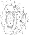
- Fig. 1depicts an example of support structures 10 and 12 that can be utilized in a heart valve prosthesis.
- the support structure 10is utilized to anchor or help hold the prosthesis in a desired axial position relative to the heart valve annulus when implanted.
- the support structure 12is utilized to support the valve in a desired orientation, which support can vary according to the type and configuration of heart valve implemented in the prosthesis.
- the support structure 10is utilized to form a fixation support member 14, such as shown in Fig. 2
- the support structure 12can be utilized (e.g., as a stent) to support a valve portion and provide a supported heart valve 16, as shown in Fig. 2 .
- the support structure 10may be referred to as a fixation support structure and the support structure 12 may be referred to as a valve support, such as a stent.
- the fixation support structure 10can be implemented as a flexible and deformable annular support that can be deformed to a reduced cross-sectional dimension and then expanded to its original, fully expanded, cross-sectional dimension, such as shown in Fig. 1 .
- the fixation support structure 10includes an inflow portion 20 and an outflow portion 22.
- An annular openingextends through the support structure 10 corresponding to a radially inner extent thereof, indicated at dashed line 28, of the support.
- each of the inflow and outflow portions 20 and 22includes a plurality of support features 24 and 26, respectively.
- the inflow support features 24extend radially outwardly and axially from the inner extent 28 toward in an inflow direction.
- the outflow support features 26extend from the inner extent 28 radially outwardly and axially toward an outflow direction (e.g., in the opposite axial direction from the inflow support features).
- Each of the inflow support features 24extends from the radially inner extent 28 and terminates into a corresponding distal end 30 thereof.
- each of the outflow support features 26also extends from the radially inner extent 28 to terminate in a respective distal end 32.
- each pair of adjacent support features 24extend toward each other and are interconnected at a juncture corresponding to the distal end 30, while support features 26 can be formed of a pair of adjacent supports that extend toward each other and are connected at a juncture corresponding to the distal end 32.
- the respective juncturescan be biased (e.g., configured as springs) to urge each of the associated legs apart to maintain the support structure 10 in its expanded condition.
- Those skilled in the artwill understand and appreciate that other numbers (e.g., 6, 7, 9, 12 and so forth) and configurations of end junctures can be utilized.
- the fixation support structure 10can be configured as a continuous monolithic structure, such as shown in FIG. 1 .
- the support features 24 and 26alternate between extending in the inflow and outflow directions along the circumferential path corresponding to the radially inner extent 28 of the support structure 10.
- the fixation support structure 10can be formed from a stent similar to the valve support structure 12 (having a zigzag arrangement of support features) in which the distal ends 30 and 32 are bent radially outwardly while a substantially central annular portion is maintained at the original diameter.
- an axially central annular portion of a larger diameter cylindrical support(having the zigzagging support features) can be reduced to a desired inner diameter of the radially inner extent, such as by a suture or other means.
- Other types and configurations of supportscan also be utilized (see, e.g., Figs. 10-13 ). Due to the structural arrangement of support features 24 and 26 that define the respective inflow and outflow portions 20 and 22 of the fixation support structure 10, it is thus shown that the fixation support provides a generally hourglass shape in which it has a substantially V-shaped cross-sectional configuration for a longitudinal cross-section taken radially outwardly through one side of the fixation support in its expanded configuration of Fig. 1 .
- the inflow and outflow portions 20 and 22can also include one or more projections or spikes 34.
- the spikes 34can extend from the distal ends 30, 32 of the support features 24 and 26 toward an opposing one of the outflow or inflow portion 22 or 20 of the support structure 10.
- spikes from the inflow portion 20extend from the distal end portion 30 axially away from the support feature 24 toward the opposing outflow portion 26.
- spikes from the outflow portion 22extend from the distal end portion 32 axially away from the support feature 26 toward the opposing inflow portion 20.
- Various numbers and arrangements of spikes 34can be implemented, such as single spike or more than two spikes at some or all of the ends 30 and 32.
- ends of the spikes 34can have tapered or sharpened and/or barbed tips to facilitate gripping surrounding tissue when implanted.
- the fixation support member 14can include one or more web 38 of flexible biocompatible material that is attached over and covers the respective inflow and outflow portions 20 and 22.
- the materialcan be a natural or biological material (e.g., a sheet of fixed and detoxified animal pericardium, dura matter) or it can be a synthetic biocompatible material (e.g., a sheet of synthetic bioabsorbable polymer, such as e-PTFE).
- the web 38can include an inflow web portion 40 that covers an inflow extent of the support features 24, as well as an outflow web portion 42 that covers the outflow support features 26.
- the inflow web portion 40 of the fixation support member 14can extend from a radially inner contact surface 44 (e.g., corresponding to the radially inner extent 28 of FIG. 1 ) and extend over and engage the support features 24 to terminate at an inflow distal end 46 of the support member 14.
- a radially inner contact surface 44e.g., corresponding to the radially inner extent 28 of FIG. 1
- the distal end 46can be defined by a seam as the end of the inflow web 40 is folded over the distal end portions 30 of the support features 24. The folded over ends can be attached together by corresponding sutures 48.
- the outflow web 42can be similarly configured as extending from the radially inner contact surface 44 to define a distal outflow edge 50 of the outflow portion of the fixation support member 14.
- the edge 50can be defined by folding the end of the web over the distal end portions 32 of the outflow support features 26 and attaching the ends together by corresponding sutures 52.
- the folded over portion of the inflow and outflow webs 40 and 42can be folded over so as to leave each of the respective spikes 34 to be exposed and facilitate their insertion and gripping tissue when the resulting prosthesis is implanted.
- the inflow web 40 covering the inflow portion 20 of the fixation support structure 10thus corresponds to an inflow portion 54 of the completed fixation support member 14.
- the outflow web 42 covering the outflow portion 22 of the fixation support structure 10thus corresponds to an outflow portion 56 of the fixation support member 14.
- the respective webs 40 and 42can be constructed of a single sheet of pliant biocompatible material or from multiple sheets to form the web 38.
- the valve support structure 12includes axially spaced apart ends 60 and 62 interconnected by generally axially extending support features 64. In the example of Fig.
- adjacent pairs of support features 64are interconnected by arcuate junctures 66 and 68 at the respective ends 60 and 62 so as to define a generally sinusoidal or zigzag shaped sidewall portion 70 arranged in a generally cylindrical configuration.
- end junctures 66, 68can be utilized in accordance with an aspect of the present invention.
- such endscould be pointed or rectangular or be implemented as coil springs.
- the support structure 12further includes one or more projections or spikes 72 that extend axially and radially outwardly from the end juncture 66, corresponding to the inflow end of the support. While a pair of such spikes are illustrated as associated with each end juncture 66, 68, other number of spikes can be implemented, such as single spike or more than two spikes at some or all of the junctures.
- the spikes 72operate to mitigate axial movement of the prosthesis when implanted, such as by having each spike 72 forming an acute angle relative to its associated support feature 64 from which it extends.
- one or both of the support structures 10 and 12may be formed of a shape memory alloy material, such as may be formed of a nitinol (nickel-titanium alloy) wire.
- Shape memoryor thermal memory is a characteristic in which a deformed part remembers and recovers to a pre-deformed shape upon heating or application of another stimulus.
- the support structures 10 and 12are inelastically deformable to new shape, such as a reduced cross-sectional dimension, when in its low-temperature (martensitic) form.
- the prosthesis 18Fig.
- the inflow and outflow portionsmay be urged radially inwardly to a diameter that is less than an outer diameter of the supported valve in its expanded condition.
- the prosthesis 18which includes support structures 10 and 12
- transformation temperaturewhich may vary according to the alloy composition
- the prosthesisquickly reverts to its high-temperature (austenitic) form.
- the prosthesisthus may retain the compressed condition by keeping it cooled.
- the stent and valvemay be retained in the compressed position, such as with sutures circumscribing the structure, a cylindrical enclosure (e.g., barrel of an implanter) around the structure, etc.
- the prosthesis 18will then return toward its high-temperature (or original) position upon removal of the retaining element.
- the support structures 10 and 12could be formed of inelastically deformable materials so as to require an intervening physical force to return the deformed stent substantially to a desired configuration.
- a balloon catheter or spring mechanismcould be employed to urge the support structures 10 and 12 and the valve 76 located therein generally radially outward so that, after being implanted to a desired position, the stent will engage the surrounding tissue in a manner to inhibit movement relative to the surrounding tissue.
- the supported valve 16includes a heart valve 76 mounted within the valve support structure 12.
- the valve 76includes an inflow end 78 and an outflow end 80 at axially opposed ends of the valve, with a sidewall portion extending between the ends thereof.
- the inflow end 78 of the valve 76is positioned near an inflow end 60 of the support structure 12.
- a plurality of leaflets 82extend radially inward from the valve wall and coapt along their adjacent edges to provide for substantially unidirectional flow of blood through the valve 76.
- the outflow end 80 of the valve 76which is located near the outflow end 62 of the support, can have a generally sinusoidal contour, such as shown in Fig. 2 .
- the peaks of the sinusoidal outflow end(corresponding to commissures of leaflets) can be aligned generally with and attached to support junctures 66 at the inflow end 62 of the support structure 12.
- the valve 76can be connected within the support structure 12 via sutures or other known connecting means, for example.
- valve 76can be formed of biological material and include one or more leaflets mounted within a length of tubular valve wall or other generally cylindrical biocompatible material and operate in a known manner to provide for the unidirectional flow of fluid through the valve from the inflow to outflow ends.
- porcine mitral valvee.g., homograft or xenograft
- porcine valveshave been recognized by the inventor as being effective, those skilled will understand that other animal heart valve can be utilized, such as bovine, equine or the like.
- valve portion 76is formed of a natural biological material, such as an animal heart valve, a venous valve, or a composite valve manufactured of natural tissue
- the valvecan be chemically fixed, such as in a suitable solution of glutaraldehyde in a closed condition (as is known in the art).
- the fixation processfacilitates closure of the valve 76 under application of back flow pressure, while remaining open during normal forward blood flow through the valve 76.
- the natural tissue valvemay be cross-linked with glutaraldehyde and undergo a detoxification process with heparin bonding, as to improve biocompatibility of the valve 76 and mitigate calcification and thrombus formation.
- valve portion 76exhibits structural memory. That is, if the valve 76 is compressed, such as to a reduced diameter at the time of being implanted, it will return substantially to its original shape and configuration upon removal of radially inward forces. As a result, the valve 76 is able to maintain coaptation of the leaflets 82 even after being deformed.
- the memory feature of the valveis further augmented by mounting it within the valve support structure (or stent) 12, such as shown and described herein.
- the ends 60 and 62 of the valve support structure 12are covered with one or more sheet 84 of a pliant and biocompatible material that provides an outer sheath for the supported valve 16.
- the outer sheathmitigates contact between the blood and the support when the prosthesis is implanted.
- the biocompatible materialcan be a nature material (e.g., animal pericardium, dura matter) or a synthetic material (e.g., synthetic pericardium substitute, such as a bioabsorbable polymer).
- the outer sheathcan be the same material as the web 38 for the fixation support member 14 or it can be a different material.
- the sheet 84can be attached to a radial outer surface of the valve 76 and placed over the inflow and outflow ends 60 and 62 by folding the material over the ends of the support features 64.
- the folded over endscan be attached together by corresponding sutures 86 applied at each of the respective inflow and outflow ends of the supported valve 16.
- the seam of the folds at each of the respective endscan thus define the inflow end 86 and the outflow end 88 of the supported valve 16.
- the outer sheathcan cover the entire outer surface of support structure 12, such that all non-biological material is completely covered, for example.
- Figs. 3 , 4 and 5depict a heart valve prosthesis 18 constructed from the fixation support member 14 and the supported valve 16 shown and described with respect to Fig. 2 . Accordingly, the same reference numbers are utilized to identify features already introduced. As described herein, the prosthesis 18 is deformable between a reduced cross-sectional dimension and an expanded cross-sectional dimension thereof, such that implantation of the heart valve prosthesis is facilitated.
- the fixation support member 14, including the inflow and outflow portions 54 and 56 thereofextend outwardly from the supported valve 16 adjacent an inflow end 88 of the supported valve.
- the radially inner contact surface 44 of the fixation support member 14is attached to a radially outer sidewall surface of the supported valve 16 adjacent the inflow end thereof.
- the attachmentcan be made by sutures, or other means of attachment such as surgical adhesives, staples.
- the radially inner contact surface 44can be secured to the folded over outer sheath 84 at the inflow end.
- the radially inner contact surface 44can engage the sidewall just below the edge of the outer sheath 84 so that the folded over outer sheath, having two layers provides addition structure for suturing the fixation support member to the supported valve 16.
- sutures 94can be applied to attach the radially inner contact surface 44 at the inflow end of the supported valve 16.
- the arrangement of sutures 94can be applied externally to help hold and maintain the desired axial position of the fixation support member 14 relative to the supported valve 16.
- Additional sutures 96can be applied to further secure the inflow end of the supported valve 16 to the adjacent portion of the inflow web 40, along the entire perimeter thereof, such as shown in Figs. 3 and 5 .
- a cord 100can be applied externally at the juncture of the inflow and outflow portions 20 and 22.
- the cord 100can be applied around the support structure 10 before or after the web covering 38 is attached.
- the dimensions of the radially inner contact surface 44can be set by structural or material properties utilized to form the support structure 10, such that no cord 100 is required.
- a longitudinal cross-section through the prosthesis 18demonstrates a substantially V-shaped cross-sectional configuration of the fixation support member 14 in its expanded cross-sectional dimension.
- the radially inner contact surface 44defines an apex and each of the inflow and outflow portions of the fixation support member define legs of the V-shaped cross-sectional configuration.
- the term "substantially” as used in relation to the V-shaped configurationis intended to encompass that the apex of the "V" can be curved or arcuate (as shown in FIG. 5 ) as well as being pointed.
- the legs of the V-shaped configurationdo not need to perfectly straight, but can be curved provided that distal ends of the inflow and outflow portions are axially spaced apart to enable tissue to be received therebetween when implanted.
- the space between the legs of the V-shaped cross-sectional configurationdefines a receptacle, indicated at 102, dimensioned and configured for receiving tissue therein.
- the receptacle 102has a generally toroidal shape.
- the fixation support member 14may be implemented with or without the web or other covering or with a different covering that is not continuous, as in the examples of FIGS. 3-5 .
- the inflow portion 54is separated from the outflow portion 56 in its expanded condition by an angle equal to the sum of angles ⁇ 1 and ⁇ 2 , each of which is drawn relative to a plane 104 that extends through the prosthesis 18 transverse to the longitudinal axis thereof.
- the combined angle of ⁇ 1 + ⁇ 2is greater than 40°, and typically ranges between 70 and 100°. Additionally, ⁇ 2 can be greater than ⁇ 1 to better accommodate receiving native tissue for implantation of the prosthesis 18 at the mitral position.
- the supported valve 16can be provided with a diameter or size that is greater than 23 millimeters, such as ranging from about 25 millimeters to about 34 millimeters, or even larger. Also depicted in Fig. 5 , in its expanded condition, the respective spikes 34 of fixation support member 14 extend outwardly from the inflow and outflow portions 54 and 56 into the space 102 toward the opposite outflow and inflow portions to facilitate insertion and fixation of the fixation support member in tissue when implanted.
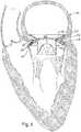
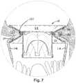
- FIGS. 6 and 7depict an example of the prosthesis 18 implanted at the mitral position in a patient's heart 110.
- FIG. 7is an enlarged view of the implanted prosthesis 18 from FIG. 6 .
- the space 102 between the inflow and outflow portions 54 and 56 of the fixation support member 14provides a receptacle for receiving therein tissue at the mitral valve annulus 112.
- the annulus 112 including portions of the patient's native valve 114can fit within the corresponding receptacle space 102 formed between the opposing surfaces of the inflow and outflow portions 54 and 56 to help hold the prosthesis 18 at the desired mitral position without requiring the use of sutures.
- one or more suturescan be applied to further affix the prosthesis.
- the spikes 34can extend outwardly from the inflow and outflow portions 54 and 56 and, in turn, grippingly engage the respective native annulus tissue at the inflow end of the mitral valve and the patient's native valve leaflets 114 at the outflow portion. Additional spikes from the inflow end of the supported valve can also help fix and anchor the prosthesis 18 at the mitral position.
- the prosthesis 18can be implanted in a low invasive procedure, which may include no cardio pulmonary bypass or may be implemented with a reduced amount of cardio pulmonary bypass relative to other mitral valve replacement procedures. Additionally, when implanted, the prosthesis 18 can be implanted without removing the patient's native mitral valve, as shown. However, the prosthesis can also be implanted if the patient's value is removed (wholly or partially).
- FIGS. 8 and 9the methods for implanting the heart valve prosthesis of the invention will be described with respect to the example embodiment of the prosthesis of FIGS. 3-5 and implanted at the mitral position as depicted with respect to FIGS. 8 and 9 . It will be appreciated that other configurations of prosthesis (including FIGS. 12-13 and other designs) can be implanted according to the methods described herein. Additionally, while the methods of FIGS. 8 and 9 are described with respect to implanting the prosthesis 18 at the mitral position, the methods can be adapted for implantation at the aortic position. Thus, the prostheses shown and described herein are applicable for implantation at any atrio-ventricular position.
- the heart valve prosthesis 18is inserted into a barrel 120 of an implanter, such that the prosthesis has the reduced cross-sectional dimension relative to the expanded cross-sectional dimension of the prosthesis.
- the implantercan be of the type shown and described with respect to FIG. 19 of U.S. Patent Application Serial No. 10/266,380 , (publication No. US 2003/0040792), filed on October 8, 2002 , and entitled HEART VALVE PROSTHESIS AND SUTURELESS IMPLANTATION OF A HEART VALVE.
- the implanter in the above patent applicationprovides a substantially linear barrel, which can have a flexible or bendable tip to facilitate direct implantation through the heart to the desired implantation site.
- This type of implanteris especially well-suited for mitral valve replacement over catheters or other percutaneous types of implanters due to the large diameter of typical native mitral valves.
- Other types of implantersmay also be employed for performing the methods described herein.
- an opening 122is created in the patient's heart 110 to provide a substantially direct path to a valve annulus 112 in the patient's heart 110.
- substantiallyas modifier for "direct path” is intended to convey that the opening is intended to provide a line-of-sight path from the opening to the implantation site, although some deviation might exist. Such deviation can be compensated, for instance, by employing a bendable barrel 120 that can be inelastically deformed to a shape to facilitate implantation at the site or by deforming the heart manually during the procedure to provide the corresponding path along which the barrel can traverse. This is to be contrasted with percutaneous implantation procedures that are performed through femoral vein, for example.
- a mattress suture, or other type of purse string suture 127can be applied at location in the patient's heart through which the implanter is to be inserted.
- the locationcomprises the patient's heart muscle located at the apex 126 of the heart 110.
- Two ends of the purse string 127 sutureextend from the apex tissue can be tightened around the barrel 120 to mitigate blood loss. Consequently, cardiopulmonary bypass is not required. However, it is to be understood that in certain situations, some bypass may be necessary, although usually for a much shorter period of time than with conventional procedures.
- the barrel 120 of the implanterhas been inserted through the apex 126 of the patient's heart 110.
- the valve of the prosthesis 18in its reduced cross-sectional dimension, can have a diameter of 15 mm to 20 mm for implanting a valve having a 24-35 mm fully expanded diameter.
- valve dimensionse.g., ⁇ 24 mm
- ⁇ 24 mmare not suitable for percutaneous implantation procedures.
- such sizes of valvesare deemed appropriate and sometimes necessary for replacement of the mitral valve.
- many existing manufactured pericardial valve designs designed for minimally invasive percutaneous implantationare not effective at such large sizes and/or are not capable of operating under the hemodynamic conditions that typically exist for the mitral position.
- the insertion of the implantercan be guided by a patient's finger (or other instrument) 128 that is introduced via the left atrial appendage 130.
- a purse string or mattress suture 132can be applied around the atrial appendage to mitigate blood loss.
- the surgeon's fingercan locate the patient's native valve and associated annulus 112 to help position and guide the distal end of the implanter to the desired implantation site.
- the valvecan be discharged from the barrel 120 of the implanter and the implanter withdrawn from the heart 110.
- the finger (or other instrument) 128can also be used help guide the valve to ensure its fixation and implantation at the appropriate position at the mitral annulus 112, such as shown in Figs. 6 and 7 .
- the valveAfter the prosthesis 18 has been expanded to its expanded cross-sectional dimension (See FIGS. 6 and 7 ), which may be performed automatically by expansion of the valve or by manual means such as the balloon catheter or other mechanism for expanding the prosthesis, the valve is fixed at the desired position.
- one or more suturescan be applied externally through the heart 110 to help anchor the prosthesis 18 at the desired implantation position.
- a trocar or other devicecan be inserted through the left atrial appendage 130 or otherwise to provide a suture or other means for further securing the prosthesis 18 at such position.
- FIG. 9depicts part of an implantation method in which the barrel 120 of the implanter and prosthesis 18 are inserted through the left atrial appendage 130 for direct implantation at the mitral annulus 112.
- the steps up to insertion of the barrel into the atrial appendage 130are similar to those described with respect to FIG. 8 .
- the chestis opened, a purse string suture 132 applied about the atrial appendage 130 and the barrel 120 is inserted through the opening through the atrial appendage.
- the purse string 132can be tightened about the barrel to mitigate blood loss, thereby allowing the absence of cardio pulmonary bypass.
- a positioning apparatuse.g., a dilator or umbrella or other structure
- a positioning apparatuse.g., a dilator or umbrella or other structure
- a purse string suture 127can be employed at the apex 126 and tightened around the instrument to control bleeding.
- the placement of the positioning apparatus 136can be guided by fluoroscopy or other imaging modalities.
- positioning apparatus 136can include an umbrella-type distal end 138 that is attached to a shaft 140.
- the distal end 138can be inserted in a closed condition through the apex 126 to a desired position the patient's heart valve and expanded to an open condition.
- the distal surface of the opened umbrella 138provides a back stop against which the discharge end of the barrel 120 or prosthesis 18 can engage for defining an implantation position. For instance, once the barrel 120 of the implanter engages the distal end 138, which can be felt or otherwise perceived by the surgeon, the prosthesis 18 can be discharged from the barrel at the mitral valve annulus.
- the inflow and outflow portions 54 and 56 of the fixation support member 14can receive tissue at the mitral annulus and thereby hold the prosthesis 18 at a fixed axial position relative to the mitral annulus 112, as shown in FIGS. 6 and 7 .
- FIG. 10demonstrates another example of support structures 150 and 12 that can be utilized to provide a heart valve prosthesis 152 (See FIGS. 12 and 13 ).
- the valve support structure 12is identical to the structure shown and described with respect to FIG. 1 . Accordingly, reference can be made back to the corresponding description in FIG. 1 for additional information about the valve support structure 12.
- the fixation support structure 150is formed of separate inflow and outflow support structures 154 and 156 that can be utilized to provide a corresponding fixation support having the appropriate dimensions and configuration for use with the prosthesis.
- each of the respective inflow and outflow support structures 154 and 156can be formed of a stent or other supporting structure (e.g., similar to the stent or support structure 12 utilized to form the supported valve 16).
- Each support structure 154 and 156can have a substantially frusto-conical configuration and a respective opening 158 and 160 that extends therethrough.
- a maximum diameter of each support structure 154 and 156is greater than the outer diameter the supported valve 16 for which it is to be utilized.
- each openingcan approximate the outer diameter the supported valve 16.
- Each support structure 154 and 156thus can have a generally sinusoidal or zigzag sidewall pattern of support features extending axially and radially outwardly from the respective opening 158 and 160 to its opposing end.
- each support structure 154 and 156can be reduced to a diameter of the opening, such as by applying a cord 162 and 164 to reduce the respective openings 158 and 160 to a desired diameter.
- the cords 162 and 164thus can be utilized to selectively provide the radially inner dimension of the inflow and outflow support structures 154 and 156 to a desired diameter for each such portion.
- the diameters of the openings 158will be substantially the same.
- Those skilled in the artwill appreciate other ways to achieve desired dimensions and configuration for each of the support structure 154 and 156, which can include structurally constructing the support structures or using other means for reducing one of the ends.
- Each of the inflow and outflow support structures 154 and 156 for the fixation support membercan include spikes 166 that extend outwardly from the distal (larger diameter) ends, such as shown in FIG. 10 .
- Various numbers and configurations of the spikes 166can be implemented, such as single spike or more than two spikes at some or all of the ends. Additionally, ends of the spikes 166 can have tapered or sharpened and/or barbed tips to facilitate gripping surrounding tissue when implanted.
- each of the fixation support structures 154, 156can be covered with a web 168,
- each web 168, 170of flexible biocompatible material to provide respective inflow and outflow fixation support portions 173 and 175.
- the materials of each web 168, 170can be the same as those mentioned in relation to the example of FIG. 2 .
- the web 168can cover and be folded over the inflow end of the inflow support structure 154, such that the seam of the fold at the inflow end defines the inflow end 172 of the covered fixation support member 174.
- the other end of the web 168can cover and be folded over respective inflow and outflow ends of the inflow support structure 154, such that its seam at the opening 158 defines a contact end 176.
- the other support structure 156can be covered by the web 170 in a similar manner, such that the web is folded over the ends to define an outflow end 178 of fixation support member and another contact end 180 thereof.
- Sutures or other meanse.g., adhesive, staples or the like
- each support structure 154, 156has been covered with webs 168 and 170 to provide respective support portions 173 and 175, such as shown in Fig. 11 , the respective contact ends 176 and 180 can be attached together and connected about the supported valve 16 to form the prosthesis 152.
- the inflow and outflow fixation support portions 173 and 175thus form the corresponding fixation support member 174, such as shown in Figs. 12 and 13 .
- the respective contact ends 176 and 180can be attached (e.g., by sutures) to the folded over portion of the web 84 at the inflow end 88 of the supported valve 16 similar to the example of FIGS. 3-5 shown and described herein. Additionally, prior to attachment to the supported valve 16, the respective inflow and outflow support portions 173 and 175 can be attached together at their contact ends 176 and 180 (e.g., anastomosis via sutures) which combined structure, defining the fixation support member 174, can then be attached at the inflow end 88 of the supported valve 16.
- the fixation support member 174 of the prosthesis 152can have a substantially V-shaped cross-sectional configuration of the 14 in its expanded cross-sectional dimension.
- the legs of the V-shaped cross sectionare formed of the opposing surfaces of the respective support structures 173 and 175.
- the space between the legs of the V-shaped cross-sectional configurationdefines a receptacle, indicated at 184.
- the receptaclethus is dimensioned and configured for receiving tissue therein.
- the angular relationship of the respective support structures 173 and 175can also be implemented as discussed with respect to the example of FIG. 5 .
- an angle between the facing surfaces of the respective inflow and outflow support portions 173 and 175can be greater than 40°, typically ranging between 70 and 100°.
- the angular contribution of the outflow portion 175can be greater than that of the inflow portion, such as described with respect to FIG. 5 , to better accommodate the dimensions and configurations of the mitral valve annulus, which may include the patient's native leaflets when the prosthesis 152 is implanted.
- the supported valve 16can be provided with a diameter or size that is greater than 23 millimeters, such as ranging from about 25 millimeters to about 34 millimeters, or even larger.
- the prosthesis 174thus can be configured to function and can be implanted as described with respect to FIGS. 8 and 9 .
Landscapes
- Health & Medical Sciences (AREA)
- Engineering & Computer Science (AREA)
- Biomedical Technology (AREA)
- Cardiology (AREA)
- Oral & Maxillofacial Surgery (AREA)
- Transplantation (AREA)
- Heart & Thoracic Surgery (AREA)
- Vascular Medicine (AREA)
- Life Sciences & Earth Sciences (AREA)
- Animal Behavior & Ethology (AREA)
- General Health & Medical Sciences (AREA)
- Public Health (AREA)
- Veterinary Medicine (AREA)
- Prostheses (AREA)
Description
- The present invention relates to a heart valve prosthesis.
- Various types of heart valve prostheses have been developed to replace the patient's native valve exhibiting valvular disease or dysfunction.
- Valve replacement offers requires open heart surgery, although more minimally invasive procedures (e.g., percutaneous implantation) may be utilized for replacing certain valves. Heart valve prostheses typically are either mechanical valve designs or biological designs. The type of heart valve prosthesis and method of implantation are often dictated according to which valve requires replacement and the size of the valve. For example, a mitral valve is often larger than 23 millimeters, making various mechanical and many types of pericardial valves inadequate for replacement. Additionally, because of the large size, in order to have a functioning and effective replacement valve, the replacement procedure cannot be done percutaneously or using a traditional catheter.
EP 2 248 486 relates to a device for occluding a hole in a body wall; among the several embodiments, it describes a heart valve prosthesis comprising a supported valve and a fixation element formed by two conical stents for a stent carrying a valve.US 2008/208327 describes a percutaneously delivered adapter stent that is deployed within a previous implanted prosthetic valve and serves as an anchor or platform for implanting a percutaneously delivered replacement valve within the previously implanted valve.WO 2010/127041 describes an apparatus for replacing a native cardiac valve. The cardiac valve has at least one leaflet and is surrounded by native cardiac valve annulus having superior and inferior aspects. The apparatus comprises a barbell-shaped expandable anchoring member.US 2006/271166 describes a stent-less support structure capable of being at least partially assembledin situ. The support structure comprises a braided tube that is very flexible and when elongated becomes very long and very small in diameter.US 2002/032481 describes a heart valve prosthesis mounted within a support apparatus that is deformable between a first condition and a second condition. The prosthesis has a cross-sectional dimension in the second position that is less than a cross-sectional dimension of the supported valve when in first condition.- The present invention relates to a heart valve prosthesis as defined by the appended claims. Methods of implanting the prosthesis, such as at the mitral or aortic position are also described.
- Herein described is a heart valve prosthesis comprising a supported valve that includes a biological valve portion mounted within a support structure. The supported valve is configured to provide for substantially unidirectional flow of blood through the supported valve. The supported valve has inflow and outflow ends that are spaced axially apart from each other. A fixation support member includes inflow and outflow portions. The inflow portion of the fixation support member extends from a radially inner contact surface of the fixation support member radially outwardly and axially in a direction of the inflow end of the supported valve. The outflow portion of the fixation support member extends from the radially inner contact surface radially outwardly and axially in a direction away from the inflow portion of the fixation support member. The radially inner contact surface is attached to a radially outer surface of the supported valve adjacent the inflow end of the supported valve. The supported valve and the fixation support member are deformable between a reduced cross-sectional dimension and an expanded cross-sectional dimension thereof, whereby implantation of the heart valve prosthesis is facilitated.
- Described are methods of implanting the prosthesis at a valve annulus (e.g., a mitral valve annulus or aortic valve annulus) during a low invasive procedure.
Fig. 1 is an exploded view depicting examples of support structures that can be utilized in a heart valve prosthesis according to an aspect of the invention.Fig. 2 is an exploded view of a heart valve prosthesis according to an aspect of the invention.Fig. 3 depicts an example of a heart valve prosthesis according to an aspect of the invention.Fig. 4 is a side elevation of the heart valve prosthesis ofFig. 3 .Fig. 5 is a cross-sectional view of the prosthesis inFig. 4 , taken along line 5-5.Fig. 6 depicts an example of a heart valve prosthesis implanted at the mitral position.Fig. 7 is an enlarged view of the implanted prosthesis ofFig. 6 demonstrating its attachment at the mitral valve annulus.Fig. 8 depicts an example of the heart valve prosthesis being implanted at the mitral position through the heart muscle according to an embodiment of the invention.Fig. 9 depicts an example of the heart valve prosthesis being implanted at the mitral position through an atrial appendage according to another embodiment of the invention.Fig. 10 depicts an example of other support structures that can be utilized for a heart valve prosthesis.Fig. 11 is an exploded view of a heart valve prosthesis using the support structures ofFig. 10 .Fig. 12 is an example of the constructed valve fromFig. 11 .Fig. 13 is a side elevation of the valve ofFig. 12 .- The invention relates generally to a heart valve prosthesis according to
claim 1 that includes a fixation support member dimensioned and configured to facilitate implantation using low invasive procedures. The prosthesis is well suited for implantation at an atrio-ventricular position. For example, the prosthesis can be made in larger sizes (e.g., greater than 24 mm) often required for mitral valve replacement. The prosthesis can also be utilized for replacement of the aortic valve. Fig. 1 depicts an example ofsupport structures support structure 10 is utilized to anchor or help hold the prosthesis in a desired axial position relative to the heart valve annulus when implanted. Thesupport structure 12 is utilized to support the valve in a desired orientation, which support can vary according to the type and configuration of heart valve implemented in the prosthesis. Thus, thesupport structure 10 is utilized to form afixation support member 14, such as shown inFig. 2 , and thesupport structure 12 can be utilized (e.g., as a stent) to support a valve portion and provide a supportedheart valve 16, as shown inFig. 2 . Accordingly, as used herein, thesupport structure 10 may be referred to as a fixation support structure and thesupport structure 12 may be referred to as a valve support, such as a stent.- The
fixation support structure 10 can be implemented as a flexible and deformable annular support that can be deformed to a reduced cross-sectional dimension and then expanded to its original, fully expanded, cross-sectional dimension, such as shown inFig. 1 . Thefixation support structure 10 includes aninflow portion 20 and anoutflow portion 22. An annular opening extends through thesupport structure 10 corresponding to a radially inner extent thereof, indicated atdashed line 28, of the support. - In the example of
FIG. 1 , each of the inflow andoutflow portions Fig. 1 , the inflow support features 24 extend radially outwardly and axially from theinner extent 28 toward in an inflow direction. Conversely, the outflow support features 26 extend from theinner extent 28 radially outwardly and axially toward an outflow direction (e.g., in the opposite axial direction from the inflow support features). Each of theinflow support features 24 extends from the radiallyinner extent 28 and terminates into a correspondingdistal end 30 thereof. Similarly, each of theoutflow support features 26 also extends from the radiallyinner extent 28 to terminate in a respectivedistal end 32. Thus, each pair of adjacent support features 24 extend toward each other and are interconnected at a juncture corresponding to thedistal end 30, whilesupport features 26 can be formed of a pair of adjacent supports that extend toward each other and are connected at a juncture corresponding to thedistal end 32. The respective junctures can be biased (e.g., configured as springs) to urge each of the associated legs apart to maintain thesupport structure 10 in its expanded condition. In the example ofFig. 1 , there are eight junctures at each of therespective ends - As a further example, the
fixation support structure 10 can be configured as a continuous monolithic structure, such as shown inFIG. 1 . Thus, the support features 24 and 26 alternate between extending in the inflow and outflow directions along the circumferential path corresponding to the radiallyinner extent 28 of thesupport structure 10. By way of example, thefixation support structure 10 can be formed from a stent similar to the valve support structure 12 (having a zigzag arrangement of support features) in which the distal ends 30 and 32 are bent radially outwardly while a substantially central annular portion is maintained at the original diameter. Alternatively, an axially central annular portion of a larger diameter cylindrical support (having the zigzagging support features) can be reduced to a desired inner diameter of the radially inner extent, such as by a suture or other means. Other types and configurations of supports can also be utilized (see, e.g.,Figs. 10-13 ). Due to the structural arrangement of support features 24 and 26 that define the respective inflow andoutflow portions fixation support structure 10, it is thus shown that the fixation support provides a generally hourglass shape in which it has a substantially V-shaped cross-sectional configuration for a longitudinal cross-section taken radially outwardly through one side of the fixation support in its expanded configuration ofFig. 1 . - The inflow and
outflow portions spikes 34 can extend from the distal ends 30, 32 of the support features 24 and 26 toward an opposing one of the outflow orinflow portion support structure 10. For instance, spikes from theinflow portion 20 extend from thedistal end portion 30 axially away from thesupport feature 24 toward theopposing outflow portion 26. Similarly, spikes from theoutflow portion 22 extend from thedistal end portion 32 axially away from thesupport feature 26 toward the opposinginflow portion 20. Various numbers and arrangements ofspikes 34 can be implemented, such as single spike or more than two spikes at some or all of theends spikes 34 can have tapered or sharpened and/or barbed tips to facilitate gripping surrounding tissue when implanted. - As depicted in
Fig. 2 , thefixation support member 14 can include one ormore web 38 of flexible biocompatible material that is attached over and covers the respective inflow andoutflow portions web 38 can include aninflow web portion 40 that covers an inflow extent of the support features 24, as well as anoutflow web portion 42 that covers the outflow support features 26. For example, theinflow web portion 40 of thefixation support member 14 can extend from a radially inner contact surface 44 (e.g., corresponding to the radiallyinner extent 28 ofFIG. 1 ) and extend over and engage the support features 24 to terminate at an inflowdistal end 46 of thesupport member 14. Thus, the surface of the support features 24, as exposed in an inwardly axial direction, is completely covered. Thedistal end 46 can be defined by a seam as the end of theinflow web 40 is folded over thedistal end portions 30 of the support features 24. The folded over ends can be attached together by correspondingsutures 48. - The
outflow web 42 can be similarly configured as extending from the radiallyinner contact surface 44 to define adistal outflow edge 50 of the outflow portion of thefixation support member 14. Theedge 50 can be defined by folding the end of the web over thedistal end portions 32 of the outflow support features 26 and attaching the ends together by correspondingsutures 52. For example, the folded over portion of the inflow andoutflow webs respective spikes 34 to be exposed and facilitate their insertion and gripping tissue when the resulting prosthesis is implanted. - The
inflow web 40 covering theinflow portion 20 of thefixation support structure 10 thus corresponds to aninflow portion 54 of the completedfixation support member 14. Similarly, theoutflow web 42 covering theoutflow portion 22 of thefixation support structure 10 thus corresponds to anoutflow portion 56 of thefixation support member 14. It is to be understood that therespective webs web 38. Referring back toFIG. 1 , thevalve support structure 12 includes axially spaced apart ends 60 and 62 interconnected by generally axially extending support features 64. In the example ofFig. 1 , adjacent pairs of support features 64 are interconnected byarcuate junctures 66 and 68 at the respective ends 60 and 62 so as to define a generally sinusoidal or zigzag shapedsidewall portion 70 arranged in a generally cylindrical configuration. In the example ofFig. 1 , there are sixjunctures 66 and 68 at each of the respective ends 60 and 62 that are interconnected by associated support features 64. Those skilled in the art will understand and appreciate that other numbers (e.g., 2, 5, 8, 12 and so forth) and configurations ofend junctures 66, 68 can be utilized in accordance with an aspect of the present invention. For example, as an alternative to curved interconnectingend junctures 66, 68 shown inFig. 1 , such ends could be pointed or rectangular or be implemented as coil springs. - The
support structure 12 further includes one or more projections or spikes 72 that extend axially and radially outwardly from the end juncture 66, corresponding to the inflow end of the support. While a pair of such spikes are illustrated as associated with eachend juncture 66, 68, other number of spikes can be implemented, such as single spike or more than two spikes at some or all of the junctures. Thespikes 72 operate to mitigate axial movement of the prosthesis when implanted, such as by having each spike 72 forming an acute angle relative to its associated support feature 64 from which it extends. - By way of further example, one or both of the
support structures support structures Fig. 3 ) may be cooled, such as by being introduced to a cooling solution (e.g., water), and then compressed to a desired reduced cross-sectional dimension to facilitate insertion into an implanter. Typically when compressed the inflow and outflow portions will be urged radially inwardly to a diameter that is less than an outer diameter of the supported valve in its expanded condition. - When the
prosthesis 18, which includessupport structures prosthesis 18 will then return toward its high-temperature (or original) position upon removal of the retaining element. - It is to be appreciated that, alternatively, the
support structures support structures valve 76 located therein generally radially outward so that, after being implanted to a desired
position, the stent will engage the surrounding tissue in a manner to inhibit movement relative to the surrounding tissue. - Returning to
FIG. 2 , the supportedvalve 16 includes aheart valve 76 mounted within thevalve support structure 12. Thevalve 76 includes aninflow end 78 and anoutflow end 80 at axially opposed ends of the valve, with a sidewall portion extending between the ends thereof. Theinflow end 78 of thevalve 76 is positioned near aninflow end 60 of thesupport structure 12. A plurality ofleaflets 82 extend radially inward from the valve wall and coapt along their adjacent edges to provide for substantially unidirectional flow of blood through thevalve 76. Theoutflow end 80 of thevalve 76, which is located near theoutflow end 62 of the support, can have a generally sinusoidal contour, such as shown inFig. 2 . The peaks of the sinusoidal outflow end (corresponding to commissures of leaflets) can be aligned generally with and attached to support junctures 66 at theinflow end 62 of thesupport structure 12. Thevalve 76 can be connected within thesupport structure 12 via sutures or other known connecting means, for example. - It is to be understood and appreciated that various types of valve configurations of could be utilized for the supported
valve 16. For example, thevalve 76 can be formed of biological material and include one or more leaflets mounted within a length of tubular valve wall or other generally cylindrical biocompatible material and operate in a known manner to provide for the unidirectional flow of fluid through the valve from the inflow to outflow ends. As one example, when the prosthesis is to be implanted at the mitral position, thevalve 76 can be a treated porcine mitral valve (e.g., homograft or xenograft). While porcine valves have been recognized by the inventor as being effective, those skilled will understand that other animal heart valve can be utilized, such as bovine, equine or the like. - If the
valve portion 76 is formed of a natural biological material, such as an animal heart valve, a venous valve, or a composite valve manufactured of natural tissue, the valve can be chemically fixed, such as in a suitable solution of glutaraldehyde in a closed condition (as is known in the art). The fixation process facilitates closure of thevalve 76 under application of back flow pressure, while remaining open during normal forward blood flow through thevalve 76. By way of example, the natural tissue valve may be cross-linked with glutaraldehyde and undergo a detoxification process with heparin bonding, as to improve biocompatibility of thevalve 76 and mitigate calcification and thrombus formation. - As a result of such fixation, the
valve portion 76 exhibits structural memory. That is, if thevalve 76 is compressed, such as to a reduced diameter at the time of being implanted, it will return substantially to its original shape and configuration upon removal of radially inward forces. As a result, thevalve 76 is able to maintain coaptation of theleaflets 82 even after being deformed. The memory feature of the valve is further augmented by mounting it within the valve support structure (or stent) 12, such as shown and described herein. - In the example of
FIG. 2 , the ends 60 and 62 of thevalve support structure 12 are covered with one ormore sheet 84 of a pliant and biocompatible material that provides an outer sheath for the supportedvalve 16. The outer sheath mitigates contact between the blood and the support when the prosthesis is implanted. The biocompatible material can be a nature material (e.g., animal pericardium, dura matter) or a synthetic material (e.g., synthetic pericardium substitute, such as a bioabsorbable polymer). The outer sheath can be the same material as theweb 38 for thefixation support member 14 or it can be a different material. - For instance, the
sheet 84 can be attached to a radial outer surface of thevalve 76 and placed over the inflow and outflow ends 60 and 62 by folding the material over the ends of the support features 64. The folded over ends can be attached together by correspondingsutures 86 applied at each of the respective inflow and outflow ends of the supportedvalve 16. The seam of the folds at each of the respective ends can thus define theinflow end 86 and theoutflow end 88 of the supportedvalve 16. Alternatively, the outer sheath can cover the entire outer surface ofsupport structure 12, such that all non-biological material is completely covered, for example. Figs. 3 ,4 and 5 depict aheart valve prosthesis 18 constructed from thefixation support member 14 and the supportedvalve 16 shown and described with respect toFig. 2 . Accordingly, the same reference numbers are utilized to identify features already introduced. As described herein, theprosthesis 18 is deformable between a reduced cross-sectional dimension and an expanded cross-sectional dimension thereof, such that implantation of the heart valve prosthesis is facilitated.- The
fixation support member 14, including the inflow andoutflow portions valve 16 adjacent aninflow end 88 of the supported valve. As best shown inFigs. 3 and5 , the radiallyinner contact surface 44 of thefixation support member 14 is attached to a radially outer sidewall surface of the supportedvalve 16 adjacent the inflow end thereof. The attachment can be made by sutures, or other means of attachment such as surgical adhesives, staples. For example, the radiallyinner contact surface 44 can be secured to the folded overouter sheath 84 at the inflow end. Alternatively, the radiallyinner contact surface 44 can engage the sidewall just below the edge of theouter sheath 84 so that the folded over outer sheath, having two layers provides addition structure for suturing the fixation support member to the supportedvalve 16. - As shown in the example of
FIGS. 4 and 5 , sutures 94 can be applied to attach the radiallyinner contact surface 44 at the inflow end of the supportedvalve 16. The arrangement ofsutures 94 can be applied externally to help hold and maintain the desired axial position of thefixation support member 14 relative to the supportedvalve 16.Additional sutures 96 can be applied to further secure the inflow end of the supportedvalve 16 to the adjacent portion of theinflow web 40, along the entire perimeter thereof, such as shown inFigs. 3 and5 . - Additionally, to help maintain a desired diameter of the radially
inner contact surface 44 of thefixation support member 14, a cord (e.g., a suture or other retaining mechanism) 100 can be applied externally at the juncture of the inflow andoutflow portions cord 100 can be applied around thesupport structure 10 before or after the web covering 38 is attached. Alternatively, or additionally, the dimensions of the radiallyinner contact surface 44 can be set by structural or material properties utilized to form thesupport structure 10, such that nocord 100 is required. - In the cross-sectional view of
Fig. 5 , it is shown that a longitudinal cross-section through theprosthesis 18 demonstrates a substantially V-shaped cross-sectional configuration of thefixation support member 14 in its expanded cross-sectional dimension. For instance, the radiallyinner contact surface 44
defines an apex and each of the inflow and outflow portions of the fixation support member define legs of the V-shaped cross-sectional configuration. It will be appreciated that the term "substantially" as used in relation to the V-shaped configuration is intended to encompass that the apex of the "V" can be curved or arcuate (as shown inFIG. 5 ) as well as being pointed. Additionally, the legs of the V-shaped configuration do not need to perfectly straight, but can be curved provided that distal ends of the inflow and outflow portions are axially spaced apart to enable tissue to be received therebetween when implanted. The space between the legs of the V-shaped cross-sectional configuration defines a receptacle, indicated at 102, dimensioned and configured for receiving tissue therein. For the example ofFIGS. 2-5 , thereceptacle 102 has a generally toroidal shape. It will be understood that thefixation support member 14 may be implemented with or without the web or other covering or with a different covering that is not continuous, as in the examples ofFIGS. 3-5 . - As also depicted in the example of
FIG. 5 , theinflow portion 54 is separated from theoutflow portion 56 in its expanded condition by an angle equal to the sum of angles θ1 and θ2, each of which is drawn relative to aplane 104 that extends through theprosthesis 18 transverse to the longitudinal axis thereof. The combined angle of θ1 + θ2 is greater than 40°, and typically ranges between 70 and 100°. Additionally, θ2 can be greater than θ1 to better accommodate receiving native tissue for implantation of theprosthesis 18 at the mitral position. - Since according to one embodiment the
prosthesis 18 can be implanted at the mitral position, the supportedvalve 16 can be provided with a diameter or size that is greater than 23 millimeters, such as ranging from about 25 millimeters to about 34 millimeters, or even larger. Also depicted inFig. 5 , in its expanded condition, therespective spikes 34 offixation support member 14 extend outwardly from the inflow andoutflow portions space 102 toward the opposite outflow and inflow portions to facilitate insertion and fixation of the fixation support member in tissue when implanted. FIGS. 6 and7 depict an example of theprosthesis 18 implanted at the mitral position in a patient'sheart 110.FIG. 7 is an enlarged view of the implantedprosthesis 18 fromFIG. 6 . As shown inFIGS. 6 and7 , thespace 102 between the inflow andoutflow portions member 14 provides a receptacle for receiving therein tissue at themitral valve annulus 112. Thus, theannulus 112, including portions of the patient'snative valve 114, can fit within the correspondingreceptacle space 102 formed between the opposing surfaces of the inflow andoutflow portions prosthesis 18 at the desired mitral position without requiring the use of sutures. Of course, one or more sutures (not shown) can be applied to further affix the prosthesis.- Also demonstrated in
FIGS. 6 and7 , thespikes 34 can extend outwardly from the inflow andoutflow portions native valve leaflets 114 at the outflow portion. Additional spikes from the inflow end of the supported valve can also help fix and anchor theprosthesis 18 at the mitral position. - As described herein, the
prosthesis 18 can be implanted in a low invasive procedure, which may include no cardio pulmonary bypass or may be implemented with a reduced amount of cardio pulmonary bypass relative to other mitral valve replacement procedures. Additionally, when implanted, theprosthesis 18 can be implanted without removing the patient's native mitral valve, as shown. However, the prosthesis can also be implanted if the patient's value is removed (wholly or partially). - For consistency of explanation, the methods for implanting the heart valve prosthesis of the invention will be described with respect to the example embodiment of the prosthesis of
FIGS. 3-5 and implanted at the mitral position as depicted with respect toFIGS. 8 and 9 . It will be appreciated that other configurations of prosthesis (includingFIGS. 12-13 and other designs) can be implanted according to the methods described herein. Additionally, while the methods ofFIGS. 8 and 9 are described with respect to implanting theprosthesis 18 at the mitral position, the methods can be adapted for implantation at the aortic position. Thus, the prostheses shown and described herein are applicable for implantation at any atrio-ventricular position. - At some time prior to implanting the valve at the desired implantation site, for each of the approaches of
FIGS. 8 or 9 , theheart valve prosthesis 18 is inserted into abarrel 120 of an implanter, such that the
prosthesis has the reduced cross-sectional dimension relative to the expanded cross-sectional dimension of the prosthesis. The implanter can be of the type shown and described with respect to FIG. 19 ofU.S. Patent Application Serial No. 10/266,380 , (publication No.US 2003/0040792), filed on October 8, 2002 , and entitled HEART VALVE PROSTHESIS AND SUTURELESS IMPLANTATION OF A HEART VALVE. The implanter in the above patent application provides a substantially linear barrel, which can have a flexible or bendable tip to facilitate direct implantation through the heart to the desired implantation site. This type of implanter is especially well-suited for mitral valve replacement over catheters or other percutaneous types of implanters due to the large diameter of typical native mitral valves. Other types of implanters may also be employed for performing the methods described herein. - Returning to the example of
FIG. 8 , before inserting thebarrel 120 into the patient'sheart 110, an opening 122 is created in the patient'sheart 110 to provide a substantially direct path to avalve annulus 112 in the patient'sheart 110. As used herein, the term "substantially" as modifier for "direct path" is intended to convey that the opening is intended to provide a line-of-sight path from the opening to the implantation site, although some deviation might exist. Such deviation can be compensated, for instance, by employing abendable barrel 120 that can be inelastically deformed to a shape to facilitate implantation at the site or by deforming the heart manually during the procedure to provide the corresponding path along which the barrel can traverse. This is to be contrasted with percutaneous implantation procedures that are performed through femoral vein, for example. - As a further example, a mattress suture, or other type of
purse string suture 127 can be applied at location in the patient's heart through which the implanter is to be inserted. In the example ofFIG. 8 , the location comprises the patient's heart muscle located at the apex 126 of theheart 110. Two ends of thepurse string 127 suture extend from the apex tissue can be tightened around thebarrel 120 to mitigate blood loss. Consequently, cardiopulmonary bypass is not required. However, it is to be understood that in certain situations, some bypass may be necessary, although usually for a much shorter period of time than with conventional procedures. - As shown in
FIG. 8 , thebarrel 120 of the implanter has been inserted through the apex 126 of the patient'sheart 110. For instance, the valve of theprosthesis 18, in its reduced cross-sectional dimension, can have a diameter of 15 mm to 20 mm for implanting a valve having a 24-35 mm fully expanded diameter. Those skilled in the art will appreciate that valve dimensions (e.g., ≥ 24 mm) are not suitable for percutaneous implantation procedures. However, such sizes of valves are deemed appropriate and sometimes necessary for replacement of the mitral valve. Additionally, many existing manufactured pericardial valve designs designed for minimally invasive percutaneous implantation are not effective at such large sizes and/or are not capable of operating under the hemodynamic conditions that typically exist for the mitral position. - During a closed heart procedure, the insertion of the implanter can be guided by a patient's finger (or other instrument) 128 that is introduced via the left
atrial appendage 130. A purse string ormattress suture 132 can be applied around the atrial appendage to mitigate blood loss. The surgeon's finger can locate the patient's native valve and associatedannulus 112 to help position and guide the distal end of the implanter to the desired implantation site. Once at the desired site, the valve can be discharged from thebarrel 120 of the implanter and the implanter withdrawn from theheart 110. The finger (or other instrument) 128 can also be used help guide the valve to ensure its fixation and implantation at the appropriate position at themitral annulus 112, such as shown inFigs. 6 and7 . - After the
prosthesis 18 has been expanded to its expanded cross-sectional dimension (SeeFIGS. 6 and7 ), which may be performed automatically by expansion of the valve or by manual means such as the balloon catheter or other mechanism for expanding the prosthesis, the valve is fixed at the desired position. As described herein, one or more sutures can be applied externally through theheart 110 to help anchor theprosthesis 18 at the desired implantation position. Alternatively, a trocar or other device can be inserted through the leftatrial appendage 130 or otherwise to provide a suture or other means for further securing theprosthesis 18 at such position. FIG. 9 depicts part of an implantation method in which thebarrel 120 of the implanter andprosthesis 18 are inserted through the left atrialappendage 130 for direct implantation at themitral annulus 112. The steps up to insertion of the barrel into theatrial appendage 130 are similar to those described with respect toFIG. 8 . Briefly, the chest is opened, apurse string suture 132 applied about theatrial appendage 130 and thebarrel 120 is inserted through the opening through the atrial appendage. Thepurse string 132 can be tightened about the barrel to mitigate blood loss, thereby allowing the absence of cardio pulmonary bypass.- In order to facilitate proper positioning of the
prosthesis 18, a positioning apparatus (e.g., a dilator or umbrella or other structure) 136 can be inserted through the heart muscle, such as theapex 126 of the patient'sheart 110, and positioned to a desired location. Apurse string suture 127 can be employed at the apex 126 and tightened around the instrument to control bleeding. The placement of thepositioning apparatus 136 can be guided by fluoroscopy or other imaging modalities. - By way of example,
positioning apparatus 136 can include an umbrella-type distal end 138 that is attached to ashaft 140. The distal end 138 can be inserted in a closed condition through the apex 126 to a desired position the patient's heart valve and expanded to an open condition. In the open condition, the distal surface of the opened umbrella 138 provides a back stop against which the discharge end of thebarrel 120 orprosthesis 18 can engage for defining an implantation position. For instance, once thebarrel 120 of the implanter engages the distal end 138, which can be felt or otherwise perceived by the surgeon, theprosthesis 18 can be discharged from the barrel at the mitral valve annulus. When expanded, the inflow andoutflow portions fixation support member 14 can receive tissue at the mitral annulus and thereby hold theprosthesis 18 at a fixed axial position relative to themitral annulus 112, as shown inFIGS. 6 and7 . Fig. 10 demonstrates another example ofsupport structures FIGS. 12 and13 ). In the example ofFIG. 10 thevalve support structure 12 is identical to the structure shown and described with respect toFIG. 1 . Accordingly, reference can be made back to the corresponding description inFIG. 1 for additional information about thevalve support structure 12.- In the example of
FIG. 10 , thefixation support structure 150 is formed of separate inflow and outflow support structures 154 and 156 that can be utilized to provide a corresponding fixation support having the appropriate dimensions and configuration for use with the prosthesis. As an example, each of the respective inflow and outflow support structures 154 and 156 can be formed of a stent or other supporting structure (e.g., similar to the stent orsupport structure 12 utilized to form the supported valve 16). Each support structure 154 and 156 can have a substantially frusto-conical configuration and arespective opening valve 16 for which it is to be utilized. The diameter of each opening can approximate the outer diameter the supportedvalve 16. Each support structure 154 and 156 thus can have a generally sinusoidal or zigzag sidewall pattern of support features extending axially and radially outwardly from therespective opening - For example, one end of each support structure 154 and 156 can be reduced to a diameter of the opening, such as by applying a
cord respective openings cords openings 158 will be substantially the same. Those skilled in the art will appreciate other ways to achieve desired dimensions and configuration for each of the support structure 154 and 156, which can include structurally constructing the support structures or using other means for reducing one of the ends. - Each of the inflow and outflow support structures 154 and 156 for the fixation support member can include
spikes 166 that extend outwardly from the distal (larger diameter) ends, such as shown inFIG. 10 . Various numbers and configurations of thespikes 166 can be implemented, such as single spike or more than two spikes at some or all of the ends. Additionally, ends of thespikes 166 can have tapered or sharpened and/or barbed tips to facilitate gripping surrounding tissue when implanted. - Referring to
FIG. 11 , corresponding inflow and outflow surfaces of each of the fixation support structures 154, 156 can be covered with aweb 168, - 170 of flexible biocompatible material to provide respective inflow and outflow
fixation support portions web FIG. 2 . For example, theweb 168 can cover and be folded over the inflow end of the inflow support structure 154, such that the seam of the fold at the inflow end defines theinflow end 172 of the coveredfixation support member 174. Similarly, the other end of theweb 168 can cover and be folded over respective inflow and outflow ends of the inflow support structure 154, such that its seam at theopening 158 defines acontact end 176. The other support structure 156 can be covered by theweb 170 in a similar manner, such that the web is folded over the ends to define anoutflow end 178 of fixation support member and anothercontact end 180 thereof. Sutures or other means (e.g., adhesive, staples or the like) can be utilized for attaching thewebs - After each support structure 154, 156 has been covered with
webs respective support portions Fig. 11 , the respective contact ends 176 and 180 can be attached together and connected about the supportedvalve 16 to form theprosthesis 152. The inflow and outflowfixation support portions fixation support member 174, such as shown inFigs. 12 and13 . - By way of example, the respective contact ends 176 and 180 can be attached (e.g., by sutures) to the folded over portion of the
web 84 at theinflow end 88 of the supportedvalve 16 similar to the example ofFIGS. 3-5 shown and described herein. Additionally, prior to attachment to the supportedvalve 16, the respective inflow andoutflow support portions fixation support member 174, can then be attached at theinflow end 88 of the supportedvalve 16. - The
fixation support member 174 of theprosthesis 152 can have a substantially V-shaped cross-sectional configuration of the 14 in its expanded cross-sectional dimension. In this example, however, the legs of the V-shaped cross section are formed of the opposing surfaces of therespective support structures - The angular relationship of the
respective support structures FIG. 5 . For instance, an angle between the facing surfaces of the respective inflow andoutflow support portions outflow portion 175 can be greater than that of the inflow portion, such as described with respect toFIG. 5 , to better accommodate the dimensions and configurations of the mitral valve annulus, which may include the patient's native leaflets when theprosthesis 152 is implanted. Since according to one embodiment theprosthesis 152 can be implanted at the mitral position, the supportedvalve 16 can be provided with a diameter or size that is greater than 23 millimeters, such as ranging from about 25 millimeters to about 34 millimeters, or even larger. Theprosthesis 174 thus can be configured to function and can be implanted as described with respect toFIGS. 8 and 9 . - What has been described above includes examples of the present invention. It is, of course, not possible to describe every conceivable combination of components or methodologies for purposes of describing the present invention, but one of ordinary skill in the art will recognize that many further combinations and permutations of the present invention are possible. Accordingly, the present invention is intended to embrace all such alterations, modifications and variations that fall within the scope of the appended claims.
Claims (11)
- A heart valve prosthesis comprising:a supported valve (16) comprising a biological valve portion (76) mounted within a support structure (12), the supported valve being configured to provide for substantially unidirectional flow of blood through the supported valve, the supported valve having inflow (78) and outflow (80) ends that are spaced axially apart from each other; anda fixation support member (14, 174) comprising inflow (40, 173) and outflow (42, 175) portions, the inflow portion of the fixation support member extending from a radially inner contact surface (44, 176, 180) of the fixation support member radially outwardly and axially in a direction of the inflow end of the supported valve, the outflow portion of the fixation support member extending from the radially inner contact surface radially outwardly and axially in a direction away from the inflow portion of the fixation support member, the radially inner contact surface being attached to a radially outer surface of the supported valve adjacent the inflow end of the supported valve, the supported valve and the fixation support member being deformable between a reduced cross-sectional dimension and an expanded cross-sectional dimension thereof, whereby implantation of the heart valve prosthesis is facilitated,wherein the fixation support member further comprises a flexible and deformable annular support (10) which includes an inflow portion (20), an outflow portion (22), and an annular opening extending through the support (10) corresponding to a radially inner extent (28) thereof, the fixation support member having a substantially V-shaped cross-sectional configuration for a longitudinal cross-section taken axially through the prosthesis in its expanded cross-sectional dimension, such that the radially inner contact surface of the fixation support member defines an apex and each of the inflow and outflow portions of the fixation support member define legs of the V-shaped cross-sectional configuration,characterised in that the annular support (10) is a continuous monolithic structure having a substantially V-shaped cross-sectional configuration for a longitudinal cross-section taken axially through the prosthesis in its expanded cross-sectional dimension, said structure consisting in a zigzag arrangement of support features (24, 26), in which the support features alternate between extending in the inflow and outflow directions along a circumferential path corresponding to the radially inner extent (28) of the support structure.
- The prosthesis of claim 1, wherein the fixation support member (14) further comprises:at least one web (38) of flexible biocompatible material covering at least an inflow surface of the support features (24) for the inflow portion (40) and at least an outflow surface of the support features (26) for the outflow portion (42), and wherein the support features are biasing each of the inflow and outflow portions of the fixation support member toward the expanded cross-sectional dimension.
- The prosthesis of claim 2, wherein at least some of the support features further comprise spikes (34) that extend outwardly from respective support features toward the other of inflow or outflow portion of the fixation support member.
- The prosthesis of claim 2, wherein the support structure (12) of the supported valve (16) further comprises a substantially cylindrical support extending between the axially spaced apart inflow and outflow ends (60, 62) thereof, the cylindrical support including a plurality of support features (64) extending generally axially between the axially spaced apart inflow and outflow ends of the cylindrical support, adjacent pairs of the support features (64) being interconnected so as to bias the cylindrical support radially outwardly toward the expanded cross-sectional dimension.
- The prosthesis of claim 1, wherein a longitudinal cross-section axially through the prosthesis in its expanded cross-sectional dimension provides an angle (Θ1, Θ2) between the inflow (54) and outflow (56) portions of the fixation support member that is greater than about forty degrees, and a space between axially opposed surfaces of the inflow and outflow portions defines a receptacle dimensioned and configured for receiving therein tissue at a valve annulus.
- The prosthesis of claim 5, wherein the angle between the inflow and outflow portions of the fixation support member ranges between approximately 70 and approximately 100 degrees.
- The prosthesis of claim 5, wherein an angle of the inflow portion of the fixation support member relative to a plane extending transversely through the prosthesis at the radially inner contact surface of the fixation support member is less than an angle of the outflow portion of the fixation support member relative to the plane.
- The prosthesis of claim 1, wherein the space between the legs of the V-shaped cross-sectional configuration of the fixation support member defines a generally toroidal receptacle (102) channel dimensioned and configured for receiving a valve annulus.
- The prosthesis of claim 1, wherein the supported valve has an expanded cross-sectional dimension that is greater than 24 mm, the inflow and outflow portions of the fixation support member (14) extending outwardly beyond the expanded cross-sectional dimension of the supported valve to provide an annular receptacle (102) between the inflow and outflow portions of the fixation support member dimensioned and configured for receiving a tissue at a valve annulus.
- The prosthesis of claim 1, wherein a valve portion of the supported valve comprises an animal tissue heart valve.
- The prosthesis of claim 10, wherein the animal tissue valve comprises a porcine valve.
Priority Applications (1)
| Application Number | Priority Date | Filing Date | Title |
|---|---|---|---|
| EP11153114.1AEP2484309B1 (en) | 2011-02-02 | 2011-02-02 | Heart valve prosthesis |
Applications Claiming Priority (1)
| Application Number | Priority Date | Filing Date | Title |
|---|---|---|---|
| EP11153114.1AEP2484309B1 (en) | 2011-02-02 | 2011-02-02 | Heart valve prosthesis |
Publications (2)
| Publication Number | Publication Date |
|---|---|
| EP2484309A1 EP2484309A1 (en) | 2012-08-08 |
| EP2484309B1true EP2484309B1 (en) | 2019-04-10 |
Family
ID=44275694
Family Applications (1)
| Application Number | Title | Priority Date | Filing Date |
|---|---|---|---|
| EP11153114.1ARevokedEP2484309B1 (en) | 2011-02-02 | 2011-02-02 | Heart valve prosthesis |
Country Status (1)
| Country | Link |
|---|---|
| EP (1) | EP2484309B1 (en) |
Cited By (15)
| Publication number | Priority date | Publication date | Assignee | Title |
|---|---|---|---|---|
| US10856984B2 (en) | 2017-08-25 | 2020-12-08 | Neovasc Tiara Inc. | Sequentially deployed transcatheter mitral valve prosthesis |
| US10940001B2 (en) | 2012-05-30 | 2021-03-09 | Neovasc Tiara Inc. | Methods and apparatus for loading a prosthesis onto a delivery system |
| US11311376B2 (en) | 2019-06-20 | 2022-04-26 | Neovase Tiara Inc. | Low profile prosthetic mitral valve |
| US11357622B2 (en) | 2016-01-29 | 2022-06-14 | Neovase Tiara Inc. | Prosthetic valve for avoiding obstruction of outflow |
| US11389291B2 (en) | 2013-04-04 | 2022-07-19 | Neovase Tiara Inc. | Methods and apparatus for delivering a prosthetic valve to a beating heart |
| US11413139B2 (en) | 2011-11-23 | 2022-08-16 | Neovasc Tiara Inc. | Sequentially deployed transcatheter mitral valve prosthesis |
| US11419720B2 (en) | 2010-05-05 | 2022-08-23 | Neovasc Tiara Inc. | Transcatheter mitral valve prosthesis |
| US11464631B2 (en) | 2016-11-21 | 2022-10-11 | Neovasc Tiara Inc. | Methods and systems for rapid retraction of a transcatheter heart valve delivery system |
| US11491006B2 (en) | 2019-04-10 | 2022-11-08 | Neovasc Tiara Inc. | Prosthetic valve with natural blood flow |
| US11497602B2 (en) | 2012-02-14 | 2022-11-15 | Neovasc Tiara Inc. | Methods and apparatus for engaging a valve prosthesis with tissue |
| US11602429B2 (en) | 2019-04-01 | 2023-03-14 | Neovasc Tiara Inc. | Controllably deployable prosthetic valve |
| US11737872B2 (en) | 2018-11-08 | 2023-08-29 | Neovasc Tiara Inc. | Ventricular deployment of a transcatheter mitral valve prosthesis |
| US11779742B2 (en) | 2019-05-20 | 2023-10-10 | Neovasc Tiara Inc. | Introducer with hemostasis mechanism |
| US11998447B2 (en) | 2019-03-08 | 2024-06-04 | Neovasc Tiara Inc. | Retrievable prosthesis delivery system |
| US12109111B2 (en) | 2015-12-15 | 2024-10-08 | Neovasc Tiara Inc. | Transseptal delivery system |
Families Citing this family (7)
| Publication number | Priority date | Publication date | Assignee | Title |
|---|---|---|---|---|
| EP2484309B1 (en) | 2011-02-02 | 2019-04-10 | Shlomo Gabbay | Heart valve prosthesis |
| WO2014022124A1 (en)* | 2012-07-28 | 2014-02-06 | Tendyne Holdings, Inc. | Improved multi-component designs for heart valve retrieval device, sealing structures and stent assembly |
| US9119713B2 (en)* | 2013-03-11 | 2015-09-01 | St. Jude Medical, Cardiology Division, Inc. | Transcatheter valve replacement |
| US20160030169A1 (en)* | 2013-03-13 | 2016-02-04 | Aortic Innovations, Llc | Dual frame stent and valve devices and implantation |
| EP2896387A1 (en) | 2014-01-20 | 2015-07-22 | Mitricares | Heart valve anchoring device |
| BR102014006114B1 (en)* | 2014-03-14 | 2022-05-10 | Antônio Francisco Neves Filho | Mechanical or biological heart valve stent for minimally invasive valve replacement procedure and stent delivery device |
| FR3058631B1 (en)* | 2016-11-14 | 2019-01-25 | Laboratoires Invalv | IMPLANT FOR TREATING A BIOLOGICAL VALVE |
Citations (24)
| Publication number | Priority date | Publication date | Assignee | Title |
|---|---|---|---|---|
| US6425916B1 (en) | 1999-02-10 | 2002-07-30 | Michi E. Garrison | Methods and devices for implanting cardiac valves |
| US20040147868A1 (en) | 2003-01-27 | 2004-07-29 | Earl Bardsley | Myocardial implant with collar |
| US20040210304A1 (en) | 1999-11-17 | 2004-10-21 | Corevalve, S.A. | Prosthetic valve for transluminal delivery |
| US20050137687A1 (en) | 2003-12-23 | 2005-06-23 | Sadra Medical | Heart valve anchor and method |
| US20060149360A1 (en) | 2003-07-08 | 2006-07-06 | Ventor Technologies Ltd. | Fluid flow prosthetic device |
| WO2006127756A2 (en) | 2005-05-24 | 2006-11-30 | Edwards Lifesciences Corporation | Rapid deployment prosthetic heart valve |
| US20060276813A1 (en) | 2005-05-20 | 2006-12-07 | The Cleveland Clinic Foundation | Apparatus and methods for repairing the function of a diseased valve and method for making same |
| WO2007072469A2 (en) | 2005-12-23 | 2007-06-28 | Vysera Biomedical Limited | A medical device suitable for treating reflux from a stomach to an oesophagus |
| WO2007071436A2 (en) | 2005-12-22 | 2007-06-28 | Symetis Sa | Stent-valves for valve replacement and associated methods and systems for surgery |
| US20070213813A1 (en) | 2005-12-22 | 2007-09-13 | Symetis Sa | Stent-valves for valve replacement and associated methods and systems for surgery |
| WO2008106531A1 (en) | 2007-02-27 | 2008-09-04 | Edwards Lifesciences Corporation | Method and apparatus for replacing a prosthetic valve |
| US20080300678A1 (en) | 2007-02-05 | 2008-12-04 | Eidenschink Tracee E J | Percutaneous valve, system and method |
| WO2009024859A2 (en) | 2007-08-21 | 2009-02-26 | Symetis Sa | Stent-valves for valve replacement and associated methods and systems for surgery |
| WO2009045338A1 (en) | 2007-09-28 | 2009-04-09 | St. Jude Medical, Inc. | Collapsible-expandable prosthetic heart valves with structures for clamping native tissue |
| WO2009053497A1 (en) | 2007-10-25 | 2009-04-30 | Symetis Sa | Stents, valved-stents and methods and systems for delivery thereof |
| US7534261B2 (en) | 2006-10-02 | 2009-05-19 | Edwards Lifesciences Corporation | Sutureless heart valve attachment |
| US20090198315A1 (en) | 2006-04-28 | 2009-08-06 | Younes Boudjemline | Vascular Stents, Methods of Use and Methods of Manufacture |
| US20090216312A1 (en) | 2008-02-26 | 2009-08-27 | Helmut Straubinger | Stent for the Positioning and Anchoring of a Valvular Prosthesis in an Implantation Site in the Heart of a Patient |
| US7585321B2 (en) | 1996-12-31 | 2009-09-08 | Edwards Lifesciences Pvt, Inc. | Methods of implanting a prosthetic heart valve within a native heart valve |
| US20090248133A1 (en) | 2008-04-01 | 2009-10-01 | Medtronic Vascular, Inc. | Double-Walled Stent System |
| WO2010037141A1 (en) | 2008-09-29 | 2010-04-01 | Cardiaq Valve Technologies, Inc. | Heart valve |
| WO2010057262A1 (en) | 2008-11-21 | 2010-05-27 | Percutaneous Cardiovascular Solutions Pty Limited | Heart valve prosthesis and method |
| US20100312333A1 (en) | 2009-04-29 | 2010-12-09 | The Cleveland Clinic Foundation | Apparatus and method for replacing a diseased cardiac valve |
| EP2484309A1 (en) | 2011-02-02 | 2012-08-08 | Shlomo Gabbay | Heart valve prosthesis |
Family Cites Families (5)
| Publication number | Priority date | Publication date | Assignee | Title |
|---|---|---|---|---|
| US7510572B2 (en)* | 2000-09-12 | 2009-03-31 | Shlomo Gabbay | Implantation system for delivery of a heart valve prosthesis |
| CN101991478B (en)* | 2005-05-27 | 2013-04-24 | 心叶科技公司 | Stentless support structure |
| US20090112309A1 (en)* | 2005-07-21 | 2009-04-30 | The Florida International University Board Of Trustees | Collapsible Heart Valve with Polymer Leaflets |
| EP2316381B2 (en)* | 2005-12-22 | 2018-05-23 | Symetis SA | Cardiac valve prosthesis |
| WO2009132187A1 (en)* | 2008-04-23 | 2009-10-29 | Medtronic, Inc. | Stented heart valve devices |
- 2011
- 2011-02-02EPEP11153114.1Apatent/EP2484309B1/ennot_activeRevoked
Patent Citations (25)
| Publication number | Priority date | Publication date | Assignee | Title |
|---|---|---|---|---|
| US7585321B2 (en) | 1996-12-31 | 2009-09-08 | Edwards Lifesciences Pvt, Inc. | Methods of implanting a prosthetic heart valve within a native heart valve |
| US6425916B1 (en) | 1999-02-10 | 2002-07-30 | Michi E. Garrison | Methods and devices for implanting cardiac valves |
| US20040210304A1 (en) | 1999-11-17 | 2004-10-21 | Corevalve, S.A. | Prosthetic valve for transluminal delivery |
| US20040147868A1 (en) | 2003-01-27 | 2004-07-29 | Earl Bardsley | Myocardial implant with collar |
| US7201772B2 (en) | 2003-07-08 | 2007-04-10 | Ventor Technologies, Ltd. | Fluid flow prosthetic device |
| US20060149360A1 (en) | 2003-07-08 | 2006-07-06 | Ventor Technologies Ltd. | Fluid flow prosthetic device |
| US20050137687A1 (en) | 2003-12-23 | 2005-06-23 | Sadra Medical | Heart valve anchor and method |
| US20060276813A1 (en) | 2005-05-20 | 2006-12-07 | The Cleveland Clinic Foundation | Apparatus and methods for repairing the function of a diseased valve and method for making same |
| WO2006127756A2 (en) | 2005-05-24 | 2006-11-30 | Edwards Lifesciences Corporation | Rapid deployment prosthetic heart valve |
| WO2007071436A2 (en) | 2005-12-22 | 2007-06-28 | Symetis Sa | Stent-valves for valve replacement and associated methods and systems for surgery |
| US20070213813A1 (en) | 2005-12-22 | 2007-09-13 | Symetis Sa | Stent-valves for valve replacement and associated methods and systems for surgery |
| WO2007072469A2 (en) | 2005-12-23 | 2007-06-28 | Vysera Biomedical Limited | A medical device suitable for treating reflux from a stomach to an oesophagus |
| US20090198315A1 (en) | 2006-04-28 | 2009-08-06 | Younes Boudjemline | Vascular Stents, Methods of Use and Methods of Manufacture |
| US7534261B2 (en) | 2006-10-02 | 2009-05-19 | Edwards Lifesciences Corporation | Sutureless heart valve attachment |
| US20080300678A1 (en) | 2007-02-05 | 2008-12-04 | Eidenschink Tracee E J | Percutaneous valve, system and method |
| WO2008106531A1 (en) | 2007-02-27 | 2008-09-04 | Edwards Lifesciences Corporation | Method and apparatus for replacing a prosthetic valve |
| WO2009024859A2 (en) | 2007-08-21 | 2009-02-26 | Symetis Sa | Stent-valves for valve replacement and associated methods and systems for surgery |
| WO2009045338A1 (en) | 2007-09-28 | 2009-04-09 | St. Jude Medical, Inc. | Collapsible-expandable prosthetic heart valves with structures for clamping native tissue |
| WO2009053497A1 (en) | 2007-10-25 | 2009-04-30 | Symetis Sa | Stents, valved-stents and methods and systems for delivery thereof |
| US20090216312A1 (en) | 2008-02-26 | 2009-08-27 | Helmut Straubinger | Stent for the Positioning and Anchoring of a Valvular Prosthesis in an Implantation Site in the Heart of a Patient |
| US20090248133A1 (en) | 2008-04-01 | 2009-10-01 | Medtronic Vascular, Inc. | Double-Walled Stent System |
| WO2010037141A1 (en) | 2008-09-29 | 2010-04-01 | Cardiaq Valve Technologies, Inc. | Heart valve |
| WO2010057262A1 (en) | 2008-11-21 | 2010-05-27 | Percutaneous Cardiovascular Solutions Pty Limited | Heart valve prosthesis and method |
| US20100312333A1 (en) | 2009-04-29 | 2010-12-09 | The Cleveland Clinic Foundation | Apparatus and method for replacing a diseased cardiac valve |
| EP2484309A1 (en) | 2011-02-02 | 2012-08-08 | Shlomo Gabbay | Heart valve prosthesis |
Cited By (24)
| Publication number | Priority date | Publication date | Assignee | Title |
|---|---|---|---|---|
| US11419720B2 (en) | 2010-05-05 | 2022-08-23 | Neovasc Tiara Inc. | Transcatheter mitral valve prosthesis |
| US11413139B2 (en) | 2011-11-23 | 2022-08-16 | Neovasc Tiara Inc. | Sequentially deployed transcatheter mitral valve prosthesis |
| US12053369B2 (en) | 2011-11-23 | 2024-08-06 | Neovasc Tiara Inc. | Sequentially deployed transcatheter mitral valve prosthesis |
| US12138159B2 (en) | 2012-02-14 | 2024-11-12 | Neovasc Tiara Inc. | Methods and apparatus for engaging a valve prosthesis with tissue |
| US11497602B2 (en) | 2012-02-14 | 2022-11-15 | Neovasc Tiara Inc. | Methods and apparatus for engaging a valve prosthesis with tissue |
| US11617650B2 (en) | 2012-05-30 | 2023-04-04 | Neovasc Tiara Inc. | Methods and apparatus for loading a prosthesis onto a delivery system |
| US11389294B2 (en) | 2012-05-30 | 2022-07-19 | Neovasc Tiara Inc. | Methods and apparatus for loading a prosthesis onto a delivery system |
| US10940001B2 (en) | 2012-05-30 | 2021-03-09 | Neovasc Tiara Inc. | Methods and apparatus for loading a prosthesis onto a delivery system |
| US11389291B2 (en) | 2013-04-04 | 2022-07-19 | Neovase Tiara Inc. | Methods and apparatus for delivering a prosthetic valve to a beating heart |
| US12109111B2 (en) | 2015-12-15 | 2024-10-08 | Neovasc Tiara Inc. | Transseptal delivery system |
| US12193932B2 (en) | 2016-01-29 | 2025-01-14 | Neovasc Tiara Inc. | Prosthetic valve for avoiding obstruction of outflow |
| US11357622B2 (en) | 2016-01-29 | 2022-06-14 | Neovase Tiara Inc. | Prosthetic valve for avoiding obstruction of outflow |
| US11464631B2 (en) | 2016-11-21 | 2022-10-11 | Neovasc Tiara Inc. | Methods and systems for rapid retraction of a transcatheter heart valve delivery system |
| US12201524B2 (en) | 2016-11-21 | 2025-01-21 | Neovasc Tiara Inc. | Methods and systems for rapid retraction of a transcatheter heart valve delivery system |
| US10856984B2 (en) | 2017-08-25 | 2020-12-08 | Neovasc Tiara Inc. | Sequentially deployed transcatheter mitral valve prosthesis |
| US11793640B2 (en) | 2017-08-25 | 2023-10-24 | Neovasc Tiara Inc. | Sequentially deployed transcatheter mitral valve prosthesis |
| US11737872B2 (en) | 2018-11-08 | 2023-08-29 | Neovasc Tiara Inc. | Ventricular deployment of a transcatheter mitral valve prosthesis |
| US11998447B2 (en) | 2019-03-08 | 2024-06-04 | Neovasc Tiara Inc. | Retrievable prosthesis delivery system |
| US11602429B2 (en) | 2019-04-01 | 2023-03-14 | Neovasc Tiara Inc. | Controllably deployable prosthetic valve |
| US12036117B2 (en) | 2019-04-10 | 2024-07-16 | Neovasc Tiara Inc. | Prosthetic valve with natural blood flow |
| US11491006B2 (en) | 2019-04-10 | 2022-11-08 | Neovasc Tiara Inc. | Prosthetic valve with natural blood flow |
| US11779742B2 (en) | 2019-05-20 | 2023-10-10 | Neovasc Tiara Inc. | Introducer with hemostasis mechanism |
| US11311376B2 (en) | 2019-06-20 | 2022-04-26 | Neovase Tiara Inc. | Low profile prosthetic mitral valve |
| US11931254B2 (en) | 2019-06-20 | 2024-03-19 | Neovasc Tiara Inc. | Low profile prosthetic mitral valve |
Also Published As
| Publication number | Publication date |
|---|---|
| EP2484309A1 (en) | 2012-08-08 |
Similar Documents
| Publication | Publication Date | Title |
|---|---|---|
| EP2484309B1 (en) | Heart valve prosthesis | |
| US8845722B2 (en) | Heart valve prosthesis and method of implantation thereof | |
| US11833041B2 (en) | Transcatheter valve with torsion spring fixation and related systems and methods | |
| JP7469395B2 (en) | IMPLANTABLE HEART VALVE DEVICES, MITRAL VALVE REPAIR DEVICES, AND RELATED SYSTEMS AND METHODS | |
| JP7337139B2 (en) | artificial heart valve | |
| US12370042B2 (en) | Devices, systems and methods for heart valve replacement | |
| EP3840696B1 (en) | Prosthetic cardiac valve devices and systems | |
| US10842476B2 (en) | Heart valve prosthesis and method | |
| US10639149B2 (en) | Sutureless prosthetic heart valve | |
| CN113143542B (en) | Aortic valve insufficiency repair device and method | |
| JP5685183B2 (en) | Heart valve device with stent | |
| US9414912B2 (en) | Method for direct implantation of a heart valve prosthesis | |
| JP5379852B2 (en) | Collapsible and re-expandable prosthetic heart valve cuff design and complementary technology application | |
| US9326852B2 (en) | Method for implanting prosthetic valve | |
| US9763780B2 (en) | Devices, systems and methods for heart valve replacement | |
| CN102014796B (en) | A stent that positions and anchors a valve prosthesis at its implantation site in the patient's heart | |
| EP3150172A1 (en) | Mitral valve replacement with atrial anchoring | |
| US20120078360A1 (en) | Prosthetic devices, systems and methods for replacing heart valves | |
| US20210015609A1 (en) | Transcatheter bio-prosthesis member and support structure | |
| US12011352B2 (en) | Apparatuses and methods for at least partially supporting a valve leaflet of a regurgitant heart valve | |
| WO2016180669A1 (en) | Device, system and method for treatment of a mitral and/or tricuspid heart valve insufficiency | |
| EP4196050B1 (en) | Apparatuses for at least partially supporting a valve leaflet of a regurgitant heart valve | |
| HK40028818B (en) | Pericardial sealing member for prosthetic heart valve |
Legal Events
| Date | Code | Title | Description |
|---|---|---|---|
| PUAI | Public reference made under article 153(3) epc to a published international application that has entered the european phase | Free format text:ORIGINAL CODE: 0009012 | |
| AK | Designated contracting states | Kind code of ref document:A1 Designated state(s):AL AT BE BG CH CY CZ DE DK EE ES FI FR GB GR HR HU IE IS IT LI LT LU LV MC MK MT NL NO PL PT RO RS SE SI SK SM TR | |
| AX | Request for extension of the european patent | Extension state:BA ME | |
| 17P | Request for examination filed | Effective date:20130521 | |
| STAA | Information on the status of an ep patent application or granted ep patent | Free format text:STATUS: EXAMINATION IS IN PROGRESS | |
| 17Q | First examination report despatched | Effective date:20180216 | |
| GRAP | Despatch of communication of intention to grant a patent | Free format text:ORIGINAL CODE: EPIDOSNIGR1 | |
| STAA | Information on the status of an ep patent application or granted ep patent | Free format text:STATUS: GRANT OF PATENT IS INTENDED | |
| RIC1 | Information provided on ipc code assigned before grant | Ipc:A61F 2/00 20060101ALN20181001BHEP Ipc:A61F 2/02 20060101ALN20181001BHEP Ipc:A61F 2/24 20060101AFI20181001BHEP | |
| INTG | Intention to grant announced | Effective date:20181024 | |
| GRAS | Grant fee paid | Free format text:ORIGINAL CODE: EPIDOSNIGR3 | |
| GRAA | (expected) grant | Free format text:ORIGINAL CODE: 0009210 | |
| STAA | Information on the status of an ep patent application or granted ep patent | Free format text:STATUS: THE PATENT HAS BEEN GRANTED | |
| AK | Designated contracting states | Kind code of ref document:B1 Designated state(s):AL AT BE BG CH CY CZ DE DK EE ES FI FR GB GR HR HU IE IS IT LI LT LU LV MC MK MT NL NO PL PT RO RS SE SI SK SM TR | |
| REG | Reference to a national code | Ref country code:GB Ref legal event code:FG4D | |
| REG | Reference to a national code | Ref country code:CH Ref legal event code:EP Ref country code:AT Ref legal event code:REF Ref document number:1117669 Country of ref document:AT Kind code of ref document:T Effective date:20190415 | |
| REG | Reference to a national code | Ref country code:IE Ref legal event code:FG4D | |
| REG | Reference to a national code | Ref country code:DE Ref legal event code:R096 Ref document number:602011057881 Country of ref document:DE | |
| REG | Reference to a national code | Ref country code:NL Ref legal event code:MP Effective date:20190410 | |
| REG | Reference to a national code | Ref country code:LT Ref legal event code:MG4D | |
| REG | Reference to a national code | Ref country code:AT Ref legal event code:MK05 Ref document number:1117669 Country of ref document:AT Kind code of ref document:T Effective date:20190410 | |
| PG25 | Lapsed in a contracting state [announced via postgrant information from national office to epo] | Ref country code:NL Free format text:LAPSE BECAUSE OF FAILURE TO SUBMIT A TRANSLATION OF THE DESCRIPTION OR TO PAY THE FEE WITHIN THE PRESCRIBED TIME-LIMIT Effective date:20190410 | |
| PG25 | Lapsed in a contracting state [announced via postgrant information from national office to epo] | Ref country code:ES Free format text:LAPSE BECAUSE OF FAILURE TO SUBMIT A TRANSLATION OF THE DESCRIPTION OR TO PAY THE FEE WITHIN THE PRESCRIBED TIME-LIMIT Effective date:20190410 Ref country code:LT Free format text:LAPSE BECAUSE OF FAILURE TO SUBMIT A TRANSLATION OF THE DESCRIPTION OR TO PAY THE FEE WITHIN THE PRESCRIBED TIME-LIMIT Effective date:20190410 Ref country code:SE Free format text:LAPSE BECAUSE OF FAILURE TO SUBMIT A TRANSLATION OF THE DESCRIPTION OR TO PAY THE FEE WITHIN THE PRESCRIBED TIME-LIMIT Effective date:20190410 Ref country code:HR Free format text:LAPSE BECAUSE OF FAILURE TO SUBMIT A TRANSLATION OF THE DESCRIPTION OR TO PAY THE FEE WITHIN THE PRESCRIBED TIME-LIMIT Effective date:20190410 Ref country code:PT Free format text:LAPSE BECAUSE OF FAILURE TO SUBMIT A TRANSLATION OF THE DESCRIPTION OR TO PAY THE FEE WITHIN THE PRESCRIBED TIME-LIMIT Effective date:20190910 Ref country code:FI Free format text:LAPSE BECAUSE OF FAILURE TO SUBMIT A TRANSLATION OF THE DESCRIPTION OR TO PAY THE FEE WITHIN THE PRESCRIBED TIME-LIMIT Effective date:20190410 Ref country code:NO Free format text:LAPSE BECAUSE OF FAILURE TO SUBMIT A TRANSLATION OF THE DESCRIPTION OR TO PAY THE FEE WITHIN THE PRESCRIBED TIME-LIMIT Effective date:20190710 Ref country code:AL Free format text:LAPSE BECAUSE OF FAILURE TO SUBMIT A TRANSLATION OF THE DESCRIPTION OR TO PAY THE FEE WITHIN THE PRESCRIBED TIME-LIMIT Effective date:20190410 | |
| PG25 | Lapsed in a contracting state [announced via postgrant information from national office to epo] | Ref country code:LV Free format text:LAPSE BECAUSE OF FAILURE TO SUBMIT A TRANSLATION OF THE DESCRIPTION OR TO PAY THE FEE WITHIN THE PRESCRIBED TIME-LIMIT Effective date:20190410 Ref country code:PL Free format text:LAPSE BECAUSE OF FAILURE TO SUBMIT A TRANSLATION OF THE DESCRIPTION OR TO PAY THE FEE WITHIN THE PRESCRIBED TIME-LIMIT Effective date:20190410 Ref country code:GR Free format text:LAPSE BECAUSE OF FAILURE TO SUBMIT A TRANSLATION OF THE DESCRIPTION OR TO PAY THE FEE WITHIN THE PRESCRIBED TIME-LIMIT Effective date:20190711 Ref country code:RS Free format text:LAPSE BECAUSE OF FAILURE TO SUBMIT A TRANSLATION OF THE DESCRIPTION OR TO PAY THE FEE WITHIN THE PRESCRIBED TIME-LIMIT Effective date:20190410 Ref country code:BG Free format text:LAPSE BECAUSE OF FAILURE TO SUBMIT A TRANSLATION OF THE DESCRIPTION OR TO PAY THE FEE WITHIN THE PRESCRIBED TIME-LIMIT Effective date:20190710 | |
| PG25 | Lapsed in a contracting state [announced via postgrant information from national office to epo] | Ref country code:AT Free format text:LAPSE BECAUSE OF FAILURE TO SUBMIT A TRANSLATION OF THE DESCRIPTION OR TO PAY THE FEE WITHIN THE PRESCRIBED TIME-LIMIT Effective date:20190410 Ref country code:IS Free format text:LAPSE BECAUSE OF FAILURE TO SUBMIT A TRANSLATION OF THE DESCRIPTION OR TO PAY THE FEE WITHIN THE PRESCRIBED TIME-LIMIT Effective date:20190810 | |
| REG | Reference to a national code | Ref country code:DE Ref legal event code:R026 Ref document number:602011057881 Country of ref document:DE | |
| PLBI | Opposition filed | Free format text:ORIGINAL CODE: 0009260 | |
| PLAX | Notice of opposition and request to file observation + time limit sent | Free format text:ORIGINAL CODE: EPIDOSNOBS2 | |
| PG25 | Lapsed in a contracting state [announced via postgrant information from national office to epo] | Ref country code:CZ Free format text:LAPSE BECAUSE OF FAILURE TO SUBMIT A TRANSLATION OF THE DESCRIPTION OR TO PAY THE FEE WITHIN THE PRESCRIBED TIME-LIMIT Effective date:20190410 Ref country code:RO Free format text:LAPSE BECAUSE OF FAILURE TO SUBMIT A TRANSLATION OF THE DESCRIPTION OR TO PAY THE FEE WITHIN THE PRESCRIBED TIME-LIMIT Effective date:20190410 Ref country code:SK Free format text:LAPSE BECAUSE OF FAILURE TO SUBMIT A TRANSLATION OF THE DESCRIPTION OR TO PAY THE FEE WITHIN THE PRESCRIBED TIME-LIMIT Effective date:20190410 Ref country code:EE Free format text:LAPSE BECAUSE OF FAILURE TO SUBMIT A TRANSLATION OF THE DESCRIPTION OR TO PAY THE FEE WITHIN THE PRESCRIBED TIME-LIMIT Effective date:20190410 Ref country code:DK Free format text:LAPSE BECAUSE OF FAILURE TO SUBMIT A TRANSLATION OF THE DESCRIPTION OR TO PAY THE FEE WITHIN THE PRESCRIBED TIME-LIMIT Effective date:20190410 | |
| 26 | Opposition filed | Opponent name:ABBOTT CARDIOVASCULAR SYSTEMS INC. Effective date:20200109 | |
| PG25 | Lapsed in a contracting state [announced via postgrant information from national office to epo] | Ref country code:SM Free format text:LAPSE BECAUSE OF FAILURE TO SUBMIT A TRANSLATION OF THE DESCRIPTION OR TO PAY THE FEE WITHIN THE PRESCRIBED TIME-LIMIT Effective date:20190410 | |
| PG25 | Lapsed in a contracting state [announced via postgrant information from national office to epo] | Ref country code:TR Free format text:LAPSE BECAUSE OF FAILURE TO SUBMIT A TRANSLATION OF THE DESCRIPTION OR TO PAY THE FEE WITHIN THE PRESCRIBED TIME-LIMIT Effective date:20190410 | |
| PLAF | Information modified related to communication of a notice of opposition and request to file observations + time limit | Free format text:ORIGINAL CODE: EPIDOSCOBS2 | |
| PG25 | Lapsed in a contracting state [announced via postgrant information from national office to epo] | Ref country code:SI Free format text:LAPSE BECAUSE OF FAILURE TO SUBMIT A TRANSLATION OF THE DESCRIPTION OR TO PAY THE FEE WITHIN THE PRESCRIBED TIME-LIMIT Effective date:20190410 | |
| PLBB | Reply of patent proprietor to notice(s) of opposition received | Free format text:ORIGINAL CODE: EPIDOSNOBS3 | |
| REG | Reference to a national code | Ref country code:CH Ref legal event code:PL | |
| REG | Reference to a national code | Ref country code:BE Ref legal event code:MM Effective date:20200229 | |
| PG25 | Lapsed in a contracting state [announced via postgrant information from national office to epo] | Ref country code:LU Free format text:LAPSE BECAUSE OF NON-PAYMENT OF DUE FEES Effective date:20200202 Ref country code:MC Free format text:LAPSE BECAUSE OF FAILURE TO SUBMIT A TRANSLATION OF THE DESCRIPTION OR TO PAY THE FEE WITHIN THE PRESCRIBED TIME-LIMIT Effective date:20190410 | |
| PG25 | Lapsed in a contracting state [announced via postgrant information from national office to epo] | Ref country code:CH Free format text:LAPSE BECAUSE OF NON-PAYMENT OF DUE FEES Effective date:20200229 Ref country code:LI Free format text:LAPSE BECAUSE OF NON-PAYMENT OF DUE FEES Effective date:20200229 | |
| PG25 | Lapsed in a contracting state [announced via postgrant information from national office to epo] | Ref country code:IE Free format text:LAPSE BECAUSE OF NON-PAYMENT OF DUE FEES Effective date:20200202 | |
| PG25 | Lapsed in a contracting state [announced via postgrant information from national office to epo] | Ref country code:BE Free format text:LAPSE BECAUSE OF NON-PAYMENT OF DUE FEES Effective date:20200229 | |
| PLCK | Communication despatched that opposition was rejected | Free format text:ORIGINAL CODE: EPIDOSNREJ1 | |
| APBM | Appeal reference recorded | Free format text:ORIGINAL CODE: EPIDOSNREFNO | |
| APBP | Date of receipt of notice of appeal recorded | Free format text:ORIGINAL CODE: EPIDOSNNOA2O | |
| APAH | Appeal reference modified | Free format text:ORIGINAL CODE: EPIDOSCREFNO | |
| APBQ | Date of receipt of statement of grounds of appeal recorded | Free format text:ORIGINAL CODE: EPIDOSNNOA3O | |
| PG25 | Lapsed in a contracting state [announced via postgrant information from national office to epo] | Ref country code:MT Free format text:LAPSE BECAUSE OF FAILURE TO SUBMIT A TRANSLATION OF THE DESCRIPTION OR TO PAY THE FEE WITHIN THE PRESCRIBED TIME-LIMIT Effective date:20190410 Ref country code:CY Free format text:LAPSE BECAUSE OF FAILURE TO SUBMIT A TRANSLATION OF THE DESCRIPTION OR TO PAY THE FEE WITHIN THE PRESCRIBED TIME-LIMIT Effective date:20190410 | |
| PG25 | Lapsed in a contracting state [announced via postgrant information from national office to epo] | Ref country code:MK Free format text:LAPSE BECAUSE OF FAILURE TO SUBMIT A TRANSLATION OF THE DESCRIPTION OR TO PAY THE FEE WITHIN THE PRESCRIBED TIME-LIMIT Effective date:20190410 | |
| APAH | Appeal reference modified | Free format text:ORIGINAL CODE: EPIDOSCREFNO | |
| REG | Reference to a national code | Ref country code:DE Ref legal event code:R082 Ref document number:602011057881 Country of ref document:DE Representative=s name:ALPSPITZ IP ALLGAYER UND PARTNER PATENTANWAELT, DE | |
| PGFP | Annual fee paid to national office [announced via postgrant information from national office to epo] | Ref country code:DE Payment date:20240219 Year of fee payment:14 Ref country code:GB Payment date:20240219 Year of fee payment:14 | |
| PGFP | Annual fee paid to national office [announced via postgrant information from national office to epo] | Ref country code:IT Payment date:20240207 Year of fee payment:14 Ref country code:FR Payment date:20240229 Year of fee payment:14 | |
| REG | Reference to a national code | Ref country code:DE Ref legal event code:R103 Ref document number:602011057881 Country of ref document:DE Ref country code:DE Ref legal event code:R064 Ref document number:602011057881 Country of ref document:DE | |
| APBU | Appeal procedure closed | Free format text:ORIGINAL CODE: EPIDOSNNOA9O | |
| RDAF | Communication despatched that patent is revoked | Free format text:ORIGINAL CODE: EPIDOSNREV1 | |
| STAA | Information on the status of an ep patent application or granted ep patent | Free format text:STATUS: PATENT REVOKED | |
| RDAG | Patent revoked | Free format text:ORIGINAL CODE: 0009271 | |
| REG | Reference to a national code | Ref country code:CH Ref legal event code:PL | |
| 27W | Patent revoked | Effective date:20240618 | |
| GBPR | Gb: patent revoked under art. 102 of the ep convention designating the uk as contracting state | Effective date:20240618 |