EP2482869B1 - Multimodal surgical gas delivery system for laparoscopic surgical procedures - Google Patents
Multimodal surgical gas delivery system for laparoscopic surgical proceduresDownload PDFInfo
- Publication number
- EP2482869B1 EP2482869B1EP10770662.4AEP10770662AEP2482869B1EP 2482869 B1EP2482869 B1EP 2482869B1EP 10770662 AEP10770662 AEP 10770662AEP 2482869 B1EP2482869 B1EP 2482869B1
- Authority
- EP
- European Patent Office
- Prior art keywords
- insufflation
- conduit
- fluid
- surgical
- pressure
- Prior art date
- Legal status (The legal status is an assumption and is not a legal conclusion. Google has not performed a legal analysis and makes no representation as to the accuracy of the status listed.)
- Active
Links
- 238000012830laparoscopic surgical procedureMethods0.000titledescription4
- 239000012530fluidSubstances0.000claimsdescription74
- 238000004891communicationMethods0.000claimsdescription21
- 230000003187abdominal effectEffects0.000claimsdescription10
- 239000000779smokeSubstances0.000description24
- 238000000034methodMethods0.000description8
- 210000000683abdominal cavityAnatomy0.000description7
- 238000001914filtrationMethods0.000description7
- 241001631457CannulaSpecies0.000description5
- 210000001015abdomenAnatomy0.000description5
- CURLTUGMZLYLDI-UHFFFAOYSA-NCarbon dioxideChemical compoundO=C=OCURLTUGMZLYLDI-UHFFFAOYSA-N0.000description4
- 230000008901benefitEffects0.000description4
- 238000001356surgical procedureMethods0.000description4
- 208000005646PneumoperitoneumDiseases0.000description3
- 238000007789sealingMethods0.000description3
- 229910002092carbon dioxideInorganic materials0.000description2
- 239000001569carbon dioxideSubstances0.000description2
- 230000007246mechanismEffects0.000description2
- OKTJSMMVPCPJKN-UHFFFAOYSA-NCarbonChemical compound[C]OKTJSMMVPCPJKN-UHFFFAOYSA-N0.000description1
- 230000009471actionEffects0.000description1
- 230000004888barrier functionEffects0.000description1
- 229910052799carbonInorganic materials0.000description1
- 230000008859changeEffects0.000description1
- 239000011248coating agentSubstances0.000description1
- 238000000576coating methodMethods0.000description1
- 150000001875compoundsChemical class0.000description1
- 230000003750conditioning effectEffects0.000description1
- 230000003247decreasing effectEffects0.000description1
- 208000015181infectious diseaseDiseases0.000description1
- 208000014674injuryDiseases0.000description1
- 238000003780insertionMethods0.000description1
- 230000037431insertionEffects0.000description1
- 238000002357laparoscopic surgeryMethods0.000description1
- 239000000463materialSubstances0.000description1
- 238000012544monitoring processMethods0.000description1
- 230000008569processEffects0.000description1
- 238000011084recoveryMethods0.000description1
- 238000004064recyclingMethods0.000description1
- 230000008733traumaEffects0.000description1
Images


Classifications
- A—HUMAN NECESSITIES
- A61—MEDICAL OR VETERINARY SCIENCE; HYGIENE
- A61M—DEVICES FOR INTRODUCING MEDIA INTO, OR ONTO, THE BODY; DEVICES FOR TRANSDUCING BODY MEDIA OR FOR TAKING MEDIA FROM THE BODY; DEVICES FOR PRODUCING OR ENDING SLEEP OR STUPOR
- A61M13/00—Insufflators for therapeutic or disinfectant purposes, i.e. devices for blowing a gas, powder or vapour into the body
- A61M13/003—Blowing gases other than for carrying powders, e.g. for inflating, dilating or rinsing
- A61M13/006—Blowing gases other than for carrying powders, e.g. for inflating, dilating or rinsing with gas recirculation
- A—HUMAN NECESSITIES
- A61—MEDICAL OR VETERINARY SCIENCE; HYGIENE
- A61M—DEVICES FOR INTRODUCING MEDIA INTO, OR ONTO, THE BODY; DEVICES FOR TRANSDUCING BODY MEDIA OR FOR TAKING MEDIA FROM THE BODY; DEVICES FOR PRODUCING OR ENDING SLEEP OR STUPOR
- A61M2205/00—General characteristics of the apparatus
- A61M2205/33—Controlling, regulating or measuring
- A61M2205/3331—Pressure; Flow
- A61M2205/3337—Controlling, regulating pressure or flow by means of a valve by-passing a pump
- A—HUMAN NECESSITIES
- A61—MEDICAL OR VETERINARY SCIENCE; HYGIENE
- A61M—DEVICES FOR INTRODUCING MEDIA INTO, OR ONTO, THE BODY; DEVICES FOR TRANSDUCING BODY MEDIA OR FOR TAKING MEDIA FROM THE BODY; DEVICES FOR PRODUCING OR ENDING SLEEP OR STUPOR
- A61M2205/00—General characteristics of the apparatus
- A61M2205/50—General characteristics of the apparatus with microprocessors or computers
- A61M2205/502—User interfaces, e.g. screens or keyboards
- A—HUMAN NECESSITIES
- A61—MEDICAL OR VETERINARY SCIENCE; HYGIENE
- A61M—DEVICES FOR INTRODUCING MEDIA INTO, OR ONTO, THE BODY; DEVICES FOR TRANSDUCING BODY MEDIA OR FOR TAKING MEDIA FROM THE BODY; DEVICES FOR PRODUCING OR ENDING SLEEP OR STUPOR
- A61M2205/00—General characteristics of the apparatus
- A61M2205/60—General characteristics of the apparatus with identification means
- A61M2205/6054—Magnetic identification systems
- A—HUMAN NECESSITIES
- A61—MEDICAL OR VETERINARY SCIENCE; HYGIENE
- A61M—DEVICES FOR INTRODUCING MEDIA INTO, OR ONTO, THE BODY; DEVICES FOR TRANSDUCING BODY MEDIA OR FOR TAKING MEDIA FROM THE BODY; DEVICES FOR PRODUCING OR ENDING SLEEP OR STUPOR
- A61M2205/00—General characteristics of the apparatus
- A61M2205/75—General characteristics of the apparatus with filters
- A61M2205/7518—General characteristics of the apparatus with filters bacterial
Definitions
- the present inventionrelates to surgical insufflation systems, and surgical smoke evacuation systems. Particularly, the present invention is directed to a multimodal system capable of surgical insufflation, smoke evacuation and recirculation of insufflation gasses.
- Laparoscopic, or "minimally invasive" surgical techniquesare becoming increasingly more common. Benefits of such procedures include reduced trauma to the patient, reduced opportunity for infection, and decreased recovery time. Such procedures within the abdominal (peritoneal) cavity are typically performed through a device known as a trocar or cannula, which facilitates the introduction of laparoscopic instruments into the abdominal cavity of a patient.
- a pneumoperitoneumcommonly involves filling or "insufflating" the abdominal (peritoneal) cavity with a pressurized fluid, such as carbon dioxide, to create what is referred to as a pneumoperitoneum.
- the insufflationcan be carried out by a surgical access device (sometimes referred to as a “cannula” or “trocar") equipped to deliver insufflation fluid, or by a separate insufflation device, such as an insufflation (veress) needle.
- a surgical access devicesometimes referred to as a "cannula” or “trocar” equipped to deliver insufflation fluid
- a separate insufflation devicesuch as an insufflation (veress) needle.
- Introduction of surgical instruments into the pneumoperitoneum without a substantial loss of insufflation gasis desirable, in order to maintain the pneumoperitoneum.
- a surgeonmakes three to four small incisions, usually no larger than about twelve millimeters each, which are typically made with the surgical access devices themselves, typically using a separate inserter or obturator placed therein. Following insertion, the inserter is removed, and the trocar allows access for instruments to be inserted into the abdominal cavity. Typical trocars often provide means to insufflate the abdominal cavity, so that the surgeon has an open interior space in which to work.
- the trocarmust provide a means to maintain the pressure within the cavity by sealing between the trocar and the surgical instrument being used, while still allowing at least a minimum freedom of movement of the surgical instruments.
- Such instrumentscan include, for example, scissors, grasping instruments, occluding instruments, cauterizing units, cameras, light sources and other surgical instruments.
- Sealing elements or mechanismsare typically provided on trocars to prevent the escape of insufflation gas. Sealing elements or mechanisms typically include a duckbill-type valve made of a relatively pliable material, to seal around an outer surface of surgical instruments passing through the trocar.
- electrocautery an other techniquescreate smoke and other debris in the surgical cavity, reducing visibility by fogging the view from, and coating surfaces of endoscopes and the like.
- the present inventionrelates to multimodal systems, and related devices and methods, capable of performing multiple surgical gas delivery functions, including insufflation to standard or specialized surgical access devices or other instruments, such as veress needles and the like, smoke evacuation through standard or specialized surgical access devices, and specialized functions, such as recirculation and filtration of insufflation fluids, such as with the above-mentioned surgical access devices described in U.S. Patent Publication Number 2007/0088275 , as well as those in U.S. Patent Numbers 7,182,752 , 7,285,112 , 7,413,559 or 7,338,473 , for example.
- the inventionincludes, in one aspect, a multimodal surgical gas delivery system having a fluid pump, supply conduit, return conduit, adjustable back-pressure control valve, insufflation control and conduit, a pressure sensor and a conduit set.
- the fluid pumpis adapted and configured to circulate insufflation fluid through the system.
- the supply conduitis in fluid communication with an output of the fluid pump and is configured and adapted for delivering pressurized insufflation fluid to an output port of the control unit.
- the return conduitis in fluid communication with an input of the fluid pump for delivering insufflation fluid to the fluid pump and is configured and adapted for returning insufflation fluid to an input port of the control unit.
- the adjustable back-pressure control valveis in fluid communication with the supply conduit and the return conduit, and is adapted and configured to respond to a supply conduit pressure exceeding a set pressure by opening and directing fluid from the supply conduit to the return conduit.
- the insufflation controlcontrols addition of insufflation fluid into the system, from an insufflation gas source.
- the insufflation conduitdelivers insufflation gas to the system from the insufflation control.
- the pressure sensoris adapted and configured to sense pressure of a surgical cavity through the insufflation conduit.
- the control panelis configured and adapted to permit a user to select a mode of the multimodal surgical gas delivery system.
- the conduit setis adapted and configured to connect to the supply, return and insufflation conduits, and to a plurality of surgical devices in fluid communication with the surgical cavity.
- the subject systemsfurther include a switching valve in connection with the supply, return and insufflation conduits, configured and adapted to divert the insufflation conduit between fluid connection with one or more of the surgical devices, and the return conduit to the fluid pump.
- the insufflation conduitcan serve as a conduit for detecting abdominal pressure.
- the subject systemscan further include a conduit for detecting abdominal pressure, separate from the insufflation conduit.
- the systems presented hereinmay be used for surgical gas delivery, including insufflation, smoke evacuation, and/or recirculation in connection with suitable surgical devices, and in applicable surgical procedures.
- the present inventionis particularly suited for minimizing the amount of equipment needed in a surgical operating room (operating theater), in that the subject systems are capable of performing multiple functions, and therefore also allow flexibility of surgical technique.
- FIGS 1-3illustrate different systems.
- the system 100 of Figure 1illustrates a multimodal system adapted and configured to operate in any selected mode using three surgical devices that are in fluid connection with a surgical cavity 190 (e.g. a patient's abdominal cavity).
- the system 200 of Figure 2 and system 300 of Figure 3are each adapted and configured to operate in any selected mode using two surgical devices in fluid communication with a surgical cavity 190.
- additional surgical devicescan be employed in parallel, for performing duplicative or still additional functions.
- Such surgical devicescan be any desired device capable of permitting fluid communication, including but not limited to standard surgical access devices (e.g. trocars, cannulas), veress needles, and the like. It is conceived that the subject systems can alternatively or additionally be adapted and configured to interface with a main lumen of such access devices by mounting to the proximal end portion thereof, or alternatively by a fluid conduit placed through the lumen of the access device. Such an arrangement may be desirable in cases where a volumetric flow of fluid to be passed through the system exceeds a capacity of an insufflation port and/or stopcock on a standard surgical access device.
- surgical access devicesare provided with a stopcock arranged in fluid communication with a space defined below a seal element to permit connection to an insufflator.
- Systems of the present inventionutilize the inherent smoke and debris clearing capability of the systems configured for use with the aforementioned surgical access devices to perform additional functions with conventional access devices, including insufflation and smoke evacuation.
- the first arrangementenables smoke removal and insufflation using three conventional access devices.
- the second and third arrangementsenable smoke removal and insufflation using only two conventional access devices.
- a multimodal surgical gas delivery system 100includes a fluid pump 111 adapted and configured to circulate insufflation fluid through the system 100.
- a supply conduit 114is in fluid communication with an output of the fluid pump 111 and is configured and adapted for delivering pressurized insufflation fluid to an output port 183 of the control unit 110.
- a return conduit 112is in fluid communication with an input of the fluid pump 111 for delivering insufflation fluid to the fluid pump 111, and is configured and adapted for returning insufflation fluid to an input port 181 of the control unit 110.
- An adjustable back-pressure control valve 113is provided in fluid communication with the supply conduit 114 and the return conduit 112, and is adapted and configured to respond to a supply conduit pressure exceeding a set pressure, by opening and directing fluid from the supply conduit 114 to the return conduit 112.
- the back-pressure control valve 113can be a mechanical valve, such as a resiliently-biased valve.
- the back-pressure control valve 113can be an electro-mechanical valve, responding to a high pressure signal from one or more pressure sensors (e.g. 117) within the system 100.
- An insufflation subunit 121is provided and is adapted and configured to receive a supply of insufflation gas (e.g. carbon dioxide) from a source 140 (e.g. a local tank or central distribution system), which may also pass through a pressure regulator 141 prior to entering the system 100.
- the insufflation subunit 121is connected through an insufflation conduit 118 for delivering insufflation gas to the rest of the system 100 from the insufflation subunit 121, and includes a pressure sensor (not illustrated separately) adapted and configured to sense pressure of a surgical cavity 190 through the insufflation conduit, and an insufflation control (not illustrated separately), for controlling (as by stopping and starting) addition of insufflation fluid into the system 100, from the source 140.
- control panelsuch as one provided on or otherwise in connection with the control unit 110.
- control panelis preferably adapted and configured to permit a user to select a mode for the multimodal surgical gas delivery system, such as by way of a switch, touch screen or other user interface, such as a graphical user interface (GUI) that permits flexibility of the unit 110, while reducing clutter and/or confusion due to excess controls, permitting only selection from a predetermined set of appropriate parameters in any given mode.
- GUIgraphical user interface
- parameters that may be adjustableinclude, for example, flow rate (e.g. liters/minute), pressure (e.g. in mmHg), and conditioning parameters (e.g., temperature, humidity), and the like.
- flow ratee.g. liters/minute
- pressuree.g. in mmHg
- conditioning parameterse.g., temperature, humidity
- recirculation modealone or combined with other modes, is one that is suitable for providing sufficient pressures and flow rates to drive surgical access devices such as those described in U.S. Patent Publication Number 2007/0088275 , as well as in U.S. Patent Application Serial Number 61/104,448, filed October 10, 2008 , and/or those described in U.S. Patent Numbers 7,182,752 , 7,285,112 , 7,413,559 or 7,338,473 , for example.
- a conduit set or tube set 150is also preferably provided, and is adapted and configured to connect at one end to the supply 114, return 112 and insufflation 118 conduits, and at the opposing end to a plurality of surgical devices 131, 133, 135, provided in fluid communication with the surgical cavity 190.
- the configuration of the tube set 150can vary, depending on the desired implementation, as mentioned above.
- the tube set 150preferably has a unitary, multi-lumen connection to input 181, output 183 and insufflation 185 ports, and separate connections to individual surgical devices 131, 133, 135.
- the tube set 150has a compound, multi-lumen tube, beginning at the connections to the ports 181, 183, 185 to the control unit 110 for a predetermined distance from the control unit 110, generally until about the distance between the control unit 110 and an operating table, at which point a furcation 155 yields multiple separate tubes.
- three separate tubesseparately lead to each of the surgical devices 131, 133, 135, which may be surgical access devices (e.g., cannulas, trocars) with insufflation capability, or other instruments, such one or more veress needles.
- the surgical devicesare thus individually connected to one of the supply 114, return, 112 and insufflation 118 conduits, and therefore respectively facilitates that function. That is, the surgical devices 131, 133, 135 facilitate insufflation into and sensing of, supply filtered insufflation gas to, or remove contaminated gas from the abdominal cavity 190.
- the separate distal tube portions of the tube set 150are connected by way of a conventional fitting, such as a luer-lock fitting on a conventional surgical device.
- a conventional fittingsuch as a luer-lock fitting on a conventional surgical device.
- the precise configuration of the tube set 150can vary depending on the desired configuration.
- a unitary filter elementcan be provided to which the tube set 150 is connected.
- the filter(s) 116is (are) arranged between the tube set 150 and the supply 114, return, 112 or insufflation 118 conduits, and is (are) provided with integral input 181, output 183 and insufflation 185 ports, which can be a unitary, multi-lumen connection, for example.
- a filter 116 that is suitable for one application or functionmay be suitable for use in another application or function.
- a filter suitable for use in a recirculation function with specialized surgical access devicessuch as Air SealTM surgical cannulas, available from SurgiQuest, Inc., Orange, CT USA, as described in whole or in part in U.S. Pub. No. 2007/0088275 and US 61/104,448, filed October 10, 2008 , for example, may be suitable for use in smoke evacuation and insufflation functions using conventional surgical access devices, requiring only a different, particular tube set 150.
- the above-mentioned SurgiQuest Air SealTM surgical cannulasutilize relatively large flow rates compared to flow rates needed for smoke evacuation and/or insufflation, and therefore a filter suitable for large flow rates will likely be suitable for smaller flow rates.
- tube set 150 and filter 116can be mutually configured as a set for a particular application and provided as a kit, and permanently connected, if desired.
- systems in accordance with the inventioncan be provided with capability to automatically identify consumables (e.g., filters and/or tube sets) used in connection with the system, such as by a radio-frequency identification (RFID) transponder, bar code, or other data-carrying element provided thereon.
- RFIDradio-frequency identification
- the systeme.g. 100 identifies the consumable and switches to the appropriate mode (e.g., recirculation, smoke evacuation, etc.).
- the system 100 of Figure 1includes an additional dump valve 115 in connection with the fluid supply conduit 114.
- the system 100is provided with a pressure sensor 117, which can be mechanical but is, as illustrated, electronic.
- the pressure sensor 117if provided, is in fluid communication with the insufflation conduit 118 or other source of abdominal pressure.
- the pressure sensor 117signals the dump valve 115 to release fluid out of the system 100.
- the dump valve 115is electro-mechanical, but alternatively may be fully mechanical, as desired.
- One or more additional dump valvescan be provided to reduce any possibility of overpressure conditions, and/or to provide redundancy for other safety features.
- the system 100operates, as set forth above, with one surgical device 131 being used for insufflation and sensing functions, another surgical device 135 serving to remove insufflation gas from the abdomen, which then passes through a filter, such as an ultralow-penetration air (“ULPA”) filter element 116 for example, before returning to the pump 111.
- ULPAultralow-penetration air
- the filter 116is preferably configured and adapted to clear all or essentially all smoke and debris from the gas passing therethrough, with the gas being returned to the abdominal cavity 190 through a third surgical device 133.
- another filter element 116can be provided in connection with the supply conduit 114 leading from the pump 111.
- a schematic illustration of an exemplary embodiment of a surgical gas delivery system in accordance with another aspect of the inventionis shown in Fig. 2 and is designated generally by reference character 200.
- the system 200only requires two surgical devices (e.g., cannulas).
- the functionalities of components described above in connection with the system 100 of Figure 1are the same as the corresponding components of the system 200 of Figure 2 , unless otherwise specified.
- the system 200is in many ways similar to the system 100 of Figure 1 , but with the addition of a diverting valve 295, having three conduits 112, 114, 118 leading from other active internal system components, and two conduits 251, 253 leading, respectively, to two different surgical devices 231, 233.
- the diverting valve 295is provided integrally, within the control unit 210, as indicated schematically by placement of broken line referenced by number 210.
- the diverting valveis provided with three positions - positions, A, B and C, corresponding to different functions, as described below.
- the diverting valve 295is positioned in, as illustrated, position "A", permitting connection of the insufflation/sensing conduit 118 therethrough, through one or both of the conduits 251, 253 of the tube set 250, and to one or both of the surgical devices 231, 233.
- the insufflation/sensing conduit 118is connected to more than one surgical device, the potential for a lumen of such surgical device being blocked and thus not providing an accurate reading, is reduced.
- the diverting valve 295is positioned at position A, and connects the insufflation/sensing conduit 118 to the conduits 251, 253 of the tube set 250 and thus to the surgical devices 231, 233, the insufflator subunit 121 is permitted to sense the abdominal pressure.
- output from the pump 111enters the diverting valve 295 and is returned to the pump 111 immediately by mutually connecting the supply conduit 114 and return conduit 112 under such circumstances.
- This configurationallows the pump 111 to continue running during sensing and thus avoids any power spikes which might occur if stopping and restarting of the pump 111.
- the diverting valve 295is switched from position A, to Position B, in order to connect the supply conduit 114 to a corresponding conduit 251 of the tube set 250, and the return conduit 112 to a corresponding conduit 253 of the tube set 250.
- Position Bthe insufflator conduit 118 is connected to the return conduit 112, permitting addition of insufflation gas into the system 200 through the return conduit 112.
- the insufflator subunit 121can be set to insufflating mode only, therefore only adding gas to the system 200 and not sensing pressures.
- the diverting valve 295permits delivery and return of fluid therethrough, between the pump 111 and filters 216, and the surgical devices 231, 233, and therefore gas exchange with, and filtration of, insufflation gasses from the surgical cavity 190.
- the pump and tube volumeare considered as one controlled volume in conjunction with the volume of the surgical cavity 190, the function of the insufflator subunit 121 alone-switching from sensing to supplying carbon dioxide-is performed as in conventional surgical insufflators, in accordance with a preferred aspect.
- smoke evacuation and filtrationis only performed when the diverting valve 295 permits the insufflator control 121 to provide gas to the surgical cavity 190.
- toggling to and from smoke evacuation/filtration and pressure sensingcan be configured as either a normally sensing mode, or as a normally filtering mode, as desired or required.
- a normally sensing modeis likely to be preferred over a normally filtering mode, as monitoring of abdominal pressures is typically a priority.
- position C of the diverting valve 295permits the system 200 to be operated in a recirculation mode, the recirculation mode being suitable for providing sufficient pressures and flow rates to drive surgical access devices such as those described in U.S. Patent Publication Number 2007/0088275 , as well as in U.S. Patent Application Serial Number 61/104,448, filed October 10, 2008 , and/or those described in U.S. Patent Numbers 7,182,752 , 7,285,112 , 7,413,559 or 7,338,473 , for example.
- a single tube of three lumensis typically provided, one lumen being in fluid communication with each of the supply conduit 112, return conduit 114 and the insufflation conduit 118.
- FIG. 3a schematic illustration of an exemplary embodiment of a surgical gas delivery system in accordance with still another aspect of the invention is shown in Fig. 3 and is designated generally by reference character 300.
- the system 300 of Figure 3utilizes two separate fluid conduits 251, 253 to surgical devices 231, 233, which are in fluid communication with the surgical cavity 190.
- a separate pressure sense conduit 318a and an insufflation fluid conduit 318bare provided in the system 200 of Figure 2 .
- the pressure sense and insufflation fluid conduits 318a, 318bare provided in connection with the insufflation subunit 121, through one or more filters 216, and into a diverting valve 395.
- a supply conduit 114 and return conduit 112 provided in connection with the pump 111are also fed into the diverting valve 395. This arrangement permits continuous addition of insufflation gas from the supply 140, if necessary.
- the diverting valve 395is provided with three positions, A, B and C.
- valve 395 position Cthe pressure sense conduit 318a and insufflation fluid conduit 318b are connected respectively to the two external fluid conduits 253, 251, to respective surgical devices (e.g. 233, 231), pressure sensing being accomplished through one surgical device (e.g. 233), while flow of insufflation gas is carried through the other conduit (e.g. 251) to the other surgical device (e.g., 231).
- the supply 114 and return 112 conduitsare placed in fluid communication, bypassing the surgical devices 231, 233.
- the pump 111may continue running and be re-activated in the system 300 by change in position of the valve 395. In this manner, power spikes are avoided with repeated starting and stopping of the pump 111.
- the diverting valve 395is provided integrally, within the control unit 310, behind filters 216, as schematically illustrated by placement of the broken line, referenced by element number 310.
- the diverting valve 395When the insufflator control 121 is not sensing, the diverting valve 395 is positioned in position B, in which the conduits 251, 253 and surgical devices 231, 233 are placed in fluid connection, through the diverting valve 395, with the supply conduit 114 and return conduit 112, and thus with the pump 111, in order to provide smoke removal function, for example. With valve 395 in position B, the pressure sense conduit 318a terminates at the valve 395. In position B, supply of insufflation fluid can be provided by the insufflation subunit 121, through the insufflation conduit 318b, to the return line 112 to the pump 111, by way of the diverting valve 395, permitting continuous addition of insufflation gas to the system 300, if necessary.
- insufflation gasBy providing insufflation gas to the return line 112 to the pump 111, insufflation gas is injected into the controlled volume of the abdomen through the return line 112, to the pump 111.
- insufflation gascan be provided on the supply conduit 114 side of the pump 111.
- the rate of flowwhich can be controlled by a user, is achieved, in one aspect, by the back-pressure control valve 113, which can be embodied as an electro-mechanical valve to enable interface with an electronic control system, for example.
- position A of the diverting valve 395permits the system 300 to be operated in a recirculation mode, the recirculation mode being suitable for providing sufficient pressures and flow rates to drive surgical access devices such as those described in U.S. Patent Publication Number 2007/0088275 , as well as in U.S. Patent Application Serial Number 61/104,448, filed October 10, 2008 , and/or those described in U.S. Patent Numbers 7,182,752 , 7,285,112 , 7,413,559 or 7,338,473 , for example.
- a single tube of three lumensis typically provided, one lumen being in fluid communication with each of the supply conduit 112, return conduit 114 and the insufflation conduit 118.
- the rate of flow for smoke evacuationmay be considerably less than the amount of flow used to power surgical access devices, such as those described in U.S. Pub. No. 2007/0088275 and US 61/104,448, filed October 10, 2008 , for example.
- the rate of flow for smoke evacuationmay be considerably less than the amount of flow used to power surgical access devices, such as those described in U.S. Pub. No. 2007/0088275 and US 61/104,448, filed October 10, 2008 , for example.
- integral flow restriction elementsprovided in connection with the tube sets 150, 250 or filter(s) 16 may be necessary to help reduce filtered gas flow.
Landscapes
- Health & Medical Sciences (AREA)
- Engineering & Computer Science (AREA)
- Anesthesiology (AREA)
- Biomedical Technology (AREA)
- Heart & Thoracic Surgery (AREA)
- Hematology (AREA)
- Life Sciences & Earth Sciences (AREA)
- Animal Behavior & Ethology (AREA)
- General Health & Medical Sciences (AREA)
- Public Health (AREA)
- Veterinary Medicine (AREA)
- Surgical Instruments (AREA)
- Endoscopes (AREA)
Description
- The present invention relates to surgical insufflation systems, and surgical smoke evacuation systems. Particularly, the present invention is directed to a multimodal system capable of surgical insufflation, smoke evacuation and recirculation of insufflation gasses.
- Laparoscopic, or "minimally invasive" surgical techniques are becoming increasingly more common. Benefits of such procedures include reduced trauma to the patient, reduced opportunity for infection, and decreased recovery time. Such procedures within the abdominal (peritoneal) cavity are typically performed through a device known as a trocar or cannula, which facilitates the introduction of laparoscopic instruments into the abdominal cavity of a patient.
- Additionally, such procedures commonly involve filling or "insufflating" the abdominal (peritoneal) cavity with a pressurized fluid, such as carbon dioxide, to create what is referred to as a pneumoperitoneum. The insufflation can be carried out by a surgical access device (sometimes referred to as a "cannula" or "trocar") equipped to deliver insufflation fluid, or by a separate insufflation device, such as an insufflation (veress) needle. Introduction of surgical instruments into the pneumoperitoneum without a substantial loss of insufflation gas is desirable, in order to maintain the pneumoperitoneum.
- During typical laparoscopic procedures, a surgeon makes three to four small incisions, usually no larger than about twelve millimeters each, which are typically made with the surgical access devices themselves, typically using a separate inserter or obturator placed therein. Following insertion, the inserter is removed, and the trocar allows access for instruments to be inserted into the abdominal cavity. Typical trocars often provide means to insufflate the abdominal cavity, so that the surgeon has an open interior space in which to work.
- The trocar must provide a means to maintain the pressure within the cavity by sealing between the trocar and the surgical instrument being used, while still allowing at least a minimum freedom of movement of the surgical instruments. Such instruments can include, for example, scissors, grasping instruments, occluding instruments, cauterizing units, cameras, light sources and other surgical instruments. Sealing elements or mechanisms are typically provided on trocars to prevent the escape of insufflation gas. Sealing elements or mechanisms typically include a duckbill-type valve made of a relatively pliable material, to seal around an outer surface of surgical instruments passing through the trocar.
- Further, in laparoscopic surgery, electrocautery an other techniques (e.g. harmonic scalpels) create smoke and other debris in the surgical cavity, reducing visibility by fogging the view from, and coating surfaces of endoscopes and the like.
- A variety of surgical insufflation systems and smoke evacuation systems are known in the art. Additionally, SurgiQuest, Inc., Orange, CT USA has developed surgical access devices that permit access to an insufflated surgical cavity without conventional mechanical seals, and has developed related systems for providing sufficient pressure and flow rates to such access devices, as described in whole or in part in
U.S. Patent Publication Number 2007/0088275 , as well as inU.S. Patent Application Serial Number 61/104,448, filed October 10, 2008 US 2009/0137943 A1 discloses a system according to the preamble part of claim 1. - The present invention relates to multimodal systems, and related devices and methods, capable of performing multiple surgical gas delivery functions, including insufflation to standard or specialized surgical access devices or other instruments, such as veress needles and the like, smoke evacuation through standard or specialized surgical access devices, and specialized functions, such as recirculation and filtration of insufflation fluids, such as with the above-mentioned surgical access devices described in
U.S. Patent Publication Number 2007/0088275 , as well as those inU.S. Patent Numbers 7,182,752 ,7,285,112 7,413,559 or7,338,473 , for example. - Use of a single multimodal system such as those described herein reduces costs by requiring purchase of only one system while achieving multiple functions, and also thereby reduces the amount of equipment needed in an operating room, thus reducing clutter and allowing space for other necessary equipment.
- The purpose and advantages of the present invention will be set forth in and apparent from the description that follows. Additional advantages of the invention will be realized and attained by the systems particularly pointed out in the written description and claims hereof, as well as from the appended drawings.
- To achieve these and other advantages and in accordance with the purpose of the invention, as embodied, the invention includes, in one aspect, a multimodal surgical gas delivery system having a fluid pump, supply conduit, return conduit, adjustable back-pressure control valve, insufflation control and conduit, a pressure sensor and a conduit set. The fluid pump is adapted and configured to circulate insufflation fluid through the system. The supply conduit is in fluid communication with an output of the fluid pump and is configured and adapted for delivering pressurized insufflation fluid to an output port of the control unit. The return conduit is in fluid communication with an input of the fluid pump for delivering insufflation fluid to the fluid pump and is configured and adapted for returning insufflation fluid to an input port of the control unit. The adjustable back-pressure control valve is in fluid communication with the supply conduit and the return conduit, and is adapted and configured to respond to a supply conduit pressure exceeding a set pressure by opening and directing fluid from the supply conduit to the return conduit. The insufflation control controls addition of insufflation fluid into the system, from an insufflation gas source. The insufflation conduit delivers insufflation gas to the system from the insufflation control. The pressure sensor is adapted and configured to sense pressure of a surgical cavity through the insufflation conduit. The control panel is configured and adapted to permit a user to select a mode of the multimodal surgical gas delivery system. The conduit set is adapted and configured to connect to the supply, return and insufflation conduits, and to a plurality of surgical devices in fluid communication with the surgical cavity.
- The subject systems further include a switching valve in connection with the supply, return and insufflation conduits, configured and adapted to divert the insufflation conduit between fluid connection with one or more of the surgical devices, and the return conduit to the fluid pump.
- The insufflation conduit can serve as a conduit for detecting abdominal pressure.
- The subject systems can further include a conduit for detecting abdominal pressure, separate from the insufflation conduit.
- It is to be understood that both the foregoing general description and the following detailed description are exemplary and are intended to provide further explanation of the invention.
- The accompanying drawings, which are incorporated in and constitute part of this specification, are included to illustrate and provide a further understanding of the systems, devices and related methods of the invention. Together with the description, the drawings serve to explain the principles of the invention, wherein:
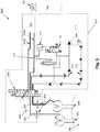
Figure 1 is a schematic illustration of a multimodal surgical gas delivery system for laparoscopic surgical procedures;Figure 2 is a schematic illustration of a multimodal surgical gas delivery system for laparoscopic surgical procedures; andFigure 3 is a schematic illustration of a multimodal surgical gas delivery system for laparoscopic surgical procedures.- Reference will now be made in detail to select embodiments of the invention, examples of which are illustrated in the accompanying drawings.
- The systems presented herein may be used for surgical gas delivery, including insufflation, smoke evacuation, and/or recirculation in connection with suitable surgical devices, and in applicable surgical procedures. The present invention is particularly suited for minimizing the amount of equipment needed in a surgical operating room (operating theater), in that the subject systems are capable of performing multiple functions, and therefore also allow flexibility of surgical technique.
Figures 1-3 illustrate different systems. Thesystem 100 ofFigure 1 illustrates a multimodal system adapted and configured to operate in any selected mode using three surgical devices that are in fluid connection with a surgical cavity 190 (e.g. a patient's abdominal cavity). Thesystem 200 ofFigure 2 andsystem 300 ofFigure 3 are each adapted and configured to operate in any selected mode using two surgical devices in fluid communication with asurgical cavity 190. In any case, it is conceived that additional surgical devices can be employed in parallel, for performing duplicative or still additional functions.- Such surgical devices can be any desired device capable of permitting fluid communication, including but not limited to standard surgical access devices (e.g. trocars, cannulas), veress needles, and the like. It is conceived that the subject systems can alternatively or additionally be adapted and configured to interface with a main lumen of such access devices by mounting to the proximal end portion thereof, or alternatively by a fluid conduit placed through the lumen of the access device. Such an arrangement may be desirable in cases where a volumetric flow of fluid to be passed through the system exceeds a capacity of an insufflation port and/or stopcock on a standard surgical access device. Typically, surgical access devices are provided with a stopcock arranged in fluid communication with a space defined below a seal element to permit connection to an insufflator.
- Systems described in
U.S. Patent Publication Number 2007/0088275 , as well as inU.S. Patent Application Serial Number 61/104,448, filed October 10, 2008 - Systems of the present invention utilize the inherent smoke and debris clearing capability of the systems configured for use with the aforementioned surgical access devices to perform additional functions with conventional access devices, including insufflation and smoke evacuation.
- As mentioned above, three main arrangements are described herein. The first arrangement enables smoke removal and insufflation using three conventional access devices. The second and third arrangements enable smoke removal and insufflation using only two conventional access devices.
- As illustrated in
Figure 1 , a multimodal surgicalgas delivery system 100 includes afluid pump 111 adapted and configured to circulate insufflation fluid through thesystem 100. Asupply conduit 114 is in fluid communication with an output of thefluid pump 111 and is configured and adapted for delivering pressurized insufflation fluid to anoutput port 183 of thecontrol unit 110. Areturn conduit 112 is in fluid communication with an input of thefluid pump 111 for delivering insufflation fluid to thefluid pump 111, and is configured and adapted for returning insufflation fluid to aninput port 181 of thecontrol unit 110. - An adjustable back-
pressure control valve 113 is provided in fluid communication with thesupply conduit 114 and thereturn conduit 112, and is adapted and configured to respond to a supply conduit pressure exceeding a set pressure, by opening and directing fluid from thesupply conduit 114 to thereturn conduit 112. The back-pressure control valve 113 can be a mechanical valve, such as a resiliently-biased valve. Alternatively, the back-pressure control valve 113 can be an electro-mechanical valve, responding to a high pressure signal from one or more pressure sensors (e.g. 117) within thesystem 100. - An
insufflation subunit 121 is provided and is adapted and configured to receive a supply of insufflation gas (e.g. carbon dioxide) from a source 140 (e.g. a local tank or central distribution system), which may also pass through apressure regulator 141 prior to entering thesystem 100. Theinsufflation subunit 121 is connected through aninsufflation conduit 118 for delivering insufflation gas to the rest of thesystem 100 from theinsufflation subunit 121, and includes a pressure sensor (not illustrated separately) adapted and configured to sense pressure of asurgical cavity 190 through the insufflation conduit, and an insufflation control (not illustrated separately), for controlling (as by stopping and starting) addition of insufflation fluid into thesystem 100, from thesource 140. - Further, the
system 100, or any system described herein, is controlled by a user through a control panel, such as one provided on or otherwise in connection with thecontrol unit 110. Such control panel is preferably adapted and configured to permit a user to select a mode for the multimodal surgical gas delivery system, such as by way of a switch, touch screen or other user interface, such as a graphical user interface (GUI) that permits flexibility of theunit 110, while reducing clutter and/or confusion due to excess controls, permitting only selection from a predetermined set of appropriate parameters in any given mode. After selecting a mode, such as insufflation only, smoke evacuation only, combined smoke evacuation and insufflation, recirculation only, or combined recirculation and smoke evacuation, for example, parameters that may be adjustable include, for example, flow rate (e.g. liters/minute), pressure (e.g. in mmHg), and conditioning parameters (e.g., temperature, humidity), and the like. As used herein, such "recirculation" mode, alone or combined with other modes, is one that is suitable for providing sufficient pressures and flow rates to drive surgical access devices such as those described inU.S. Patent Publication Number 2007/0088275 , as well as inU.S. Patent Application Serial Number 61/104,448, filed October 10, 2008 U.S. Patent Numbers 7,182,752 ,7,285,112 ,7,413,559 or7,338,473 , for example. - A conduit set or tube set 150 is also preferably provided, and is adapted and configured to connect at one end to the
supply 114, return 112 andinsufflation 118 conduits, and at the opposing end to a plurality ofsurgical devices surgical cavity 190. The configuration of the tube set 150 can vary, depending on the desired implementation, as mentioned above. In the case of thesystem 100 ofFigure 1 , the tube set 150 preferably has a unitary, multi-lumen connection to input 181,output 183 andinsufflation 185 ports, and separate connections to individualsurgical devices - In one preferred aspect, the tube set 150 has a compound, multi-lumen tube, beginning at the connections to the
ports control unit 110 for a predetermined distance from thecontrol unit 110, generally until about the distance between thecontrol unit 110 and an operating table, at which point afurcation 155 yields multiple separate tubes. In the case of thesystem 100 ofFigure 1 , three separate tubes, separately lead to each of thesurgical devices supply 114, return, 112 andinsufflation 118 conduits, and therefore respectively facilitates that function. That is, thesurgical devices abdominal cavity 190. - As set forth above, in one preferred aspect, the separate distal tube portions of the tube set 150 are connected by way of a conventional fitting, such as a luer-lock fitting on a conventional surgical device. The precise configuration of the tube set 150 can vary depending on the desired configuration. Moreover, as described for example, in U.S. Patent Application Serial Numbers
US 11/960,701, filed December 20, 2007 US 61/104,448, filed October 10, 2008 US 61/195,898, filed October 10, 2008 supply 114, return, 112 orinsufflation 118 conduits, and is (are) provided withintegral input 181,output 183 andinsufflation 185 ports, which can be a unitary, multi-lumen connection, for example. - A
filter 116 that is suitable for one application or function, may be suitable for use in another application or function. For example, a filter suitable for use in a recirculation function with specialized surgical access devices, such as Air Seal™ surgical cannulas, available from SurgiQuest, Inc., Orange, CT USA, as described in whole or in part inU.S. Pub. No. 2007/0088275 andUS 61/104,448, filed October 10, 2008 - Alternatively, a specially configured filter can be provided, with dimensions and other parameters tailored to flow rates of different functions. Moreover, the tube set 150 and filter 116 can be mutually configured as a set for a particular application and provided as a kit, and permanently connected, if desired.
- If so desired, systems in accordance with the invention can be provided with capability to automatically identify consumables (e.g., filters and/or tube sets) used in connection with the system, such as by a radio-frequency identification (RFID) transponder, bar code, or other data-carrying element provided thereon. In such an arrangement, the system (e.g. 100) identifies the consumable and switches to the appropriate mode (e.g., recirculation, smoke evacuation, etc.).
- The
system 100 ofFigure 1 includes anadditional dump valve 115 in connection with thefluid supply conduit 114. In addition to the short-circuiting action of the back-pressure control valve 113 described above, thesystem 100 is provided with apressure sensor 117, which can be mechanical but is, as illustrated, electronic. Thepressure sensor 117, if provided, is in fluid communication with theinsufflation conduit 118 or other source of abdominal pressure. When an over-pressure condition is sensed, thepressure sensor 117 signals thedump valve 115 to release fluid out of thesystem 100. As illustrated, thedump valve 115 is electro-mechanical, but alternatively may be fully mechanical, as desired. - One or more additional dump valves (e.g. dump valve 119) can be provided to reduce any possibility of overpressure conditions, and/or to provide redundancy for other safety features.
- In the embodiment of
Figure 1 , thesystem 100 operates, as set forth above, with onesurgical device 131 being used for insufflation and sensing functions, anothersurgical device 135 serving to remove insufflation gas from the abdomen, which then passes through a filter, such as an ultralow-penetration air ("ULPA")filter element 116 for example, before returning to thepump 111. Thefilter 116 is preferably configured and adapted to clear all or essentially all smoke and debris from the gas passing therethrough, with the gas being returned to theabdominal cavity 190 through a thirdsurgical device 133. As illustrated, anotherfilter element 116 can be provided in connection with thesupply conduit 114 leading from thepump 111. - For the purposes of explanation and illustration, and not limitation, a schematic illustration of an exemplary embodiment of a surgical gas delivery system in accordance with another aspect of the invention is shown in
Fig. 2 and is designated generally byreference character 200. As compared with thesystem 100 ofFigure 1 , thesystem 200 only requires two surgical devices (e.g., cannulas). The functionalities of components described above in connection with thesystem 100 ofFigure 1 are the same as the corresponding components of thesystem 200 ofFigure 2 , unless otherwise specified. - The
system 200 is in many ways similar to thesystem 100 ofFigure 1 , but with the addition of a divertingvalve 295, having threeconduits conduits surgical devices - As illustrated, the diverting
valve 295 is provided integrally, within thecontrol unit 210, as indicated schematically by placement of broken line referenced bynumber 210. The diverting valve is provided with three positions - positions, A, B and C, corresponding to different functions, as described below. When the sensing function of thesystem 200 is active, the divertingvalve 295 is positioned in, as illustrated, position "A", permitting connection of the insufflation/sensing conduit 118 therethrough, through one or both of theconduits surgical devices sensing conduit 118 to more than one surgical device, the potential for a lumen of such surgical device being blocked and thus not providing an accurate reading, is reduced. When the divertingvalve 295 is positioned at position A, and connects the insufflation/sensing conduit 118 to theconduits surgical devices insufflator subunit 121 is permitted to sense the abdominal pressure. In position A, output from thepump 111 enters the divertingvalve 295 and is returned to thepump 111 immediately by mutually connecting thesupply conduit 114 and returnconduit 112 under such circumstances. This configuration allows thepump 111 to continue running during sensing and thus avoids any power spikes which might occur if stopping and restarting of thepump 111. - If the
system 200 is set to a suitable mode (such as combined smoke evacuation and insufflation), when theinsufflator subunit 121 is finished sensing the abdominal pressure, the divertingvalve 295 is switched from position A, to Position B, in order to connect thesupply conduit 114 to acorresponding conduit 251 of the tube set 250, and thereturn conduit 112 to acorresponding conduit 253 of the tube set 250. In position B, theinsufflator conduit 118 is connected to thereturn conduit 112, permitting addition of insufflation gas into thesystem 200 through thereturn conduit 112. Concurrently, theinsufflator subunit 121 can be set to insufflating mode only, therefore only adding gas to thesystem 200 and not sensing pressures. - While in position B, the diverting
valve 295 permits delivery and return of fluid therethrough, between thepump 111 andfilters 216, and thesurgical devices surgical cavity 190. - If the pump and tube volume are considered as one controlled volume in conjunction with the volume of the
surgical cavity 190, the function of theinsufflator subunit 121 alone-switching from sensing to supplying carbon dioxide-is performed as in conventional surgical insufflators, in accordance with a preferred aspect. - Accordingly, as described above, in the
system 200 ofFigure 2 , smoke evacuation and filtration is only performed when the divertingvalve 295 permits theinsufflator control 121 to provide gas to thesurgical cavity 190. In such an arrangement, toggling to and from smoke evacuation/filtration and pressure sensing can be configured as either a normally sensing mode, or as a normally filtering mode, as desired or required. A normally sensing mode is likely to be preferred over a normally filtering mode, as monitoring of abdominal pressures is typically a priority. - As illustrated, position C of the diverting
valve 295 permits thesystem 200 to be operated in a recirculation mode, the recirculation mode being suitable for providing sufficient pressures and flow rates to drive surgical access devices such as those described inU.S. Patent Publication Number 2007/0088275 , as well as inU.S. Patent Application Serial Number 61/104,448, filed October 10, 2008 U.S. Patent Numbers 7,182,752 ,7,285,112 ,7,413,559 or7,338,473 , for example. In such a mode, a single tube of three lumens is typically provided, one lumen being in fluid communication with each of thesupply conduit 112, returnconduit 114 and theinsufflation conduit 118. - For the purposes of explanation and illustration, and not limitation, a schematic illustration of an exemplary embodiment of a surgical gas delivery system in accordance with still another aspect of the invention is shown in
Fig. 3 and is designated generally byreference character 300. - The functionality of components described above in connection with the
systems Figures 1 and2 , respectively are the same as the corresponding components of thesystem 300 ofFigure 3 , unless otherwise specified. - As with the
system 200 ofFigure 2 , thesystem 300 ofFigure 3 utilizes two separatefluid conduits surgical devices surgical cavity 190. Instead of a single insufflation/sense conduit 118, in thesystem 200 ofFigure 2 , a separatepressure sense conduit 318a and aninsufflation fluid conduit 318b are provided. The pressure sense andinsufflation fluid conduits insufflation subunit 121, through one ormore filters 216, and into a divertingvalve 395. Asupply conduit 114 and returnconduit 112 provided in connection with thepump 111 are also fed into the divertingvalve 395. This arrangement permits continuous addition of insufflation gas from thesupply 140, if necessary. - As illustrated, the diverting
valve 395 is provided with three positions, A, B and C. As illustrated inFigure 3 , invalve 395 position C, thepressure sense conduit 318a andinsufflation fluid conduit 318b are connected respectively to the two externalfluid conduits supply 114 and return 112 conduits are placed in fluid communication, bypassing thesurgical devices pump 111 may continue running and be re-activated in thesystem 300 by change in position of thevalve 395. In this manner, power spikes are avoided with repeated starting and stopping of thepump 111. - As illustrated, the diverting
valve 395 is provided integrally, within thecontrol unit 310, behindfilters 216, as schematically illustrated by placement of the broken line, referenced byelement number 310. - When the
insufflator control 121 is not sensing, the divertingvalve 395 is positioned in position B, in which theconduits surgical devices valve 395, with thesupply conduit 114 and returnconduit 112, and thus with thepump 111, in order to provide smoke removal function, for example. Withvalve 395 in position B, thepressure sense conduit 318a terminates at thevalve 395. In position B, supply of insufflation fluid can be provided by theinsufflation subunit 121, through theinsufflation conduit 318b, to thereturn line 112 to thepump 111, by way of the divertingvalve 395, permitting continuous addition of insufflation gas to thesystem 300, if necessary. By providing insufflation gas to thereturn line 112 to thepump 111, insufflation gas is injected into the controlled volume of the abdomen through thereturn line 112, to thepump 111. Alternatively, if so-desired, addition of insufflation gas can be provided on thesupply conduit 114 side of thepump 111. - In accordance with the invention, it is conceived that the rate of flow, which can be controlled by a user, is achieved, in one aspect, by the back-
pressure control valve 113, which can be embodied as an electro-mechanical valve to enable interface with an electronic control system, for example. - In general, flow to and from the
surgical devices 231, 235 for smoke evacuation/filtration functions will not solely affect pressure in thesurgical cavity 190, because absent addition of gas by theinsufflation subunit 121, only insufflation gas removed from the abdomen will be returned to the abdomen, and at the same flow rate. Otherwise, thepump 111 would become "starved." - As illustrated, position A of the diverting
valve 395 permits thesystem 300 to be operated in a recirculation mode, the recirculation mode being suitable for providing sufficient pressures and flow rates to drive surgical access devices such as those described inU.S. Patent Publication Number 2007/0088275 , as well as inU.S. Patent Application Serial Number 61/104,448, filed October 10, 2008 U.S. Patent Numbers 7,182,752 ,7,285,112 ,7,413,559 or7,338,473 , for example. In such a mode, a single tube of three lumens is typically provided, one lumen being in fluid communication with each of thesupply conduit 112, returnconduit 114 and theinsufflation conduit 118. - In accordance with the invention, it is conceived that the rate of flow for smoke evacuation may be considerably less than the amount of flow used to power surgical access devices, such as those described in
U.S. Pub. No. 2007/0088275 andUS 61/104,448, filed October 10, 2008 surgical cavity 190 may occur. Accordingly, integral flow restriction elements provided in connection with the tube sets 150, 250 or filter(s) 16 may be necessary to help reduce filtered gas flow.
Claims (3)
- A multimodal surgical gas delivery system comprising:- a fluid pump (111) adapted and configured to circulate insufflation fluid through the system;- a supply conduit (114) in fluid communication with an output of the fluid pump (111) and configured and adapted for delivering pressurized insufflation fluid to an output port (183) of a control unit (210; 310);- a return conduit (112) in fluid communication with an input of the fluid pump (111) for delivering insufflation fluid to the fluid pump (111) and configured and adapted for returning insufflation fluid to an input port (181) of the control unit (110);- an adjustable back-pressure control valve (113) in fluid communication with the supply conduit (114) and the return conduit (112), the back-pressure control valve (113) being adapted and configured to respond to a supply conduit pressure exceeding a set pressure by opening and directing fluid from the supply conduit (114) to the return conduit (112);- an insufflation control (121) for controlling addition of insufflation fluid into the system, from an insufflation gas source (140);- an insufflation conduit (118) for delivering insufflation gas to the system from the insufflation control (121);- a control panel configured and adapted to permit a user to select a mode of the multimodal surgical gas delivery system;- a conduit set (250), adapted and configured to connect to the supply, return and insufflation conduits (114, 112, 118), and to a plurality of surgical devices (231, 233) in fluid communication with the surgical cavity,- a pressure sensor (117), adapted and configured to sense pressure of a surgical cavity (190) through the insufflation conduit (118); and- a dump valve (115) in fluid communication with the supply conduit (114) adapted and configured to release fluid from the system when an over-pressure condition is sensed,characterized by
a switching valve (295; 395) in connection with the supply, return and insufflation conduits (114, 112, 118), the switching valve (295; 395) being configured and adapted to divert the insufflation conduit (118) between fluid connection with one or more of the surgical devices (231, 233), and the return conduit (112) to the fluid pump (111). - The system of claim 1, wherein the insufflation conduit (118) serves as a conduit for detecting abdominal pressure.
- The system of claim 1, further comprising a conduit (318a) for detecting abdominal pressure, separate from the insufflation conduit (118).
Applications Claiming Priority (2)
| Application Number | Priority Date | Filing Date | Title |
|---|---|---|---|
| US24692109P | 2009-09-29 | 2009-09-29 | |
| PCT/US2010/050688WO2011041387A1 (en) | 2009-09-29 | 2010-09-29 | Multimodal surgical gas delivery system for laparoscopic surgical procedures |
Publications (2)
| Publication Number | Publication Date |
|---|---|
| EP2482869A1 EP2482869A1 (en) | 2012-08-08 |
| EP2482869B1true EP2482869B1 (en) | 2019-09-25 |
Family
ID=43270412
Family Applications (1)
| Application Number | Title | Priority Date | Filing Date |
|---|---|---|---|
| EP10770662.4AActiveEP2482869B1 (en) | 2009-09-29 | 2010-09-29 | Multimodal surgical gas delivery system for laparoscopic surgical procedures |
Country Status (4)
| Country | Link |
|---|---|
| EP (1) | EP2482869B1 (en) |
| JP (1) | JP5671542B2 (en) |
| ES (1) | ES2763362T3 (en) |
| WO (1) | WO2011041387A1 (en) |
Families Citing this family (20)
| Publication number | Priority date | Publication date | Assignee | Title |
|---|---|---|---|---|
| WO2010068265A1 (en) | 2008-12-10 | 2010-06-17 | Minimally Invasive Devices, Llc | Systems and methods for optimizing and maintaining visualization of a surgical field during the use of surgical scopes |
| US9078562B2 (en) | 2010-01-11 | 2015-07-14 | Minimally Invasive Devices, Inc. | Systems and methods for optimizing and maintaining visualization of a surgical field during the use of surgical scopes |
| JP5968886B2 (en) | 2010-08-04 | 2016-08-10 | ミニマリー インべーシブ デバイシーズ, インコーポレイテッド | System and method for optimizing and maintaining operative field visualization while using a surgical microscope |
| US11147934B2 (en) | 2010-09-20 | 2021-10-19 | Conmed Corporation | System and method for launching usage mode in a multimodal surgical gas delivery system |
| WO2012044410A2 (en) | 2010-09-20 | 2012-04-05 | Surgiquest, Inc. | Multi-flow filtration system |
| US9522017B2 (en) | 2010-12-03 | 2016-12-20 | Minimally Invasive Devices, Inc. | Devices, systems, and methods for performing endoscopic surgical procedures |
| WO2014151824A1 (en) | 2013-03-14 | 2014-09-25 | Minimally Invasive Devices, Inc. | Fluid dispensing control systems and methods |
| CN105431093B (en)* | 2013-08-06 | 2019-03-29 | 奥林巴斯株式会社 | Pneumoperitoneum device |
| DE102013016063A1 (en)* | 2013-09-27 | 2015-04-02 | W. O. M. World of Medicine GmbH | Pressure-retaining smoke evacuation in an insufflator |
| WO2017004490A1 (en)* | 2015-07-02 | 2017-01-05 | Northgate Technologies Inc. | Gas recirculation system |
| WO2017057065A1 (en)* | 2015-10-01 | 2017-04-06 | オリンパス株式会社 | Circulation smoke extraction system |
| US10427654B2 (en) | 2016-07-19 | 2019-10-01 | Norco Industries, Inc. | Three point vehicle leveling with multi point stabilizing systems |
| AU2017357113B2 (en)* | 2016-11-14 | 2020-07-02 | Conmed Corporation | Multimodal surgical gas delivery system configured to maintain stable body cavity pressure when suction is used in the body cavity |
| US11147935B2 (en) | 2016-11-14 | 2021-10-19 | Conmed Corporation | Smoke evacuation system for continuously removing gas from a body cavity |
| WO2018089986A2 (en) | 2016-11-14 | 2018-05-17 | Conmed Corporation | Multimodal surgical gas delivery system having continuous pressure monitoring of a continuous flow of gas to a body cavity |
| DE102016014980A1 (en) | 2016-12-16 | 2018-06-21 | W.O.M. World Of Medicine Gmbh | Medical pump with improved ventilation |
| US10806490B2 (en)* | 2017-03-08 | 2020-10-20 | Conmed Corporation | Single lumen gas sealed access port for use during endoscopic surgical procedures |
| DE102018004211A1 (en) | 2018-05-25 | 2019-11-28 | W.O.M. World Of Medicine Gmbh | Insufflation device and thus feasible operating procedures |
| DE102021002547A1 (en) | 2021-05-17 | 2022-11-17 | W.O.M. World Of Medicine Gmbh | Medical technology pump for endoscopy |
| WO2024231909A2 (en)* | 2023-05-08 | 2024-11-14 | Palliare Limited | An insufflator, an insufflating system and a method for insufflating a cavity in the body of a human or animal subject |
Family Cites Families (7)
| Publication number | Priority date | Publication date | Assignee | Title |
|---|---|---|---|---|
| JP2551183Y2 (en)* | 1991-07-31 | 1997-10-22 | 株式会社長野計器製作所 | Insufflation device |
| US7854724B2 (en)* | 2003-04-08 | 2010-12-21 | Surgiquest, Inc. | Trocar assembly with pneumatic sealing |
| WO2006064713A1 (en)* | 2004-12-15 | 2006-06-22 | Olympus Medical Systems Corp. | Gas supply device, method of controlling gas supply device, gas supply system, and endoscope system |
| EP2101662B1 (en)* | 2006-12-18 | 2018-07-11 | SurgiQuest, Incorporated | System for surgical insufflation and gas recirculation |
| EP2134238B1 (en) | 2007-04-17 | 2016-08-03 | SurgiQuest, Incorporated | Endoluminal and transluminal surgical devices |
| US8028712B2 (en)* | 2008-05-08 | 2011-10-04 | Tyco Valves & Controls Lp | Diaphragm controlled bypass valve |
| CN206348788U (en) | 2017-01-06 | 2017-07-21 | 台达电子工业股份有限公司 | USB control device |
- 2010
- 2010-09-29WOPCT/US2010/050688patent/WO2011041387A1/enactiveApplication Filing
- 2010-09-29ESES10770662Tpatent/ES2763362T3/enactiveActive
- 2010-09-29EPEP10770662.4Apatent/EP2482869B1/enactiveActive
- 2010-09-29JPJP2012532265Apatent/JP5671542B2/enactiveActive
Non-Patent Citations (1)
| Title |
|---|
| None* |
Also Published As
| Publication number | Publication date |
|---|---|
| JP2013505812A (en) | 2013-02-21 |
| JP5671542B2 (en) | 2015-02-18 |
| EP2482869A1 (en) | 2012-08-08 |
| WO2011041387A1 (en) | 2011-04-07 |
| ES2763362T3 (en) | 2020-05-28 |
Similar Documents
| Publication | Publication Date | Title |
|---|---|---|
| EP2482869B1 (en) | Multimodal surgical gas delivery system for laparoscopic surgical procedures | |
| EP2618887B1 (en) | Multimodal surgical gas delivery system for laparoscopic surgical procedures | |
| US11147935B2 (en) | Smoke evacuation system for continuously removing gas from a body cavity | |
| US12005183B2 (en) | Systems and methods for conducting smoke evacuation during laparoscopic surgical procedures | |
| US11033299B2 (en) | Multimodal surgical gas delivery system having continuous pressure monitoring of a continuous flow of gas to a body cavity | |
| EP3250274B1 (en) | Filter cartridge with internal gaseous seal for multimodal surgical gas delivery system having a smoke evacuation mode | |
| EP3316805B1 (en) | Multipath filter assembly with integrated gaseous seal for multimodal surgical gas delivery system | |
| EP3206604B1 (en) | Branching multi-lumen tube set for laparoscopic surgical procedures involving smoke evacuation | |
| HK1169344B (en) | Multimodal surgical gas delivery system for laparoscopic surgical procedures | |
| HK1169344A (en) | Multimodal surgical gas delivery system for laparoscopic surgical procedures | |
| HK40047496A (en) | Systems for conducting smoke evacuation during laparoscopic surgical procedures | |
| HK40047496B (en) | Systems for conducting smoke evacuation during laparoscopic surgical procedures |
Legal Events
| Date | Code | Title | Description |
|---|---|---|---|
| PUAI | Public reference made under article 153(3) epc to a published international application that has entered the european phase | Free format text:ORIGINAL CODE: 0009012 | |
| 17P | Request for examination filed | Effective date:20120322 | |
| AK | Designated contracting states | Kind code of ref document:A1 Designated state(s):AL AT BE BG CH CY CZ DE DK EE ES FI FR GB GR HR HU IE IS IT LI LT LU LV MC MK MT NL NO PL PT RO SE SI SK SM TR | |
| DAX | Request for extension of the european patent (deleted) | ||
| REG | Reference to a national code | Ref country code:HK Ref legal event code:DE Ref document number:1169344 Country of ref document:HK | |
| 17Q | First examination report despatched | Effective date:20160915 | |
| STAA | Information on the status of an ep patent application or granted ep patent | Free format text:STATUS: EXAMINATION IS IN PROGRESS | |
| REG | Reference to a national code | Ref country code:DE Ref legal event code:R079 Ref document number:602010061231 Country of ref document:DE Free format text:PREVIOUS MAIN CLASS: A61M0003000000 Ipc:A61M0013000000 | |
| GRAP | Despatch of communication of intention to grant a patent | Free format text:ORIGINAL CODE: EPIDOSNIGR1 | |
| STAA | Information on the status of an ep patent application or granted ep patent | Free format text:STATUS: GRANT OF PATENT IS INTENDED | |
| RIC1 | Information provided on ipc code assigned before grant | Ipc:A61M 13/00 20060101AFI20190311BHEP | |
| INTG | Intention to grant announced | Effective date:20190411 | |
| RIN1 | Information on inventor provided before grant (corrected) | Inventor name:TANG, RAYMOND, YUE-SING Inventor name:FELDMAN, DENNIS Inventor name:STEARNS, RALPH | |
| GRAS | Grant fee paid | Free format text:ORIGINAL CODE: EPIDOSNIGR3 | |
| GRAA | (expected) grant | Free format text:ORIGINAL CODE: 0009210 | |
| STAA | Information on the status of an ep patent application or granted ep patent | Free format text:STATUS: THE PATENT HAS BEEN GRANTED | |
| AK | Designated contracting states | Kind code of ref document:B1 Designated state(s):AL AT BE BG CH CY CZ DE DK EE ES FI FR GB GR HR HU IE IS IT LI LT LU LV MC MK MT NL NO PL PT RO SE SI SK SM TR | |
| REG | Reference to a national code | Ref country code:GB Ref legal event code:FG4D | |
| REG | Reference to a national code | Ref country code:CH Ref legal event code:EP | |
| REG | Reference to a national code | Ref country code:AT Ref legal event code:REF Ref document number:1183207 Country of ref document:AT Kind code of ref document:T Effective date:20191015 | |
| REG | Reference to a national code | Ref country code:IE Ref legal event code:FG4D | |
| REG | Reference to a national code | Ref country code:DE Ref legal event code:R096 Ref document number:602010061231 Country of ref document:DE | |
| REG | Reference to a national code | Ref country code:NL Ref legal event code:MP Effective date:20190925 | |
| PG25 | Lapsed in a contracting state [announced via postgrant information from national office to epo] | Ref country code:NO Free format text:LAPSE BECAUSE OF FAILURE TO SUBMIT A TRANSLATION OF THE DESCRIPTION OR TO PAY THE FEE WITHIN THE PRESCRIBED TIME-LIMIT Effective date:20191225 Ref country code:BG Free format text:LAPSE BECAUSE OF FAILURE TO SUBMIT A TRANSLATION OF THE DESCRIPTION OR TO PAY THE FEE WITHIN THE PRESCRIBED TIME-LIMIT Effective date:20191225 Ref country code:HR Free format text:LAPSE BECAUSE OF FAILURE TO SUBMIT A TRANSLATION OF THE DESCRIPTION OR TO PAY THE FEE WITHIN THE PRESCRIBED TIME-LIMIT Effective date:20190925 Ref country code:LT Free format text:LAPSE BECAUSE OF FAILURE TO SUBMIT A TRANSLATION OF THE DESCRIPTION OR TO PAY THE FEE WITHIN THE PRESCRIBED TIME-LIMIT Effective date:20190925 Ref country code:FI Free format text:LAPSE BECAUSE OF FAILURE TO SUBMIT A TRANSLATION OF THE DESCRIPTION OR TO PAY THE FEE WITHIN THE PRESCRIBED TIME-LIMIT Effective date:20190925 Ref country code:SE Free format text:LAPSE BECAUSE OF FAILURE TO SUBMIT A TRANSLATION OF THE DESCRIPTION OR TO PAY THE FEE WITHIN THE PRESCRIBED TIME-LIMIT Effective date:20190925 | |
| REG | Reference to a national code | Ref country code:LT Ref legal event code:MG4D | |
| PG25 | Lapsed in a contracting state [announced via postgrant information from national office to epo] | Ref country code:GR Free format text:LAPSE BECAUSE OF FAILURE TO SUBMIT A TRANSLATION OF THE DESCRIPTION OR TO PAY THE FEE WITHIN THE PRESCRIBED TIME-LIMIT Effective date:20191226 Ref country code:LV Free format text:LAPSE BECAUSE OF FAILURE TO SUBMIT A TRANSLATION OF THE DESCRIPTION OR TO PAY THE FEE WITHIN THE PRESCRIBED TIME-LIMIT Effective date:20190925 | |
| REG | Reference to a national code | Ref country code:AT Ref legal event code:MK05 Ref document number:1183207 Country of ref document:AT Kind code of ref document:T Effective date:20190925 | |
| PG25 | Lapsed in a contracting state [announced via postgrant information from national office to epo] | Ref country code:RO Free format text:LAPSE BECAUSE OF FAILURE TO SUBMIT A TRANSLATION OF THE DESCRIPTION OR TO PAY THE FEE WITHIN THE PRESCRIBED TIME-LIMIT Effective date:20190925 Ref country code:AL Free format text:LAPSE BECAUSE OF FAILURE TO SUBMIT A TRANSLATION OF THE DESCRIPTION OR TO PAY THE FEE WITHIN THE PRESCRIBED TIME-LIMIT Effective date:20190925 Ref country code:PL Free format text:LAPSE BECAUSE OF FAILURE TO SUBMIT A TRANSLATION OF THE DESCRIPTION OR TO PAY THE FEE WITHIN THE PRESCRIBED TIME-LIMIT Effective date:20190925 Ref country code:AT Free format text:LAPSE BECAUSE OF FAILURE TO SUBMIT A TRANSLATION OF THE DESCRIPTION OR TO PAY THE FEE WITHIN THE PRESCRIBED TIME-LIMIT Effective date:20190925 Ref country code:EE Free format text:LAPSE BECAUSE OF FAILURE TO SUBMIT A TRANSLATION OF THE DESCRIPTION OR TO PAY THE FEE WITHIN THE PRESCRIBED TIME-LIMIT Effective date:20190925 Ref country code:PT Free format text:LAPSE BECAUSE OF FAILURE TO SUBMIT A TRANSLATION OF THE DESCRIPTION OR TO PAY THE FEE WITHIN THE PRESCRIBED TIME-LIMIT Effective date:20200127 Ref country code:NL Free format text:LAPSE BECAUSE OF FAILURE TO SUBMIT A TRANSLATION OF THE DESCRIPTION OR TO PAY THE FEE WITHIN THE PRESCRIBED TIME-LIMIT Effective date:20190925 | |
| REG | Reference to a national code | Ref country code:ES Ref legal event code:FG2A Ref document number:2763362 Country of ref document:ES Kind code of ref document:T3 Effective date:20200528 | |
| PG25 | Lapsed in a contracting state [announced via postgrant information from national office to epo] | Ref country code:CZ Free format text:LAPSE BECAUSE OF FAILURE TO SUBMIT A TRANSLATION OF THE DESCRIPTION OR TO PAY THE FEE WITHIN THE PRESCRIBED TIME-LIMIT Effective date:20190925 Ref country code:IS Free format text:LAPSE BECAUSE OF FAILURE TO SUBMIT A TRANSLATION OF THE DESCRIPTION OR TO PAY THE FEE WITHIN THE PRESCRIBED TIME-LIMIT Effective date:20200224 Ref country code:SK Free format text:LAPSE BECAUSE OF FAILURE TO SUBMIT A TRANSLATION OF THE DESCRIPTION OR TO PAY THE FEE WITHIN THE PRESCRIBED TIME-LIMIT Effective date:20190925 Ref country code:SM Free format text:LAPSE BECAUSE OF FAILURE TO SUBMIT A TRANSLATION OF THE DESCRIPTION OR TO PAY THE FEE WITHIN THE PRESCRIBED TIME-LIMIT Effective date:20190925 | |
| REG | Reference to a national code | Ref country code:CH Ref legal event code:PL | |
| REG | Reference to a national code | Ref country code:DE Ref legal event code:R097 Ref document number:602010061231 Country of ref document:DE | |
| PG2D | Information on lapse in contracting state deleted | Ref country code:IS | |
| PG25 | Lapsed in a contracting state [announced via postgrant information from national office to epo] | Ref country code:LU Free format text:LAPSE BECAUSE OF NON-PAYMENT OF DUE FEES Effective date:20190929 Ref country code:DK Free format text:LAPSE BECAUSE OF FAILURE TO SUBMIT A TRANSLATION OF THE DESCRIPTION OR TO PAY THE FEE WITHIN THE PRESCRIBED TIME-LIMIT Effective date:20190925 Ref country code:IE Free format text:LAPSE BECAUSE OF NON-PAYMENT OF DUE FEES Effective date:20190929 Ref country code:CH Free format text:LAPSE BECAUSE OF NON-PAYMENT OF DUE FEES Effective date:20190930 Ref country code:LI Free format text:LAPSE BECAUSE OF NON-PAYMENT OF DUE FEES Effective date:20190930 Ref country code:IS Free format text:LAPSE BECAUSE OF FAILURE TO SUBMIT A TRANSLATION OF THE DESCRIPTION OR TO PAY THE FEE WITHIN THE PRESCRIBED TIME-LIMIT Effective date:20200126 | |
| PLBE | No opposition filed within time limit | Free format text:ORIGINAL CODE: 0009261 | |
| STAA | Information on the status of an ep patent application or granted ep patent | Free format text:STATUS: NO OPPOSITION FILED WITHIN TIME LIMIT | |
| REG | Reference to a national code | Ref country code:BE Ref legal event code:MM Effective date:20190930 | |
| PG25 | Lapsed in a contracting state [announced via postgrant information from national office to epo] | Ref country code:BE Free format text:LAPSE BECAUSE OF NON-PAYMENT OF DUE FEES Effective date:20190930 Ref country code:MC Free format text:LAPSE BECAUSE OF FAILURE TO SUBMIT A TRANSLATION OF THE DESCRIPTION OR TO PAY THE FEE WITHIN THE PRESCRIBED TIME-LIMIT Effective date:20190925 | |
| 26N | No opposition filed | Effective date:20200626 | |
| PG25 | Lapsed in a contracting state [announced via postgrant information from national office to epo] | Ref country code:SI Free format text:LAPSE BECAUSE OF FAILURE TO SUBMIT A TRANSLATION OF THE DESCRIPTION OR TO PAY THE FEE WITHIN THE PRESCRIBED TIME-LIMIT Effective date:20190925 | |
| PG25 | Lapsed in a contracting state [announced via postgrant information from national office to epo] | Ref country code:CY Free format text:LAPSE BECAUSE OF FAILURE TO SUBMIT A TRANSLATION OF THE DESCRIPTION OR TO PAY THE FEE WITHIN THE PRESCRIBED TIME-LIMIT Effective date:20190925 | |
| PG25 | Lapsed in a contracting state [announced via postgrant information from national office to epo] | Ref country code:HU Free format text:LAPSE BECAUSE OF FAILURE TO SUBMIT A TRANSLATION OF THE DESCRIPTION OR TO PAY THE FEE WITHIN THE PRESCRIBED TIME-LIMIT; INVALID AB INITIO Effective date:20100929 Ref country code:MT Free format text:LAPSE BECAUSE OF FAILURE TO SUBMIT A TRANSLATION OF THE DESCRIPTION OR TO PAY THE FEE WITHIN THE PRESCRIBED TIME-LIMIT Effective date:20190925 | |
| PG25 | Lapsed in a contracting state [announced via postgrant information from national office to epo] | Ref country code:TR Free format text:LAPSE BECAUSE OF FAILURE TO SUBMIT A TRANSLATION OF THE DESCRIPTION OR TO PAY THE FEE WITHIN THE PRESCRIBED TIME-LIMIT Effective date:20190925 | |
| PG25 | Lapsed in a contracting state [announced via postgrant information from national office to epo] | Ref country code:MK Free format text:LAPSE BECAUSE OF FAILURE TO SUBMIT A TRANSLATION OF THE DESCRIPTION OR TO PAY THE FEE WITHIN THE PRESCRIBED TIME-LIMIT Effective date:20190925 | |
| PGFP | Annual fee paid to national office [announced via postgrant information from national office to epo] | Ref country code:DE Payment date:20240806 Year of fee payment:15 | |
| PGFP | Annual fee paid to national office [announced via postgrant information from national office to epo] | Ref country code:GB Payment date:20240808 Year of fee payment:15 | |
| PGFP | Annual fee paid to national office [announced via postgrant information from national office to epo] | Ref country code:FR Payment date:20240808 Year of fee payment:15 | |
| PGFP | Annual fee paid to national office [announced via postgrant information from national office to epo] | Ref country code:IT Payment date:20240812 Year of fee payment:15 | |
| PGFP | Annual fee paid to national office [announced via postgrant information from national office to epo] | Ref country code:ES Payment date:20241003 Year of fee payment:15 |