EP2481279B1 - Interlocking plant propagation and display tray and method of use and assembly - Google Patents
Interlocking plant propagation and display tray and method of use and assemblyDownload PDFInfo
- Publication number
- EP2481279B1 EP2481279B1EP20120153326EP12153326AEP2481279B1EP 2481279 B1EP2481279 B1EP 2481279B1EP 20120153326EP20120153326EP 20120153326EP 12153326 AEP12153326 AEP 12153326AEP 2481279 B1EP2481279 B1EP 2481279B1
- Authority
- EP
- European Patent Office
- Prior art keywords
- tray
- wall
- back wall
- plant
- trays
- Prior art date
- Legal status (The legal status is an assumption and is not a legal conclusion. Google has not performed a legal analysis and makes no representation as to the accuracy of the status listed.)
- Active
Links
- 238000000034methodMethods0.000titledescription9
- XLYOFNOQVPJJNP-UHFFFAOYSA-NwaterSubstancesOXLYOFNOQVPJJNP-UHFFFAOYSA-N0.000claimsdescription30
- 230000002262irrigationEffects0.000claimsdescription4
- 238000003973irrigationMethods0.000claimsdescription4
- 230000008878couplingEffects0.000claimsdescription2
- 238000010168coupling processMethods0.000claimsdescription2
- 238000005859coupling reactionMethods0.000claimsdescription2
- 238000010438heat treatmentMethods0.000claimsdescription2
- 241000196324EmbryophytaSpecies0.000description84
- 239000000463materialSubstances0.000description7
- 230000008901benefitEffects0.000description6
- 238000013461designMethods0.000description6
- -1polypropylenePolymers0.000description4
- 239000002689soilSubstances0.000description4
- 230000006978adaptationEffects0.000description3
- 239000000654additiveSubstances0.000description3
- 238000010276constructionMethods0.000description3
- 239000003000extruded plasticSubstances0.000description3
- 230000012010growthEffects0.000description3
- 238000010899nucleationMethods0.000description3
- 230000008635plant growthEffects0.000description3
- 239000004698PolyethyleneSubstances0.000description2
- 239000004743PolypropyleneSubstances0.000description2
- 230000005484gravityEffects0.000description2
- 238000011065in-situ storageMethods0.000description2
- 238000009434installationMethods0.000description2
- 239000004033plasticSubstances0.000description2
- 229920003023plasticPolymers0.000description2
- 229920000573polyethylenePolymers0.000description2
- 229920000139polyethylene terephthalatePolymers0.000description2
- 239000005020polyethylene terephthalateSubstances0.000description2
- 229920001155polypropylenePolymers0.000description2
- 239000004810polytetrafluoroethyleneSubstances0.000description2
- 229920001343polytetrafluoroethylenePolymers0.000description2
- 238000002791soakingMethods0.000description2
- 241000894007speciesSpecies0.000description2
- 239000004604Blowing AgentSubstances0.000description1
- OKTJSMMVPCPJKN-UHFFFAOYSA-NCarbonChemical compound[C]OKTJSMMVPCPJKN-UHFFFAOYSA-N0.000description1
- 239000004605External LubricantSubstances0.000description1
- 239000004606Fillers/ExtendersSubstances0.000description1
- 239000004609Impact ModifierSubstances0.000description1
- 239000004610Internal LubricantSubstances0.000description1
- 239000004793PolystyreneSubstances0.000description1
- 239000004614Process AidSubstances0.000description1
- 238000010521absorption reactionMethods0.000description1
- XAGFODPZIPBFFR-UHFFFAOYSA-NaluminiumChemical compound[Al]XAGFODPZIPBFFR-UHFFFAOYSA-N0.000description1
- 229910052782aluminiumInorganic materials0.000description1
- 239000004411aluminiumSubstances0.000description1
- 230000000845anti-microbial effectEffects0.000description1
- 239000004599antimicrobialSubstances0.000description1
- 239000003963antioxidant agentSubstances0.000description1
- 239000002216antistatic agentSubstances0.000description1
- 230000000712assemblyEffects0.000description1
- 238000000429assemblyMethods0.000description1
- 239000004600biostabiliserSubstances0.000description1
- 229910052799carbonInorganic materials0.000description1
- 238000007796conventional methodMethods0.000description1
- 230000005574cross-species transmissionEffects0.000description1
- 238000009826distributionMethods0.000description1
- 230000000694effectsEffects0.000description1
- 238000005516engineering processMethods0.000description1
- 239000000945fillerSubstances0.000description1
- 239000003063flame retardantSubstances0.000description1
- 239000003205fragranceSubstances0.000description1
- 239000005431greenhouse gasSubstances0.000description1
- 230000036541healthEffects0.000description1
- 239000012760heat stabilizerSubstances0.000description1
- 239000003864humusSubstances0.000description1
- 238000009413insulationMethods0.000description1
- 238000005304joiningMethods0.000description1
- 239000004611light stabiliserSubstances0.000description1
- 238000012423maintenanceMethods0.000description1
- 230000013011matingEffects0.000description1
- 230000007246mechanismEffects0.000description1
- 238000012986modificationMethods0.000description1
- 230000004048modificationEffects0.000description1
- 238000012544monitoring processMethods0.000description1
- 235000015097nutrientsNutrition0.000description1
- 238000005192partitionMethods0.000description1
- 239000000049pigmentSubstances0.000description1
- 239000004014plasticizerSubstances0.000description1
- 239000004417polycarbonateSubstances0.000description1
- 229920000515polycarbonatePolymers0.000description1
- 239000004814polyurethaneSubstances0.000description1
- 239000004800polyvinyl chlorideSubstances0.000description1
- 238000011176poolingMethods0.000description1
- 238000002360preparation methodMethods0.000description1
- 230000001737promoting effectEffects0.000description1
- 238000005096rolling processMethods0.000description1
- 229910001220stainless steelInorganic materials0.000description1
- 239000010935stainless steelSubstances0.000description1
- 239000000126substanceSubstances0.000description1
- 238000006467substitution reactionMethods0.000description1
- 239000000758substrateSubstances0.000description1
- 239000004557technical materialSubstances0.000description1
- 230000003442weekly effectEffects0.000description1
Images


Classifications
- A—HUMAN NECESSITIES
- A01—AGRICULTURE; FORESTRY; ANIMAL HUSBANDRY; HUNTING; TRAPPING; FISHING
- A01G—HORTICULTURE; CULTIVATION OF VEGETABLES, FLOWERS, RICE, FRUIT, VINES, HOPS OR SEAWEED; FORESTRY; WATERING
- A01G9/00—Cultivation in receptacles, forcing-frames or greenhouses; Edging for beds, lawn or the like
- A01G9/02—Receptacles, e.g. flower-pots or boxes; Glasses for cultivating flowers
- A01G9/022—Pots for vertical horticulture
- A01G9/025—Containers and elements for greening walls
- Y—GENERAL TAGGING OF NEW TECHNOLOGICAL DEVELOPMENTS; GENERAL TAGGING OF CROSS-SECTIONAL TECHNOLOGIES SPANNING OVER SEVERAL SECTIONS OF THE IPC; TECHNICAL SUBJECTS COVERED BY FORMER USPC CROSS-REFERENCE ART COLLECTIONS [XRACs] AND DIGESTS
- Y02—TECHNOLOGIES OR APPLICATIONS FOR MITIGATION OR ADAPTATION AGAINST CLIMATE CHANGE
- Y02P—CLIMATE CHANGE MITIGATION TECHNOLOGIES IN THE PRODUCTION OR PROCESSING OF GOODS
- Y02P60/00—Technologies relating to agriculture, livestock or agroalimentary industries
- Y02P60/20—Reduction of greenhouse gas [GHG] emissions in agriculture, e.g. CO2
Definitions
- the present inventionrelates to green walls and in particular to plant propagation and display trays and assemblies.
- seeding and planting panelshave been used for greening surfaces of permanent constructions such as buildings, retaining walls, and the like.
- These seeding and planting panelsgenerally include a panel frame, and a seeding and planting mat or block contained within the frame.
- these types of panel framesare fixedly secured to surfaces of existing constructions such as building wall surfaces, roofs or retaining walls, and are integrally incorporated into the constructions so as to be permanent structural elements thereof. It is very cumbersome to exchange these panels as they are not easily disengaged from their supports and removed. In addition, as the backside faces of the panels are concealed, general maintenance work is very difficult.
- Document US-A-2011016784discloses a plant propagation and display tray, which is capable of interlocking alignement with at least one other tray and which is capable of receiving and holding at least one plant pot, comprising a back wall and a bottom ledge towardly projecting from said back wall.
- the present inventionprovides a plant propagation and display tray, which is capable of interlocking alignment with at least one other tray and which is capable of receiving and holding at least one plant pot, comprises a back wall and a bottom ledge forwardly projecting from said back wall; said ledge being inclined towards the back wall and comprising a plurality of alternating projections and troughs, each of said troughs inclining towards a trough point of abutment with the back wall and being of a conformation to securably hold one plant pot such that an open proximal end of the plant pot is exposed to view and a distal end of the plant pot is adjacent to the back wall; each of said projections having an upper surface which inclines towards a projection point of abutment with the back wall, wherein the projection point of abutment is higher than the trough point of abutment with the back wall; wherein said tray is capable of being attached to a wall surface.
- the present inventionfurther provides a planter wall formed of a plurality of interlocking trays as described above, one above another, and/or one beside another and attached to a wall surface.
- the tray of the present inventionoffers a multitude of advantages not found in any prior green wall system.
- the provision of the alternating troughs and projections on the ledge, and the inclinations of each "backwards" i.e. to the direction of the back wallcontrols water delivery to the plants (in the pots), once such plants are in place within the troughs.
- the body of the projectionsessentially takes up space where water would otherwise pool.
- the base of a plant pot, once in place,is thereby only exposed to enough water to allow wicking, while avoiding soaking. This reduces or eliminates problems such as rot.
- many plant varietiesdo not thrive being watered from the top.
- the design and conformation of the tray in accordance with the present inventionallows interlocking placement of a plurality of trays, one above the other, or one beside another and all attached to a wall surface thereby forming, once plant pots are inserted, a "green wall".
- wateringmay be accomplished by the use of gravity.
- the system of the present inventionis highly adaptable to a wide variety of green wall installations.
- the present inventionprovides, in one aspect, a plant propagation and display tray which provides several key advantages including the provision, by way of a unique configuration of troughs and projections, of a zone for placement of plant pots around which water does not unnecessarily pool.
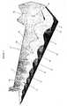
- the plant propagation and display tray 10comprises a back wall 12 and a bottom ledge 14 forwardly projecting from said back wall.
- the "back wall”refers to the moiety of the tray that, in use, will abut the structure against which the planter wall is to be placed.
- Ledge 14is inclined towards the back wall and comprises a plurality of alternating projections, 16 and troughs 18, with each of troughs 18 inclining towards a trough point of abutment, 20 with the back wall.
- Troughs 18are of a conformation to securably hold one plant pot, (shown in 10, 11, 12 and 13, among other figures) such that an open proximal end of the plant pot is exposed to view and a distal end of the plant pot is adjacent to the back wall.
- Each of projections 16have an upper surface 22 which inclines towards a projection point of abutment 24 with the back wall, wherein the projection point of abutment 24 is generally higher than the trough point of abutment 20 with the back wall. The purpose for this design will be described further below.
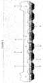
- Back wall 12comprises a substantially flat upper portion 26 and a lower portion, adjacent the ledge, which is thicker than the upper portion and which is defined by a plurality of substantially V-shaped depressions, 28, each of which points towards a trough on the ledge.
- the reverse side of back wall 12is depicted in Figure 4 which shows a substantially flat surface for alignment with a wall surface, when the tray is in use.
- traysmay be of varying lengths and comprise differing numbers of plant-pot receiving troughs.
- the tray in Figure 1depicts 8 plant-pot receiving troughs.
- traysare depicted with 8, 3 and 1 plant-pot receiving troughs.
- Female alignment member 30is shown in Figures 1-4 , integrally formed as part of back wall 12. Similarly male alignment member 32 is best shown in Figure 4 .
- each such trayis aligned in the correct position, relative to the trays above and below, by use of the male and female alignment members. More specifically, for tray 36, female alignment member 30 is engaged by male alignment member 32 of tray 38. This alignment obviates the need for any other measuring means to ensure accurate vertical stacking of more than one tray.
- Holes 40are provided on each tray for pass through by screws, nails or other means of securing the tray to a wall surface.
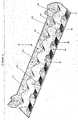
- Figure 5is useful to show the alternating arrangement of projections 16 and troughs 18 and the preferred shape and inclination of those features towards back wall 12.
- Troughs 18incline to trough points of abutment 20 and are of a conformation which is acceptable to receive and securably hold a desired size of plant pot 42 ( Figures 11 and 12 , among other figures, show one plant pot in place).
- the distal end of plant pot 42when in place within trough 18, sits adjacent to trough point of abutment 20.
- the entirety of plant pot 42is additionally held in place by the conformation of projections 16.
- the entire structure of each projectionis clearly shown.
- each projectioncomprising four sides (43a, 43b, 43c and 43d) meeting at apex 44.
- Side 43cinclines towards and meets back wall 12 at projection point of abutment 24.
- the importance of the configuration of projection 16 and trough 18becomes apparent in respect to water distribution and pooling within tray 10 and draining from tray 10. An understanding of this is best achieved with reference to Figures 5 , 22 and 23 .
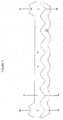
- Figure 6depicts an underside view of the tray of Figure 5 and wherein each projection 16 (in Figure 5 ) is shown as under-trough 16a and likewise each .trough 18 (in Figure 5 ) is shown as under-projection 18a.
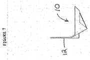
- Figure 7depicts an end view of display tray 10 showing back wall 12.
- Figure 10depicts a perspective view of tray 10 having pot 42 in situ within one trough.
- Proximal end of plant pot 45is the end into which plants will be placed.
- Distal end 47abuts back wall 12.
- Figures 8an isometric view of a corner tray piece 11 showing back wall 12a and end walls 13. Corner tray piece may be used to "wrap" an interlocking tray arrangement around a corner. It is preferred that plant trays 12 abut end walls 13. This is shown more specifically in Figure 11 . Preferably end wall 13 abuts an exposed end of tray 10, collectively forming a projection.
- Figure 9is a view of isometric view of a single pot plant propagation and display tray 11a.
- Such single pieces, in operation and usemay abut one or more long tray pieces (such as tray 10) or one or more corner pieces, such as 11 and aid in flexible design configurations.
- Figure 12illustrates the alignment or abutment of tray pieces of varying length to accommodate a multitude of design options.
- tray 10a long tray piece
- tray 10aa mid-sized piece
- tray 11aa single cup tray piece
- wateringcan be initiated in a preferred form, from the top of the assembly.
- water 46is introduced into a first tray level and will travel along the tray to each trough 18 (troughs shown best in Figures 1 , 2 and 5 ) . Due to the limited space afforded by projections 16, and the space within the trough filled by plant pot 42, water will rise to the level of the projection point of abutment 24 and will "spill over" to the next trough in sequence.
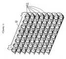
- trays 10are displayed on a wall surface in an assembly 50, as depicted in Figures 13-18 , 20 and 21 .
- This assemblyincludes multiple trays 10 displayed side-by-side in adjacent rows and/or displayed above and below one another in vertical "stacks".
- corner tray pieces 52are also provided. These corner tray pieces allow for uninterrupted green wall around curves and corners and enhance the adaptability of the entire display system.
- Each of trays 10are configured for simple, removable engagement with an adjacent tray 10 using the mating mechanism described above, for vertical stacking.
- Figure 16illustrates a preferred embodiment of multi-tray stacked assembly encircling around end 60 of two joining wall surfaces 61. None of the advantages or functionality of the tray is lost whether the tray is a corner piece, a long tray or a short tray.
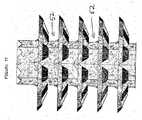
- Figure 17depicts an end view of this same configuration showing primarily end tray pieces 52.
- Figure 18depicts a "slice" of this same multi-tray configuration showing end tray pieces 52 adjacent to plant trays 10.
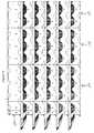
- Figures 20 and 21depict eight vertically stacked and nested trays (10).
- Figure 20is ready to be loaded with pots (one is in place at the lowest tray) whereas in Figure 21 all troughs are loaded with pots 42.
- trayscan be used together on a wall surface.
- an eight trough traycan be positioned above a plurality of two trough trays.
- the combinations for placement vertically and horizontally on a wall surfaceare endless.
- One key advantage of the ability of interchange tray sizesrelates to the differing propagation needs of specific plant varieties.
- water supplycan be specifically tailored to differing trays.
- a water supply line for each specific variety of plantcan be installed to add water only to those trays with specific types of plants. Furthermore, water can then be diverted from those trays back into the drain lines before it cascades down into the plants below them. This allows watering to be controlled within the system on a per species basis. For example, a dry loving plant could be watered only once every two or three weeks, whereas a wet loving plant could be watered on a weekly basis. Wet loving plants would be situated in trays together and likewise dry loving plants would be separated in their own trays.
- Each plantcould reside directly beside, below or above the other and yet have completely different watering schedules that would not conflict with the water requirements of the adjacent plant. This allows for a much higher level of plant health control and for the intermixing of unlike species together on the wall to achieve specific design or air quality goals.
- each trayincludes an irrigation line.
- each trayincludes a drainage line for egress of water to a second tray below said tray when in aligned arrangement on a wall surface.
- the tray of the present inventionis attached to a wall surface which is part of either a wall cabinet or built-in unit.
- Trays 10 when not in use and for transportation efficienciesare fully nestable to facilitate ease of shipping and to decrease space requirements in shipping containers.
- Components of tray 10are constructed from suitable materials such as extruded plastics, aluminium, stainless steel, or other materials known in the art.
- Extruded plasticsmay further include one or more of additional additives for example, anti-microbials, antioxidants, antistatic agents, blowing agents, fragrances, biodegradable plasticizers, biostabilizers, external lubricants, fillers, extenders, flame retardants, heat stabilizers, impact modifiers, internal lubricants, light stabilizers, pigments, process aids, reinforcers, rubberizers, and any other additives known in the art.
- the extruded plasticsinclude a rubberizer to enable the plastic to maintain flexibility at cooler temperatures.
- the plastics materialsmay include one or more of polypropylene (PP), polyethylene (PE), polyethylene terephthalate (PET), polystyrene (PS), polyvinylchloride (PVC), polyfluroethylene (PFE), polyurethane (PU), polytetrafluoroethylene (PTFE) and polycarbonate.
- suitable rubberizersinclude UV additives.
- At least one sensoris integrated into the tray 10.
- a sensormay be used to detect at least one parameter in the plant growth environment, for example a physico-chemical condition in the growth environment or media within or near the plant pots.
- this sensordetects, compiles, and analyzes data related to the at least one parameter in the plant growth environment.
- the sensormay, for example, include a temperature sensor or a moisture sensor (within the plant pots) or may include pH sensors and/or nutrient sensors selected for monitoring the media or growing environment.
- the planter wall of traysfurther comprises a utility control system for the provision of at least one utility to the trays.
- the utilityis selected from the group consisting of a heating line, electrical wire, a misting water supply line and combinations thereof.
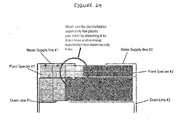
- Figure 24illustrates differential water control, as between two water supply lines (#1 and #2) having respective drain lines (#1 and #2)and wherein plant species #1 and plant species #2 have differing watering requirements.
Landscapes
- Life Sciences & Earth Sciences (AREA)
- Environmental Sciences (AREA)
- Cultivation Receptacles Or Flower-Pots, Or Pots For Seedlings (AREA)
Description
- The present invention relates to green walls and in particular to plant propagation and display trays and assemblies.
- In recent years the push for both industry and individuals to be more environmentally aware has led to many green initiatives including green roofs and green walls. Currently in cities such as Chicago, over 2.5 million square feet of the downtown core roof space are covered with hardy green roof plants. Green walls and roofs provide savings on insulation and place less load bearing strain on a building. In addition, plants being carbon producers, the use of green walls and roofs are thought to decrease greenhouse gas emissions. Further still, these green walls and roofs act to offset the newly identified 'urban heat island effect' where the heat-absorbing surfaces in a city raise its temperature to as much as 8 degrees higher than that of the surrounding countryside.
- However, green walls currently known in the art have their own unique set of challenges associated with them, the first being gravity. In conventional methods of greening buildings, it is well known to cover wall surfaces with ivy or to plant trees into the soil deposited on wall surfaces. One of the early green walls disclosed in
U.S. Pat. No. 5,257,476 requires preparation of a plurality of bags loaded with soil, piling the bags against a wall surface of a building and inserting trees' roots between the piled bags so as to plant trees, erecting a lattice fence outside the stacked bags, and promoting the plants growth and clinging to the lattice. - In more recent years, seeding and planting panels have been used for greening surfaces of permanent constructions such as buildings, retaining walls, and the like. These seeding and planting panels generally include a panel frame, and a seeding and planting mat or block contained within the frame. In general, these types of panel frames are fixedly secured to surfaces of existing constructions such as building wall surfaces, roofs or retaining walls, and are integrally incorporated into the constructions so as to be permanent structural elements thereof. It is very cumbersome to exchange these panels as they are not easily disengaged from their supports and removed. In addition, as the backside faces of the panels are concealed, general maintenance work is very difficult.
- By way of example, the following are offered as known types of green wall technologies:
DocumentUS-A-2011016784 discloses a plant propagation and display tray, which is capable of interlocking alignement with at least one other tray and which is capable of receiving and holding at least one plant pot, comprising a back wall and a bottom ledge towardly projecting from said back wall. - Japanese Pat. Appl. Pub. No.
2004-254565
" The greening panel 100 is composed of apanel frame 10 installed on the vertical plane side with a support frame and forming a work opening enabling planting at least a pot seedling at least on a front face, a bag-like mat material 20A arranged and supported just in the inside of thepanel frame 10, enabling cut open work from the outside of the work opening and having water absorption properties and restoring force, and avegetation base material 30 for raising a vegetation plant P, filled in the inside of the bag-like mat material 20A or a three-dimensional netlike mat filled with the base material. A support frame is composed of many metallic linear support pipes, pipe-connecting members connecting the ends of the pipes with each other and hanging tools connected to part of thepanel frame 10 and hanging thepanel frame 10 on the support pipes. "(Abstract) - Japanese Pat. Appl. Pub. No.
2003-155714
" Thegreening panel device 1 is provided with upper andlower greening panels 3 and 5, right and leftvertical members panel fixtures 13 for attaching eachgreening panel 3 and 5 in parallel across the right and leftvertical members greening panel 3 and 5 so that a lower part protrudes forward than an upper part, and water receptors 15 guiding received water to the lower greening panel are detachably provided on lower faces of thepanel fixtures 13. "(Abstract) - Japanese Pat. Appl. Pub. No.
2004-248550
"Thisdevice 10 for greening a wall surface has a plurality ofplanting units 12 arranged along anexternal wall surface 4 of abuilding 2 and planted withplants 14. Each of theplanting units 12 is hung sequentially from the top through hangingmembers 16 to be connected with each other. Theplanting unit 12 on the top is fixed to a parapet 7 on a rooftop 6 of thebuilding 2 with awire 18. The rooftop 6 of thebuilding 2 is set with a lifting and loweringdevice 30 for lifting and lowering theplanting units 12 through drawing and rolling thewire 18. " (Abstract) US Patent 5,579,603 describes:
"A plant-growing method for greening upright or slant wall surface is disclosed. A flexible bag is first prepared including a plurality of compartments sequentially juxtaposed in the direction of the overall length of the bag. The compartments are each provided with a plurality of openings communicating with the exterior. Soil is then loaded through the openings into the compartments with the bag being horizontally laid. Afterwards, trees are planted through the openings into the compartments. Thereupon, the bag which has been planted with the trees is suspended along the wall surface in the direction of the overall length of the bag while allowing trunks of the trees to be exposed through the openings. Water is thereafter supplied into the compartments of the bag to promote the growth of the trees. "(Abstract)- United States Pat. Appl. Pub. No.
2007/0199241A1 refers to:
"A light self-supporting vegetated wall includes globally prismatic boxes, designed to be juxtaposed and/or stacked, the adjacent boxes being assembled together. Each box includes latticed or meshed surfaces, lined internally with a web, and filled with a cultivating substrate, such as humus. A network of water pipes and a network of air vents may be incorporated in the thickness of the structure, these networks passing through the parting lines between the boxes. The structure is designed for urban enhancement, as well as for producing noise screens, partition walls, hoardings and the like. "(Abstract) US Patent 4,658,541 describes interlocking semi-circular planters wherein plants are individually contained in each discrete planter and wherein the back walls are formed with teeth and notches for interconnection with other semi-circular planters on a wall.US Patent 7,536,829 describes a planting base for use on walls and roofs comprising a holding cover having an open window divided by a holding cross-piece and a tray for supporting the holding cover and for receiving culture soil with which the holding cover is filled.- There remains the need for a simple green wall system which would allow easy installation and removal and easy replacement of plants, while at the same time providing optimal conditions for plant growth. It is an object of the present invention to obviate or mitigate the above-noted disadvantages.
- The present invention provides a plant propagation and display tray, which is capable of interlocking alignment with at least one other tray and which is capable of receiving and holding at least one plant pot, comprises a back wall and a bottom ledge forwardly projecting from said back wall; said ledge being inclined towards the back wall and comprising a plurality of alternating projections and troughs, each of said troughs inclining towards a trough point of abutment with the back wall and being of a conformation to securably hold one plant pot such that an open proximal end of the plant pot is exposed to view and a distal end of the plant pot is adjacent to the back wall; each of said projections having an upper surface which inclines towards a projection point of abutment with the back wall, wherein the projection point of abutment is higher than the trough point of abutment with the back wall; wherein said tray is capable of being attached to a wall surface.
- The present invention further provides a planter wall formed of a plurality of interlocking trays as described above, one above another, and/or one beside another and attached to a wall surface.
- The tray of the present invention offers a multitude of advantages not found in any prior green wall system. In particular, the provision of the alternating troughs and projections on the ledge, and the inclinations of each "backwards" i.e. to the direction of the back wall controls water delivery to the plants (in the pots), once such plants are in place within the troughs. In this unique arrangement, the body of the projections essentially takes up space where water would otherwise pool. The base of a plant pot, once in place, is thereby only exposed to enough water to allow wicking, while avoiding soaking. This reduces or eliminates problems such as rot. Furthermore, many plant varieties do not thrive being watered from the top.
- The design and conformation of the tray in accordance with the present invention allows interlocking placement of a plurality of trays, one above the other, or one beside another and all attached to a wall surface thereby forming, once plant pots are inserted, a "green wall". By way of water drainage from an upper level tray to one below, watering may be accomplished by the use of gravity.
- The system of the present invention is highly adaptable to a wide variety of green wall installations.
- These and other objects and advantages of the present invention will become more apparent to those skilled in the art upon reviewing the description of the preferred embodiments of the invention, in conjunction with the figures and examples.
- The following figures set forth embodiments of the invention in which like reference numerals denote like parts. Embodiments of the invention are illustrated by way of example and not by way of limitation in the accompanying figures and description of the preferred embodiments which follow.
Figure 1 is an perspective view of a plant propagation and display tray according to one embodiment;Figure 2 is a further perspective view of the plant propagation and display tray ofFigure 1 ;Figure 3 is a front view of a plant propagation and display tray;Figure 4 is a back plan view of a plant propagation and display panel;Figure 5 is a top plan view of a plant propagation and display tray;Figure 6 is a bottom plan view of a plant propagation and display tray;Figure 7 is an end view of a plant propagation and display tray;Figure 8 is an isometric view of a corner tray piece;Figure 9 is a view of isometric view of a single pot plant propagation and display tray;Figure 10 is a perspective view of a plant propagation and display tray including one plant pot;Figure 11 is a perspective view of a plant propagation and display tray including one plant pot and a corner tray piece;Figure 12 is a front plan view of three adjacent plant propagation and display trays, of differing length;Figure 13 is a front plan view of eight plant propagation and display trays in stacking arrangement;Figure 14 is a back plan view of eight plant propagation and display trays in stacking arrangement;Figure 15 is a perspective view of a plurality of plant propagation and display trays, each adjacent to a respective corner tray piece;Figure 16 is a perspective view, from the top, of a plurality of plant propagation and display trays each adjacent to a respective corner tray piece, with each corner tray piece then being adjacent to a respective plant propagation and display tray on an opposite side of a support structure;Figure 17 is a perspective view, from the side of five corner tray pieces, each abutting a respective plant propagation and display tray on both sides of a support structure;Figure 18 is a top plan view of a plurality of two-pot plant propagation and display trays, with one being adjacent to a corner tray piece, which is adjacent to a further two-pot plant propagation and display tray on an opposite side of a support structure;Figure 19 is a depiction of various plant pot sizes which may be used in the tray of the present invention;Figure 20 is a perspective view of the eight plant propagation and display trays in stacking arrangement, ofFigure 13 ;Figure 21 is a perspective view of the eight plant propagation and display trays in stacking arrangement, ofFigure 20 , but each trough containing a plant pot;Figure 22 is a cross-sectional depiction of the irrigation/watering system in accordance with the present invention;Figure 23 is cross-sectional depiction of the irrigation/watering system ofFigure 22 , without the plant potsin situ; andFigure 24 is a schematic for a multi-tray assembly showing multiple water supply lines.- A detailed description of one or more embodiments of the invention is provided below along with accompanying figures that illustrate the principles of the invention. As such this detailed description illustrates the invention by way of example and not by way of limitation. The description will clearly enable one skilled in the art to make and use the invention, and describes several embodiments, adaptations, variations and alternatives and uses of the invention, including what we presently believe is the best mode for carrying out the invention. It is to be clearly understood that routine variations and adaptations can be made to the invention as described, and such variations and adaptations squarely fall within the spirit and scope of the invention.
- In other words, the invention is described in connection with such embodiments, but the invention is not limited to any embodiment. The scope of the invention is limited only by the claims and the invention encompasses numerous alternatives, modifications and equivalents. Numerous specific details are set forth in the following description in order to provide a thorough understanding of the invention. These details are provided for the purpose of example and the invention may be practiced according to the claims without some or all of these specific details. For the purpose of clarity, technical material that is known in the technical fields related to the invention has not been described in detail so that the invention is not unnecessarily obscured. Similar reference characters denote similar elements throughout various views depicted in the figures.
- This description of preferred embodiments is to be read in connection with the accompanying drawings, which are part of the entire written description of this invention. In the description, corresponding reference numbers are used throughout to identify the same or functionally similar elements. If and when used herein relative terms such as "horizontal," "vertical," "up," "down," "top" and "bottom" "front", "back" as well as derivatives thereof (e.g., "horizontally," "downwardly," "upwardly," etc...) should be construed to refer to the orientation as then described or as shown in the drawing figure under discussion. These relative terms are for convenience of description and are not intended to require a particular orientationunless specifically stated as such. Terms including "inwardly" versus "outwardly," "longitudinal" versus "lateral" , "adjacent" and the like (if used) are to be interpreted relative to one another or relative to an axis of elongation, or an axis or center of rotation, as appropriate. Terms concerning attachments, coupling and the like, such as "connected" and "interconnected," refer to a relationship wherein structures are secured or attached to one another either directly or indirectly through intervening structures, as well as both movable or rigid attachments or relationships, unless expressly described otherwise.
- In the present disclosure and claims , the word "comprising" and its derivatives including "comprises" and "comprise" include each of the stated integers butdoes not exclude the inclusion of one or more further integers or elements. The terms cords and cording may be used interchangeably.
- The present invention provides, in one aspect, a plant propagation and display tray which provides several key advantages including the provision, by way of a unique configuration of troughs and projections, of a zone for placement of plant pots around which water does not unnecessarily pool.
- Referring to
Figures 1-3 , an embodiment of a plant propagation anddisplay tray 10 is generally shown. The plant propagation anddisplay tray 10 comprises aback wall 12 and abottom ledge 14 forwardly projecting from said back wall. As provided herein, the "back wall" refers to the moiety of the tray that, in use, will abut the structure against which the planter wall is to be placed.Ledge 14 is inclined towards the back wall and comprises a plurality of alternating projections, 16 andtroughs 18, with each oftroughs 18 inclining towards a trough point of abutment, 20 with the back wall.Troughs 18 are of a conformation to securably hold one plant pot, (shown in 10, 11, 12 and 13, among other figures) such that an open proximal end of the plant pot is exposed to view and a distal end of the plant pot is adjacent to the back wall. Each ofprojections 16 have an upper surface 22 which inclines towards a projection point ofabutment 24 with the back wall, wherein the projection point ofabutment 24 is generally higher than the trough point ofabutment 20 with the back wall. The purpose for this design will be described further below. - Back
wall 12 comprises a substantially flatupper portion 26 and a lower portion, adjacent the ledge, which is thicker than the upper portion and which is defined by a plurality of substantially V-shaped depressions, 28, each of which points towards a trough on the ledge. The reverse side ofback wall 12 is depicted inFigure 4 which shows a substantially flat surface for alignment with a wall surface, when the tray is in use. - It has been found that the inclusion of such V-shaped depressions, within this relatively thicker part of the back wall and "aligned with" or pointing towards its corresponding ledge trough affords enormous advantages in increasing the overall strength and weight-bearing ability of the tray. Without this feature, and for trays with more than a few plant-pots inserted therein, there is a risk of sag and the potential of the tray not being able to support the weight of multiple pots, growing media and plants. It is fully contemplated within the scope of the present invention that trays may be of varying lengths and comprise differing numbers of plant-pot receiving troughs. For example, the tray in
Figure 1 depicts 8 plant-pot receiving troughs. InFigure 12 , trays are depicted with 8, 3 and 1 plant-pot receiving troughs. Female alignment member 30 is shown inFigures 1-4 , integrally formed as part ofback wall 12. Similarlymale alignment member 32 is best shown inFigure 4 . In operation and as best shown inFigure 14 , when a plurality of trays provided generally as 34, are stacked for use on a wall surface, each such tray is aligned in the correct position, relative to the trays above and below, by use of the male and female alignment members. More specifically, fortray 36,female alignment member 30 is engaged bymale alignment member 32 oftray 38. This alignment obviates the need for any other measuring means to ensure accurate vertical stacking of more than one tray.Holes 40 are provided on each tray for pass through by screws, nails or other means of securing the tray to a wall surface.Figure 5 is useful to show the alternating arrangement ofprojections 16 andtroughs 18 and the preferred shape and inclination of those features towardsback wall 12.Troughs 18 incline to trough points ofabutment 20 and are of a conformation which is acceptable to receive and securably hold a desired size of plant pot 42 (Figures 11 and12 , among other figures, show one plant pot in place). The distal end ofplant pot 42, when in place withintrough 18, sits adjacent to trough point ofabutment 20. The entirety ofplant pot 42 is additionally held in place by the conformation ofprojections 16. InFigure 5 , the entire structure of each projection is clearly shown. In a preferred form, each projection comprising four sides (43a, 43b, 43c and 43d) meeting atapex 44. Side 43c inclines towards and meets backwall 12 at projection point ofabutment 24. The importance of the configuration ofprojection 16 andtrough 18 becomes apparent in respect to water distribution and pooling withintray 10 and draining fromtray 10. An understanding of this is best achieved with reference toFigures 5 ,22 and23 .Figure 6 depicts an underside view of the tray ofFigure 5 and wherein each projection 16 (inFigure 5 ) is shown as under-trough 16a and likewise each .trough 18 (inFigure 5 ) is shown as under-projection 18a.Figure 7 depicts an end view ofdisplay tray 10 showingback wall 12.Figure 10 depicts a perspective view oftray 10 havingpot 42 in situ within one trough. Proximal end ofplant pot 45 is the end into which plants will be placed.Distal end 47 abuts backwall 12.Figures 8 an isometric view of acorner tray piece 11 showingback wall 12a and endwalls 13. Corner tray piece may be used to "wrap" an interlocking tray arrangement around a corner. It is preferred thatplant trays 12abut end walls 13. This is shown more specifically inFigure 11 . Preferably endwall 13 abuts an exposed end oftray 10, collectively forming a projection.Figure 9 is a view of isometric view of a single pot plant propagation and display tray 11a. Such single pieces, in operation and use may abut one or more long tray pieces (such as tray 10) or one or more corner pieces, such as 11 and aid in flexible design configurations.Figure 12 illustrates the alignment or abutment of tray pieces of varying length to accommodate a multitude of design options. In this case, tray 10 (a long tray piece) abutstray 10a (a mid-sized piece) which in turn abuts tray 11a (a single cup tray piece). Regardless of size (long, medium, single, or in fact other length), the principle of the invention and alignment of troughs and projections is applied.- When trays are installed, one above another on a wall surface, watering can be initiated in a preferred form, from the top of the assembly. As shown in
Figures 22 (pots) and 23 (no pots),water 46 is introduced into a first tray level and will travel along the tray to each trough 18 (troughs shown best inFigures 1 ,2 and5 ) . Due to the limited space afforded byprojections 16, and the space within the trough filled byplant pot 42, water will rise to the level of the projection point ofabutment 24 and will "spill over" to the next trough in sequence. By virtue of this unique configuration and design, space is afforded for only a minimal amount of water near the distal end of each plant pot, enough for wicking and not for soaking. As such, unneeded water quickly moves along the tray, over projection sides 43c and will egress from a tray atdrain 48. When trays are installed, one above another, drain 48 will be the conduit for water supply to the tray level below, as shown clearly inFigure 22 . - In a further alternative embodiment,
trays 10 are displayed on a wall surface in an assembly 50, as depicted inFigures 13-18 ,20 and 21 . This assembly includesmultiple trays 10 displayed side-by-side in adjacent rows and/or displayed above and below one another in vertical "stacks". Also provided are corner tray pieces 52 (as shown best inFigures 16 and18 ) for wrapping trays around a non-flat wall surface. These corner tray pieces allow for uninterrupted green wall around curves and corners and enhance the adaptability of the entire display system. - Each of
trays 10 are configured for simple, removable engagement with anadjacent tray 10 using the mating mechanism described above, for vertical stacking. Figure 16 illustrates a preferred embodiment of multi-tray stacked assembly encircling around end 60 of two joining wall surfaces 61. None of the advantages or functionality of the tray is lost whether the tray is a corner piece, a long tray or a short tray.Figure 17 depicts an end view of this same configuration showing primarily endtray pieces 52.Figure 18 depicts a "slice" of this same multi-tray configuration showingend tray pieces 52 adjacent to planttrays 10.Figures 20 and21 depict eight vertically stacked and nested trays (10).Figure 20 is ready to be loaded with pots (one is in place at the lowest tray) whereas inFigure 21 all troughs are loaded withpots 42.- It is to be understood that different sized trays can be used together on a wall surface. For example, an eight trough tray can be positioned above a plurality of two trough trays. The combinations for placement vertically and horizontally on a wall surface are endless. One key advantage of the ability of interchange tray sizes relates to the differing propagation needs of specific plant varieties.
- It is to be understood that plant pots of varying sizes can be "loaded" into the troughs of the plant trays.
Figure 19 illustrates various preferred pot diameters which range from 4" to 1 foot. This range is not intended to be limiting. - In one embodiment of the present invention, water supply can be specifically tailored to differing trays. A water supply line for each specific variety of plant can be installed to add water only to those trays with specific types of plants. Furthermore, water can then be diverted from those trays back into the drain lines before it cascades down into the plants below them. This allows watering to be controlled within the system on a per species basis. For example, a dry loving plant could be watered only once every two or three weeks, whereas a wet loving plant could be watered on a weekly basis. Wet loving plants would be situated in trays together and likewise dry loving plants would be separated in their own trays. Each plant could reside directly beside, below or above the other and yet have completely different watering schedules that would not conflict with the water requirements of the adjacent plant. This allows for a much higher level of plant health control and for the intermixing of unlike species together on the wall to achieve specific design or air quality goals.
- In a preferred embodiment, each tray includes an irrigation line. In a further preferred embodiment, each tray includes a drainage line for egress of water to a second tray below said tray when in aligned arrangement on a wall surface.
- In a preferred embodiment, the tray of the present invention is attached to a wall surface which is part of either a wall cabinet or built-in unit.
Trays 10 when not in use and for transportation efficiencies are fully nestable to facilitate ease of shipping and to decrease space requirements in shipping containers.- Components of
tray 10 are constructed from suitable materials such as extruded plastics, aluminium, stainless steel, or other materials known in the art. Extruded plastics may further include one or more of additional additives for example, anti-microbials, antioxidants, antistatic agents, blowing agents, fragrances, biodegradable plasticizers, biostabilizers, external lubricants, fillers, extenders, flame retardants, heat stabilizers, impact modifiers, internal lubricants, light stabilizers, pigments, process aids, reinforcers, rubberizers, and any other additives known in the art. In one embodiment the extruded plastics include a rubberizer to enable the plastic to maintain flexibility at cooler temperatures. The plastics materials may include one or more of polypropylene (PP), polyethylene (PE), polyethylene terephthalate (PET), polystyrene (PS), polyvinylchloride (PVC), polyfluroethylene (PFE), polyurethane (PU), polytetrafluoroethylene (PTFE) and polycarbonate. Examples of suitable rubberizers include UV additives. - In one embodiment, at least one sensor is integrated into the
tray 10. For example, a sensor may be used to detect at least one parameter in the plant growth environment, for example a physico-chemical condition in the growth environment or media within or near the plant pots. Preferably, this sensor detects, compiles, and analyzes data related to the at least one parameter in the plant growth environment. The sensor may, for example, include a temperature sensor or a moisture sensor (within the plant pots) or may include pH sensors and/or nutrient sensors selected for monitoring the media or growing environment. - In a preferred embodiment, the planter wall of trays further comprises a utility control system for the provision of at least one utility to the trays. The utility is selected from the group consisting of a heating line, electrical wire, a misting water supply line and combinations thereof.
- In a preferred form,
Figure 24 illustrates differential water control, as between two water supply lines (#1 and #2) having respective drain lines (#1 and #2)and whereinplant species # 1 andplant species # 2 have differing watering requirements. By manipulating placement of the trays, applying such secondary water supply lines, the planting arrangement therein and via drain line diversions, it is possible to control water supply and volume to "sectors" of the tray stacks. - While embodiments of the present invention have been shown and described herein, it will be obvious to those skilled in the art that such embodiments are provided by way of example only. Numerous variations, changes, and substitutions will be obvious to those skilled in the art without departing from the invention. It should be understood that various alternatives to the embodiments of the invention described herein may be employed in practicing the invention. It is intended that the following claims define the scope of the invention and that methods and structures within the scope of these claims and their equivalents be covered thereby.
- While the forms of elongate members, devices and the system described herein constitute preferred embodiments of this invention, it is to be understood that the invention is not limited to these precise forms. As will be apparent to those skilled in the art, the various embodiments described above can be combined to provide further embodiments. Aspects of the present device and system, and methods of use (including specific components thereof) can be modified, if necessary, to best employ the systems, methods, nodes and components and concepts of the invention. These aspects are considered fully within the scope of the invention as claimed. .For example, the various methods described above may omit some acts, include other acts, and/or execute acts in a different order than set out in the illustrated embodiments. Further, in the methods taught herein, the various acts may be performed in a different order than that illustrated and described. Additionally, the methods can omit some acts, and/or employ additional acts.
- These and other changes can be made to the present systems, methods and articles in light of the above description. In general, in the following claims, the terms used should not be construed to limit the invention to the specific embodiments disclosed in the specification and the claims, but should be construed to include all possible embodiments along with the full scope of equivalents to which such claims are entitled. Accordingly, the invention is not limited by the disclosure, but instead its scope is to be determined entirely by the following claims.
Claims (15)
- A plant propagation and display tray (10), which is capable of interlocking alignment with at least one other tray (10) and which is capable of receiving and holding at least one plant pot (42), comprises:a back wall (12) and a bottom ledge (14) forwardly projecting from said back wall;characterised in that,said ledge (14) being inclined towards the back wall (12) and comprising a plurality of alternating projections (16) and troughs (18), each of said troughs (18) inclining towards a trough point of abutment (20) with the back wall (12) and being of a conformation to securably hold one plant pot (42) such that an open proximal end of the plant pot is exposed to view and a distal end of the plant pot (42) is adjacent to the back wall (12);each of said projections (16) having an upper surface which inclines towards a projection point of abutment (24) with the back wall (12), wherein the projection point of abutment (24) is higher than the trough point of abutment (20) with the back wall (12);wherein said tray (10) is capable of being attached to a wall surface.
- The tray (10) of claim 1 wherein the ledge (14) comprises walls at each end.
- The tray (10) of claim 1 or 2 wherein the back wall (12), on one side, comprises a substantially flat upper portion (26) and a lower portion, adjacent the ledge, which is thicker than the upper portion and which is defined by a plurality of substantially V-shaped depressions (28), each of which points towards a trough (18) on the ledge (14), and wherein the back wall (12), on the other side, is defined by a flat surface for alignment with a wall surface, when the tray (10) is in use.
- The tray (10) of claim 1, 2 or 3, which includes an irrigation line.
- The tray (10) of any of the claims 1-4, which includes a drainage line for egress of water to a second tray (10) below said tray when in aligned arrangement on a wall surface.
- The tray (10) of any of the claims 1-5 which is shaped for nestable stacking with a plurality of plant trays.
- The tray (10) of claim 1 (tray 1) which comprises, on an upper edge of the back wall, a means for spaceable interconnection with an opposite means of interconnection on a lower edge of a back wall (12) of a second tray (tray 2) which may be placed above said tray (tray 1) on a wall surface.
- The tray (10) of claim 7 (tray 1) wherein the means for spaceable interconnection includes a female member (30) on the upper edge of the back wall (12) and a male member (32) on the lower edge of the back wall (12) of the second tray (tray 2) wherein the interconnection of the female member of tray 1 and the male member of the second tray (tray 2) allow exact alignment of the trays on the wall and defme a desired spacing between the trays.
- The tray (10) of any of the preceding claims, which comprises a mounting device (40) for coupling said tray to a wall surface.
- The tray (10) of any of the preceding claims, wherein the wall surface is part of a wall cabinet or a part of a built-in wall unit.
- A planter wall formed of a plurality of interlocking trays (10) as described in any of the preceding claims, one above another, and attached to a wall surface.
- The planter wall of claim 11 which forms part of a wall cabinet.
- The planter wall of claim 11 which forms part of a built-in wall unit.
- The planter wall of claim 11, 12 or 13, further comprising a utility control system for the provision of at least one utility to the trays (10).
- The planter wall of any of the claims 11-14, further comprising at least one utility selected from the group consisting of a heating line, electrical wire, a misting water supply line and combinations thereof.
Applications Claiming Priority (1)
| Application Number | Priority Date | Filing Date | Title |
|---|---|---|---|
| US201161438150P | 2011-01-31 | 2011-01-31 |
Publications (2)
| Publication Number | Publication Date |
|---|---|
| EP2481279A1 EP2481279A1 (en) | 2012-08-01 |
| EP2481279B1true EP2481279B1 (en) | 2013-11-13 |
Family
ID=45558609
Family Applications (1)
| Application Number | Title | Priority Date | Filing Date |
|---|---|---|---|
| EP20120153326ActiveEP2481279B1 (en) | 2011-01-31 | 2012-01-31 | Interlocking plant propagation and display tray and method of use and assembly |
Country Status (3)
| Country | Link |
|---|---|
| US (2) | US9004298B2 (en) |
| EP (1) | EP2481279B1 (en) |
| ES (1) | ES2446615T3 (en) |
Cited By (1)
| Publication number | Priority date | Publication date | Assignee | Title |
|---|---|---|---|---|
| US10694684B2 (en) | 2011-07-22 | 2020-06-30 | Naturvention Oy | Apparatus for the growing of plants and a growing device |
Families Citing this family (33)
| Publication number | Priority date | Publication date | Assignee | Title |
|---|---|---|---|---|
| CA2805851C (en) | 2009-10-08 | 2017-03-07 | Adam K. Fontecchio | Led lighting system |
| US20130025196A1 (en)* | 2011-07-29 | 2013-01-31 | Steven Decker | System for displaying plants |
| EP2891019B1 (en) | 2012-08-28 | 2020-03-04 | Delos Living, LLC | Systems and methods for enhancing wellness associated with habitable environments |
| USD719055S1 (en) | 2013-07-10 | 2014-12-09 | Fork Farms LLC | Modular plant growth apparatus |
| WO2015125057A1 (en)* | 2014-02-21 | 2015-08-27 | Satish Madhukar Gokhale | Plant tray for growing plants |
| EP3754588B1 (en) | 2014-02-28 | 2023-08-16 | Delos Living LLC | Systems, methods, and articles for enhancing wellness associated with habitable environments |
| EP3245631A4 (en) | 2015-01-13 | 2018-06-27 | Delos Living, LLC | Systems, methods and articles for monitoring and enhancing human wellness |
| CA2962149C (en)* | 2015-03-13 | 2019-11-26 | Conwed Plastics Acquisition Company V Llc, Dba Filtrexx International | System and method for covering portions of an existing structure with plants |
| WO2016191596A1 (en) | 2015-05-26 | 2016-12-01 | Delos Living Llc | Green wall modular system |
| USD761598S1 (en) | 2015-05-26 | 2016-07-19 | Delos Living Llc | Green wall frame |
| US20180014471A1 (en)* | 2016-07-14 | 2018-01-18 | Mjnn Llc | Vertical growth tower and module for an environmentally controlled vertical farming system |
| EP3504942A4 (en) | 2016-08-24 | 2020-07-15 | Delos Living LLC | SYSTEMS, METHODS AND ARTICLES FOR IMPROVING WELL-BEING IN LIVABLE ENVIRONMENTS |
| US11172621B2 (en)* | 2017-03-15 | 2021-11-16 | George Addison Irwin | Modular vertical agriculture assembly to support vegetative growth in the vertical plane |
| US20180295800A1 (en) | 2017-04-18 | 2018-10-18 | Phidro Llc | Vertically oriented modular aerohydroponic systems and methods of planting and horticulture |
| WO2019003201A2 (en) | 2017-06-30 | 2019-01-03 | Pipp Mobile Storage Systems, Inc. | Grow rack system including trays with integrated drainage |
| WO2019046580A1 (en) | 2017-08-30 | 2019-03-07 | Delos Living Llc | Systems, methods and articles for assessing and/or improving health and well-being |
| IT201700118846A1 (en)* | 2017-10-20 | 2019-04-20 | Travaglini S P A | TRAY FOR CULTIVATION OF AGRICULTURAL PRODUCTS, PARTICULARLY FOR VERTICAL FARM |
| US11997963B1 (en) | 2017-11-14 | 2024-06-04 | Pipp Mobile Storage Systems, Inc. | Trays for plant cultivation |
| US11116148B1 (en) | 2017-11-14 | 2021-09-14 | Pipp Mobile Storage Systems, Inc. | Trays for plant cultivation |
| US10383464B2 (en)* | 2017-11-17 | 2019-08-20 | Les Industries Rondi Inc. | Flower pots support modular system |
| US10842300B2 (en)* | 2018-04-19 | 2020-11-24 | Carl Reid | Mountable container |
| US11649977B2 (en) | 2018-09-14 | 2023-05-16 | Delos Living Llc | Systems and methods for air remediation |
| US11844163B2 (en) | 2019-02-26 | 2023-12-12 | Delos Living Llc | Method and apparatus for lighting in an office environment |
| WO2020198183A1 (en) | 2019-03-25 | 2020-10-01 | Delos Living Llc | Systems and methods for acoustic monitoring |
| US11206767B2 (en)* | 2019-03-28 | 2021-12-28 | GSKY Plant Systems, Inc. | Modular planting tray and vertical wall planting system |
| USD896122S1 (en)* | 2019-03-28 | 2020-09-15 | GSKY Plant Systems, Inc. | Planting tray |
| US12253249B2 (en) | 2019-08-01 | 2025-03-18 | Schuyler David Milton | Device and method for growing crops with non-fibrous and non-consumable media |
| WO2021071813A1 (en)* | 2019-10-07 | 2021-04-15 | Caraway Home, Inc. | Cookware lid holder |
| US11707027B2 (en) | 2019-12-02 | 2023-07-25 | Fork Farms Holdings, Llc | Hydroponic grow assembly |
| JP7594410B2 (en) | 2020-10-30 | 2024-12-04 | 信明 三木 | Hydroponic Cultivation Equipment |
| US11252875B1 (en) | 2021-04-01 | 2022-02-22 | Andromeda District Holdings Corp. | Paneling system for mounting planters on a wall or roof structure |
| US12251014B2 (en) | 2022-11-11 | 2025-03-18 | Pipp Mobile Storage Systems, Inc. | Rack systems |
| WO2025171493A1 (en)* | 2024-02-15 | 2025-08-21 | Tevagrow Inc. | Modular vertical horticulture system and apparatus |
Family Cites Families (26)
| Publication number | Priority date | Publication date | Assignee | Title |
|---|---|---|---|---|
| US2915162A (en)* | 1959-06-04 | 1959-12-01 | Donald E Umstead | Bin dispenser |
| US3207321A (en)* | 1964-02-20 | 1965-09-21 | James E Joyce | Bins |
| US3422961A (en)* | 1966-12-12 | 1969-01-21 | S & M Co | Cabinet for cylindrical objects |
| US4131203A (en)* | 1977-01-13 | 1978-12-26 | Aladdin Industries, Incorporated | Wall mounted modular units |
| US4294363A (en)* | 1979-12-17 | 1981-10-13 | The Kent Corporation | Merchandise shelving display |
| US4295296A (en)* | 1980-01-14 | 1981-10-20 | Kinghorn Michael H | Vertical garden |
| GB2087701A (en)* | 1980-06-16 | 1982-06-03 | Saunders Nicholas James Carr | Plant pots |
| DE3420037A1 (en)* | 1984-05-29 | 1985-12-05 | Georg 2400 Lübeck Dose | Add-on shaped elements for planting greenery |
| US5031780A (en)* | 1987-07-09 | 1991-07-16 | Innovative Display Associates, Inc. | Slot-wall shelf for video cassette display |
| US4887388A (en)* | 1988-10-19 | 1989-12-19 | Waltel Jr Joseph | Irrigation system for commercial plant cultivation |
| WO1990004326A1 (en)* | 1988-10-20 | 1990-05-03 | Mielke Horst Guenter | A sales aid for pot plants |
| US4953719A (en)* | 1989-10-03 | 1990-09-04 | The Mead Corporation | Article organizer display unit |
| US5595310A (en)* | 1994-10-28 | 1997-01-21 | The Mead Corporation | Display device having article guide means for encouraging stock rotation |
| US5826375A (en)* | 1996-06-07 | 1998-10-27 | Black; Alan | Modular planter system |
| US6253898B1 (en)* | 1998-07-02 | 2001-07-03 | O'brien Daniel F. | Equipment loading plank |
| FR2857396B1 (en)* | 2003-07-09 | 2006-06-16 | Francois Tribel | FACADE COATING INTEGRATING A VEGETATION DEVICE |
| US6840008B1 (en)* | 2003-10-09 | 2005-01-11 | Chester C. Bullock | Vertical planting system |
| US20060043038A1 (en)* | 2004-09-01 | 2006-03-02 | Air Innovations, Inc. | Scalloped rack or shelf for floral merchandiser |
| US7627983B1 (en)* | 2004-10-15 | 2009-12-08 | Deutsch-Aboulmahassine Elizabeth | Modular, wall-mounted plant growing system |
| AU2007219705A1 (en)* | 2006-02-28 | 2007-09-07 | Clev-A-Garden Pty Ltd | Plant cultivation apparatus with open channel irrigation system |
| EP1991044A4 (en)* | 2006-03-06 | 2012-08-22 | Elevated Landscape Technologies Inc | Title vertical plant supporting system |
| US20090000189A1 (en)* | 2007-06-27 | 2009-01-01 | Alan Black | Modular planter system |
| US7886482B2 (en)* | 2008-01-22 | 2011-02-15 | Dimaggio Angela | Mobile garden cart |
| TWM367678U (en)* | 2008-12-16 | 2009-11-01 | Ke-Dan Ma | Structure of flower wall |
| US20110016784A1 (en)* | 2009-07-24 | 2011-01-27 | Taber Steve M | Modular Wall Planters |
| WO2011136842A1 (en)* | 2010-04-26 | 2011-11-03 | Baker Richard L | Vertical planter |
- 2012
- 2012-01-31EPEP20120153326patent/EP2481279B1/enactiveActive
- 2012-01-31ESES12153326Tpatent/ES2446615T3/enactiveActive
- 2012-01-31USUS13/362,954patent/US9004298B2/enactiveActive
- 2014
- 2014-12-03USUS14/559,189patent/US9468156B2/enactiveActive
Cited By (1)
| Publication number | Priority date | Publication date | Assignee | Title |
|---|---|---|---|---|
| US10694684B2 (en) | 2011-07-22 | 2020-06-30 | Naturvention Oy | Apparatus for the growing of plants and a growing device |
Also Published As
| Publication number | Publication date |
|---|---|
| US20120298599A1 (en) | 2012-11-29 |
| US9004298B2 (en) | 2015-04-14 |
| US20150102000A1 (en) | 2015-04-16 |
| US9468156B2 (en) | 2016-10-18 |
| EP2481279A1 (en) | 2012-08-01 |
| ES2446615T3 (en) | 2014-03-10 |
Similar Documents
| Publication | Publication Date | Title |
|---|---|---|
| EP2481279B1 (en) | Interlocking plant propagation and display tray and method of use and assembly | |
| US11510375B2 (en) | Vertical hydroponic plant production apparatus | |
| US20230337592A1 (en) | Vertical hydroponic plant production apparatus | |
| US20100095586A1 (en) | Plant propagation and display panel and assembly | |
| CA2966344C (en) | Vertical hydroponic tower array fixture system | |
| US9930841B2 (en) | Vertically oriented collapsible hydroponic plant production apparatus | |
| CN102657068A (en) | Outdoor ecological greening wall and installation method thereof | |
| JP2008253218A (en) | Plant culture apparatus | |
| EP2885963B1 (en) | Vertical garden | |
| KR101806264B1 (en) | A Vegetable Growing High-Bed | |
| JP5368041B2 (en) | Container unit for greening | |
| JP4590408B2 (en) | Equipment for growing plants | |
| CA2766610C (en) | Interlocking plant propagation and display tray and method of use and assembly | |
| KR200386097Y1 (en) | Fabricated Cultivation Box and Landscape Architecture System using The Same | |
| JP7111285B2 (en) | Wild yam cultivator and yam cultivation system | |
| KR101619937B1 (en) | plant factory system arranged inside window | |
| NL2010815C2 (en) | Modular system for arranging plant compositions. | |
| KR102077897B1 (en) | Plant-grown pots that can block radiant heat | |
| WO2009084310A1 (en) | Container unit for greening and greening technique using the container unit | |
| KR101646831B1 (en) | Plant conveyer system in under ground greenhouse | |
| CN213548598U (en) | Novel three-dimensional matrix of strawberry is grown seedlings device | |
| KR101260155B1 (en) | Plant cultivating device for outer wall of a building | |
| JP2002125472A (en) | Plant cultivation equipment | |
| JP2004008177A (en) | Connectable type container and container for mounting |
Legal Events
| Date | Code | Title | Description |
|---|---|---|---|
| PUAI | Public reference made under article 153(3) epc to a published international application that has entered the european phase | Free format text:ORIGINAL CODE: 0009012 | |
| AK | Designated contracting states | Kind code of ref document:A1 Designated state(s):AL AT BE BG CH CY CZ DE DK EE ES FI FR GB GR HR HU IE IS IT LI LT LU LV MC MK MT NL NO PL PT RO RS SE SI SK SM TR | |
| AX | Request for extension of the european patent | Extension state:BA ME | |
| RIN1 | Information on inventor provided before grant (corrected) | Inventor name:SICHELLO, CHAD | |
| 17P | Request for examination filed | Effective date:20130201 | |
| GRAP | Despatch of communication of intention to grant a patent | Free format text:ORIGINAL CODE: EPIDOSNIGR1 | |
| RIC1 | Information provided on ipc code assigned before grant | Ipc:A01G 9/02 20060101AFI20130620BHEP | |
| INTG | Intention to grant announced | Effective date:20130723 | |
| GRAS | Grant fee paid | Free format text:ORIGINAL CODE: EPIDOSNIGR3 | |
| GRAA | (expected) grant | Free format text:ORIGINAL CODE: 0009210 | |
| AK | Designated contracting states | Kind code of ref document:B1 Designated state(s):AL AT BE BG CH CY CZ DE DK EE ES FI FR GB GR HR HU IE IS IT LI LT LU LV MC MK MT NL NO PL PT RO RS SE SI SK SM TR | |
| REG | Reference to a national code | Ref country code:GB Ref legal event code:FG4D | |
| REG | Reference to a national code | Ref country code:CH Ref legal event code:EP | |
| REG | Reference to a national code | Ref country code:AT Ref legal event code:REF Ref document number:640151 Country of ref document:AT Kind code of ref document:T Effective date:20131215 | |
| REG | Reference to a national code | Ref country code:IE Ref legal event code:FG4D | |
| REG | Reference to a national code | Ref country code:DE Ref legal event code:R096 Ref document number:602012000458 Country of ref document:DE Effective date:20140109 | |
| REG | Reference to a national code | Ref country code:ES Ref legal event code:FG2A Ref document number:2446615 Country of ref document:ES Kind code of ref document:T3 Effective date:20140310 | |
| REG | Reference to a national code | Ref country code:NL Ref legal event code:VDEP Effective date:20131113 | |
| RAP2 | Party data changed (patent owner data changed or rights of a patent transferred) | Owner name:GSKY PLANT SYSTEMS INC. | |
| REG | Reference to a national code | Ref country code:AT Ref legal event code:MK05 Ref document number:640151 Country of ref document:AT Kind code of ref document:T Effective date:20131113 | |
| REG | Reference to a national code | Ref country code:LT Ref legal event code:MG4D | |
| PG25 | Lapsed in a contracting state [announced via postgrant information from national office to epo] | Ref country code:IS Free format text:LAPSE BECAUSE OF FAILURE TO SUBMIT A TRANSLATION OF THE DESCRIPTION OR TO PAY THE FEE WITHIN THE PRESCRIBED TIME-LIMIT Effective date:20140313 Ref country code:NO Free format text:LAPSE BECAUSE OF FAILURE TO SUBMIT A TRANSLATION OF THE DESCRIPTION OR TO PAY THE FEE WITHIN THE PRESCRIBED TIME-LIMIT Effective date:20140213 Ref country code:NL Free format text:LAPSE BECAUSE OF FAILURE TO SUBMIT A TRANSLATION OF THE DESCRIPTION OR TO PAY THE FEE WITHIN THE PRESCRIBED TIME-LIMIT Effective date:20131113 Ref country code:LT Free format text:LAPSE BECAUSE OF FAILURE TO SUBMIT A TRANSLATION OF THE DESCRIPTION OR TO PAY THE FEE WITHIN THE PRESCRIBED TIME-LIMIT Effective date:20131113 Ref country code:FI Free format text:LAPSE BECAUSE OF FAILURE TO SUBMIT A TRANSLATION OF THE DESCRIPTION OR TO PAY THE FEE WITHIN THE PRESCRIBED TIME-LIMIT Effective date:20131113 Ref country code:HR Free format text:LAPSE BECAUSE OF FAILURE TO SUBMIT A TRANSLATION OF THE DESCRIPTION OR TO PAY THE FEE WITHIN THE PRESCRIBED TIME-LIMIT Effective date:20131113 Ref country code:SE Free format text:LAPSE BECAUSE OF FAILURE TO SUBMIT A TRANSLATION OF THE DESCRIPTION OR TO PAY THE FEE WITHIN THE PRESCRIBED TIME-LIMIT Effective date:20131113 | |
| PG25 | Lapsed in a contracting state [announced via postgrant information from national office to epo] | Ref country code:AT Free format text:LAPSE BECAUSE OF FAILURE TO SUBMIT A TRANSLATION OF THE DESCRIPTION OR TO PAY THE FEE WITHIN THE PRESCRIBED TIME-LIMIT Effective date:20131113 Ref country code:LV Free format text:LAPSE BECAUSE OF FAILURE TO SUBMIT A TRANSLATION OF THE DESCRIPTION OR TO PAY THE FEE WITHIN THE PRESCRIBED TIME-LIMIT Effective date:20131113 Ref country code:RS Free format text:LAPSE BECAUSE OF FAILURE TO SUBMIT A TRANSLATION OF THE DESCRIPTION OR TO PAY THE FEE WITHIN THE PRESCRIBED TIME-LIMIT Effective date:20131113 Ref country code:BE Free format text:LAPSE BECAUSE OF FAILURE TO SUBMIT A TRANSLATION OF THE DESCRIPTION OR TO PAY THE FEE WITHIN THE PRESCRIBED TIME-LIMIT Effective date:20131113 Ref country code:CY Free format text:LAPSE BECAUSE OF FAILURE TO SUBMIT A TRANSLATION OF THE DESCRIPTION OR TO PAY THE FEE WITHIN THE PRESCRIBED TIME-LIMIT Effective date:20131113 | |
| REG | Reference to a national code | Ref country code:DE Ref legal event code:R082 Ref document number:602012000458 Country of ref document:DE | |
| PG25 | Lapsed in a contracting state [announced via postgrant information from national office to epo] | Ref country code:PT Free format text:LAPSE BECAUSE OF FAILURE TO SUBMIT A TRANSLATION OF THE DESCRIPTION OR TO PAY THE FEE WITHIN THE PRESCRIBED TIME-LIMIT Effective date:20140313 | |
| PG25 | Lapsed in a contracting state [announced via postgrant information from national office to epo] | Ref country code:EE Free format text:LAPSE BECAUSE OF FAILURE TO SUBMIT A TRANSLATION OF THE DESCRIPTION OR TO PAY THE FEE WITHIN THE PRESCRIBED TIME-LIMIT Effective date:20131113 | |
| REG | Reference to a national code | Ref country code:DE Ref legal event code:R097 Ref document number:602012000458 Country of ref document:DE | |
| PG25 | Lapsed in a contracting state [announced via postgrant information from national office to epo] | Ref country code:SK Free format text:LAPSE BECAUSE OF FAILURE TO SUBMIT A TRANSLATION OF THE DESCRIPTION OR TO PAY THE FEE WITHIN THE PRESCRIBED TIME-LIMIT Effective date:20131113 Ref country code:CZ Free format text:LAPSE BECAUSE OF FAILURE TO SUBMIT A TRANSLATION OF THE DESCRIPTION OR TO PAY THE FEE WITHIN THE PRESCRIBED TIME-LIMIT Effective date:20131113 Ref country code:PL Free format text:LAPSE BECAUSE OF FAILURE TO SUBMIT A TRANSLATION OF THE DESCRIPTION OR TO PAY THE FEE WITHIN THE PRESCRIBED TIME-LIMIT Effective date:20131113 Ref country code:LU Free format text:LAPSE BECAUSE OF FAILURE TO SUBMIT A TRANSLATION OF THE DESCRIPTION OR TO PAY THE FEE WITHIN THE PRESCRIBED TIME-LIMIT Effective date:20140131 | |
| PLBE | No opposition filed within time limit | Free format text:ORIGINAL CODE: 0009261 | |
| STAA | Information on the status of an ep patent application or granted ep patent | Free format text:STATUS: NO OPPOSITION FILED WITHIN TIME LIMIT | |
| PG25 | Lapsed in a contracting state [announced via postgrant information from national office to epo] | Ref country code:DK Free format text:LAPSE BECAUSE OF FAILURE TO SUBMIT A TRANSLATION OF THE DESCRIPTION OR TO PAY THE FEE WITHIN THE PRESCRIBED TIME-LIMIT Effective date:20131113 | |
| 26N | No opposition filed | Effective date:20140814 | |
| REG | Reference to a national code | Ref country code:IE Ref legal event code:MM4A | |
| REG | Reference to a national code | Ref country code:DE Ref legal event code:R097 Ref document number:602012000458 Country of ref document:DE Effective date:20140814 | |
| PG25 | Lapsed in a contracting state [announced via postgrant information from national office to epo] | Ref country code:IE Free format text:LAPSE BECAUSE OF NON-PAYMENT OF DUE FEES Effective date:20140131 | |
| PG25 | Lapsed in a contracting state [announced via postgrant information from national office to epo] | Ref country code:SI Free format text:LAPSE BECAUSE OF FAILURE TO SUBMIT A TRANSLATION OF THE DESCRIPTION OR TO PAY THE FEE WITHIN THE PRESCRIBED TIME-LIMIT Effective date:20131113 | |
| PG25 | Lapsed in a contracting state [announced via postgrant information from national office to epo] | Ref country code:MC Free format text:LAPSE BECAUSE OF FAILURE TO SUBMIT A TRANSLATION OF THE DESCRIPTION OR TO PAY THE FEE WITHIN THE PRESCRIBED TIME-LIMIT Effective date:20131113 | |
| REG | Reference to a national code | Ref country code:CH Ref legal event code:PL | |
| PG25 | Lapsed in a contracting state [announced via postgrant information from national office to epo] | Ref country code:CH Free format text:LAPSE BECAUSE OF NON-PAYMENT OF DUE FEES Effective date:20150131 Ref country code:LI Free format text:LAPSE BECAUSE OF NON-PAYMENT OF DUE FEES Effective date:20150131 | |
| REG | Reference to a national code | Ref country code:FR Ref legal event code:PLFP Year of fee payment:5 | |
| PG25 | Lapsed in a contracting state [announced via postgrant information from national office to epo] | Ref country code:MT Free format text:LAPSE BECAUSE OF FAILURE TO SUBMIT A TRANSLATION OF THE DESCRIPTION OR TO PAY THE FEE WITHIN THE PRESCRIBED TIME-LIMIT Effective date:20131113 | |
| PG25 | Lapsed in a contracting state [announced via postgrant information from national office to epo] | Ref country code:SM Free format text:LAPSE BECAUSE OF FAILURE TO SUBMIT A TRANSLATION OF THE DESCRIPTION OR TO PAY THE FEE WITHIN THE PRESCRIBED TIME-LIMIT Effective date:20131113 | |
| PG25 | Lapsed in a contracting state [announced via postgrant information from national office to epo] | Ref country code:RO Free format text:LAPSE BECAUSE OF FAILURE TO SUBMIT A TRANSLATION OF THE DESCRIPTION OR TO PAY THE FEE WITHIN THE PRESCRIBED TIME-LIMIT Effective date:20131113 | |
| PG25 | Lapsed in a contracting state [announced via postgrant information from national office to epo] | Ref country code:BG Free format text:LAPSE BECAUSE OF FAILURE TO SUBMIT A TRANSLATION OF THE DESCRIPTION OR TO PAY THE FEE WITHIN THE PRESCRIBED TIME-LIMIT Effective date:20131113 Ref country code:GR Free format text:LAPSE BECAUSE OF FAILURE TO SUBMIT A TRANSLATION OF THE DESCRIPTION OR TO PAY THE FEE WITHIN THE PRESCRIBED TIME-LIMIT Effective date:20140214 | |
| PG25 | Lapsed in a contracting state [announced via postgrant information from national office to epo] | Ref country code:TR Free format text:LAPSE BECAUSE OF FAILURE TO SUBMIT A TRANSLATION OF THE DESCRIPTION OR TO PAY THE FEE WITHIN THE PRESCRIBED TIME-LIMIT Effective date:20131113 Ref country code:HU Free format text:LAPSE BECAUSE OF FAILURE TO SUBMIT A TRANSLATION OF THE DESCRIPTION OR TO PAY THE FEE WITHIN THE PRESCRIBED TIME-LIMIT; INVALID AB INITIO Effective date:20120131 | |
| REG | Reference to a national code | Ref country code:FR Ref legal event code:PLFP Year of fee payment:6 | |
| REG | Reference to a national code | Ref country code:FR Ref legal event code:PLFP Year of fee payment:7 | |
| PG25 | Lapsed in a contracting state [announced via postgrant information from national office to epo] | Ref country code:MK Free format text:LAPSE BECAUSE OF FAILURE TO SUBMIT A TRANSLATION OF THE DESCRIPTION OR TO PAY THE FEE WITHIN THE PRESCRIBED TIME-LIMIT Effective date:20131113 | |
| PG25 | Lapsed in a contracting state [announced via postgrant information from national office to epo] | Ref country code:AL Free format text:LAPSE BECAUSE OF FAILURE TO SUBMIT A TRANSLATION OF THE DESCRIPTION OR TO PAY THE FEE WITHIN THE PRESCRIBED TIME-LIMIT Effective date:20131113 | |
| P01 | Opt-out of the competence of the unified patent court (upc) registered | Effective date:20230515 | |
| PGFP | Annual fee paid to national office [announced via postgrant information from national office to epo] | Ref country code:DE Payment date:20250129 Year of fee payment:14 | |
| PGFP | Annual fee paid to national office [announced via postgrant information from national office to epo] | Ref country code:ES Payment date:20250203 Year of fee payment:14 | |
| PGFP | Annual fee paid to national office [announced via postgrant information from national office to epo] | Ref country code:FR Payment date:20250127 Year of fee payment:14 | |
| PGFP | Annual fee paid to national office [announced via postgrant information from national office to epo] | Ref country code:GB Payment date:20250127 Year of fee payment:14 Ref country code:IT Payment date:20250121 Year of fee payment:14 |