EP2480884B1 - Test strip stack and method for its production - Google Patents
Test strip stack and method for its productionDownload PDFInfo
- Publication number
- EP2480884B1 EP2480884B1EP10752532.1AEP10752532AEP2480884B1EP 2480884 B1EP2480884 B1EP 2480884B1EP 10752532 AEP10752532 AEP 10752532AEP 2480884 B1EP2480884 B1EP 2480884B1
- Authority
- EP
- European Patent Office
- Prior art keywords
- test
- stack
- strips
- strip
- adhesive
- Prior art date
- Legal status (The legal status is an assumption and is not a legal conclusion. Google has not performed a legal analysis and makes no representation as to the accuracy of the status listed.)
- Active
Links
Images
Classifications
- G—PHYSICS
- G01—MEASURING; TESTING
- G01N—INVESTIGATING OR ANALYSING MATERIALS BY DETERMINING THEIR CHEMICAL OR PHYSICAL PROPERTIES
- G01N35/00—Automatic analysis not limited to methods or materials provided for in any single one of groups G01N1/00 - G01N33/00; Handling materials therefor
- G01N35/00029—Automatic analysis not limited to methods or materials provided for in any single one of groups G01N1/00 - G01N33/00; Handling materials therefor provided with flat sample substrates, e.g. slides
- G—PHYSICS
- G01—MEASURING; TESTING
- G01N—INVESTIGATING OR ANALYSING MATERIALS BY DETERMINING THEIR CHEMICAL OR PHYSICAL PROPERTIES
- G01N33/00—Investigating or analysing materials by specific methods not covered by groups G01N1/00 - G01N31/00
- G01N33/48—Biological material, e.g. blood, urine; Haemocytometers
- G01N33/483—Physical analysis of biological material
- G01N33/487—Physical analysis of biological material of liquid biological material
- G01N33/4875—Details of handling test elements, e.g. dispensing or storage, not specific to a particular test method
- G01N33/48757—Test elements dispensed from a stack
- G—PHYSICS
- G01—MEASURING; TESTING
- G01N—INVESTIGATING OR ANALYSING MATERIALS BY DETERMINING THEIR CHEMICAL OR PHYSICAL PROPERTIES
- G01N33/00—Investigating or analysing materials by specific methods not covered by groups G01N1/00 - G01N31/00
- G01N33/48—Biological material, e.g. blood, urine; Haemocytometers
- G01N33/483—Physical analysis of biological material
- G01N33/487—Physical analysis of biological material of liquid biological material
- G01N33/4875—Details of handling test elements, e.g. dispensing or storage, not specific to a particular test method
- G01N33/48778—Containers specially adapted therefor, e.g. for dry storage
- G—PHYSICS
- G01—MEASURING; TESTING
- G01N—INVESTIGATING OR ANALYSING MATERIALS BY DETERMINING THEIR CHEMICAL OR PHYSICAL PROPERTIES
- G01N35/00—Automatic analysis not limited to methods or materials provided for in any single one of groups G01N1/00 - G01N33/00; Handling materials therefor
- G01N35/00029—Automatic analysis not limited to methods or materials provided for in any single one of groups G01N1/00 - G01N33/00; Handling materials therefor provided with flat sample substrates, e.g. slides
- G01N2035/00089—Magazines
- G—PHYSICS
- G01—MEASURING; TESTING
- G01N—INVESTIGATING OR ANALYSING MATERIALS BY DETERMINING THEIR CHEMICAL OR PHYSICAL PROPERTIES
- G01N35/00—Automatic analysis not limited to methods or materials provided for in any single one of groups G01N1/00 - G01N33/00; Handling materials therefor
- G01N35/00029—Automatic analysis not limited to methods or materials provided for in any single one of groups G01N1/00 - G01N33/00; Handling materials therefor provided with flat sample substrates, e.g. slides
- G01N2035/00099—Characterised by type of test elements
- G01N2035/00108—Test strips, e.g. paper
- Y—GENERAL TAGGING OF NEW TECHNOLOGICAL DEVELOPMENTS; GENERAL TAGGING OF CROSS-SECTIONAL TECHNOLOGIES SPANNING OVER SEVERAL SECTIONS OF THE IPC; TECHNICAL SUBJECTS COVERED BY FORMER USPC CROSS-REFERENCE ART COLLECTIONS [XRACs] AND DIGESTS
- Y10—TECHNICAL SUBJECTS COVERED BY FORMER USPC
- Y10T—TECHNICAL SUBJECTS COVERED BY FORMER US CLASSIFICATION
- Y10T156/00—Adhesive bonding and miscellaneous chemical manufacture
- Y10T156/10—Methods of surface bonding and/or assembly therefor
Definitions
- the inventionrelates to a test strip stack comprising individual test strips which are stacked on top of one another and support a test field for examining a body fluid sample.
- a test strip stackis from the WO 2007/085438 as well as from the EP 1 329 395 A1 known.
- WO0208750discloses a test strip stack having individual test strips stacked on top of one another and carrying a test field for examining a body fluid sample. The test strips can be removed one at a time from the stack.
- a high relief color that can surround the entire test areais printed on the test strip.
- the high relief colorwhen dried, has a thickness greater than the total thickness of the test strip in the test field, with the test fields packaged in chambers and adjacent test strips forming the bottom and top of such a chamber.
- a test strip stackis known whose test strips are detachably glued together so that they can be detached one at a time from the stack.
- Test strips together with corresponding measuring devicesenable a simple and rapid determination of an analyte concentration of a body fluid sample, which can also be carried out by medical laypersons, for example for measuring the lactate or cholesterol concentration.
- test stripsare also used by diabetics who have to check their blood sugar levels several times a day by measuring the glucose concentration of a body fluid sample, usually blood or interstitial fluid.
- test fields of test stripsare usually sensitive and must therefore be protected from harmful environmental influences until they are used.
- Object of the present inventionis to show this a cost effective way.
- test strip stackaccording to claim 1.
- the test fields of the test stripsare enclosed in chambers with adjacent test strips forming the bottom and closure of such a chamber.
- the chambersmay be formed by adhering the strips so that adjacent strips form the bottom and the top of a chamber between them. But it is also possible that a test strip contains a chamber having a closed by an adjacent strip opening.
- each individual test fieldis advantageously protected against harmful environmental influences until it is used in a chamber. Since this chamber is formed by the strips carrying the test fields, a moisture-proof packaging can be achieved with less effort.
- test strips bearing a test field on their front sideare glued together to form a stack by bonding the front side of one test strip to the back side of another test strip.
- the test fieldsare enclosed in chambers and sealed in moisture-proof.
- the test panelscan be closed by adhering the strips in chambers, with adjacent strips forming the bottom and closure of a chamber.
- the closurecan form a ceiling of a chamber or cover only an opening in a chamber ceiling.
- an adhesive strandcan be applied peripherally to each test strip, so that the test strips stick together when they are put together.
- the effort to apply a separate adhesive strand on each test stripcan be avoided by inserting the individual test strips for gluing into a holder which holds the individual Hold strip at a distance from each other so that the front of a strip faces the back of the strip to be bonded to it. Then glue can be filled in the gaps between the strips.
- gluecan be filled in this way between all strips of a stack simultaneously adhesive.
- the test strip assembly formed by the holdercan be dipped with its side surfaces in liquid adhesive, so that the adhesive penetrates into the spaces between the individual strips. Due to the depth with which the test strip arrangement dips into the liquid adhesive, the width at which the test strips are covered with adhesive at their edges can be specified.
- the assemblyBy first dipping a side surface of the test strip assembly in adhesive, the assembly can be stabilized so that the support can be removed. Subsequently, the other side surfaces of the test strip arrangement or of the test strip stack can be dipped in adhesive so that the test fields are encircled by adhesive.
- test strip stacknecessarily always contains a strip whose front is not covered by another strip, since this test strip forms an end face of the stack. This uncovered strip may carry a test field as well as the other strips of the stack. However, since such a test field would not be protected against harmful environmental influences, it can not be used as a rule.
- the test strip stackis therefore preferably terminated by a strip without a test field. This means that the last test field of a stack is covered by a strip without a test field.
- the present inventionrelates to a test strip stack of individual test strips.
- the term "single”is used in the present invention to distinguish the test strips of a test strip stack according to the invention from a continuous strip which carries a plurality of test fields and is folded into a stack.
- Individual test stripshave a front side, a back side and, unlike an endless belt, a circumferential side which connects the front side to the back side. Since test strips are usually made of foil and are therefore typically quite thin, the side surfaces accordingly very narrow and in extreme cases only one edge. However, a single test strip always has a circumferential side, which is usually a cut surface on which the strip was cut out of a larger foil during its manufacture.
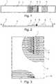
- FIG. 1is an embodiment of a test strip 1 with respect to its front and in FIG. 2 shown in a longitudinal section. Further embodiments of test strips are in the FIGS. 4 to 8 shown.
- the test strip 1consists of a strip-shaped carrier material 2, for example plastic film, and carries on its front side at least one, preferably exactly one, test field 4 for examining a body fluid sample.
- the test strip 1can additionally carry further aids for sample collection or sample examination, for example a lancet.
- a desiccant 6may be arranged, for example based on silica gel.
- the desiccant 6can be applied as a molded part, pill, desiccant bag or film on the carrier material 2 of the test strip 1. It is also possible to integrate the desiccant 6 in adhesive 5, with which the test field 4 is glued to the substrate 2 of the strip.
- test fields 4 of the individual test strips 1are arranged in chambers which are formed by the gluing of the test strips 1.
- adjacent strips 1form the floor and ceiling of a chamber lying between them.
- Side walls of these chambersare formed by the adhesive 7, which connects adjacent test strip 1.
- the lateral chamber wallsmeasured in the stacking direction, have a greater height than the height of the test fields 4 measured in the stacking direction.
- the test fields 4are packed moisture-proof until they are used and protected against harmful environmental influences.
- the test strip stack 10may be surrounded on its side walls by a protective layer 8, which may for example be a film. Particularly suitable are films made of plastic and / or metal, in particular aluminum.
- the film 8is preferably adhered to the stack 10, for example, by the adhesive 7, with the also the individual test strips 1 are glued together.
- the adhesive 7 connecting the test strips 1may cover the side walls of the test strip stack 10 and in this way also form a protective layer.
- the adhesivealso covers the side surfaces of the individual strips 1.
- a protective layer formed of adhesivemay be used alternatively or in addition to a film 8 covering the side walls of the stack 10.
- a film 8are used, which has a low tensile strength and therefore the removal of a test strip 1 from the stack 10 at most insignificantly difficult.
- Metal foils, in particular aluminum foils,can advantageously be made very thin and have a tear propagation resistance that is less than their breaking strength. In this way it can be achieved that the film 8 tears when removing a test strip 1 from the stack 10 along the test strip 1 to be separated from each other.
- test strips 1are adhesively bonded together by the adhesive 7, so that the test strips 1 can be removed individually from the stack 10. Suitable bonds are common, for example, between adhesive labels and their carrier films or carrier papers, from which the adhesive labels can be removed for use.
- an adhesive 7for example, a hot melt adhesive can be used.
- test strips 1may be staggered on top of each other.
- the mechanical connection between the test strip 1 to be separated and the remaining stackcan be weakened, for example by scoring, before the introduction of force.
- the adhesive 7preferably adheres differently to the front side and the back side of the test strips 1, so that it always comes off the same strip side when removing a strip 1 from the stack 10.
- a different adhesion of the adhesive 7can be achieved for example by roughening a strip side or by the front and back of the strips 1 made of different material. It is particularly advantageous if the adhesive 1 always comes off the back of the test strip 1.
- By an increased adhesion of the adhesive 7 on the front side of the test stripcan also be advantageous to facilitate the sticking of the test fields 7, for example by the front of the strip 1 has a greater roughness than the back.
- the back side of the test strips 1may be described with visual or machine readable indicia, for example text, for example with information for removing a test strip 1 from the stack 10, instructions for its use and / or product information. Such information may be printed in particular.
- the front of the last strip of test strip stack 10is not covered by another strip.
- the last strip 9 of the stack 10preferably does not carry a test field 4.
- This last strip 9can advantageously serve as a carrier for product information, for example product name, lot number, code number, shelf life and / or date of manufacture.
- the product informationmay be printed on the strip. It is also possible, for example, to provide the product information on a separate information carrier, for example a label or an RFID transponder, which is glued onto the strip.
- a plastic filmcan be used as the carrier material 2 of a test strip 1.
- plastic filmswith a thickness of 200 to 400 micrometers, for example 300 micrometers.
- thicker or thinner plastic filmscan be readily used.
- the film usedis preferably rough on one side. Suitable films can, for example, by the company OfoTec Folien GmbH, Nehren, Germany under designation "OFOPROP 10775" or from DuPont Teijin Films Luxembourg SA, Luxembourg, under the name "Melinex".
- a strip of hydrophilized tissueOn the film can be fixed by means of an adhesive layer, a strip of hydrophilized tissue. Suitable tissue is sold, for example, by the company Sefar Holding AG, Thal, Switzerland under the name "SEFAR PETEX 07-285 / 44".
- a film strip with a detection layercan be glued to the fabric strip to form a test field, so that part of the fabric is uncovered.
- the foil stripconsists for example of polycarbonate or another plastic.
- the foil stripmay have a thickness of 140 microns, although larger or smaller thicknesses may be used.
- Suitable film stripscan be obtained, for example, from LOFO High Tech GmbH, Weil am Rhein, Germany under the name "Pokalon N 40 GL”.
- the detection layer carried by the film stripcontains detection reagents which discolor under the action of glucose. The detection layer contacts the hydrophilized tissue.
- the test stripscan additionally carry a desiccant, for example a film with a bonded desiccant, as sold by GRACE GmbH & Co. KG, Worms, Germany under the name "SP566-10414".
- a lancetmay be glued to the individual test strips, for example a lancing element made of flat steel.
- the front of the test stripmay be provided with an incision which divides the front into two areas. In one of these areas is the test field, in the other is the desiccant or lancet glued.
- a strip 9 of the above-described carrier material of the test stripscan be used.
- This cover strip 9, which preferably carries no test field,can be marked by a black line as a cover.
- test strips and the one cover stripcan be sorted into a slotted receptacle of a holder.
- the number of test strips for a test strip stackcan be chosen freely. For example, 10 to 100, typically 50 test strips can be connected to a stack.
- the strips 1are pressed with a side surface, preferably the longitudinal side, into an adhesive layer.
- adhesivepenetrates into the spaces between the individual strips 1.
- the adhesive layer into which the stack is pressedcan advantageously be applied to a film, which later forms the protective layer 8.
- an aluminum foilthat is, for example, less than 30 microns, especially less than 20 microns, thick can be used.
- Particularly suitableis a 16 micrometer thick aluminum foil, which is coated with hot melt adhesive, for example, with a sold by Wacker AG, Kunststoff, Germany under the name "Vinnapas B500 / VL20" hot melt adhesive.
- the hot melt adhesiveis applied to the film at a thickness of, for example, 100 to 400 microns. At the in FIG. 3 illustrated embodiment, a 200 micron thick layer was used.
- the holdercan be removed, so that the aluminum foil can also be adhered to the remaining side surfaces of the stack.
- the filmis preferably dimensioned so that there is an overlap and the side surfaces of the stack are thus completely covered.
- a self-adhesive labelcan then be glued with product information.
- test strips 1 of the test strip stack 10Possible embodiments of the test strips 1 of the test strip stack 10 are exemplified in FIGS Figures 1 and 2 and FIGS. 4 to 8 are explained below.
- the test field 4can, as in the in the Figures 1 and 2 illustrated embodiment, be arranged on an absorbent layer 3, for example on hydrophilic fabric or non-woven.
- a body fluid samplecan be rapidly taken up by the absorbent layer and in contact with detection reagents of the test field 4 are brought, especially if the absorbent layer protrudes under the test field 4 and thus allows a particularly simple sample application.
- the test field 4can be provided, for example, for a photometric or an electrochemical concentration determination.
- the test field 4comprises detection reagents which upon contact with a sample of body fluid cause a detection reaction that results in a change in a physically measurable quantity, such as color or color intensity for photometric detection or conductivity or other electrical quantity for electrochemical detection ,
- the test field 4may comprise a transparent film which carries the detection chemicals.
- a measurementis made as in the illustrated embodiment on the front of the test strip.
- a transparent filmas the carrier material for the test strip and, accordingly, to carry out the photometric measurement on the backside of the test strip 1.
- test field 4is open on the substrate 2.
- the test field 4forms in this way a survey on the front of the test strip 1.
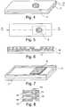
- FIGS. 4 to 6an embodiment of a test strip 1 is shown, in which such a survey can be avoided.
- the in the FIGS. 4 to 6 shown test strip 1has a sandwich-like structure.
- the substrate 2forms a bottom sheet, which carries the test field 4 and a spacer 11.
- a spacer 11for example, double-sided adhesive tape can be used.
- the spacer 11carries a cover sheet 12, which has an opening, via which the test field 4, a body fluid sample can be supplied.
- the openingis disposed above the test field 4. But it is also possible to arrange the opening laterally offset from the test field 4 and the test field 4 is a body fluid sample of the opening by a running between the cover sheet 12 and the bottom sheet 2 Kapillarkanal or the like.
- the test field 4can at the in the FIGS. 4 to 6 illustrated test strips 1 may be formed for an electrochemical detection, for example by 12 electrodes are mounted on the bottom sheet 2 or the cover sheet.
- electrodesmay be printed or formed by laser patterning.
- the in the FIGS. 4 to 6 illustrated test strip 1may also be designed for photometric detection.
- the bottom foil 2can be made in the area of the test field 4 or even completely transparent.
- a photometric measurementcan also be carried out from the other side of the test strip 1, for example through the opening in the cover film 12 or, in the case of an opening arranged laterally offset from the test field 4, by an at least in the region of the test field 4 or even completely transparent Cover film 12 are made.
- test strip 1has a through the bottom sheet 2, the spacer 11 and the cover sheet 12 formed chamber. In a carrier stack 10 of such test strips 1, this chamber is closed by a glued test strip 1. The test strips 1 thus each form a closure of the chamber of an adjacent test strip 1.
- FIGS. 7another embodiment of a test strip 1 is shown.
- the test field 4is surrounded by a circumferential bead 13, which is part of a lateral chamber wall, which encloses the test field 4.
- the bead 13can be formed for example by a glued frame.
- FIG. 8schematically shows another way to form a bead, namely by a circumferential bead.
Landscapes
- Health & Medical Sciences (AREA)
- Engineering & Computer Science (AREA)
- Life Sciences & Earth Sciences (AREA)
- Biomedical Technology (AREA)
- Physics & Mathematics (AREA)
- Chemical & Material Sciences (AREA)
- Analytical Chemistry (AREA)
- Pathology (AREA)
- Immunology (AREA)
- General Physics & Mathematics (AREA)
- General Health & Medical Sciences (AREA)
- Biochemistry (AREA)
- Urology & Nephrology (AREA)
- Medicinal Chemistry (AREA)
- Food Science & Technology (AREA)
- Optics & Photonics (AREA)
- Biophysics (AREA)
- Molecular Biology (AREA)
- Hematology (AREA)
- Investigating Or Analysing Biological Materials (AREA)
- Investigating Or Analyzing Non-Biological Materials By The Use Of Chemical Means (AREA)
Description
Translated fromGermanDie Erfindung betrifft einen Teststreifenstapel mit einzelnen Teststreifen, die übereinander gestapelt sind und ein Testfeld zum Untersuchen einer Körperflüssigkeitsprobe tragen. Ein derartiger Teststreifenstapel ist aus der
Teststreifen ermöglichen zusammen mit entsprechenden Messgeräten eine einfache und schnelle Bestimmung einer Analytkonzentration einer Körperflüssigkeitsprobe, die auch von medizinischen Laien durchgeführt werden kann, beispielsweise zur Messung der Lacatat- oder Cholesterinkonzentration. Teststreifen werden insbesondere auch von Diabetikern verwendet, die mehrmals täglich durch eine Messung der Glucosekonzentration einer Körperflüssigkeitsprobe, in der Regel Blut oder interstitielle Flüssigkeit, ihren Blutzuckerspiegel überprüfen müssen.Test strips together with corresponding measuring devices enable a simple and rapid determination of an analyte concentration of a body fluid sample, which can also be carried out by medical laypersons, for example for measuring the lactate or cholesterol concentration. In particular, test strips are also used by diabetics who have to check their blood sugar levels several times a day by measuring the glucose concentration of a body fluid sample, usually blood or interstitial fluid.
Die Testfelder von Teststreifen sind in der Regel empfindlich und müssen deshalb bis zum Gebrauch vor schädlichen Umwelteinflüssen geschützt werden. Aufgabe der vorliegenden Erfindung ist es, hierfür einen kostengünstigen Weg aufzuzeigen.The test fields of test strips are usually sensitive and must therefore be protected from harmful environmental influences until they are used. Object of the present invention is to show this a cost effective way.
Diese Aufgabe wird erfindungsgemäß durch einen Teststreifenstapel nach Anspruch 1 gelöst. Die Testfelder der Teststreifen sind in Kammern eingeschlossen, wobei benachbarte Teststreifen Boden und Verschluss einer solchen Kammer bilden. Die Kammern können durch das Verkleben der Streifen gebildet sein, so dass benachbarte Streifen Boden und Decke einer zwischen ihnen liegenden Kammer bilden. Möglich ist es aber auch, dass ein Teststreifen eine Kammer enthält, die eine durch einen benachbarten Streifen verschlossene Öffnung aufweist.This object is achieved by a test strip stack according to
Vorteilhaft ist in einem erfindungsgemäßen Teststreifenstapel jedes einzelne Testfeld bis zu seinem Gebrauch in einer Kammer vor schädlichen Umwelteinflüssen geschützt. Da diese Kammer von den die Testfelder tragenden Streifen gebildet wird, kann mit geringerem Aufwand eine feuchtigkeitsdichte Verpackung erreicht werden.In a test strip stack according to the invention, each individual test field is advantageously protected against harmful environmental influences until it is used in a chamber. Since this chamber is formed by the strips carrying the test fields, a moisture-proof packaging can be achieved with less effort.
Bei einem erfindungsgemäßen Verfahren zum Herstellen eines solchen Teststreifenstapels werden einzelne Teststreifen, die auf ihrer Vorderseite ein Testfeld tragen, miteinander zu einem Stapel verklebt, indem jeweils die Vorderseite eines Teststreifens mit der Rückseite eines anderen Teststreifens verklebt wird. Dabei werden die Testfelder in Kammern eingeschlossen und darin feuchtigkeitsdicht versiegelt. Die Testfelder können durch das Verkleben der Streifen in Kammern geschlossen werden, indem benachbarte Streifen Boden und Verschluss einer Kammer bilden. Der Verschluss kann dabei ein Decke einer Kammer bilden oder lediglich eine Öffnung in einer Kammerdecke abdecken.In a method according to the invention for producing such a test strip stack, individual test strips bearing a test field on their front side are glued together to form a stack by bonding the front side of one test strip to the back side of another test strip. The test fields are enclosed in chambers and sealed in moisture-proof. The test panels can be closed by adhering the strips in chambers, with adjacent strips forming the bottom and closure of a chamber. The closure can form a ceiling of a chamber or cover only an opening in a chamber ceiling.
Zum Verkleben der einzelnen Teststreifen kann auf jeden Teststreifen umlaufend ein Klebstoffstrang aufgebracht werden, so dass die Teststreifen beim Aufeinandersetzen miteinander verkleben. Der Aufwand, auf jeden einzelnen Teststreifen einen separaten Klebstoffstrang aufzutragen, lässt sich vermeiden, indem die einzelnen Teststreifen zum Verkleben in eine Halterung eingelegt werden, welche die einzelnen Streifen in einem Abstand voneinander so hält, dass die Vorderseite eines Streifens der Rückseite des mit ihm zu verklebenden Streifens zugewandt ist. Anschließend kann Klebstoff in die Abstände zwischen den Streifen eingefüllt werden. Vorteilhaft kann auf diese Weise zwischen alle Streifen eines Stapels gleichzeitig Klebstoff eingefüllt werden.To glue the individual test strips, an adhesive strand can be applied peripherally to each test strip, so that the test strips stick together when they are put together. The effort to apply a separate adhesive strand on each test strip can be avoided by inserting the individual test strips for gluing into a holder which holds the individual Hold strip at a distance from each other so that the front of a strip faces the back of the strip to be bonded to it. Then glue can be filled in the gaps between the strips. Advantageously can be filled in this way between all strips of a stack simultaneously adhesive.
Beispielsweise kann die mittels der Halterung gebildete Teststreifenanordnung mit ihren Seitenflächen in flüssigen Klebstoff getaucht werden, so dass der Klebstoff in die Zwischenräume zwischen den einzelnen Streifen eindringt. Durch die Tiefe, mit welcher die Teststreifenanordnung dabei in dem flüssigen Klebstoff eintaucht, kann vorgegeben werden, auf welcher Breite die Teststreifen an ihren Rändern mit Klebstoff bedeckt werden. Indem zunächst eine Seitenfläche der Teststreifenanordnung in Klebstoff getaucht wird, kann die Anordnung stabilisiert werden, so dass die Halterung entfernt werden kann. Anschließend können die anderen Seitenflächen der Teststreifenanordnung bzw. des Teststreifenstapels in Klebstoff getaucht werden, so dass die Testfelder umlaufend von Klebstoff umgeben sind.For example, the test strip assembly formed by the holder can be dipped with its side surfaces in liquid adhesive, so that the adhesive penetrates into the spaces between the individual strips. Due to the depth with which the test strip arrangement dips into the liquid adhesive, the width at which the test strips are covered with adhesive at their edges can be specified. By first dipping a side surface of the test strip assembly in adhesive, the assembly can be stabilized so that the support can be removed. Subsequently, the other side surfaces of the test strip arrangement or of the test strip stack can be dipped in adhesive so that the test fields are encircled by adhesive.
Ein Teststreifenstapel enthält notwendigerweise stets einen Streifen, dessen Vorderseite nicht von einem weiteren Streifen bedeckt ist, da dieser Teststreifen eine Stirnseite des Stapels bildet. Dieser unbedeckte Streifen kann ebenso wie die anderen Streifen des Stapels ein Testfeld tragen. Da ein solches Testfeld jedoch nicht vor schädlichen Umwelteinflüssen geschützt wäre, kann es im Regelfall nicht verwendet werden. Bevorzugt wird der Teststreifenstapel deshalb von einem Streifen ohne Testfeld abgeschlossen. Dies bedeutet, dass das letzte Testfeld eines Stapels von einem Streifen ohne Testfeld bedeckt ist.A test strip stack necessarily always contains a strip whose front is not covered by another strip, since this test strip forms an end face of the stack. This uncovered strip may carry a test field as well as the other strips of the stack. However, since such a test field would not be protected against harmful environmental influences, it can not be used as a rule. The test strip stack is therefore preferably terminated by a strip without a test field. This means that the last test field of a stack is covered by a strip without a test field.
Wie erläutert betrifft die vorliegende Erfindung einen Teststreifenstapel aus einzelnen Teststreifen. Das Wort "einzeln" wird im Rahmen der vorliegenden Erfindung gebraucht, um die Teststreifen eines erfindungsgemäßen Teststreifenstapels von einem kontinuierlichen Band zu unterscheiden, das mehrere Testfelder trägt und zu einem Stapel gefaltet ist. Einzelne Teststreifen haben eine Vorderseite, eine Rückseite und - im Gegensatz zu einem endlosen Band - eine umlaufende Seite, welche die Vorderseite mit der Rückseite verbindet. Da Teststreifen in der Regel aus Folie gefertigt sind und deshalb typischerweise recht dünn sind, können die Seitenflächen entsprechend sehr schmal und im Extremfalls nur eine Kante sein. Bei einem einzelnen Teststreifen ist jedoch stets eine umlaufende Seite vorhanden, die in der Regel eine Schnittfläche ist, an welcher der Streifen bei seiner Herstellung aus einer größeren Folie ausgeschnitten wurde.As explained, the present invention relates to a test strip stack of individual test strips. The term "single" is used in the present invention to distinguish the test strips of a test strip stack according to the invention from a continuous strip which carries a plurality of test fields and is folded into a stack. Individual test strips have a front side, a back side and, unlike an endless belt, a circumferential side which connects the front side to the back side. Since test strips are usually made of foil and are therefore typically quite thin, the side surfaces accordingly very narrow and in extreme cases only one edge. However, a single test strip always has a circumferential side, which is usually a cut surface on which the strip was cut out of a larger foil during its manufacture.
Weitere Einzelheiten und Vorteile der Erfindung werden an einem Ausführungsbeispiel unter Bezugnahme auf die beigefügten Zeichnungen erläutert. Es zeigen:
- Figur 1:
- ein Ausführungsbeispiel eines von einem erfindungsgemäßen Teststreifenstapel abgenommenen Teststreifens;
- Figur 2:
- ein Längsschnitt zu
Figur 1 - Figur 3:
- ein Ausführungsbeispiel eines erfindungsgemäßen Teststreifenstapels aus Teststreifen gemäß
Figur 1 Figur 4- eine weiteres Ausführungsbeispiel eines von einem erfindungsgemäßen Teststreifenstapel abgenommenen Teststreifens;
Figur 5- eine weitere Ansicht zu
Figur 4 Figur 6- eine Schnittansicht zu
Figur 5 Figur 7- ein weiteres Ausführungsbeispiel eines von einem erfindungsgemäßen Teststreifenstapel abgenommenen Teststreifens;
Figur 8- eine schematische Darstellung eines Ausschnitts einer Schnittansicht eines Ausführungsbeispiels eines erfindungsgemäßen Teststreifenstapels.
- FIG. 1:
- an embodiment of a removed from a test strip stack test strip according to the invention;
- FIG. 2:
- a longitudinal section too
FIG. 1 ; - FIG. 3:
- an embodiment of a test strip stack according to the invention from test strips according to
FIG. 1 in a schematic representation - FIG. 4
- a further embodiment of a test strip removed from a test strip stack according to the invention;
- FIG. 5
- another view too
FIG. 4 ; - FIG. 6
- a sectional view too
FIG. 5 along the section line AA; - FIG. 7
- a further embodiment of a test strip removed from a test strip stack according to the invention;
- FIG. 8
- a schematic representation of a section of a sectional view of an embodiment of a test strip stack according to the invention.
In
Neben dem Testfeld 4 kann ein Trockenmittel 6 angeordnet sein, beispielsweise auf Basis von Silicagel. Das Trockenmittel 6 kann als Formteil, Pille, Trockenmittelbeutel oder Folie auf dem Trägermaterial 2 des Teststreifens 1 angebracht werden. Möglich ist es auch, das Trockenmittel 6 in Klebstoff 5 zu integrieren, mit dem das Testfeld 4 auf dem Trägermaterial 2 des Streifens festgeklebt ist.In addition to the
Der Teststreifen 1 weist umlaufend einen Klebstoffstrang 7 auf, der ebenfalls Trockenmittel enthalten kann. Mit dem umlaufenden Klebstoffstrang 7 werden mehrere einzelne Teststreifen 1 zu einem Teststreifenstapel 10 zusammengeklebt, der beispielhaft in
In dem Teststreifenstapel 10 sind die Testfelder 4 der einzelnen Teststreifen 1 in Kammern angeordnet, die durch das Verkleben der Teststreifen 1 gebildet sind. Dabei bilden benachbarte Streifen 1 Boden und Decke einer zwischen ihnen liegenden Kammer. Seitenwände dieser Kammern werden dabei von dem Klebstoff 7 gebildet, der benachbarte Teststreifen 1 verbindet. Beim Verkleben der Teststreifen 1 werden die Testfelder also in Kammern eingeschlossen. Ein Teststreifen 1, der dabei eine Decke einer solchen Kammer bildet, bildet zugleich auch einen Verschluss der Kammer.In the
Bevorzugt haben die seitlichen Kammerwände in Stapelrichtung gemessen eine größere Höhe als die in Stapelrichtung gemessene Höhe der Testfelder 4. In diesen Kammern sind die Testfelder 4 bis zum Gebrauch feuchtigkeitsdicht verpackt und vor schädlichen Umwelteinflüssen geschützt.Preferably, the lateral chamber walls, measured in the stacking direction, have a greater height than the height of the
Der Teststreifenstapel 10 kann an seinen Seitenwänden von einer Schutzschicht 8 umgeben sein, die beispielsweise eine Folie sein kann. Besonders geeignet sind Folien aus Kunststoff und/oder Metall, insbesondere Aluminium. Die Folie 8 ist bevorzugt auf den Stapel 10 aufgeklebt, beispielsweise von dem Klebstoff 7, mit dem auch die einzelnen Teststreifen 1 miteinander verklebt sind. Der die Teststreifen 1 verbindende Klebstoff 7 kann die Seitenwände des Teststreifenstapels 10 bedecken und auf diese Weise ebenfalls eine Schutzschicht bilden. Der Klebstoff bedeckt dabei auch die Seitenflächen der einzelnen Streifen 1.The
Eine aus Klebstoff gebildete Schutzschicht kann alternativ oder zusätzlich zu einer die Seitenwände des Stapels 10 bedeckenden Folie 8 verwendet werden. Besonders vorteilhaft kann als Schutzschicht eine Folie 8 verwendet werden, die eine geringe Reißfestigkeit aufweist und deshalb das Abnehmen eines Teststreifens 1 von dem Stapel 10 allenfalls unwesentlich erschwert. Metallfolien, insbesondere Aluminiumfolien, können vorteilhaft sehr dünn ausgebildet sein und eine Weiterreißfestigkeit aufweisen, die geringer als ihre Bruchfestigkeit ist. Auf diese Weise lässt sich erreichen, dass die Folie 8 beim Abnehmen eines Teststreifens 1 von dem Stapel 10 entlang der voneinander zu trennenden Teststreifen 1 reißt.A protective layer formed of adhesive may be used alternatively or in addition to a
Die Teststreifen 1 sind durch den Klebstoff 7 lösbar miteinander verklebt, so dass die Teststreifen 1 einzelnen von dem Stapel 10 abgenommen werden können. Geeignete Verklebungen sind beispielsweise zwischen Klebeetiketten und deren Trägerfolien oder Trägerpapieren üblich, von denen die Klebeetiketten zum Gebrauch abgezogen werden können. Als Klebstoff 7 kann beispielsweise auch ein Schmelzkleber verwendet werden.The
Um einen einzelnen Teststreifen 1 von dem Stapel 10 abzunehmen, kann auf eine Kante des obersten Teststreifens 1 manuell oder mit einem geeigneten Gerät eine Kraft ausgeübt werden, so dass sich der Teststreifen 1 von dem Stapel 10 löst und abziehen lässt. Um das Abziehen eines Teststreifens 1 zu erleichtern, können die Teststreifen 1 versetzt aufeinander gestapelt sein. Indem ein Teststreifen 1 seitlich oder an einem seiner Enden über den mit ihm verklebten Teststreifen 1 übersteht, lässt sich der abzunehmende Teststreifen leichter fassen und ablösen.In order to remove a
Um zu verhindern, dass versehentlich ein Teilstapel mit zwei oder mehr Teststreifen 1 vom Stapel 10 gelöst wird, kann vor der Krafteinleitung die mechanische Verbindung zwischen dem abzutrennenden Teststreifen 1 und dem restlichen Stapel geschwächt werden, beispielsweise durch Einkerben.To prevent inadvertent release of a partial stack with two or
Bevorzugt haftet der Klebstoff 7 an der Vorderseite und der Rückseite der Teststreifen 1 unterschiedlich, so dass er sich beim Abnehmen eines Streifens 1 von dem Stapel 10 stets von derselben Streifenseite löst. Eine unterschiedliche Haftung des Klebstoffs 7 kann beispielsweise durch Aufrauen einer Streifenseite erreicht werden oder indem Vorder- und Rückseite der Streifen 1 aus unterschiedlichem Material bestehen. Besonders vorteilhaft ist es, wenn sich der Klebstoff 1 stets von der Rückseite des Teststreifens 1 löst. Durch eine erhöhte Haftung des Klebstoffs 7 an der Vorderseite des Teststreifens lässt sich vorteilhaft auch das Aufkleben der Testfelder 7 erleichtern, beispielsweise indem die Vorderseite des Streifens 1 eine größere Rauhigkeit als die Rückseite aufweist.The adhesive 7 preferably adheres differently to the front side and the back side of the
Die Rückseite der Teststreifen 1 kann mit visuell- oder maschinenlesbaren Zeichen, beispielsweise Text, beschrieben sein, beispielsweise mit Informationen zum Abnehmen eines Teststreifens 1 von dem Stapel 10, Hinweisen für deren Verwendung und/oder Produktinformationen. Derartige Informationen können insbesondere aufgedruckt sein.The back side of the
Die Vorderseite des letzten Streifens eines Teststreifenstapels 10 ist nicht von einem weiteren Streifen bedeckt. Wie bereits erwähnt trägt der letzte Streifen 9 des Stapels 10 bevorzugt kein Testfeld 4. Dieser letzte Streifen 9 kann vorteilhaft als Träger für Produktinformationen, beispielsweise Produktbezeichnung, Lotnummer, Codenummer, Haltbarkeits- und/oder Herstellungsdatum, dienen. Die Produktinformation kann auf den Streifen aufgedruckt sein. Möglich ist es beispielsweise auch, die Produktinformation auf einem separaten Informationsträger, beispielsweise einem Etikett oder einem RFID-Transponder vorzusehen, der auf den Streifen aufgeklebt ist.The front of the last strip of
Wie bereits erwähnt, kann als Trägermaterial 2 eines Teststreifens 1 eine Kunststofffolie verwendet werden. Gut geeignet sind insbesondere Kunststofffolien mit einer Dicke von 200 bis 400 Mikrometer, beispielsweise 300 Mikrometer. Es können jedoch ohne weiteres auch dickere oder dünnere Kunststofffolien verwendet werden. Die verwendete Folie ist bevorzugt einseitig rau. Geeignete Folien können beispielsweise von der Firma OfoTec Folien GmbH, Nehren, Deutschland unter Bezeichnung "OFOPROP 10775" oder von der Firma DuPont Teijin Films Luxembourg S.A., Luxemburg, unter der Bezeichnung "Melinex" bezogen werden.As already mentioned, a plastic film can be used as the
Auf die Folie kann mittels einer Klebeschicht ein Streifen eines hydrophilisierten Gewebes fixiert werden. Geeignetes Gewebe wird beispielsweise von der Firma Sefar Holding AG, Thal, Schweiz unter der Bezeichnung "SEFAR PETEX 07-285/44" vertrieben. Auf den Gewebestreifen kann zur Ausbildung eines Testfelds ein Folienstreifen mit einer Nachweisschicht aufgeklebt werden, so dass ein Teil des Gewebes unbedeckt ist. Der Folienstreifen besteht beispielsweise aus Polycarbonat oder einem anderen Kunststoff. Der Folienstreifen kann beispielsweise eine Dicke von 140 Mikrometer haben, wobei auch größere oder kleinere Dicken verwendet werden können. Geeignete Folienstreifen können beispielsweise von der Firma LOFO High Tech GmbH, Weil am Rhein, Deutschland unter der Bezeichnung "Pokalon N 40 GL" bezogen werden. Die von dem Folienstreifen getragene Nachweisschicht enthält Nachweisreagenzien, welche sich unter der Einwirkung von Glukose verfärben. Die Nachweisschicht kontaktiert das hydrophilierte Gewebe.On the film can be fixed by means of an adhesive layer, a strip of hydrophilized tissue. Suitable tissue is sold, for example, by the company Sefar Holding AG, Thal, Switzerland under the name "SEFAR PETEX 07-285 / 44". A film strip with a detection layer can be glued to the fabric strip to form a test field, so that part of the fabric is uncovered. The foil strip consists for example of polycarbonate or another plastic. For example, the foil strip may have a thickness of 140 microns, although larger or smaller thicknesses may be used. Suitable film strips can be obtained, for example, from LOFO High Tech GmbH, Weil am Rhein, Germany under the name "Pokalon N 40 GL". The detection layer carried by the film strip contains detection reagents which discolor under the action of glucose. The detection layer contacts the hydrophilized tissue.
Die Teststreifen können zusätzlich ein Trockenmittel tragen, beispielsweise eine Folie mit gebundenem Trockenmittel, wie sie von der Firma GRACE GmbH & Co. KG, Worms, Deutschland unter der Bezeichnung "SP566-10414" vertrieben wird. Zusätzlich kann auf die einzelnen Teststreifen eine Lanzette aufgeklebt sein, beispielsweise ein Stechelement aus Flachstahl. Die Vorderseite des Teststreifens kann mit einem Einschnitt versehen sein, der die Vorderseite in zwei Bereiche unterteilt. In einem dieser Bereiche ist das Testfeld, in dem anderen ist das Trockenmittel oder die Lanzette aufgeklebt.The test strips can additionally carry a desiccant, for example a film with a bonded desiccant, as sold by GRACE GmbH & Co. KG, Worms, Germany under the name "SP566-10414". In addition, a lancet may be glued to the individual test strips, for example a lancing element made of flat steel. The front of the test strip may be provided with an incision which divides the front into two areas. In one of these areas is the test field, in the other is the desiccant or lancet glued.
Zur Abdeckung des letzten Testfeldes 4 eines Teststreifenstapels 10 kann ein Streifen 9 aus dem vorstehend beschriebenen Trägermaterial der Teststreifen verwendet werden. Dieser Deckstreifen 9, der bevorzugt kein Testfeld trägt, kann durch einen schwarzen Strich als Abdeckung markiert werden.To cover the
Um einen Teststreifenstapel herzustellen, können die einzelnen Teststreifen und der eine Deckstreifen in eine geschlitzte Aufnahme einer Halterung einsortiert werden. Die Anzahl der Teststreifen für einen Teststreifenstapel kann frei gewählt werden. Beispielsweise können 10 bis 100, typischerweise 50 Teststreifen zu einem Stapel verbunden werden.In order to produce a test strip stack, the individual test strips and the one cover strip can be sorted into a slotted receptacle of a holder. The number of test strips for a test strip stack can be chosen freely. For example, 10 to 100, typically 50 test strips can be connected to a stack.
Nach dem Einsortieren in die Aufnahme werden die Streifen 1 mit einer Seitenfläche, bevorzugt der Längsseite, in eine Kleberschicht gedrückt. Dabei dringt Klebstoff in die Abstände zwischen den einzelnen Streifen 1 ein. Die Klebstoffschicht, in welche der Stapel gedrückt wird, kann vorteilhaft auf einer Folie aufgebracht sein, welche später die Schutzschicht 8 ausbildet. Beispielsweise kann eine Aluminiumfolie, die beispielsweise weniger als 30 Mikrometer, insbesondere weniger als 20 Mikrometer, dick ist, verwendet werden. Geeignet ist insbesondere eine 16 Mikrometer dicke Aluminiumfolie, die mit Schmelzkleber beschichtet wird, beispielsweise mit einem von der Wacker AG, München, Deutschland unter der Bezeichnung "Vinnapas B500/VL20" vertriebenen Schmelzkleber. Der Schmelzkleber wird auf der Folie mit einer Dicke von beispielsweise 100 bis 400 Mikrometern aufgetragen. Bei dem in
Nachdem die Aluminiumfolie auf eine oder zwei Seitenflächen des Stapels aufgeklebt wurde, kann die Halterung entfernt werden, so dass die Aluminiumfolie auch auf die verbleibenden Seitenflächen des Stapels aufgeklebt werden kann. Die Folie ist dabei bevorzugt so bemessen, dass sich ein Überlapp ergibt und die Seitenflächen des Stapels somit lückenlos bedeckt sind.After the aluminum foil has been adhered to one or two side surfaces of the stack, the holder can be removed, so that the aluminum foil can also be adhered to the remaining side surfaces of the stack. The film is preferably dimensioned so that there is an overlap and the side surfaces of the stack are thus completely covered.
Auf den Deckstreifen des so gebildeten Stapels kann anschließend ein Selbstklebeetikett mit Produktinformationen aufgeklebt werden.On the cover strip of the stack thus formed, a self-adhesive label can then be glued with product information.
Mögliche Ausgestaltungen der Teststreifen 1 des Teststreifenstapels 10 sind beispielhaft in den
Das Testfeld 4 kann, wie bei dem in den
Das Testfeld 4 kann beispielsweise für eine photometrische oder eine elektrochemische Konzentrationsbestimmung vorgesehen sein. Bevorzugt weist das Testfeld 4 Nachweisreagenzien auf, die bei Kontakt mit einer Körperflüssigkeitsprobe eine Nachweisreaktion bewirken, die zu einer Änderung einer physikalisch messbaren Größe führt, beispielsweise der Farbe oder Farbintensität für einen photometrischen Nachweis bzw. der Leitfähigkeit oder einer anderen elektrischen Größe für einen elektrochemischen Nachweis.The
Für eine photometrische Konzentrationsbestimmung kann das Testfeld 4 eine transparente Folie aufweisen, welche die Nachweischemikalien trägt. Bevorzugt wird eine Messung wie bei dem dargestellten Ausführungsbeispiel an der Vorderseite des Teststreifens vorgenommen. Es ist jedoch auch möglich, als Trägermaterial für den Teststreifen eine transparente Folie zu verwenden und dementsprechend die photometrische Messung an der Rückseite des Teststreifens 1 vorzunehmen.For a photometric concentration determination, the
Bei dem in den
Bei dem in den
Das Testfeld 4 kann bei dem in den
Der in den
In den
- 11
- Teststreifentest strips
- 22
- Trägermaterialsupport material
- 33
- Schichtlayer
- 44
- Testfeldtest field
- 55
- Klebstoffadhesive
- 66
- Trockenmitteldesiccant
- 77
- Klebstoffadhesive
- 88th
- Schutzschichtprotective layer
- 99
- DeckstreifenTape
- 1010
- TeststreifenstapelTest strip stack
- 1111
- Abstandshalterspacer
- 1212
- Deckfoliecover sheet
- 1313
- Wulstbead
Claims (14)
- A stack of test strips, comprising individual test strips (1) which are stacked on top of each other and carry a test field (4) for examining a body fluid sample, wherein test strips (1) lying on top of one another are detachably adhesively bonded to each other so that test strips (1) can be individually removed from the stack (10), wherein the test fields (4) are packed in chambers and adjacent test strips (1) form the bottom and the closure of such a chamber, and the strips (1) are adhesively bonded to each other by means of an adhesive (7) that is arranged between them and surrounds the test field (4) arranged between the strips (1).
- The stack according to claim 1,characterized in that the chambers contain a desiccant (6).
- The stack according to any one of the preceding claims,characterized in the adhesive (7) forms lateral chamber walls.
- The stack according to any one of the preceding claims,characterized in that the adhesive (7) adheres differently on the front side than on the back side of the strip (1) so that when removing a strip (1) from the stack (10), the adhesive disengages always from the same strip side.
- The stack according to any one of the preceding claims,characterized in that the stack (10) is surrounded at its lateral sides by a protective layer (8).
- The stack according to any one of the preceding claims,characterized in that the individual strips (1) are stacked offset on top of each other.
- The stack according to any one of the preceding claims,characterized in that the stack (10) is covered on its lateral sides with an adhesive (7).
- The stack according to any one of the preceding claims,characterized in that the stack (10) is encased by a film (8).
- The stack according to claim 8,characterized in that the film (8) is a metal film.
- The stack according to any one of the preceding claims,characterized in that the strips' (1) front sides having an access to the test field (4) are roughened or are covered with a material (2) increasing the adhesion of the adhesive (7).
- The stack according to any one of the preceding claims,characterized in that the back sides of the strips (1) are labeled with human- or machine-readable characters.
- The stack according to any one of the preceding claims,characterized in that the last test field (4) of a stack (10) is covered by a strip (9) without test field (4).
- A method for producing a stack (10) of test strips according to any one of the preceding claims, wherein individual test strips (1) which carry a test field (4) on their front side are adhesively bonded to each other to form a stack (10) in that in each case the front side of a test strip (1) is adhesively bonded to the back side of another test strip (1), and in the course of this, the test fields (4) are enclosed in chambers.
- The method according to claim 13,characterized in that for adhesive bonding, the individual test strips (1) are placed into a holder which holds the individual strips (1) spaced apart from each other so that the front side of a strip (1) faces toward the back side of the strip (1) to which it is to be adhesively bonded, and then adhesive (5) is filled into the gaps between the strips (1).
Priority Applications (2)
| Application Number | Priority Date | Filing Date | Title |
|---|---|---|---|
| EP10752532.1AEP2480884B1 (en) | 2009-09-24 | 2010-09-11 | Test strip stack and method for its production |
| PL10752532TPL2480884T3 (en) | 2009-09-24 | 2010-09-11 | Test strip stack and method for its production |
Applications Claiming Priority (3)
| Application Number | Priority Date | Filing Date | Title |
|---|---|---|---|
| EP09012125 | 2009-09-24 | ||
| EP10752532.1AEP2480884B1 (en) | 2009-09-24 | 2010-09-11 | Test strip stack and method for its production |
| PCT/EP2010/005579WO2011035861A1 (en) | 2009-09-24 | 2010-09-11 | Stack of test strips and method for the production thereof |
Publications (2)
| Publication Number | Publication Date |
|---|---|
| EP2480884A1 EP2480884A1 (en) | 2012-08-01 |
| EP2480884B1true EP2480884B1 (en) | 2018-08-08 |
Family
ID=41682758
Family Applications (1)
| Application Number | Title | Priority Date | Filing Date |
|---|---|---|---|
| EP10752532.1AActiveEP2480884B1 (en) | 2009-09-24 | 2010-09-11 | Test strip stack and method for its production |
Country Status (6)
| Country | Link |
|---|---|
| US (1) | US8591827B2 (en) |
| EP (1) | EP2480884B1 (en) |
| CN (1) | CN102511005B (en) |
| ES (1) | ES2686125T3 (en) |
| PL (1) | PL2480884T3 (en) |
| WO (1) | WO2011035861A1 (en) |
Families Citing this family (4)
| Publication number | Priority date | Publication date | Assignee | Title |
|---|---|---|---|---|
| EP2480884B1 (en) | 2009-09-24 | 2018-08-08 | Roche Diabetes Care GmbH | Test strip stack and method for its production |
| CN105683742B (en)* | 2013-06-10 | 2018-12-25 | 豪夫迈·罗氏有限公司 | Method and apparatus for manufacturing test elements |
| CN106461642A (en)* | 2014-03-19 | 2017-02-22 | 警戒生物科学公司 | Device for disease condition detection and application thereof |
| WO2017044111A1 (en) | 2015-09-11 | 2017-03-16 | Vigilant Biosciences, Inc. | Device for early detection of disease states |
Family Cites Families (24)
| Publication number | Priority date | Publication date | Assignee | Title |
|---|---|---|---|---|
| CA1185280A (en)* | 1981-05-13 | 1985-04-09 | Frank Wogoman | Test device handling system |
| US4710351A (en)* | 1984-10-04 | 1987-12-01 | Miles Laboratories, Inc. | Automated handling system |
| US4650706A (en)* | 1986-05-12 | 1987-03-17 | Minnesota Mining And Manufacturing Company | Tabbed tape pad |
| US5329686A (en)* | 1991-12-19 | 1994-07-19 | Eastman Kodak Company | Slide frame and manufacturing process |
| DE4313253A1 (en) | 1993-04-23 | 1994-10-27 | Boehringer Mannheim Gmbh | System for analyzing the contents of liquid samples |
| US6319467B1 (en)* | 1994-04-19 | 2001-11-20 | Mclernon, Iii William J. | Allergy test strip |
| DE9413462U1 (en)* | 1994-08-20 | 1994-11-10 | BASF Magnetics (Holding) GmbH, 67059 Ludwigshafen | Packaging for stacked items |
| US5962333A (en)* | 1996-01-25 | 1999-10-05 | Multisorb Technologies, Inc. | Medical diagnostic test strip with desiccant |
| DE19755529A1 (en)* | 1997-12-13 | 1999-06-17 | Roche Diagnostics Gmbh | Analysis system for sample liquids |
| US6514585B1 (en)* | 1998-11-13 | 2003-02-04 | 3M Innovative Properties Company | Tape strip pads and dispenser and method of dispensing individual tape strips |
| DE19956946B8 (en)* | 1999-11-26 | 2005-01-20 | Tesa Ag | Packaging for adhesive films |
| GB2365123A (en)* | 2000-07-20 | 2002-02-13 | Hypoguard Ltd | Test strip |
| US6378701B1 (en) | 2000-12-05 | 2002-04-30 | Teng-Tang Kuo | Auxiliary handle of L shape spanner |
| US6723500B2 (en)* | 2001-12-05 | 2004-04-20 | Lifescan, Inc. | Test strips having reaction zones and channels defined by a thermally transferred hydrophobic barrier |
| US6872358B2 (en)* | 2002-01-16 | 2005-03-29 | Lifescan, Inc. | Test strip dispenser |
| US6787108B2 (en)* | 2002-04-02 | 2004-09-07 | Cmc Daymark Corporation | Plural intrinsic expiration initiation application indicators |
| US7481777B2 (en) | 2006-01-05 | 2009-01-27 | Roche Diagnostics Operations, Inc. | Lancet integrated test element tape dispenser |
| JP4447009B2 (en) | 2003-06-20 | 2010-04-07 | エフ ホフマン−ラ ロッシュ アクチェン ゲゼルシャフト | Test strip with slot vent opening |
| US7735872B1 (en)* | 2003-10-16 | 2010-06-15 | Arkwright George A | Adhesive fastener assembly and method for removably mounting papers |
| AU2005201576B2 (en) | 2004-05-07 | 2010-06-24 | F. Hoffmann-La Roche Ag | Process and device for producing an analytical tape for liquid samples |
| DE102005022022A1 (en) | 2004-05-07 | 2005-12-01 | Roche Diagnostics Gmbh | Manufacture of test strips for e.g. blood glucose determination, comprises transferring test fields from prepared test strip band comprising detection film and adhesive tape, onto carrier tape |
| US7708702B2 (en) | 2006-01-26 | 2010-05-04 | Roche Diagnostics Operations, Inc. | Stack magazine system |
| EP2030566B1 (en) | 2007-08-31 | 2016-08-24 | Roche Diabetes Care GmbH | Analysis system for determining an analyte in a body fluid, magazine for an analysis system and analyzing element, and method for analyzing a body fluid |
| EP2480884B1 (en) | 2009-09-24 | 2018-08-08 | Roche Diabetes Care GmbH | Test strip stack and method for its production |
- 2010
- 2010-09-11EPEP10752532.1Apatent/EP2480884B1/enactiveActive
- 2010-09-11CNCN201080042636.2Apatent/CN102511005B/enactiveActive
- 2010-09-11ESES10752532.1Tpatent/ES2686125T3/enactiveActive
- 2010-09-11PLPL10752532Tpatent/PL2480884T3/enunknown
- 2010-09-11WOPCT/EP2010/005579patent/WO2011035861A1/enactiveApplication Filing
- 2012
- 2012-03-13USUS13/418,945patent/US8591827B2/enactiveActive
Non-Patent Citations (1)
| Title |
|---|
| None* |
Also Published As
| Publication number | Publication date |
|---|---|
| CN102511005A (en) | 2012-06-20 |
| ES2686125T3 (en) | 2018-10-16 |
| US20120224996A1 (en) | 2012-09-06 |
| PL2480884T3 (en) | 2019-01-31 |
| WO2011035861A1 (en) | 2011-03-31 |
| US8591827B2 (en) | 2013-11-26 |
| EP2480884A1 (en) | 2012-08-01 |
| HK1167894A1 (en) | 2012-12-14 |
| CN102511005B (en) | 2015-02-25 |
Similar Documents
| Publication | Publication Date | Title |
|---|---|---|
| DE10315544B4 (en) | Method for producing a piercing and measuring device and device | |
| DE69101707T2 (en) | ARRANGEMENT FOR COLOR CHANGE PRODUCED BY BENDING. | |
| DE602004002738T2 (en) | Packaged medical article with a deployable penetration element for dermal tissue | |
| DE3873787T2 (en) | ANALYTICAL TEST STRIP. | |
| DE69829707T2 (en) | Electrochemical biosensor with a lid | |
| EP1593434B1 (en) | Method for manufacturing a test strip for fluid samples | |
| DE69506267T2 (en) | BLISTER PACK WITH DRYING AGENT | |
| EP2480884B1 (en) | Test strip stack and method for its production | |
| DE102004033317A1 (en) | Analytical test element | |
| CH642026A5 (en) | EMPTY PACKING FOR INSERTING BLISTER STRIPES AND BLISTER PACK. | |
| EP2453796B1 (en) | Optimised lancet strip | |
| WO1999021156A1 (en) | Label for labelling preferably cylindrical containers and a container with a label of this type | |
| DE102007026720A1 (en) | Self-adhesive antenna for an RFID system, in particular for an RFID tag, and method for its production | |
| DE102006052516A1 (en) | Self-adhesive RFID tag and method for its production | |
| DE69607934T2 (en) | ADHESIVE COVER | |
| EP3701423B1 (en) | Security label for detecting improper manipulation attempts | |
| DE3844201C1 (en) | Closure and identification seal | |
| DE102016110380B4 (en) | Adhesive sticker with a labeling field | |
| DE1598463C3 (en) | Test slides for the detection of contact eczema | |
| DE102004032490B4 (en) | Label and method for its production | |
| DE3342256A1 (en) | Dispatch envelope | |
| DE202010007019U1 (en) | Arrangement of a carrier and adhesive seals provided thereon | |
| EP2378970B1 (en) | Lancet having capillary channel and sterile protection and method for producing such a lancet | |
| EP2858816B1 (en) | Packaging film laminate with integrated adhesive strip | |
| EP1943948A1 (en) | Puncture instrument |
Legal Events
| Date | Code | Title | Description |
|---|---|---|---|
| PUAI | Public reference made under article 153(3) epc to a published international application that has entered the european phase | Free format text:ORIGINAL CODE: 0009012 | |
| 17P | Request for examination filed | Effective date:20120424 | |
| AK | Designated contracting states | Kind code of ref document:A1 Designated state(s):AL AT BE BG CH CY CZ DE DK EE ES FI FR GB GR HR HU IE IS IT LI LT LU LV MC MK MT NL NO PL PT RO SE SI SK SM TR | |
| DAX | Request for extension of the european patent (deleted) | ||
| RAP1 | Party data changed (applicant data changed or rights of an application transferred) | Owner name:F.HOFFMANN-LA ROCHE AG Owner name:ROCHE DIABETES CARE GMBH | |
| GRAP | Despatch of communication of intention to grant a patent | Free format text:ORIGINAL CODE: EPIDOSNIGR1 | |
| STAA | Information on the status of an ep patent application or granted ep patent | Free format text:STATUS: GRANT OF PATENT IS INTENDED | |
| INTG | Intention to grant announced | Effective date:20180322 | |
| GRAS | Grant fee paid | Free format text:ORIGINAL CODE: EPIDOSNIGR3 | |
| GRAA | (expected) grant | Free format text:ORIGINAL CODE: 0009210 | |
| STAA | Information on the status of an ep patent application or granted ep patent | Free format text:STATUS: THE PATENT HAS BEEN GRANTED | |
| AK | Designated contracting states | Kind code of ref document:B1 Designated state(s):AL AT BE BG CH CY CZ DE DK EE ES FI FR GB GR HR HU IE IS IT LI LT LU LV MC MK MT NL NO PL PT RO SE SI SK SM TR | |
| REG | Reference to a national code | Ref country code:GB Ref legal event code:FG4D Free format text:NOT ENGLISH | |
| REG | Reference to a national code | Ref country code:AT Ref legal event code:REF Ref document number:1027600 Country of ref document:AT Kind code of ref document:T Effective date:20180815 Ref country code:CH Ref legal event code:EP | |
| REG | Reference to a national code | Ref country code:FR Ref legal event code:PLFP Year of fee payment:9 | |
| REG | Reference to a national code | Ref country code:IE Ref legal event code:FG4D Free format text:LANGUAGE OF EP DOCUMENT: GERMAN | |
| REG | Reference to a national code | Ref country code:DE Ref legal event code:R096 Ref document number:502010015247 Country of ref document:DE | |
| REG | Reference to a national code | Ref country code:NL Ref legal event code:FP | |
| REG | Reference to a national code | Ref country code:ES Ref legal event code:FG2A Ref document number:2686125 Country of ref document:ES Kind code of ref document:T3 Effective date:20181016 | |
| REG | Reference to a national code | Ref country code:LT Ref legal event code:MG4D | |
| PG25 | Lapsed in a contracting state [announced via postgrant information from national office to epo] | Ref country code:IS Free format text:LAPSE BECAUSE OF FAILURE TO SUBMIT A TRANSLATION OF THE DESCRIPTION OR TO PAY THE FEE WITHIN THE PRESCRIBED TIME-LIMIT Effective date:20181208 Ref country code:GR Free format text:LAPSE BECAUSE OF FAILURE TO SUBMIT A TRANSLATION OF THE DESCRIPTION OR TO PAY THE FEE WITHIN THE PRESCRIBED TIME-LIMIT Effective date:20181109 Ref country code:NO Free format text:LAPSE BECAUSE OF FAILURE TO SUBMIT A TRANSLATION OF THE DESCRIPTION OR TO PAY THE FEE WITHIN THE PRESCRIBED TIME-LIMIT Effective date:20181108 Ref country code:LT Free format text:LAPSE BECAUSE OF FAILURE TO SUBMIT A TRANSLATION OF THE DESCRIPTION OR TO PAY THE FEE WITHIN THE PRESCRIBED TIME-LIMIT Effective date:20180808 Ref country code:FI Free format text:LAPSE BECAUSE OF FAILURE TO SUBMIT A TRANSLATION OF THE DESCRIPTION OR TO PAY THE FEE WITHIN THE PRESCRIBED TIME-LIMIT Effective date:20180808 Ref country code:SE Free format text:LAPSE BECAUSE OF FAILURE TO SUBMIT A TRANSLATION OF THE DESCRIPTION OR TO PAY THE FEE WITHIN THE PRESCRIBED TIME-LIMIT Effective date:20180808 Ref country code:BG Free format text:LAPSE BECAUSE OF FAILURE TO SUBMIT A TRANSLATION OF THE DESCRIPTION OR TO PAY THE FEE WITHIN THE PRESCRIBED TIME-LIMIT Effective date:20181108 | |
| PG25 | Lapsed in a contracting state [announced via postgrant information from national office to epo] | Ref country code:LV Free format text:LAPSE BECAUSE OF FAILURE TO SUBMIT A TRANSLATION OF THE DESCRIPTION OR TO PAY THE FEE WITHIN THE PRESCRIBED TIME-LIMIT Effective date:20180808 Ref country code:HR Free format text:LAPSE BECAUSE OF FAILURE TO SUBMIT A TRANSLATION OF THE DESCRIPTION OR TO PAY THE FEE WITHIN THE PRESCRIBED TIME-LIMIT Effective date:20180808 Ref country code:AL Free format text:LAPSE BECAUSE OF FAILURE TO SUBMIT A TRANSLATION OF THE DESCRIPTION OR TO PAY THE FEE WITHIN THE PRESCRIBED TIME-LIMIT Effective date:20180808 | |
| PG25 | Lapsed in a contracting state [announced via postgrant information from national office to epo] | Ref country code:CZ Free format text:LAPSE BECAUSE OF FAILURE TO SUBMIT A TRANSLATION OF THE DESCRIPTION OR TO PAY THE FEE WITHIN THE PRESCRIBED TIME-LIMIT Effective date:20180808 Ref country code:RO Free format text:LAPSE BECAUSE OF FAILURE TO SUBMIT A TRANSLATION OF THE DESCRIPTION OR TO PAY THE FEE WITHIN THE PRESCRIBED TIME-LIMIT Effective date:20180808 Ref country code:EE Free format text:LAPSE BECAUSE OF FAILURE TO SUBMIT A TRANSLATION OF THE DESCRIPTION OR TO PAY THE FEE WITHIN THE PRESCRIBED TIME-LIMIT Effective date:20180808 | |
| REG | Reference to a national code | Ref country code:CH Ref legal event code:PL | |
| REG | Reference to a national code | Ref country code:DE Ref legal event code:R097 Ref document number:502010015247 Country of ref document:DE | |
| PG25 | Lapsed in a contracting state [announced via postgrant information from national office to epo] | Ref country code:SM Free format text:LAPSE BECAUSE OF FAILURE TO SUBMIT A TRANSLATION OF THE DESCRIPTION OR TO PAY THE FEE WITHIN THE PRESCRIBED TIME-LIMIT Effective date:20180808 Ref country code:DK Free format text:LAPSE BECAUSE OF FAILURE TO SUBMIT A TRANSLATION OF THE DESCRIPTION OR TO PAY THE FEE WITHIN THE PRESCRIBED TIME-LIMIT Effective date:20180808 Ref country code:SK Free format text:LAPSE BECAUSE OF FAILURE TO SUBMIT A TRANSLATION OF THE DESCRIPTION OR TO PAY THE FEE WITHIN THE PRESCRIBED TIME-LIMIT Effective date:20180808 | |
| REG | Reference to a national code | Ref country code:BE Ref legal event code:MM Effective date:20180930 | |
| PLBE | No opposition filed within time limit | Free format text:ORIGINAL CODE: 0009261 | |
| STAA | Information on the status of an ep patent application or granted ep patent | Free format text:STATUS: NO OPPOSITION FILED WITHIN TIME LIMIT | |
| REG | Reference to a national code | Ref country code:IE Ref legal event code:MM4A | |
| PG25 | Lapsed in a contracting state [announced via postgrant information from national office to epo] | Ref country code:LU Free format text:LAPSE BECAUSE OF NON-PAYMENT OF DUE FEES Effective date:20180911 Ref country code:MC Free format text:LAPSE BECAUSE OF FAILURE TO SUBMIT A TRANSLATION OF THE DESCRIPTION OR TO PAY THE FEE WITHIN THE PRESCRIBED TIME-LIMIT Effective date:20180808 | |
| 26N | No opposition filed | Effective date:20190509 | |
| PG25 | Lapsed in a contracting state [announced via postgrant information from national office to epo] | Ref country code:IE Free format text:LAPSE BECAUSE OF NON-PAYMENT OF DUE FEES Effective date:20180911 | |
| PG25 | Lapsed in a contracting state [announced via postgrant information from national office to epo] | Ref country code:BE Free format text:LAPSE BECAUSE OF NON-PAYMENT OF DUE FEES Effective date:20180930 Ref country code:CH Free format text:LAPSE BECAUSE OF NON-PAYMENT OF DUE FEES Effective date:20180930 Ref country code:SI Free format text:LAPSE BECAUSE OF FAILURE TO SUBMIT A TRANSLATION OF THE DESCRIPTION OR TO PAY THE FEE WITHIN THE PRESCRIBED TIME-LIMIT Effective date:20180808 Ref country code:LI Free format text:LAPSE BECAUSE OF NON-PAYMENT OF DUE FEES Effective date:20180930 | |
| REG | Reference to a national code | Ref country code:AT Ref legal event code:MM01 Ref document number:1027600 Country of ref document:AT Kind code of ref document:T Effective date:20180911 | |
| PG25 | Lapsed in a contracting state [announced via postgrant information from national office to epo] | Ref country code:MT Free format text:LAPSE BECAUSE OF FAILURE TO SUBMIT A TRANSLATION OF THE DESCRIPTION OR TO PAY THE FEE WITHIN THE PRESCRIBED TIME-LIMIT Effective date:20180808 Ref country code:AT Free format text:LAPSE BECAUSE OF NON-PAYMENT OF DUE FEES Effective date:20180911 | |
| PG25 | Lapsed in a contracting state [announced via postgrant information from national office to epo] | Ref country code:TR Free format text:LAPSE BECAUSE OF FAILURE TO SUBMIT A TRANSLATION OF THE DESCRIPTION OR TO PAY THE FEE WITHIN THE PRESCRIBED TIME-LIMIT Effective date:20180808 | |
| PG25 | Lapsed in a contracting state [announced via postgrant information from national office to epo] | Ref country code:PT Free format text:LAPSE BECAUSE OF FAILURE TO SUBMIT A TRANSLATION OF THE DESCRIPTION OR TO PAY THE FEE WITHIN THE PRESCRIBED TIME-LIMIT Effective date:20180808 Ref country code:HU Free format text:LAPSE BECAUSE OF FAILURE TO SUBMIT A TRANSLATION OF THE DESCRIPTION OR TO PAY THE FEE WITHIN THE PRESCRIBED TIME-LIMIT; INVALID AB INITIO Effective date:20100911 | |
| PG25 | Lapsed in a contracting state [announced via postgrant information from national office to epo] | Ref country code:CY Free format text:LAPSE BECAUSE OF FAILURE TO SUBMIT A TRANSLATION OF THE DESCRIPTION OR TO PAY THE FEE WITHIN THE PRESCRIBED TIME-LIMIT Effective date:20180808 Ref country code:MK Free format text:LAPSE BECAUSE OF NON-PAYMENT OF DUE FEES Effective date:20180808 | |
| PGFP | Annual fee paid to national office [announced via postgrant information from national office to epo] | Ref country code:NL Payment date:20240820 Year of fee payment:15 | |
| PGFP | Annual fee paid to national office [announced via postgrant information from national office to epo] | Ref country code:DE Payment date:20240820 Year of fee payment:15 | |
| PGFP | Annual fee paid to national office [announced via postgrant information from national office to epo] | Ref country code:GB Payment date:20240820 Year of fee payment:15 | |
| PGFP | Annual fee paid to national office [announced via postgrant information from national office to epo] | Ref country code:FR Payment date:20240820 Year of fee payment:15 | |
| PGFP | Annual fee paid to national office [announced via postgrant information from national office to epo] | Ref country code:PL Payment date:20240820 Year of fee payment:15 | |
| PGFP | Annual fee paid to national office [announced via postgrant information from national office to epo] | Ref country code:IT Payment date:20240820 Year of fee payment:15 | |
| PGFP | Annual fee paid to national office [announced via postgrant information from national office to epo] | Ref country code:ES Payment date:20241001 Year of fee payment:15 |