EP2480824B1 - Light engines for lighting devices - Google Patents
Light engines for lighting devicesDownload PDFInfo
- Publication number
- EP2480824B1 EP2480824B1EP10766392.4AEP10766392AEP2480824B1EP 2480824 B1EP2480824 B1EP 2480824B1EP 10766392 AEP10766392 AEP 10766392AEP 2480824 B1EP2480824 B1EP 2480824B1
- Authority
- EP
- European Patent Office
- Prior art keywords
- light
- light engine
- subject matter
- solid state
- mixing chamber
- Prior art date
- Legal status (The legal status is an assumption and is not a legal conclusion. Google has not performed a legal analysis and makes no representation as to the accuracy of the status listed.)
- Active
Links
- 238000002156mixingMethods0.000claimsdescription98
- 239000007787solidSubstances0.000description97
- 239000000463materialSubstances0.000description75
- 230000014509gene expressionEffects0.000description28
- 239000003086colorantSubstances0.000description15
- 229910052751metalInorganic materials0.000description15
- 239000002184metalSubstances0.000description15
- 229910052782aluminiumInorganic materials0.000description11
- XAGFODPZIPBFFR-UHFFFAOYSA-NaluminiumChemical compound[Al]XAGFODPZIPBFFR-UHFFFAOYSA-N0.000description11
- 230000006870functionEffects0.000description9
- 238000002347injectionMethods0.000description8
- 239000007924injectionSubstances0.000description8
- 230000008859changeEffects0.000description7
- 230000005670electromagnetic radiationEffects0.000description6
- 238000005286illuminationMethods0.000description6
- 238000002955isolationMethods0.000description6
- 239000000919ceramicSubstances0.000description5
- 239000011521glassSubstances0.000description5
- 230000005855radiationEffects0.000description5
- 239000004065semiconductorSubstances0.000description5
- 239000004734Polyphenylene sulfideSubstances0.000description4
- NIXOWILDQLNWCW-UHFFFAOYSA-Nacrylic acid groupChemical groupC(C=C)(=O)ONIXOWILDQLNWCW-UHFFFAOYSA-N0.000description4
- 230000008878couplingEffects0.000description4
- 238000010168coupling processMethods0.000description4
- 238000005859coupling reactionMethods0.000description4
- 230000017525heat dissipationEffects0.000description4
- 150000002739metalsChemical class0.000description4
- 239000000203mixtureSubstances0.000description4
- 229920000069polyphenylene sulfidePolymers0.000description4
- 229920001187thermosetting polymerPolymers0.000description4
- 230000000875corresponding effectEffects0.000description3
- 230000005611electricityEffects0.000description3
- 230000020169heat generationEffects0.000description3
- 229920000642polymerPolymers0.000description3
- XEEYBQQBJWHFJM-UHFFFAOYSA-NIronChemical compound[Fe]XEEYBQQBJWHFJM-UHFFFAOYSA-N0.000description2
- 229920000106Liquid crystal polymerPolymers0.000description2
- 239000004977Liquid-crystal polymers (LCPs)Substances0.000description2
- 229910000831SteelInorganic materials0.000description2
- 239000000853adhesiveSubstances0.000description2
- 230000001070adhesive effectEffects0.000description2
- 239000002131composite materialSubstances0.000description2
- 150000001875compoundsChemical class0.000description2
- 230000006835compressionEffects0.000description2
- 238000007906compressionMethods0.000description2
- 238000010276constructionMethods0.000description2
- 230000007423decreaseEffects0.000description2
- 229910003460diamondInorganic materials0.000description2
- 239000010432diamondSubstances0.000description2
- 230000000694effectsEffects0.000description2
- 239000012777electrically insulating materialSubstances0.000description2
- 238000000295emission spectrumMethods0.000description2
- -1lumiphorsSubstances0.000description2
- 238000004519manufacturing processMethods0.000description2
- 229910001092metal group alloyInorganic materials0.000description2
- 229910052752metalloidInorganic materials0.000description2
- 150000002738metalloidsChemical class0.000description2
- 238000000034methodMethods0.000description2
- 230000003287optical effectEffects0.000description2
- 239000002245particleSubstances0.000description2
- 239000004033plasticSubstances0.000description2
- 229920003023plasticPolymers0.000description2
- 229920003229poly(methyl methacrylate)Polymers0.000description2
- 239000004926polymethyl methacrylateSubstances0.000description2
- 230000001105regulatory effectEffects0.000description2
- 239000011347resinSubstances0.000description2
- 229920005989resinPolymers0.000description2
- 230000004044responseEffects0.000description2
- 239000010959steelSubstances0.000description2
- 230000009182swimmingEffects0.000description2
- 229920001169thermoplasticPolymers0.000description2
- 239000004416thermosoftening plasticSubstances0.000description2
- OKTJSMMVPCPJKN-UHFFFAOYSA-NCarbonChemical compound[C]OKTJSMMVPCPJKN-UHFFFAOYSA-N0.000description1
- 239000004593EpoxySubstances0.000description1
- 241000110634Sarcocornia perennisSpecies0.000description1
- 230000032683agingEffects0.000description1
- 230000004075alterationEffects0.000description1
- 230000008901benefitEffects0.000description1
- 229910019990cerium-doped yttrium aluminum garnetInorganic materials0.000description1
- 230000002596correlated effectEffects0.000description1
- 239000008393encapsulating agentSubstances0.000description1
- 238000001125extrusionMethods0.000description1
- 230000002349favourable effectEffects0.000description1
- 239000002657fibrous materialSubstances0.000description1
- 230000004313glareEffects0.000description1
- 229910002804graphiteInorganic materials0.000description1
- 239000010439graphiteSubstances0.000description1
- 239000004519greaseSubstances0.000description1
- 238000010438heat treatmentMethods0.000description1
- 239000000976inkSubstances0.000description1
- 238000009434installationMethods0.000description1
- 238000009413insulationMethods0.000description1
- 239000012212insulatorSubstances0.000description1
- 229910052742ironInorganic materials0.000description1
- 235000020130lebenNutrition0.000description1
- 239000007788liquidSubstances0.000description1
- 239000011159matrix materialSubstances0.000description1
- 229910044991metal oxideInorganic materials0.000description1
- 150000004706metal oxidesChemical class0.000description1
- 230000004048modificationEffects0.000description1
- 238000012986modificationMethods0.000description1
- 230000037361pathwayEffects0.000description1
- 230000008447perceptionEffects0.000description1
- 230000000737periodic effectEffects0.000description1
- 235000020030perryNutrition0.000description1
- 229920001296polysiloxanePolymers0.000description1
- 238000009420retrofittingMethods0.000description1
- 229920006395saturated elastomerPolymers0.000description1
- 238000009987spinningMethods0.000description1
- 239000000126substanceSubstances0.000description1
- 239000000758substrateSubstances0.000description1
- 230000007704transitionEffects0.000description1
- 238000001429visible spectrumMethods0.000description1
Images


Classifications
- F—MECHANICAL ENGINEERING; LIGHTING; HEATING; WEAPONS; BLASTING
- F21—LIGHTING
- F21S—NON-PORTABLE LIGHTING DEVICES; SYSTEMS THEREOF; VEHICLE LIGHTING DEVICES SPECIALLY ADAPTED FOR VEHICLE EXTERIORS
- F21S8/00—Lighting devices intended for fixed installation
- F21S8/02—Lighting devices intended for fixed installation of recess-mounted type, e.g. downlighters
- F21S8/026—Lighting devices intended for fixed installation of recess-mounted type, e.g. downlighters intended to be recessed in a ceiling or like overhead structure, e.g. suspended ceiling
- F—MECHANICAL ENGINEERING; LIGHTING; HEATING; WEAPONS; BLASTING
- F21—LIGHTING
- F21V—FUNCTIONAL FEATURES OR DETAILS OF LIGHTING DEVICES OR SYSTEMS THEREOF; STRUCTURAL COMBINATIONS OF LIGHTING DEVICES WITH OTHER ARTICLES, NOT OTHERWISE PROVIDED FOR
- F21V15/00—Protecting lighting devices from damage
- F21V15/01—Housings, e.g. material or assembling of housing parts
- F—MECHANICAL ENGINEERING; LIGHTING; HEATING; WEAPONS; BLASTING
- F21—LIGHTING
- F21V—FUNCTIONAL FEATURES OR DETAILS OF LIGHTING DEVICES OR SYSTEMS THEREOF; STRUCTURAL COMBINATIONS OF LIGHTING DEVICES WITH OTHER ARTICLES, NOT OTHERWISE PROVIDED FOR
- F21V17/00—Fastening of component parts of lighting devices, e.g. shades, globes, refractors, reflectors, filters, screens, grids or protective cages
- F21V17/002—Fastening of component parts of lighting devices, e.g. shades, globes, refractors, reflectors, filters, screens, grids or protective cages with provision for interchangeability, i.e. component parts being especially adapted to be replaced by another part with the same or a different function
- F—MECHANICAL ENGINEERING; LIGHTING; HEATING; WEAPONS; BLASTING
- F21—LIGHTING
- F21V—FUNCTIONAL FEATURES OR DETAILS OF LIGHTING DEVICES OR SYSTEMS THEREOF; STRUCTURAL COMBINATIONS OF LIGHTING DEVICES WITH OTHER ARTICLES, NOT OTHERWISE PROVIDED FOR
- F21V29/00—Protecting lighting devices from thermal damage; Cooling or heating arrangements specially adapted for lighting devices or systems
- F21V29/50—Cooling arrangements
- F21V29/70—Cooling arrangements characterised by passive heat-dissipating elements, e.g. heat-sinks
- F21V29/74—Cooling arrangements characterised by passive heat-dissipating elements, e.g. heat-sinks with fins or blades
- F21V29/77—Cooling arrangements characterised by passive heat-dissipating elements, e.g. heat-sinks with fins or blades with essentially identical diverging planar fins or blades, e.g. with fan-like or star-like cross-section
- F21V29/773—Cooling arrangements characterised by passive heat-dissipating elements, e.g. heat-sinks with fins or blades with essentially identical diverging planar fins or blades, e.g. with fan-like or star-like cross-section the planes containing the fins or blades having the direction of the light emitting axis
- F—MECHANICAL ENGINEERING; LIGHTING; HEATING; WEAPONS; BLASTING
- F21—LIGHTING
- F21S—NON-PORTABLE LIGHTING DEVICES; SYSTEMS THEREOF; VEHICLE LIGHTING DEVICES SPECIALLY ADAPTED FOR VEHICLE EXTERIORS
- F21S8/00—Lighting devices intended for fixed installation
- F21S8/04—Lighting devices intended for fixed installation intended only for mounting on a ceiling or the like overhead structures
- F21S8/06—Lighting devices intended for fixed installation intended only for mounting on a ceiling or the like overhead structures by suspension
- F21S8/061—Lighting devices intended for fixed installation intended only for mounting on a ceiling or the like overhead structures by suspension with a non-rigid pendant, i.e. a cable, wire or chain
- F—MECHANICAL ENGINEERING; LIGHTING; HEATING; WEAPONS; BLASTING
- F21—LIGHTING
- F21V—FUNCTIONAL FEATURES OR DETAILS OF LIGHTING DEVICES OR SYSTEMS THEREOF; STRUCTURAL COMBINATIONS OF LIGHTING DEVICES WITH OTHER ARTICLES, NOT OTHERWISE PROVIDED FOR
- F21V21/00—Supporting, suspending, or attaching arrangements for lighting devices; Hand grips
- F21V21/14—Adjustable mountings
- F21V21/30—Pivoted housings or frames
- F—MECHANICAL ENGINEERING; LIGHTING; HEATING; WEAPONS; BLASTING
- F21—LIGHTING
- F21V—FUNCTIONAL FEATURES OR DETAILS OF LIGHTING DEVICES OR SYSTEMS THEREOF; STRUCTURAL COMBINATIONS OF LIGHTING DEVICES WITH OTHER ARTICLES, NOT OTHERWISE PROVIDED FOR
- F21V23/00—Arrangement of electric circuit elements in or on lighting devices
- F21V23/02—Arrangement of electric circuit elements in or on lighting devices the elements being transformers, impedances or power supply units, e.g. a transformer with a rectifier
- F—MECHANICAL ENGINEERING; LIGHTING; HEATING; WEAPONS; BLASTING
- F21—LIGHTING
- F21V—FUNCTIONAL FEATURES OR DETAILS OF LIGHTING DEVICES OR SYSTEMS THEREOF; STRUCTURAL COMBINATIONS OF LIGHTING DEVICES WITH OTHER ARTICLES, NOT OTHERWISE PROVIDED FOR
- F21V29/00—Protecting lighting devices from thermal damage; Cooling or heating arrangements specially adapted for lighting devices or systems
- F21V29/50—Cooling arrangements
- F21V29/70—Cooling arrangements characterised by passive heat-dissipating elements, e.g. heat-sinks
- F21V29/74—Cooling arrangements characterised by passive heat-dissipating elements, e.g. heat-sinks with fins or blades
- F—MECHANICAL ENGINEERING; LIGHTING; HEATING; WEAPONS; BLASTING
- F21—LIGHTING
- F21Y—INDEXING SCHEME ASSOCIATED WITH SUBCLASSES F21K, F21L, F21S and F21V, RELATING TO THE FORM OR THE KIND OF THE LIGHT SOURCES OR OF THE COLOUR OF THE LIGHT EMITTED
- F21Y2115/00—Light-generating elements of semiconductor light sources
- F21Y2115/10—Light-emitting diodes [LED]
- Y—GENERAL TAGGING OF NEW TECHNOLOGICAL DEVELOPMENTS; GENERAL TAGGING OF CROSS-SECTIONAL TECHNOLOGIES SPANNING OVER SEVERAL SECTIONS OF THE IPC; TECHNICAL SUBJECTS COVERED BY FORMER USPC CROSS-REFERENCE ART COLLECTIONS [XRACs] AND DIGESTS
- Y10—TECHNICAL SUBJECTS COVERED BY FORMER USPC
- Y10S—TECHNICAL SUBJECTS COVERED BY FORMER USPC CROSS-REFERENCE ART COLLECTIONS [XRACs] AND DIGESTS
- Y10S362/00—Illumination
- Y10S362/80—Light emitting diode
Definitions
- the present inventive subject matteris directed to light engines.
- the present inventive subject matteris directed to light engines that comprise one or more solid state light emitters, e.g., one or more light emitting diodes.
- Solid state light emitterse.g., light emitting diodes
- incandescent light bulbsare very energy-inefficient light sources - about ninety percent of the electricity they consume is released as heat rather than light.
- Fluorescent light bulbsare more efficient than incandescent light bulbs (by a factor of about 10) but are still less efficient than solid state light emitters, such as light emitting diodes.
- incandescent light bulbshave relatively short lifetimes, i.e., typically about 750-1000 hours.
- light emitting diodesfor example, have typical lifetimes between 50,000 and 70,000 hours.
- Fluorescent bulbsgenerally have lifetimes (e.g., 10,000 - 20,000 hours) that are longer than those of incandescent lights, but they typically provide less favorable color reproduction.
- the typical lifetime of conventional fixturesis about 20 years, corresponding to a light-producing device usage of at least about 44,000 hours (based on usage of 6 hours per day for 20 years).
- the need for periodic change-outsis presented.
- the impact of the need to replace light emittersis particularly pronounced where access is difficult (e.g., vaulted ceilings, bridges, high buildings, highway tunnels) and/or where change-out costs are extremely high.
- the ability for the light engine (or lighting device that includes the light engine) to fit in a space that is similar to (or identical to) a space into which conventional devices can fitis important when retro-fitting a lighting device, as well when installing a light engine (or lighting device that includes the light engine) in new construction.
- any particular light emitting diodeis typically concentrated around a single wavelength (as dictated by the light emitting diode's composition and structure), which is desirable for some applications, but not desirable for others, (e.g., for providing general illumination, such an emission spectrum generally does not provide light that appears white, and/or provides a very low CRI).
- light sourcese.g., one or more solid state light emitters and optionally also one or more other types of light sources, e.g., additional light emitting diodes, luminescent materials, incandescent lights, etc.
- additional light emitting diodese.g., additional light emitting diodes, luminescent materials, incandescent lights, etc.
- one or more solid state light emittersmight cease emitting light and/or vary in their intensity of light emission, which can throw off the balance of color output and cause the lighting device to emit light that is perceived as being of a color that differs from the desired color of light output.
- one challenge that necessitates the inclusion of additional componentsis that there may be a desire to provide additional circuitry that can adjust the current supplied to respective solid state light emitters (and/or other light emitters) in order to maintain the balance of color output among the light emitters that emit light of different colors in order to achieve the desired color output.
- Another such challengeis that there may be a desire to mix the light of different colors emitted from the different solid state light emitters by providing additional structure to assist in such mixing.
- one or more solid state light emittersmight vary in their intensity of light emission is temperature change (resulting, e.g., from change in ambient temperature and/or heating up of the solid state light emitters).
- temperature changeresulting, e.g., from change in ambient temperature and/or heating up of the solid state light emitters.
- Some types of solid state light emitterse.g., solid state light emitters that emit light of different colors
- some light emitting diodes that emit red lighthave a very strong temperature dependence in at least some temperature ranges (e.g., AlInGaP light emitting diodes can reduce in optical output by ⁇ 20 % when heated up by ⁇ 40 degrees C, that is, approximately -0.5 % per degree C; some blue light emitting InGaN + YAG:Ce light emitting diodes can reduce in optical output by about - 0.15 % / degree C).
- AlInGaP light emitting diodescan reduce in optical output by ⁇ 20 % when heated up by ⁇ 40 degrees C, that is, approximately -0.5 % per degree C
- some blue light emitting InGaN + YAG:Ce light emitting diodescan reduce in optical output by about - 0.15 % / degree C).
- solid state light emittersAnother example of a reason that one or more solid state light emitters might vary in their intensity of light emission is aging.
- Some solid state light emitterse.g., solid state light emitters that emit light of different colors
- solid state light emittersmight vary in their intensity of light emission is damage to the solid state light emitter(s) and/or damage to circuitry that supplies current to the solid state light emitter(s).
- many light emitting diode light sourceshave average operating lifetimes of decades as opposed to just months or 1-2 years for many incandescent bulbs, but some light emitting diodes' lifetimes can be significantly shortened if they are operated at elevated temperatures.
- a common manufacturer recommendationis that the junction temperature of a light emitting diode should not exceed 85 degrees C if a long lifetime is desired.
- Such a concentration of light outputmay present challenges in providing solid state lighting systems for general illumination in that, in general, a large difference in brightness in a small area may be perceived as glare and may be distracting to occupants.
- a lighting devicein a circuit that has a conventional dimmer.
- Some dimmersoperate based on signals contained in the current supplied to the lighting device (for example, duty cycle of an AC signal, e.g., from a triac), for which additional circuitry is generally needed.
- the present inventive subject matterprovides light engines (and lighting devices that comprise such light engines) that can provide such features.
- light engines for lighting devicesin which the light engines can readily be interchangeably combined with one or more of a wide variety of heat sink modules, one or more of a wide variety of power supply modules, and/or one or more of a wide variety of driver modules that allow for adjustability depending on the desired application for the lighting device.
- light enginesthat each comprise a light engine housing, and a modular mixing chamber element (i.e., a mixing chamber module) and/or a modular driver chamber element (i.e., a driver chamber module), whereby the light engine housing can readily be interchangeably combined with one or more of a wide variety of mixing chamber elements, and/or one or more of a wide variety of driver chamber elements, in order to provide a lighting device or light engine that can accommodate the components needed for the lighting device (or a lighting device that includes the light engine) to satisfy the needs for a particular application (or in order to provide the components needed).
- a modular mixing chamber elementi.e., a mixing chamber module
- a modular driver chamber elementi.e., a driver chamber module
- light enginesthat each comprise a light engine housing, and a mixing chamber element that is removably attached to the light engine housing and/or a driver chamber element that is removably attached to the light engine housing.
- a mixing chamber element that is removable and/or a driver chamber element that is removableone or more of a wide variety of mixing chamber elements, and/or one or more of a wide variety of driver chamber elements can readily be interchanged (i.e., can be selectively combined with the light engine or the lighting device) in order to accommodate the components needed for a particular application (or in order to provide the components needed for such application).
- light engines for lighting devicesin which the light engines can readily be interchangeably combined with one or more trim elements and/or one or more fixture elements (and optionally also one or more heat sink modules, one or more power supply modules, and/or one or more driver modules, as mentioned above).
- a light enginecomprising a light engine housing that comprises at least a first connection element.
- the light engine housingfurther comprises a mixing chamber element and/or a driver chamber element.
- the mixing chamber elementat least in part defining a mixing chamber.
- the connection elementprovides both mechanical connection and thermal coupling between the light engine housing and at least one other component, e.g., a mixing chamber element, a driver chamber element, a fixture housing, a trim element and/or a heat sink module.
- a light enginecomprising a light engine housing to which a variety of mixing chamber elements can be interchangeably connected and/or to which a variety of driver chamber elements can be interchangeably connected (and/or in which a variety of mixing chamber elements can be interchangeably positioned and/or in which a variety of driver chamber elements can be interchangeably positioned).
- a light enginecomprising a light engine housing and at least one light source (e.g., a solid state light emitter), the light engine housing comprising a mixing chamber element, a driver chamber element and at least a first connection element, and the mixing chamber element at least in part defining a mixing chamber in which light from the at least one light source mixes prior to exiting the light engine housing.
- a light engine housingcomprising a mixing chamber element, a driver chamber element and at least a first connection element, and the mixing chamber element at least in part defining a mixing chamber in which light from the at least one light source mixes prior to exiting the light engine housing.
- a lighting devicethat comprises a light engine as described herein, and the lighting device can further comprise at least one fixture element, at least one trim element, and/or at least one heat sink module.
- the fixture element(s), the trim element(s), and/or the heat sink module(s), or any combination thereofis/are attached to a connection element or to respective connection elements.
- the first connection elementhas at least first and second apertures
- the first aperturehas an axis that extends in a first direction
- the second aperturehas an axis that extends in a second direction, the first direction differing from the second direction.
- at least one of the axis of the first aperture and the axis of the second aperturesis substantially parallel to an axis of the light engine housing, and/or at least one of the axis of the first aperture and the axis of the second apertures is substantially perpendicular to an axis of the light engine housing.
- the first connection elementhas at least first and second mounting surfaces, and the first mounting surface and the second mounting surface are not parallel. In some of such embodiments:
- a lighting devicethat comprises a light engine as described herein, and the lighting device can further comprise at least one component selected from among driver components and power supply components.
- the at least one component selected from among driver components and power supply componentsis/are positioned within the driver chamber element.
- a lighting devicethat comprises a light engine as described herein, and the lighting device can further comprise at least one electrical connector.
- in contact withmeans that the first structure that is in contact with a second structure is in direct contact with the second structure or is in indirect contact with the second structure.
- in indirect contact withmeans that the first structure is not in direct contact with the second structure, but that there are a plurality of structures (including the first and second structures), and each of the plurality of structures is in direct contact with at least one other of the plurality of structures (e.g., the first and second structures are in a stack and are separated by one or more intervening layers).
- direct contactas used in the present specification, means that the first structure which is "in direct contact” with a second structure is touching the second structure and there are no intervening structures between the first and second structures at least at some location.
- two components in a deviceare "electrically connected,” means that there are no components electrically between the components that affect the function or functions provided by the device.
- two componentscan be referred to as being electrically connected, even though they may have a small resistor between them which does not materially affect the function or functions provided by the device (indeed, a wire connecting two components can be thought of as a small resistor); likewise, two components can be referred to as being electrically connected, even though they may have an additional electrical component between them which allows the device to perform an additional function, while not materially affecting the function or functions provided by a device which is identical except for not including the additional component; similarly, two components which are directly connected to each other, or which are directly connected to opposite ends of a wire or a trace on a circuit board, are electrically connected.
- a statement herein that two components in a device are "electrically connected”is distinguishable from a statement that the two components are "directly electrically connected", which means that there are no components electrically between the two components.
- firstmay be used herein to describe various elements, components, regions, layers, sections and/or parameters
- these elements, components, regions, layers, sections and/or parametersshould not be limited by these terms. These terms are only used to distinguish one element, component, region, layer or section from another region, layer or section.
- a first element, component, region, layer or section discussed belowcould be termed a second element, component, region, layer or section without departing from the teachings of the present inventive subject matter.
- Relative termssuch as “lower”, “bottom”, “below”, “upper”, “top” or “above,” may be used herein to describe one element's relationship to another elements as illustrated in the Figures. Such relative terms are intended to encompass different orientations of the device in addition to the orientation depicted in the Figures. For example, if the device in the Figures is turned over, elements described as being on the “lower” side of other elements would then be oriented on “upper” sides of the other elements. The exemplary term “lower”, can therefore, encompass both an orientation of “lower” and “upper,” depending on the particular orientation of the figure.
- illuminationmeans that at least some current is being supplied to the solid state light emitter to cause the solid state light emitter to emit at least some electromagnetic radiation (e.g., visible light).
- the expression “illuminated”encompasses situations where the solid state light emitter emits electromagnetic radiation continuously, or intermittently at a rate such that a human eye would perceive it as emitting electromagnetic radiation continuously or intermittently, or where a plurality of solid state light emitters of the same color or different colors are emitting electromagnetic radiation intermittently and/or alternatingly (with or without overlap in "on” times), e.g., in such a way that a human eye would perceive them as emitting light continuously or intermittently (and, in some cases where different colors are emitted, as separate colors or as a mixture of those colors).
- luminescent materialmeans that at least some electromagnetic radiation (e.g., visible light, UV light or infrared light) is contacting the luminescent material, causing the luminescent material to emit at least some light.
- electromagnetic radiatione.g., visible light, UV light or infrared light
- the expression “excited”encompasses situations where the luminescent material emits light continuously, or intermittently at a rate such that a human eye would perceive it as emitting light continuously or intermittently, or where a plurality of luminescent materials that emit light of the same color or different colors are emitting light intermittently and/or alternatingly (with or without overlap in "on” times) in such a way that a human eye would perceive them as emitting light continuously or intermittently (and, in some cases where different colors are emitted, as a mixture of those colors).
- the expression "the first direction differing from the second direction", e.g., as used in the expression "the first aperture having an axis that extends in a first direction, the second aperture having an axis that extends in a second direction, the first direction differing from the second direction"means that an axis of the first aperture and an axis of the second aperture are not identical or parallel.
- axis of the aperturecan refer to a straight line about which the aperture is substantially symmetrical. In instances where the aperture is not substantially symmetrical about any line, the expression “axis of the aperture” can refer to a line about which rotation of a uniform-density object that fills the aperture would be substantially balanced.
- substantially symmetricalwhen referring to a shape, means that the shape is symmetrical or could be made symmetrical by removing a specific region or regions which in total comprise not more than about 10 percent of its volume and/or by adding a specific region or regions which in total comprise not more than about 10 percent of its volume.
- substantially balancedwhen referring to a structure, means that the structure is balanced or could be balanced by adding to a specific location or locations mass that in total comprises not more than about 10 percent of the mass of the structure.
- the expression "the first mounting surface and the second mounting surface not being parallel”, e.g., as used in the expression “the connection element having at least first and second mounting surfaces, the first mounting surface and the second mounting surface not being parallel”means that a first plane defined by the first mounting surface and a second plane defined by the second mounting surface are not parallel or substantially parallel (i.e., that the respective first and second planes do not diverge from each other by more than an angle of 5 degrees.
- first plane defined by the first mounting surfacemeans a plane in which at least 90% of the points in the first mounting surface are located on the plane or between the plane and a second plane that is spaced from the plane by a distance of not more than 5% of the largest dimension of the surface, and likewise for other similar expressions.
- substantially parallelmeans that two lines (or two planes) do not diverge from each other by more than an angle of 5 degrees.
- substantially perpendicularmeans that at least 90% of the points in the structure which is characterized as being substantially perpendicular to a reference plane or line are located on one of or between a pair of planes (1) which are perpendicular to the reference plane, (2) which are parallel to each other and (3) which are spaced from each other by a distance of not more than 5% of the largest dimension of the structure.
- thermal couplingmeans that heat transfer occurs between (or among) the two (or more) items for which there is thermal coupling. Such heat transfer encompasses any and all types of heat transfer, regardless of how the heat is transferred between or among the items. That is, the heat transfer between (or among) items can be by conduction, convection, radiation, or any combinations thereof, and can be directly from one of the items to the other, or indirectly through one or more intervening elements or spaces (which can be solid, liquid and/or gaseous) of any shape, size and composition.
- thermal couplingencompasses structures that are "adjacent" (as defined herein) to one another.
- the majority of the heat transferred from the light sourceis transferred by conduction; in other situations / embodiments, the majority of the heat that is transferred from the light source is transferred by convection; and in some situations / embodiments, the majority of the heat that is transferred from the light source is transferred by a combination of conduction and convection.
- adjacentmeans that the first and second structures are next to each other. That is, where the structures that are described as being “adjacent” to one another are similar, no other similar structure is positioned between the first structure and the second structure (for example, where two dissipation elements are adjacent to each other, no other dissipation element is positioned between them). Where the structures that are described as being “adjacent” to one another are not similar, no other structure is positioned between them.
- a lighting devicecan be a device which illuminates an area or volume, e.g., a structure, a swimming pool or spa, a room, a warehouse, an indicator, a road, a parking lot, a vehicle, signage, e.g., road signs, a billboard, a ship, a toy, a mirror, a vessel, an electronic device, a boat, an aircraft, a stadium, a computer, a remote audio device, a remote video device, a cell phone, a tree, a window, an LCD display, a cave, a tunnel, a yard, a lamppost, or a device or array of devices that illuminate an enclosure, or a device that is used for edge or back-lighting (e.g., back light poster, signage, LCD displays), bulb replacements (e.g., for replacing AC incandescent lights, low voltage lights, fluorescent lights
- the present inventive subject matterfurther relates to an illuminated enclosure (the volume of which can be illuminated uniformly or non-uniformly), comprising an enclosed space and at least one light engine according to the present inventive subject matter, wherein the light engine illuminates at least a portion of the enclosed space (uniformly or non-uniformly).
- Some embodiments of the present inventive subject mattercomprise at least a first power line, and some embodiments of the present inventive subject matter are directed to a structure comprising a surface and at least one light engine corresponding to any embodiment of a light engine according to the present inventive subject matter as described herein, wherein if current is supplied to the first power line, and/or if at least one solid state light emitter in the light engine is illuminated, the light engine would illuminate at least a portion of the surface.
- the present inventive subject matteris further directed to an illuminated area, comprising at least one item, e.g., selected from among the group consisting of a structure, a swimming pool or spa, a room, a warehouse, an indicator, a road, a parking lot, a vehicle, signage, e.g., road signs, a billboard, a ship, a toy, a mirror, a vessel, an electronic device, a boat, an aircraft, a stadium, a computer, a remote audio device, a remote video device, a cell phone, a tree, a window, an LCD display, a cave, a tunnel, a yard, a lamppost, etc., having mounted therein or thereon at least one light engine as described herein.
- at least one iteme.g., selected from among the group consisting of a structure, a swimming pool or spa, a room, a warehouse, an indicator, a road, a parking lot, a vehicle, signage, e.g., road signs,
- the present inventive subject matteris directed to a light engine that comprises a light engine housing and at least one solid state light emitter, in which the light engine housing comprises at least one connection element, and in some embodiments, the light engine housing further comprises a mixing chamber element and/or a driver chamber element.
- Some or all of the one or more solid state light emitterscan be provided in the light engine housing, e.g., in a mixing chamber element and/or in a driver chamber element.
- solid state light emittersany suitable solid state light emitter (or solid state light emitters) can be employed in the light engines according to the present inventive subject matter.
- solid state light emittersare well known, and any of such light emitters can be employed according to the present inventive subject matter.
- Representative examples of solid state light emittersinclude light emitting diodes (inorganic or organic, including polymer light emitting diodes (PLEDs)) with or without luminescent materials.
- Solid state light emittersthat emit light having a desired peak emission wavelength and/or dominant emission wavelength, and any of such solid state light emitters (discussed in more detail below), or any combinations of such solid state light emitters, can be employed in embodiments that comprise a solid state light emitter.
- Light emitting diodesare semiconductor devices that convert electrical current into light.
- a wide variety of light emitting diodesare used in increasingly diverse fields for an ever-expanding range of purposes. More specifically, light emitting diodes are semiconducting devices that emit light (ultraviolet, visible, or infrared) when a potential difference is applied across a p-n junction structure.
- light emitting diodesare semiconducting devices that emit light (ultraviolet, visible, or infrared) when a potential difference is applied across a p-n junction structure.
- a light emitting diodeproduces light by exciting electrons across the band gap between a conduction band and a valence band of a semiconductor active (light-emitting) layer.
- the electron transitiongenerates light at a wavelength that depends on the band gap.
- the color of the light (wavelength)and/or the type of electromagnetic radiation, e.g., infrared light, visible light, ultraviolet light, near ultraviolet light, etc., and any combinations thereof
- a light emitting diodedepends on the semiconductor materials of the active layers of the light emitting diode.
- light emitting diodeis used herein to refer to the basic semiconductor diode structure (i.e., the chip).
- the commonly recognized and commercially available "LED” that is sold (for example) in electronics storestypically represents a “packaged” device made up of a number of parts.
- These packaged devicestypically include a semiconductor based light emitting diode such as (but not limited to) those described in U.S. Pat. Nos. 4,918,487 ; 5,631,190 ; and 5,912,477 ; various wire connections, and a package that encapsulates the light emitting diode.
- Light engines according to the present inventive subject mattercan, if desired, further comprise one or more luminescent materials.
- a luminescent materialis a material that emits a responsive radiation (e.g., visible light) when excited by a source of exciting radiation.
- a responsive radiatione.g., visible light
- the responsive radiationhas a wavelength that is different from the wavelength of the exciting radiation.
- Luminescent materialscan be categorized as being down-converting, i.e., a material that converts photons to a lower energy level (longer wavelength) or up-converting, i.e., a material that converts photons to a higher energy level (shorter wavelength).
- luminescent materialOne type of luminescent material are phosphors, which are readily available and well known to persons of skill in the art. Other examples of luminescent materials include scintillators, day glow tapes and inks that glow in the visible spectrum upon illumination with ultraviolet light.
- luminescent materialsthat emit light having a desired peak emission wavelength and/or dominant emission wavelength, or a desired hue, and any of such luminescent materials, or any combinations of such luminescent materials, can be employed, if desired.
- the one or more luminescent materialscan be provided in any suitable form.
- the luminescent elementcan be embedded in a resin (i.e., a polymeric matrix), such as a silicone material, an epoxy material, a glass material or a metal oxide material, and/or can be applied to one or more surfaces of a resin, to provide a lumiphor.
- a resini.e., a polymeric matrix
- the one or more solid state light emitterscan be arranged in any suitable way.
- suitable solid state light emittersincluding suitable light emitting diodes, luminescent materials, lumiphors, encapsulants, etc. that may be used in practicing the present inventive subject matter, are described in:
- light of any number of colorscan be mixed by the light engines according to the present inventive subject matter.
- Representative examples of blending of light colorsare described in:
- a mixing chamber elementcan be of any suitable shape and size, and can be made of any suitable material or materials. Light emitted by the one or more solid state light emitters can be mixed to a suitable extent in a mixing chamber before exiting the light engine.
- a mixing chamber elementcan consist of or can comprise a reflective element (and/or one or more of its surfaces can be reflective). Such reflective elements (and surfaces) are well-known and readily available to persons skilled in the art.
- a representative example of a suitable material out of which a reflective element can be madeis a material marketed by Furukawa (a Japanese corporation) under the trademark MCPET®.
- a mixing chamberis defined (at least in part) by a mixing chamber element.
- a mixing chamberis defined in part by a mixing chamber element (and/or by a trim element) and in part by a lens and/or a diffuser.
- the expression "defined (at least in part)", e.g., as used in the expression “mixing chamber is defined (at least in part) by a mixing chamber element”means that the element or feature that is defined "at least in part” by a particular structure is defined completely by that structure or is defined by that structure in combination with one or more additional structures.
- a driver chamber elementcan be of any suitable shape and size, and can be made of any suitable material or materials.
- a driver chamber element(or at least a part thereof) can be made of the same material or materials as a mixing chamber element (or a portion thereof), and/or a driver chamber element (or at least a part thereof, e.g., a cover) can be made of plastic, glass, metal (optionally with one or more insulator), or a flame resistant fiber material.
- a driver chamber element and a mixing chamber elementare integral.
- a driver chamber elementis shaped so that it can accommodate any of a variety of driver modules and/or power supply modules (or one or more components thereof) involved in receiving current supplied to a lighting device, modifying the current (e.g., converting it from AC to DC and/or from one voltage to another voltage), and/or driving one or more solid state light emitters (e.g., illuminating one or more solid state light emitter intermittently and/or adjusting the current supplied to one or more solid state light emitters in response to a user command, a detected change in intensity or color of light output, a detected change in an ambient characteristic such as temperature or background light, etc., and/or a signal contained in the input power, such as a dimming signal in AC power supplied to the lighting device), e.g., any of the components discussed herein.
- a light enginein which one or more components are provided in a driver chamber element, as desired and/or as suitable.
- a driver module(or at least a portion of a driver module) can be provided in a driver chamber element.
- a driver modulecan comprise any of (1) an electrical connector, for example, one or more wires (e.g., that can be connected to one or more wire-receiving elements or spliced to other wires), an Edison plug or GU24 pins, (2) one or more electrical components employed in converting electrical power (e.g., from AC to DC and/or from one voltage to another voltage), (3) one or more electrical components employed in driving one or more solid state light emitter, e.g., running one or more solid state light emitter intermittently and/or adjusting the current supplied to one or more solid state light emitters in response to a user command, a detected change in intensity or color of light output, a detected change in an ambient characteristic such as temperature or background light, etc., and/or a signal contained in the input power (e.g., a dimming signal in AC power supplied to the lighting device), etc., (4) one or more circuit boards (e.g., a metal core circuit board) for supporting and/or providing current to any electrical components, (5) one
- driver modules and/or power supply modulescan be provided that include any of such components selected and/or combined to be suitable to connect to any given power input and to drive any solid state light emitter or combination of solid state light emitters connected to each other in any way, and to drive the solid state light emitter or solid state light emitters in any suitable way.
- circuitryincluding any desired electronic components
- Any desired circuitrycan be employed in order to supply energy to the one or more solid state light emitters according to the present inventive subject matter.
- Representative examples of circuitry which may be used in practicing the present inventive subject matteris described in:
- solid state lighting systemshave been developed that include a power supply that receives the AC line voltage and converts that voltage to a voltage (e.g., to DC and to a different voltage value) and/or current suitable for driving solid state light emitters.
- Typical power supplies for light emitting diode light sourcesinclude linear current regulated supplies and/or pulse width modulated current and/or voltage regulated supplies.
- a light enginein which one or more components as discussed herein (e.g., one or more electrical components involved in receiving current supplied to a lighting device, modifying the current, and/or driving one or more solid state light emitters) is/are provided in a mixing chamber element, and/or in which one or more of such components is/are provided partially in a mixing chamber element and partially in a driver chamber element.
- a power supplycan be provided elsewhere, i.e., not in the light engine.
- some components of a power supplycan be provided in a driver chamber element, and other components of a power supply can be provided in a mixing chamber element.
- light emitting diodescan be mounted on a first circuit board (a "light emitting diode circuit board") and electronic circuitry that can convert AC line voltage into DC voltage suitable for being supplied to light emitting diodes can be mounted on a second circuit board (a "driver circuit board”), whereby line voltage is supplied to the electrical connector and passed along to the driver circuit board, the line voltage is converted to DC voltage suitable for being supplied to light emitting diodes in the driver circuit board, and the DC voltage is passed along to the light emitting diode circuit board where it is then supplied to the light emitting diodes.
- the light emitting diode circuit boardis a metal core circuit board.
- connection elementcan be of any suitable shape and size, and can be made of any suitable material or materials.
- connection elementis made of the same material or materials as a mixing chamber element (or a portion thereof) and/or a driver chamber element (or a portion thereof).
- the connection elementcan be integral with a driver chamber element and/or a mixing chamber element. All connection element features can be provided in a single connection element, or one or more features can be provided in each of two or more connection elements or connection element regions.
- connection elementis provided to enable one or more heat sink modules, one or more power supply modules, one or more driver modules, one or more trim elements and/or one or more fixture elements to be easily attached to the light engine.
- connection element(or at least one of the connection elements) has one or more apertures and/or one or more mounting surfaces which can be used in connecting the one or more heat sink modules, the one or more power supply modules, the one or more driver modules, the one or more trim elements and/or the one or more fixture elements to be easily attached to the light engine.
- connection element(or at least one of the connection elements) can be positioned (and/or clamped) between the mixing chamber element and the driver chamber element.
- the mixing chamber element and the driver chamber elementcan be connected to each other (for example using screws and/or bolts extending through at least a portion of the mixing chamber element and at least a portion of the driver chamber element), with the connection element (or one or more of the connection elements) clamped between the mixing chamber element and the driver chamber element.
- connection element(or at least one of the connection elements) can be integral with the mixing chamber element and/or with the driver chamber element.
- the at least one heat sink module(when included) can be of any of a wide variety of shapes and sizes.
- the light enginecomprises one or more removable heat sink modules.
- removableas used herein when referring to one or more heat sink modules, means that the heat sink module (or modules) can be removed from the light engine without severing any material, e.g., by loosening and/or removing one or more screws or bolts and removing the heat sink module (or modules) from the light engine.
- one or more heat sink modulescan be selected and attached to the light engine so as to provide a desired rate of heat dissipation capability under specific circumstances (e.g., when all of the light sources in the light engine are fully illuminated and after thermal equilibrium has been reached, and under typical air flow conditions), based on the heat generation characteristics of the one or more light sources that are provided in (or that will be provided in) the light engine.
- thermal equilibriumrefers to supplying current to one or more light sources in a light engine to allow the light source(s) and other surrounding structures to heat up to (or near to) a temperature to which they will typically be heated when the light engine is illuminated.
- the particular duration that current should be suppliedwill depend on the particular configuration of the light engine. For example, the greater the thermal mass, the longer it will take for the light source(s) to approach their thermal equilibrium operating temperature. While a specific time for operating the light engine prior to reaching thermal equilibrium may be light engine specific, in some embodiments, durations of from about 1 to about 60 minutes or more and, in specific embodiments, about 30 minutes, may be used. In some instances, thermal equilibrium is reached when the temperature of the light source (or each of the light sources) does not vary substantially (e.g., more than 2 degrees C) without a change in ambient or operating conditions.
- a heat sink module(and any additional heat sink modules), if included, can be made from any suitable material or combination of materials, a wide variety of which will be apparent to persons skilled in the art. In light engines that comprise more than one heat sink module, any of the different heat sink modules can be made of differing materials or combinations of materials.
- materials that can be employed in making heat sink modulesinclude, for example, materials that inherently have high thermal conductivities, such as metals, metal alloys, ceramics, and polymers mixed with ceramic or metal or metalloid particles.
- materials that inherently have high thermal conductivitiessuch as metals, metal alloys, ceramics, and polymers mixed with ceramic or metal or metalloid particles.
- One of the more common materialsis aluminum.
- the at least one heat sink modulecan be any suitable module (or modules). Representative examples of structures that can be used as heat sink modules in accordance with the present inventive subject matter are described in:
- Light engines according to the present inventive subject mattercan comprise one or more electrical connectors, and/or lighting devices that comprise light engines according to the present inventive subject matter can comprise one or more electrical connectors.
- electrical connectorsare well known to those skilled in the art, and any of such electrical connectors can be attached within (or attached to) the light engines according to the present inventive subject matter.
- suitable types of electrical connectorsinclude wires (for splicing to a branch circuit), Edison plugs (which are receivable in Edison sockets) and GU24 pins (which are receivable in GU24 sockets).
- An electrical connectorwhen included, can be electrically connected to the one or more solid state light emitters (or to at least one of the one or more solid state light emitters) in any suitable way.
- a representative example of a way to electrically connect a solid state light emitter to an electrical connectoris to connect a first portion of a flexible wire to the electrical connector and to connect a second portion of the flexible wire to a circuit board (e.g., a metal core circuit board) on which the solid state light emitter (or a plurality of solid state light emitters) is mounted.
- Some embodiments in accordance with the present inventive subject mattercan comprise a power line that can be connected to a source of power (such as a branch circuit, a battery, a photovoltaic collector, etc.) and that can supply power to an electrical connector (or directly to the light engine, e.g., the power line itself can be an electrical connector).
- a source of powersuch as a branch circuit, a battery, a photovoltaic collector, etc.
- an electrical connectoror directly to the light engine, e.g., the power line itself can be an electrical connector.
- a power linecan be any structure that can carry electrical energy and supply it to an electrical connector on a lighting device and/or to a light engine according to the present inventive subject matter.
- Energycan be supplied to the lighting devices according to the present inventive subject matter from any source or combination of sources, for example, the grid (e.g., line voltage), one or more batteries, one or more photovoltaic energy collection devices (i.e., a device that includes one or more photovoltaic cells that convert energy from the sun into electrical energy), one or more windmills, etc.
- the gride.g., line voltage
- batteriese.g., one or more batteries
- photovoltaic energy collection devicesi.e., a device that includes one or more photovoltaic cells that convert energy from the sun into electrical energy
- windmillse.g., a windmills, etc.
- At least one trim elementcan be attached to the light engine according to the present inventive subject matter.
- a trim element(if included) can be of any suitable shape and size, and can be made of any suitable material or materials.
- Representative examples of materials that can be used for making a trim elementinclude, among a wide variety of other materials, spun aluminum, stamped aluminum, die cast aluminum, rolled or stamped steel, hydroformed aluminum, injection molded metal, iron, injection molded thermoplastic, compression molded or injection molded thermoset, glass (e.g., molded glass), ceramic, liquid crystal polymer, polyphenylene sulfide (PPS), clear or tinted acrylic (PMMA) sheet, cast or injection molded acrylic, thermoset bulk molded compound or other composite material.
- PPSpolyphenylene sulfide
- PMMAclear or tinted acrylic
- the trim elementcan consist of or can comprise a reflective element (and/or one or more of its surfaces can be reflective).
- a reflective elementand/or one or more of its surfaces can be reflective.
- Such reflective elements (and surfaces)are well known and readily available to persons skilled in the art.
- a representative example of a suitable material out of which a reflective element can be madeis a material marketed by Furukawa (a Japanese corporation) under the trademark MCPET®.
- a mixing chamber elementcan be provided which comprises a trim element (e.g., a single structure can be provided which acts as a mixing chamber element and as a trim element, a mixing chamber element can be integral with a trim element, and/or a mixing chamber element can comprise a region that functions as a trim element).
- a trim elemente.g., a single structure can be provided which acts as a mixing chamber element and as a trim element, a mixing chamber element can be integral with a trim element, and/or a mixing chamber element can comprise a region that functions as a trim element.
- such structurecan also comprise some or all of a thermal management system for the lighting device.
- the structurei.e., the combined mixing chamber element and trim element
- the structurecan further comprise one or more reflector and/or reflective film, with the structural aspects of the mixing chamber element being provided by the combined mixing chamber element and trim element).
- At least one fixture elementcan be attached to the light engine according to the present inventive subject matter.
- a fixture elementwhen included, can comprise a housing, a mounting structure, and/or an enclosing structure.
- Persons of skill in the artare familiar with, and can envision, a wide variety of materials out of which a fixture element, a housing, a mounting structure and/or an enclosing structure can be constructed, and a wide variety of shapes for such a fixture element, a housing, a mounting structure and/or an enclosing structure.
- a fixture element, a housing, a mounting structure and/or an enclosing structure made of any of such materials and having any of such shapescan be employed in accordance with the present inventive subject matter.
- fixture elements, housings, mounting structures and enclosing structures, and components or aspects thereof, that may be used in practicing the present inventive subject matterare described in:
- a fixture elementif provided, can further comprise an electrical connector that engages an electrical connector on the light engine or that is electrically connected to the light engine
- an electrical connectoris provided that is substantially non-moving relative to the fixture element, e.g., the force normally employed when installing an Edison plug in an Edison socket does not cause the Edison socket to move more than one centimeter relative to the housing, and in some embodiments, not more than 1 ⁇ 2 centimeter (or not more than 1/4 centimeter, or not more than one millimeter, etc.).
- an electrical connector that engages an electrical connector on the light enginecan move relative to a fixture element, and structure can be provided to limit movement of the light engine relative to the fixture element (e.g., as disclosed in U.S. Patent Publication No. 2008/0106907, filed October 23, 2007 .
- one or more structurescan be attached to a light engine that engage structure in a fixture element to hold the light engine in place relative to the fixture element.
- the light enginecan be biased against a fixture element, e.g., so that a flange portion of a trim element is maintained in contact (and forced against) a bottom region of a fixture element (e.g., a circular extremity of a cylindrical can light housing).
- some embodimentsinclude one or more spring retainer clips (sometimes referred to as “chicken claws") which comprise at least first and second spring-loaded arms (attached to the light engine or to a trim element that is attached to the light engine) and at least one engagement element (attached to a fixture element), the first and second spring loaded arms being spring biased apart from each other (or toward each other) into contact with opposite sides of the engagement element, creating friction which holds the light engine in position relative to the fixture element, while permitting the light engine to be moved to different positions relative to the fixture element.
- spring retainer clipssometimes referred to as “chicken claws”
- first and second spring loaded armsbeing spring biased apart from each other (or toward each other) into contact with opposite sides of the engagement element, creating friction which holds the light engine in position relative to the fixture element, while permitting the light engine to be moved to different positions relative to the fixture element.
- the spring-loaded armscan be spring-biased apart from each other (e.g., into contact with opposite sides of a generally C-shaped engagement element), or they can be spring-biased toward each other (e.g., into contact with opposite sides of a block-shaped engagement element).
- the spring-loaded armscan have a hook at a remote location, which can prevent the light engine from being moved away from the fixture element beyond a desired extreme location (e.g., to prevent the light engine from falling out of the fixture element).
- a structure that can be used to hold a light engine in place relative to a fixture elementis a telescoping element, i.e., an element that has at least first and second sections that telescope relative to each other, the light engine (or a trim element attached to the light engine) being connected to the first section, the second section being connected to the fixture element.
- Another example of a structure that can be used to hold a light engine in place relative to a fixture elementis an axial spring, where the light engine (or a trim element attached to the light engine) is connected to a first region of the axial spring and a second region of the axial spring is connected to the fixture element.
- the light engine(or a trim element attached to the light engine) can be attached (via an axial spring) to a first region of the fixture element, and the light engine (or a trim element attached to the light engine) can be biased by the axial spring into engagement with a second region of the fixture element (e.g., a circular lowermost edge of a cylindrical can) or with a construction element to which the fixture element is attached (e.g., a lower flange of a trim element attached to the light engine can be biased by the axial spring upward into engagement with a ceiling in which the fixture element is mounted).
- a second region of the fixture elemente.g., a circular lowermost edge of a cylindrical can
- a construction element to which the fixture element is attachede.g., a lower flange of a trim element attached to the light engine can be biased by the axial spring upward into engagement with a ceiling in which the fixture element is mounted.
- a structure that can be used to hold a light engine in place relative to a fixture elementis a ratcheting element in which a ratcheting portion can be pushed in a first direction relative to a ratcheting receptacle but not in an opposite direction, the light engine (or a trim element attached to the light engine) is connected to one of the ratcheting portion and the ratcheting receptacle, and the fixture element is connected to the other of the ratcheting portion and the ratcheting receptacle, whereby the light engine (or a trim element attached to the light engine) can be incrementally moved in one direction (but not the other direction) relative to the fixture element.
- a retracting reelin which a reel is spring biased to rotate in a direction in which it would wind up a cable, one of the light engine (or a trim element attached to the light engine) and the fixture element is connected to the reel and the cable is connected to the other of the light engine (or a trim element attached to the light engine) and the fixture element, whereby the structure connected to the cable can be moved away from the other structure by a force which causes the cable to wind out of the reel, and the spring bias of the reel biases the light engine (or a trim element attached to the light engine) and the fixture element toward each other (for instance, a trim element attached to the light engine can be biased by the reel upward into engagement with a ceiling in which the fixture element is mounted).
- Some embodiments in accordance with the present inventive subject mattercan include one or more lenses or diffusers.
- Persons of skill in the artare familiar with a wide variety of lenses and diffusers, can readily envision a variety of materials out of which a lens or a diffuser can be made, and are familiar with and/or can envision a wide variety of shapes that lenses and diffusers can be. Any of such materials and/or shapes can be employed in a lens and/or a diffuser in an embodiment that includes a lens and/or a diffuser.
- a lens or a diffuser in a lighting device according to the present inventive subject mattercan be selected to have any desired effect on incident light (or no effect), such as focusing, diffusing, etc.
- the diffuserin embodiments in accordance with the present inventive subject matter that include a diffuser (or plural diffusers), the diffuser (or diffusers) can be positioned in any suitable location and orientation.
- the lenscan be positioned in any suitable location and orientation.
- Some embodiments in accordance with the present inventive subject mattercan employ at least one temperature sensor.
- Persons of skill in the artare familiar with, and have ready access to, a variety of temperature sensors (e.g., thermistors), and any of such temperature sensors can be employed in embodiments in accordance with the present inventive subject matter.
- Temperature sensorscan be used for a variety of purposes, e.g., to provide feedback information to current adjusters, as described in U.S. Patent Publication No. 2008/0309255, filed May 8, 2008 .
- One or more scattering elementscan optionally be included in the light engines (or lighting devices) according to the present inventive subject matter.
- a scattering elementcan be included in a lumiphor, and/or a separate scattering element can be provided.
- a wide variety of separate scattering elements and combined luminescent and scattering elementsare well known to those of skill in the art, and any such elements can be employed in the light engines of the present inventive subject matter.
- the lifetime of solid state light emitterscan be correlated to a thermal equilibrium temperature (e.g., junction temperatures of solid state light emitters).
- the correlation between lifetime and junction temperaturemay differ based on the manufacturer (e.g., in the case of solid state light emitters, Cree, Inc., Philips-Lumileds, Nichia, etc).
- the lifetimesare typically rated as thousands of hours at a particular temperature (junction temperature in the case of solid state light emitters).
- the component or components of the thermal management system of the light engineis/are selected so as to extract heat from the solid state light emitter(s) and dissipate the extracted heat to a surrounding environment at such a rate that a temperature is maintained at or below a particular temperature (e.g., to maintain a junction temperature of a solid state light emitter at or below a 25,000 hour rated lifetime junction temperature for the solid state light source in a 25 °C surrounding environment, in some embodiments, at or below a 35,000 hour rated lifetime junction temperature, in further embodiments, at or below a 50,000 hour rated lifetime junction temperature, or other hour values, or in other embodiments, analogous hour ratings where the surrounding temperature is 35 °C (or any other value).
- a particular temperaturee.g., to maintain a junction temperature of a solid state light emitter at or below a 25,000 hour rated lifetime junction temperature for the solid state light source in a 25 °C surrounding environment, in some embodiments, at or below a 35,000 hour rated lifetime junction temperature
- Heat transfer from one structure or region to anothercan be enhanced (i.e., thermal resistivity can be reduced or minimized) using any suitable material or structure for doing so, a variety of which are known to persons of skill in the art, e.g., by means of chemical or physical bonding and/or by interposing a heat transfer aid such as a thermal pad, thermal grease, graphite sheets, etc.
- a heat transfer aidsuch as a thermal pad, thermal grease, graphite sheets, etc.
- a portion (or portions) of any heat sink module (if included)can comprise one or more thermal transfer region(s) that has/have an elevated heat conductivity (e.g., higher than the rest of that heat sink module or other element or module).
- a thermal transfer region (or regions)can be made of any suitable material, and can be of any suitable shape. Use of materials having higher heat conductivity in making the thermal transfer region(s) generally provides greater heat transfer, and use of thermal transfer region(s) of larger surface area and/or cross-sectional area generally provides greater heat transfer. Representative examples of materials that can be used to make the thermal transfer region(s), if provided, include metals, diamond, DLC, etc.
- thermal transfer region(s), if provided, can be formedinclude bars, slivers, slices, crossbars, wires and/or wire patterns.
- a thermal transfer region (or regions), if included,can also function as one or more pathways for carrying electricity, if desired.
- the lighting devices according to the present inventive subject mattercan further comprise elements that help to ensure that the perceived color (including color temperature) of the light exiting the light engine (or a mixing chamber element attached to the light engine) is accurate (e.g., within a specific tolerance).
- a wide variety of such elements and combinations of elementsare known, and any of them can be employed in the light engines according to the present inventive subject matter. For instance, representative examples of such elements and combinations of elements are described in:
- the light engines of the present inventive subject mattercan be arranged in generally any suitable orientation, a variety of which are well known to persons skilled in the art.
- the lighting devicecan be a back-reflecting device or a front-emitting device.
- Embodiments in accordance with the present inventive subject matterare also described with reference to cross-sectional (and/or plan view) illustrations that are schematic illustrations of idealized embodiments of the present inventive subject matter. As such, variations from the shapes of the illustrations as a result, for example, of manufacturing techniques and/or tolerances, are to be expected. Thus, embodiments of the present inventive subject matter should not be construed as being limited to the particular shapes of regions illustrated herein but are to include deviations in shapes that result, for example, from manufacturing. For example, a molded region illustrated or described as a rectangle will, typically, have rounded or curved features. Thus, the regions illustrated in the figures are schematic in nature and their shapes are not intended to illustrate the precise shape of a region of a device and are not intended to limit the scope of the present inventive subject matter.
- the lighting devices illustrated hereinare illustrated with reference to cross-sectional drawings. These cross sections may be rotated around a central axis to provide lighting devices that are circular in nature. Alternatively, the cross sections may be replicated to form sides of a polygon, such as a square, rectangle, pentagon, hexagon or the like, to provide a lighting device. Thus, in some embodiments, objects in a center of the cross-section may be surrounded, either completely or partially, by objects at the edges of the cross-section.
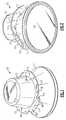
- Figs. 1-3illustrate a light engine 10 in accordance with the present inventive subject matter.
- Fig. 1is a first perspective view of the light engine 10.
- Fig. 2is a second perspective view of the light engine 10.
- Fig. 3is a sectional view of the light engine 10.
- the light engine 10comprises a light engine housing that comprises a mixing chamber element 11, a driver chamber element 12 and a connection element 13. Any of these elements (i.e., the mixing chamber element 11, the driver chamber element 12 and the connection element 13 ) can be provided in two or more pieces if desired, rather than as a unitary structure.
- the light engine housingcan be a single unitary structure, or can comprise two or more structures, e.g., (1) the mixing chamber element 11, the driver chamber element 12 and the connection element 13 can each be separate structures that are attached to one another, (2) the mixing chamber element 11 and the driver chamber element 12 can be a unitary structure (i.e., the mixing chamber element 11 and the driver chamber element 12 can be integral) and the connection element 13 can be a separate structure attached to the integral mixing chamber element 11 and driver chamber element 12, (3) the mixing chamber element 11, the driver chamber element 12 and the connection element 13 can all be included in a unitary structure (i.e., the mixing chamber element 11, the driver chamber element 12 and the connection element 13 can be a single integral structure), etc.
- the mixing chamber element 11, the driver chamber element 12 and the connection element 13can each be separate structures that are attached to one another
- the mixing chamber element 11 and the driver chamber element 12can be a unitary structure (i.e., the mixing chamber element 11 and the driver chamber element 12 can be integral)
- the connection element 13can be
- the light engine 10also comprises a plurality of light emitting diodes 14 (see Fig. 3 )
- the light emitting diodes 14can include a plurality of light emitting diodes that emit blue light (at least some of which are packaged with luminescent material that emits greenish-yellowish light) and a plurality of light emitting diodes that emit red light.
- the light engine 10also comprises a lens 15.
- the mixing chamber element 11defines a mixing chamber 16 in which light emitted by the light emitting diodes 14 mixes prior to exiting the light engine housing 10.
- connection element 13has a plurality of mounting surfaces 17 (see Figs. 1 and 2 ), e.g., top and bottom surfaces and front and back surfaces, any or all of which can be used to connect to other modules or elements. As can be seen in Figs. 1 and 2 , there are many pairs of mounting surfaces 17 that are not parallel to one another.
- the connection element 13also has a plurality of apertures 18 that have respective axes, some of which extend in directions that differ from the directions in which the axes of other apertures 18 extend, some of which are substantially parallel to or perpendicular to the axis 19 of the light engine housing 10.
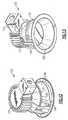
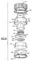
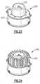
- Figs. 4-6illustrate a downlight 40 in accordance with the present inventive subject matter, for use in, e.g., a ceiling recessed downlight with spinning trim.
- Fig. 4is a sectional view of the downlight 40.
- Fig. 5is a first perspective view of the downlight 40.
- Fig. 6is a second perspective view of the downlight 40.
- the light engine in the downlight 40 depicted in Figs. 4-6comprises a light engine housing that comprises a mixing chamber element 41, a driver chamber element 42 and a connection element 43.
- the light engine in the downlight 40 depicted in Figs. 4-6is similar to the light engine 10 depicted in Figs. 1-3 , except that a trim element 44 is attached to the connection element 43, and there is provided an electrical connector 45 in the form of a wire that can be connected to a terminal, another wire, or any other kind of electrical connector.
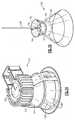
- Figs. 7-8illustrate a downlight 70 in accordance with the present inventive subject matter, for use in, e.g., a ceiling recessed downlight with an extrusion heat sink.
- Fig. 7is a first perspective view of the downlight 70
- Fig. 8is a second perspective view of the downlight 70.
- the light engine in the downlight 70 depicted in Figs. 7-8comprises a light engine housing that comprises a mixing chamber element 71, a driver chamber element 72 and a connection element 73.
- the light engine in the downlight 70 depicted in Figs. 7-8is similar to the light engine 10 depicted in Figs. 1-3 , except that a heat sink element 74 is attached to the connection element 73, and there is provided an electrical connector 75 in the form of a wire that can be connected to a terminal, another wire, or any other kind of electrical connector.
- the light engineis shown in Figs. 7-8 in position to be attached to a trim element 78 that comprises clamps 76 and a rim 77 that can engage the mixing chamber element 71 .
- Figs. 9-11illustrate a track head 90 in accordance with the present inventive subject matter.
- Fig. 9is a view, partially in phantom, showing the exterior as well as part of the interior, of the track head 90.
- Fig. 10is a first perspective view of the track head 90.
- Fig. 11is a second perspective view of the track head 90.
- the light engine in the track head 90 depicted in Figs. 9-11comprises a light engine housing that comprises a mixing chamber element 91, a driver chamber element 92 and a connection element 93.
- the light engine in the track head 90 depicted in Figs. 9-11is similar to the light engine 10 depicted in Figs. 1-3 , except that a fixture housing 94 is attached to the connection element 93, a bracket 95 is attached to the fixture housing 94 and an electrical connector sleeve 96 is connected to the driver chamber element 92.
- Figs. 12-14illustrate a downlight 120 in accordance with the present inventive subject matter, for use in, e.g., a low-profile ceiling recessed downlight.
- Fig. 12is a first perspective view of the downlight 120.
- Fig. 13is a second perspective view of the downlight 120.
- Fig. 14is a view, partially in phantom, showing the exterior as well as part of the interior, of the downlight 120.
- the light engine in the downlight 120 depicted in Figs. 12-14comprises a light engine housing that comprises a mixing chamber element 121, a driver chamber element 122 and a connection element 123.
- the light engine in the downlight 120 depicted in Figs. 12-14is similar to the light engine 10 depicted in Figs. 1-3 , except that a heatsink 124 that encloses a power supply and provides an enclosed cavity for a /junction box is attached to the connection element 123, and a trim element 128 is attached to the mixing chamber element 121 with clamps 126 and a rim 127.
- Figs. 15-17illustrate a ceiling pendant light 150 in accordance with the present inventive subject matter.
- Fig. 15is a view, partially in phantom, showing the exterior as well as part of the interior, of the pendant light 150.
- Fig. 16is a first perspective view of the pendant light 150.
- Fig. 17is a second perspective view of the pendant light 150.
- the light engine in the pendant light 150 depicted in Figs. 15-17comprises a light engine housing that comprises a mixing chamber element 151, a driver chamber element 152 and a connection element 153.
- the light engine in the pendant light 150 depicted in Figs. 15-17is similar to the light engine 10 depicted in Figs. 1-3 , except that a trim element 154 is attached to the connection element 153, and there is provided an electrical connector 155 in the form of a wire that can be connected to, e.g., another wire, inside a pendant mount 159 (or that can be connected to a pendant cord).
- light engines according to the present inventive subject mattercan readily be attached to a variety of modules in order to build a variety of lighting devices, e.g., various downlights, track lighting devices, pendants lights, etc.
- any other suitable modulescan be connected to the light engines according to the present inventive subject matter in order to build any other desired lighting device, e.g., a ceiling surface (surface mount) lighting device, a wall surface (single wall mount) lighting device, a pole light, or any other conventional or unconventional lighting device.
- FIG. 18is a schematic drawing depicting a variety of mounting locations, including two ceiling surface locations 181 (one covered, one not covered), a ceiling pendant location 182, two ceiling-recessed locations 183 (one covered, one not covered), two wall surface locations 184 (one above 1.2 meters on the wall, one below 1.2 meters on the wall), two wall-recessed locations 185 (one above 1.2 meters on the wall, one below 1.2 meters on the wall), a ground-mounted surface location 186, a pole or post location 187, an overhead location 188, and a ground-mounted recessed location 189.
- a wall surface (single wall mount) lighting devicecan be installed in the upper location 184; a ceiling surface (surface mount) lighting device can be installed in the locations 181; a ceiling pendant lighting device can be installed in the location 182; a ceiling recessed downlight can be installed in the locations 183; a pole light can be installed in the location 187, etc.
- Figs. 19-22illustrate a lighting device 190 in accordance with the present inventive subject matter.
- Fig. 19is a perspective view of the lighting device 190.
- Fig. 20is a front view of the lighting device 190.
- Fig. 21is a sectional view of the lighting device 190, taken along the plane 21-21 shown in Fig. 20 .
- Fig. 22is an exploded view of the lighting device 190 .
- the lighting device 190comprises a light engine and a heat sink element 191.
- the light engine in the lighting device 190comprises a light engine housing 192 and a connection element 193.
- the light engine in the lighting device 190can further comprise an isolation cup 194, a power supply / driver / circuit board module 195, an insulating sheet 196, a heat spreader 197, a solid state light emitter / circuit board module 198, a reflector 199, a combination lens and diffuser 200 and a lens retainer 201.
- the light engine housing 192comprises a driver chamber element 202 and a mixing chamber element 203.
- the driver chamber element 202 and the mixing chamber element 203are a single unitary structure, i.e., the driver chamber element 202 and the mixing chamber element 203 are integral.
- the driver chamber element 202 and the mixing chamber element 203being a single unitary structure, heat can pass from a location on the driver chamber element 202 to a location on the mixing chamber element 203 without having to cross an interface between two separate structures, so that such heat transfer is less impeded.
- the driver chamber element 202 and the mixing chamber element 203being a single unitary structure, the power supply / driver / circuit board module 195 and the solid state light emitter / circuit board module 198 are enclosed within the light engine housing 192 (which can be made of metal (e.g., aluminum), plastic, or any other suitable material or materials), which can provide necessary or desired flame-proof properties (without there being any interface between separate structures (i.e., structures that are separate, even though they might be in contact) which might otherwise detract from (or in some cases vitiate) flame-proof properties).
- the light engine housing 192which can be made of metal (e.g., aluminum), plastic, or any other suitable material or materials), which can provide necessary or desired flame-proof properties (without there being any interface between separate structures (i.e., structures that are separate, even though they might be in contact) which might otherwise detract from (or in some cases vitiate) flame-proof properties).
- the longitudinal profile of the mixing chamber element 203is somewhat curved, whereas the longitudinal profile of the reflector 199 is substantially straight, whereby the mixing chamber element 203 has somewhat more surface area than it would have if it were substantially straight.
- An isolation cup 194if included, provides electrical isolation of the power supply from the light engine housing 192.
- the isolation cup 194can be made of any suitable electrically insulating material.
- the insulating sheet 196can be made of any suitable electrically insulating material (e.g., a flame-proof material such as Formex or insulation tape).
- the insulating sheet 196can have holes that are aligned with transistors (e.g., FETs) in the power supply / driver / circuit board module 195 and/or with any other component of the power supply / driver / circuit board module 195 for which significant heat removal is needed (or, e.g., increased heat removal is desired) so that such transistors or components can directly contact the heat spreader 197 (or can at least more readily transfer heat to the heat spreader 197 ).
- the power supply / driver / circuit board module 195can fit inside the isolation cup 194, which in turn can fit inside the driver chamber element 202.
- the heat spreader 197can be made of any suitable material that provides good heat conductivity, e.g., materials selected from among metals (e.g., aluminum), metal alloys, ceramics, and polymers mixed with ceramic or metal or metalloid particles.
- the heat spreader 197passes heat from the solid state light emitter / circuit board module 198 to the light engine housing 192, from which it can pass to the mixing chamber element 203, the driver chamber element 202, the connection element 193 and/or the heat sink element 191, i.e., in either direction (up or down in the orientation depicted in Figs. 20 and 21 ) relative to the heat spreader 197.
- the heat spreader 197can have one or more mounting posts 204 (see Fig.
- the insulating sheet 196can be in contact with the heat spreader 197, e.g., it can be flush with the heat spreader 197.
- the reflector 199can be made of any suitable material or materials (as noted above in the discussion of materials out of which a reflector which is part of a mixing chamber element can be made).
- the reflector 199can fit inside the mixing chamber element 203.
- the combination lens and diffuser 200can be any suitable lens, diffuser or lens / diffuser combination.
- the lens retainer 201holds the combination lens and diffuser 200 in place relative to the light engine housing 192, and can include tabs 205 that have projections that fit into apertures 206 in the light engine housing 192 (or into recesses in the light engine housing 192 that do not extend completely through the light engine housing 192 ). Instead of or in addition to the tabs 205, the lens retainer 201 can be attached to the light engine housing 192 in any suitable way (e.g., using screws that extend through the lens retainer 201 and into the light engine housing 192).
- the heat spreader 197can have tabs 207 that extend through openings 208 in the light engine housing 192 in order to hold the heat spreader 197, the insulating sheet 196, the power supply / driver / circuit board module 195 and the isolation cup 194 in place relative to the light engine housing 192.
- Screwscan be threaded through holes in the connection element 193 and into the heat spreader 197 to secure the heat spreader 197 relative to the connection element 193 (as well as the light engine housing 192 ) (or other attachment devices or materials, e.g., bolts, rivets, staples, adhesive, etc. can be used in place of such screws), whereby the light engine housing 192 can be sandwiched between the connection element 193 and the heat spreader 197.
- the outer edge of the heat spreader 197can be in contact with the ledge formed by the region of the light engine housing 192 extending between the smaller-diameter lower (in the orientation depicted in Figs. 20-21 ) portion of the driver chamber element 202 and the larger-diameter upper portion of the mixing chamber element 203.
- Fig. 23illustrates a light engine 230.
- the light enginecomprises a connection element 231 and a light engine housing that comprises a driver chamber element 232 and a mixing chamber element 233.
- the driver chamber element 232 and the mixing chamber element 233are a single unitary structure, i.e., the driver chamber element 232 and the mixing chamber element 233 are integral.
- Fig. 24illustrates a lighting device 240 in accordance with the present inventive subject matter.
- the lighting device 240comprises a light engine as illustrated in Fig. 23 and a heat sink element 241.
- the heat sink element 241is attached to the connection element of the light engine.
- the solid state light emitteror one or more of the solid state light emitters, can be mounted directly on a mixing chamber element, if included, and/or on a trim element, if included.
- powercan be delivered to the solid state light emitter or solid state light emitters that is/are mounted directly on the mixing chamber element and/or on the trim element in any suitable way, e.g., through conductive traces provided on the mixing chamber element and/or on the trim element, through wires connected to one or more circuit boards, through traces embedded in the mixing chamber element and/or the trim element, through contacts that extend through the mixing chamber element and/or the trim element, etc.
- Mounting solid state light emitters directly on a mixing chamber element and/or on a trim elementcan reduce or minimize the thermal interfaces between the solid state light emitters and the ambient environment where the mixing chamber element and/or trim element acts as a heat sink for the solid state light emitters and is exposed to a room.
- Mounting solid state light emitters directly on a mixing chamber element and/or on a trim elementcan also eliminate the cost of a metal core circuit board.
- one or more solid state light emitterscould be mounted on a circuit board (e.g., a metal core circuit board) that is mounted on a mixing chamber element and/or on a trim element.
- one or more thermal elementcan be provided that is on the mixing chamber element in a location where it can serve a specific solid state light emitter or group of solid state light emitters.
- a representative example of a suitable thermal elementis a projection that extends from the side of a mixing chamber element that is opposite the side on which the solid state light emitter(s) is/are mounted.
- a portion of the heat sink adjacent to the solid state light emitter (or solid state light emitters)can be removed (and optionally filled with a thermal element or a part of a thermal element).
- a thermal elementcan be made of any suitable material, and can be of any suitable shape.
- thermal element(s)Use of materials having higher heat conductivity in making the thermal element(s) generally provides greater heat transfer, and use of thermal element(s) of larger surface area and/or cross-sectional area generally provides greater heat transfer.
- Any two or more structural parts of the light engines described hereincan be integrated. Any structural part of the light engines described herein can be provided in two or more parts (which may be held together in any known way, e.g., with adhesive, screws, bolts, rivets, staples, etc.).
Landscapes
- Engineering & Computer Science (AREA)
- General Engineering & Computer Science (AREA)
- Non-Portable Lighting Devices Or Systems Thereof (AREA)
- Arrangement Of Elements, Cooling, Sealing, Or The Like Of Lighting Devices (AREA)
Description
- The present inventive subject matter is directed to light engines. In some aspects, the present inventive subject matter is directed to light engines that comprise one or more solid state light emitters, e.g., one or more light emitting diodes.
- There is an ongoing effort to develop systems that are more energy-efficient. A large proportion (some estimates are as high as twenty-five percent) of the electricity generated in the United States each year goes to lighting, a large portion of which is general illumination (e.g., downlights, flood lights, spotlights and other general residential or commercial illumination products). Accordingly, there is an ongoing need to provide lighting that is more energy-efficient.
- Solid state light emitters (e.g., light emitting diodes) are receiving much attention due to their energy efficiency. It is well known that incandescent light bulbs are very energy-inefficient light sources - about ninety percent of the electricity they consume is released as heat rather than light. Fluorescent light bulbs are more efficient than incandescent light bulbs (by a factor of about 10) but are still less efficient than solid state light emitters, such as light emitting diodes.
- In addition, as compared to the normal lifetimes of solid state light emitters, e.g., light emitting diodes, incandescent light bulbs have relatively short lifetimes, i.e., typically about 750-1000 hours. In comparison, light emitting diodes, for example, have typical lifetimes between 50,000 and 70,000 hours. Fluorescent bulbs generally have lifetimes (e.g., 10,000 - 20,000 hours) that are longer than those of incandescent lights, but they typically provide less favorable color reproduction. The typical lifetime of conventional fixtures is about 20 years, corresponding to a light-producing device usage of at least about 44,000 hours (based on usage of 6 hours per day for 20 years). Where the light-producing device lifetime of the light emitter is less than the lifetime of the fixture, the need for periodic change-outs is presented. The impact of the need to replace light emitters is particularly pronounced where access is difficult (e.g., vaulted ceilings, bridges, high buildings, highway tunnels) and/or where change-out costs are extremely high.
- There are a number of challenges presented with using light emitting diodes in lighting devices. In many cases, additional components are added to the lighting devices in order to address these challenges. It would be desirable to provide a light engine that comprises one or more solid state light emitters, in which such challenges are addressed and yet the light engine (or lighting device that includes the light engine) can fit within the same or substantially the same space that is provided for comparable conventional lighting devices (e.g., lighting devices that include one or more incandescent light sources and/or one or more fluorescent light sources). The ability for the light engine (or lighting device that includes the light engine) to fit in a space that is similar to (or identical to) a space into which conventional devices can fit is important when retro-fitting a lighting device, as well when installing a light engine (or lighting device that includes the light engine) in new construction.
- One such challenge results from the fact that the emission spectrum of any particular light emitting diode is typically concentrated around a single wavelength (as dictated by the light emitting diode's composition and structure), which is desirable for some applications, but not desirable for others, (e.g., for providing general illumination, such an emission spectrum generally does not provide light that appears white, and/or provides a very low CRI). As a result, in many cases (e.g., to make devices that emit light perceived as white or near-white, or to make devices that emit light that is not highly saturated) it is necessary to employ light sources (e.g., one or more solid state light emitters and optionally also one or more other types of light sources, e.g., additional light emitting diodes, luminescent materials, incandescent lights, etc.) that emit light of different colors. There are a variety of reasons that one or more solid state light emitters might cease emitting light and/or vary in their intensity of light emission, which can throw off the balance of color output and cause the lighting device to emit light that is perceived as being of a color that differs from the desired color of light output. As a result, in many of such devices, one challenge that necessitates the inclusion of additional components is that there may be a desire to provide additional circuitry that can adjust the current supplied to respective solid state light emitters (and/or other light emitters) in order to maintain the balance of color output among the light emitters that emit light of different colors in order to achieve the desired color output. Another such challenge is that there may be a desire to mix the light of different colors emitted from the different solid state light emitters by providing additional structure to assist in such mixing.
- One example of a reason that one or more solid state light emitters might vary in their intensity of light emission is temperature change (resulting, e.g., from change in ambient temperature and/or heating up of the solid state light emitters). Some types of solid state light emitters (e.g., solid state light emitters that emit light of different colors) experience differences in intensity of light emission (if supplied with the same current) at different temperatures, and frequently such changes in intensity occur to differing extents for emitters that emit light of different colors as temperature changes. For example, some light emitting diodes that emit red light have a very strong temperature dependence in at least some temperature ranges (e.g., AlInGaP light emitting diodes can reduce in optical output by ~ 20 % when heated up by ~ 40 degrees C, that is, approximately -0.5 % per degree C; some blue light emitting InGaN + YAG:Ce light emitting diodes can reduce in optical output by about - 0.15 % / degree C).
- Another example of a reason that one or more solid state light emitters might vary in their intensity of light emission is aging. Some solid state light emitters (e.g., solid state light emitters that emit light of different colors) experience decreases in intensity of light emission (if supplied with the same current) as they age, and frequently such decreases in intensity occur at differing rates.
- Another example of a reason that one or more solid state light emitters might vary in their intensity of light emission is damage to the solid state light emitter(s) and/or damage to circuitry that supplies current to the solid state light emitter(s).
- Another challenge presented in making a lighting device with light emitting diodes, that often necessitates the inclusion of additional components, is that the performance of many solid state light emitters may be reduced when they are subjected to elevated temperatures. For example, many light emitting diode light sources have average operating lifetimes of decades as opposed to just months or 1-2 years for many incandescent bulbs, but some light emitting diodes' lifetimes can be significantly shortened if they are operated at elevated temperatures. A common manufacturer recommendation is that the junction temperature of a light emitting diode should not exceed 85 degrees C if a long lifetime is desired. There may be a desire to counteract such problems, in many instances, by providing additional structure (or structures) to provide a desired degree of heat dissipation.
- Another challenge presented in making a lighting device with light emitting diodes, that often necessitates the inclusion of additional components, arises from the relatively high light output from a relatively small area provided by solid state emitters. Such a concentration of light output may present challenges in providing solid state lighting systems for general illumination in that, in general, a large difference in brightness in a small area may be perceived as glare and may be distracting to occupants. In many instances, therefore, there is a desire to provide additional structure to assist in mixing the emitted light and/or creating the perception that the emitted light is output through a larger area.
- Another challenge presented in making a lighting device with light emitting diodes, that often necessitates the inclusion of additional components, is that light emitting diodes are typically run most effectively on low voltage DC current, while line voltage is typically much higher voltage AC current. As a result, there is often a desire to provide circuitry that converts line voltage, e.g., from AC to DC and/or that reduces voltage.
- In addition, in some circumstances, there is a desire either to retrofit or install a lighting device in a circuit that has a conventional dimmer. Some dimmers operate based on signals contained in the current supplied to the lighting device (for example, duty cycle of an AC signal, e.g., from a triac), for which additional circuitry is generally needed.
- It would be desirable to be able to make a variety of lighting devices that include different numbers of solid state light emitters, and thereby generate heat at a variety of different rates, and to make it possible to easily provide heat dissipation systems that are suited to each of such a variety of lighting devices. It would be desirable to provide lighting devices in which the amount of heat that can be dissipated can be selected to match the rate of heat generation by each individual lighting device. For example, persons of skill in the art can readily envision a series of lighting devices in which each member of the series has a different number of light emitting diodes, resulting in respective different rates of heat generation. It would be desirable to be able to provide device by which incrementally different rates of heat dissipation in such respective devices could be interchangeably provided.
- There exist conventional lighting devices that have a wide variety of trim structures and/or fixture element structures. It would be desirable to be able to easily make a variety of solid state light emitter lighting devices (i.e., lighting devices that comprise one or more solid state light emitters) that include different types of trim structures and/or housing structures.
- There exist conventional lighting devices that have light intensity outputs and/or power inputs that would require a wide variety of circuitry in order to provide equivalent output from a lighting device comprising one or more solid state light emitters, and it would be desirable to be able to easily make a variety of solid state light emitter lighting devices that can provide such light intensity outputs and/or that can be powered by such power inputs.
- In some aspects, the present inventive subject matter provides light engines (and lighting devices that comprise such light engines) that can provide such features.
- In accordance with one aspect of the present inventive subject matter, there are provided light engines for lighting devices, in which the light engines can readily be interchangeably combined with one or more of a wide variety of heat sink modules, one or more of a wide variety of power supply modules, and/or one or more of a wide variety of driver modules that allow for adjustability depending on the desired application for the lighting device.
- In accordance with another aspect of the present inventive subject matter, there are provided light engines that each comprise a light engine housing, and a modular mixing chamber element (i.e., a mixing chamber module) and/or a modular driver chamber element (i.e., a driver chamber module), whereby the light engine housing can readily be interchangeably combined with one or more of a wide variety of mixing chamber elements, and/or one or more of a wide variety of driver chamber elements, in order to provide a lighting device or light engine that can accommodate the components needed for the lighting device (or a lighting device that includes the light engine) to satisfy the needs for a particular application (or in order to provide the components needed).
- In accordance with another aspect of the present inventive subject matter, there are provided light engines that each comprise a light engine housing, and a mixing chamber element that is removably attached to the light engine housing and/or a driver chamber element that is removably attached to the light engine housing. By providing a mixing chamber element that is removable and/or a driver chamber element that is removable, one or more of a wide variety of mixing chamber elements, and/or one or more of a wide variety of driver chamber elements can readily be interchanged (i.e., can be selectively combined with the light engine or the lighting device) in order to accommodate the components needed for a particular application (or in order to provide the components needed for such application).
- In some embodiments according to the present inventive subject matter, there are provided light engines for lighting devices, in which the light engines can readily be interchangeably combined with one or more trim elements and/or one or more fixture elements (and optionally also one or more heat sink modules, one or more power supply modules, and/or one or more driver modules, as mentioned above).
- In one aspect of the present inventive subject matter, there is provided a light engine comprising a light engine housing that comprises at least a first connection element. In some embodiments, the light engine housing further comprises a mixing chamber element and/or a driver chamber element. In some embodiments in which the light engine housing further comprises a mixing chamber element, the mixing chamber element at least in part defining a mixing chamber. In some embodiments, the connection element provides both mechanical connection and thermal coupling between the light engine housing and at least one other component, e.g., a mixing chamber element, a driver chamber element, a fixture housing, a trim element and/or a heat sink module.
- In another aspect of the present inventive subject matter, there is provided a light engine comprising a light engine housing to which a variety of mixing chamber elements can be interchangeably connected and/or to which a variety of driver chamber elements can be interchangeably connected (and/or in which a variety of mixing chamber elements can be interchangeably positioned and/or in which a variety of driver chamber elements can be interchangeably positioned).
- In another aspect of the present inventive subject matter, there is provided a light engine comprising a light engine housing and at least one light source (e.g., a solid state light emitter),
the light engine housing comprising a mixing chamber element, a driver chamber element and at least a first connection element, and
the mixing chamber element at least in part defining a mixing chamber in which light from the at least one light source mixes prior to exiting the light engine housing. - In some embodiments according to the present inventive subject matter, which can include or not include any of the features described herein, there is provided a lighting device that comprises a light engine as described herein, and the lighting device can further comprise at least one fixture element, at least one trim element, and/or at least one heat sink module. In some of such embodiments, the fixture element(s), the trim element(s), and/or the heat sink module(s), or any combination thereof, is/are attached to a connection element or to respective connection elements.
- In some embodiments according to the present inventive subject matter, which can include or not include any of the features described herein, the first connection element has at least first and second apertures, the first aperture has an axis that extends in a first direction, and the second aperture has an axis that extends in a second direction, the first direction differing from the second direction. In some of such embodiments, at least one of the axis of the first aperture and the axis of the second apertures is substantially parallel to an axis of the light engine housing, and/or at least one of the axis of the first aperture and the axis of the second apertures is substantially perpendicular to an axis of the light engine housing.
- In some embodiments according to the present inventive subject matter, which can include or not include any of the features described herein, the first connection element has at least first and second mounting surfaces, and the first mounting surface and the second mounting surface are not parallel. In some of such embodiments:
- at least one of the first and second mounting surfaces defines a plane with respect to which an axis of the light engine housing is substantially parallel,
- at least one of the first and second mounting surfaces defines a plane that is substantially perpendicular to an axis of the light engine housing, and/or
- at least a first aperture is formed in the first mounting surface and at least a second aperture is formed in the second mounting surface, the first aperture having an axis that extends in a first direction, the second aperture having an axis that extends in a second direction, the first direction differing from the second direction.
- In some embodiments according to the present inventive subject matter, which can include or not include any of the features described herein, there is provided a lighting device that comprises a light engine as described herein, and the lighting device can further comprise at least one component selected from among driver components and power supply components. In some of such embodiments, the at least one component selected from among driver components and power supply components is/are positioned within the driver chamber element.
- In some embodiments according to the present inventive subject matter, which can include or not include any of the features described herein, there is provided a lighting device that comprises a light engine as described herein, and the lighting device can further comprise at least one electrical connector.
- The inventive subject matter may be more fully understood with reference to the accompanying drawings and the following detailed description of the inventive subject matter.
Fig. 1 is a first perspective view of alight engine 10.Fig. 2 is a second perspective view of thelight engine 10.Fig. 3 is a sectional view of thelight engine 10.Fig. 4 is a sectional view of adownlight 40.Fig. 5 is a first perspective view of thedownlight 40.Fig. 6 is a second perspective view of thedownlight 40.Fig. 7 is a first perspective view of adownlight 70Fig. 8 is a second perspective view of thedownlight 70.Fig. 9 is a view, partially in phantom, showing the exterior as well as part of the interior, of atrack head 90.Fig. 10 is a first perspective view of thetrack head 90.Fig. 11 is a second perspective view of thetrack head 90.Fig. 12 is a first perspective view of adownlight 120.Fig. 13 is a second perspective view of thedownlight 120.Fig. 14 is a view, partially in phantom, showing the exterior as well as part of the interior, of thedownlight 120.Fig. 15 is a view, partially in phantom, showing the exterior as well as part of the interior, of aceiling pendant light 150.Fig. 16 is a first perspective view of theceiling pendant light 150.Fig. 17 is a second perspective view of theceiling pendant light 150.Fig. 18 is a schematic drawing depicting a variety of mounting locations.Fig. 19 is a perspective view of alighting device 190.Fig. 20 is a front view of thelighting device 190.Fig. 21 is a sectional view of thelighting device 190, taken along the plane21-21 shown inFig. 20 .Fig. 22 is an exploded view of thelighting device 190.Fig. 23 is a perspective view of alight engine 230.Fig. 24 is a perspective view of alighting device 240.- The present inventive subject matter now will be described more fully hereinafter with reference to the accompanying drawings, in which embodiments of the inventive subject matter are shown. However, this inventive subject matter should not be construed as being limited to the embodiments set forth herein. Rather, these embodiments are provided so that this disclosure will be thorough and complete, and will fully convey the scope of the inventive subject matter to those skilled in the art. Like numbers refer to like elements throughout. As used herein the term "and/or" includes any and all combinations of one or more of the associated listed items.
- The terminology used herein is for the purpose of describing particular embodiments only and is not intended to be limiting of the inventive subject matter. As used herein, the singular forms "a", "an" and "the" are intended to include the plural forms as well, unless the context clearly indicates otherwise. It will be further understood that the terms "comprises" and/or "comprising," when used in this specification, specify the presence of stated features, integers, steps, operations, elements, and/or components, but do not preclude the presence or addition of one or more other features, integers, steps, operations, elements, components, and/or groups thereof.
- When an element such as a layer, region or substrate is referred to herein as being "on", being mounted "on" or extending "onto" another element, it can be directly on or extend directly onto the other element or intervening elements may also be present. In contrast, when an element is referred to herein as being "directly on" or extending "directly onto" another element, there are no intervening elements present. Also, when an element is referred to herein as being "connected" or "coupled" to another element, it can be directly connected or coupled to the other element or intervening elements may be present. In contrast, when an element is referred to herein as being "directly connected" or "directly coupled" to another element, there are no intervening elements present. In addition, a statement that a first element is "on" a second element is synonymous with a statement that the second element is "on" the first element.
- The expression "in contact with", as used herein, means that the first structure that is in contact with a second structure is in direct contact with the second structure or is in indirect contact with the second structure. The expression "in indirect contact with" means that the first structure is not in direct contact with the second structure, but that there are a plurality of structures (including the first and second structures), and each of the plurality of structures is in direct contact with at least one other of the plurality of structures (e.g., the first and second structures are in a stack and are separated by one or more intervening layers). The expression "direct contact", as used in the present specification, means that the first structure which is "in direct contact" with a second structure is touching the second structure and there are no intervening structures between the first and second structures at least at some location.
- A statement herein that two components in a device are "electrically connected," means that there are no components electrically between the components that affect the function or functions provided by the device. For example, two components can be referred to as being electrically connected, even though they may have a small resistor between them which does not materially affect the function or functions provided by the device (indeed, a wire connecting two components can be thought of as a small resistor); likewise, two components can be referred to as being electrically connected, even though they may have an additional electrical component between them which allows the device to perform an additional function, while not materially affecting the function or functions provided by a device which is identical except for not including the additional component; similarly, two components which are directly connected to each other, or which are directly connected to opposite ends of a wire or a trace on a circuit board, are electrically connected. A statement herein that two components in a device are "electrically connected" is distinguishable from a statement that the two components are "directly electrically connected", which means that there are no components electrically between the two components.
- Although the terms "first", "second", etc. may be used herein to describe various elements, components, regions, layers, sections and/or parameters, these elements, components, regions, layers, sections and/or parameters should not be limited by these terms. These terms are only used to distinguish one element, component, region, layer or section from another region, layer or section. Thus, a first element, component, region, layer or section discussed below could be termed a second element, component, region, layer or section without departing from the teachings of the present inventive subject matter.
- Relative terms, such as "lower", "bottom", "below", "upper", "top" or "above," may be used herein to describe one element's relationship to another elements as illustrated in the Figures. Such relative terms are intended to encompass different orientations of the device in addition to the orientation depicted in the Figures. For example, if the device in the Figures is turned over, elements described as being on the "lower" side of other elements would then be oriented on "upper" sides of the other elements. The exemplary term "lower", can therefore, encompass both an orientation of "lower" and "upper," depending on the particular orientation of the figure. Similarly, if the device in one of the figures is turned over, elements described as "below" or "beneath" other elements would then be oriented "above" the other elements. The exemplary terms "below" or "beneath" can, therefore, encompass both an orientation of above and below.
- The expression "illumination" (or "illuminated"), as used herein when referring to a solid state light emitter, means that at least some current is being supplied to the solid state light emitter to cause the solid state light emitter to emit at least some electromagnetic radiation (e.g., visible light). The expression "illuminated" encompasses situations where the solid state light emitter emits electromagnetic radiation continuously, or intermittently at a rate such that a human eye would perceive it as emitting electromagnetic radiation continuously or intermittently, or where a plurality of solid state light emitters of the same color or different colors are emitting electromagnetic radiation intermittently and/or alternatingly (with or without overlap in "on" times), e.g., in such a way that a human eye would perceive them as emitting light continuously or intermittently (and, in some cases where different colors are emitted, as separate colors or as a mixture of those colors).
- The expression "excited", as used herein when referring to luminescent material, means that at least some electromagnetic radiation (e.g., visible light, UV light or infrared light) is contacting the luminescent material, causing the luminescent material to emit at least some light. The expression "excited" encompasses situations where the luminescent material emits light continuously, or intermittently at a rate such that a human eye would perceive it as emitting light continuously or intermittently, or where a plurality of luminescent materials that emit light of the same color or different colors are emitting light intermittently and/or alternatingly (with or without overlap in "on" times) in such a way that a human eye would perceive them as emitting light continuously or intermittently (and, in some cases where different colors are emitted, as a mixture of those colors).
- The expression "the first direction differing from the second direction", e.g., as used in the expression "the first aperture having an axis that extends in a first direction, the second aperture having an axis that extends in a second direction, the first direction differing from the second direction" means that an axis of the first aperture and an axis of the second aperture are not identical or parallel.
- The expression "axis of the aperture" (and the like), as used herein, can refer to a straight line about which the aperture is substantially symmetrical. In instances where the aperture is not substantially symmetrical about any line, the expression "axis of the aperture" can refer to a line about which rotation of a uniform-density object that fills the aperture would be substantially balanced.
- The expression "substantially symmetrical", as used herein, when referring to a shape, means that the shape is symmetrical or could be made symmetrical by removing a specific region or regions which in total comprise not more than about 10 percent of its volume and/or by adding a specific region or regions which in total comprise not more than about 10 percent of its volume.
- The expression "substantially balanced", as used herein, when referring to a structure, means that the structure is balanced or could be balanced by adding to a specific location or locations mass that in total comprises not more than about 10 percent of the mass of the structure.
- The expression "the first mounting surface and the second mounting surface not being parallel", e.g., as used in the expression "the connection element having at least first and second mounting surfaces, the first mounting surface and the second mounting surface not being parallel" means that a first plane defined by the first mounting surface and a second plane defined by the second mounting surface are not parallel or substantially parallel (i.e., that the respective first and second planes do not diverge from each other by more than an angle of 5 degrees.
- The expression "first plane defined by the first mounting surface", means a plane in which at least 90% of the points in the first mounting surface are located on the plane or between the plane and a second plane that is spaced from the plane by a distance of not more than 5% of the largest dimension of the surface, and likewise for other similar expressions.
- The expression "substantially parallel" means that two lines (or two planes) do not diverge from each other by more than an angle of 5 degrees.
- The expression "substantially perpendicular", as used herein, means that at least 90% of the points in the structure which is characterized as being substantially perpendicular to a reference plane or line are located on one of or between a pair of planes (1) which are perpendicular to the reference plane, (2) which are parallel to each other and (3) which are spaced from each other by a distance of not more than 5% of the largest dimension of the structure.
- The expression "thermal coupling", as used herein, means that heat transfer occurs between (or among) the two (or more) items for which there is thermal coupling. Such heat transfer encompasses any and all types of heat transfer, regardless of how the heat is transferred between or among the items. That is, the heat transfer between (or among) items can be by conduction, convection, radiation, or any combinations thereof, and can be directly from one of the items to the other, or indirectly through one or more intervening elements or spaces (which can be solid, liquid and/or gaseous) of any shape, size and composition. The expression "thermal coupling" encompasses structures that are "adjacent" (as defined herein) to one another. In some situations / embodiments, the majority of the heat transferred from the light source is transferred by conduction; in other situations / embodiments, the majority of the heat that is transferred from the light source is transferred by convection; and in some situations / embodiments, the majority of the heat that is transferred from the light source is transferred by a combination of conduction and convection.
- The expression "adjacent", as used herein to refer to a spatial relationship between a first structure and a second structure, means that the first and second structures are next to each other. That is, where the structures that are described as being "adjacent" to one another are similar, no other similar structure is positioned between the first structure and the second structure (for example, where two dissipation elements are adjacent to each other, no other dissipation element is positioned between them). Where the structures that are described as being "adjacent" to one another are not similar, no other structure is positioned between them.
- The expression "lighting device", as used herein, is not limited, except that it indicates that the device is capable of emitting light. That is, a lighting device can be a device which illuminates an area or volume, e.g., a structure, a swimming pool or spa, a room, a warehouse, an indicator, a road, a parking lot, a vehicle, signage, e.g., road signs, a billboard, a ship, a toy, a mirror, a vessel, an electronic device, a boat, an aircraft, a stadium, a computer, a remote audio device, a remote video device, a cell phone, a tree, a window, an LCD display, a cave, a tunnel, a yard, a lamppost, or a device or array of devices that illuminate an enclosure, or a device that is used for edge or back-lighting (e.g., back light poster, signage, LCD displays), bulb replacements (e.g., for replacing AC incandescent lights, low voltage lights, fluorescent lights, etc.), lights used for outdoor lighting, lights used for security lighting, lights used for exterior residential lighting (wall mounts, post/column mounts), ceiling fxtures/wall sconces, under cabinet lighting, lamps (floor and/or table and/or desk), landscape lighting, track lighting, task lighting, specialty lighting, ceiling fan lighting, archival/art display lighting, high vibration/impact lighting - work lights, etc., mirrors/vanity lighting, or any other light emitting device.
- The present inventive subject matter further relates to an illuminated enclosure (the volume of which can be illuminated uniformly or non-uniformly), comprising an enclosed space and at least one light engine according to the present inventive subject matter, wherein the light engine illuminates at least a portion of the enclosed space (uniformly or non-uniformly).
- Some embodiments of the present inventive subject matter comprise at least a first power line, and some embodiments of the present inventive subject matter are directed to a structure comprising a surface and at least one light engine corresponding to any embodiment of a light engine according to the present inventive subject matter as described herein, wherein if current is supplied to the first power line, and/or if at least one solid state light emitter in the light engine is illuminated, the light engine would illuminate at least a portion of the surface.
- The present inventive subject matter is further directed to an illuminated area, comprising at least one item, e.g., selected from among the group consisting of a structure, a swimming pool or spa, a room, a warehouse, an indicator, a road, a parking lot, a vehicle, signage, e.g., road signs, a billboard, a ship, a toy, a mirror, a vessel, an electronic device, a boat, an aircraft, a stadium, a computer, a remote audio device, a remote video device, a cell phone, a tree, a window, an LCD display, a cave, a tunnel, a yard, a lamppost, etc., having mounted therein or thereon at least one light engine as described herein.
- Unless otherwise defined, all terms (including technical and scientific terms) used herein have the same meaning as commonly understood by one of ordinary skill in the art to which this inventive subject matter belongs. It will be further understood that terms, such as those defined in commonly used dictionaries, should be interpreted as having a meaning that is consistent with their meaning in the context of the relevant art and the present disclosure and will not be interpreted in an idealized or overly formal sense unless expressly so defined herein. It will also be appreciated by those of skill in the art that references to a structure or feature that is disposed "adjacent" another feature may have portions that overlap or underlie the adjacent feature.
- As noted above, in some aspects, the present inventive subject matter is directed to a light engine that comprises a light engine housing and at least one solid state light emitter, in which the light engine housing comprises at least one connection element, and in some embodiments, the light engine housing further comprises a mixing chamber element and/or a driver chamber element.
- Some or all of the one or more solid state light emitters can be provided in the light engine housing, e.g., in a mixing chamber element and/or in a driver chamber element.
- Persons of skill in the art are familiar with, and have ready access to, a wide variety of solid state light emitters, and any suitable solid state light emitter (or solid state light emitters) can be employed in the light engines according to the present inventive subject matter. A variety of solid state light emitters are well known, and any of such light emitters can be employed according to the present inventive subject matter. Representative examples of solid state light emitters include light emitting diodes (inorganic or organic, including polymer light emitting diodes (PLEDs)) with or without luminescent materials.
- Persons of skill in the art are familiar with, and have ready access to, a variety of solid state light emitters that emit light having a desired peak emission wavelength and/or dominant emission wavelength, and any of such solid state light emitters (discussed in more detail below), or any combinations of such solid state light emitters, can be employed in embodiments that comprise a solid state light emitter.
- Light emitting diodes are semiconductor devices that convert electrical current into light. A wide variety of light emitting diodes are used in increasingly diverse fields for an ever-expanding range of purposes. More specifically, light emitting diodes are semiconducting devices that emit light (ultraviolet, visible, or infrared) when a potential difference is applied across a p-n junction structure. There are a number of well known ways to make light emitting diodes and many associated structures, and the present inventive subject matter can employ any such devices.
- A light emitting diode produces light by exciting electrons across the band gap between a conduction band and a valence band of a semiconductor active (light-emitting) layer. The electron transition generates light at a wavelength that depends on the band gap. Thus, the color of the light (wavelength) (and/or the type of electromagnetic radiation, e.g., infrared light, visible light, ultraviolet light, near ultraviolet light, etc., and any combinations thereof) emitted by a light emitting diode depends on the semiconductor materials of the active layers of the light emitting diode.
- The expression "light emitting diode" is used herein to refer to the basic semiconductor diode structure (i.e., the chip). The commonly recognized and commercially available "LED" that is sold (for example) in electronics stores typically represents a "packaged" device made up of a number of parts. These packaged devices typically include a semiconductor based light emitting diode such as (but not limited to) those described in
U.S. Pat. Nos. 4,918,487 ;5,631,190 ; and5,912,477 ; various wire connections, and a package that encapsulates the light emitting diode. - Light engines according to the present inventive subject matter can, if desired, further comprise one or more luminescent materials.
- A luminescent material is a material that emits a responsive radiation (e.g., visible light) when excited by a source of exciting radiation. In many instances, the responsive radiation has a wavelength that is different from the wavelength of the exciting radiation.
- Luminescent materials can be categorized as being down-converting, i.e., a material that converts photons to a lower energy level (longer wavelength) or up-converting, i.e., a material that converts photons to a higher energy level (shorter wavelength).
- One type of luminescent material are phosphors, which are readily available and well known to persons of skill in the art. Other examples of luminescent materials include scintillators, day glow tapes and inks that glow in the visible spectrum upon illumination with ultraviolet light.
- Persons of skill in the art are familiar with, and have ready access to, a variety of luminescent materials that emit light having a desired peak emission wavelength and/or dominant emission wavelength, or a desired hue, and any of such luminescent materials, or any combinations of such luminescent materials, can be employed, if desired.
- The one or more luminescent materials can be provided in any suitable form. For example, the luminescent element can be embedded in a resin (i.e., a polymeric matrix), such as a silicone material, an epoxy material, a glass material or a metal oxide material, and/or can be applied to one or more surfaces of a resin, to provide a lumiphor.
- The one or more solid state light emitters (and optionally one or more luminescent materials) can be arranged in any suitable way.
- Representative examples of suitable solid state light emitters, including suitable light emitting diodes, luminescent materials, lumiphors, encapsulants, etc. that may be used in practicing the present inventive subject matter, are described in:
U.S. Patent Publication No. 2007/0236911, filed December 21, 2006 ;U.S. Patent Publication No. 2007/0170447, filed January 19, 2007 ;U.S. Patent Publication No. 2007/0274080, filed May 22, 2007 ;U.S. Patent Publication No. 2007/0280624, filed May 24, 2007 ;U.S. Patent Publication No. 2007/0274063, filed May 22. 2007 ;U.S. Patent Publication No. 2007/0278934, filed April 18, 2007 ;U.S. Patent Publication No. 2008/0106895, filed November 7, 2007 ;U.S. Patent Publication No. 2008/0084685, filed August 22, 2007 ;U.S. Patent No. 7,213,940, issued on May 8, 2007 ;U.S. Patent Publication No. 2008/0130285, filed on November 30, 2007 ;U.S. Patent Publication No. 2009-0296384, filed on June 1, 2009 ;U.S. Patent Publication No. 2008/0089053, filed October 11, 2007 ;U.S. Patent Publication No. 2008/0304261, filed May 8, 2008 ; andU.S. Patent Publication No. 2009/0108269, filed on January 22, 2008 .- In general, light of any number of colors can be mixed by the light engines according to the present inventive subject matter. Representative examples of blending of light colors are described in:
U.S. Patent Publication No. 2007/0139920, filed December 20, 2006 ;U.S. Patent Publication No. 2007/0137074, filed December 20, 2006 ;U.S. Patent Publication No. 2007/0278934, filed April 18, 2007 ;U.S. Patent Publication No. 2007/0267983, filed April 18, 2007 ;U.S. Patent Publication No. 2007/0278503, filed April 19, 2007 ;U.S. Patent Publication No. 2008/0106895, filed November 7, 2007 ;U.S. Patent Publication No. 2008/0304260, filed May 8, 2008 ;U.S. Patent Publication No. 2008/0278940, filed May 8, 2008 ;U.S. Patent Publication No. 2008/0278928, filed May 8, 2008 ;U.S. Patent No. 7,213,940, issued on May 8, 2007 ;U.S. Patent Publication No. 2008/0130285, filed on November 30, 2007 ;U.S. Patent Publication No. 2009-0296384, filed on June 1, 2009 ;U.S. Patent Publication No. 2009/0184616, filed on October 9, 2008 ;U.S. Patent Publication No. 2008/0136313, filed December 6, 2007 ;U.S. Patent Publication No. 2008/0259589, filed on February 22, 2008 ;U.S. Patent Publication No. 2008/0304261, filed May 8, 2008 ; andU.S. Patent No. 8,716,952, filed on August 4, 2009 .- A mixing chamber element (if included) can be of any suitable shape and size, and can be made of any suitable material or materials. Light emitted by the one or more solid state light emitters can be mixed to a suitable extent in a mixing chamber before exiting the light engine.
- Representative examples of materials that can be used for making a mixing chamber element include, among a wide variety of other materials, spun aluminum, stamped aluminum, die cast aluminum, rolled or stamped steel, hydroformed aluminum, injection molded metal, injection molded thermoplastic, compression molded or injection molded thermoset, molded glass, liquid crystal polymer, polyphenylene sulfide (PPS), clear or tinted acrylic (PMMA) sheet, cast or injection molded acrylic, thermoset bulk molded compound or other composite material. In some embodiments, a mixing chamber element can consist of or can comprise a reflective element (and/or one or more of its surfaces can be reflective). Such reflective elements (and surfaces) are well-known and readily available to persons skilled in the art. A representative example of a suitable material out of which a reflective element can be made is a material marketed by Furukawa (a Japanese corporation) under the trademark MCPET®.
- In some embodiments, a mixing chamber is defined (at least in part) by a mixing chamber element. In some embodiments, a mixing chamber is defined in part by a mixing chamber element (and/or by a trim element) and in part by a lens and/or a diffuser. The expression "defined (at least in part)", e.g., as used in the expression "mixing chamber is defined (at least in part) by a mixing chamber element" means that the element or feature that is defined "at least in part" by a particular structure is defined completely by that structure or is defined by that structure in combination with one or more additional structures.
- A driver chamber element (if included) can be of any suitable shape and size, and can be made of any suitable material or materials. In some embodiments, a driver chamber element (or at least a part thereof) can be made of the same material or materials as a mixing chamber element (or a portion thereof), and/or a driver chamber element (or at least a part thereof, e.g., a cover) can be made of plastic, glass, metal (optionally with one or more insulator), or a flame resistant fiber material. In some embodiments, a driver chamber element and a mixing chamber element are integral.
- In some embodiments, a driver chamber element is shaped so that it can accommodate any of a variety of driver modules and/or power supply modules (or one or more components thereof) involved in receiving current supplied to a lighting device, modifying the current (e.g., converting it from AC to DC and/or from one voltage to another voltage), and/or driving one or more solid state light emitters (e.g., illuminating one or more solid state light emitter intermittently and/or adjusting the current supplied to one or more solid state light emitters in response to a user command, a detected change in intensity or color of light output, a detected change in an ambient characteristic such as temperature or background light, etc., and/or a signal contained in the input power, such as a dimming signal in AC power supplied to the lighting device), e.g., any of the components discussed herein.
- In some embodiments according to the present inventive subject matter, there is provided a light engine in which one or more components are provided in a driver chamber element, as desired and/or as suitable. For example, a driver module (or at least a portion of a driver module) can be provided in a driver chamber element. A driver module can comprise any of (1) an electrical connector, for example, one or more wires (e.g., that can be connected to one or more wire-receiving elements or spliced to other wires), an Edison plug or GU24 pins, (2) one or more electrical components employed in converting electrical power (e.g., from AC to DC and/or from one voltage to another voltage), (3) one or more electrical components employed in driving one or more solid state light emitter, e.g., running one or more solid state light emitter intermittently and/or adjusting the current supplied to one or more solid state light emitters in response to a user command, a detected change in intensity or color of light output, a detected change in an ambient characteristic such as temperature or background light, etc., and/or a signal contained in the input power (e.g., a dimming signal in AC power supplied to the lighting device), etc., (4) one or more circuit boards (e.g., a metal core circuit board) for supporting and/or providing current to any electrical components, (5) one or more wires connecting any components (e.g., connecting an Edison plug to a circuit board), etc.
- Different driver modules and/or power supply modules can be provided that include any of such components selected and/or combined to be suitable to connect to any given power input and to drive any solid state light emitter or combination of solid state light emitters connected to each other in any way, and to drive the solid state light emitter or solid state light emitters in any suitable way.
- Any desired circuitry (including any desired electronic components) can be employed in order to supply energy to the one or more solid state light emitters according to the present inventive subject matter. Representative examples of circuitry which may be used in practicing the present inventive subject matter is described in:
U.S. Patent Publication No. 2007/0171145, filed January 24, 2007 ;U.S. Patent Publication No. 2007/0279440, filed May 30, 2007 ;U.S. Patent Publication No. 2008/0088248, filed September 13, 2007 ;U.S. Patent Publication No. 2008/0309255, filed May 8, 2008 ;U.S. Patent Publication No. 2009/0184666 , filed 12/4/08;U.S. Patent Publication No. 2009-0184662, filed on December 4, 2008 ;U.S. Patent No. 8,901,829, filed on September 24, 2009 ; and- U.S. Patent Publication No.
US 2011-0068702, filed on September 24, 2009 . - For example, solid state lighting systems have been developed that include a power supply that receives the AC line voltage and converts that voltage to a voltage (e.g., to DC and to a different voltage value) and/or current suitable for driving solid state light emitters. Typical power supplies for light emitting diode light sources include linear current regulated supplies and/or pulse width modulated current and/or voltage regulated supplies.
- Many different techniques have been described for driving solid state light sources in many different applications, including, for example, those described in United States Patent No.
3,755,697 to Miller , United States Patent No.5,345,167 to Hasegawa et al , United States Patent No.5,736,881 to Ortiz , United States Patent No.6,150,771 to Perry , United States Patent No.6,329,760 to Bebenroth , United States Patent No.6,873,203 to Latham, II et al , United States Patent No.5,151,679 to Dimmick , United States Patent No.4,717,868 to Peterson , United States Patent No.5,175,528 to Choi et al , United States Patent No.3,787,752 to Delay , United States Patent No.5,844,377 to Anderson et al , United States Patent No.6,285,139 to Ghanem , United States Patent No.6,161,910 to Reisenauer et al , United States Patent No.4,090,189 to Fisler , United States Patent No.6,636,003 to Rahm et al , United States Patent No.7,071,762 to Xu et al , United States Patent No.6,400,101 to Biebl et al , United States Patent No.6,586,890 to Min et al , United States Patent No.6,222,172 to Fossum et al , United States Patent No.5,912,568 to Kiley , United States Patent No.6,836,081 to Swanson et al , United States Patent No.6,987,787 to Mick , United States Patent No.7,119,498 to Baldwin et al , United States Patent No.6,747,420 to Barth et al , United States Patent No.6,808,287 to Lebens et al , United States Patent No.6,841,947 to Berg-johansen , United States Patent No.7,202,608 to Robinson et al , United States Patent No,6,995,518 , United States Patent No.6,724,376 , United States Patent No.7,180,487 to Kamikawa et al , United States Patent No.6,614,358 to Hutchison et al , United States Patent No.6,362,578 to Swanson et al , United States Patent No.5,661,645 to Hochstein , United States Patent No.6,528,954 to Lys et al , United States Patent No.6,340,868 to Lys et al , United States Patent No.7,038,399 to Lys et al , United States Patent No.6,577,072 to Saito et al , and United States Patent No.6,388,393 to Illingworth . - In some embodiments according to the present inventive subject matter, there is provided a light engine in which one or more components as discussed herein (e.g., one or more electrical components involved in receiving current supplied to a lighting device, modifying the current, and/or driving one or more solid state light emitters) is/are provided in a mixing chamber element, and/or in which one or more of such components is/are provided partially in a mixing chamber element and partially in a driver chamber element. In some embodiments of lighting devices that include light engines according to the present inventive subject matter, a power supply can be provided elsewhere, i.e., not in the light engine. In some embodiments of light engines according to the present inventive subject matter, some components of a power supply can be provided in a driver chamber element, and other components of a power supply can be provided in a mixing chamber element.
- Various electronic components in the light engine can be mounted in any suitable way. For example, in some embodiments, light emitting diodes can be mounted on a first circuit board (a "light emitting diode circuit board") and electronic circuitry that can convert AC line voltage into DC voltage suitable for being supplied to light emitting diodes can be mounted on a second circuit board (a "driver circuit board"), whereby line voltage is supplied to the electrical connector and passed along to the driver circuit board, the line voltage is converted to DC voltage suitable for being supplied to light emitting diodes in the driver circuit board, and the DC voltage is passed along to the light emitting diode circuit board where it is then supplied to the light emitting diodes. In some embodiments according to the present inventive subject matter, the light emitting diode circuit board is a metal core circuit board.
- The at least one connection element can be of any suitable shape and size, and can be made of any suitable material or materials. In some embodiments, the connection element is made of the same material or materials as a mixing chamber element (or a portion thereof) and/or a driver chamber element (or a portion thereof). In some embodiments, the connection element can be integral with a driver chamber element and/or a mixing chamber element. All connection element features can be provided in a single connection element, or one or more features can be provided in each of two or more connection elements or connection element regions.
- The connection element is provided to enable one or more heat sink modules, one or more power supply modules, one or more driver modules, one or more trim elements and/or one or more fixture elements to be easily attached to the light engine.
- In some embodiments, the connection element (or at least one of the connection elements) has one or more apertures and/or one or more mounting surfaces which can be used in connecting the one or more heat sink modules, the one or more power supply modules, the one or more driver modules, the one or more trim elements and/or the one or more fixture elements to be easily attached to the light engine.
- In some embodiments, the connection element (or at least one of the connection elements) can be positioned (and/or clamped) between the mixing chamber element and the driver chamber element. For example, in some embodiments, the mixing chamber element and the driver chamber element can be connected to each other (for example using screws and/or bolts extending through at least a portion of the mixing chamber element and at least a portion of the driver chamber element), with the connection element (or one or more of the connection elements) clamped between the mixing chamber element and the driver chamber element.
- In some embodiments, the connection element (or at least one of the connection elements) can be integral with the mixing chamber element and/or with the driver chamber element.
- The at least one heat sink module (when included) can be of any of a wide variety of shapes and sizes.
- In some embodiments, the light engine comprises one or more removable heat sink modules. The expression "removable", as used herein when referring to one or more heat sink modules, means that the heat sink module (or modules) can be removed from the light engine without severing any material, e.g., by loosening and/or removing one or more screws or bolts and removing the heat sink module (or modules) from the light engine.
- In some embodiments, including some embodiments that include or do not include any of the features described above, one or more heat sink modules (which may be removable) can be selected and attached to the light engine so as to provide a desired rate of heat dissipation capability under specific circumstances (e.g., when all of the light sources in the light engine are fully illuminated and after thermal equilibrium has been reached, and under typical air flow conditions), based on the heat generation characteristics of the one or more light sources that are provided in (or that will be provided in) the light engine.
- The expression "after thermal equilibrium has been reached" refers to supplying current to one or more light sources in a light engine to allow the light source(s) and other surrounding structures to heat up to (or near to) a temperature to which they will typically be heated when the light engine is illuminated. The particular duration that current should be supplied will depend on the particular configuration of the light engine. For example, the greater the thermal mass, the longer it will take for the light source(s) to approach their thermal equilibrium operating temperature. While a specific time for operating the light engine prior to reaching thermal equilibrium may be light engine specific, in some embodiments, durations of from about 1 to about 60 minutes or more and, in specific embodiments, about 30 minutes, may be used. In some instances, thermal equilibrium is reached when the temperature of the light source (or each of the light sources) does not vary substantially (e.g., more than 2 degrees C) without a change in ambient or operating conditions.
- A heat sink module (and any additional heat sink modules), if included, can be made from any suitable material or combination of materials, a wide variety of which will be apparent to persons skilled in the art. In light engines that comprise more than one heat sink module, any of the different heat sink modules can be made of differing materials or combinations of materials.
- Representative examples of materials that can be employed in making heat sink modules include, for example, materials that inherently have high thermal conductivities, such as metals, metal alloys, ceramics, and polymers mixed with ceramic or metal or metalloid particles. One of the more common materials is aluminum.
- The at least one heat sink module (when included) can be any suitable module (or modules). Representative examples of structures that can be used as heat sink modules in accordance with the present inventive subject matter are described in:
U.S. Patent Publication No. 2008/0084700, filed September 17, 2007 ;U.S. Patent Publication No. 2008/0112168, filed November 13, 2007 ;U.S. Patent Publication No. 2008/0112170, filed November 13, 2007 ;U.S. Patent No. 8,950,910, filed on March 26, 2009 ;U.S. Patent Publication No. 2010-0102697, filed on July 30, 2009 ; andU.S. Patent Publication No. 2010-0103678, filed on May 21, 2009 .- Light engines according to the present inventive subject matter can comprise one or more electrical connectors, and/or lighting devices that comprise light engines according to the present inventive subject matter can comprise one or more electrical connectors.
- Various types of electrical connectors are well known to those skilled in the art, and any of such electrical connectors can be attached within (or attached to) the light engines according to the present inventive subject matter. Representative examples of suitable types of electrical connectors include wires (for splicing to a branch circuit), Edison plugs (which are receivable in Edison sockets) and GU24 pins (which are receivable in GU24 sockets).
- An electrical connector, when included, can be electrically connected to the one or more solid state light emitters (or to at least one of the one or more solid state light emitters) in any suitable way. A representative example of a way to electrically connect a solid state light emitter to an electrical connector is to connect a first portion of a flexible wire to the electrical connector and to connect a second portion of the flexible wire to a circuit board (e.g., a metal core circuit board) on which the solid state light emitter (or a plurality of solid state light emitters) is mounted.
- Some embodiments in accordance with the present inventive subject matter can comprise a power line that can be connected to a source of power (such as a branch circuit, a battery, a photovoltaic collector, etc.) and that can supply power to an electrical connector (or directly to the light engine, e.g., the power line itself can be an electrical connector). Persons of skill in the art are familiar with, and have ready access to, a variety of structures that can be used as a power line. A power line can be any structure that can carry electrical energy and supply it to an electrical connector on a lighting device and/or to a light engine according to the present inventive subject matter.
- Energy can be supplied to the lighting devices according to the present inventive subject matter from any source or combination of sources, for example, the grid (e.g., line voltage), one or more batteries, one or more photovoltaic energy collection devices (i.e., a device that includes one or more photovoltaic cells that convert energy from the sun into electrical energy), one or more windmills, etc.
- In some embodiments, at least one trim element can be attached to the light engine according to the present inventive subject matter. A trim element (if included) can be of any suitable shape and size, and can be made of any suitable material or materials. Representative examples of materials that can be used for making a trim element include, among a wide variety of other materials, spun aluminum, stamped aluminum, die cast aluminum, rolled or stamped steel, hydroformed aluminum, injection molded metal, iron, injection molded thermoplastic, compression molded or injection molded thermoset, glass (e.g., molded glass), ceramic, liquid crystal polymer, polyphenylene sulfide (PPS), clear or tinted acrylic (PMMA) sheet, cast or injection molded acrylic, thermoset bulk molded compound or other composite material. In some embodiments that include a trim element, the trim element can consist of or can comprise a reflective element (and/or one or more of its surfaces can be reflective). Such reflective elements (and surfaces) are well known and readily available to persons skilled in the art. A representative example of a suitable material out of which a reflective element can be made is a material marketed by Furukawa (a Japanese corporation) under the trademark MCPET®.
- In some embodiments according to the present inventive subject matter, a mixing chamber element can be provided which comprises a trim element (e.g., a single structure can be provided which acts as a mixing chamber element and as a trim element, a mixing chamber element can be integral with a trim element, and/or a mixing chamber element can comprise a region that functions as a trim element). In some embodiments, such structure can also comprise some or all of a thermal management system for the lighting device. By providing such a structure, it is possible to reduce or minimize the thermal interfaces between the solid state light emitter(s) and the ambient environment (and thereby improve heat transfer), especially, in some cases, in devices in which a trim element acts as a heat sink for light source(s) (e.g., solid state light emitters) and is exposed to a room. In addition, such a structure can eliminate one or more assembly steps, and/or reduce parts count. In such light engines, the structure (i.e., the combined mixing chamber element and trim element) can further comprise one or more reflector and/or reflective film, with the structural aspects of the mixing chamber element being provided by the combined mixing chamber element and trim element).
- In some embodiments, at least one fixture element can be attached to the light engine according to the present inventive subject matter. A fixture element, when included, can comprise a housing, a mounting structure, and/or an enclosing structure. Persons of skill in the art are familiar with, and can envision, a wide variety of materials out of which a fixture element, a housing, a mounting structure and/or an enclosing structure can be constructed, and a wide variety of shapes for such a fixture element, a housing, a mounting structure and/or an enclosing structure. A fixture element, a housing, a mounting structure and/or an enclosing structure made of any of such materials and having any of such shapes can be employed in accordance with the present inventive subject matter.
- For example, fixture elements, housings, mounting structures and enclosing structures, and components or aspects thereof, that may be used in practicing the present inventive subject matter are described in:
U.S. Patent Publication No. 2007/0139923, filed December 20, 2006 ;U.S. Patent Publication No. 2007/0263393, filed May 3, 2007 ;U.S. Patent Publication No. 2007/0279903, filed May 30, 2007 ;U.S. Patent Publication No. 2008/0084700, filed September 17, 2007 ;U.S. Patent Publication No. 2008/0084701, filed September 21, 2007 ;U.S. Patent Publication No. 2008/0112183, filed November 13, 2007 ;U.S. Patent Publication No. 2008/0112168, filed November 13, 2007 ;U.S. Patent Publication No. 2008/0112170, filed November 13, 2007 ;U.S. Patent Publication No. 2008/0106907, filed October 23, 2007 ;U.S. Patent Publication No. 2008/0137347, filed November 30, 2007 ;U.S. Patent Publication No. 2008/0304269, filed May 5, 2008 ;U.S. Patent Publication No. 2008/0278952, filed May 7, 2008 ;U.S. Patent Publication No. 2009-0161356, filed on November 25, 2008 ;U.S. Patent Publication No. 2008/0278950, filed May 7, 2008 ;U.S. Patent Publication No. 2008/0278957, filed on May 7, 2008 ;U.S. Patent Publication No. 2010-0102697, filed on July 30, 2009 ;U.S. Patent Publication No. 2010-0102199, filed on May 21, 2009 ; andU.S. Patent Publication No. 2010-0103678, filed on May 21, 2009 .- In some embodiments, a fixture element, if provided, can further comprise an electrical connector that engages an electrical connector on the light engine or that is electrically connected to the light engine
- In some embodiments that include a fixture element, an electrical connector is provided that is substantially non-moving relative to the fixture element, e.g., the force normally employed when installing an Edison plug in an Edison socket does not cause the Edison socket to move more than one centimeter relative to the housing, and in some embodiments, not more than ½ centimeter (or not more than 1/4 centimeter, or not more than one millimeter, etc.). In some embodiments, an electrical connector that engages an electrical connector on the light engine can move relative to a fixture element, and structure can be provided to limit movement of the light engine relative to the fixture element (e.g., as disclosed in
U.S. Patent Publication No. 2008/0106907, filed October 23, 2007 . - In some embodiments, one or more structures can be attached to a light engine that engage structure in a fixture element to hold the light engine in place relative to the fixture element. In some embodiments, the light engine can be biased against a fixture element, e.g., so that a flange portion of a trim element is maintained in contact (and forced against) a bottom region of a fixture element (e.g., a circular extremity of a cylindrical can light housing). For example, some embodiments include one or more spring retainer clips (sometimes referred to as "chicken claws") which comprise at least first and second spring-loaded arms (attached to the light engine or to a trim element that is attached to the light engine) and at least one engagement element (attached to a fixture element), the first and second spring loaded arms being spring biased apart from each other (or toward each other) into contact with opposite sides of the engagement element, creating friction which holds the light engine in position relative to the fixture element, while permitting the light engine to be moved to different positions relative to the fixture element. The spring-loaded arms can be spring-biased apart from each other (e.g., into contact with opposite sides of a generally C-shaped engagement element), or they can be spring-biased toward each other (e.g., into contact with opposite sides of a block-shaped engagement element). In some embodiments, the spring-loaded arms can have a hook at a remote location, which can prevent the light engine from being moved away from the fixture element beyond a desired extreme location (e.g., to prevent the light engine from falling out of the fixture element).
- As noted above, additional examples of structures that can be used to hold a light engine in place relative to a fixture element are disclosed in
U.S. Patent Publication No. 2008/0106907, filed October 23, 2007 . - Another example of a structure that can be used to hold a light engine in place relative to a fixture element is a telescoping element, i.e., an element that has at least first and second sections that telescope relative to each other, the light engine (or a trim element attached to the light engine) being connected to the first section, the second section being connected to the fixture element.
- Another example of a structure that can be used to hold a light engine in place relative to a fixture element is an axial spring, where the light engine (or a trim element attached to the light engine) is connected to a first region of the axial spring and a second region of the axial spring is connected to the fixture element. In some embodiments, the light engine (or a trim element attached to the light engine) can be attached (via an axial spring) to a first region of the fixture element, and the light engine (or a trim element attached to the light engine) can be biased by the axial spring into engagement with a second region of the fixture element (e.g., a circular lowermost edge of a cylindrical can) or with a construction element to which the fixture element is attached (e.g., a lower flange of a trim element attached to the light engine can be biased by the axial spring upward into engagement with a ceiling in which the fixture element is mounted).
- Another example of a structure that can be used to hold a light engine in place relative to a fixture element is a ratcheting element in which a ratcheting portion can be pushed in a first direction relative to a ratcheting receptacle but not in an opposite direction, the light engine (or a trim element attached to the light engine) is connected to one of the ratcheting portion and the ratcheting receptacle, and the fixture element is connected to the other of the ratcheting portion and the ratcheting receptacle, whereby the light engine (or a trim element attached to the light engine) can be incrementally moved in one direction (but not the other direction) relative to the fixture element.
- Another example of a structure that can be used to hold a light engine in place relative to a fixture element is a retracting reel, in which a reel is spring biased to rotate in a direction in which it would wind up a cable, one of the light engine (or a trim element attached to the light engine) and the fixture element is connected to the reel and the cable is connected to the other of the light engine (or a trim element attached to the light engine) and the fixture element, whereby the structure connected to the cable can be moved away from the other structure by a force which causes the cable to wind out of the reel, and the spring bias of the reel biases the light engine (or a trim element attached to the light engine) and the fixture element toward each other (for instance, a trim element attached to the light engine can be biased by the reel upward into engagement with a ceiling in which the fixture element is mounted).
- Some embodiments in accordance with the present inventive subject matter can include one or more lenses or diffusers. Persons of skill in the art are familiar with a wide variety of lenses and diffusers, can readily envision a variety of materials out of which a lens or a diffuser can be made, and are familiar with and/or can envision a wide variety of shapes that lenses and diffusers can be. Any of such materials and/or shapes can be employed in a lens and/or a diffuser in an embodiment that includes a lens and/or a diffuser. As will be understood by persons skilled in the art, a lens or a diffuser in a lighting device according to the present inventive subject matter can be selected to have any desired effect on incident light (or no effect), such as focusing, diffusing, etc.
- In embodiments in accordance with the present inventive subject matter that include a diffuser (or plural diffusers), the diffuser (or diffusers) can be positioned in any suitable location and orientation.
- In embodiments in accordance with the present inventive subject matter that include a lens (or plural lenses), the lens (or lenses) can be positioned in any suitable location and orientation.
- Some embodiments in accordance with the present inventive subject matter can employ at least one temperature sensor. Persons of skill in the art are familiar with, and have ready access to, a variety of temperature sensors (e.g., thermistors), and any of such temperature sensors can be employed in embodiments in accordance with the present inventive subject matter. Temperature sensors can be used for a variety of purposes, e.g., to provide feedback information to current adjusters, as described in
U.S. Patent Publication No. 2008/0309255, filed May 8, 2008 . - One or more scattering elements (e.g., layers) can optionally be included in the light engines (or lighting devices) according to the present inventive subject matter. A scattering element can be included in a lumiphor, and/or a separate scattering element can be provided. A wide variety of separate scattering elements and combined luminescent and scattering elements are well known to those of skill in the art, and any such elements can be employed in the light engines of the present inventive subject matter.
- In many situations, the lifetime of solid state light emitters, can be correlated to a thermal equilibrium temperature (e.g., junction temperatures of solid state light emitters). The correlation between lifetime and junction temperature may differ based on the manufacturer (e.g., in the case of solid state light emitters, Cree, Inc., Philips-Lumileds, Nichia, etc). The lifetimes are typically rated as thousands of hours at a particular temperature (junction temperature in the case of solid state light emitters). Thus, in particular embodiments, the component or components of the thermal management system of the light engine is/are selected so as to extract heat from the solid state light emitter(s) and dissipate the extracted heat to a surrounding environment at such a rate that a temperature is maintained at or below a particular temperature (e.g., to maintain a junction temperature of a solid state light emitter at or below a 25,000 hour rated lifetime junction temperature for the solid state light source in a 25 °C surrounding environment, in some embodiments, at or below a 35,000 hour rated lifetime junction temperature, in further embodiments, at or below a 50,000 hour rated lifetime junction temperature, or other hour values, or in other embodiments, analogous hour ratings where the surrounding temperature is 35 °C (or any other value).
- Heat transfer from one structure or region to another can be enhanced (i.e., thermal resistivity can be reduced or minimized) using any suitable material or structure for doing so, a variety of which are known to persons of skill in the art, e.g., by means of chemical or physical bonding and/or by interposing a heat transfer aid such as a thermal pad, thermal grease, graphite sheets, etc.
- In some embodiments according to the present inventive subject matter, a portion (or portions) of any heat sink module (if included) (or other module, element, modules or elements) can comprise one or more thermal transfer region(s) that has/have an elevated heat conductivity (e.g., higher than the rest of that heat sink module or other element or module). A thermal transfer region (or regions) can be made of any suitable material, and can be of any suitable shape. Use of materials having higher heat conductivity in making the thermal transfer region(s) generally provides greater heat transfer, and use of thermal transfer region(s) of larger surface area and/or cross-sectional area generally provides greater heat transfer. Representative examples of materials that can be used to make the thermal transfer region(s), if provided, include metals, diamond, DLC, etc. Representative examples of shapes in which the thermal transfer region(s), if provided, can be formed include bars, slivers, slices, crossbars, wires and/or wire patterns. A thermal transfer region (or regions), if included, can also function as one or more pathways for carrying electricity, if desired.
- The lighting devices according to the present inventive subject matter can further comprise elements that help to ensure that the perceived color (including color temperature) of the light exiting the light engine (or a mixing chamber element attached to the light engine) is accurate (e.g., within a specific tolerance). A wide variety of such elements and combinations of elements are known, and any of them can be employed in the light engines according to the present inventive subject matter. For instance, representative examples of such elements and combinations of elements are described in:
U.S. Patent Publication No. 2007/0278974, filed May 30, 2007 ;U.S. Patent Publication No. 2008/0309255, filed May 8, 2008 ;U.S. Patent Publication No. 2009/0160363 , filed on 10/24/08; andU.S. Patent Publication No. 2010-0102199, filed on May 21, 2009 .- The light engines of the present inventive subject matter can be arranged in generally any suitable orientation, a variety of which are well known to persons skilled in the art. For example, the lighting device can be a back-reflecting device or a front-emitting device.
- Embodiments in accordance with the present inventive subject matter are described herein in detail in order to provide exact features of representative embodiments that are within the overall scope of the present inventive subject matter. The present inventive subject matter should not be understood to be limited to such detail.
- Embodiments in accordance with the present inventive subject matter are also described with reference to cross-sectional (and/or plan view) illustrations that are schematic illustrations of idealized embodiments of the present inventive subject matter. As such, variations from the shapes of the illustrations as a result, for example, of manufacturing techniques and/or tolerances, are to be expected. Thus, embodiments of the present inventive subject matter should not be construed as being limited to the particular shapes of regions illustrated herein but are to include deviations in shapes that result, for example, from manufacturing. For example, a molded region illustrated or described as a rectangle will, typically, have rounded or curved features. Thus, the regions illustrated in the figures are schematic in nature and their shapes are not intended to illustrate the precise shape of a region of a device and are not intended to limit the scope of the present inventive subject matter.
- The lighting devices illustrated herein are illustrated with reference to cross-sectional drawings. These cross sections may be rotated around a central axis to provide lighting devices that are circular in nature. Alternatively, the cross sections may be replicated to form sides of a polygon, such as a square, rectangle, pentagon, hexagon or the like, to provide a lighting device. Thus, in some embodiments, objects in a center of the cross-section may be surrounded, either completely or partially, by objects at the edges of the cross-section.
Figs. 1-3 illustrate alight engine 10 in accordance with the present inventive subject matter.Fig. 1 is a first perspective view of thelight engine 10.Fig. 2 is a second perspective view of thelight engine 10.Fig. 3 is a sectional view of thelight engine 10.- Referring to
Fig. 1 , thelight engine 10 comprises a light engine housing that comprises a mixing chamber element11, adriver chamber element 12 and aconnection element 13. Any of these elements (i.e., the mixing chamber element11, thedriver chamber element 12 and the connection element13) can be provided in two or more pieces if desired, rather than as a unitary structure. - The light engine housing can be a single unitary structure, or can comprise two or more structures, e.g., (1) the mixing chamber element11, the
driver chamber element 12 and theconnection element 13 can each be separate structures that are attached to one another, (2) the mixing chamber element11 and thedriver chamber element 12 can be a unitary structure (i.e., the mixing chamber element11 and thedriver chamber element 12 can be integral) and theconnection element 13 can be a separate structure attached to the integral mixing chamber element11 anddriver chamber element 12, (3) the mixing chamber element11, thedriver chamber element 12 and theconnection element 13 can all be included in a unitary structure (i.e., the mixing chamber element11, thedriver chamber element 12 and theconnection element 13 can be a single integral structure), etc. - The
light engine 10 also comprises a plurality of light emitting diodes14 (seeFig. 3 ) The light emitting diodes14 can include a plurality of light emitting diodes that emit blue light (at least some of which are packaged with luminescent material that emits greenish-yellowish light) and a plurality of light emitting diodes that emit red light. - The
light engine 10 also comprises alens 15. - The mixing chamber element11 defines a mixing
chamber 16 in which light emitted by the light emitting diodes14 mixes prior to exiting thelight engine housing 10. - The
connection element 13 has a plurality of mounting surfaces17 (seeFigs. 1 and 2 ), e.g., top and bottom surfaces and front and back surfaces, any or all of which can be used to connect to other modules or elements. As can be seen inFigs. 1 and 2 , there are many pairs of mountingsurfaces 17 that are not parallel to one another. Theconnection element 13 also has a plurality ofapertures 18 that have respective axes, some of which extend in directions that differ from the directions in which the axes ofother apertures 18 extend, some of which are substantially parallel to or perpendicular to theaxis 19 of thelight engine housing 10. Figs. 4-6 illustrate adownlight 40 in accordance with the present inventive subject matter, for use in, e.g., a ceiling recessed downlight with spinning trim.Fig. 4 is a sectional view of thedownlight 40.Fig. 5 is a first perspective view of thedownlight 40.Fig. 6 is a second perspective view of thedownlight 40.- The light engine in the
downlight 40 depicted inFigs.4-6 comprises a light engine housing that comprises a mixingchamber element 41, adriver chamber element 42 and aconnection element 43. - The light engine in the
downlight 40 depicted inFigs.4-6 is similar to thelight engine 10 depicted inFigs. 1-3 , except that atrim element 44 is attached to theconnection element 43, and there is provided anelectrical connector 45 in the form of a wire that can be connected to a terminal, another wire, or any other kind of electrical connector. Figs. 7-8 illustrate adownlight 70 in accordance with the present inventive subject matter, for use in, e.g., a ceiling recessed downlight with an extrusion heat sink.Fig. 7 is a first perspective view of thedownlight 70, andFig. 8 is a second perspective view of thedownlight 70.- The light engine in the
downlight 70 depicted inFigs.7-8 comprises a light engine housing that comprises a mixingchamber element 71, adriver chamber element 72 and aconnection element 73. - The light engine in the
downlight 70 depicted inFigs.7-8 is similar to thelight engine 10 depicted inFigs. 1-3 , except that aheat sink element 74 is attached to theconnection element 73, and there is provided anelectrical connector 75 in the form of a wire that can be connected to a terminal, another wire, or any other kind of electrical connector. The light engine is shown inFigs. 7-8 in position to be attached to atrim element 78 that comprises clamps76 and arim 77 that can engage the mixingchamber element 71. Figs. 9-11 illustrate atrack head 90 in accordance with the present inventive subject matter.Fig. 9 is a view, partially in phantom, showing the exterior as well as part of the interior, of thetrack head 90.Fig. 10 is a first perspective view of thetrack head 90.Fig. 11 is a second perspective view of thetrack head 90.- The light engine in the
track head 90 depicted inFigs.9-11 comprises a light engine housing that comprises a mixingchamber element 91, adriver chamber element 92 and aconnection element 93. - The light engine in the
track head 90 depicted inFigs.9-11 is similar to thelight engine 10 depicted inFigs. 1-3 , except that afixture housing 94 is attached to theconnection element 93, abracket 95 is attached to thefixture housing 94 and anelectrical connector sleeve 96 is connected to thedriver chamber element 92. Figs. 12-14 illustrate adownlight 120 in accordance with the present inventive subject matter, for use in, e.g., a low-profile ceiling recessed downlight.Fig. 12 is a first perspective view of thedownlight 120.Fig. 13 is a second perspective view of thedownlight 120.Fig. 14 is a view, partially in phantom, showing the exterior as well as part of the interior, of thedownlight 120.- The light engine in the
downlight 120 depicted inFigs.12-14 comprises a light engine housing that comprises a mixingchamber element 121, adriver chamber element 122 and aconnection element 123. - The light engine in the
downlight 120 depicted inFigs.12-14 is similar to thelight engine 10 depicted inFigs. 1-3 , except that aheatsink 124 that encloses a power supply and provides an enclosed cavity for a /junction box is attached to theconnection element 123, and atrim element 128 is attached to the mixingchamber element 121 withclamps 126 and arim 127. Figs. 15-17 illustrate aceiling pendant light 150 in accordance with the present inventive subject matter.Fig. 15 is a view, partially in phantom, showing the exterior as well as part of the interior, of thependant light 150.Fig. 16 is a first perspective view of thependant light 150.Fig. 17 is a second perspective view of thependant light 150.- The light engine in the
pendant light 150 depicted inFigs.15-17 comprises a light engine housing that comprises a mixingchamber element 151, adriver chamber element 152 and aconnection element 153. - The light engine in the
pendant light 150 depicted inFigs.15-17 is similar to thelight engine 10 depicted inFigs. 1-3 , except that atrim element 154 is attached to theconnection element 153, and there is provided anelectrical connector 155 in the form of a wire that can be connected to, e.g., another wire, inside a pendant mount159 (or that can be connected to a pendant cord). - As displayed in
Figs. 4-17 , light engines according to the present inventive subject matter can readily be attached to a variety of modules in order to build a variety of lighting devices, e.g., various downlights, track lighting devices, pendants lights, etc. In an analogous way, any other suitable modules can be connected to the light engines according to the present inventive subject matter in order to build any other desired lighting device, e.g., a ceiling surface (surface mount) lighting device, a wall surface (single wall mount) lighting device, a pole light, or any other conventional or unconventional lighting device. - Light engines according to the present inventive subject matter, and/or lighting devices that include light engines according to the present inventive subject matter, can be installed in any suitable location. As representative examples of typical installation locations,
Fig. 18 is a schematic drawing depicting a variety of mounting locations, including two ceiling surface locations181 (one covered, one not covered), aceiling pendant location 182, two ceiling-recessed locations183 (one covered, one not covered), two wall surface locations184 (one above 1.2 meters on the wall, one below 1.2 meters on the wall), two wall-recessed locations185 (one above 1.2 meters on the wall, one below 1.2 meters on the wall), a ground-mountedsurface location 186, a pole orpost location 187, anoverhead location 188, and a ground-mounted recessedlocation 189. For example, a wall surface (single wall mount) lighting device can be installed in theupper location 184; a ceiling surface (surface mount) lighting device can be installed in thelocations 181; a ceiling pendant lighting device can be installed in thelocation 182; a ceiling recessed downlight can be installed in thelocations 183; a pole light can be installed in thelocation 187, etc. Figs. 19-22 illustrate alighting device 190 in accordance with the present inventive subject matter.Fig. 19 is a perspective view of thelighting device 190.Fig. 20 is a front view of thelighting device 190.Fig. 21 is a sectional view of thelighting device 190, taken along the plane21-21 shown inFig. 20 .Fig. 22 is an exploded view of thelighting device 190.- Referring to
Fig. 22 , thelighting device 190 comprises a light engine and aheat sink element 191. The light engine in thelighting device 190 comprises alight engine housing 192 and aconnection element 193. The light engine in thelighting device 190 can further comprise anisolation cup 194, a power supply / driver /circuit board module 195, an insulatingsheet 196, aheat spreader 197, a solid state light emitter /circuit board module 198, areflector 199, a combination lens anddiffuser 200 and alens retainer 201. - The
light engine housing 192 comprises adriver chamber element 202 and a mixingchamber element 203. In thelighting device 190, thedriver chamber element 202 and the mixingchamber element 203 are a single unitary structure, i.e., thedriver chamber element 202 and the mixingchamber element 203 are integral. By virtue of thedriver chamber element 202 and the mixingchamber element 203 being a single unitary structure, heat can pass from a location on thedriver chamber element 202 to a location on the mixingchamber element 203 without having to cross an interface between two separate structures, so that such heat transfer is less impeded. In addition, by virtue of thedriver chamber element 202 and the mixingchamber element 203 being a single unitary structure, the power supply / driver /circuit board module 195 and the solid state light emitter /circuit board module 198 are enclosed within the light engine housing192 (which can be made of metal (e.g., aluminum), plastic, or any other suitable material or materials), which can provide necessary or desired flame-proof properties (without there being any interface between separate structures (i.e., structures that are separate, even though they might be in contact) which might otherwise detract from (or in some cases vitiate) flame-proof properties). - As shown in
Fig. 21 , the longitudinal profile of the mixingchamber element 203 is somewhat curved, whereas the longitudinal profile of thereflector 199 is substantially straight, whereby the mixingchamber element 203 has somewhat more surface area than it would have if it were substantially straight. - An
isolation cup 194, if included, provides electrical isolation of the power supply from thelight engine housing 192. Theisolation cup 194 can be made of any suitable electrically insulating material. - The insulating
sheet 196 can be made of any suitable electrically insulating material (e.g., a flame-proof material such as Formex or insulation tape). The insulatingsheet 196 can have holes that are aligned with transistors (e.g., FETs) in the power supply / driver /circuit board module 195 and/or with any other component of the power supply / driver /circuit board module 195 for which significant heat removal is needed (or, e.g., increased heat removal is desired) so that such transistors or components can directly contact the heat spreader197 (or can at least more readily transfer heat to the heat spreader197). The power supply / driver /circuit board module 195 can fit inside theisolation cup 194, which in turn can fit inside thedriver chamber element 202. - The
heat spreader 197 can be made of any suitable material that provides good heat conductivity, e.g., materials selected from among metals (e.g., aluminum), metal alloys, ceramics, and polymers mixed with ceramic or metal or metalloid particles. Theheat spreader 197 passes heat from the solid state light emitter /circuit board module 198 to thelight engine housing 192, from which it can pass to the mixingchamber element 203, thedriver chamber element 202, theconnection element 193 and/or theheat sink element 191, i.e., in either direction (up or down in the orientation depicted inFigs. 20 and 21 ) relative to theheat spreader 197. Theheat spreader 197 can have one or more mounting posts204 (seeFig. 21 ) that protrude upward (in the orientation depicted inFig. 21 ) from theheat spreader 197 and through one or more corresponding openings in the insulatingsheet 196 to provide at least some space between theheat spreader 197 and the power supply / driver /circuit board module 195. The insulatingsheet 196 can be in contact with theheat spreader 197, e.g., it can be flush with theheat spreader 197. - The
reflector 199 can be made of any suitable material or materials (as noted above in the discussion of materials out of which a reflector which is part of a mixing chamber element can be made). Thereflector 199 can fit inside the mixingchamber element 203. - The combination lens and
diffuser 200 can be any suitable lens, diffuser or lens / diffuser combination. - The
lens retainer 201 holds the combination lens anddiffuser 200 in place relative to thelight engine housing 192, and can includetabs 205 that have projections that fit intoapertures 206 in the light engine housing192 (or into recesses in thelight engine housing 192 that do not extend completely through the light engine housing192). Instead of or in addition to thetabs 205, thelens retainer 201 can be attached to thelight engine housing 192 in any suitable way (e.g., using screws that extend through thelens retainer 201 and into the light engine housing192). - The
heat spreader 197 can havetabs 207 that extend throughopenings 208 in thelight engine housing 192 in order to hold theheat spreader 197, the insulatingsheet 196, the power supply / driver /circuit board module 195 and theisolation cup 194 in place relative to thelight engine housing 192. Screws can be threaded through holes in theconnection element 193 and into theheat spreader 197 to secure theheat spreader 197 relative to the connection element193 (as well as the light engine housing192) (or other attachment devices or materials, e.g., bolts, rivets, staples, adhesive, etc. can be used in place of such screws), whereby thelight engine housing 192 can be sandwiched between theconnection element 193 and theheat spreader 197. The outer edge of theheat spreader 197 can be in contact with the ledge formed by the region of thelight engine housing 192 extending between the smaller-diameter lower (in the orientation depicted inFigs. 20-21 ) portion of thedriver chamber element 202 and the larger-diameter upper portion of the mixingchamber element 203. Fig. 23 illustrates alight engine 230. The light engine comprises aconnection element 231 and a light engine housing that comprises adriver chamber element 232 and a mixingchamber element 233. In thelight engine 230, thedriver chamber element 232 and the mixingchamber element 233 are a single unitary structure, i.e., thedriver chamber element 232 and the mixingchamber element 233 are integral.Fig. 24 illustrates alighting device 240 in accordance with the present inventive subject matter. Thelighting device 240 comprises a light engine as illustrated inFig. 23 and aheat sink element 241. Theheat sink element 241 is attached to the connection element of the light engine.- In any light engine in accordance with the present inventive subject matter, the solid state light emitter, or one or more of the solid state light emitters, can be mounted directly on a mixing chamber element, if included, and/or on a trim element, if included. In such devices, power can be delivered to the solid state light emitter or solid state light emitters that is/are mounted directly on the mixing chamber element and/or on the trim element in any suitable way, e.g., through conductive traces provided on the mixing chamber element and/or on the trim element, through wires connected to one or more circuit boards, through traces embedded in the mixing chamber element and/or the trim element, through contacts that extend through the mixing chamber element and/or the trim element, etc.
- Mounting solid state light emitters directly on a mixing chamber element and/or on a trim element can reduce or minimize the thermal interfaces between the solid state light emitters and the ambient environment where the mixing chamber element and/or trim element acts as a heat sink for the solid state light emitters and is exposed to a room. Mounting solid state light emitters directly on a mixing chamber element and/or on a trim element can also eliminate the cost of a metal core circuit board. In other devices, one or more solid state light emitters could be mounted on a circuit board (e.g., a metal core circuit board) that is mounted on a mixing chamber element and/or on a trim element.
- In some light engines in which the solid state light emitter or one or more of the solid state light emitters is/are mounted directly on a mixing chamber element, one or more thermal element can be provided that is on the mixing chamber element in a location where it can serve a specific solid state light emitter or group of solid state light emitters. A representative example of a suitable thermal element is a projection that extends from the side of a mixing chamber element that is opposite the side on which the solid state light emitter(s) is/are mounted. Alternatively or additionally a portion of the heat sink adjacent to the solid state light emitter (or solid state light emitters) can be removed (and optionally filled with a thermal element or a part of a thermal element). A thermal element can be made of any suitable material, and can be of any suitable shape. Use of materials having higher heat conductivity in making the thermal element(s) generally provides greater heat transfer, and use of thermal element(s) of larger surface area and/or cross-sectional area generally provides greater heat transfer. Representative examples of materials that can be used to make the thermal element(s), if provided, include metals, diamond, DLC, etc.
- While certain embodiments of the present inventive subject matter have been illustrated with reference to specific combinations of elements, various other combinations may also be provided without departing from the teachings of the present inventive subject matter. Thus, the present inventive subject matter should not be construed as being limited to the particular exemplary embodiments described herein and illustrated in the Figures, but may also encompass combinations of elements of the various illustrated embodiments.
- Many alterations and modifications may be made by those having ordinary skill in the art, given the benefit of the present disclosure, without departing from the scope of the inventive subject matter. Therefore, it must be understood that the illustrated embodiments have been set forth only for the purposes of example, and that it should not be taken as limiting the inventive subject matter as defined by the following claims.
- Any two or more structural parts of the light engines described herein can be integrated. Any structural part of the light engines described herein can be provided in two or more parts (which may be held together in any known way, e.g., with adhesive, screws, bolts, rivets, staples, etc.).
Claims (6)
- A light engine (10) comprising:a mixing chamber element (11);a driver chamber element (12); anda connection element (13), the connection element (13) enabling one or more heat sink modules, one or more power supply modules, one or more driver modules, one or more trim elements and/or one or more fixture elements to be attached to the light engine.characterized in that the mixing chamber element (11) and the driver chamber element (12) are separate structures, and the connection element (13) is located between and attached to the mixing chamber element (11) and the driver chamber element (12).
- A light engine (10) as claimed in Claim 1, further comprising a plurality of light emitting diodes (14).
- A light engine (10) as claimed in Claim 1 or Claim 2, wherein the connection element comprises a plurality of apertures (18), a first set of apertures having an axis that extends in a first direction and a second set of apertures having an axis that extends in a second direction, the first direction differing from the second direction.
- A light engine (10) as claimed in Claim 3, wherein the axis of the first set of apertures is substantially parallel to an axis (19) of the light engine and the axis of the second set of apertures is substantially perpendicular to the axis (19) of the light engine.
- A light engine (10) as claimed in any preceding claim, wherein the connection element (13) comprises at least first and second mounting surfaces (17), the first mounting surface and the second mounting surface not being parallel.
- A light engine (10) as claimed in any preceding claim, further comprising a lens (15).
Applications Claiming Priority (3)
| Application Number | Priority Date | Filing Date | Title |
|---|---|---|---|
| US12/566,857US9068719B2 (en) | 2009-09-25 | 2009-09-25 | Light engines for lighting devices |
| US12/621,970US9285103B2 (en) | 2009-09-25 | 2009-11-19 | Light engines for lighting devices |
| PCT/US2010/049569WO2011037879A1 (en) | 2009-09-25 | 2010-09-21 | Light engines for lighting devices |
Publications (2)
| Publication Number | Publication Date |
|---|---|
| EP2480824A1 EP2480824A1 (en) | 2012-08-01 |
| EP2480824B1true EP2480824B1 (en) | 2016-09-07 |
Family
ID=43302896
Family Applications (1)
| Application Number | Title | Priority Date | Filing Date |
|---|---|---|---|
| EP10766392.4AActiveEP2480824B1 (en) | 2009-09-25 | 2010-09-21 | Light engines for lighting devices |
Country Status (6)
| Country | Link |
|---|---|
| US (1) | US9285103B2 (en) |
| EP (1) | EP2480824B1 (en) |
| KR (1) | KR101798249B1 (en) |
| CN (1) | CN102686937A (en) |
| TW (1) | TWI551807B (en) |
| WO (1) | WO2011037879A1 (en) |
Families Citing this family (117)
| Publication number | Priority date | Publication date | Assignee | Title |
|---|---|---|---|---|
| AU2003225641A1 (en)* | 2002-09-03 | 2004-03-29 | Bloomberg Lp | Bezel-less electronic display |
| CN101836042B (en) | 2007-09-21 | 2014-11-05 | 库帕技术公司 | Light emitting diode recessed light fixture |
| CA2768777C (en) | 2009-07-21 | 2017-11-28 | Cooper Technologies Company | Interfacing a light emitting diode (led) module to a heat sink assembly, a light reflector and electrical circuits |
| US10264637B2 (en) | 2009-09-24 | 2019-04-16 | Cree, Inc. | Solid state lighting apparatus with compensation bypass circuits and methods of operation thereof |
| US8901829B2 (en)* | 2009-09-24 | 2014-12-02 | Cree Led Lighting Solutions, Inc. | Solid state lighting apparatus with configurable shunts |
| US9713211B2 (en)* | 2009-09-24 | 2017-07-18 | Cree, Inc. | Solid state lighting apparatus with controllable bypass circuits and methods of operation thereof |
| TWM409356U (en) | 2009-09-24 | 2011-08-11 | Molex Inc | Receptacle for light module |
| US8901845B2 (en) | 2009-09-24 | 2014-12-02 | Cree, Inc. | Temperature responsive control for lighting apparatus including light emitting devices providing different chromaticities and related methods |
| US8602579B2 (en) | 2009-09-25 | 2013-12-10 | Cree, Inc. | Lighting devices including thermally conductive housings and related structures |
| US9068719B2 (en)* | 2009-09-25 | 2015-06-30 | Cree, Inc. | Light engines for lighting devices |
| US9285103B2 (en) | 2009-09-25 | 2016-03-15 | Cree, Inc. | Light engines for lighting devices |
| US8777449B2 (en) | 2009-09-25 | 2014-07-15 | Cree, Inc. | Lighting devices comprising solid state light emitters |
| WO2011046741A1 (en)* | 2009-10-12 | 2011-04-21 | Molex Incorporated | Light module |
| USD673322S1 (en)* | 2009-11-19 | 2012-12-25 | Cree, Inc. | Light engine for a lighting device |
| US9518715B2 (en)* | 2010-02-12 | 2016-12-13 | Cree, Inc. | Lighting devices that comprise one or more solid state light emitters |
| US9175811B2 (en) | 2010-02-12 | 2015-11-03 | Cree, Inc. | Solid state lighting device, and method of assembling the same |
| US8773007B2 (en) | 2010-02-12 | 2014-07-08 | Cree, Inc. | Lighting devices that comprise one or more solid state light emitters |
| JP5467547B2 (en)* | 2010-03-05 | 2014-04-09 | パナソニック株式会社 | lighting equipment |
| US20110222291A1 (en)* | 2010-03-15 | 2011-09-15 | Chunghang Peng | Lighting fixture with integrated junction-box |
| US8476836B2 (en) | 2010-05-07 | 2013-07-02 | Cree, Inc. | AC driven solid state lighting apparatus with LED string including switched segments |
| US8678632B2 (en)* | 2010-08-27 | 2014-03-25 | General Electric Company | Replaceable light emitting diode module with high optical precision |
| US8757852B2 (en) | 2010-10-27 | 2014-06-24 | Cree, Inc. | Lighting apparatus |
| USD683063S1 (en) | 2010-10-27 | 2013-05-21 | Cree, Inc. | Lighting fixture |
| USD683890S1 (en) | 2011-04-11 | 2013-06-04 | Cree, Inc. | Lighting fixture |
| WO2012148910A2 (en)* | 2011-04-25 | 2012-11-01 | Molex Incorporated | Illumination system |
| US20120320627A1 (en) | 2011-05-17 | 2012-12-20 | Pixi Lighting Llc | Flat panel lighting device and driving circuitry |
| US9839083B2 (en) | 2011-06-03 | 2017-12-05 | Cree, Inc. | Solid state lighting apparatus and circuits including LED segments configured for targeted spectral power distribution and methods of operating the same |
| US8684569B2 (en)* | 2011-07-06 | 2014-04-01 | Cree, Inc. | Lens and trim attachment structure for solid state downlights |
| US8742671B2 (en) | 2011-07-28 | 2014-06-03 | Cree, Inc. | Solid state lighting apparatus and methods using integrated driver circuitry |
| US8803414B2 (en)* | 2011-09-02 | 2014-08-12 | Cree, Inc. | Lighting device |
| USD681859S1 (en)* | 2012-01-04 | 2013-05-07 | Lumenoptix, Llc | Downlight LED retrofit kit |
| USD691315S1 (en)* | 2012-01-06 | 2013-10-08 | Mark Samson | Down light device |
| US9228723B2 (en) | 2012-03-27 | 2016-01-05 | Abl Ip Holding Llc | Downlight fixtures |
| US9739455B2 (en) | 2012-04-17 | 2017-08-22 | Abl Ip Holding Llc | LED light engines |
| US9456478B2 (en) | 2012-04-23 | 2016-09-27 | Abl Ip Holding Llc | System and method for controlling LED segments to provide lighting effects |
| USD728849S1 (en) | 2012-05-03 | 2015-05-05 | Lumenpulse Lighting Inc. | LED projection fixture |
| TW201402988A (en)* | 2012-07-06 | 2014-01-16 | Cal Comp Electronics & Comm Co | Illuminating device and method of fabricating the illuminating device |
| USD684290S1 (en) | 2012-08-15 | 2013-06-11 | Cree, Inc. | Lighting fixture |
| USD684291S1 (en) | 2012-08-15 | 2013-06-11 | Cree, Inc. | Module on a lighting fixture |
| USD684289S1 (en) | 2012-08-15 | 2013-06-11 | Cree, Inc. | Lighting fixture |
| US9140441B2 (en) | 2012-08-15 | 2015-09-22 | Cree, Inc. | LED downlight |
| WO2014043138A1 (en)* | 2012-09-12 | 2014-03-20 | Cooper Technologies Company | Light-emitting diode light retrofit fixtures |
| US8926133B2 (en) | 2012-09-13 | 2015-01-06 | Lumastream, Inc. | System, method, and apparatus for dissipating heat from a LED |
| JP6061072B2 (en)* | 2012-09-24 | 2017-01-18 | 東芝ライテック株式会社 | lighting equipment |
| US9441634B2 (en)* | 2013-01-11 | 2016-09-13 | Daniel S. Spiro | Integrated ceiling device with mechanical arrangement for a light source |
| US9702533B1 (en)* | 2013-02-26 | 2017-07-11 | Cooper Technologies Company | Method and system for luminaire mounting |
| US9557021B2 (en) | 2013-03-14 | 2017-01-31 | Cordelia Lighting, Inc. | Recessed LED light fixture |
| US20140268791A1 (en)* | 2013-03-15 | 2014-09-18 | Cree, Inc. | Lighting fixtures for solid-state light sources |
| US9500328B2 (en) | 2013-04-17 | 2016-11-22 | Pixi Lighting, Inc. | Lighting assembly |
| US9546781B2 (en) | 2013-04-17 | 2017-01-17 | Ever Venture Solutions, Inc. | Field-serviceable flat panel lighting device |
| US9476552B2 (en) | 2013-04-17 | 2016-10-25 | Pixi Lighting, Inc. | LED light fixture and assembly method therefor |
| US10563850B2 (en) | 2015-04-22 | 2020-02-18 | DMF, Inc. | Outer casing for a recessed lighting fixture |
| US10753558B2 (en) | 2013-07-05 | 2020-08-25 | DMF, Inc. | Lighting apparatus and methods |
| US9964266B2 (en) | 2013-07-05 | 2018-05-08 | DMF, Inc. | Unified driver and light source assembly for recessed lighting |
| US10139059B2 (en) | 2014-02-18 | 2018-11-27 | DMF, Inc. | Adjustable compact recessed lighting assembly with hangar bars |
| US11060705B1 (en) | 2013-07-05 | 2021-07-13 | DMF, Inc. | Compact lighting apparatus with AC to DC converter and integrated electrical connector |
| US11435064B1 (en) | 2013-07-05 | 2022-09-06 | DMF, Inc. | Integrated lighting module |
| US10551044B2 (en) | 2015-11-16 | 2020-02-04 | DMF, Inc. | Recessed lighting assembly |
| US11255497B2 (en) | 2013-07-05 | 2022-02-22 | DMF, Inc. | Adjustable electrical apparatus with hangar bars for installation in a building |
| US10591120B2 (en) | 2015-05-29 | 2020-03-17 | DMF, Inc. | Lighting module for recessed lighting systems |
| US20150163860A1 (en)* | 2013-12-06 | 2015-06-11 | Lam Research Corporation | Apparatus and method for uniform irradiation using secondary irradiant energy from a single light source |
| US10047944B2 (en)* | 2014-01-10 | 2018-08-14 | Cordelia Lighting, Inc. | Recessed LED light fixture without secondary heat sink |
| USD718489S1 (en)* | 2014-04-01 | 2014-11-25 | Cooper Technologies Company | Recessed luminaire housing top |
| US20160053982A1 (en)* | 2014-08-19 | 2016-02-25 | Spring City Mfg. Co. | Outdoor lighting fixture |
| US10281120B1 (en)* | 2014-10-28 | 2019-05-07 | Eaton Intelligent Power Limited | Recessed housing clip |
| MX393990B (en)* | 2014-12-18 | 2025-03-24 | Armstrong World Ind Inc | INTEGRATED ROOFING AND LIGHTING SYSTEM. |
| ES2636954T3 (en)* | 2015-02-02 | 2017-10-10 | Lg Electronics Inc. | Lighting device |
| US9557022B2 (en) | 2015-04-30 | 2017-01-31 | Ever Venture Solutions, Inc. | Non-round retrofit recessed LED lighting fixture |
| USD796663S1 (en)* | 2015-07-08 | 2017-09-05 | Jeffrey L. Mitchell | Pipe boot cover |
| USD851046S1 (en) | 2015-10-05 | 2019-06-11 | DMF, Inc. | Electrical Junction Box |
| MX364196B (en) | 2015-12-09 | 2019-04-16 | Abl Ip Holding Llc | Color mixing for solid state lighting using direct ac drives. |
| US11686459B2 (en) | 2015-12-15 | 2023-06-27 | Wangs Alliance Corporation | LED lighting methods and apparatus |
| US10323832B2 (en) | 2015-12-15 | 2019-06-18 | Wangs Alliance Corporation | LED lighting methods and apparatus |
| US10240727B2 (en)* | 2016-04-25 | 2019-03-26 | Epistar Corporation | Inline driver module for SSL lighting |
| US10767849B2 (en) | 2016-04-25 | 2020-09-08 | Shat-R-Shield, Inc. | LED luminaire |
| US9854637B2 (en) | 2016-05-18 | 2017-12-26 | Abl Ip Holding Llc | Method for controlling a tunable white fixture using a single handle |
| US9995471B2 (en) | 2016-08-30 | 2018-06-12 | Chicony Power Technology Co., Ltd. | LED lighting device having a structural design that effectively increases the surface area of the circuit board for circuit layout |
| US9791111B1 (en)* | 2016-08-30 | 2017-10-17 | Chicony Power Technology Co., Ltd. | LED lighting device having a prolonged life during high temperature operation |
| JP2020510297A (en)* | 2017-03-14 | 2020-04-02 | シグニファイ ホールディング ビー ヴィSignify Holding B.V. | Light module |
| USD905327S1 (en) | 2018-05-17 | 2020-12-15 | DMF, Inc. | Light fixture |
| WO2018237294A2 (en) | 2017-06-22 | 2018-12-27 | DMF, Inc. | THIN-PROFILE SURFACE MOUNTING LIGHTING DEVICE |
| US10488000B2 (en) | 2017-06-22 | 2019-11-26 | DMF, Inc. | Thin profile surface mount lighting apparatus |
| US10584864B2 (en)* | 2017-08-21 | 2020-03-10 | Focal Point, Llc | Downlight lighting assembly |
| US11067231B2 (en) | 2017-08-28 | 2021-07-20 | DMF, Inc. | Alternate junction box and arrangement for lighting apparatus |
| CA3083359A1 (en) | 2017-11-28 | 2019-06-06 | DMF, Inc. | Adjustable hanger bar assembly |
| CA3087187A1 (en) | 2017-12-27 | 2019-07-04 | DMF, Inc. | Methods and apparatus for adjusting a luminaire |
| CN108224250A (en)* | 2018-03-05 | 2018-06-29 | 上海海丰照明电器有限公司 | A kind of embedded LED down lamp |
| USD877957S1 (en) | 2018-05-24 | 2020-03-10 | DMF Inc. | Light fixture |
| WO2019241198A1 (en) | 2018-06-11 | 2019-12-19 | DMF, Inc. | A polymer housing for a recessed lighting system and methods for using same |
| USD903605S1 (en) | 2018-06-12 | 2020-12-01 | DMF, Inc. | Plastic deep electrical junction box |
| WO2020072592A1 (en) | 2018-10-02 | 2020-04-09 | Ver Lighting Llc | A bar hanger assembly with mating telescoping bars |
| USD1012864S1 (en) | 2019-01-29 | 2024-01-30 | DMF, Inc. | Portion of a plastic deep electrical junction box |
| USD901398S1 (en) | 2019-01-29 | 2020-11-10 | DMF, Inc. | Plastic deep electrical junction box |
| USD864877S1 (en) | 2019-01-29 | 2019-10-29 | DMF, Inc. | Plastic deep electrical junction box with a lighting module mounting yoke |
| US10874006B1 (en) | 2019-03-08 | 2020-12-22 | Abl Ip Holding Llc | Lighting fixture controller for controlling color temperature and intensity |
| USD966877S1 (en) | 2019-03-14 | 2022-10-18 | Ver Lighting Llc | Hanger bar for a hanger bar assembly |
| RU196340U1 (en)* | 2019-08-13 | 2020-02-26 | Роман Вячеславович Жуков | INSULATING SUSPENSION |
| US10760774B1 (en)* | 2019-09-11 | 2020-09-01 | Fujian Oumeida Electric Machine Co., Ltd. | Compact safer tightly secured lighting system |
| WO2021051101A1 (en) | 2019-09-12 | 2021-03-18 | DMF, Inc. | Miniature lighting module and lighting fixtures using same |
| US10728979B1 (en) | 2019-09-30 | 2020-07-28 | Abl Ip Holding Llc | Lighting fixture configured to provide multiple lighting effects |
| RU197376U1 (en)* | 2019-12-30 | 2020-04-23 | Роман Вячеславович Жуков | INSULATING SUSPENSION |
| US12281783B2 (en) | 2019-12-31 | 2025-04-22 | Lumien Enterprise, Inc. | Electronic module group |
| CN110985903B (en) | 2019-12-31 | 2020-08-14 | 江苏舒适照明有限公司 | Lamp module |
| US11598517B2 (en) | 2019-12-31 | 2023-03-07 | Lumien Enterprise, Inc. | Electronic module group |
| USD1055366S1 (en)* | 2020-01-22 | 2024-12-24 | Eaton Intelligent Power Limited | Light |
| USD1056317S1 (en)* | 2020-01-22 | 2024-12-31 | Eaton Intelligent Power Limited | Light |
| USD1056324S1 (en)* | 2020-01-22 | 2024-12-31 | Eaton Intelligent Power Limited | Light |
| USD1056326S1 (en)* | 2020-01-22 | 2024-12-31 | Eaton Intelligent Power Limited | Light |
| CN111503556B (en) | 2020-04-23 | 2020-11-27 | 江苏舒适照明有限公司 | a spotlight structure |
| CA3124969A1 (en) | 2020-07-16 | 2022-01-16 | DMF, Inc. | Round metal housing for a lighting system |
| USD990030S1 (en) | 2020-07-17 | 2023-06-20 | DMF, Inc. | Housing for a lighting system |
| CA3124987A1 (en) | 2020-07-17 | 2022-01-17 | DMF, Inc. | Bar hanger assembly with crossmembers and housing assemblies using same |
| CA3124976A1 (en) | 2020-07-17 | 2022-01-17 | DMF, Inc. | Polymer housing for a lighting system and methods for using same |
| US11585517B2 (en) | 2020-07-23 | 2023-02-21 | DMF, Inc. | Lighting module having field-replaceable optics, improved cooling, and tool-less mounting features |
| US12230950B2 (en) | 2021-07-29 | 2025-02-18 | Lumien Enterprise, Inc. | Junction box |
| US11821606B2 (en)* | 2021-09-30 | 2023-11-21 | Abl Ip Holding Llc | Light fixture with integrated backup power supply |
| US20240186692A1 (en)* | 2022-12-05 | 2024-06-06 | Daniel A. Cunado | Lamp fixture with embedded antenna |
Family Cites Families (235)
| Publication number | Priority date | Publication date | Assignee | Title |
|---|---|---|---|---|
| US425024A (en)* | 1890-04-08 | Steam vacuum-pump | ||
| US1767608A (en) | 1930-06-24 | Claeeuce murphy | ||
| US446142A (en) | 1891-02-10 | Half to josiaii knight | ||
| US3560728A (en) | 1967-03-23 | 1971-02-02 | Stonco Electric Products Co | Floodlight and heat dissipating device |
| FR1526150A (en) | 1967-04-10 | 1968-05-24 | Produits Refractaires | Catalytic mineral fibers |
| US3755697A (en) | 1971-11-26 | 1973-08-28 | Hewlett Packard Co | Light-emitting diode driver |
| US3787752A (en) | 1972-07-28 | 1974-01-22 | Us Navy | Intensity control for light-emitting diode display |
| US4090189A (en) | 1976-05-20 | 1978-05-16 | General Electric Company | Brightness control circuit for LED displays |
| US4717868A (en) | 1984-06-08 | 1988-01-05 | American Microsystems, Inc. | Uniform intensity led driver circuit |
| JPS6382123A (en) | 1986-09-26 | 1988-04-12 | Mitsubishi Electric Corp | drive circuit |
| US4841422A (en) | 1986-10-23 | 1989-06-20 | Lighting Technology, Inc. | Heat-dissipating light fixture for use with tungsten-halogen lamps |
| US4839535A (en) | 1988-02-22 | 1989-06-13 | Motorola, Inc. | MOS bandgap voltage reference circuit |
| CA1310186C (en) | 1988-03-31 | 1992-11-17 | Frederick Dimmick | Display sign |
| US4918487A (en) | 1989-01-23 | 1990-04-17 | Coulter Systems Corporation | Toner applicator for electrophotographic microimagery |
| US5175528A (en) | 1989-10-11 | 1992-12-29 | Grace Technology, Inc. | Double oscillator battery powered flashing superluminescent light emitting diode safety warning light |
| DE4008124A1 (en) | 1990-03-14 | 1991-09-19 | Nafa Light Kurt Maurer | LAMP |
| JPH05327450A (en) | 1992-05-26 | 1993-12-10 | Alps Electric Co Ltd | Light emitting diode drive circuit |
| DE4236430C1 (en) | 1992-10-28 | 1994-02-17 | Siemens Ag | Switching stage using current switch technology |
| US5631190A (en) | 1994-10-07 | 1997-05-20 | Cree Research, Inc. | Method for producing high efficiency light-emitting diodes and resulting diode structures |
| CA2159842A1 (en) | 1994-12-05 | 1996-06-06 | Joe A. Ortiz | Diode drive current source |
| US20070273296A9 (en) | 1995-06-26 | 2007-11-29 | Jij, Inc. | LED light strings |
| US5528467A (en)* | 1995-09-25 | 1996-06-18 | Wang Chi Industrial Co., Ltd. | Head light structure of a car |
| US6600175B1 (en) | 1996-03-26 | 2003-07-29 | Advanced Technology Materials, Inc. | Solid state white light emitter and display using same |
| US5803579A (en) | 1996-06-13 | 1998-09-08 | Gentex Corporation | Illuminator assembly incorporating light emitting diodes |
| US5661645A (en) | 1996-06-27 | 1997-08-26 | Hochstein; Peter A. | Power supply for light emitting diode array |
| US5785418A (en)* | 1996-06-27 | 1998-07-28 | Hochstein; Peter A. | Thermally protected LED array |
| USD384430S (en) | 1996-08-07 | 1997-09-30 | Michel Lecluze | light projector |
| JPH10175479A (en)* | 1996-12-17 | 1998-06-30 | Pia Kk | Auxiliary light |
| US5844377A (en) | 1997-03-18 | 1998-12-01 | Anderson; Matthew E. | Kinetically multicolored light source |
| US5912568A (en) | 1997-03-21 | 1999-06-15 | Lucent Technologies Inc. | Led drive circuit |
| US6150771A (en) | 1997-06-11 | 2000-11-21 | Precision Solar Controls Inc. | Circuit for interfacing between a conventional traffic signal conflict monitor and light emitting diodes replacing a conventional incandescent bulb in the signal |
| US6211626B1 (en) | 1997-08-26 | 2001-04-03 | Color Kinetics, Incorporated | Illumination components |
| US6528954B1 (en) | 1997-08-26 | 2003-03-04 | Color Kinetics Incorporated | Smart light bulb |
| USD400280S (en) | 1997-10-03 | 1998-10-27 | Leen Monte A | Mercury vapor light |
| US6222172B1 (en) | 1998-02-04 | 2001-04-24 | Photobit Corporation | Pulse-controlled light emitting diode source |
| US6095661A (en) | 1998-03-19 | 2000-08-01 | Ppt Vision, Inc. | Method and apparatus for an L.E.D. flashlight |
| USD418620S (en) | 1998-09-09 | 2000-01-04 | Regent Lighting Corporation | Outdoor light |
| USD425024S (en) | 1998-09-10 | 2000-05-16 | Dal Partnership | Compact fluorescent bulb socket |
| AU1963400A (en) | 1999-03-08 | 2000-09-28 | Gunther Bebenroth | Circuit arrangement for operating a luminous element |
| USD437439S1 (en) | 1999-04-30 | 2001-02-06 | Shih-Chuan Tang | Floodlight |
| CA2301367C (en) | 1999-05-26 | 2004-01-06 | Regent Lighting Corporation | Outdoor light mounting bracket |
| DE19930174A1 (en) | 1999-06-30 | 2001-01-04 | Patent Treuhand Ges Fuer Elektrische Gluehlampen Mbh | Control circuit for LED and associated operating method |
| JP4197814B2 (en) | 1999-11-12 | 2008-12-17 | シャープ株式会社 | LED driving method, LED device and display device |
| US6350041B1 (en) | 1999-12-03 | 2002-02-26 | Cree Lighting Company | High output radial dispersing lamp using a solid state light source |
| US6161910A (en) | 1999-12-14 | 2000-12-19 | Aerospace Lighting Corporation | LED reading light |
| KR100520721B1 (en) | 1999-12-14 | 2005-10-11 | 가부시키가이샤 다키온 | Power supply and led lamp device |
| US6285139B1 (en) | 1999-12-23 | 2001-09-04 | Gelcore, Llc | Non-linear light-emitting load current control |
| US6362578B1 (en) | 1999-12-23 | 2002-03-26 | Stmicroelectronics, Inc. | LED driver circuit and method |
| US6388393B1 (en) | 2000-03-16 | 2002-05-14 | Avionic Instruments Inc. | Ballasts for operating light emitting diodes in AC circuits |
| DE20023993U1 (en) | 2000-03-17 | 2008-09-25 | Tridonicatco Gmbh & Co. Kg | Control circuit for light emitting diodes |
| US6814470B2 (en)* | 2000-05-08 | 2004-11-09 | Farlight Llc | Highly efficient LED lamp |
| JP2001326569A (en) | 2000-05-16 | 2001-11-22 | Toshiba Corp | LED drive circuit and optical transmission module |
| US6264354B1 (en)* | 2000-07-21 | 2001-07-24 | Kamal Motilal | Supplemental automotive lighting |
| US6614358B1 (en) | 2000-08-29 | 2003-09-02 | Power Signal Technologies, Inc. | Solid state light with controlled light output |
| US6636003B2 (en) | 2000-09-06 | 2003-10-21 | Spectrum Kinetics | Apparatus and method for adjusting the color temperature of white semiconduct or light emitters |
| KR20020061956A (en) | 2001-01-19 | 2002-07-25 | 삼성전자 주식회사 | Temperature compensation circuit for power amplifier |
| US7071762B2 (en) | 2001-01-31 | 2006-07-04 | Koninklijke Philips Electronics N.V. | Supply assembly for a led lighting module |
| US7038399B2 (en) | 2001-03-13 | 2006-05-02 | Color Kinetics Incorporated | Methods and apparatus for providing power to lighting devices |
| US6586890B2 (en) | 2001-12-05 | 2003-07-01 | Koninklijke Philips Electronics N.V. | LED driver circuit with PWM output |
| USD490181S1 (en) | 2002-02-20 | 2004-05-18 | Zumtobel Staff Gmbh & Co. Kg | Ceiling lighting fixture |
| GB0209069D0 (en)* | 2002-04-20 | 2002-05-29 | Ewington Christopher D | Lighting module |
| US6841947B2 (en) | 2002-05-14 | 2005-01-11 | Garmin At, Inc. | Systems and methods for controlling brightness of an avionics display |
| US6791840B2 (en)* | 2003-01-17 | 2004-09-14 | James K. Chun | Incandescent tube bulb replacement assembly |
| US6755550B1 (en) | 2003-02-06 | 2004-06-29 | Amy Lackey | Recessed illuminated tile light |
| US6900672B2 (en) | 2003-03-28 | 2005-05-31 | Stmicroelectronics, Inc. | Driver circuit having a slew rate control system with improved linear ramp generator including ground |
| US7145125B2 (en) | 2003-06-23 | 2006-12-05 | Advanced Optical Technologies, Llc | Integrating chamber cone light using LED sources |
| US6995355B2 (en) | 2003-06-23 | 2006-02-07 | Advanced Optical Technologies, Llc | Optical integrating chamber lighting using multiple color sources |
| US20050169015A1 (en)* | 2003-09-18 | 2005-08-04 | Luk John F. | LED color changing luminaire and track light system |
| US7014341B2 (en) | 2003-10-02 | 2006-03-21 | Acuity Brands, Inc. | Decorative luminaires |
| US6995518B2 (en) | 2003-10-03 | 2006-02-07 | Honeywell International Inc. | System, apparatus, and method for driving light emitting diodes in low voltage circuits |
| US6873203B1 (en) | 2003-10-20 | 2005-03-29 | Tyco Electronics Corporation | Integrated device providing current-regulated charge pump driver with capacitor-proportional current |
| US7044623B2 (en)* | 2003-11-21 | 2006-05-16 | Deepsea Power & Light | Thru-hull light |
| EP1704752A4 (en) | 2003-12-11 | 2009-09-23 | Philips Solid State Lighting | Thermal management methods and apparatus for lighting devices |
| US7119498B2 (en) | 2003-12-29 | 2006-10-10 | Texas Instruments Incorporated | Current control device for driving LED devices |
| USD568517S1 (en) | 2004-02-19 | 2008-05-06 | Zumtobel Staff Gmbh & Co. Kg | Lighting fixture |
| US7012382B2 (en) | 2004-04-30 | 2006-03-14 | Tak Meng Cheang | Light emitting diode based light system with a redundant light source |
| US7837348B2 (en) | 2004-05-05 | 2010-11-23 | Rensselaer Polytechnic Institute | Lighting system using multiple colored light emitting sources and diffuser element |
| AU2005240186B2 (en) | 2004-05-05 | 2011-02-03 | Rensselaer Polytechnic Institute | High efficiency light source using solid-state emitter and down-conversion material |
| WO2006007388A1 (en) | 2004-06-16 | 2006-01-19 | 3M Innovative Properties Company | Solid state light device |
| US6987787B1 (en) | 2004-06-28 | 2006-01-17 | Rockwell Collins | LED brightness control system for a wide-range of luminance control |
| US7202608B2 (en) | 2004-06-30 | 2007-04-10 | Tir Systems Ltd. | Switched constant current driving and control circuit |
| US7088059B2 (en) | 2004-07-21 | 2006-08-08 | Boca Flasher | Modulated control circuit and method for current-limited dimming and color mixing of display and illumination systems |
| US7081722B1 (en) | 2005-02-04 | 2006-07-25 | Kimlong Huynh | Light emitting diode multiphase driver circuit and method |
| US7144140B2 (en) | 2005-02-25 | 2006-12-05 | Tsung-Ting Sun | Heat dissipating apparatus for lighting utility |
| US7758223B2 (en) | 2005-04-08 | 2010-07-20 | Toshiba Lighting & Technology Corporation | Lamp having outer shell to radiate heat of light source |
| US7226189B2 (en) | 2005-04-15 | 2007-06-05 | Taiwan Oasis Technology Co., Ltd. | Light emitting diode illumination apparatus |
| US7339323B2 (en) | 2005-04-29 | 2008-03-04 | 02Micro International Limited | Serial powering of an LED string |
| JP5025913B2 (en) | 2005-05-13 | 2012-09-12 | シャープ株式会社 | LED drive circuit, LED illumination device, and backlight |
| US7703951B2 (en)* | 2005-05-23 | 2010-04-27 | Philips Solid-State Lighting Solutions, Inc. | Modular LED-based lighting fixtures having socket engagement features |
| CA2597697C (en) | 2005-06-23 | 2014-12-02 | Rensselaer Polytechnic Institute | Package design for producing white light with short-wavelength leds and down-conversion materials |
| USD544979S1 (en) | 2005-07-07 | 2007-06-19 | Itc Incorporated | Light fixture |
| EP2287526B1 (en) | 2005-07-20 | 2013-09-11 | TBT Asset Management International Limited | Illumination unit with serpentine-shaped cold cathode fluorescent lamp |
| CN2814129Y (en) | 2005-07-21 | 2006-09-06 | 深圳市海洋王投资发展有限公司 | Energy-saving plaza lamps |
| TWM286407U (en) | 2005-10-11 | 2006-01-21 | Augux Co Ltd | Heat dissipation module |
| US7710050B2 (en) | 2005-11-17 | 2010-05-04 | Magna International Inc | Series connected power supply for semiconductor-based vehicle lighting systems |
| TWI262276B (en) | 2005-11-24 | 2006-09-21 | Ind Tech Res Inst | Illumination module |
| US7213940B1 (en) | 2005-12-21 | 2007-05-08 | Led Lighting Fixtures, Inc. | Lighting device and lighting method |
| EP1964104A4 (en) | 2005-12-21 | 2012-01-11 | Cree Inc | Sign and method for lighting |
| EP1963740A4 (en) | 2005-12-21 | 2009-04-29 | Cree Led Lighting Solutions | Lighting device and lighting method |
| WO2007075742A2 (en) | 2005-12-21 | 2007-07-05 | Cree Led Lighting Solutions, Inc. | Lighting device |
| CN101351891B (en) | 2005-12-22 | 2014-11-19 | 科锐公司 | lighting device |
| US8264138B2 (en) | 2006-01-20 | 2012-09-11 | Cree, Inc. | Shifting spectral content in solid state light emitters by spatially separating lumiphor films |
| US7852009B2 (en) | 2006-01-25 | 2010-12-14 | Cree, Inc. | Lighting device circuit with series-connected solid state light emitters and current regulator |
| US7305929B2 (en) | 2006-03-16 | 2007-12-11 | Underwater Lights Usa, Llc | Two piece view port and light housing with swivel light |
| US7357534B2 (en) | 2006-03-31 | 2008-04-15 | Streamlight, Inc. | Flashlight providing thermal protection for electronic elements thereof |
| US7828460B2 (en) | 2006-04-18 | 2010-11-09 | Cree, Inc. | Lighting device and lighting method |
| US8513875B2 (en) | 2006-04-18 | 2013-08-20 | Cree, Inc. | Lighting device and lighting method |
| US8998444B2 (en) | 2006-04-18 | 2015-04-07 | Cree, Inc. | Solid state lighting devices including light mixtures |
| US9084328B2 (en) | 2006-12-01 | 2015-07-14 | Cree, Inc. | Lighting device and lighting method |
| WO2007124036A2 (en) | 2006-04-20 | 2007-11-01 | Cree Led Lighting Solutions, Inc. | Lighting device and lighting method |
| US7777166B2 (en) | 2006-04-21 | 2010-08-17 | Cree, Inc. | Solid state luminaires for general illumination including closed loop feedback control |
| EP2021688B1 (en) | 2006-05-05 | 2016-04-27 | Cree, Inc. | Lighting device |
| WO2007139781A2 (en) | 2006-05-23 | 2007-12-06 | Cree Led Lighting Solutions, Inc. | Lighting device |
| US7718991B2 (en) | 2006-05-23 | 2010-05-18 | Cree Led Lighting Solutions, Inc. | Lighting device and method of making |
| JP2009538536A (en) | 2006-05-26 | 2009-11-05 | クリー エル イー ディー ライティング ソリューションズ インコーポレイテッド | Solid state light emitting device and method of manufacturing the same |
| JP5237266B2 (en) | 2006-05-31 | 2013-07-17 | クリー インコーポレイテッド | Lighting device having color control and lighting method |
| CN101573843B (en) | 2006-05-31 | 2012-09-12 | 科锐公司 | Lighting device and method of lighting |
| WO2007142946A2 (en) | 2006-05-31 | 2007-12-13 | Cree Led Lighting Solutions, Inc. | Lighting device and method of lighting |
| US7824075B2 (en) | 2006-06-08 | 2010-11-02 | Lighting Science Group Corporation | Method and apparatus for cooling a lightbulb |
| US7614767B2 (en)* | 2006-06-09 | 2009-11-10 | Abl Ip Holding Llc | Networked architectural lighting with customizable color accents |
| WO2007146295A2 (en) | 2006-06-13 | 2007-12-21 | Powerweb Technologies, Inc. | Led light pod with modular optics and heat dissipation structure |
| US7922359B2 (en) | 2006-07-17 | 2011-04-12 | Liquidleds Lighting Corp. | Liquid-filled LED lamp with heat dissipation means |
| US7766512B2 (en)* | 2006-08-11 | 2010-08-03 | Enertron, Inc. | LED light in sealed fixture with heat transfer agent |
| EP2060155A2 (en) | 2006-08-23 | 2009-05-20 | Cree Led Lighting Solutions, Inc. | Lighting device and lighting method |
| JP5188690B2 (en) | 2006-08-29 | 2013-04-24 | アバゴ・テクノロジーズ・イーシービーユー・アイピー(シンガポール)プライベート・リミテッド | Apparatus and method for driving an LED |
| US7703942B2 (en) | 2006-08-31 | 2010-04-27 | Rensselaer Polytechnic Institute | High-efficient light engines using light emitting diodes |
| WO2008033984A2 (en) | 2006-09-13 | 2008-03-20 | Cree Led Lighting Solutions, Inc. | Circuitry for supplying electrical power to loads |
| CN101675298B (en) | 2006-09-18 | 2013-12-25 | 科锐公司 | Lighting device, lighting device combination, lamp and method of use thereof |
| TW200837308A (en) | 2006-09-21 | 2008-09-16 | Led Lighting Fixtures Inc | Lighting assemblies, methods of installing same, and methods of replacing lights |
| US7566154B2 (en)* | 2006-09-25 | 2009-07-28 | B/E Aerospace, Inc. | Aircraft LED dome light having rotatably releasable housing mounted within mounting flange |
| US7513639B2 (en) | 2006-09-29 | 2009-04-07 | Pyroswift Holding Co., Limited | LED illumination apparatus |
| CN100502065C (en) | 2006-10-09 | 2009-06-17 | 李屹 | High-efficiency fluorescent conversion LED light source and backlight module |
| US20080089071A1 (en) | 2006-10-12 | 2008-04-17 | Chin-Wen Wang | Lamp structure with adjustable projection angle |
| JP5351034B2 (en) | 2006-10-12 | 2013-11-27 | クリー インコーポレイテッド | LIGHTING DEVICE AND MANUFACTURING METHOD THEREOF |
| CN101595342B (en) | 2006-10-23 | 2012-10-24 | 科锐公司 | Lighting device and installation method of light engine housing and/or decoration in lighting device |
| US8029155B2 (en) | 2006-11-07 | 2011-10-04 | Cree, Inc. | Lighting device and lighting method |
| TWI496315B (en) | 2006-11-13 | 2015-08-11 | Cree Inc | Lighting device, illuminated housing and lighting method |
| US9605828B2 (en) | 2006-11-14 | 2017-03-28 | Cree, Inc. | Light engine assemblies |
| KR101513738B1 (en) | 2006-11-14 | 2015-04-21 | 크리, 인코포레이티드 | Lighting assemblies and components for lighting assemblies |
| US7889421B2 (en) | 2006-11-17 | 2011-02-15 | Rensselaer Polytechnic Institute | High-power white LEDs and manufacturing method thereof |
| TWM310984U (en) | 2006-11-28 | 2007-05-01 | Primo Lite Co Ltd | Lamp structure of light emitting diode |
| EP2100076B1 (en) | 2006-11-30 | 2014-08-13 | Cree, Inc. | Light fixtures, lighting devices, and components for the same |
| US7964892B2 (en) | 2006-12-01 | 2011-06-21 | Nichia Corporation | Light emitting device |
| US9441793B2 (en) | 2006-12-01 | 2016-09-13 | Cree, Inc. | High efficiency lighting device including one or more solid state light emitters, and method of lighting |
| US7918581B2 (en) | 2006-12-07 | 2011-04-05 | Cree, Inc. | Lighting device and lighting method |
| US7851981B2 (en) | 2006-12-22 | 2010-12-14 | Seasonal Specialties, Llc | Visible perception of brightness in miniature bulbs for an ornamental lighting circuit |
| JP2008171685A (en) | 2007-01-11 | 2008-07-24 | Miyoji Ishibashi | lighting equipment |
| USD558374S1 (en) | 2007-02-10 | 2007-12-25 | Eml Technologies Llc | Yard light |
| USD557853S1 (en) | 2007-02-10 | 2007-12-18 | Eml Technologies Llc | Yard light with dark sky shade |
| TWI560405B (en) | 2007-02-22 | 2016-12-01 | Cree Inc | Lighting devices, methods of lighting, light filters and methods of filtering light |
| CN101669404B (en) | 2007-04-24 | 2012-03-28 | 皇家飞利浦电子股份有限公司 | LED string driver with shift register and level shifter |
| US7967480B2 (en) | 2007-05-03 | 2011-06-28 | Cree, Inc. | Lighting fixture |
| CN101790660B (en) | 2007-05-07 | 2013-10-09 | 科锐公司 | Lamps and lighting fixtures |
| US10030824B2 (en) | 2007-05-08 | 2018-07-24 | Cree, Inc. | Lighting device and lighting method |
| EP2156090B1 (en) | 2007-05-08 | 2016-07-06 | Cree, Inc. | Lighting device and lighting method |
| JP2010527510A (en) | 2007-05-08 | 2010-08-12 | クリー エル イー ディー ライティング ソリューションズ インコーポレイテッド | Lighting device and lighting method |
| KR20100022969A (en) | 2007-05-08 | 2010-03-03 | 크리 엘이디 라이팅 솔루션즈, 인크. | Lighting device and lighting method |
| EP2165113B1 (en) | 2007-05-08 | 2016-06-22 | Cree, Inc. | Lighting devices and methods for lighting |
| US8403531B2 (en) | 2007-05-30 | 2013-03-26 | Cree, Inc. | Lighting device and method of lighting |
| US7651245B2 (en) | 2007-06-13 | 2010-01-26 | Electraled, Inc. | LED light fixture with internal power supply |
| US7972038B2 (en) | 2007-08-01 | 2011-07-05 | Osram Sylvania Inc. | Direct view LED lamp with snap fit housing |
| US20090046464A1 (en) | 2007-08-15 | 2009-02-19 | Fu Zhun Precision Industry (Shen Zhen) Co., Ltd. | Led lamp with a heat sink |
| US7866852B2 (en) | 2007-08-29 | 2011-01-11 | Texas Instruments Incorporated | Heat sinks for cooling LEDs in projectors |
| US7670021B2 (en)* | 2007-09-27 | 2010-03-02 | Enertron, Inc. | Method and apparatus for thermally effective trim for light fixture |
| JP2011501417A (en) | 2007-10-10 | 2011-01-06 | クリー エル イー ディー ライティング ソリューションズ インコーポレイテッド | Lighting device and manufacturing method |
| JP4569683B2 (en)* | 2007-10-16 | 2010-10-27 | 東芝ライテック株式会社 | Light emitting element lamp and lighting apparatus |
| US7915627B2 (en) | 2007-10-17 | 2011-03-29 | Intematix Corporation | Light emitting device with phosphor wavelength conversion |
| JP2011501466A (en) | 2007-10-26 | 2011-01-06 | クリー エル イー ディー ライティング ソリューションズ インコーポレイテッド | Lighting device having one or more light emitters and method of making the same |
| US7914902B2 (en) | 2007-11-06 | 2011-03-29 | Jiing Tung Tec. Metal Co., Ltd. | Thermal module |
| CN101842632A (en) | 2007-11-07 | 2010-09-22 | 夏普株式会社 | Illumination device and image display device |
| USD576964S1 (en) | 2007-11-08 | 2008-09-16 | Abl Ip Holding, Llc | Heat sink |
| US7637635B2 (en) | 2007-11-21 | 2009-12-29 | Fu Zhun Precision Industry (Shen Zhen) Co., Ltd. | LED lamp with a heat sink |
| US7614769B2 (en) | 2007-11-23 | 2009-11-10 | Sell Timothy L | LED conversion system for recessed lighting |
| TWM332793U (en) | 2007-11-28 | 2008-05-21 | Cooler Master Co Ltd | Heat radiating structure and the lighting apparatus |
| US8866410B2 (en) | 2007-11-28 | 2014-10-21 | Cree, Inc. | Solid state lighting devices and methods of manufacturing the same |
| US7458706B1 (en) | 2007-11-28 | 2008-12-02 | Fu Zhun Precision Industry (Shen Zhen) Co., Ltd. | LED lamp with a heat sink |
| CN101451662B (en) | 2007-12-07 | 2011-02-09 | 富准精密工业(深圳)有限公司 | Luminescent diode embedded light |
| GB0801063D0 (en)* | 2008-01-21 | 2008-02-27 | Charles Austen Pumps Ltd | Conduit for a condensate removal pump |
| US8115419B2 (en) | 2008-01-23 | 2012-02-14 | Cree, Inc. | Lighting control device for controlling dimming, lighting device including a control device, and method of controlling lighting |
| US7780318B2 (en) | 2008-02-01 | 2010-08-24 | Fu Zhun Precision Industry (Shen Zhen) Co., Ltd. | Flood lamp assembly having a reinforced bracket for supporting a weight thereof |
| US8246202B2 (en)* | 2008-02-13 | 2012-08-21 | Mart Gary K | Light emitting diode bulb |
| US7677767B2 (en) | 2008-04-01 | 2010-03-16 | Wen-Long Chyn | LED lamp having higher efficiency |
| US7972036B1 (en)* | 2008-04-30 | 2011-07-05 | Genlyte Thomas Group Llc | Modular bollard luminaire louver |
| USD610291S1 (en) | 2008-05-26 | 2010-02-16 | Toshiba Lighting & Technology Corporation | Recessed lighting fixture |
| US8028537B2 (en) | 2009-05-01 | 2011-10-04 | Abl Ip Holding Llc | Heat sinking and flexible circuit board, for solid state light fixture utilizing an optical cavity |
| US7845825B2 (en) | 2009-12-02 | 2010-12-07 | Abl Ip Holding Llc | Light fixture using near UV solid state device and remote semiconductor nanophosphors to produce white light |
| CN103470983A (en)* | 2008-06-27 | 2013-12-25 | 东芝照明技术株式会社 | Light-emitting element lamp and lighting equipment |
| CA129326S (en) | 2008-07-25 | 2009-10-02 | Fawoo Technology Co Ltd | Street light unit |
| US7922356B2 (en) | 2008-07-31 | 2011-04-12 | Lighting Science Group Corporation | Illumination apparatus for conducting and dissipating heat from a light source |
| US8143769B2 (en) | 2008-09-08 | 2012-03-27 | Intematix Corporation | Light emitting diode (LED) lighting device |
| US8242704B2 (en) | 2008-09-09 | 2012-08-14 | Point Somee Limited Liability Company | Apparatus, method and system for providing power to solid state lighting |
| US8284035B2 (en) | 2008-09-26 | 2012-10-09 | Albeo Technologies, Inc. | Systems and methods for conveying information using a control signal referenced to alternating current (AC) power |
| KR100910539B1 (en)* | 2008-09-29 | 2009-07-31 | 화우테크놀러지 주식회사 | LED explosion proof lamp |
| US8008845B2 (en) | 2008-10-24 | 2011-08-30 | Cree, Inc. | Lighting device which includes one or more solid state light emitting device |
| US8445824B2 (en) | 2008-10-24 | 2013-05-21 | Cree, Inc. | Lighting device |
| US8858032B2 (en) | 2008-10-24 | 2014-10-14 | Cree, Inc. | Lighting device, heat transfer structure and heat transfer element |
| KR100899901B1 (en) | 2008-10-27 | 2009-05-29 | 대한민국 | Container lid with wireless tag |
| US7986107B2 (en) | 2008-11-06 | 2011-07-26 | Lumenetix, Inc. | Electrical circuit for driving LEDs in dissimilar color string lengths |
| US7994725B2 (en) | 2008-11-06 | 2011-08-09 | Osram Sylvania Inc. | Floating switch controlling LED array segment |
| US10197240B2 (en) | 2009-01-09 | 2019-02-05 | Cree, Inc. | Lighting device |
| US8602601B2 (en) | 2009-02-11 | 2013-12-10 | Koninklijke Philips N.V. | LED downlight retaining ring |
| US8950910B2 (en) | 2009-03-26 | 2015-02-10 | Cree, Inc. | Lighting device and method of cooling lighting device |
| US8434883B2 (en)* | 2009-05-11 | 2013-05-07 | SemiOptoelectronics Co., Ltd. | LLB bulb having light extracting rough surface pattern (LERSP) and method of fabrication |
| US8324840B2 (en) | 2009-06-04 | 2012-12-04 | Point Somee Limited Liability Company | Apparatus, method and system for providing AC line power to lighting devices |
| JP5348410B2 (en) | 2009-06-30 | 2013-11-20 | 東芝ライテック株式会社 | Lamp with lamp and lighting equipment |
| US7936135B2 (en) | 2009-07-17 | 2011-05-03 | Bridgelux, Inc | Reconfigurable LED array and use in lighting system |
| US8653982B2 (en) | 2009-07-21 | 2014-02-18 | Openings | Door monitoring system |
| US8716952B2 (en) | 2009-08-04 | 2014-05-06 | Cree, Inc. | Lighting device having first, second and third groups of solid state light emitters, and lighting arrangement |
| USD636922S1 (en) | 2009-08-25 | 2011-04-26 | Toshiba Lighting & Technology Corporation | Recessed lighting fixture |
| US9713211B2 (en) | 2009-09-24 | 2017-07-18 | Cree, Inc. | Solid state lighting apparatus with controllable bypass circuits and methods of operation thereof |
| US8901829B2 (en) | 2009-09-24 | 2014-12-02 | Cree Led Lighting Solutions, Inc. | Solid state lighting apparatus with configurable shunts |
| US9285103B2 (en) | 2009-09-25 | 2016-03-15 | Cree, Inc. | Light engines for lighting devices |
| USD633099S1 (en) | 2009-09-25 | 2011-02-22 | Cree, Inc. | Light engine for a lighting device |
| US9353933B2 (en) | 2009-09-25 | 2016-05-31 | Cree, Inc. | Lighting device with position-retaining element |
| US9464801B2 (en) | 2009-09-25 | 2016-10-11 | Cree, Inc. | Lighting device with one or more removable heat sink elements |
| US9068719B2 (en) | 2009-09-25 | 2015-06-30 | Cree, Inc. | Light engines for lighting devices |
| US8777449B2 (en) | 2009-09-25 | 2014-07-15 | Cree, Inc. | Lighting devices comprising solid state light emitters |
| US8602579B2 (en) | 2009-09-25 | 2013-12-10 | Cree, Inc. | Lighting devices including thermally conductive housings and related structures |
| USD638160S1 (en) | 2009-09-25 | 2011-05-17 | Cree, Inc. | Lighting device |
| USD627502S1 (en) | 2009-11-06 | 2010-11-16 | Foxconn Technology Co., Ltd. | LED lamp |
| USD627911S1 (en) | 2009-12-07 | 2010-11-23 | Foxconn Technology Co., Ltd. | LED lamp |
| USD636921S1 (en) | 2010-01-15 | 2011-04-26 | Cree, Inc. | Lighting device |
| US9518715B2 (en) | 2010-02-12 | 2016-12-13 | Cree, Inc. | Lighting devices that comprise one or more solid state light emitters |
| US8773007B2 (en) | 2010-02-12 | 2014-07-08 | Cree, Inc. | Lighting devices that comprise one or more solid state light emitters |
| KR101349841B1 (en) | 2010-06-24 | 2014-01-09 | 엘지전자 주식회사 | LED lighting fixtures |
| USD646011S1 (en) | 2010-07-27 | 2011-09-27 | Hamid Rashidi | LED light with baffle trim |
| US8461602B2 (en) | 2010-08-27 | 2013-06-11 | Quarkstar Llc | Solid state light sheet using thin LEDs for general illumination |
| EP3505554B1 (en) | 2016-09-23 | 2023-04-26 | Daikin Industries, Ltd. | Water-repellent substrate |
| US10799189B2 (en) | 2017-11-22 | 2020-10-13 | General Electric Company | Systems and methods to deliver point of care alerts for radiological findings |
| CN108390075B (en) | 2018-01-24 | 2019-04-02 | 上海交通大学 | Anticorrosive conductive film and its pulsed bias alternating magnetron sputtering deposition method and application |
| US11634108B2 (en) | 2020-04-30 | 2023-04-25 | Chadwick Irvin Romzek | Chain cleaning device |
| US11728008B2 (en) | 2020-09-03 | 2023-08-15 | Melonfrost, Inc. | Machine learning and control systems and methods for learning and steering evolutionary dynamics |
| US11714808B2 (en) | 2021-09-08 | 2023-08-01 | International Business Machines Corporation | Pattern search request embedded in a transport mode command word for a channel subsystem in a storage system |
| US11713108B2 (en) | 2021-10-05 | 2023-08-01 | Hamilton Sundstrand Corporation | Hinge-line actuator for rotating an aircraft control surface |
| US11499408B1 (en) | 2021-12-09 | 2022-11-15 | Halliburton Energy Services, Inc. | On-site conversion of a flammable wellbore gas to an oleaginous liquid |
- 2009
- 2009-11-19USUS12/621,970patent/US9285103B2/enactiveActive
- 2010
- 2010-09-21KRKR1020127010528Apatent/KR101798249B1/ennot_activeExpired - Fee Related
- 2010-09-21EPEP10766392.4Apatent/EP2480824B1/enactiveActive
- 2010-09-21WOPCT/US2010/049569patent/WO2011037879A1/enactiveApplication Filing
- 2010-09-21CNCN201080042857XApatent/CN102686937A/enactivePending
- 2010-09-24TWTW099132312Apatent/TWI551807B/ennot_activeIP Right Cessation
Also Published As
| Publication number | Publication date |
|---|---|
| KR20120099653A (en) | 2012-09-11 |
| WO2011037879A1 (en) | 2011-03-31 |
| US9285103B2 (en) | 2016-03-15 |
| TWI551807B (en) | 2016-10-01 |
| CN102686937A (en) | 2012-09-19 |
| TW201115060A (en) | 2011-05-01 |
| KR101798249B1 (en) | 2017-11-15 |
| US20110075414A1 (en) | 2011-03-31 |
| EP2480824A1 (en) | 2012-08-01 |
Similar Documents
| Publication | Publication Date | Title |
|---|---|---|
| EP2480824B1 (en) | Light engines for lighting devices | |
| US9068719B2 (en) | Light engines for lighting devices | |
| EP2480822B1 (en) | Lighting devices comprising solid state light emitters | |
| US9464801B2 (en) | Lighting device with one or more removable heat sink elements | |
| US9353933B2 (en) | Lighting device with position-retaining element | |
| EP2095014B1 (en) | Light engine assemblies | |
| US9175811B2 (en) | Solid state lighting device, and method of assembling the same | |
| US9151477B2 (en) | Lighting device and method of installing light emitter | |
| US8764220B2 (en) | Linear LED light module | |
| US9518715B2 (en) | Lighting devices that comprise one or more solid state light emitters | |
| KR101408613B1 (en) | Self-ballasted solid state lighting devices | |
| CN102844619B (en) | There is the luminaire of radiating piece | |
| EP2420721A1 (en) | Lighting assemblies and components for lighting assemblies | |
| US10636950B2 (en) | Lighting device and method of making lighting device | |
| US8878435B2 (en) | Remote thermal compensation assembly | |
| KR20120128139A (en) | Lighting devices that comprise one or more solid state light emitters |
Legal Events
| Date | Code | Title | Description |
|---|---|---|---|
| PUAI | Public reference made under article 153(3) epc to a published international application that has entered the european phase | Free format text:ORIGINAL CODE: 0009012 | |
| 17P | Request for examination filed | Effective date:20120329 | |
| AK | Designated contracting states | Kind code of ref document:A1 Designated state(s):AL AT BE BG CH CY CZ DE DK EE ES FI FR GB GR HR HU IE IS IT LI LT LU LV MC MK MT NL NO PL PT RO SE SI SK SM TR | |
| DAX | Request for extension of the european patent (deleted) | ||
| 17Q | First examination report despatched | Effective date:20150216 | |
| GRAP | Despatch of communication of intention to grant a patent | Free format text:ORIGINAL CODE: EPIDOSNIGR1 | |
| RIC1 | Information provided on ipc code assigned before grant | Ipc:F21V 17/00 20060101ALI20160317BHEP Ipc:F21Y 115/10 20160101ALN20160317BHEP Ipc:F21V 15/01 20060101AFI20160317BHEP | |
| INTG | Intention to grant announced | Effective date:20160407 | |
| GRAS | Grant fee paid | Free format text:ORIGINAL CODE: EPIDOSNIGR3 | |
| GRAA | (expected) grant | Free format text:ORIGINAL CODE: 0009210 | |
| AK | Designated contracting states | Kind code of ref document:B1 Designated state(s):AL AT BE BG CH CY CZ DE DK EE ES FI FR GB GR HR HU IE IS IT LI LT LU LV MC MK MT NL NO PL PT RO SE SI SK SM TR | |
| REG | Reference to a national code | Ref country code:GB Ref legal event code:FG4D | |
| REG | Reference to a national code | Ref country code:CH Ref legal event code:EP | |
| REG | Reference to a national code | Ref country code:IE Ref legal event code:FG4D | |
| REG | Reference to a national code | Ref country code:AT Ref legal event code:REF Ref document number:827214 Country of ref document:AT Kind code of ref document:T Effective date:20161015 | |
| REG | Reference to a national code | Ref country code:DE Ref legal event code:R096 Ref document number:602010036247 Country of ref document:DE | |
| REG | Reference to a national code | Ref country code:LT Ref legal event code:MG4D | |
| REG | Reference to a national code | Ref country code:NL Ref legal event code:MP Effective date:20160907 | |
| PG25 | Lapsed in a contracting state [announced via postgrant information from national office to epo] | Ref country code:NO Free format text:LAPSE BECAUSE OF FAILURE TO SUBMIT A TRANSLATION OF THE DESCRIPTION OR TO PAY THE FEE WITHIN THE PRESCRIBED TIME-LIMIT Effective date:20161207 Ref country code:LT Free format text:LAPSE BECAUSE OF FAILURE TO SUBMIT A TRANSLATION OF THE DESCRIPTION OR TO PAY THE FEE WITHIN THE PRESCRIBED TIME-LIMIT Effective date:20160907 Ref country code:HR Free format text:LAPSE BECAUSE OF FAILURE TO SUBMIT A TRANSLATION OF THE DESCRIPTION OR TO PAY THE FEE WITHIN THE PRESCRIBED TIME-LIMIT Effective date:20160907 Ref country code:FI Free format text:LAPSE BECAUSE OF FAILURE TO SUBMIT A TRANSLATION OF THE DESCRIPTION OR TO PAY THE FEE WITHIN THE PRESCRIBED TIME-LIMIT Effective date:20160907 | |
| REG | Reference to a national code | Ref country code:AT Ref legal event code:MK05 Ref document number:827214 Country of ref document:AT Kind code of ref document:T Effective date:20160907 | |
| PG25 | Lapsed in a contracting state [announced via postgrant information from national office to epo] | Ref country code:LV Free format text:LAPSE BECAUSE OF FAILURE TO SUBMIT A TRANSLATION OF THE DESCRIPTION OR TO PAY THE FEE WITHIN THE PRESCRIBED TIME-LIMIT Effective date:20160907 Ref country code:ES Free format text:LAPSE BECAUSE OF FAILURE TO SUBMIT A TRANSLATION OF THE DESCRIPTION OR TO PAY THE FEE WITHIN THE PRESCRIBED TIME-LIMIT Effective date:20160907 Ref country code:SE Free format text:LAPSE BECAUSE OF FAILURE TO SUBMIT A TRANSLATION OF THE DESCRIPTION OR TO PAY THE FEE WITHIN THE PRESCRIBED TIME-LIMIT Effective date:20160907 Ref country code:GR Free format text:LAPSE BECAUSE OF FAILURE TO SUBMIT A TRANSLATION OF THE DESCRIPTION OR TO PAY THE FEE WITHIN THE PRESCRIBED TIME-LIMIT Effective date:20161208 Ref country code:BE Free format text:LAPSE BECAUSE OF NON-PAYMENT OF DUE FEES Effective date:20160930 Ref country code:NL Free format text:LAPSE BECAUSE OF FAILURE TO SUBMIT A TRANSLATION OF THE DESCRIPTION OR TO PAY THE FEE WITHIN THE PRESCRIBED TIME-LIMIT Effective date:20160907 | |
| PG25 | Lapsed in a contracting state [announced via postgrant information from national office to epo] | Ref country code:EE Free format text:LAPSE BECAUSE OF FAILURE TO SUBMIT A TRANSLATION OF THE DESCRIPTION OR TO PAY THE FEE WITHIN THE PRESCRIBED TIME-LIMIT Effective date:20160907 Ref country code:RO Free format text:LAPSE BECAUSE OF FAILURE TO SUBMIT A TRANSLATION OF THE DESCRIPTION OR TO PAY THE FEE WITHIN THE PRESCRIBED TIME-LIMIT Effective date:20160907 | |
| REG | Reference to a national code | Ref country code:CH Ref legal event code:PL | |
| PG25 | Lapsed in a contracting state [announced via postgrant information from national office to epo] | Ref country code:AT Free format text:LAPSE BECAUSE OF FAILURE TO SUBMIT A TRANSLATION OF THE DESCRIPTION OR TO PAY THE FEE WITHIN THE PRESCRIBED TIME-LIMIT Effective date:20160907 Ref country code:SM Free format text:LAPSE BECAUSE OF FAILURE TO SUBMIT A TRANSLATION OF THE DESCRIPTION OR TO PAY THE FEE WITHIN THE PRESCRIBED TIME-LIMIT Effective date:20160907 Ref country code:IS Free format text:LAPSE BECAUSE OF FAILURE TO SUBMIT A TRANSLATION OF THE DESCRIPTION OR TO PAY THE FEE WITHIN THE PRESCRIBED TIME-LIMIT Effective date:20170107 Ref country code:PT Free format text:LAPSE BECAUSE OF FAILURE TO SUBMIT A TRANSLATION OF THE DESCRIPTION OR TO PAY THE FEE WITHIN THE PRESCRIBED TIME-LIMIT Effective date:20170109 Ref country code:SK Free format text:LAPSE BECAUSE OF FAILURE TO SUBMIT A TRANSLATION OF THE DESCRIPTION OR TO PAY THE FEE WITHIN THE PRESCRIBED TIME-LIMIT Effective date:20160907 Ref country code:CZ Free format text:LAPSE BECAUSE OF FAILURE TO SUBMIT A TRANSLATION OF THE DESCRIPTION OR TO PAY THE FEE WITHIN THE PRESCRIBED TIME-LIMIT Effective date:20160907 Ref country code:PL Free format text:LAPSE BECAUSE OF FAILURE TO SUBMIT A TRANSLATION OF THE DESCRIPTION OR TO PAY THE FEE WITHIN THE PRESCRIBED TIME-LIMIT Effective date:20160907 Ref country code:BE Free format text:LAPSE BECAUSE OF FAILURE TO SUBMIT A TRANSLATION OF THE DESCRIPTION OR TO PAY THE FEE WITHIN THE PRESCRIBED TIME-LIMIT Effective date:20160907 Ref country code:BG Free format text:LAPSE BECAUSE OF FAILURE TO SUBMIT A TRANSLATION OF THE DESCRIPTION OR TO PAY THE FEE WITHIN THE PRESCRIBED TIME-LIMIT Effective date:20161207 | |
| REG | Reference to a national code | Ref country code:DE Ref legal event code:R097 Ref document number:602010036247 Country of ref document:DE | |
| REG | Reference to a national code | Ref country code:IE Ref legal event code:MM4A | |
| PG25 | Lapsed in a contracting state [announced via postgrant information from national office to epo] | Ref country code:IT Free format text:LAPSE BECAUSE OF FAILURE TO SUBMIT A TRANSLATION OF THE DESCRIPTION OR TO PAY THE FEE WITHIN THE PRESCRIBED TIME-LIMIT Effective date:20160907 | |
| PLBE | No opposition filed within time limit | Free format text:ORIGINAL CODE: 0009261 | |
| STAA | Information on the status of an ep patent application or granted ep patent | Free format text:STATUS: NO OPPOSITION FILED WITHIN TIME LIMIT | |
| PG25 | Lapsed in a contracting state [announced via postgrant information from national office to epo] | Ref country code:CH Free format text:LAPSE BECAUSE OF NON-PAYMENT OF DUE FEES Effective date:20160930 Ref country code:LI Free format text:LAPSE BECAUSE OF NON-PAYMENT OF DUE FEES Effective date:20160930 Ref country code:DK Free format text:LAPSE BECAUSE OF FAILURE TO SUBMIT A TRANSLATION OF THE DESCRIPTION OR TO PAY THE FEE WITHIN THE PRESCRIBED TIME-LIMIT Effective date:20160907 Ref country code:IE Free format text:LAPSE BECAUSE OF NON-PAYMENT OF DUE FEES Effective date:20160921 | |
| 26N | No opposition filed | Effective date:20170608 | |
| GBPC | Gb: european patent ceased through non-payment of renewal fee | Effective date:20161207 | |
| REG | Reference to a national code | Ref country code:FR Ref legal event code:ST Effective date:20170726 | |
| PG25 | Lapsed in a contracting state [announced via postgrant information from national office to epo] | Ref country code:LU Free format text:LAPSE BECAUSE OF NON-PAYMENT OF DUE FEES Effective date:20160921 Ref country code:SI Free format text:LAPSE BECAUSE OF FAILURE TO SUBMIT A TRANSLATION OF THE DESCRIPTION OR TO PAY THE FEE WITHIN THE PRESCRIBED TIME-LIMIT Effective date:20160907 | |
| PG25 | Lapsed in a contracting state [announced via postgrant information from national office to epo] | Ref country code:FR Free format text:LAPSE BECAUSE OF NON-PAYMENT OF DUE FEES Effective date:20161107 | |
| PG25 | Lapsed in a contracting state [announced via postgrant information from national office to epo] | Ref country code:GB Free format text:LAPSE BECAUSE OF NON-PAYMENT OF DUE FEES Effective date:20161207 | |
| PG25 | Lapsed in a contracting state [announced via postgrant information from national office to epo] | Ref country code:HU Free format text:LAPSE BECAUSE OF FAILURE TO SUBMIT A TRANSLATION OF THE DESCRIPTION OR TO PAY THE FEE WITHIN THE PRESCRIBED TIME-LIMIT; INVALID AB INITIO Effective date:20100921 Ref country code:CY Free format text:LAPSE BECAUSE OF FAILURE TO SUBMIT A TRANSLATION OF THE DESCRIPTION OR TO PAY THE FEE WITHIN THE PRESCRIBED TIME-LIMIT Effective date:20160907 | |
| PG25 | Lapsed in a contracting state [announced via postgrant information from national office to epo] | Ref country code:MK Free format text:LAPSE BECAUSE OF FAILURE TO SUBMIT A TRANSLATION OF THE DESCRIPTION OR TO PAY THE FEE WITHIN THE PRESCRIBED TIME-LIMIT Effective date:20160907 Ref country code:MT Free format text:LAPSE BECAUSE OF NON-PAYMENT OF DUE FEES Effective date:20160930 Ref country code:MC Free format text:LAPSE BECAUSE OF FAILURE TO SUBMIT A TRANSLATION OF THE DESCRIPTION OR TO PAY THE FEE WITHIN THE PRESCRIBED TIME-LIMIT Effective date:20160907 Ref country code:TR Free format text:LAPSE BECAUSE OF FAILURE TO SUBMIT A TRANSLATION OF THE DESCRIPTION OR TO PAY THE FEE WITHIN THE PRESCRIBED TIME-LIMIT Effective date:20160907 | |
| PG25 | Lapsed in a contracting state [announced via postgrant information from national office to epo] | Ref country code:AL Free format text:LAPSE BECAUSE OF FAILURE TO SUBMIT A TRANSLATION OF THE DESCRIPTION OR TO PAY THE FEE WITHIN THE PRESCRIBED TIME-LIMIT Effective date:20160907 | |
| REG | Reference to a national code | Ref country code:DE Ref legal event code:R082 Ref document number:602010036247 Country of ref document:DE Representative=s name:KROHER - STROBEL RECHTS- UND PATENTANWAELTE PA, DE Ref country code:DE Ref legal event code:R081 Ref document number:602010036247 Country of ref document:DE Owner name:IDEAL INDUSTRIES LIGHTING LLC, SYCAMORE, US Free format text:FORMER OWNER: CREE, INC., DURHAM, N.C., US Ref country code:DE Ref legal event code:R082 Ref document number:602010036247 Country of ref document:DE Representative=s name:KROHER STROBEL RECHTS- UND PATENTANWAELTE PART, DE | |
| PGFP | Annual fee paid to national office [announced via postgrant information from national office to epo] | Ref country code:DE Payment date:20240927 Year of fee payment:15 | |
| REG | Reference to a national code | Ref country code:DE Ref legal event code:R081 Ref document number:602010036247 Country of ref document:DE Owner name:CREE LIGHTING USA LLC (N.D.GES.D. STAATES DELA, US Free format text:FORMER OWNER: IDEAL INDUSTRIES LIGHTING LLC, SYCAMORE, IL, US |