EP2480266B1 - Drug delivery system and device with cap function - Google Patents
Drug delivery system and device with cap functionDownload PDFInfo
- Publication number
- EP2480266B1 EP2480266B1EP10754720.0AEP10754720AEP2480266B1EP 2480266 B1EP2480266 B1EP 2480266B1EP 10754720 AEP10754720 AEP 10754720AEP 2480266 B1EP2480266 B1EP 2480266B1
- Authority
- EP
- European Patent Office
- Prior art keywords
- cap
- drug
- main portion
- drug delivery
- reservoir
- Prior art date
- Legal status (The legal status is an assumption and is not a legal conclusion. Google has not performed a legal analysis and makes no representation as to the accuracy of the status listed.)
- Not-in-force
Links
- 238000012377drug deliveryMethods0.000titleclaimsdescription40
- 239000003814drugSubstances0.000claimsdescription72
- 229940079593drugDrugs0.000claimsdescription71
- 238000005516engineering processMethods0.000claimsdescription7
- 239000012530fluidSubstances0.000claimsdescription5
- 238000004891communicationMethods0.000claimsdescription4
- 238000002347injectionMethods0.000description35
- 239000007924injectionSubstances0.000description35
- NOESYZHRGYRDHS-UHFFFAOYSA-NinsulinChemical compoundN1C(=O)C(NC(=O)C(CCC(N)=O)NC(=O)C(CCC(O)=O)NC(=O)C(C(C)C)NC(=O)C(NC(=O)CN)C(C)CC)CSSCC(C(NC(CO)C(=O)NC(CC(C)C)C(=O)NC(CC=2C=CC(O)=CC=2)C(=O)NC(CCC(N)=O)C(=O)NC(CC(C)C)C(=O)NC(CCC(O)=O)C(=O)NC(CC(N)=O)C(=O)NC(CC=2C=CC(O)=CC=2)C(=O)NC(CSSCC(NC(=O)C(C(C)C)NC(=O)C(CC(C)C)NC(=O)C(CC=2C=CC(O)=CC=2)NC(=O)C(CC(C)C)NC(=O)C(C)NC(=O)C(CCC(O)=O)NC(=O)C(C(C)C)NC(=O)C(CC(C)C)NC(=O)C(CC=2NC=NC=2)NC(=O)C(CO)NC(=O)CNC2=O)C(=O)NCC(=O)NC(CCC(O)=O)C(=O)NC(CCCNC(N)=N)C(=O)NCC(=O)NC(CC=3C=CC=CC=3)C(=O)NC(CC=3C=CC=CC=3)C(=O)NC(CC=3C=CC(O)=CC=3)C(=O)NC(C(C)O)C(=O)N3C(CCC3)C(=O)NC(CCCCN)C(=O)NC(C)C(O)=O)C(=O)NC(CC(N)=O)C(O)=O)=O)NC(=O)C(C(C)CC)NC(=O)C(CO)NC(=O)C(C(C)O)NC(=O)C1CSSCC2NC(=O)C(CC(C)C)NC(=O)C(NC(=O)C(CCC(N)=O)NC(=O)C(CC(N)=O)NC(=O)C(NC(=O)C(N)CC=1C=CC=CC=1)C(C)C)CC1=CN=CN1NOESYZHRGYRDHS-UHFFFAOYSA-N0.000description22
- 102000004877InsulinHuman genes0.000description14
- 108090001061InsulinProteins0.000description14
- 229940125396insulinDrugs0.000description11
- 238000007689inspectionMethods0.000description7
- 108010026951Short-Acting InsulinProteins0.000description5
- 230000008878couplingEffects0.000description4
- 238000010168coupling processMethods0.000description4
- 238000005859coupling reactionMethods0.000description4
- 239000007788liquidSubstances0.000description4
- 238000000034methodMethods0.000description4
- 239000000843powderSubstances0.000description4
- 102000016261Long-Acting InsulinHuman genes0.000description3
- 108010092217Long-Acting InsulinProteins0.000description3
- 229940100066Long-acting insulinDrugs0.000description3
- 229940123958Short-acting insulinDrugs0.000description3
- 239000003708ampulSubstances0.000description3
- 239000003124biologic agentSubstances0.000description3
- 206010012601diabetes mellitusDiseases0.000description3
- 239000007789gasSubstances0.000description3
- 239000004026insulin derivativeSubstances0.000description3
- 239000008194pharmaceutical compositionSubstances0.000description3
- 229940123452Rapid-acting insulinDrugs0.000description2
- 239000000443aerosolSubstances0.000description2
- 238000012387aerosolizationMethods0.000description2
- 230000000712assemblyEffects0.000description2
- 238000000429assemblyMethods0.000description2
- 238000010276constructionMethods0.000description2
- 239000006185dispersionSubstances0.000description2
- 238000009472formulationMethods0.000description2
- 230000006870functionEffects0.000description2
- 238000001802infusionMethods0.000description2
- 239000000203mixtureSubstances0.000description2
- 239000003380propellantSubstances0.000description2
- 108090000623proteins and genesProteins0.000description2
- 239000000243solutionSubstances0.000description2
- 238000007920subcutaneous administrationMethods0.000description2
- 230000000007visual effectEffects0.000description2
- 101710198884GATA-type zinc finger protein 1Proteins0.000description1
- 102400000322Glucagon-like peptide 1Human genes0.000description1
- DTHNMHAUYICORS-KTKZVXAJSA-NGlucagon-like peptide 1Chemical compoundC([C@@H](C(=O)N[C@@H]([C@@H](C)CC)C(=O)N[C@@H](C)C(=O)N[C@@H](CC=1C2=CC=CC=C2NC=1)C(=O)N[C@@H](CC(C)C)C(=O)N[C@@H](C(C)C)C(=O)N[C@@H](CCCCN)C(=O)NCC(=O)N[C@@H](CCCNC(N)=N)C(N)=O)NC(=O)[C@H](CCC(O)=O)NC(=O)[C@H](CCCCN)NC(=O)[C@H](C)NC(=O)[C@H](C)NC(=O)[C@H](CCC(N)=O)NC(=O)CNC(=O)[C@H](CCC(O)=O)NC(=O)[C@H](CC(C)C)NC(=O)[C@H](CC=1C=CC(O)=CC=1)NC(=O)[C@H](CO)NC(=O)[C@H](CO)NC(=O)[C@@H](NC(=O)[C@H](CC(O)=O)NC(=O)[C@H](CO)NC(=O)[C@@H](NC(=O)[C@H](CC=1C=CC=CC=1)NC(=O)[C@@H](NC(=O)CNC(=O)[C@H](CCC(O)=O)NC(=O)[C@H](C)NC(=O)[C@@H](N)CC=1N=CNC=1)[C@@H](C)O)[C@@H](C)O)C(C)C)C1=CC=CC=C1DTHNMHAUYICORS-KTKZVXAJSA-N0.000description1
- WQZGKKKJIJFFOK-GASJEMHNSA-NGlucoseNatural productsOC[C@H]1OC(O)[C@H](O)[C@@H](O)[C@@H]1OWQZGKKKJIJFFOK-GASJEMHNSA-N0.000description1
- 108010051696Growth HormoneProteins0.000description1
- 102000018997Growth HormoneHuman genes0.000description1
- 239000004904UV filterSubstances0.000description1
- 239000013543active substanceSubstances0.000description1
- 208000006673asthmaDiseases0.000description1
- 230000005540biological transmissionEffects0.000description1
- 239000008280bloodSubstances0.000description1
- 210000004369bloodAnatomy0.000description1
- 239000003795chemical substances by applicationSubstances0.000description1
- 239000003086colorantSubstances0.000description1
- 230000001627detrimental effectEffects0.000description1
- 239000013583drug formulationSubstances0.000description1
- 239000000499gelSubstances0.000description1
- 230000014509gene expressionEffects0.000description1
- 239000008103glucoseSubstances0.000description1
- 239000000122growth hormoneSubstances0.000description1
- 230000003054hormonal effectEffects0.000description1
- 229940088597hormoneDrugs0.000description1
- 239000005556hormoneSubstances0.000description1
- 229940124508injectable medicineDrugs0.000description1
- 230000002608insulinlikeEffects0.000description1
- 210000004072lungAnatomy0.000description1
- 235000012054mealsNutrition0.000description1
- 239000012528membraneSubstances0.000description1
- 230000015654memoryEffects0.000description1
- 235000016709nutritionNutrition0.000description1
- 102000004196processed proteins & peptidesHuman genes0.000description1
- 108090000765processed proteins & peptidesProteins0.000description1
- 230000001681protective effectEffects0.000description1
- 102000004169proteins and genesHuman genes0.000description1
- 230000002685pulmonary effectEffects0.000description1
- 230000000241respiratory effectEffects0.000description1
- 239000007787solidSubstances0.000description1
- 230000005236sound signalEffects0.000description1
- 239000000126substanceSubstances0.000description1
- 239000000725suspensionSubstances0.000description1
- 239000012780transparent materialSubstances0.000description1
Images


Classifications
- A—HUMAN NECESSITIES
- A61—MEDICAL OR VETERINARY SCIENCE; HYGIENE
- A61M—DEVICES FOR INTRODUCING MEDIA INTO, OR ONTO, THE BODY; DEVICES FOR TRANSDUCING BODY MEDIA OR FOR TAKING MEDIA FROM THE BODY; DEVICES FOR PRODUCING OR ENDING SLEEP OR STUPOR
- A61M5/00—Devices for bringing media into the body in a subcutaneous, intra-vascular or intramuscular way; Accessories therefor, e.g. filling or cleaning devices, arm-rests
- A61M5/178—Syringes
- A61M5/24—Ampoule syringes, i.e. syringes with needle for use in combination with replaceable ampoules or carpules, e.g. automatic
- A—HUMAN NECESSITIES
- A61—MEDICAL OR VETERINARY SCIENCE; HYGIENE
- A61M—DEVICES FOR INTRODUCING MEDIA INTO, OR ONTO, THE BODY; DEVICES FOR TRANSDUCING BODY MEDIA OR FOR TAKING MEDIA FROM THE BODY; DEVICES FOR PRODUCING OR ENDING SLEEP OR STUPOR
- A61M5/00—Devices for bringing media into the body in a subcutaneous, intra-vascular or intramuscular way; Accessories therefor, e.g. filling or cleaning devices, arm-rests
- A61M5/178—Syringes
- A61M5/31—Details
- A61M5/32—Needles; Details of needles pertaining to their connection with syringe or hub; Accessories for bringing the needle into, or holding the needle on, the body; Devices for protection of needles
- A61M5/3202—Devices for protection of the needle before use, e.g. caps
- A—HUMAN NECESSITIES
- A61—MEDICAL OR VETERINARY SCIENCE; HYGIENE
- A61M—DEVICES FOR INTRODUCING MEDIA INTO, OR ONTO, THE BODY; DEVICES FOR TRANSDUCING BODY MEDIA OR FOR TAKING MEDIA FROM THE BODY; DEVICES FOR PRODUCING OR ENDING SLEEP OR STUPOR
- A61M5/00—Devices for bringing media into the body in a subcutaneous, intra-vascular or intramuscular way; Accessories therefor, e.g. filling or cleaning devices, arm-rests
- A61M5/178—Syringes
- A61M5/31—Details
- A61M5/32—Needles; Details of needles pertaining to their connection with syringe or hub; Accessories for bringing the needle into, or holding the needle on, the body; Devices for protection of needles
- A61M5/3205—Apparatus for removing or disposing of used needles or syringes, e.g. containers; Means for protection against accidental injuries from used needles
- A61M5/321—Means for protection against accidental injuries by used needles
- A61M5/3213—Caps placed axially onto the needle, e.g. equipped with finger protection guards
- A—HUMAN NECESSITIES
- A61—MEDICAL OR VETERINARY SCIENCE; HYGIENE
- A61M—DEVICES FOR INTRODUCING MEDIA INTO, OR ONTO, THE BODY; DEVICES FOR TRANSDUCING BODY MEDIA OR FOR TAKING MEDIA FROM THE BODY; DEVICES FOR PRODUCING OR ENDING SLEEP OR STUPOR
- A61M5/00—Devices for bringing media into the body in a subcutaneous, intra-vascular or intramuscular way; Accessories therefor, e.g. filling or cleaning devices, arm-rests
- A61M5/178—Syringes
- A61M5/24—Ampoule syringes, i.e. syringes with needle for use in combination with replaceable ampoules or carpules, e.g. automatic
- A61M2005/2403—Ampoule inserted into the ampoule holder
- A61M2005/2407—Ampoule inserted into the ampoule holder from the rear
- A—HUMAN NECESSITIES
- A61—MEDICAL OR VETERINARY SCIENCE; HYGIENE
- A61M—DEVICES FOR INTRODUCING MEDIA INTO, OR ONTO, THE BODY; DEVICES FOR TRANSDUCING BODY MEDIA OR FOR TAKING MEDIA FROM THE BODY; DEVICES FOR PRODUCING OR ENDING SLEEP OR STUPOR
- A61M2205/00—General characteristics of the apparatus
- A61M2205/60—General characteristics of the apparatus with identification means
- A61M2205/6045—General characteristics of the apparatus with identification means having complementary physical shapes for indexing or registration purposes
- A—HUMAN NECESSITIES
- A61—MEDICAL OR VETERINARY SCIENCE; HYGIENE
- A61M—DEVICES FOR INTRODUCING MEDIA INTO, OR ONTO, THE BODY; DEVICES FOR TRANSDUCING BODY MEDIA OR FOR TAKING MEDIA FROM THE BODY; DEVICES FOR PRODUCING OR ENDING SLEEP OR STUPOR
- A61M5/00—Devices for bringing media into the body in a subcutaneous, intra-vascular or intramuscular way; Accessories therefor, e.g. filling or cleaning devices, arm-rests
- A61M5/178—Syringes
- A61M5/31—Details
- A61M5/315—Pistons; Piston-rods; Guiding, blocking or restricting the movement of the rod or piston; Appliances on the rod for facilitating dosing ; Dosing mechanisms
- A61M5/31533—Dosing mechanisms, i.e. setting a dose
- A61M5/31545—Setting modes for dosing
- A61M5/31548—Mechanically operated dose setting member
- A61M5/3155—Mechanically operated dose setting member by rotational movement of dose setting member, e.g. during setting or filling of a syringe
- A61M5/31551—Mechanically operated dose setting member by rotational movement of dose setting member, e.g. during setting or filling of a syringe including axial movement of dose setting member
- A—HUMAN NECESSITIES
- A61—MEDICAL OR VETERINARY SCIENCE; HYGIENE
- A61M—DEVICES FOR INTRODUCING MEDIA INTO, OR ONTO, THE BODY; DEVICES FOR TRANSDUCING BODY MEDIA OR FOR TAKING MEDIA FROM THE BODY; DEVICES FOR PRODUCING OR ENDING SLEEP OR STUPOR
- A61M5/00—Devices for bringing media into the body in a subcutaneous, intra-vascular or intramuscular way; Accessories therefor, e.g. filling or cleaning devices, arm-rests
- A61M5/178—Syringes
- A61M5/31—Details
- A61M5/315—Pistons; Piston-rods; Guiding, blocking or restricting the movement of the rod or piston; Appliances on the rod for facilitating dosing ; Dosing mechanisms
- A61M5/31565—Administration mechanisms, i.e. constructional features, modes of administering a dose
- A61M5/31576—Constructional features or modes of drive mechanisms for piston rods
- A61M5/31583—Constructional features or modes of drive mechanisms for piston rods based on rotational translation, i.e. movement of piston rod is caused by relative rotation between the user activated actuator and the piston rod
- A61M5/31585—Constructional features or modes of drive mechanisms for piston rods based on rotational translation, i.e. movement of piston rod is caused by relative rotation between the user activated actuator and the piston rod performed by axially moving actuator, e.g. an injection button
Definitions
- the present inventiongenerally relates to medical delivery devices.
- the inventionrelates to injection devices adapted for transcutaneous delivery of an amount of drug.
- Drug injection devicestypically for subcutaneous delivery have greatly improved the lives of patients who must self-administer drugs and biological agents.
- Drug injection devicesmay take many forms, including simple disposable devices that are little more than an ampoule with an injection means or they may be highly sophisticated electronically controlled instruments with numerous functions. Regardless of their form, they have proven to be great aids in assisting patients to self-administer injectable drugs and biological agents. They also greatly assist care givers in administering injectable medicines to those incapable of performing self-injections.
- pen-style injection deviceshave proven to provide an accurate, convenient, and often discrete, way to administer drugs and biological agents, such as insulin. Modern devices have become more sophisticated and often include diverse and robust functions, such as memories for remembering time and amount of last dose, as well as, in the case of insulin devices, blood glucose monitors. While pen-style injection devices are typically cylindrically shaped with a needle protruding from the most distal portion of one end of the device, some devices have other shapes with the needle no longer protruding from the most distal part of an end of the device, e.g. Innovo ® and InnoLet ® from Novo Nordisk A/S, Bagsvaerd, Denmark.
- injection devicesuse a pre-filled cartridge containing the medication of interest, e.g. 1.5 or 3.0 ml of insulin or growth hormone.
- the cartridgeis typically in the form of a generally cylindrical transparent ampoule with a needle pierceable septum at one end and an opposed piston designed to be moved by the dosing mechanism of the injection device.
- the injection devicesgenerally are of two types: “Durable” devices and “disposable” devices.
- a durable deviceis designed to allow a user to replace one cartridge with another cartridge, typically a new cartridge in place of an empty cartridge.
- a disposable deviceis provided with an integrated cartridge which cannot be replaced by the user; when the cartridge is empty the entire device is discarded.
- Most injection devicesare provided with a releasable pen cap covering the cartridge and the needle mount portion (see below), this allowing the user to inspect the content of the cartridge by removing the cap.
- injection devicesare provided as a system or family of devices containing different types of drugs, e.g. as known from WO 2004/069314 .
- This applicationdiscloses a system of substantially identical injection devices, each individual injection device comprising a housing accommodating an ampoule containing drug sufficient for a number of injections and a dose setting mechanism by which a predetermined dose size can be set, and wherein each of the plurality of injection devices has a different predetermined dose size.
- the difference in the predetermined dose sizescan in one embodiment be based on the drug in the devices having different strength.
- People suffering from diabetesare often treated with multiple daily injections in a regimen comprising one or two daily injections of long acting insulin to cover the basal requirement supplemented by bolus injections of short or rapid acting insulin to cover requirements related to meals.
- a userwill therefore often require two different injection devices, one containing the long acting insulin and another containing the short or rapid acting insulin. Often these injection devices have different colour indications to inform the user of the kind of insulin contained in the injection device.
- the FlexPen ® system offered by Novo Nordiskcomprises pens for long and short acting insulins as well as for mixed insulin, the bodies and caps being identical with colour markings on the main body to differentiate the two types of insulin.
- the SoloStar ® system offered by Sanofi-Aventisthe pens for long and short acting insulins have differently coloured bodies as well as caps.
- these injection devicescan be provided with tactile means such as a mechanical coding informing the user of the kind of insulin contained in the injection device.
- DE U 201 10 689discloses a pen-shaped injection device having a cap with a clip for holding the injection device e.g. in a pocket of a shirt.
- the injection deviceis contained in a cut-out in a box.
- the physical shape of the injection deviceis according to this reference designed such that the right injection device fits into the right box. This is according to the prior art done by having devices with different of length of the clip and boxes with a similar shaped cut-out.
- DE 201 10 690discloses an injection device comprising a driver portion, a cartridge and a cartridge holder.
- the cartridge holdercan be provided with a coded ring-shaped protecting member which allows only a specifically configured cartridge to be mounted in the cartridge holder.
- Another technique for drug deliveryis to use pulmonary delivery of an aerosolized pharmaceutical formulation so that the active drug within the dispersion can reach the more or less distal regions of the lung.
- This way of administrationhas been used extensively for e.g. local administration of drugs for treatment of respiratory deceases, e.g. asthma, but has also been proposed for the treatment of diabetes with insulin.
- a variety of aerosolization systemshave been proposed to disperse pharmaceutical formulations. For example, US 5,785,049 and US 5,740,794 , describe exemplary powder dispersion devices which utilize a compressed gas to aerosolize a powder.
- aerosolization systemsinclude so-called MDI's (which typically have a drug that is stored in a propellant), nebulizers (which aerosolize liquids using compressed gas, usually air), and the like.
- MDI'swhich typically have a drug that is stored in a propellant
- nebulizerswhich aerosolize liquids using compressed gas, usually air
- Another techniqueis the use of inspired gases to disperse the pharmaceutical formulation. In this way, the patient is able to provide the energy needed to aerosolize the formulation by the patient's own inhalation.
- injection devicesit may also be necessary to use two or more inhalation devices.
- a systemcomprising at least first and second drug delivery devices.
- the first drug delivery devicecomprises a first main portion comprising a first reservoir holding a first type of drug, a first drug outlet, and first drug expelling means (e.g. mechanical means operated by the user of by electric power or a pressurized propellant) for expelling drug from the first reservoir through the first drug outlet, as well as a first cap releasably mountable to the first main portion to enclose the first drug outlet, the first cap comprising a first user-identifiable marking (e.g. visual or tactile) indicating the first type of drug.
- first drug expelling meanse.g. mechanical means operated by the user of by electric power or a pressurized propellant
- the second drug delivery devicecomprises a second main portion comprising a second reservoir holding a second type of drug, a second drug outlet, and second drug expelling means for expelling drug from the second reservoir through the second drug outlet, as well as a second cap releasably mountable to the second main portion to enclose the second mount, the second cap comprising a second user-identifiable marking indicating the second type of drug.
- the cap and main portion of each drug delivery devicecomprise a pair of corresponding key structures preventing the first cap from being mounted on the second main portion, and the second cap from being mounted on the first main portion. Indeed, this feature would be the case for any two completely different devices, thus the drug delivery devices in the system of the present invention are based on the same technology platform.
- Technology platformis meant to mean the basic structure upon which the injection devices in the system are based, e.g. the mechanism for setting and expelling a dose of fluid drug from a drug-filled cartridge.
- the injection devices of the systemmust work by the same mechanical principles i.e. the individual constructional components of each injection device must be the same and interact in the same way.
- Technology platform productsshare underlying structures or basic architectures that are common across a group of products or that will be the basis of a series of products commercialized over a number of years. Several products may be derived from a common technology platform. Members of a product family normally have many common parts and assemblies.
- two drug delivery devices sharing the same technology platformmay in accordance with the present invention have e.g. at least 50%, 75% or 90% interchangeable parts (excluding non-structural parts as e.g. labels).
- the partsmay be morphologically identical or they may be fully identical.
- the capBy providing a system in which a given device cap can only be mounted on a corresponding device main portion the cap can be used to safely identify the drug content of a given drug delivery device without the risk of a user mounting a given cap on a non-corresponding device main portion with the possible risk of taking the wrong medication, e.g. mounting a cap indicating short acting insulin on a main device portion containing long acting insulin.
- the different caps of the systemmay vary by e.g. colour and/or physical configuration.
- the above-described coding featureprovides a drug delivery system which is much safer in use than previous systems on the markets using e.g. colour marked caps, such caps being identical apart from the colour and thus allowing non-corresponding caps and main portions to be attached to each other with the resulting possible risk of taking the wrong medication.
- the delivery systemmay comprise at least one further drug delivery device, each further device having a main portion and a cap comprising a pair of corresponding key structures, wherein the key structure of any given cap prevents the given cap to be mounted on a main portion of another drug delivery device of the system.
- each capmay be arranged interiorly in the cap, whereas each main portion of the system may comprise a reservoir holder enclosing at least a portion of a reservoir, the reservoir holder comprising the key structure of the main portion.
- the corresponding key structuresmay be electronic or electric, e.g. in case the cap and/or the main portion comprise electronic means, placing a non-corresponding cap on a given main portion would result in the cap and/or main portion producing an alarm, e.g. a visual, tactile or sound signal.
- the drug delivery devicesare drug injection devices adapted to expel a liquid drug formulation from a reservoir, e.g. a cartridge comprising a displaceable piston.
- the means for displacing the piston and thereby expel drugmay be in the form of a user settable and user actuated mechanism, e.g. as disclosed in US 6,004,297 or US 2009/ 054839 .
- each main portioncomprises a mount for mounting a needle assembly in fluid communication with the reservoir, the corresponding cap being adapted to enclose the mount when mounted on the main portion.
- the systemmay correspondingly comprise one or more needle assemblies each comprising a hub adapted to be mounted on any of the mounts of the system, and a hollow needle mounted in the hub and comprising a distal pointed end and a proximal end, the proximal end being adapted to be arranged in fluid communication with a reservoir when the hub is mounted on a mount.
- the caps of the systemmay be adapted to enclose a needle assembly mounted on the mount.
- each main portioncomprises a mouthpiece, the corresponding cap being adapted to enclose the mouthpiece when mounted on the main portion.
- the capmay be provided with one or more inspection openings or windows allowing a user to inspect at least a portion of a mounted needle assembly. In this way a user does not have to remove the cap to check if a needle assembly is mounted or to check the reservoir.
- the main portionmay be provided with a user-inspectable portion adapted to be covered by the cap in a mounted position, the cap being provided with one or more inspection openings or windows allowing a user to inspect at least a portion of the user-inspectable portion when the cap is mounted on the main portion.
- the user-inspectable portionmay comprise a transparent reservoir portion allowing a user to inspect drug contained in the reservoir or the position of a piston located in the reservoir.
- the capmay be provided with a second set of inspection openings or windows arranged generally opposite the first set, this allowing light to travel through the reservoir.
- the capmay be generally non-transparent and be provided with one or more transparent windows, the transparent windows comprising means for reducing transmission of light detrimental to drug contained in the reservoir, e.g. a UV filter.
- the capmay optionally be provided with the additional features described in co-pending applications PCT/EP2010/058322 .
- the main portion of the drug delivery devicecomprises a reservoir
- the different embodimentsmay be adapted to receive a replaceable reservoir, e.g. a cartridge or canister to be used in combination with a durable type delivery device.
- drugis meant to encompass any drug-containing formulation capable of being administered to a patient in a controlled manner, e.g. passed through a delivery means such as a cannula or hollow needle, such as a liquid, solution, gel or fine suspension, or passed through a nozzle or mouthpiece as an aerosol or powder.
- Representative drugsinclude pharmaceuticals such as peptides (e.g. insulins, insulin containing drugs, GLP-1 containing drugs as well as derivates thereof), proteins, and hormones, biologically derived or active agents, hormonal and gene based agents, nutritional formulas and other substances in either solid (dispensed), powder or liquid form.
- peptidese.g. insulins, insulin containing drugs, GLP-1 containing drugs as well as derivates thereof
- proteinse.g. insulins, insulin containing drugs, GLP-1 containing drugs as well as derivates thereof
- hormonese.g. insulins, insulin containing drugs, GLP-1 containing drugs as well as derivates thereof
- the devicecorresponds to the general type of device to which the present invention relates but does not incorporate the present invention.
- the pencomprises a cap portion (or "pen cap") 100 and a main (or body) portion 3 having a proximal part 4 in which a drug expelling mechanism is arranged, and a distal reservoir part 5 in which a drug-filled transparent cartridge 6 with a distal needle-penetratable septum is arranged and hold in place by a cartridge holder 7 mounted to the proximal part, the cartridge holder having openings allowing a portion of the cartridge to be inspected.
- the cartridgeis provided with a piston 8 driven by a piston rod 9 forming part of the expelling mechanism.
- a proximal-most button 10serves to manually set and expel a desired dose of drug.
- This type of a pen-formed drug delivery deviceis well known, see e.g. WO 99/38554 to which reference is made for further details in respect of the internal construction of the shown type of pen.
- the penis a disposable pre-filled device in which the cartridge holder is permanently attached to the proximal part of the main part, the cartridge holder being provided with distal coupling means in the form of an external thread 11 adapted to engage an inner thread of a needle assembly, see below.
- the penmay be a "durable" device in which the cartridge holder is releasably attached to the main part, this allowing the piston rod to be pushed back and a new cartridge to be mounted.
- the connection for the needle assemblymay be part of the cartridge.
- the pen cap 100 made from a non-transparent materialcomprises a generally cylindrical sleeve 101 with a proximal closed end and a distal opening 102, a pocket clip 103 and an inspection opening 104.
- the proximal endis provided with two opposed generally planar gripping surfaces 110. Special features like e.g. the inspection opening and the gripping surfaces are not relevant for the present invention.
- Fig. 1further shows a needle assembly comprising a hollow infusion needle 21 mounted a cup-formed hub 22 with an inner coupling means in the form of a thread adapted to connect to the external thread 11 of the pen device.
- the needlecomprises a distal pointed portion protruding from the hub as well as a proximal pointed portion adapted to penetrate the cartridge septum when the hub 22 is mounted on the thread 11.
- a bayonet couplingmay be used instead of the threaded connection, e.g. the cup may be provided with a plurality of inwardly projecting protrusions adapted to engage corresponding grooves formed distally on the pen device as disclosed in US 2008/0015519 and shown in fig. 4 .
- the needle assemblyfurther comprises a needle cap 23 with a skirt portion 24 adapted to releasably engage the hub to thereby protect the distal end of the needle.
- the needleis normally provided sterile in a container (not shown) having an opening sealed by a peelable membrane, the container being in releasable, e.g. frictional, engagement with the needle hub.
- the pen-formed drug delivery device 1 and the needle assemblytogether form a system.
- Fig. 2shows a pair of a first cartridge holder 210 and corresponding first pen cap 220 (in fact, two identical first caps are shown), the pen having a number of axially arranged ribs at the proximal end and the cap having a number of corresponding projections at its proximal end adapted to fit between the ribs.
- the first cartridge holderis provided with three ribs in the form of a central wider rib 212 and two more narrow outer ribs on each side, thereby forming two cartridge slots 214, 215, the central rib protruding distally relative to the outer ribs.
- the capcomprises a proximal cut-out portion 221 with two opposed axially arranged edges 226, 227 between which two axially oriented projections 224, 225 are arranged, thereby forming a first central cap slot 222 between the two projections as well as second and third cap slots 228, 229 between each projection and its neighbouring edge.
- the proximal free end surfaces of the projectionsare inclined towards the central slot.
- ribs 212, 211, 213characterized by e.g. their number, width and spacing provide a "key hole” pattern into which a corresponding "key” pattern formed by the cap slots 222, 228, 229 will fit, this as illustrated by the lower matching pair of a cartridge holder and cap shown in fig. 3 .
- the inclined surfaces of the on the cap projectionshelp guide the central rib 212 into the gap between the projections.
- Fig. 2also shows a second cartridge holder 310 provided with a similar set of ribs 311, 312, 313 as on the first cartridge holder, however, the spacing between the ribs are different, this preventing the first cap to be mounted on the second cartridge as illustrated by the upper non-matching pair of cartridge holder and cap shown in fig. 3 .
- a second cap(not shown) with a key corresponding to the second cartridge holder will be provided in a system in accordance with the invention, such a second cap having a combination of slots allowing it to be mounted on the second cap 310 but not on the first cap 210.
- a system in accordance with the inventionmay comprise three or more matching pairs of a cartridge holder and pen cap, the spacing and width of the ribs and corresponding slots being unique for each such pair.
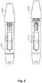
- Fig. 4shows in part a system 2 comprising a first pair of a first cartridge holder 410 and corresponding first pen cap 420, a second pair of a second cartridge holder 510 and corresponding second pen cap 520, and a third pair of a third cartridge holder 610 and corresponding third pen cap 620.
- the main portions of the drug delivery devicesare represented only by the cartridge holders, however, the remaining part of each main portion may have the same general configuration as the drug delivery device shown and described with reference to fig. 1 .
- the cartridge holders and the pen capshave the same general configuration comprising a number of common features which will be described with reference to the first pair.
- the cartridge holder 410comprises a central portion adapted to hold a drug cartridge and being provided with a number of windows or openings 401 allowing a drug-filled transparent cartridge to be inspected by a user, a proximal portion 402 adapted to engage a pen body, and a distal portion 403 comprising a mount in the form of a bayonet coupling for a needle assembly.
- the cartridge holder coding structurecomprises first, second and third axially oriented grooves 411, 412, 413 with a pair of axially oriented ribs 415, 416 arranged between the first and second respectively the second and third groove.
- the ribsare flush with the surrounding general surface of the cartridge holder.
- the distally facing free end surfaces 418, 419 of the ribs and the neighbouring cartridge holderare inclined towards the central second groove, thereby serving as a guide for the key structures on the cab, see below.
- the central groovealso serves as a window to allow inspection of the cartridge.
- the pen cap 420 in fig. 4is shown in a longitudinal cross-sectional view disclosing one of two pairs of 180 degrees opposed "key" coding structures arranged on the proximal inner surface of the pen cap, i.e. the shown key is adapted to engage the opposed hidden key hole structure on the cartridge holder 410.
- the coding structurecomprises first, second and third axially oriented ribs 421, 422, 423 with a pair of axially oriented grooves 415, 416 arranged between the first and second respectively the second and third rib.
- the groovesare flush with the surrounding general inner surface of the pen cap.
- the coding structuresmay be arranged proximally on the cartridge with the cap coding structures arranged in the vicinity of the cap opening.
- the specific spacing and width of the ribs 421, 422, 423corresponds to the spacing and width of the grooves 411, 412, 413 on the cartridge holder 410, this allowing the first pen cap 420 to be axially mounted on the first cartridge holder 410.
- Thisis illustrated in fig. 5 showing the first cartridge holder and the first pen cap in fitting engagement. As appears, to illustrate the engagement the distal wall portion of the cap has been cut away leaving only the rig structures.
- Fig. 5also shows how the specific spacing of ribs 621, 622, 623 and grooves 511, 512, 513 prevents the third cap 620 to axially engage the second cartridge holder.
- the three different cartridge holderscould be permanently attached to three pen main bodies and used to hold three drug cartridges containing three different drugs, the three pen caps being provided in three different colours corresponding to the different drugs.
- the coding system of the inventionwould prevent a wrong cap to be mounted on a given cartridge holder, thereby reducing the risk that a user would grab and use a wrong pen comprising the wrong drug.
- a systemcomprising two or more inhalation devices, each device comprising aerosol generating means, an outlet in the form of a mouthpiece and a protective cap adapted to be mounted on the mouthpiece, e.g. as known from US 7,278,425 .
- the corresponding key structuresmay be arranged on the mouthpiece respectively the cap.
Landscapes
- Health & Medical Sciences (AREA)
- Engineering & Computer Science (AREA)
- Life Sciences & Earth Sciences (AREA)
- Animal Behavior & Ethology (AREA)
- Anesthesiology (AREA)
- Biomedical Technology (AREA)
- Heart & Thoracic Surgery (AREA)
- Hematology (AREA)
- Veterinary Medicine (AREA)
- Vascular Medicine (AREA)
- General Health & Medical Sciences (AREA)
- Public Health (AREA)
- Environmental & Geological Engineering (AREA)
- Infusion, Injection, And Reservoir Apparatuses (AREA)
- Medical Preparation Storing Or Oral Administration Devices (AREA)
- Closures For Containers (AREA)
Description
- The present invention generally relates to medical delivery devices. In specific embodiments the invention relates to injection devices adapted for transcutaneous delivery of an amount of drug.
- In the disclosure of the present invention reference is mostly made to the treatment of diabetes by delivery of insulin-containing drugs, however, this is only an exemplary use of the present invention.
- Drug injection devices (typically for subcutaneous delivery) have greatly improved the lives of patients who must self-administer drugs and biological agents. Drug injection devices may take many forms, including simple disposable devices that are little more than an ampoule with an injection means or they may be highly sophisticated electronically controlled instruments with numerous functions. Regardless of their form, they have proven to be great aids in assisting patients to self-administer injectable drugs and biological agents. They also greatly assist care givers in administering injectable medicines to those incapable of performing self-injections.
- In particular pen-style injection devices have proven to provide an accurate, convenient, and often discrete, way to administer drugs and biological agents, such as insulin. Modern devices have become more sophisticated and often include diverse and robust functions, such as memories for remembering time and amount of last dose, as well as, in the case of insulin devices, blood glucose monitors. While pen-style injection devices are typically cylindrically shaped with a needle protruding from the most distal portion of one end of the device, some devices have other shapes with the needle no longer protruding from the most distal part of an end of the device, e.g. Innovo ® and InnoLet ® from Novo Nordisk A/S, Bagsvaerd, Denmark.
- Typically, injection devices use a pre-filled cartridge containing the medication of interest, e.g. 1.5 or 3.0 ml of insulin or growth hormone. The cartridge is typically in the form of a generally cylindrical transparent ampoule with a needle pierceable septum at one end and an opposed piston designed to be moved by the dosing mechanism of the injection device. The injection devices generally are of two types: "Durable" devices and "disposable" devices. A durable device is designed to allow a user to replace one cartridge with another cartridge, typically a new cartridge in place of an empty cartridge. In contrast, a disposable device is provided with an integrated cartridge which cannot be replaced by the user; when the cartridge is empty the entire device is discarded. Most injection devices are provided with a releasable pen cap covering the cartridge and the needle mount portion (see below), this allowing the user to inspect the content of the cartridge by removing the cap.
- Often injection devices are provided as a system or family of devices containing different types of drugs, e.g. as known from
WO 2004/069314 . This application discloses a system of substantially identical injection devices, each individual injection device comprising a housing accommodating an ampoule containing drug sufficient for a number of injections and a dose setting mechanism by which a predetermined dose size can be set, and wherein each of the plurality of injection devices has a different predetermined dose size. The difference in the predetermined dose sizes can in one embodiment be based on the drug in the devices having different strength. - People suffering from diabetes are often treated with multiple daily injections in a regimen comprising one or two daily injections of long acting insulin to cover the basal requirement supplemented by bolus injections of short or rapid acting insulin to cover requirements related to meals.
- A user will therefore often require two different injection devices, one containing the long acting insulin and another containing the short or rapid acting insulin. Often these injection devices have different colour indications to inform the user of the kind of insulin contained in the injection device. For example, the FlexPen ® system offered by Novo Nordisk comprises pens for long and short acting insulins as well as for mixed insulin, the bodies and caps being identical with colour markings on the main body to differentiate the two types of insulin. In the SoloStar ® system offered by Sanofi-Aventis the pens for long and short acting insulins have differently coloured bodies as well as caps. In addition these injection devices can be provided with tactile means such as a mechanical coding informing the user of the kind of insulin contained in the injection device.
DE U 201 10 689 discloses a pen-shaped injection device having a cap with a clip for holding the injection device e.g. in a pocket of a shirt. The injection device is contained in a cut-out in a box. The physical shape of the injection device is according to this reference designed such that the right injection device fits into the right box. This is according to the prior art done by having devices with different of length of the clip and boxes with a similar shaped cut-out.DE 201 10 690 discloses an injection device comprising a driver portion, a cartridge and a cartridge holder. The cartridge holder can be provided with a coded ring-shaped protecting member which allows only a specifically configured cartridge to be mounted in the cartridge holder. - Another technique for drug delivery is to use pulmonary delivery of an aerosolized pharmaceutical formulation so that the active drug within the dispersion can reach the more or less distal regions of the lung. This way of administration has been used extensively for e.g. local administration of drugs for treatment of respiratory deceases, e.g. asthma, but has also been proposed for the treatment of diabetes with insulin. A variety of aerosolization systems have been proposed to disperse pharmaceutical formulations. For example,
US 5,785,049 andUS 5,740,794 , describe exemplary powder dispersion devices which utilize a compressed gas to aerosolize a powder. Other types of aerosolization systems include so-called MDI's (which typically have a drug that is stored in a propellant), nebulizers (which aerosolize liquids using compressed gas, usually air), and the like. Another technique is the use of inspired gases to disperse the pharmaceutical formulation. In this way, the patient is able to provide the energy needed to aerosolize the formulation by the patient's own inhalation. Corresponding to the administration of two or more drugs using injection devices, it may also be necessary to use two or more inhalation devices. - Although the prior art discloses a number of solutions of how to differentiate similar or otherwise identical drug delivery devices containing different kinds of drugs, there is still a need for drug delivery devices which in a simple and effective manner provides a strong identification of the kind of drug contained in a specific device, this reducing the risk of a user inadvertently taking the incorrect kind of drug.
- Having regard to the above, it is an object of the present invention to provide a system of drug delivery devices which in a simple and cost-effective manner reduces the likelihood of a user taking the wrong kind of drug.
- In the disclosure of the present invention, embodiments and aspects will be described which will address one or more of the above objects or which will address objects apparent from the below disclosure as well as from the description of exemplary embodiments.
- Thus, in accordance with a first aspect a system is provided comprising at least first and second drug delivery devices. The first drug delivery device comprises a first main portion comprising a first reservoir holding a first type of drug, a first drug outlet, and first drug expelling means (e.g. mechanical means operated by the user of by electric power or a pressurized propellant) for expelling drug from the first reservoir through the first drug outlet, as well as a first cap releasably mountable to the first main portion to enclose the first drug outlet, the first cap comprising a first user-identifiable marking (e.g. visual or tactile) indicating the first type of drug. The second drug delivery device comprises a second main portion comprising a second reservoir holding a second type of drug, a second drug outlet, and second drug expelling means for expelling drug from the second reservoir through the second drug outlet, as well as a second cap releasably mountable to the second main portion to enclose the second mount, the second cap comprising a second user-identifiable marking indicating the second type of drug. The cap and main portion of each drug delivery device comprise a pair of corresponding key structures preventing the first cap from being mounted on the second main portion, and the second cap from being mounted on the first main portion. Indeed, this feature would be the case for any two completely different devices, thus the drug delivery devices in the system of the present invention are based on the same technology platform.
- "Technology platform" is meant to mean the basic structure upon which the injection devices in the system are based, e.g. the mechanism for setting and expelling a dose of fluid drug from a drug-filled cartridge. In order to be based on the same technology platform, the injection devices of the system must work by the same mechanical principles i.e. the individual constructional components of each injection device must be the same and interact in the same way. Technology platform products share underlying structures or basic architectures that are common across a group of products or that will be the basis of a series of products commercialized over a number of years. Several products may be derived from a common technology platform. Members of a product family normally have many common parts and assemblies. Thus, two drug delivery devices sharing the same technology platform may in accordance with the present invention have e.g. at least 50%, 75% or 90% interchangeable parts (excluding non-structural parts as e.g. labels). To be interchangeable the parts may be morphologically identical or they may be fully identical.
- By providing a system in which a given device cap can only be mounted on a corresponding device main portion the cap can be used to safely identify the drug content of a given drug delivery device without the risk of a user mounting a given cap on a non-corresponding device main portion with the possible risk of taking the wrong medication, e.g. mounting a cap indicating short acting insulin on a main device portion containing long acting insulin. The different caps of the system may vary by e.g. colour and/or physical configuration.
- As appears, the above-described coding feature provides a drug delivery system which is much safer in use than previous systems on the markets using e.g. colour marked caps, such caps being identical apart from the colour and thus allowing non-corresponding caps and main portions to be attached to each other with the resulting possible risk of taking the wrong medication.
- The delivery system may comprise at least one further drug delivery device, each further device having a main portion and a cap comprising a pair of corresponding key structures, wherein the key structure of any given cap prevents the given cap to be mounted on a main portion of another drug delivery device of the system.
- In exemplary embodiments the corresponding key structures are mechanical, e.g. "key hole" and "key" structures allowing only corresponding cap and main portions to be assembled. The key structure of each cap may be arranged interiorly in the cap, whereas each main portion of the system may comprise a reservoir holder enclosing at least a portion of a reservoir, the reservoir holder comprising the key structure of the main portion.
- Alternatively the corresponding key structures may be electronic or electric, e.g. in case the cap and/or the main portion comprise electronic means, placing a non-corresponding cap on a given main portion would result in the cap and/or main portion producing an alarm, e.g. a visual, tactile or sound signal.
- In exemplary embodiments the drug delivery devices are drug injection devices adapted to expel a liquid drug formulation from a reservoir, e.g. a cartridge comprising a displaceable piston. The means for displacing the piston and thereby expel drug may be in the form of a user settable and user actuated mechanism, e.g. as disclosed in
US 6,004,297 orUS 2009/ 054839 . - In an exemplary embodiment each main portion comprises a mount for mounting a needle assembly in fluid communication with the reservoir, the corresponding cap being adapted to enclose the mount when mounted on the main portion. The system may correspondingly comprise one or more needle assemblies each comprising a hub adapted to be mounted on any of the mounts of the system, and a hollow needle mounted in the hub and comprising a distal pointed end and a proximal end, the proximal end being adapted to be arranged in fluid communication with a reservoir when the hub is mounted on a mount. When mounted on a corresponding main portion the caps of the system may be adapted to enclose a needle assembly mounted on the mount.
- In a further exemplary embodiment each main portion comprises a mouthpiece, the corresponding cap being adapted to enclose the mouthpiece when mounted on the main portion.
- To further improve handling and convenience the cap may be provided with one or more inspection openings or windows allowing a user to inspect at least a portion of a mounted needle assembly. In this way a user does not have to remove the cap to check if a needle assembly is mounted or to check the reservoir.
- Correspondingly, the main portion may be provided with a user-inspectable portion adapted to be covered by the cap in a mounted position, the cap being provided with one or more inspection openings or windows allowing a user to inspect at least a portion of the user-inspectable portion when the cap is mounted on the main portion.
- For example, the user-inspectable portion may comprise a transparent reservoir portion allowing a user to inspect drug contained in the reservoir or the position of a piston located in the reservoir. For easier inspection of the transparent reservoir the cap may be provided with a second set of inspection openings or windows arranged generally opposite the first set, this allowing light to travel through the reservoir.
- The cap may be generally non-transparent and be provided with one or more transparent windows, the transparent windows comprising means for reducing transmission of light detrimental to drug contained in the reservoir, e.g. a UV filter. The cap may optionally be provided with the additional features described in co-pending applications
PCT/EP2010/058322 - In the above described embodiments the main portion of the drug delivery device comprises a reservoir, however, in alternative versions the different embodiments may be adapted to receive a replaceable reservoir, e.g. a cartridge or canister to be used in combination with a durable type delivery device.
- As used herein, the term "drug" is meant to encompass any drug-containing formulation capable of being administered to a patient in a controlled manner, e.g. passed through a delivery means such as a cannula or hollow needle, such as a liquid, solution, gel or fine suspension, or passed through a nozzle or mouthpiece as an aerosol or powder. Representative drugs include pharmaceuticals such as peptides (e.g. insulins, insulin containing drugs, GLP-1 containing drugs as well as derivates thereof), proteins, and hormones, biologically derived or active agents, hormonal and gene based agents, nutritional formulas and other substances in either solid (dispensed), powder or liquid form. In the description of the exemplary embodiments reference will be made to the use of insulin containing drugs or drugs having insulin-like effects. Correspondingly, the term "subcutaneous" infusion is meant to encompass any method of transcutaneous delivery to a subject.
- In the following the invention will be further described with reference to the drawings, wherein
fig. 1 shows a drug delivery pen and a needle assembly,fig. 2 shows two pairs of pen caps and cartridge holders corresponding to a first embodiment of the invention,fig. 3 shows match and mismatch of pen caps and cartridge holders of the first embodiment,fig. 4 shows three pairs of pen caps and cartridge holders corresponding to a second embodiment of the invention, andfig. 5 shows match and mismatch of pen caps and cartridge holders of the second embodiment.- In the figures like structures are mainly identified by like reference numerals.
- When in the following terms such as "upper" and "lower", "right" and "left", "horizontal" and "vertical" or similar relative expressions are used, these only refer to the appended figures and not to an actual situation of use. The shown figures are schematic representations for which reason the configuration of the different structures as well as there relative dimensions are intended to serve illustrative purposes only.
- Referring to
fig. 1 a pen-formed drug delivery device 1 will be described. The device corresponds to the general type of device to which the present invention relates but does not incorporate the present invention. The pen comprises a cap portion (or "pen cap") 100 and a main (or body)portion 3 having aproximal part 4 in which a drug expelling mechanism is arranged, and adistal reservoir part 5 in which a drug-filledtransparent cartridge 6 with a distal needle-penetratable septum is arranged and hold in place by acartridge holder 7 mounted to the proximal part, the cartridge holder having openings allowing a portion of the cartridge to be inspected. The cartridge is provided with apiston 8 driven by a piston rod 9 forming part of the expelling mechanism. Aproximal-most button 10 serves to manually set and expel a desired dose of drug. This type of a pen-formed drug delivery device is well known, see e.g.WO 99/38554 cylindrical sleeve 101 with a proximal closed end and adistal opening 102, apocket clip 103 and aninspection opening 104. The proximal end is provided with two opposed generally planar gripping surfaces 110. Special features like e.g. the inspection opening and the gripping surfaces are not relevant for the present invention. Fig. 1 further shows a needle assembly comprising ahollow infusion needle 21 mounted a cup-formedhub 22 with an inner coupling means in the form of a thread adapted to connect to the external thread 11 of the pen device. The needle comprises a distal pointed portion protruding from the hub as well as a proximal pointed portion adapted to penetrate the cartridge septum when thehub 22 is mounted on the thread 11. In an alternative embodiment a bayonet coupling may be used instead of the threaded connection, e.g. the cup may be provided with a plurality of inwardly projecting protrusions adapted to engage corresponding grooves formed distally on the pen device as disclosed inUS 2008/0015519 and shown infig. 4 . The needle assembly further comprises aneedle cap 23 with askirt portion 24 adapted to releasably engage the hub to thereby protect the distal end of the needle. The needle is normally provided sterile in a container (not shown) having an opening sealed by a peelable membrane, the container being in releasable, e.g. frictional, engagement with the needle hub. The pen-formed drug delivery device 1 and the needle assembly together form a system.- Turning to
figs. 2 and 3 a first embodiment of the invention will be illustrated.Fig. 2 shows a pair of afirst cartridge holder 210 and corresponding first pen cap 220 (in fact, two identical first caps are shown), the pen having a number of axially arranged ribs at the proximal end and the cap having a number of corresponding projections at its proximal end adapted to fit between the ribs. More specifically, the first cartridge holder is provided with three ribs in the form of a centralwider rib 212 and two more narrow outer ribs on each side, thereby forming twocartridge slots portion 221 with two opposed axially arrangededges projections central cap slot 222 between the two projections as well as second andthird cap slots - In accordance with the invention the specific combination of
ribs cap slots fig. 3 . As also appears, the inclined surfaces of the on the cap projections help guide thecentral rib 212 into the gap between the projections. Fig. 2 also shows asecond cartridge holder 310 provided with a similar set ofribs fig. 3 . Indeed, a second cap (not shown) with a key corresponding to the second cartridge holder will be provided in a system in accordance with the invention, such a second cap having a combination of slots allowing it to be mounted on thesecond cap 310 but not on thefirst cap 210. Indeed, a system in accordance with the invention may comprise three or more matching pairs of a cartridge holder and pen cap, the spacing and width of the ribs and corresponding slots being unique for each such pair.- Turning to
figs. 4 and5 a second embodiment of the invention will be described.Fig. 4 shows in part asystem 2 comprising a first pair of afirst cartridge holder 410 and correspondingfirst pen cap 420, a second pair of asecond cartridge holder 510 and correspondingsecond pen cap 520, and a third pair of athird cartridge holder 610 and correspondingthird pen cap 620. The main portions of the drug delivery devices are represented only by the cartridge holders, however, the remaining part of each main portion may have the same general configuration as the drug delivery device shown and described with reference tofig. 1 . The cartridge holders and the pen caps have the same general configuration comprising a number of common features which will be described with reference to the first pair. - The
cartridge holder 410 comprises a central portion adapted to hold a drug cartridge and being provided with a number of windows oropenings 401 allowing a drug-filled transparent cartridge to be inspected by a user, aproximal portion 402 adapted to engage a pen body, and adistal portion 403 comprising a mount in the form of a bayonet coupling for a needle assembly. - Distally on the central portion two sets of 180 degrees opposed coding structures are arranged, each set providing a "key hole" into which a corresponding "key" of a pen cap will fit. More specifically, the cartridge holder coding structure comprises first, second and third axially oriented
grooves ribs - The
pen cap 420 infig. 4 is shown in a longitudinal cross-sectional view disclosing one of two pairs of 180 degrees opposed "key" coding structures arranged on the proximal inner surface of the pen cap, i.e. the shown key is adapted to engage the opposed hidden key hole structure on thecartridge holder 410. The coding structure comprises first, second and third axially orientedribs grooves - The specific spacing and width of the
ribs grooves cartridge holder 410, this allowing thefirst pen cap 420 to be axially mounted on thefirst cartridge holder 410. This is illustrated infig. 5 showing the first cartridge holder and the first pen cap in fitting engagement. As appears, to illustrate the engagement the distal wall portion of the cap has been cut away leaving only the rig structures. Fig. 5 also shows how the specific spacing ofribs grooves third cap 620 to axially engage the second cartridge holder.- In a specific implementation of the second embodiment the three different cartridge holders could be permanently attached to three pen main bodies and used to hold three drug cartridges containing three different drugs, the three pen caps being provided in three different colours corresponding to the different drugs. As appears, the coding system of the invention would prevent a wrong cap to be mounted on a given cartridge holder, thereby reducing the risk that a user would grab and use a wrong pen comprising the wrong drug.
- In an alternative embodiment a system comprising two or more inhalation devices is provided, each device comprising aerosol generating means, an outlet in the form of a mouthpiece and a protective cap adapted to be mounted on the mouthpiece, e.g. as known from
US 7,278,425 . In such a system the corresponding key structures may be arranged on the mouthpiece respectively the cap. - In the above description of the preferred embodiments, the different structures and means providing the described functionality for the different components have been described to a degree to which the concept of the present invention will be apparent to the skilled reader. The detailed construction and specification for the different components are considered the object of a normal design procedure performed by the skilled person along the lines set out in the present specification, as set out in the claims.
Claims (10)
- A drug delivery system comprising a first drug delivery device comprising:(a1) a first main portion (410) comprising:- a first reservoir holding a first type of drug,- a first drug outlet, and- first drug expelling means for expelling drug from the first reservoir through the first drug outlet,characterized in thatthe first drug delivery device further comprises:(b1) a first cap (420) releasably mountable to the first main portion to enclose the first drug outlet, the first cap comprising a first user-identifiable marking indicating the first type of drug,the system further comprising a second drug delivery device comprising:(a2) a second main portion (510) comprising:- a second reservoir holding a second type of drug,- a second drug outlet, and- second drug expelling means for expelling drug from the second reservoir through the second drug outlet,(b2) a second cap (520) releasably mountable to the second main portion to enclose the second drug outlet, the second cap comprising a second user-identifiable marking indicating the second type of drug,wherein the cap and main portion of each drug delivery device comprise a pair of corresponding key structures (421, 422, 423, 411, 412, 413) preventing the first cap from being mounted on the second main portion, and the second cap from being mounted on the first main portion, andwherein the drug delivery devices in the system are based on the same technology platform by having at least 50% interchangeable parts.
- A drug delivery system as in claim 1, wherein each main portion comprises a mount (11, 403) for mounting a needle assembly (21, 22) in fluid communication with the reservoir, the corresponding cap being adapted to enclose the mount when mounted on the main portion.
- A drug delivery system as in claim 2, further comprising at least one needle assembly comprising:- a hub (22) adapted to be mounted on any of the mounts of the system, and- a hollow needle (21) mounted in the hub and comprising a distal pointed end and a proximal end, the proximal end being adapted to be arranged in fluid communication with a reservoir when the hub is mounted on a mount.
- A drug delivery system as in claim 3, wherein each cap of the system when mounted on a corresponding main portion are adapted to enclose a needle assembly mounted on the mount.
- A drug delivery system as in claim 1, wherein each main portion comprises a mouthpiece, the corresponding cap being adapted to enclose the mouthpiece when mounted on the main portion.
- A drug delivery system as in any of the proceeding claims, comprising at least one further drug delivery device (610), each having a main portion and a cap (620) comprising a pair of corresponding key structures, wherein the key structure of any given cap prevents the given cap from being mounted on a main portion of another drug delivery device of the system.
- A drug delivery system as in any of the proceeding claims, wherein the corresponding key structures (421, 422, 423, 411, 412, 413) are mechanical.
- A drug delivery system as in claim 7, wherein the key structure of each cap is arranged interiorly in the cap.
- A drug delivery system as in any of the proceeding claims, wherein each main portion of the system comprises a reservoir holder enclosing at least a portion of a reservoir, the reservoir holder comprising the key structure of the main portion.
- A drug delivery system as in any of claims 1-6, wherein the corresponding key structures are electric or electronic.
Priority Applications (1)
| Application Number | Priority Date | Filing Date | Title |
|---|---|---|---|
| EP10754720.0AEP2480266B1 (en) | 2009-09-21 | 2010-09-09 | Drug delivery system and device with cap function |
Applications Claiming Priority (5)
| Application Number | Priority Date | Filing Date | Title |
|---|---|---|---|
| EP09170841 | 2009-09-21 | ||
| EP09174420 | 2009-10-29 | ||
| US25804309P | 2009-11-04 | 2009-11-04 | |
| PCT/EP2010/063246WO2011032883A1 (en) | 2009-09-21 | 2010-09-09 | Drug delivery system and device with cap function |
| EP10754720.0AEP2480266B1 (en) | 2009-09-21 | 2010-09-09 | Drug delivery system and device with cap function |
Publications (2)
| Publication Number | Publication Date |
|---|---|
| EP2480266A1 EP2480266A1 (en) | 2012-08-01 |
| EP2480266B1true EP2480266B1 (en) | 2018-05-30 |
Family
ID=42813175
Family Applications (1)
| Application Number | Title | Priority Date | Filing Date |
|---|---|---|---|
| EP10754720.0ANot-in-forceEP2480266B1 (en) | 2009-09-21 | 2010-09-09 | Drug delivery system and device with cap function |
Country Status (9)
| Country | Link |
|---|---|
| US (1) | US10166338B2 (en) |
| EP (1) | EP2480266B1 (en) |
| JP (1) | JP5718338B2 (en) |
| CN (1) | CN102481405B (en) |
| AU (1) | AU2010294628B2 (en) |
| BR (1) | BR112012006268A2 (en) |
| CA (1) | CA2773626A1 (en) |
| RU (1) | RU2549310C2 (en) |
| WO (1) | WO2011032883A1 (en) |
Families Citing this family (40)
| Publication number | Priority date | Publication date | Assignee | Title |
|---|---|---|---|---|
| EP4233945B1 (en) | 2009-12-04 | 2025-06-04 | Becton, Dickinson and Company | Pen needle removal device for a drug delivery device |
| CA2795856A1 (en)* | 2010-04-09 | 2011-10-13 | Sanofi-Aventis Deutschland Gmbh | Coded cap for use with a drug delivery device |
| FI3060276T3 (en) | 2013-10-24 | 2023-06-07 | Infusion system for preventing mischanneling of multiple medicaments | |
| NZ724010A (en)* | 2014-02-26 | 2022-05-27 | Allergan Inc | Intraocular implant delivery apparatus and methods of use thereof |
| CN106573115B (en)* | 2014-08-25 | 2019-12-24 | 诺和诺德股份有限公司 | Attachment with snap-fit feature |
| WO2016198540A2 (en)* | 2015-06-11 | 2016-12-15 | Novo Nordisk A/S | Drug delivery device with extended protective cap |
| EP3319662B1 (en) | 2015-07-08 | 2023-09-13 | Trustees of Boston University | Infusion system and components thereof |
| EP3407940A4 (en) | 2016-01-29 | 2019-09-04 | Companion Medical, Inc. | AUTOMATIC DRUG DELIVERY MONITORING |
| USD819198S1 (en) | 2016-04-28 | 2018-05-29 | Amgen Inc. | Autoinjector with removable cap |
| WO2018002044A1 (en) | 2016-06-29 | 2018-01-04 | Novo Nordisk A/S | Drug delivery device with drug differentiation feature |
| EP3332823A1 (en)* | 2016-12-07 | 2018-06-13 | Sanofi-Aventis Deutschland GmbH | A cap for an injection device |
| BR112019013985A2 (en)* | 2017-01-06 | 2020-03-03 | Trustees Of Boston University | INFUSION SYSTEM AND COMPONENTS OF THE SAME |
| US11197964B2 (en) | 2017-12-12 | 2021-12-14 | Bigfoot Biomedical, Inc. | Pen cap for medication injection pen having temperature sensor |
| US10987464B2 (en) | 2017-12-12 | 2021-04-27 | Bigfoot Biomedical, Inc. | Pen cap for insulin injection pens and associated methods and systems |
| US11464459B2 (en) | 2017-12-12 | 2022-10-11 | Bigfoot Biomedical, Inc. | User interface for diabetes management systems including flash glucose monitor |
| IL275301B2 (en) | 2017-12-12 | 2024-01-01 | Bigfoot Biomedical Inc | Therapy assist information and/or tracking device and related methods and systems |
| US11077243B2 (en) | 2017-12-12 | 2021-08-03 | Bigfoot Biomedical, Inc. | Devices, systems, and methods for estimating active medication from injections |
| US11116899B2 (en) | 2017-12-12 | 2021-09-14 | Bigfoot Biomedical, Inc. | User interface for diabetes management systems and devices |
| US11083852B2 (en) | 2017-12-12 | 2021-08-10 | Bigfoot Biomedical, Inc. | Insulin injection assistance systems, methods, and devices |
| EP3597239A1 (en) | 2018-07-18 | 2020-01-22 | Sanofi | System for a drug delivery device |
| EP3597238A1 (en) | 2018-07-18 | 2020-01-22 | Sanofi | Cartridge assembly and method for assembling the same |
| EP3597233A1 (en) | 2018-07-18 | 2020-01-22 | Sanofi | Drug delivery devices |
| EP3597236A1 (en) | 2018-07-18 | 2020-01-22 | Sanofi | Cartridge assembly for a drug delivery device and method for assembling the same |
| EP3597237A1 (en) | 2018-07-18 | 2020-01-22 | Sanofi | Cartridge assembly for a drug delivery device and drug delivery device |
| EP3597240A1 (en) | 2018-07-18 | 2020-01-22 | Sanofi | Cartridge unit for a drug delivery device |
| US12205699B1 (en) | 2018-10-30 | 2025-01-21 | Bigfoot Biomedical, Inc. | Method of pairing therapy devices using shared secrets, and related systems, methods and devices |
| US11948671B2 (en) | 2019-04-11 | 2024-04-02 | Medtronic Minimed, Inc. | Intelligent accessories for medicine dispensing device |
| CA3146964A1 (en) | 2019-07-16 | 2021-01-21 | Beta Bionics, Inc. | Ambulatory device and components thereof |
| USD1010811S1 (en) | 2019-09-30 | 2024-01-09 | Amgen Inc. | Handheld drug delivery device |
| USD1030041S1 (en) | 2020-01-14 | 2024-06-04 | Amgen Inc. | Handheld drug delivery device |
| USD1030040S1 (en) | 2020-01-14 | 2024-06-04 | Amgen Inc. | Handheld drug delivery device |
| US11278661B2 (en) | 2020-03-10 | 2022-03-22 | Beta Bionics, Inc. | Infusion system and components thereof |
| USD1031975S1 (en) | 2020-03-10 | 2024-06-18 | Beta Bionics, Inc. | Medicament infusion pump device |
| USD973866S1 (en) | 2020-11-05 | 2022-12-27 | Amgen Inc. | Handheld drug delivery device |
| USD974547S1 (en) | 2020-11-05 | 2023-01-03 | Amgen Inc. | Handheld drug delivery device |
| USD962423S1 (en) | 2020-11-05 | 2022-08-30 | Amgen Inc. | Handheld drug delivery device |
| USD985118S1 (en) | 2021-03-10 | 2023-05-02 | Amgen Inc. | Handheld drug delivery device |
| USD985116S1 (en) | 2021-03-10 | 2023-05-02 | Amgen Inc. | Handheld drug delivery device |
| USD985117S1 (en) | 2021-03-10 | 2023-05-02 | Amgen Inc. | Handheld drug delivery device |
| USD985119S1 (en) | 2021-03-30 | 2023-05-02 | Amgen Inc. | Handheld drug delivery device |
Family Cites Families (30)
| Publication number | Priority date | Publication date | Assignee | Title |
|---|---|---|---|---|
| US4883049A (en)* | 1985-06-13 | 1989-11-28 | Southmedic Incorporated | Apparatus for use in refilling an anesthetic vaporizer |
| JPH01179861A (en)* | 1988-01-08 | 1989-07-17 | Rinnai Corp | Hot air space heater |
| DK166948B1 (en)* | 1988-02-10 | 1993-08-09 | Dcp Af 1988 As | DOSING UNIT FOR DOSING A NUMBER OF MEASURED QUANTITIES OF A FLUID, SUCH AS INSULIN, FROM A GLASS STUBLE |
| JPH0426337Y2 (en)* | 1988-06-09 | 1992-06-24 | ||
| US5213483A (en)* | 1991-06-19 | 1993-05-25 | Strato Medical Corporation | Peristaltic infusion pump with removable cassette and mechanically keyed tube set |
| AU1812392A (en)* | 1991-07-12 | 1993-01-14 | Minnesota Mining And Manufacturing Company | Bottle keying system |
| DK175491D0 (en)* | 1991-10-18 | 1991-10-18 | Novo Nordisk As | APPARATUS |
| US5569026A (en)* | 1992-06-18 | 1996-10-29 | Storz Endoskop Gmbh | Tube pump in which tube can be inserted only in one direction |
| US5785049A (en) | 1994-09-21 | 1998-07-28 | Inhale Therapeutic Systems | Method and apparatus for dispersion of dry powder medicaments |
| US5334162A (en)* | 1993-03-15 | 1994-08-02 | Eli Lilly And Company | Cartridge assembly for a lyophilized compound forming a disposable portion of an injector pen and method for same |
| US5725508A (en)* | 1994-06-22 | 1998-03-10 | Becton Dickinson And Company | Quick connect medication delivery pen |
| US5530531A (en)* | 1995-03-15 | 1996-06-25 | Hewlett-Packard Company | Multiple cartridge keying apparatus |
| IT1281248B1 (en) | 1995-11-16 | 1998-02-17 | Pier Luigi Delvigo | MEDICAL SAFETY DEVICE FOR TRANSFUSIONS. |
| US5954700A (en)* | 1998-01-13 | 1999-09-21 | Minimed Inc. | Medication cartridge for an electronic pen-type injector, or the like, and method of making the same |
| CZ297361B6 (en) | 1998-01-30 | 2006-11-15 | Novo Nordisk A/S | Injection syringe |
| US6766799B2 (en) | 2001-04-16 | 2004-07-27 | Advanced Inhalation Research, Inc. | Inhalation device |
| DE20110689U1 (en)* | 2001-06-27 | 2002-01-03 | Spyra, Heinrich, 91056 Erlangen | Storage box for injection aids with confusion protection and with other identifying features |
| DE20110690U1 (en)* | 2001-06-27 | 2001-09-13 | Spyra, Heinrich, 91056 Erlangen | Protection against confusion to prevent an injection aid from being fitted with the wrong medication ampoule |
| ATE333260T1 (en)* | 2001-08-27 | 2006-08-15 | Novo Nordisk As | A CARTRIDGE AND A MEDICAL DELIVERY SYSTEM THAT ACCOMMODATE SUCH A CARTRIDGE |
| SE0201142D0 (en)* | 2002-04-16 | 2002-04-16 | Pharmacia Ab | A system and method for modification of a device and a device suitable for modification |
| US7654986B2 (en) | 2002-07-03 | 2010-02-02 | Novo Nordisk A/S | Needle mounting system and a method for mounting a needle assembly |
| JP2004166847A (en)* | 2002-11-18 | 2004-06-17 | Otsuka Pharmaceut Factory Inc | Infusion mixing device, mixing tube, chemical solution container, mixed solution container, infusion formulation system, and infusion formulation method |
| DE602004031927D1 (en) | 2003-02-04 | 2011-05-05 | Novo Nordisk As | INJECTION DEVICE WITH ROTATABLE DOSE ADJUSTMENT DEVICE |
| DE102004009434A1 (en) | 2004-02-24 | 2005-12-15 | Boehringer Ingelheim International Gmbh | atomizer |
| KR101278123B1 (en) | 2004-10-21 | 2013-06-24 | 노보 노르디스크 에이/에스 | Injection device with torsion spring and rotatable display |
| WO2007060156A1 (en) | 2005-11-22 | 2007-05-31 | Novo Nordisk A/S | System of different shaped injection devices |
| EP1979026A2 (en)* | 2006-01-06 | 2008-10-15 | Novo Nordisk A/S | A medication delivery device applying a collapsible reservoir |
| EP2083888A1 (en)* | 2006-11-17 | 2009-08-05 | Novo Nordisk A/S | A medical delivery system comprising a coding mechanism between dosing assembly and medicament container |
| CA2639320C (en)* | 2007-09-07 | 2016-10-25 | Becton, Dickinson And Company | Pen-needle assembly for preventing under-torquing and over-torquing of pen-needle |
| DE102008016987A1 (en)* | 2008-04-03 | 2009-10-08 | Rolf Hessenbruch | Insulin syringe i.e. injection pen, for injection of insulin in fatty tissue of diabetic, has closing cap fitted on mechanical part after utilization of syringe such that marking arrows mark and store time of last injection of insulin |
- 2010
- 2010-09-09EPEP10754720.0Apatent/EP2480266B1/ennot_activeNot-in-force
- 2010-09-09RURU2012113410/14Apatent/RU2549310C2/ennot_activeIP Right Cessation
- 2010-09-09WOPCT/EP2010/063246patent/WO2011032883A1/enactiveApplication Filing
- 2010-09-09CNCN201080042048.9Apatent/CN102481405B/ennot_activeExpired - Fee Related
- 2010-09-09BRBR112012006268Apatent/BR112012006268A2/ennot_activeIP Right Cessation
- 2010-09-09USUS13/496,671patent/US10166338B2/ennot_activeExpired - Fee Related
- 2010-09-09CACA2773626Apatent/CA2773626A1/ennot_activeWithdrawn
- 2010-09-09AUAU2010294628Apatent/AU2010294628B2/ennot_activeCeased
- 2010-09-09JPJP2012529217Apatent/JP5718338B2/ennot_activeExpired - Fee Related
Non-Patent Citations (1)
| Title |
|---|
| None* |
Also Published As
| Publication number | Publication date |
|---|---|
| AU2010294628B2 (en) | 2014-09-11 |
| WO2011032883A1 (en) | 2011-03-24 |
| BR112012006268A2 (en) | 2017-05-23 |
| AU2010294628A1 (en) | 2012-03-15 |
| RU2549310C2 (en) | 2015-04-27 |
| CA2773626A1 (en) | 2011-03-24 |
| CN102481405A (en) | 2012-05-30 |
| JP5718338B2 (en) | 2015-05-13 |
| RU2012113410A (en) | 2013-10-27 |
| CN102481405B (en) | 2014-06-18 |
| US20120232474A1 (en) | 2012-09-13 |
| EP2480266A1 (en) | 2012-08-01 |
| JP2013505036A (en) | 2013-02-14 |
| US10166338B2 (en) | 2019-01-01 |
Similar Documents
| Publication | Publication Date | Title |
|---|---|---|
| EP2480266B1 (en) | Drug delivery system and device with cap function | |
| EP2440270B1 (en) | Drug delivery device with cap functions for needle assembly | |
| ES2655593T3 (en) | Coded element for connecting drug reservoir with articulated flange | |
| EP2555814B1 (en) | Coded drug reservoir connection element with bendable locking elements | |
| JP5784702B2 (en) | Coded keying insert for drug cartridge | |
| WO2010142812A1 (en) | Drug delivery device with cap functions for inspection | |
| JP2013533076A (en) | Coding system and drug delivery system for drug delivery device | |
| TR201809157T4 (en) | Coded drug reservoir connector with hinge. | |
| JP2013523294A (en) | Method and system for identifying drug delivery devices | |
| US9636462B2 (en) | Drug delivery device with shield operated needle actuator | |
| JP5986099B2 (en) | Tamper evident indicator for drug reservoir | |
| CN103249444A (en) | Non-detachable reservoir holder for a drug delivery device | |
| WO2016198540A2 (en) | Drug delivery device with extended protective cap | |
| WO2018002044A1 (en) | Drug delivery device with drug differentiation feature | |
| US20210178076A1 (en) | Drug delivery system with drug differentiation feature | |
| WO2014072499A1 (en) | Drug delivery device with integrated shield | |
| HK1182035A (en) | Coded drug reservoir connection element with bendable locking elements | |
| HK1182035B (en) | Coded drug reservoir connection element with bendable locking elements |
Legal Events
| Date | Code | Title | Description |
|---|---|---|---|
| PUAI | Public reference made under article 153(3) epc to a published international application that has entered the european phase | Free format text:ORIGINAL CODE: 0009012 | |
| 17P | Request for examination filed | Effective date:20120423 | |
| AK | Designated contracting states | Kind code of ref document:A1 Designated state(s):AL AT BE BG CH CY CZ DE DK EE ES FI FR GB GR HR HU IE IS IT LI LT LU LV MC MK MT NL NO PL PT RO SE SI SK SM TR | |
| DAX | Request for extension of the european patent (deleted) | ||
| 17Q | First examination report despatched | Effective date:20160502 | |
| GRAP | Despatch of communication of intention to grant a patent | Free format text:ORIGINAL CODE: EPIDOSNIGR1 | |
| INTG | Intention to grant announced | Effective date:20180108 | |
| GRAS | Grant fee paid | Free format text:ORIGINAL CODE: EPIDOSNIGR3 | |
| GRAA | (expected) grant | Free format text:ORIGINAL CODE: 0009210 | |
| AK | Designated contracting states | Kind code of ref document:B1 Designated state(s):AL AT BE BG CH CY CZ DE DK EE ES FI FR GB GR HR HU IE IS IT LI LT LU LV MC MK MT NL NO PL PT RO SE SI SK SM TR | |
| REG | Reference to a national code | Ref country code:GB Ref legal event code:FG4D | |
| REG | Reference to a national code | Ref country code:CH Ref legal event code:EP | |
| REG | Reference to a national code | Ref country code:AT Ref legal event code:REF Ref document number:1002952 Country of ref document:AT Kind code of ref document:T Effective date:20180615 | |
| REG | Reference to a national code | Ref country code:IE Ref legal event code:FG4D | |
| REG | Reference to a national code | Ref country code:DE Ref legal event code:R096 Ref document number:602010050952 Country of ref document:DE | |
| REG | Reference to a national code | Ref country code:FR Ref legal event code:PLFP Year of fee payment:9 | |
| REG | Reference to a national code | Ref country code:NL Ref legal event code:MP Effective date:20180530 | |
| REG | Reference to a national code | Ref country code:LT Ref legal event code:MG4D | |
| PG25 | Lapsed in a contracting state [announced via postgrant information from national office to epo] | Ref country code:FI Free format text:LAPSE BECAUSE OF FAILURE TO SUBMIT A TRANSLATION OF THE DESCRIPTION OR TO PAY THE FEE WITHIN THE PRESCRIBED TIME-LIMIT Effective date:20180530 Ref country code:NO Free format text:LAPSE BECAUSE OF FAILURE TO SUBMIT A TRANSLATION OF THE DESCRIPTION OR TO PAY THE FEE WITHIN THE PRESCRIBED TIME-LIMIT Effective date:20180830 Ref country code:CY Free format text:LAPSE BECAUSE OF FAILURE TO SUBMIT A TRANSLATION OF THE DESCRIPTION OR TO PAY THE FEE WITHIN THE PRESCRIBED TIME-LIMIT Effective date:20180530 Ref country code:BG Free format text:LAPSE BECAUSE OF FAILURE TO SUBMIT A TRANSLATION OF THE DESCRIPTION OR TO PAY THE FEE WITHIN THE PRESCRIBED TIME-LIMIT Effective date:20180830 Ref country code:SE Free format text:LAPSE BECAUSE OF FAILURE TO SUBMIT A TRANSLATION OF THE DESCRIPTION OR TO PAY THE FEE WITHIN THE PRESCRIBED TIME-LIMIT Effective date:20180530 Ref country code:ES Free format text:LAPSE BECAUSE OF FAILURE TO SUBMIT A TRANSLATION OF THE DESCRIPTION OR TO PAY THE FEE WITHIN THE PRESCRIBED TIME-LIMIT Effective date:20180530 Ref country code:LT Free format text:LAPSE BECAUSE OF FAILURE TO SUBMIT A TRANSLATION OF THE DESCRIPTION OR TO PAY THE FEE WITHIN THE PRESCRIBED TIME-LIMIT Effective date:20180530 | |
| PGFP | Annual fee paid to national office [announced via postgrant information from national office to epo] | Ref country code:DE Payment date:20180821 Year of fee payment:9 Ref country code:FR Payment date:20180822 Year of fee payment:9 | |
| PG25 | Lapsed in a contracting state [announced via postgrant information from national office to epo] | Ref country code:LV Free format text:LAPSE BECAUSE OF FAILURE TO SUBMIT A TRANSLATION OF THE DESCRIPTION OR TO PAY THE FEE WITHIN THE PRESCRIBED TIME-LIMIT Effective date:20180530 Ref country code:GR Free format text:LAPSE BECAUSE OF FAILURE TO SUBMIT A TRANSLATION OF THE DESCRIPTION OR TO PAY THE FEE WITHIN THE PRESCRIBED TIME-LIMIT Effective date:20180831 Ref country code:HR Free format text:LAPSE BECAUSE OF FAILURE TO SUBMIT A TRANSLATION OF THE DESCRIPTION OR TO PAY THE FEE WITHIN THE PRESCRIBED TIME-LIMIT Effective date:20180530 | |
| PGFP | Annual fee paid to national office [announced via postgrant information from national office to epo] | Ref country code:CH Payment date:20180828 Year of fee payment:9 Ref country code:GB Payment date:20180823 Year of fee payment:9 | |
| REG | Reference to a national code | Ref country code:AT Ref legal event code:MK05 Ref document number:1002952 Country of ref document:AT Kind code of ref document:T Effective date:20180530 | |
| PG25 | Lapsed in a contracting state [announced via postgrant information from national office to epo] | Ref country code:NL Free format text:LAPSE BECAUSE OF FAILURE TO SUBMIT A TRANSLATION OF THE DESCRIPTION OR TO PAY THE FEE WITHIN THE PRESCRIBED TIME-LIMIT Effective date:20180530 | |
| PG25 | Lapsed in a contracting state [announced via postgrant information from national office to epo] | Ref country code:PL Free format text:LAPSE BECAUSE OF FAILURE TO SUBMIT A TRANSLATION OF THE DESCRIPTION OR TO PAY THE FEE WITHIN THE PRESCRIBED TIME-LIMIT Effective date:20180530 Ref country code:EE Free format text:LAPSE BECAUSE OF FAILURE TO SUBMIT A TRANSLATION OF THE DESCRIPTION OR TO PAY THE FEE WITHIN THE PRESCRIBED TIME-LIMIT Effective date:20180530 Ref country code:RO Free format text:LAPSE BECAUSE OF FAILURE TO SUBMIT A TRANSLATION OF THE DESCRIPTION OR TO PAY THE FEE WITHIN THE PRESCRIBED TIME-LIMIT Effective date:20180530 Ref country code:CZ Free format text:LAPSE BECAUSE OF FAILURE TO SUBMIT A TRANSLATION OF THE DESCRIPTION OR TO PAY THE FEE WITHIN THE PRESCRIBED TIME-LIMIT Effective date:20180530 Ref country code:AT Free format text:LAPSE BECAUSE OF FAILURE TO SUBMIT A TRANSLATION OF THE DESCRIPTION OR TO PAY THE FEE WITHIN THE PRESCRIBED TIME-LIMIT Effective date:20180530 Ref country code:DK Free format text:LAPSE BECAUSE OF FAILURE TO SUBMIT A TRANSLATION OF THE DESCRIPTION OR TO PAY THE FEE WITHIN THE PRESCRIBED TIME-LIMIT Effective date:20180530 Ref country code:SK Free format text:LAPSE BECAUSE OF FAILURE TO SUBMIT A TRANSLATION OF THE DESCRIPTION OR TO PAY THE FEE WITHIN THE PRESCRIBED TIME-LIMIT Effective date:20180530 | |
| PG25 | Lapsed in a contracting state [announced via postgrant information from national office to epo] | Ref country code:SM Free format text:LAPSE BECAUSE OF FAILURE TO SUBMIT A TRANSLATION OF THE DESCRIPTION OR TO PAY THE FEE WITHIN THE PRESCRIBED TIME-LIMIT Effective date:20180530 Ref country code:IT Free format text:LAPSE BECAUSE OF FAILURE TO SUBMIT A TRANSLATION OF THE DESCRIPTION OR TO PAY THE FEE WITHIN THE PRESCRIBED TIME-LIMIT Effective date:20180530 | |
| REG | Reference to a national code | Ref country code:DE Ref legal event code:R097 Ref document number:602010050952 Country of ref document:DE | |
| PLBE | No opposition filed within time limit | Free format text:ORIGINAL CODE: 0009261 | |
| STAA | Information on the status of an ep patent application or granted ep patent | Free format text:STATUS: NO OPPOSITION FILED WITHIN TIME LIMIT | |
| PG25 | Lapsed in a contracting state [announced via postgrant information from national office to epo] | Ref country code:MC Free format text:LAPSE BECAUSE OF FAILURE TO SUBMIT A TRANSLATION OF THE DESCRIPTION OR TO PAY THE FEE WITHIN THE PRESCRIBED TIME-LIMIT Effective date:20180530 | |
| 26N | No opposition filed | Effective date:20190301 | |
| PG25 | Lapsed in a contracting state [announced via postgrant information from national office to epo] | Ref country code:SI Free format text:LAPSE BECAUSE OF FAILURE TO SUBMIT A TRANSLATION OF THE DESCRIPTION OR TO PAY THE FEE WITHIN THE PRESCRIBED TIME-LIMIT Effective date:20180530 | |
| REG | Reference to a national code | Ref country code:BE Ref legal event code:MM Effective date:20180930 | |
| REG | Reference to a national code | Ref country code:IE Ref legal event code:MM4A | |
| PG25 | Lapsed in a contracting state [announced via postgrant information from national office to epo] | Ref country code:LU Free format text:LAPSE BECAUSE OF NON-PAYMENT OF DUE FEES Effective date:20180909 | |
| PG25 | Lapsed in a contracting state [announced via postgrant information from national office to epo] | Ref country code:IE Free format text:LAPSE BECAUSE OF NON-PAYMENT OF DUE FEES Effective date:20180909 | |
| PG25 | Lapsed in a contracting state [announced via postgrant information from national office to epo] | Ref country code:BE Free format text:LAPSE BECAUSE OF NON-PAYMENT OF DUE FEES Effective date:20180930 | |
| PG25 | Lapsed in a contracting state [announced via postgrant information from national office to epo] | Ref country code:AL Free format text:LAPSE BECAUSE OF FAILURE TO SUBMIT A TRANSLATION OF THE DESCRIPTION OR TO PAY THE FEE WITHIN THE PRESCRIBED TIME-LIMIT Effective date:20180530 | |
| PG25 | Lapsed in a contracting state [announced via postgrant information from national office to epo] | Ref country code:MT Free format text:LAPSE BECAUSE OF NON-PAYMENT OF DUE FEES Effective date:20180909 | |
| PG25 | Lapsed in a contracting state [announced via postgrant information from national office to epo] | Ref country code:TR Free format text:LAPSE BECAUSE OF FAILURE TO SUBMIT A TRANSLATION OF THE DESCRIPTION OR TO PAY THE FEE WITHIN THE PRESCRIBED TIME-LIMIT Effective date:20180530 | |
| REG | Reference to a national code | Ref country code:DE Ref legal event code:R119 Ref document number:602010050952 Country of ref document:DE | |
| PG25 | Lapsed in a contracting state [announced via postgrant information from national office to epo] | Ref country code:PT Free format text:LAPSE BECAUSE OF FAILURE TO SUBMIT A TRANSLATION OF THE DESCRIPTION OR TO PAY THE FEE WITHIN THE PRESCRIBED TIME-LIMIT Effective date:20180530 Ref country code:HU Free format text:LAPSE BECAUSE OF FAILURE TO SUBMIT A TRANSLATION OF THE DESCRIPTION OR TO PAY THE FEE WITHIN THE PRESCRIBED TIME-LIMIT; INVALID AB INITIO Effective date:20100909 | |
| REG | Reference to a national code | Ref country code:CH Ref legal event code:PL | |
| PG25 | Lapsed in a contracting state [announced via postgrant information from national office to epo] | Ref country code:MK Free format text:LAPSE BECAUSE OF NON-PAYMENT OF DUE FEES Effective date:20180530 | |
| PG25 | Lapsed in a contracting state [announced via postgrant information from national office to epo] | Ref country code:CH Free format text:LAPSE BECAUSE OF NON-PAYMENT OF DUE FEES Effective date:20190930 Ref country code:LI Free format text:LAPSE BECAUSE OF NON-PAYMENT OF DUE FEES Effective date:20190930 Ref country code:DE Free format text:LAPSE BECAUSE OF NON-PAYMENT OF DUE FEES Effective date:20200401 Ref country code:IS Free format text:LAPSE BECAUSE OF FAILURE TO SUBMIT A TRANSLATION OF THE DESCRIPTION OR TO PAY THE FEE WITHIN THE PRESCRIBED TIME-LIMIT Effective date:20180930 | |
| GBPC | Gb: european patent ceased through non-payment of renewal fee | Effective date:20190909 | |
| PG25 | Lapsed in a contracting state [announced via postgrant information from national office to epo] | Ref country code:GB Free format text:LAPSE BECAUSE OF NON-PAYMENT OF DUE FEES Effective date:20190909 Ref country code:FR Free format text:LAPSE BECAUSE OF NON-PAYMENT OF DUE FEES Effective date:20190930 |