EP2479621A2 - Post-launch process optimization of replaceable sub-assembly utilization through customer replaceable unit memory programming - Google Patents
Post-launch process optimization of replaceable sub-assembly utilization through customer replaceable unit memory programmingDownload PDFInfo
- Publication number
- EP2479621A2 EP2479621A2EP12159496AEP12159496AEP2479621A2EP 2479621 A2EP2479621 A2EP 2479621A2EP 12159496 AEP12159496 AEP 12159496AEP 12159496 AEP12159496 AEP 12159496AEP 2479621 A2EP2479621 A2EP 2479621A2
- Authority
- EP
- European Patent Office
- Prior art keywords
- machine
- memory
- replaceable
- executable instructions
- cru
- Prior art date
- Legal status (The legal status is an assumption and is not a legal conclusion. Google has not performed a legal analysis and makes no representation as to the accuracy of the status listed.)
- Withdrawn
Links
Images


Classifications
- G—PHYSICS
- G03—PHOTOGRAPHY; CINEMATOGRAPHY; ANALOGOUS TECHNIQUES USING WAVES OTHER THAN OPTICAL WAVES; ELECTROGRAPHY; HOLOGRAPHY
- G03G—ELECTROGRAPHY; ELECTROPHOTOGRAPHY; MAGNETOGRAPHY
- G03G21/00—Arrangements not provided for by groups G03G13/00 - G03G19/00, e.g. cleaning, elimination of residual charge
- G03G21/16—Mechanical means for facilitating the maintenance of the apparatus, e.g. modular arrangements
- G03G21/18—Mechanical means for facilitating the maintenance of the apparatus, e.g. modular arrangements using a processing cartridge, whereby the process cartridge comprises at least two image processing means in a single unit
- G03G21/1875—Mechanical means for facilitating the maintenance of the apparatus, e.g. modular arrangements using a processing cartridge, whereby the process cartridge comprises at least two image processing means in a single unit provided with identifying means or means for storing process- or use parameters, e.g. lifetime of the cartridge
- G03G21/1878—Electronically readable memory
- G03G21/1889—Electronically readable memory for auto-setting of process parameters, lifetime, usage
- G—PHYSICS
- G03—PHOTOGRAPHY; CINEMATOGRAPHY; ANALOGOUS TECHNIQUES USING WAVES OTHER THAN OPTICAL WAVES; ELECTROGRAPHY; HOLOGRAPHY
- G03G—ELECTROGRAPHY; ELECTROPHOTOGRAPHY; MAGNETOGRAPHY
- G03G21/00—Arrangements not provided for by groups G03G13/00 - G03G19/00, e.g. cleaning, elimination of residual charge
- G03G21/16—Mechanical means for facilitating the maintenance of the apparatus, e.g. modular arrangements
- G03G21/1661—Mechanical means for facilitating the maintenance of the apparatus, e.g. modular arrangements means for handling parts of the apparatus in the apparatus
- G03G21/1676—Mechanical means for facilitating the maintenance of the apparatus, e.g. modular arrangements means for handling parts of the apparatus in the apparatus for the developer unit
- G—PHYSICS
- G03—PHOTOGRAPHY; CINEMATOGRAPHY; ANALOGOUS TECHNIQUES USING WAVES OTHER THAN OPTICAL WAVES; ELECTROGRAPHY; HOLOGRAPHY
- G03G—ELECTROGRAPHY; ELECTROPHOTOGRAPHY; MAGNETOGRAPHY
- G03G2221/00—Processes not provided for by group G03G2215/00, e.g. cleaning or residual charge elimination
- G03G2221/16—Mechanical means for facilitating the maintenance of the apparatus, e.g. modular arrangements and complete machine concepts
- G03G2221/18—Cartridge systems
- G03G2221/1823—Cartridges having electronically readable memory
Definitions
- the present inventionrelates generally to the updating of software code.
- the inventionrelates more generally to the utilization of commonly replaced system parts.
- the inventionrelates more importantly to memory provided in commonly replaced system parts.
- the inventionrelates in particular with regards to a Customer Replaceable Unit (CRU) and a Customer Replaceable Unit Monitor (CRUM).
- CRUCustomer Replaceable Unit
- CRUMCustomer Replaceable Unit Monitor
- Printing machinesfor example may have a number of replaceable sub-assemblies such as the fuser print cartridge, a toner cartridge, or an automatic document handler. These subassemblies may be arranged as unit called a cartridge, and if intended for replacement by the customer or machine owner, may be referred to as a CRU. Examples of a CRU may include printer cartridge, toner cartridge, or transfer assembly unit. It may be desirable for a CRU design to vary over the course of time due to manufacturing changes or to solve post launch problems with either: the machine, the CRU, or a CRU and machine interaction. Further, design optimizations may be recognized subsequent to design launch and machine sale, that a relatively simple code update might realize. However, solving these problems, or providing optimization updates, generally requires a field call to accomplish.
- the invention describeddiscloses a reproduction machine having a non-volatile memory for storing indications of machine consumable usage such as photoreceptor, exposure lamp and developer, and an alphanumeric display for displaying indications of such usage.
- a menu of categories of machine componentsis first scrolled on the alphanumeric display. Scrolling is provided by repetitive actuation of a scrolling switch. Having selected a desired category of components to be monitored by appropriate keyboard entry, the subcomponents of the selected category can be scrolled on the display. In this manner, the status of various consumables can be monitored and appropriate instructions displayed for replacement.
- the same information on the alphanumeric displaycan be remotely transmitted.
- U.S. Patent No. 5,272,503 to LeSueur et al.provides a printing machine, having operating parameters associated therewith, for producing prints.
- the printing machineincludes a controller for controlling the operating parameters and an operator replaceable sub-assembly adapted to serve as a processing station in the printing machine.
- the operator replaceable sub-assemblyincludes a memory device, communicating with the controller when the replaceable sub-assembly is coupled with the printing machine, for storing a value which varies as a function of the usage of the replaceable sub-assembly, the controller adjusting a selected one of the operating parameters in accordance with the stored value for maintaining printing quality of the printing machine.
- U.S. Patent No. 6,016,409 to Beard et al.there is disclosed a fuser module, being a fuser subsystem installable in a xerographic printing apparatus, which includes an electronically-readable memory permanently associated therewith.
- the control system of the printing apparatusreads out codes from the electronically-readable memory at install to obtain parameters for operating the module, such as maximum web use, voltage and temperature requirements, and thermistor calibration parameters.
- the present inventionrelates to a method for operating a machine comprising the steps of providing a replaceable sub-assembly separable from the machine, the replaceable sub-assembly further comprising a memory, the memory having stored within it a software code upgrade of executable instructions relating to the utilization of the replaceable sub-assembly. This is then followed by placing the replaceable sub-assembly into the machine, reading the memory and placing the stored software code upgrade into the machine as new executable instructions. The final step being operating the machine with the replaceable sub-assembly in accordance with the new executable instructions.
- the present inventionrelates to a replaceable sub-assembly for use in a machine at various setpoints.
- the replaceable sub-assemblycomprising a memory and upgraded executable instructions suitable for directing the machine to use the replaceable sub-assembly with different setpoints, where the upgraded executable instructions are stored in the memory.
- the machineis a printing apparatus.
- the replaceable sub-assemblyis a CRU.
- the memoryis non-volatile memory.
- the memoryis a CRUM.
- the CRUis a print cartridge.
- the CRUis a toner cartridge.
- the present inventionrelates to a method for operating a printer apparatus comprising the step of providing a customer replaceable unit separable from the printer apparatus, the customer replaceable unit further comprising a memory, the memory having stored within a software code upgrade of executable instructions relating to the utilization of the customer replaceable unit.
- the methodfurther comprises the step of operating the printer apparatus in accordance with the software code upgrade of executable instructions. In a further embodiment the method further comprises the steps of:
- CRUM memoryBy expanding the use of the CRUM memory, a machine, if equipped according to the teachings provided herein, may be availed of software updates that while not requiring immediate installation, never-the-less remain eminently desirable. In effect the CRUM or other cartridge memory becomes the media and medium of distribution for new code installation or updates.
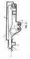
- Figure 1shows a laser printer 100 employing a replaceable sub-assembly in the form of a xerographic cassette or print cartridge 1 which is shown in greater detail in Figures 2 and 3 .
- a xerographic imaging member in the form of an endless flexible photoreceptor beltis housed within the CRU print cartridge 1, together with other xerographic process means as described below.
- a raster output scanner (ROS) 2provides an imaging beam 3 which is directed at the photoreceptor belt through an imaging slit in the CRU 1 to form an electrostatic latent image on the belt. The image is developed within the cassette and is transferred, at a transfer station 4, to a copy sheet which is fed to that location from one of four supply trays 5, 6, 7 and 8.
- the transferred imageis fused to the copy sheet at a fusing station 9 and the copy sheet may then be delivered from the printer to be collected either in a sample tray 10 on top of the machine or in a stacking tray on the side of the machine.
- a copy sheet with a fused image on one sideonly may be put into a tray-less duplex path within the machine, to be returned to the transfer station 4 to receive an image on the other side before being delivered from the machine into one of the trays 10, 11.
- the raster output scanner 2incorporates a laser to generate the imaging beam 3, a conventional rotating polygon device to sweep the beam across the surface of the photoreceptor belt, and an acoustic modulator.
- the beamis modulated in accordance with input signals received from a remote image source, for example, a user interface and keyboard (not shown).
- a remote image sourcefor example, a user interface and keyboard (not shown).
- the operation of a raster output scanner of that type to generate a latent image on a photoreceptoris well understood and need not be described here.
- the processing of the image signals from the remote sourceis handled by an electronic sub-system of the printer, indicated at 15, while operation of the printer generally is under the control of a machine control unit or CPU (not shown here), which includes one or more microprocessors and suitable memories for holding the machine operating software.
- the cassette 1may be similar to that described in U.S. Pat. No. 4,827,308 .
- the photoreceptor belt 20as depicted in Figure 2 , it includes a charge scorotron 21, a developer device 22, a transfer corotron 23, a cleaning device 24, and developer housing 25.
- the charge scorotron 21is located upstream of the imaging slit in the cassette to deposit a uniform electrostatic charge on the surface of the belt before it is exposed to the imaging beam 3.
- the developer device 22is located downstream of the imaging slit to bring developer mixture into proximity with, and thereby develop, the electrostatic latent image on the belt.
- the developer mixtureis a two-component mixture comprising toner and a magnetically-attractable carrier.
- Toneris transferred to the belt 20 during image development and replacement toner is dispensed periodically from a hopper (not shown) into the housing of the developer device 22.
- the transfer corotron 23is located at the transfer station 4 to assist in transferring the developed image from the belt to the copy sheet which enters the cassette at that point.
- the cleaning device 24removes any residual toner particles from the surface of the photoreceptor belt which is then illuminated by a discharge lamp to remove any electrostatic charge remaining on the belt.
- the CRU print cartridge 1is removable from the printer and can be replaced by another CRU if any of the process elements located therein begin to deteriorate.
- the print cartridge 1has a memory chip 30, as shown in Figure 3 , in the form of an EEPROM (Electrically Erasable Programmable Read Only Memory) mounted in the top cover of the cartridge.
- EEPROMElectrically Erasable Programmable Read Only Memory
- Contact pads 31are provided on the chip so that, when the print cartridge CRU 1 is inserted into the printer, the chip is automatically connected to the machine control unit/CPU via a terminal block 32 on a part 33 of the printer.
- the memory 30receives information from the printer control unit/CPU.
- the memoryis preferably of a non-volatile type of memory such as the EEPROM discussed above.
- non-volatile memorythere are many different ways to effect non-volatile memory and all those ways are within the contemplation of the present invention.
- conventional ROMRead Only Memory
- ROMRead Only Memory
- the combinationmay for all practical purposes effect a non-volatile memory as far as the useful life of the CRU is concerned.
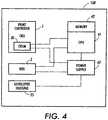
- FIG. 4there is provided a block diagram of one embodiment which may employ the teachings of the present invention.
- Machine 100while a laser printer in this example embodiment may also be a printer/copier or a fax/scanner/printer or any other such variant.
- a CPU 41which further comprises its own memory 42 either on the same chip-die or locally off-chip.
- Memory 42may include bit maps and other stored parameters for use in setpoints utilized within machine 100.
- the boot sequence in memory 42 which CPU 41 invokesincludes instructions to poll any CRU's resident in machine 100.
- One example CRU as provided hereis print cartridge CRU 1.
- the CPUmay also be provided with code which continually polls for the swapping of a CRU.
- the CPUmay respond instead to an interrupt from the swapping of a CRU.
- the CPUshall poll the CRU and its CRUM for indication that there are software updates of executable instructions or new setpoints to invoke.
- One exampleis the situation where a design or manufacturing upgrade to a xerographic print cartridge 1 is made post machine 100 launch to improve photoreceptor aging characteristics. It is desired that machine 100 changes xerographic setpoints as a function of photoreceptor 20 cyclic age by way of executable instructions invoking an algorithm operational in CPU 41.
- executable instructionsthere are a number of equations provided as algorithmic software code or executable instructions as well as parameter arguments or settings distributed in the CRUM 30 as a software upgrade. This code of executable instructions and argument set are loaded into and made resident in the machine stored software for operation in CPU 41.
- the numerical constants (A,B,C,D)are stored in the print cartridge 1 CRUM 30 along with the code for the equation above and are read by the machine 100 as software as invoked by CPU 41. So if any material or mechanical upgrade is made to the print cartridge which improves the aging rate, then the constants stored in the CRUM 30 bit map would also be changed on the manufacturing line to reflect this change.
- the machine software for CPU 41is written as discussed above to read the particular sections of the CRUM 30 which hold the algorithm constants and the algorithm code as upgraded executable software code.
- the machine softwareis written to use the correct bit map information in its algorithms to update the particular look up tables which are used to set the required power supply 43 voltages or currents, and which are used to set the ROS 2 exposure within the machine 100.
- the machine 100will read the CRUM 30 bit map and automatically upgrade the requisite numbers within its look up tables which will then be used to change the requisite voltages, currents, and exposure when the machine 100 is running in order to take advantage of the new photoreceptor 20 changed aging rate.
- This inventioncan also be used to change machine setup and aging algorithms to solve problems post-launch which may or may not be related to the particular CRU 1 which contains the CRUM 30.
- a toner cartridge CRUMmay provide the above described software code updates for the operation of a print cartridge 1. This is quite desirable as toner cartridges are typically replaced much more often than printer cartridges.
- a post-launch software update or upgradecan be resident in a machine at a much earlier time than if it was distributed by a less often replaced CRU.
- the software which is installed from the CRUM 30 to the CPU 41 and its memory 42has nothing to do with the medium or media of distribution i.e. the CRU.
- the software update/upgradeis in one example to enhance the native operating system, be it for a bug fix or an improved feature set.
- itmay be an upgrade to the graphic user interface (GUI) so as to allow new menu items, hierarchically reorder menu items or improve "look and feel". It may be simply a personalized work environment optimized for a particular machine customer.
- GUIgraphic user interface
- a CRUmay also be called an ERU (Easily Replaceable Unit) which is intended to be replaced by a tech-representative or field engineer rather than a customer.
- ERUeasily Replaceable Unit
- teachings provided hereinmay be applicable to many types of machines and systems employing CRU's, including copiers, printers and multifunction scan/print/copy/fax machines or other printing apparatus alone or in combination with computer, fax, local area network and internet connection capability. All such variants are intended to be encompassed by the following claims.
- the inventionprovides the following embodiments
Landscapes
- Physics & Mathematics (AREA)
- General Physics & Mathematics (AREA)
- Engineering & Computer Science (AREA)
- Computer Vision & Pattern Recognition (AREA)
- Control Or Security For Electrophotography (AREA)
- Accessory Devices And Overall Control Thereof (AREA)
- Electrophotography Configuration And Component (AREA)
- Stored Programmes (AREA)
- Devices For Executing Special Programs (AREA)
Abstract
Description
- The present invention relates generally to the updating of software code. The invention relates more generally to the utilization of commonly replaced system parts. The invention relates more importantly to memory provided in commonly replaced system parts. The invention relates in particular with regards to a Customer Replaceable Unit (CRU) and a Customer Replaceable Unit Monitor (CRUM).
- Many machines have replaceable sub-assemblies. Printing machines for example may have a number of replaceable sub-assemblies such as the fuser print cartridge, a toner cartridge, or an automatic document handler. These subassemblies may be arranged as unit called a cartridge, and if intended for replacement by the customer or machine owner, may be referred to as a CRU. Examples of a CRU may include printer cartridge, toner cartridge, or transfer assembly unit. It may be desirable for a CRU design to vary over the course of time due to manufacturing changes or to solve post launch problems with either: the machine, the CRU, or a CRU and machine interaction. Further, design optimizations may be recognized subsequent to design launch and machine sale, that a relatively simple code update might realize. However, solving these problems, or providing optimization updates, generally requires a field call to accomplish.
- In
U.S. Patent No. 4,496,237 to Schron , the invention described discloses a reproduction machine having a non-volatile memory for storing indications of machine consumable usage such as photoreceptor, exposure lamp and developer, and an alphanumeric display for displaying indications of such usage. In operation, a menu of categories of machine components is first scrolled on the alphanumeric display. Scrolling is provided by repetitive actuation of a scrolling switch. Having selected a desired category of components to be monitored by appropriate keyboard entry, the subcomponents of the selected category can be scrolled on the display. In this manner, the status of various consumables can be monitored and appropriate instructions displayed for replacement. In another feature, the same information on the alphanumeric display can be remotely transmitted. - In
U.S. Patent No. 4,961,088 to Gilliland et al. , there is disclosed a monitor/warranty system for electrostatographic reproducing machines in which replaceable cartridges providing a predetermined number of images are used, each cartridge having an EEPROM programmed with a cartridge identification number that when matched with a cartridge identification number in the machine enables machine operation, a cartridge replacement warning count, and a termination count at which the cartridge is disabled from further use, the EEPROM storing updated counts of the remaining number of images left on the cartridge after each print run. U.S. Patent No. 5,272,503 to LeSueur et al. , provides a printing machine, having operating parameters associated therewith, for producing prints. The printing machine includes a controller for controlling the operating parameters and an operator replaceable sub-assembly adapted to serve as a processing station in the printing machine. The operator replaceable sub-assembly includes a memory device, communicating with the controller when the replaceable sub-assembly is coupled with the printing machine, for storing a value which varies as a function of the usage of the replaceable sub-assembly, the controller adjusting a selected one of the operating parameters in accordance with the stored value for maintaining printing quality of the printing machine.U.S. Patent No. 6,016,409 to Beard et al. , there is disclosed a fuser module, being a fuser subsystem installable in a xerographic printing apparatus, which includes an electronically-readable memory permanently associated therewith. The control system of the printing apparatus reads out codes from the electronically-readable memory at install to obtain parameters for operating the module, such as maximum web use, voltage and temperature requirements, and thermistor calibration parameters.- All of the patents indicated above are herein incorporated by reference in their entirety for their teaching.
- Therefore, as discussed above, there exists a need for an arrangement and methodology which will solve the problem of providing software code updates without the need for a field service call. Thus, it would be desirable to solve this and other deficiencies and disadvantages as discussed above with an improved methodology for updating machine software code.
- The present invention relates to a method for operating a machine comprising the steps of providing a replaceable sub-assembly separable from the machine, the replaceable sub-assembly further comprising a memory, the memory having stored within it a software code upgrade of executable instructions relating to the utilization of the replaceable sub-assembly. This is then followed by placing the replaceable sub-assembly into the machine, reading the memory and placing the stored software code upgrade into the machine as new executable instructions. The final step being operating the machine with the replaceable sub-assembly in accordance with the new executable instructions.
- The present invention relates to a replaceable sub-assembly for use in a machine at various setpoints. The replaceable sub-assembly comprising a memory and upgraded executable instructions suitable for directing the machine to use the replaceable sub-assembly with different setpoints, where the upgraded executable instructions are stored in the memory.
- In one embodiment the machine is a printing apparatus.
In a further embodiment the replaceable sub-assembly is a CRU.
In a further embodiment the memory is non-volatile memory.
In a further embodiment the memory is a CRUM.
In a further embodiment the CRU is a print cartridge.
In a further embodiment the CRU is a toner cartridge. - In particular, the present invention relates to a method for operating a printer apparatus comprising the step of providing a customer replaceable unit separable from the printer apparatus, the customer replaceable unit further comprising a memory, the memory having stored within a software code upgrade of executable instructions relating to the utilization of the customer replaceable unit.
- In one embodiment of the method defined in
claim 10 the method further comprises the step of operating the printer apparatus in accordance with the software code upgrade of executable instructions.
In a further embodiment the method further comprises the steps of: - reading the CRUM and placing the stored software code upgrade of executable instructions into the printer apparatus as new executable instructions; and
- operating the printer apparatus in accordance with the new executable instructions.
FIGURE 1 depicts schematical representation of a printing machine.FIGURE 2 depicts a cross-sectional view of a replaceable sub-assembly or CRU for the machine ofFigure 1 .FIGURE 3 is a perspective view of the CRU ofFigure 2 in which the connection of the replaceable CRU to the printing machine is shown by way of a partial view.FIGURE 4 is a block diagram of the various elements in a machine and their interoperable relationships in fidelity with the teachings of the present invention.- By providing additional storage in a replaceable unit or cartridge or CRU and taking proper advantage of that storage or storage already extant, various problems associated with post launch optimization and updates may be accommodated.
- By expanding the use of the CRUM memory, a machine, if equipped according to the teachings provided herein, may be availed of software updates that while not requiring immediate installation, never-the-less remain eminently desirable. In effect the CRUM or other cartridge memory becomes the media and medium of distribution for new code installation or updates.
- While the present invention will hereinafter be described in connection with a preferred embodiment thereof, it will be understood that it is not intended to limit the invention to that embodiment. On the contrary, it is intended to cover all alternatives, modifications and equivalents as may be included within the spirit and scope of the invention as defined by the appended claims.
Figure 1 shows alaser printer 100 employing a replaceable sub-assembly in the form of a xerographic cassette orprint cartridge 1 which is shown in greater detail inFigures 2 and3 . A xerographic imaging member in the form of an endless flexible photoreceptor belt is housed within theCRU print cartridge 1, together with other xerographic process means as described below. A raster output scanner (ROS) 2 provides animaging beam 3 which is directed at the photoreceptor belt through an imaging slit in theCRU 1 to form an electrostatic latent image on the belt. The image is developed within the cassette and is transferred, at atransfer station 4, to a copy sheet which is fed to that location from one of foursupply trays sample tray 10 on top of the machine or in a stacking tray on the side of the machine. Alternatively, a copy sheet with a fused image on one side only may be put into a tray-less duplex path within the machine, to be returned to thetransfer station 4 to receive an image on the other side before being delivered from the machine into one of thetrays - The
raster output scanner 2 incorporates a laser to generate theimaging beam 3, a conventional rotating polygon device to sweep the beam across the surface of the photoreceptor belt, and an acoustic modulator. The beam is modulated in accordance with input signals received from a remote image source, for example, a user interface and keyboard (not shown). The operation of a raster output scanner of that type to generate a latent image on a photoreceptor is well understood and need not be described here. The processing of the image signals from the remote source is handled by an electronic sub-system of the printer, indicated at 15, while operation of the printer generally is under the control of a machine control unit or CPU (not shown here), which includes one or more microprocessors and suitable memories for holding the machine operating software. - The
cassette 1 may be similar to that described inU.S. Pat. No. 4,827,308 . In addition to thephotoreceptor belt 20 as depicted inFigure 2 , it includes acharge scorotron 21, adeveloper device 22, atransfer corotron 23, acleaning device 24, anddeveloper housing 25. Thecharge scorotron 21 is located upstream of the imaging slit in the cassette to deposit a uniform electrostatic charge on the surface of the belt before it is exposed to theimaging beam 3. Thedeveloper device 22 is located downstream of the imaging slit to bring developer mixture into proximity with, and thereby develop, the electrostatic latent image on the belt. The developer mixture is a two-component mixture comprising toner and a magnetically-attractable carrier. Toner is transferred to thebelt 20 during image development and replacement toner is dispensed periodically from a hopper (not shown) into the housing of thedeveloper device 22. Thetransfer corotron 23 is located at thetransfer station 4 to assist in transferring the developed image from the belt to the copy sheet which enters the cassette at that point. Finally, thecleaning device 24 removes any residual toner particles from the surface of the photoreceptor belt which is then illuminated by a discharge lamp to remove any electrostatic charge remaining on the belt. - The
CRU print cartridge 1, as already mentioned, is removable from the printer and can be replaced by another CRU if any of the process elements located therein begin to deteriorate. Theprint cartridge 1 has amemory chip 30, as shown inFigure 3 , in the form of an EEPROM (Electrically Erasable Programmable Read Only Memory) mounted in the top cover of the cartridge. Contactpads 31 are provided on the chip so that, when theprint cartridge CRU 1 is inserted into the printer, the chip is automatically connected to the machine control unit/CPU via aterminal block 32 on apart 33 of the printer. When inserted in the printer, thememory 30 receives information from the printer control unit/CPU. The memory is preferably of a non-volatile type of memory such as the EEPROM discussed above. It will be well understood that there are many different ways to effect non-volatile memory and all those ways are within the contemplation of the present invention. For example, conventional ROM (Read Only Memory) is typically volatile and will lose the data contents of its cells when power is removed. However, if ROM is provided with a long life battery on the CRU and if the ROM is of sufficiently low power dissipation, the combination may for all practical purposes effect a non-volatile memory as far as the useful life of the CRU is concerned. - In
Figure 4 , there is provided a block diagram of one embodiment which may employ the teachings of the present invention.Machine 100 while a laser printer in this example embodiment may also be a printer/copier or a fax/scanner/printer or any other such variant. Withinmachine 100 is aCPU 41 which further comprises itsown memory 42 either on the same chip-die or locally off-chip.Memory 42 may include bit maps and other stored parameters for use in setpoints utilized withinmachine 100. At power up subsequent to whenpower supply 43 is switched on, the boot sequence inmemory 42 whichCPU 41 invokes, includes instructions to poll any CRU's resident inmachine 100. One example CRU as provided here isprint cartridge CRU 1. AsCPU 41 polls replaceable units it checks for indication that there are software updates or tags to invoke. There could be lines of software code or other executable instruction to be read in and substituted. Or in one alternative there may just be a tag indicia that different lines of code or lookup tables (LUT) are to be invoked in the operation of themachine 100. The tag could be as simple as the setting of a single bit or it could be an address pointing to the location of data, lines of code/ executable instructions, or a LUT with lines of code/executable instructions. In all of these possible scenarios above and which follow below, the indicator is one which is shipped with the CRU at time of manufacture or point of distribution. - The CPU may also be provided with code which continually polls for the swapping of a CRU. In an alternative obvious to one skilled in the art, the CPU may respond instead to an interrupt from the swapping of a CRU. In either case upon determination of a swapped or new CRU the CPU shall poll the CRU and its CRUM for indication that there are software updates of executable instructions or new setpoints to invoke.
- One example is the situation where a design or manufacturing upgrade to a
xerographic print cartridge 1 is madepost machine 100 launch to improve photoreceptor aging characteristics. It is desired thatmachine 100 changes xerographic setpoints as a function ofphotoreceptor 20 cyclic age by way of executable instructions invoking an algorithm operational inCPU 41. For this embodiment there are a number of equations provided as algorithmic software code or executable instructions as well as parameter arguments or settings distributed in theCRUM 30 as a software upgrade. This code of executable instructions and argument set are loaded into and made resident in the machine stored software for operation inCPU 41. These equations are utilized to calculate theprint cartridge 1 charge voltage, thedeveloper housing 25 bias voltage and theROS 2 imaging exposure level as a function ofphotoreceptor 20 age in cycles ofmachine 100 temperature andmachine 100 humidity. These equations as manifest in upgraded executable instruction code contain a number of numerical constants which are tied to thephotoreceptor 20 aging rate, temperature and humidity. One example embodiment of such interaction of setpoints and algorithm is found in the operation of the following equation for the ROS exposure:
- In order to implement a manufacturing change which impacts the aging rate, it would be required to make a change to parameter C. If the photosensitivity to temperature or humidity changes, then the A or B setpoints would change. If the overall photosensitivity changed, then D would need to change.
- It is necessary to change the machine system software to accommodate these changes. For machines already in the field this may be normally be too prohibitive in cost. With this invention the numerical constants (A,B,C,D) are stored in the
print cartridge 1CRUM 30 along with the code for the equation above and are read by themachine 100 as software as invoked byCPU 41. So if any material or mechanical upgrade is made to the print cartridge which improves the aging rate, then the constants stored in theCRUM 30 bit map would also be changed on the manufacturing line to reflect this change. To enable the teaching provided herein of this invention, the machine software forCPU 41 is written as discussed above to read the particular sections of theCRUM 30 which hold the algorithm constants and the algorithm code as upgraded executable software code. Also the machine software is written to use the correct bit map information in its algorithms to update the particular look up tables which are used to set the requiredpower supply 43 voltages or currents, and which are used to set theROS 2 exposure within themachine 100. When the upgradedprint cartridge 1 is installed into themachine 100, themachine 100 will read theCRUM 30 bit map and automatically upgrade the requisite numbers within its look up tables which will then be used to change the requisite voltages, currents, and exposure when themachine 100 is running in order to take advantage of thenew photoreceptor 20 changed aging rate. - This invention can also be used to change machine setup and aging algorithms to solve problems post-launch which may or may not be related to the
particular CRU 1 which contains theCRUM 30. For example, a toner cartridge CRUM may provide the above described software code updates for the operation of aprint cartridge 1. This is quite desirable as toner cartridges are typically replaced much more often than printer cartridges. Thus, a post-launch software update or upgrade can be resident in a machine at a much earlier time than if it was distributed by a less often replaced CRU. - Indeed, in one embodiment the software which is installed from the
CRUM 30 to theCPU 41 and itsmemory 42 has nothing to do with the medium or media of distribution i.e. the CRU. Instead, the software update/upgrade is in one example to enhance the native operating system, be it for a bug fix or an improved feature set. In another example, it may be an upgrade to the graphic user interface (GUI) so as to allow new menu items, hierarchically reorder menu items or improve "look and feel". It may be simply a personalized work environment optimized for a particular machine customer. The variations achievable are, as will be understood by those skilled in the art, limited only by the storage size of the CRUM or other CRU memory, and the operational boundaries and feature set of the machine. - In closing, by employing the CRUM or other CRU memory as the media and the distribution of replaceable cartridges or customer replaceable units as a medium of software distribution, software updates/upgrades may be readily distributed from the factory or other central point of distribution post-launch of the target machine without the need for a field service call. Thereby, application of this methodology will allow appropriate software replacement schedules to be instituted for updates/upgrades which minimize both cost and customer down time.
- While the embodiments disclosed herein are preferred, it will be appreciated from this teaching that various alternative modifications, variations or improvements therein may be made by those skilled in the art. A CRU may also be called an ERU (Easily Replaceable Unit) which is intended to be replaced by a tech-representative or field engineer rather than a customer. Further, it will be understood by those skilled in the art that the teachings provided herein may be applicable to many types of machines and systems employing CRU's, including copiers, printers and multifunction scan/print/copy/fax machines or other printing apparatus alone or in combination with computer, fax, local area network and internet connection capability. All such variants are intended to be encompassed by the following claims.
- According to a further aspect, the invention provides the following embodiments
- 1. A method for operating a machine comprising the steps of:
- providing a replaceable sub-assembly separable from the machine, the replaceable sub-assembly further comprising a memory, the memory having stored within a software code upgrade of executable instructions relating to the utilization of the replaceable sub-assembly;
- placing the replaceable sub-assembly into the machine;
- reading the memory and placing the stored software code upgrade into the machine as new executable instructions; and
- operating the machine with the replaceable sub-assembly in accordance with the new executable instructions.
- 2. The method of
embodiment 1 wherein the machine is a printing apparatus. - 3. The method of
embodiment 2 wherein the replaceable sub-assembly is a CRU. - 4. The method of
embodiment 3 wherein the memory is a non-volatile type of memory. - 5. The method of
embodiment 4 wherein the memory is a CRUM. - 6. The method of
embodiment 2 wherein the software code upgrade of executable instructions includes parameter arguments. - 7. A replaceable sub-assembly for use in a machine at various setpoints comprising:
- a memory; and
- upgraded executable instruction suitable for directing the machine to use the replaceable sub-assembly with different setpoints, where the upgraded executable instruction is stored in the memory.
- 8. A method for operating a printer apparatus comprising the step of:
- providing a customer replaceable unit separable from the printer apparatus, the customer replaceable unit further comprising a memory, the memory having stored within a software code upgrade of executable instructions relating to the utilization of the customer replaceable unit.
- 9. The method of
embodiment 8 wherein the memory is non-volatile in type. - 10. The method of embodiment 9 wherein the memory is a CRUM.
In a further embodiment the customer replaceable unit is a toner cartridge.
In a further embodiment the software code upgrade of executable instructions includes parameter arguments.

Claims (8)
- A method for operating a printer apparatus comprising the step of:providing a customer replaceable unit separable from the printer apparatus, the customer replaceable unit further comprising a memory, thememory having stored within a software code upgrade of executable instructions relating to the utilization of the customer replaceable unit.
- The method of claim 8 wherein the memory is non-volatile in type.
- The method of claim 9 wherein the memory is a CRUM.
- The method defined in claim 3 further comprising the step of operating the printer apparatus in accordance with the software code upgrade of executable instructions.
- The method of claim 3 further comprising the steps of:reading the CRUM and placing the stored software code upgrade of executable instructions into the printer apparatus as new executable instructions; andoperating the printer apparatus in accordance with the new executable instructions.
- The method of claim 3, wherein
the customer replaceable unit is a printer cartridge. - The method of claim 3, wherein
the customer replaceable unit is a toner cartridge. - The method of claim 3, wherein
the software code upgrade of executable instructions includes parameter arguments.
Applications Claiming Priority (2)
| Application Number | Priority Date | Filing Date | Title |
|---|---|---|---|
| US10/151,121US6735399B2 (en) | 2002-05-17 | 2002-05-17 | Post-launch process optimization of replaceable sub-assembly utilization through customer replaceable unit memory programming |
| EP03011267AEP1363170A3 (en) | 2002-05-17 | 2003-05-16 | Post-launch process optimization of replaceable subassembly utilization through customer replaceable unit memory programming |
Related Parent Applications (2)
| Application Number | Title | Priority Date | Filing Date |
|---|---|---|---|
| EP03011267.6Division | 2003-05-16 | ||
| EP03011267ADivisionEP1363170A3 (en) | 2002-05-17 | 2003-05-16 | Post-launch process optimization of replaceable subassembly utilization through customer replaceable unit memory programming |
Publications (2)
| Publication Number | Publication Date |
|---|---|
| EP2479621A2true EP2479621A2 (en) | 2012-07-25 |
| EP2479621A3 EP2479621A3 (en) | 2016-12-07 |
Family
ID=29269806
Family Applications (2)
| Application Number | Title | Priority Date | Filing Date |
|---|---|---|---|
| EP03011267ACeasedEP1363170A3 (en) | 2002-05-17 | 2003-05-16 | Post-launch process optimization of replaceable subassembly utilization through customer replaceable unit memory programming |
| EP12159496.4AWithdrawnEP2479621A3 (en) | 2002-05-17 | 2003-05-16 | Post-launch process optimization of replaceable sub-assembly utilization through customer replaceable unit memory programming |
Family Applications Before (1)
| Application Number | Title | Priority Date | Filing Date |
|---|---|---|---|
| EP03011267ACeasedEP1363170A3 (en) | 2002-05-17 | 2003-05-16 | Post-launch process optimization of replaceable subassembly utilization through customer replaceable unit memory programming |
Country Status (3)
| Country | Link |
|---|---|
| US (2) | US6735399B2 (en) |
| EP (2) | EP1363170A3 (en) |
| JP (1) | JP2004001512A (en) |
Families Citing this family (35)
| Publication number | Priority date | Publication date | Assignee | Title |
|---|---|---|---|---|
| US6724895B1 (en) | 1998-06-18 | 2004-04-20 | Supersensor (Proprietary) Limited | Electronic identification system and method with source authenticity verification |
| EP1247221A4 (en) | 1999-09-20 | 2005-01-19 | Quintiles Transnat Corp | System and method for analyzing de-identified health care data |
| US7137000B2 (en) | 2001-08-24 | 2006-11-14 | Zih Corp. | Method and apparatus for article authentication |
| US7577578B2 (en)* | 2001-12-05 | 2009-08-18 | Ims Software Services Ltd. | Method for determining the post-launch performance of a product on a market |
| US6735399B2 (en)* | 2002-05-17 | 2004-05-11 | Xerox Corporation | Post-launch process optimization of replaceable sub-assembly utilization through customer replaceable unit memory programming |
| US7239413B2 (en)* | 2002-10-29 | 2007-07-03 | Hewlett-Packard Development Company, L.P. | Printer replaceable component |
| US20040145615A1 (en)* | 2003-01-29 | 2004-07-29 | Castro Eugene Villa | Printing/scanning device entitlement monitoring system |
| US7321966B2 (en)* | 2003-05-29 | 2008-01-22 | Xerox Corporation | Machine post-launch configuration and option upgrade |
| US20040239979A1 (en)* | 2003-05-29 | 2004-12-02 | Parry Travis J. | Method and systems for providing an email engine for a printing device |
| US7043166B2 (en)* | 2003-07-08 | 2006-05-09 | Hewlett-Packard Development Company, L.P. | Methods and systems for providing firmware to a printing device |
| US8682978B2 (en)* | 2003-07-09 | 2014-03-25 | Hewlett-Packard Development Company, L.P. | Methods and systems for providing email messages to a printing device |
| US7197633B2 (en)* | 2003-07-30 | 2007-03-27 | Xerox Corporation | Wireless machine post-launch configuration and option upgrade |
| US7334261B2 (en)* | 2003-07-30 | 2008-02-19 | Xerox Corporation | Machine post-launch configuration and option upgrade with master key |
| US7497536B2 (en)* | 2004-04-19 | 2009-03-03 | Hewlett-Packard Development Company, L.P. | Fluid ejection device |
| ATE523276T1 (en)* | 2004-04-30 | 2011-09-15 | Sumitomo Electric Industries | METHOD FOR PRODUCING CHAIN METAL POWDERS, CHAIN METAL POWDERS PRODUCED THEREFROM AND ANISOTROPIC CONDUCTIVE FILMS PRODUCED BY USING THE POWDER |
| US9296214B2 (en) | 2004-07-02 | 2016-03-29 | Zih Corp. | Thermal print head usage monitor and method for using the monitor |
| US7344212B2 (en)* | 2004-08-16 | 2008-03-18 | Lexmark International, Inc. | Imaging apparatus having a programmable throughput rate |
| KR100636191B1 (en)* | 2004-11-13 | 2006-10-19 | 삼성전자주식회사 | Checking system and method for compatibility of component units |
| KR100577715B1 (en) | 2004-12-01 | 2006-05-10 | 삼성전자주식회사 | Image forming apparatus and control method thereof |
| KR100793955B1 (en)* | 2004-12-03 | 2008-01-16 | 삼성전자주식회사 | An image forming apparatus, a host apparatus connected thereto, an image forming system including the same, and a control method thereof |
| US7231153B2 (en)* | 2005-01-13 | 2007-06-12 | Xerox Corporation | Systems and methods for monitoring replaceable units |
| JP4970780B2 (en)* | 2005-03-09 | 2012-07-11 | 株式会社リコー | Electronic device and exchange unit |
| US8271387B2 (en) | 2005-06-20 | 2012-09-18 | Intraware, Inc. | Method and apparatus for providing limited access to data objects or files within an electronic software delivery and management system |
| US20060288009A1 (en)* | 2005-06-20 | 2006-12-21 | Tobid Pieper | Method and apparatus for restricting access to an electronic product release within an electronic software delivery system |
| US8917159B2 (en)* | 2005-08-19 | 2014-12-23 | CLARKE William McALLISTER | Fully secure item-level tagging |
| JP4319176B2 (en)* | 2005-08-23 | 2009-08-26 | シャープ株式会社 | Network system including customer replaceable units |
| US7319829B2 (en)* | 2005-08-26 | 2008-01-15 | Lexmark International, Inc. | Transfer bias adjustment based on component life |
| US8721203B2 (en)* | 2005-10-06 | 2014-05-13 | Zih Corp. | Memory system and method for consumables of a printer |
| US7769306B2 (en)* | 2005-12-30 | 2010-08-03 | Lexmark International, Inc. | Storing printer density control parameters in cartridge memory |
| US7466932B2 (en)* | 2006-03-21 | 2008-12-16 | Kabushiki Kaisha Toshiba | Image forming method with renewal of toner residual amount |
| US9355273B2 (en) | 2006-12-18 | 2016-05-31 | Bank Of America, N.A., As Collateral Agent | System and method for the protection and de-identification of health care data |
| US20090110417A1 (en) | 2007-10-29 | 2009-04-30 | Kabushiki Kaisha Toshiba | Image forming apparatus |
| KR100933290B1 (en)* | 2008-02-22 | 2009-12-22 | 삼성전자주식회사 | A memory unit, a developer cartridge, a developing apparatus and an image forming apparatus including the same |
| KR100997238B1 (en)* | 2008-03-03 | 2010-11-29 | 삼성전자주식회사 | CRUM unit, replaceable unit and image forming apparatus using same, authentication and encryption data communication method thereof |
| US11919313B2 (en)* | 2018-12-04 | 2024-03-05 | Hewlett-Packard Development Company, L.P. | Print device functionalities |
Citations (5)
| Publication number | Priority date | Publication date | Assignee | Title |
|---|---|---|---|---|
| US4496237A (en) | 1982-08-09 | 1985-01-29 | Xerox Corporation | Consumable status display |
| US4827308A (en) | 1986-12-15 | 1989-05-02 | Xerox Corporation | Process unit for an imaging apparatus |
| US4961088A (en) | 1989-04-20 | 1990-10-02 | Xerox Corporation | Monitor/warranty system for electrostatographic reproducing machines using replaceable cartridges |
| US5272503A (en) | 1992-09-02 | 1993-12-21 | Xerox Corporation | Replaceable sub-assemblies for electrostatographic reproducing machines |
| US6016409A (en) | 1997-04-11 | 2000-01-18 | Xerox Corporation | System for managing fuser modules in a digital printing apparatus |
Family Cites Families (8)
| Publication number | Priority date | Publication date | Assignee | Title |
|---|---|---|---|---|
| US5699091A (en)* | 1994-12-22 | 1997-12-16 | Hewlett-Packard Company | Replaceable part with integral memory for usage, calibration and other data |
| US5930553A (en)* | 1997-04-25 | 1999-07-27 | Hewlett-Packard Company | Image forming and office automation device consumable with memory |
| US6173128B1 (en)* | 1999-08-27 | 2001-01-09 | Xerox Corporation | Remanufacturing system for replaceable modules in a digital printing apparatus |
| JP4365951B2 (en)* | 1999-09-09 | 2009-11-18 | キヤノン株式会社 | Image forming apparatus |
| US6351621B1 (en)* | 2000-06-26 | 2002-02-26 | Xerox Corporation | Wireless interaction with memory associated with a replaceable module for office equipment |
| US6351618B1 (en)* | 2000-12-20 | 2002-02-26 | Xerox Corporation | Method of using a security system for replaceable cartridges for printing machines |
| US6459860B1 (en)* | 2001-03-08 | 2002-10-01 | Hewlett-Packard Company | Replaceable printer component including memory device that defines printing capabilities |
| US6735399B2 (en)* | 2002-05-17 | 2004-05-11 | Xerox Corporation | Post-launch process optimization of replaceable sub-assembly utilization through customer replaceable unit memory programming |
- 2002
- 2002-05-17USUS10/151,121patent/US6735399B2/ennot_activeExpired - Lifetime
- 2003
- 2003-05-14JPJP2003135344Apatent/JP2004001512A/enactivePending
- 2003-05-16EPEP03011267Apatent/EP1363170A3/ennot_activeCeased
- 2003-05-16EPEP12159496.4Apatent/EP2479621A3/ennot_activeWithdrawn
- 2003-11-25USUS10/722,152patent/US20040141763A1/ennot_activeAbandoned
Patent Citations (5)
| Publication number | Priority date | Publication date | Assignee | Title |
|---|---|---|---|---|
| US4496237A (en) | 1982-08-09 | 1985-01-29 | Xerox Corporation | Consumable status display |
| US4827308A (en) | 1986-12-15 | 1989-05-02 | Xerox Corporation | Process unit for an imaging apparatus |
| US4961088A (en) | 1989-04-20 | 1990-10-02 | Xerox Corporation | Monitor/warranty system for electrostatographic reproducing machines using replaceable cartridges |
| US5272503A (en) | 1992-09-02 | 1993-12-21 | Xerox Corporation | Replaceable sub-assemblies for electrostatographic reproducing machines |
| US6016409A (en) | 1997-04-11 | 2000-01-18 | Xerox Corporation | System for managing fuser modules in a digital printing apparatus |
Also Published As
| Publication number | Publication date |
|---|---|
| US6735399B2 (en) | 2004-05-11 |
| EP1363170A2 (en) | 2003-11-19 |
| EP1363170A3 (en) | 2006-02-08 |
| JP2004001512A (en) | 2004-01-08 |
| EP2479621A3 (en) | 2016-12-07 |
| US20030215246A1 (en) | 2003-11-20 |
| US20040141763A1 (en) | 2004-07-22 |
Similar Documents
| Publication | Publication Date | Title |
|---|---|---|
| US6735399B2 (en) | Post-launch process optimization of replaceable sub-assembly utilization through customer replaceable unit memory programming | |
| EP1363172A2 (en) | Machine post-launch process optimization through customer replaceable unit memory programming | |
| JP3689475B2 (en) | Process cartridge, developing device, and electrophotographic image forming apparatus | |
| JP2001083862A (en) | Image forming device | |
| US20070033585A1 (en) | Electronic appliance | |
| EP0913737B1 (en) | Image forming apparatus, and recycle processing apparatus for recycling image forming unit | |
| EP0532308B1 (en) | Replaceable sub-assemblies for electrostatographic reproducing machines | |
| JP2004013025A (en) | Image forming apparatus, method of replacing consumable member thereof, and replacement system | |
| EP1363171A2 (en) | post-launch process optimization of replaceable sub-assembly utilization through customer replaceable unit memory programming provided in an alternate replaceable sub-assembly | |
| US8014012B2 (en) | Software upgrades from a printer module with on-board intelligence | |
| US7224912B2 (en) | Method of providing device usage data | |
| EP1184734B1 (en) | Image forming device | |
| KR100542356B1 (en) | Method for controlling setting sheet of image forming apparatus and apparatus therefor | |
| JPH11153929A (en) | Electrophotographic equipment | |
| WO2020194833A1 (en) | Image forming apparatus | |
| JP2004133769A (en) | Image forming apparatus control module generation apparatus and generation method thereof | |
| JP7275753B2 (en) | image forming device | |
| CN111984205B (en) | Information management system, information management method, and cartridge | |
| JP2004354922A (en) | Information management apparatus and information management method for image forming apparatus | |
| JP2006201486A (en) | Image forming apparatus | |
| JP2001296775A (en) | Image forming device | |
| JPH04190366A (en) | electrophotographic equipment | |
| JPH0486280A (en) | image forming device | |
| JP2000206838A (en) | Image forming apparatus and process cartridge | |
| JP2005091964A (en) | Image forming apparatus |
Legal Events
| Date | Code | Title | Description |
|---|---|---|---|
| PUAI | Public reference made under article 153(3) epc to a published international application that has entered the european phase | Free format text:ORIGINAL CODE: 0009012 | |
| AC | Divisional application: reference to earlier application | Ref document number:1363170 Country of ref document:EP Kind code of ref document:P | |
| AK | Designated contracting states | Kind code of ref document:A2 Designated state(s):DE FR GB | |
| PUAL | Search report despatched | Free format text:ORIGINAL CODE: 0009013 | |
| AK | Designated contracting states | Kind code of ref document:A3 Designated state(s):DE FR GB | |
| RIC1 | Information provided on ipc code assigned before grant | Ipc:G03G 21/18 20060101AFI20161031BHEP Ipc:G03G 21/16 20060101ALI20161031BHEP | |
| STAA | Information on the status of an ep patent application or granted ep patent | Free format text:STATUS: THE APPLICATION IS DEEMED TO BE WITHDRAWN | |
| 18D | Application deemed to be withdrawn | Effective date:20170608 |