EP2478650B1 - Apparatus and method for generating high resolution frames for dimming and visibility support in visible light communication - Google Patents
Apparatus and method for generating high resolution frames for dimming and visibility support in visible light communicationDownload PDFInfo
- Publication number
- EP2478650B1 EP2478650B1EP10817415.2AEP10817415AEP2478650B1EP 2478650 B1EP2478650 B1EP 2478650B1EP 10817415 AEP10817415 AEP 10817415AEP 2478650 B1EP2478650 B1EP 2478650B1
- Authority
- EP
- European Patent Office
- Prior art keywords
- visibility
- low resolution
- resolution frames
- pattern
- frames
- Prior art date
- Legal status (The legal status is an assumption and is not a legal conclusion. Google has not performed a legal analysis and makes no representation as to the accuracy of the status listed.)
- Active
Links
Images


Classifications
- H—ELECTRICITY
- H04—ELECTRIC COMMUNICATION TECHNIQUE
- H04B—TRANSMISSION
- H04B10/00—Transmission systems employing electromagnetic waves other than radio-waves, e.g. infrared, visible or ultraviolet light, or employing corpuscular radiation, e.g. quantum communication
- H04B10/11—Arrangements specific to free-space transmission, i.e. transmission through air or vacuum
- H04B10/114—Indoor or close-range type systems
- H04B10/1149—Arrangements for indoor wireless networking of information
- H—ELECTRICITY
- H04—ELECTRIC COMMUNICATION TECHNIQUE
- H04B—TRANSMISSION
- H04B10/00—Transmission systems employing electromagnetic waves other than radio-waves, e.g. infrared, visible or ultraviolet light, or employing corpuscular radiation, e.g. quantum communication
- H04B10/11—Arrangements specific to free-space transmission, i.e. transmission through air or vacuum
- H04B10/114—Indoor or close-range type systems
- H04B10/116—Visible light communication
Definitions
- the present applicationrelates generally to visible light communication and, more specifically, to methods for generating high resolution visibility frames for visible light communication.
- Visible light communicationis a new technology for short-range optical wireless communication using visible light in optically transparent media. This technology provides access to several hundred terahertz (THz) of unlicensed spectrum. VLC is immune to the problems of electromagnetic interference and non-interference associated with radio frequency (RF) systems. VLC provides an additional level of security by allowing a user to see the transmission of data across the communication channel. Another benefit of VLC is that it augments and complements existing services (such as illumination, display, indication, decoration, etc.) from existing visible-light infrastructures.
- a VLC networkis any network of two or more devices that engage in VLC.
- FIG. 1depicts the full electromagnetic frequency spectrum, and a breakout of the wavelengths occupied by visible light.
- the visible light spectrumextends from approximately 380 to 780 nm in wavelength, which corresponds to a frequency range of approximately 400 to 790 THz. Since this spectrum is large and can support light sources with multiple colors, VLC technology can provide a large number of channels for communication.
- WO 2007/099472discloses a method for a lighting device, in particular for a display device such as a LCD-TV, projector etc., generating radiation including at least visible light for illumination with at least one light-emitting element being a LED or an OLED, emitting radiation comprising an average light intensity for illumination purpose, a controller coupled to the light-emitting element modulating said radiation for a data transfer simultaneously to the illumination purpose, wherein the controller is configured in such a way, that simultaneously data signals are transmitted via the generated radiation of said light-emitting element and said modulation is not visible by an observer, wherein the data signals are transmitted to a detecting unit.
- US 2007/109328discloses a device for controlling the brightness of a one or more LEDs that includes a modulator having at least 11 bits of pulse width modulation resolution.
- a bufferreceives pulses from the modulator.
- a drivermay be coupled to receive pulses from the buffer and drive the one or more LEDs.
- a currently limitermay be employed to prevent damage to the one or more LEDs.
- An update ratemay be selected to limit perceptible flicker of the one or more LE.
- the present inventionprovides a method and apparatus for generating high resolution frames for dimming support in a visible light communication (VLC) network.
- VLCvisible light communication
- a method for generating high resolution frames for dimming support in a visible light communication, VLCincludes identifying a required visibility pattern for the high resolution frames; generating a sequence of visibility patterns that meets the required visibility pattern, the sequence comprising a first quantity of first low resolution frames and a second quantity of second low resolution frames; and transmitting the sequence of visibility patterns to achieve the required high resolution frames, wherein a visibility pattern for the first low resolution frame and a visibility pattern for the second low resolution frame are selected based on the required visibility pattern of the high resolution frames, and wherein the first quantity of the first low resolution frames and the second quantity of the second low resolution frames are determined based on a desired precision.
- a transmittercapable of generating and transmitting high resolution frames for dimming support in a visible light communication, VLC.
- the transmitterincludes: a controller configured to: identify a required visibility pattern for the high resolution frames, and generate a sequence of visibility patterns that meets the required visibility pattern, the sequence comprising a first quantity of first low resolution frames and a second quantity of second low resolution frames; and a light source configured to transmit the sequence visibility patterns to achieve the required high resolution frames, wherein a visibility pattern for the first low resolution frame and a visibility pattern for the second low resolution frame are selected based on the required visibility pattern of the high resolution frame, and wherein the first quantity of the first low resolution frames and the second quantity of the second low resolution frames are determined based on a desired precision.
- a system for generating high resolution frames for dimming support in a visible light communication, VLCincludes a transmitter, the transmitter configured to: identify a required visibility pattern for the high resolution frames; generate a sequence of visibility patterns that meets the required visibility pattern, the sequence comprising a first quantity of first low resolution frames and a second quantity of second low resolution frames; and transmit the sequence of visibility patterns to achieve the required high resolution frames; and a receiver configured to receive data at the required visibility pattern by adapting the data reception according to the visibility pattern generated at the transmitter, wherein a visibility pattern for the first low resolution frame and a visibility pattern for the second low resolution frame are selected based on the required visibility pattern of the high resolution frames, and wherein the first quantity of the first low resolution frames and the second quantity of the second low resolution frames are determined based on a desired precision.
- the present inventionprovides a method and an apparatus for generating high resolution frames for dimming support in a visible light communication (VLC) network.
- VLCvisible light communication
- FIGURES 1 through 12discussed below, and the various embodiments used to describe the principles of the present disclosure in this patent document are by way of illustration only and should not be construed in any way to limit the scope of the disclosure. Those skilled in the art will understand that the principles of the present disclosure may be implemented in any suitably arranged visible light communication network.
- FIGURE 2depicts several exemplary applications that can be enabled by VLC.
- FIGURE 2(a)shows an example of peer-to-peer (P2P) communication.
- P2Ppeer-to-peer
- FIGURE 2(b)shows an example of another type of P2P VLC communication known as near field communication (NFC).
- NFCmay be used where the communication distance is very short ( ⁇ 30 cm or so). In NFC, very high data rates (> 100 Mbps) can be attained.
- a mobile phonecommunicates with a laptop computer using VLC.
- FIGURE 2(c)shows an example of a visible LAN (VLAN) system where the infrastructure lighting system also functions as an access point and enables LAN service to one or more devices, such as a laptop or a mobile phone.
- FIGURE 2(d)shows an example of an information broadcasting (IB) system where a display at a public location (e.g., a mall or museum) could broadcast information (e.g., information about facilities, directions, or services) using VLC. Devices (e.g., mobile phones) that are in range of the broadcast may then receive the information.
- FIGURE 2(e)shows an example of the use of VLC for vehicular broadcasting (VB) applications such as conveying safety or traffic information from traffic signals or from other cars.
- VBvehicular broadcasting
- an infrastructure light sourcee.g., overhead ambient light
- TXloss of transmission
- Continuous "ON”is also important for VLAN uplink and P2P applications that support point-and-shoot techniques to focus the light on the receiver for optimal communication (i.e., pointing).
- FIGURE 3One method for ensuring a continuous "ON" state is shown in FIGURE 3 .
- FIGURE 3depicts an idle/receiving (idle/RX) state signal that is transmitted during idle or receiving states of an infrastructure light source, according to one embodiment of the present disclosure. If a light source transmits at certain intervals, and is then idle between those intervals, visible flicker in the light source can result.
- An idle/receiving state signalcan be used to maintain optimal visibility and flicker-free operation during idle or receiving periods at the infrastructure. This is accomplished by the idle/ receiving signal mimicking the general pattern of the active transmission signal. Specifically, the idle/receiving signal has generally the same duty cycle that is used during the active signal.
- a light sourcetransmits signals 302 and 304 during two active transmission blocks.
- the active transmission blocksare separated by an idle/receiving block.
- an idle/RX state signal 306is generated to be transmitted during the idle/receiving block.
- regular output signal 308may be an infrastructure transmission output.
- regular output signal 308may be a point-and-shoot transmission output, as explained in greater detail below. Transmission of data signals during idle/RX periods in order to control visible flicker is unique to VLC. The ability to control flicker in this manner is often called visibility support.
- FIGURE 4shows a more detailed example of the need for visibility for point-and-shoot applications.
- mobile devices 402 and 403wish to communicate via VLC with access point 404, which serves as an access point for network 406.
- access point 404which serves as an access point for network 406.
- mobile device 402needs to point accurately to access point 404.
- mobile device 402needs adjustment of its beam until it points directly to access point 404. With the beam in position A, there is no communication possible. As the user moves the beam of mobile device 402 towards access point 404, the beam reaches position B. At position B, mobile device 402 may be sufficiently aligned with access point 404 such that downlink communication is possible. However, uplink communication is still not possible.
- mobile device 402In position C, mobile device 402 is substantially aligned with access point 404, enabling both uplink and downlink transmissions. However, if there are significant idle periods in the transmission, the signal strength of the beam from mobile device 402 will be very weak. Thus, a visibility pattern could be sent from mobile device 402 to assist with pointing.
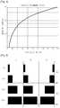
- FIGURE 5shows a graph depicting the human eye's perception of light of increasing brightness. As seen in the graph, the human eye has a non-linear response to the dimming level. At low light levels, the amount of light that a human eye perceives is greater than the actual light present in the room, based on a light measurement from a lux meter. Thus, particularly at low light levels, it is desirable to have a wide range of visibility levels that can be supported by a light source. In preferred embodiments, the dimming range of the light source may vary between 0.1 100% in order to have the visibility setting appropriate to the user's comfort.
- ECMA TC-47describes only eleven (11) different patterns for visibility. These patterns are shown in Table 1 below. As seen in the table, the visibility patterns range from 0% to 100% in increments or steps of 10%. These visibility patterns could therefore be considered low resolution patterns. ECMA TC-47 does not provide any visibility patterns at finer resolution levels, e.g., 1% or 0.1% resolution. Thus, ECMA TC-47 offers no suggestion for achieving an overall visibility of, e.g., 43% or 25.8%. Furthermore, defining distinct visibility patterns at finer resolution levels would quickly become impractical. For example, it would require at least one thousand different visibility patterns to support a full range of 0.1% resolution levels for dimming.
- VPMVariable Pulse Position Modulation
- 2-PPMPulse Position Modulation
- PWMPulse Width Modulation
- VPMmakes use of the concepts of 2-PPM for non-flicker and PWM for dimming control function and full brightness. Dimming control function and full brightness in VPM is achieved by controlling the pulse width of a VPM signal, which means the "ON" time width of a light source.
- FIGURE 6depicts dimming support in VPM by controlling the pulse width of the VPM signal. Bits “0" and “1” are distinguished by the pulse position in each period. The pulse width determines the dimming level.
- FIGURE 6depicts example dimming levels with a resolution of 10%.
- VPMcannot provide high resolution dimming because it would require the device to support an extremely high clock rate in order to obtain a fine resolution. For example, in order to get a 0.1% duty cycle resolution, the optical source would need to support a 1000X faster clock, which is not practical.
- Embodiments of the present disclosureprovide methods of generating high resolution visibility patterns for VLC.
- the high resolutionis provided without substantial complexity and without predefining and storing hundreds or thousands of different visibility patterns in memory.
- the disclosed methodsmay be used for supporting point-and-shoot, continuous infrastructure illumination, dimming, and other VLC communication.
- the disclosed methodsare also compatible with VPM communication.
- the number of transitions between 0's and 1'smay be maximized to provide high frequency switching in order to avoid flicker and to help the Clock and Data Recovery (CDR) circuit at the receiver for synchronization purposes, if used.
- CDRClock and Data Recovery
- Current low resolution visibility patternsmay have certain properties (e.g., a visibility pattern may not match any existing data pattern out of the 8b10b code). These properties may be preserved with new high resolution patterns.
- Visibility patternsshould be transmitted in order to minimize flicker and meet regulatory requirements in the presence or absence of dimming. If visibility patterns are transmitted with changing the clock frequency (in-band), the patterns that are used should avoid conflicts with existing RLL codewords.
- FIGURE 7depicts a transmitter configured to combine existing low resolution visibility patterns to create high resolution dimming patterns, according to embodiments of the present disclosure.
- Transmitter 700includes a processor/ controller 702, memory 704, and light source 706.
- Transmitter 700is coupled to network 708.
- Transmitter 700transmits to receiver 720.
- Transmitter 700through light source 706, is configured to transmit visibility patterns that are defined at 10% resolution, as indicated by reference numeral 710.
- the defined visibility patterns 710may correspond to the visibility patterns proposed in ECMA TC-47, as shown in Table 1 above.
- light source 706would alternately send a 20% visibility pattern followed by a 30% visibility pattern. This method guarantees all frames will retain the same properties as existing visibility frames. Because there are multiple ways in which this can be achieved, it is desirable to choose the way that maximizes the transitions and minimizes flicker. Other dimming patterns are possible by combining different defined visibility patterns 710 in different ways.
- the information about the required visibility level at transmitter 700is also sent to receiver 720 before the pattern is applied at transmitter 700 for dimming support.
- This informationmay be sent, for example, via a command in the medium access control layer (MAC).
- Receiver 720uses this information to know the transmitter pattern generated for dimming support. When transmitter 700 applies this pattern for data communication, receiver 720 also adapts the data reception according to the generated transmitter pattern for successful data communication.
- MACmedium access control layer
- VPM communicationunlike other VLC communication, which generates high resolution frames in the medium access control layer (MAC), VPM communication generates high resolution frames in the physical layer (PHY). High resolution frames in a PHY are generated within a packet at a fine time scale. In contrast, high resolution frames in a MAC are generated across one or more packets at a coarse time scale.
- the VPM PHYmay have basic dimming level support at a 10% duty cycle resolution, such as seen in FIGURE 6 . To support higher resolution for dimming, the VPM PHY may use the same algorithms as described herein. For example, in order to achieve 25% dimming, the VPM PHY may alternately send 20% and 30% duty cycle symbols.
- FIGURE 8depicts a graphical representation of an algorithm used to attain a high-resolution dimming capability, according to one embodiment of the present disclosure.
- the depicted algorithm 800may be stored in a memory of a VLC transmitter, such as memory 704 in transmitter 700.
- Algorithm 800will now be described using an example. In this example, it is assumed that the dimming requirement is 25.3%. Let there be predefined low resolution visibility or dimming patterns at a resolution of 10%, such as the visibility patterns detailed in Table 1. In such a case, algorithm 800 is used to attain a dimming requirement of 25.3% as follows:
- Algorithm 800can be presented in a generalized form as follows. Let the following values be defined:
- a characteristic of algorithm 800is that it groups all the 1's (100% pattern) and 0's (0% pattern) together. This can be seen in the graph in FIGURE 8 . Transmission of such long sequences of 1's and 0's may result in noticeable flicker at the light source, and may make synchronization with the CDR circuit more difficult. Thus, it may be desirable to interleave the 0's and 1's within the entire visibility pattern in order to minimize flicker and to help with CDR synchronization. For example, an interleaver could be used to alternate the 100% and 0% visibility patterns in the total effective visibility pattern. However, since the number of 0% patterns and 100% patterns may not be close to equal, this simple algorithm may still result in a large remaining grouping of 1's or 0's at the end of the interleaved pattern.
- FIGURE 9depicts a graphical representation of a second algorithm used to attain a high-resolution dimming capability, according to one embodiment of the present disclosure.
- Depicted algorithm 900selects low resolution patterns that are closest to the desired high resolution dimming pattern. Algorithm 900 will now be described using an example. In this example, it is once again assumed that the dimming requirement is 25.3%. Let there be predefined low resolution dimming patterns at a resolution of 10%%, such as the visibility patterns detailed in Table 1. In this embodiment, algorithm 900 selects 20% and 30% visibility patterns (which are the patterns closest to the required 25.3% dimming) in order to get the desired visibility. This can be done as follows:
- Algorithm 900can be presented in a generalized form as follows. Let the following values be defined:
- algorithm 900automatically selects only V 2 to provide 20% visibility. Algorithm 800 does not attain this desired property.
- interleavingis also compatible with algorithm 900.
- an interleaverinstead of transmitting the V 2 pattern 47 times and the V 3 pattern 53 times, an interleaver might be used so that V 2 and V 3 patterns are transmitted alternately 47 times each, and then the V 3 pattern is transmitted 6 times.
- algorithm 900automatically chooses two visibility patterns that are close together, interleaving may not be required.
- 'minRep'be the minimum repetition pattern.
- remPatbe the remaining repetitions after alternating sel1Pat and sel2Pat patterns.
- selMaxPatbe the pattern that has the higher number of repetitions.
- This interleaving algorithmillustrates only one method of interleaving. It will be understood that other interleaving methods may be used with high resolution algorithms 800 and 900. The following figures illustrate a comparison of algorithms 800 and 900, with and without interleaving.
- FIGURE 10shows a comparison of overall transitions in a 25.3% dimming pattern generated using algorithm 800 versus using algorithm 900, according to embodiments of the present disclosure.
- algorithm 800represented by the heavy line
- algorithm 900represented by the thin line
- FIGURE 11shows a comparison of overall transitions in a 25.3% dimming pattern generated using algorithm 800 plus interleaving versus using algorithm 900 without interleaving, according to embodiments of the present disclosure.
- algorithm 900is preferable to algorithm 800, since the number of 100% visible frames and 0% visible frames is more balanced across all samples. It is possible to further improve the result of algorithm 800 plus interleaving by matching the interleaver pattern to the ratio of the duty cycles of the 100% and 0% visibility patterns. However, since algorithm 900 uses 20% and 30% visibility patterns to achieve 25.3% visibility, algorithm 900 will still be preferable in most cases to algorithm 800.
- FIGURE 12depicts a method of randomly selecting visibility patterns based on a Pseudo-Noise (PN) sequence, according to an embodiment of the present disclosure.
- PNPseudo-Noise
- each bit of the PN sequenceis examined.
- a PN sequence bit equal to '0'corresponds to transmission of visible pattern V 1 while a PN sequence bit equal to '1' determines transmission of visible pattern V 2 .
Landscapes
- Engineering & Computer Science (AREA)
- Physics & Mathematics (AREA)
- Electromagnetism (AREA)
- Computer Networks & Wireless Communication (AREA)
- Signal Processing (AREA)
- Computing Systems (AREA)
- Optical Communication System (AREA)
Description
- The present application relates generally to visible light communication and, more specifically, to methods for generating high resolution visibility frames for visible light communication.
- Visible light communication (VLC) is a new technology for short-range optical wireless communication using visible light in optically transparent media. This technology provides access to several hundred terahertz (THz) of unlicensed spectrum. VLC is immune to the problems of electromagnetic interference and non-interference associated with radio frequency (RF) systems. VLC provides an additional level of security by allowing a user to see the transmission of data across the communication channel. Another benefit of VLC is that it augments and complements existing services (such as illumination, display, indication, decoration, etc.) from existing visible-light infrastructures. A VLC network is any network of two or more devices that engage in VLC.
FIG. 1 depicts the full electromagnetic frequency spectrum, and a breakout of the wavelengths occupied by visible light. The visible light spectrum extends from approximately 380 to 780 nm in wavelength, which corresponds to a frequency range of approximately 400 to 790 THz. Since this spectrum is large and can support light sources with multiple colors, VLC technology can provide a large number of channels for communication.WO 2007/099472 discloses a method for a lighting device, in particular for a display device such as a LCD-TV, projector etc., generating radiation including at least visible light for illumination with at least one light-emitting element being a LED or an OLED, emitting radiation comprising an average light intensity for illumination purpose, a controller coupled to the light-emitting element modulating said radiation for a data transfer simultaneously to the illumination purpose, wherein the controller is configured in such a way, that simultaneously data signals are transmitted via the generated radiation of said light-emitting element and said modulation is not visible by an observer, wherein the data signals are transmitted to a detecting unit.US 2007/109328 discloses a device for controlling the brightness of a one or more LEDs that includes a modulator having at least 11 bits of pulse width modulation resolution. A buffer receives pulses from the modulator. A driver may be coupled to receive pulses from the buffer and drive the one or more LEDs. A currently limiter may be employed to prevent damage to the one or more LEDs. An update rate may be selected to limit perceptible flicker of the one or more LE.- The present invention provides a method and apparatus for generating high resolution frames for dimming support in a visible light communication (VLC) network.
- In an embodiment of the present invention, a method for generating high resolution frames for dimming support in a visible light communication, VLC, is provided. The method includes identifying a required visibility pattern for the high resolution frames; generating a sequence of visibility patterns that meets the required visibility pattern, the sequence comprising a first quantity of first low resolution frames and a second quantity of second low resolution frames; and transmitting the sequence of visibility patterns to achieve the required high resolution frames, wherein a visibility pattern for the first low resolution frame and a visibility pattern for the second low resolution frame are selected based on the required visibility pattern of the high resolution frames, and wherein the first quantity of the first low resolution frames and the second quantity of the second low resolution frames are determined based on a desired precision.
- In an embodiment of the present invention, a transmitter capable of generating and transmitting high resolution frames for dimming support in a visible light communication, VLC, is provided. The transmitter includes: a controller configured to: identify a required visibility pattern for the high resolution frames, and generate a sequence of visibility patterns that meets the required visibility pattern, the sequence comprising a first quantity of first low resolution frames and a second quantity of second low resolution frames; and a light source configured to transmit the sequence visibility patterns to achieve the required high resolution frames, wherein a visibility pattern for the first low resolution frame and a visibility pattern for the second low resolution frame are selected based on the required visibility pattern of the high resolution frame, and wherein the first quantity of the first low resolution frames and the second quantity of the second low resolution frames are determined based on a desired precision.
- In an embodiment of the present invention, a system for generating high resolution frames for dimming support in a visible light communication, VLC, is provided. The system includes a transmitter, the transmitter configured to: identify a required visibility pattern for the high resolution frames; generate a sequence of visibility patterns that meets the required visibility pattern, the sequence comprising a first quantity of first low resolution frames and a second quantity of second low resolution frames; and transmit the sequence of visibility patterns to achieve the required high resolution frames; and a receiver configured to receive data at the required visibility pattern by adapting the data reception according to the visibility pattern generated at the transmitter, wherein a visibility pattern for the first low resolution frame and a visibility pattern for the second low resolution frame are selected based on the required visibility pattern of the high resolution frames, and wherein the first quantity of the first low resolution frames and the second quantity of the second low resolution frames are determined based on a desired precision.
- Before undertaking the DETAILED DESCRIPTION OF THE INVENTION below, it may be advantageous to set forth definitions of certain words and phrases used throughout this patent document: the terms "include" and "comprise," as well as derivatives thereof, mean inclusion without limitation; the term "or," is inclusive, meaning and/or; the phrases "associated with" and "associated therewith," as well as derivatives thereof, may mean to include, be included within, interconnect with, contain, be contained within, connect to or with, couple to or with, be communicable with, cooperate with, interleave, juxtapose, be proximate to, be bound to or with, have, have a property of, or the like; and the term "controller" means any device, system or part thereof that controls at least one operation, such a device may be implemented in hardware, firmware or software, or some combination of at least two of the same. It should be noted that the functionality associated with any particular controller may be centralized or distributed, whether locally or remotely. Definitions for certain words and phrases are provided throughout this patent document, those of ordinary skill in the art should understand that in many, if not most instances, such definitions apply to prior, as well as future uses of such defined words and phrases.
- the present invention provides a method and an apparatus for generating high resolution frames for dimming support in a visible light communication (VLC) network.
- For a more complete understanding of the present disclosure and its advantages, reference is now made to the following description taken in conjunction with the accompanying drawings, in which like reference numerals represent like parts:
FIGURE 1 depicts the full electromagnetic frequency spectrum, and a breakout of the wavelengths occupied by visible light;FIGURE 2 depicts several exemplary applications that can be enabled by visible light communication;FIGURE 3 depicts an idle/receiving (idle/RX) state signal that is transmitted during idle or receiving states of an infrastructure light source, according to one embodiment of the present disclosure;FIGURE 4 shows a detailed example of the need for visibility for point-and-shoot applications;FIGURE 5 shows a graph depicting the human eye's perception of light of increasing brightness;FIGURE 6 depicts dimming support in Variable Pulse Position Modulation (VPM) by controlling the pulse width of the VPM signal;FIGURE 7 depicts a transmitter configured to combine existing low resolution visibility patterns to create high resolution dimming patterns, according to embodiments of the present disclosure;FIGURE 8 depicts a graphical representation of an algorithm used to attain a high-resolution dimming capability, according to one embodiment of the present disclosure;FIGURE 9 depicts a graphical representation of a second algorithm used to attain a high-resolution dimming capability, according to one embodiment of the present disclosure;FIGURE 10 shows a comparison of the two algorithms, according to embodiments of the present disclosure;FIGURE 11 shows a comparison between the first algorithm using interleaving and the second algorithm without interleaving, according to embodiments of the present disclosure; andFIGURE 12 depicts a method of randomly selecting visibility patterns based on a Pseudo-Noise (PN) sequence, according to an embodiment of the present disclosure.FIGURES 1 through 12 , discussed below, and the various embodiments used to describe the principles of the present disclosure in this patent document are by way of illustration only and should not be construed in any way to limit the scope of the disclosure. Those skilled in the art will understand that the principles of the present disclosure may be implemented in any suitably arranged visible light communication network.- VLC enables a wide range of applications with diverse requirements.
FIGURE 2 depicts several exemplary applications that can be enabled by VLC.FIGURE 2(a) shows an example of peer-to-peer (P2P) communication. In this example, a mobile phone communicates with another mobile phone using VLC.FIGURE 2(b) shows an example of another type of P2P VLC communication known as near field communication (NFC). NFC may be used where the communication distance is very short (< 30 cm or so). In NFC, very high data rates (> 100 Mbps) can be attained. In the example shown, a mobile phone communicates with a laptop computer using VLC. FIGURE 2(c) shows an example of a visible LAN (VLAN) system where the infrastructure lighting system also functions as an access point and enables LAN service to one or more devices, such as a laptop or a mobile phone.FIGURE 2(d) shows an example of an information broadcasting (IB) system where a display at a public location (e.g., a mall or museum) could broadcast information (e.g., information about facilities, directions, or services) using VLC. Devices (e.g., mobile phones) that are in range of the broadcast may then receive the information.FIGURE 2(e) shows an example of the use of VLC for vehicular broadcasting (VB) applications such as conveying safety or traffic information from traffic signals or from other cars. It will be understood that the VLC applications and devices shown inFIGURE 2 are for example purposes only. Other VLC applications and devices are possible.- One requirement for many VLC applications is that an infrastructure light source (e.g., overhead ambient light) may need to be maintained in an "ON" state to avoid loss of transmission (TX) output and to avoid flicker during downlink transmissions. Continuous "ON" is also important for VLAN uplink and P2P applications that support point-and-shoot techniques to focus the light on the receiver for optimal communication (i.e., pointing). One method for ensuring a continuous "ON" state is shown in
FIGURE 3 . FIGURE 3 depicts an idle/receiving (idle/RX) state signal that is transmitted during idle or receiving states of an infrastructure light source, according to one embodiment of the present disclosure. If a light source transmits at certain intervals, and is then idle between those intervals, visible flicker in the light source can result. An idle/receiving state signal can be used to maintain optimal visibility and flicker-free operation during idle or receiving periods at the infrastructure. This is accomplished by the idle/ receiving signal mimicking the general pattern of the active transmission signal. Specifically, the idle/receiving signal has generally the same duty cycle that is used during the active signal.- Looking at
FIGURE 3 , it is seen that a light source transmitssignals RX state signal 306 is generated to be transmitted during the idle/receiving block. When the idle/RX state signal 306 is transmitted during the idle/receiving block, the result is a substantiallyregular output signal 308 by the light source. Accordingly, the flicker or visibility effects that would be seen during idle periods are reduced or eliminated. In one embodiment,regular output signal 308 may be an infrastructure transmission output. In another embodiment,regular output signal 308 may be a point-and-shoot transmission output, as explained in greater detail below. Transmission of data signals during idle/RX periods in order to control visible flicker is unique to VLC. The ability to control flicker in this manner is often called visibility support. FIGURE 4 shows a more detailed example of the need for visibility for point-and-shoot applications. InFIGURE 4 ,mobile devices access point 404, which serves as an access point fornetwork 406. In order to improve performance,mobile device 402 needs to point accurately to accesspoint 404. As shown inFIGURE 4 ,mobile device 402 needs adjustment of its beam until it points directly toaccess point 404. With the beam in position A, there is no communication possible. As the user moves the beam ofmobile device 402 towardsaccess point 404, the beam reaches position B. At position B,mobile device 402 may be sufficiently aligned withaccess point 404 such that downlink communication is possible. However, uplink communication is still not possible. In position C,mobile device 402 is substantially aligned withaccess point 404, enabling both uplink and downlink transmissions. However, if there are significant idle periods in the transmission, the signal strength of the beam frommobile device 402 will be very weak. Thus, a visibility pattern could be sent frommobile device 402 to assist with pointing.- In many cases, it may be desirable to achieve high resolution visibility patterns for support in dimming applications.
FIGURE 5 shows a graph depicting the human eye's perception of light of increasing brightness. As seen in the graph, the human eye has a non-linear response to the dimming level. At low light levels, the amount of light that a human eye perceives is greater than the actual light present in the room, based on a light measurement from a lux meter. Thus, particularly at low light levels, it is desirable to have a wide range of visibility levels that can be supported by a light source. In preferred embodiments, the dimming range of the light source may vary between 0.1 100% in order to have the visibility setting appropriate to the user's comfort. - It is also important that visibility patterns and data patterns be matched well to minimize flicker at the infrastructure. Thus, if a data transmission pattern is adjusted for dimming, any associated visibility pattern(s) should also be adjusted.
- The prior art has only considered a limited number of visibility patterns. This is because support for applications that support dimming did not consider visibility; thus, there previously has been no consideration of high resolution patterns. For example, ECMA TC-47 describes only eleven (11) different patterns for visibility. These patterns are shown in Table 1 below. As seen in the table, the visibility patterns range from 0% to 100% in increments or steps of 10%. These visibility patterns could therefore be considered low resolution patterns. ECMA TC-47 does not provide any visibility patterns at finer resolution levels, e.g., 1% or 0.1% resolution. Thus, ECMA TC-47 offers no suggestion for achieving an overall visibility of, e.g., 43% or 25.8%. Furthermore, defining distinct visibility patterns at finer resolution levels would quickly become impractical. For example, it would require at least one thousand different visibility patterns to support a full range of 0.1% resolution levels for dimming.
[Table] Visibility Pattern Percentage of Visibility 11111 11111 100% 11110 11111 90% 11110 11110 80% 11101 11100 70% 11001 11100 60% 10001 11100 50% 00001 11100 40% 00001 11000 30% 00001 10000 20% 00001 00000 10% 00000 00000 0% - Another example of VLC communication that fails to provide support for high resolution dimming is Variable Pulse Position Modulation (VPM). VPM is a modulation scheme that employs the characteristics of Pulse Position Modulation (2-PPM) and Pulse Width Modulation (PWM). VPM makes use of the concepts of 2-PPM for non-flicker and PWM for dimming control function and full brightness. Dimming control function and full brightness in VPM is achieved by controlling the pulse width of a VPM signal, which means the "ON" time width of a light source.
FIGURE 6 depicts dimming support in VPM by controlling the pulse width of the VPM signal. Bits "0" and "1" are distinguished by the pulse position in each period. The pulse width determines the dimming level.FIGURE 6 depicts example dimming levels with a resolution of 10%. However, VPM cannot provide high resolution dimming because it would require the device to support an extremely high clock rate in order to obtain a fine resolution. For example, in order to get a 0.1% duty cycle resolution, the optical source would need to support a 1000X faster clock, which is not practical.- Embodiments of the present disclosure provide methods of generating high resolution visibility patterns for VLC. The high resolution is provided without substantial complexity and without predefining and storing hundreds or thousands of different visibility patterns in memory. The disclosed methods may be used for supporting point-and-shoot, continuous infrastructure illumination, dimming, and other VLC communication. The disclosed methods are also compatible with VPM communication.
- In order to generate the high resolution patterns, there are certain factors that should be considered:
The number of transitions between 0's and 1's may be maximized to provide high frequency switching in order to avoid flicker and to help the Clock and Data Recovery (CDR) circuit at the receiver for synchronization purposes, if used. - Current low resolution visibility patterns may have certain properties (e.g., a visibility pattern may not match any existing data pattern out of the 8b10b code). These properties may be preserved with new high resolution patterns.
- Defining one thousand or more patterns to support fine resolutions (e.g., 0.1% resolution) would not be practical and would make visibility pattern generation and use very complex.
- Visibility patterns should be transmitted in order to minimize flicker and meet regulatory requirements in the presence or absence of dimming. If visibility patterns are transmitted with changing the clock frequency (in-band), the patterns that are used should avoid conflicts with existing RLL codewords.
- In embodiments of the present disclosure, existing low resolution patterns may be used to develop high resolution dimming patterns to any precision by combining them in multiple ways and in different ratios.
FIGURE 7 depicts a transmitter configured to combine existing low resolution visibility patterns to create high resolution dimming patterns, according to embodiments of the present disclosure.Transmitter 700 includes a processor/controller 702,memory 704, andlight source 706.Transmitter 700 is coupled tonetwork 708.Transmitter 700 transmits toreceiver 720. Transmitter 700, throughlight source 706, is configured to transmit visibility patterns that are defined at 10% resolution, as indicated byreference numeral 710. In some embodiments, the definedvisibility patterns 710 may correspond to the visibility patterns proposed in ECMA TC-47, as shown in Table 1 above. In order to create a 25% dimming pattern, indicated byreference numeral 712a,light source 706 would alternately send a 20% visibility pattern followed by a 30% visibility pattern. This method guarantees all frames will retain the same properties as existing visibility frames. Because there are multiple ways in which this can be achieved, it is desirable to choose the way that maximizes the transitions and minimizes flicker. Other dimming patterns are possible by combining different definedvisibility patterns 710 in different ways. For example, it is possible to create a 39.0% dimming pattern (indicated by reference numeral 712b) and a 67.13% dimming pattern (indicated by reference numeral 712c). These are representative examples, but should not be considered limiting. In fact, any high resolution dimming pattern is possible using embodiments of the present disclosure.- The information about the required visibility level at
transmitter 700 is also sent toreceiver 720 before the pattern is applied attransmitter 700 for dimming support. This information may be sent, for example, via a command in the medium access control layer (MAC).Receiver 720 uses this information to know the transmitter pattern generated for dimming support. Whentransmitter 700 applies this pattern for data communication,receiver 720 also adapts the data reception according to the generated transmitter pattern for successful data communication. - As noted earlier, these methods for achieving high resolution visibility and dimming patterns are compatible with VPM communication. However, unlike other VLC communication, which generates high resolution frames in the medium access control layer (MAC), VPM communication generates high resolution frames in the physical layer (PHY). High resolution frames in a PHY are generated within a packet at a fine time scale. In contrast, high resolution frames in a MAC are generated across one or more packets at a coarse time scale. The VPM PHY may have basic dimming level support at a 10% duty cycle resolution, such as seen in
FIGURE 6 . To support higher resolution for dimming, the VPM PHY may use the same algorithms as described herein. For example, in order to achieve 25% dimming, the VPM PHY may alternately send 20% and 30% duty cycle symbols. FIGURE 8 depicts a graphical representation of an algorithm used to attain a high-resolution dimming capability, according to one embodiment of the present disclosure. The depictedalgorithm 800 may be stored in a memory of a VLC transmitter, such asmemory 704 intransmitter 700.Algorithm 800 will now be described using an example. In this example, it is assumed that the dimming requirement is 25.3%. Let there be predefined low resolution visibility or dimming patterns at a resolution of 10%, such as the visibility patterns detailed in Table 1. In such a case,algorithm 800 is used to attain a dimming requirement of 25.3% as follows:- repeat 100% pattern (" 11111 11111") 25 times;
- repeat 30% pattern ("00001 11000") 1 time; and
- repeat 0% pattern ("00000 00000") 74 times.
- The total number of ones transmitted can be calculated as:

- The total number of ones and zeroes transmitted can be calculated as:

- Thus, the attained visibility is determined by:

Algorithm 800 can be presented in a generalized form as follows. Let the following values be defined:- Visibility patterns: V0, V1, ... , Vk (V0 = 0%, Vk = 100%)
- Desired visibility = dv (expressed as a percentage value (e.g., for a 25.3% visibility, dv = 25.3))
- Desired precision = p, p = 0, p ∈ Z (expressed as an integer logarithm value (e.g., for 0.01% precision, p = -2))
- Thus,
algorithm 800 can be represented as:


- Then, to achieve visibility dv:
- repeat Vk pattern rep1pat times,
- repeat Vn pattern 1 time, and
- repeat V0 pattern rep0pat times.
- A characteristic of
algorithm 800 is that it groups all the 1's (100% pattern) and 0's (0% pattern) together. This can be seen in the graph inFIGURE 8 . Transmission of such long sequences of 1's and 0's may result in noticeable flicker at the light source, and may make synchronization with the CDR circuit more difficult. Thus, it may be desirable to interleave the 0's and 1's within the entire visibility pattern in order to minimize flicker and to help with CDR synchronization. For example, an interleaver could be used to alternate the 100% and 0% visibility patterns in the total effective visibility pattern. However, since the number of 0% patterns and 100% patterns may not be close to equal, this simple algorithm may still result in a large remaining grouping of 1's or 0's at the end of the interleaved pattern. FIGURE 9 depicts a graphical representation of a second algorithm used to attain a high-resolution dimming capability, according to one embodiment of the present disclosure. Depictedalgorithm 900 selects low resolution patterns that are closest to the desired high resolution dimming pattern.Algorithm 900 will now be described using an example. In this example, it is once again assumed that the dimming requirement is 25.3%. Let there be predefined low resolution dimming patterns at a resolution of 10%%, such as the visibility patterns detailed in Table 1. In this embodiment,algorithm 900 selects 20% and 30% visibility patterns (which are the patterns closest to the required 25.3% dimming) in order to get the desired visibility. This can be done as follows:- repeat 20% pattern ("00001 10000") 47 times; and
- repeat 30% pattern ("00001 11000") 53 times.
- The total number of ones transmitted can be calculated as:

- The total number of ones and zeroes transmitted can be calculated as:

- Thus, the attained visibility is determined by:

Algorithm 900 can be presented in a generalized form as follows. Let the following values be defined:- Visibility patterns: V0, V1, ... , Vk V0 = 0%, Vk = 100%)
- Desired visibility = dv (expressed as a percentage value (e.g., for a 25.3% visibility, dv = 25.3))
- Desired precision = p, p = 0, p ∈ Z (expressed as an integer logarithm value (e.g., for 0.01% precision, p = -2))
- Thus,
algorithm 900 can be represented as:


- Then, to achieve visibility dv:
- repeat Vsellpat reppat1 times, and
- repeat Vsel2pat reppat2 times.
- It can be shown that
algorithm 900 automatically switches to a predefined low resolution visibility pattern when the desired dimming pattern equals one of the low resolution visibility patterns. For example, if the desired visibility = 20% (dv = 20, p = 0, K = 10), then - sel1pat = 2, sel2pat = 2;
- rep2pat = 0, rep1pat = 100;
- repeat
V 2 0 times out of 100; and - repeat
V 2 100 times out of 100. - Thus,
algorithm 900 automatically selects only V2 to provide 20% visibility.Algorithm 800 does not attain this desired property. - To reduce flickering and maximize transitions between 1's and 0's, interleaving is also compatible with
algorithm 900. For example, to get 25.3% visibility, instead of transmitting the V2 pattern 47 times and the V3 pattern 53 times, an interleaver might be used so that V2 and V3 patterns are transmitted alternately 47 times each, and then the V3 pattern is transmitted 6 times. However, sincealgorithm 900 automatically chooses two visibility patterns that are close together, interleaving may not be required. - An interleaving algorithm according to embodiments of the present disclosure can be described as follows:
- Let 'minRep' be the minimum repetition pattern. Let remPat be the remaining repetitions after alternating sel1Pat and sel2Pat patterns. Let selMaxPat be the pattern that has the higher number of repetitions.
- Algorithm:
- minRep = min(replpat, rep2pat);
- remPat = max(replpat, rep2pat) - minRep;
- selMaxPat = (replpat > rep2pat) ? rep1pat: rep2pat;
- alternate Vsel1pat and Vsel2pat minRep times; and
- send VselmaxPat remPat times.
- This interleaving algorithm illustrates only one method of interleaving. It will be understood that other interleaving methods may be used with
high resolution algorithms algorithms FIGURE 10 shows a comparison of overall transitions in a 25.3% dimming pattern generated usingalgorithm 800 versus usingalgorithm 900, according to embodiments of the present disclosure. As can be seen inFIGURE 10 , algorithm 800 (represented by the heavy line) groups the 100% and 0% visibility patterns, thereby resulting in a lower frequency transition. In contrast, algorithm 900 (represented by the thin line) results in a higher frequency transition, thereby providing reduced flicker and better chance for synchronization at the receiver for the CDR, if used.FIGURE 11 shows a comparison of overall transitions in a 25.3% dimming pattern generated usingalgorithm 800 plus interleaving versus usingalgorithm 900 without interleaving, according to embodiments of the present disclosure. As can be seen inFIGURE 11 , even without interleaving,algorithm 900 is preferable toalgorithm 800, since the number of 100% visible frames and 0% visible frames is more balanced across all samples. It is possible to further improve the result ofalgorithm 800 plus interleaving by matching the interleaver pattern to the ratio of the duty cycles of the 100% and 0% visibility patterns. However, sincealgorithm 900 uses 20% and 30% visibility patterns to achieve 25.3% visibility,algorithm 900 will still be preferable in most cases toalgorithm 800.- Although the preceding examples uses the predefined ECMA TC-47 visibility patterns shown in Table 1, such patterns are for illustration purposes only. It will be understood that other low resolution patterns may be used as well.
FIGURE 12 depicts a method of randomly selecting visibility patterns based on a Pseudo-Noise (PN) sequence, according to an embodiment of the present disclosure. As shown inFIGURE 12 , each bit of the PN sequence is examined. A PN sequence bit equal to '0' corresponds to transmission of visible pattern V1 while a PN sequence bit equal to '1' determines transmission of visible pattern V2. In another embodiment, visibility patterns are selected randomly based on an outcome of a random number generator. For example, probabilities {P0, P1, ... , Pk} are allocated for visibility patterns {V0, V1, ... , Vk}, respectively. For example, to generate 3% visibility, the following is selected:
P0 = 0.7, P1 = 0.3 with V0 = 0%, V1 = 10%.- Although the present disclosure has been described with an exemplary embodiment, various changes and modifications may be suggested to one skilled in the art. It is intended that the present disclosure encompass such changes and modifications as fall within the scope of the appended claims.


Claims (15)
- A method for generating high resolution frames for dimming support in a visible light communication, VLC, network (708), the method comprising the steps of:identifying a required visibility pattern for the high resolution frames based on a desired visibility;generating a sequence of visibility patterns that meets the required visibility pattern, the sequence comprising a first quantity of first low resolution frames and a second quantity of second low resolution frames; andtransmitting the sequence of visibility patterns to achieve the required high resolution frames,wherein a visibility pattern for the first low resolution frame and a visibility pattern for the second low resolution frame are selected based on the required visibility pattern of the high resolution frames, andwherein the first quantity of the first low resolution frames and the second quantity of the second low resolution frames are determined based on a desired precision.
- The method of Claim 1, wherein the first and second low resolution frames are selected from a set of low resolution frames.
- The method of Claim 2, further comprising the steps of:selecting the visibility pattern for the first low resolution frame, sellpat, according to an equation
 selecting the visibility pattern for the second low resolution frame, sel2pat, according to an equation
 wherein dv is the required visibility pattern of the high resolution frames expressed as a percentage value and K is one less than a number of different predetermined low resolution frames.
 - The method of Claim 1, wherein:the second quantity, reppat2, of the second low resolution frames is determined by:
 the first quantity, reppat1, of the first low resolution frames is determined by:
 p is a desired precision expressed as an integer logarithm value;dv is the required visibility pattern of the high resolution frames expressed as a percentage value; andK is one less than a number of different predetermined low resolution frames.
 - The method of Claim 1, wherein the sequence includes the first quantity of the first low resolution frames interleaved with the second quantity of the second low resolution frames.
- The method of Claim 1, wherein the high resolution frame's step is 0.1%.
- The method of Claim 1, wherein the high resolution frames are generated in one of:a physical layer, PHY, within a packet; anda medium access control layer, MAC, across one or more packets.
- A transmitter (700) capable of generating and transmitting high resolution frames for dimming support in a visible light communication, VLC, network (708), the transmitter comprising:a controller configured to:identify a required visibility pattern for the high resolution frames based on a desired visibility, andgenerate a sequence of visibility patterns that meets the required visibility pattern, the sequence comprising a first quantity of first low resolution frames and a second quantity of second low resolution frames; anda light source (706) configured to transmit the sequence visibility patterns to achieve the required high resolution frames,wherein a visibility pattern for the first low resolution frame and a visibility pattern for the second low resolution frame are selected based on the required visibility pattern of the high resolution frame, andwherein the first quantity of the first low resolution frames and the second quantity of the second low resolution frames are determined based on a desired precision.
- The transmitter of Claim 8, wherein the controller is further configured to select the first and second low resolution frames from a set of low resolution frames.
- The transmitter of Claim 9, wherein the controller is further configured to:select the visibility pattern for the first low resolution visibility frame, sel1pat, according to an equation
 select the visibility pattern for the second low resolution visibility frame, sel2pat, according to an equation
 wherein dv is the required visibility pattern of the high resolution frames expressed as a percentage value and K is one less than a number of different predetermined low resolution frames.
 - The transmitter of Claim 8, wherein:the second quantity, reppat2, of the second low resolution frames is determined by:
 the first quantity, reppat1, of the first low resolution frames is determined by:
 p is a desired precision expressed as an integer logarithm value;dv is the required visibility pattern of the high resolution frames expressed as a percentage value; andK is one less than a number of different predetermined low resolution frames.
 - The transmitter of Claim 8, wherein the sequence includes the first quantity of the first low resolution frames interleaved with the second quantity of the second low resolution frames.
- The transmitter of Claim 8, wherein the high resolution frame's step is 0.1%.
- The transmitter of Claim 8, wherein the high resolution frames are generated in one:a physical layer, PHY, within a packet; anda medium access control layer, MAC, across one or more packets.
- A system for generating high resolution frames for dimming support in a visible light communication, VLC, system, the system comprising:a transmitter (700), the transmitter configured to:identify a required visibility pattern for the high resolution frames based on a desired visibility;generate a sequence of visibility patterns that meets the required visibility pattern, the sequence comprising a first quantity of first low resolution frames and a second quantity of second low resolution frames; andtransmit the sequence of visibility patterns to achieve the required high resolution frames; anda receiver configured to receive data at the required visibility pattern by adapting the data reception according to the visibility pattern generated at the transmitter,wherein a visibility pattern for the first low resolution frame and a visibility pattern for the second low resolution frame are selected based on the required visibility pattern of the high resolution frames, andwherein the first quantity of the first low resolution frames and the second quantity of the second low resolution frames are determined based on a desired precision.


Applications Claiming Priority (3)
| Application Number | Priority Date | Filing Date | Title |
|---|---|---|---|
| US27678309P | 2009-09-16 | 2009-09-16 | |
| US12/767,678US8731406B2 (en) | 2009-09-16 | 2010-04-26 | Apparatus and method for generating high resolution frames for dimming and visibility support in visible light communication |
| PCT/KR2010/006323WO2011034346A2 (en) | 2009-09-16 | 2010-09-15 | Apparatus and method for generating high resolution frames for dimming and visibility support in visible light communication |
Publications (3)
| Publication Number | Publication Date |
|---|---|
| EP2478650A2 EP2478650A2 (en) | 2012-07-25 |
| EP2478650A4 EP2478650A4 (en) | 2017-07-19 |
| EP2478650B1true EP2478650B1 (en) | 2018-10-31 |
Family
ID=43730648
Family Applications (1)
| Application Number | Title | Priority Date | Filing Date |
|---|---|---|---|
| EP10817415.2AActiveEP2478650B1 (en) | 2009-09-16 | 2010-09-15 | Apparatus and method for generating high resolution frames for dimming and visibility support in visible light communication |
Country Status (6)
| Country | Link |
|---|---|
| US (1) | US8731406B2 (en) |
| EP (1) | EP2478650B1 (en) |
| JP (1) | JP5414899B2 (en) |
| KR (1) | KR101708940B1 (en) |
| CN (1) | CN102612810B (en) |
| WO (1) | WO2011034346A2 (en) |
Families Citing this family (40)
| Publication number | Priority date | Publication date | Assignee | Title |
|---|---|---|---|---|
| EP2425558B1 (en)* | 2009-04-28 | 2014-03-19 | Siemens Aktiengesellschaft | Method and device for optically transmitting data |
| US8639124B2 (en) | 2009-09-18 | 2014-01-28 | Interdigital Patent Holdings, Inc. | Method and apparatus for dimming with rate control for visible light communications (VLC) |
| US8913893B2 (en)* | 2011-07-01 | 2014-12-16 | Electronics And Telecommunications Research Institute | Visible light communication apparatus capable of minute dimming control and method using the same |
| KR101901925B1 (en)* | 2011-07-01 | 2018-10-04 | 한국전자통신연구원 | Visible light communication apparatus capable of minute dimming control and method using the same |
| CN102710329B (en)* | 2012-05-09 | 2015-04-01 | 中国人民解放军信息工程大学 | Method and system for transparently transmitting full-IP (internet protocol) visible light data |
| US8742695B2 (en)* | 2012-05-14 | 2014-06-03 | Usai, Llc | Lighting control system and method |
| CN107317625B (en) | 2012-05-24 | 2019-10-18 | 松下电器(美国)知识产权公司 | Information communication method, information communication device, recording medium |
| US8988574B2 (en) | 2012-12-27 | 2015-03-24 | Panasonic Intellectual Property Corporation Of America | Information communication method for obtaining information using bright line image |
| EP2940896B1 (en) | 2012-12-27 | 2020-04-08 | Panasonic Intellectual Property Corporation of America | Information communication method |
| US10303945B2 (en) | 2012-12-27 | 2019-05-28 | Panasonic Intellectual Property Corporation Of America | Display method and display apparatus |
| US9087349B2 (en) | 2012-12-27 | 2015-07-21 | Panasonic Intellectual Property Corporation Of America | Information communication method |
| US10530486B2 (en) | 2012-12-27 | 2020-01-07 | Panasonic Intellectual Property Corporation Of America | Transmitting method, transmitting apparatus, and program |
| US9560284B2 (en) | 2012-12-27 | 2017-01-31 | Panasonic Intellectual Property Corporation Of America | Information communication method for obtaining information specified by striped pattern of bright lines |
| US8913144B2 (en) | 2012-12-27 | 2014-12-16 | Panasonic Intellectual Property Corporation Of America | Information communication method |
| US9608727B2 (en) | 2012-12-27 | 2017-03-28 | Panasonic Intellectual Property Corporation Of America | Switched pixel visible light transmitting method, apparatus and program |
| CN104871452B (en) | 2012-12-27 | 2018-04-27 | 松下电器(美国)知识产权公司 | Visual optical communication method and visual optical communication apparatus |
| US10523876B2 (en) | 2012-12-27 | 2019-12-31 | Panasonic Intellectual Property Corporation Of America | Information communication method |
| WO2014103153A1 (en)* | 2012-12-27 | 2014-07-03 | パナソニック株式会社 | Information communication method |
| US9088360B2 (en) | 2012-12-27 | 2015-07-21 | Panasonic Intellectual Property Corporation Of America | Information communication method |
| US9608725B2 (en) | 2012-12-27 | 2017-03-28 | Panasonic Intellectual Property Corporation Of America | Information processing program, reception program, and information processing apparatus |
| AU2013367893B2 (en) | 2012-12-27 | 2017-06-29 | Panasonic Intellectual Property Corporation Of America | Information communication method |
| US10951310B2 (en) | 2012-12-27 | 2021-03-16 | Panasonic Intellectual Property Corporation Of America | Communication method, communication device, and transmitter |
| WO2014103329A1 (en) | 2012-12-27 | 2014-07-03 | パナソニック株式会社 | Visible-light-communication-signal display method and display device |
| US9247180B2 (en) | 2012-12-27 | 2016-01-26 | Panasonic Intellectual Property Corporation Of America | Video display method using visible light communication image including stripe patterns having different pitches |
| US8922666B2 (en) | 2012-12-27 | 2014-12-30 | Panasonic Intellectual Property Corporation Of America | Information communication method |
| CN104753829B (en)* | 2013-12-30 | 2019-08-30 | 中兴通讯股份有限公司 | Light-dimming method and dimming device |
| CN104767566B (en)* | 2014-01-07 | 2018-11-30 | 中兴通讯股份有限公司 | A kind of light-dimming method and device for alleviating interframe flashing |
| CN104484697A (en)* | 2014-12-30 | 2015-04-01 | 桂林理工大学 | Charging and bi-direction identifying method of passive visible light label and reader-writer |
| KR101696096B1 (en)* | 2015-04-28 | 2017-01-16 | 영남대학교 산학협력단 | Optical Camera Communications Based on Compressed Sensing |
| WO2017081870A1 (en) | 2015-11-12 | 2017-05-18 | パナソニック インテレクチュアル プロパティ コーポレーション オブ アメリカ | Display method, program and display device |
| JP6876617B2 (en) | 2015-12-17 | 2021-05-26 | パナソニック インテレクチュアル プロパティ コーポレーション オブ アメリカPanasonic Intellectual Property Corporation of America | Display method and display device |
| WO2017124279A1 (en)* | 2016-01-18 | 2017-07-27 | 华为技术有限公司 | Data sending method based on visible light communication and sending end device |
| CN105812056B (en)* | 2016-04-28 | 2018-05-29 | 清华大学 | Towards the visible light communication method and apparatus of brightness adjustment control |
| GB2550443B (en)* | 2016-05-16 | 2022-05-25 | Zumtobel Lighting Inc | Multi channel light sensor |
| US20170346560A1 (en)* | 2016-05-27 | 2017-11-30 | Pin-Chih Lin | Method of Messaging with Light |
| CN110114988B (en) | 2016-11-10 | 2021-09-07 | 松下电器(美国)知识产权公司 | Transmission method, transmission device, and recording medium |
| JP6622782B2 (en)* | 2017-11-24 | 2019-12-18 | ファナック株式会社 | Control device, electronic device, and control system |
| CN108063636B (en)* | 2017-11-28 | 2019-08-23 | 中国信息通信研究院 | A kind of bimodulus visible light communication method and system |
| CN111492596B (en) | 2017-12-19 | 2025-03-25 | 松下电器(美国)知识产权公司 | Transmitting method, receiving method, transmitting device, and receiving device |
| DE102018217148A1 (en)* | 2018-10-08 | 2020-04-09 | Osram Gmbh | LIGHTING SYSTEM WITH VLC DATA TRANSMISSION AND METHOD |
Family Cites Families (13)
| Publication number | Priority date | Publication date | Assignee | Title |
|---|---|---|---|---|
| US7176948B2 (en)* | 2000-04-12 | 2007-02-13 | Honeywell International Inc. | Method, apparatus and computer program product for controlling LED backlights and for improved pulse width modulation resolution |
| WO2006014598A2 (en)* | 2004-07-08 | 2006-02-09 | Imax Corporation | Equipment and methods for the display of high resolution images using multiple projection displays |
| US7689130B2 (en) | 2005-01-25 | 2010-03-30 | Koninklijke Philips Electronics N.V. | Method and apparatus for illumination and communication |
| ES2298987T3 (en) | 2005-02-02 | 2008-05-16 | Patent-Treuhand-Gesellschaft Fur Elektrische Gluhlampen Mbh | METHOD AND SYSTEM TO DIMATE SOURCES OF LIGHT. |
| JP4692991B2 (en) | 2005-05-20 | 2011-06-01 | 株式会社中川研究所 | Data transmitting apparatus and data receiving apparatus |
| JP4325604B2 (en) | 2005-09-30 | 2009-09-02 | 日本電気株式会社 | Visible light control device, visible light communication device, visible light control method and program |
| US8150269B2 (en)* | 2006-03-02 | 2012-04-03 | Koninklijke Philips Electronics N.V. | Lighting device |
| US20080048582A1 (en) | 2006-08-28 | 2008-02-28 | Robinson Shane P | Pwm method and apparatus, and light source driven thereby |
| JP5000327B2 (en) | 2007-02-22 | 2012-08-15 | パナソニック株式会社 | Visible light communication system |
| CN101919246A (en)* | 2007-08-08 | 2010-12-15 | 托尼·迈耶 | Non-retroreflective license plate imaging system |
| JP2009117892A (en) | 2007-11-01 | 2009-05-28 | Toshiba Corp | Visible light communication device |
| JP2009225196A (en)* | 2008-03-17 | 2009-10-01 | Tamura Seisakusho Co Ltd | Visible light communication system and optical wireless lan device |
| KR101195498B1 (en) | 2008-11-28 | 2012-10-29 | 한국전자통신연구원 | Visible light communication apparatus and visible light communication method |
- 2010
- 2010-04-26USUS12/767,678patent/US8731406B2/enactiveActive
- 2010-09-15EPEP10817415.2Apatent/EP2478650B1/enactiveActive
- 2010-09-15WOPCT/KR2010/006323patent/WO2011034346A2/ennot_activeCeased
- 2010-09-15KRKR1020100090806Apatent/KR101708940B1/enactiveActive
- 2010-09-15CNCN201080051770.9Apatent/CN102612810B/enactiveActive
- 2010-09-15JPJP2012529674Apatent/JP5414899B2/enactiveActive
Non-Patent Citations (1)
| Title |
|---|
| None* |
Also Published As
| Publication number | Publication date |
|---|---|
| JP5414899B2 (en) | 2014-02-12 |
| US20110064416A1 (en) | 2011-03-17 |
| CN102612810A (en) | 2012-07-25 |
| JP2013504970A (en) | 2013-02-07 |
| CN102612810B (en) | 2016-06-29 |
| EP2478650A4 (en) | 2017-07-19 |
| EP2478650A2 (en) | 2012-07-25 |
| WO2011034346A3 (en) | 2011-05-19 |
| KR101708940B1 (en) | 2017-02-21 |
| WO2011034346A2 (en) | 2011-03-24 |
| KR20110030386A (en) | 2011-03-23 |
| US8731406B2 (en) | 2014-05-20 |
Similar Documents
| Publication | Publication Date | Title |
|---|---|---|
| EP2478650B1 (en) | Apparatus and method for generating high resolution frames for dimming and visibility support in visible light communication | |
| Leba et al. | LiFi—The path to a new way of communication | |
| CN102326342B (en) | For the interference mitigation of visible light communication and the apparatus and method of Channel assignment | |
| RU2487479C1 (en) | Apparatus and method for generating visible signal according to amount of data transmission in visible light communication system | |
| EP2478651B1 (en) | Flexible and integrated frame structure design for supporting multiple topologies with visible light communication | |
| US7889999B2 (en) | Method and apparatus for correcting color imbalance of visible light in wavelength division parallel visible light communications | |
| KR101497414B1 (en) | Method and arrangement for stabilizing a colour coding method for optical transmission of data | |
| US20100135669A1 (en) | Visible light communication apparatus and visible light communciation method | |
| EP3491750B1 (en) | Method of dimming for visible light communications | |
| Oh | A flicker mitigation modulation scheme for visible light communications | |
| Choi et al. | Visible light communication with color and brightness control of RGB LEDs | |
| Lin | VLC Standards | |
| US9948392B2 (en) | Apparatus and method for generating visible signal according to amount of data transmission in visible light communication system | |
| KR101355432B1 (en) | Visible light communication apparatus and visible light communication method | |
| Uysal et al. | IEEE 802.15. 7: Visible light communication standard |
Legal Events
| Date | Code | Title | Description |
|---|---|---|---|
| PUAI | Public reference made under article 153(3) epc to a published international application that has entered the european phase | Free format text:ORIGINAL CODE: 0009012 | |
| 17P | Request for examination filed | Effective date:20120329 | |
| AK | Designated contracting states | Kind code of ref document:A2 Designated state(s):AL AT BE BG CH CY CZ DE DK EE ES FI FR GB GR HR HU IE IS IT LI LT LU LV MC MK MT NL NO PL PT RO SE SI SK SM TR | |
| RAP1 | Party data changed (applicant data changed or rights of an application transferred) | Owner name:SAMSUNG ELECTRONICS CO., LTD. | |
| DAX | Request for extension of the european patent (deleted) | ||
| A4 | Supplementary search report drawn up and despatched | Effective date:20170616 | |
| RIC1 | Information provided on ipc code assigned before grant | Ipc:H04B 10/116 20130101AFI20170609BHEP | |
| REG | Reference to a national code | Ref country code:DE Ref legal event code:R079 Ref document number:602010054825 Country of ref document:DE Free format text:PREVIOUS MAIN CLASS: H04B0010100000 Ipc:H04B0010116000 | |
| RIC1 | Information provided on ipc code assigned before grant | Ipc:H04B 10/116 20130101AFI20180322BHEP | |
| GRAP | Despatch of communication of intention to grant a patent | Free format text:ORIGINAL CODE: EPIDOSNIGR1 | |
| STAA | Information on the status of an ep patent application or granted ep patent | Free format text:STATUS: GRANT OF PATENT IS INTENDED | |
| INTG | Intention to grant announced | Effective date:20180502 | |
| RIN1 | Information on inventor provided before grant (corrected) | Inventor name:KHAN, FAROOQ Inventor name:RAJAGOPAL, SRIDHAR | |
| GRAS | Grant fee paid | Free format text:ORIGINAL CODE: EPIDOSNIGR3 | |
| GRAA | (expected) grant | Free format text:ORIGINAL CODE: 0009210 | |
| STAA | Information on the status of an ep patent application or granted ep patent | Free format text:STATUS: THE PATENT HAS BEEN GRANTED | |
| AK | Designated contracting states | Kind code of ref document:B1 Designated state(s):AL AT BE BG CH CY CZ DE DK EE ES FI FR GB GR HR HU IE IS IT LI LT LU LV MC MK MT NL NO PL PT RO SE SI SK SM TR | |
| REG | Reference to a national code | Ref country code:GB Ref legal event code:FG4D Ref country code:CH Ref legal event code:EP | |
| REG | Reference to a national code | Ref country code:AT Ref legal event code:REF Ref document number:1060657 Country of ref document:AT Kind code of ref document:T Effective date:20181115 | |
| REG | Reference to a national code | Ref country code:DE Ref legal event code:R096 Ref document number:602010054825 Country of ref document:DE | |
| REG | Reference to a national code | Ref country code:IE Ref legal event code:FG4D | |
| REG | Reference to a national code | Ref country code:NL Ref legal event code:FP | |
| REG | Reference to a national code | Ref country code:SE Ref legal event code:TRGR Ref country code:LT Ref legal event code:MG4D | |
| REG | Reference to a national code | Ref country code:AT Ref legal event code:MK05 Ref document number:1060657 Country of ref document:AT Kind code of ref document:T Effective date:20181031 | |
| PG25 | Lapsed in a contracting state [announced via postgrant information from national office to epo] | Ref country code:HR Free format text:LAPSE BECAUSE OF FAILURE TO SUBMIT A TRANSLATION OF THE DESCRIPTION OR TO PAY THE FEE WITHIN THE PRESCRIBED TIME-LIMIT Effective date:20181031 Ref country code:PL Free format text:LAPSE BECAUSE OF FAILURE TO SUBMIT A TRANSLATION OF THE DESCRIPTION OR TO PAY THE FEE WITHIN THE PRESCRIBED TIME-LIMIT Effective date:20181031 Ref country code:ES Free format text:LAPSE BECAUSE OF FAILURE TO SUBMIT A TRANSLATION OF THE DESCRIPTION OR TO PAY THE FEE WITHIN THE PRESCRIBED TIME-LIMIT Effective date:20181031 Ref country code:BG Free format text:LAPSE BECAUSE OF FAILURE TO SUBMIT A TRANSLATION OF THE DESCRIPTION OR TO PAY THE FEE WITHIN THE PRESCRIBED TIME-LIMIT Effective date:20190131 Ref country code:FI Free format text:LAPSE BECAUSE OF FAILURE TO SUBMIT A TRANSLATION OF THE DESCRIPTION OR TO PAY THE FEE WITHIN THE PRESCRIBED TIME-LIMIT Effective date:20181031 Ref country code:IS Free format text:LAPSE BECAUSE OF FAILURE TO SUBMIT A TRANSLATION OF THE DESCRIPTION OR TO PAY THE FEE WITHIN THE PRESCRIBED TIME-LIMIT Effective date:20190228 Ref country code:NO Free format text:LAPSE BECAUSE OF FAILURE TO SUBMIT A TRANSLATION OF THE DESCRIPTION OR TO PAY THE FEE WITHIN THE PRESCRIBED TIME-LIMIT Effective date:20190131 Ref country code:LT Free format text:LAPSE BECAUSE OF FAILURE TO SUBMIT A TRANSLATION OF THE DESCRIPTION OR TO PAY THE FEE WITHIN THE PRESCRIBED TIME-LIMIT Effective date:20181031 Ref country code:LV Free format text:LAPSE BECAUSE OF FAILURE TO SUBMIT A TRANSLATION OF THE DESCRIPTION OR TO PAY THE FEE WITHIN THE PRESCRIBED TIME-LIMIT Effective date:20181031 Ref country code:AT Free format text:LAPSE BECAUSE OF FAILURE TO SUBMIT A TRANSLATION OF THE DESCRIPTION OR TO PAY THE FEE WITHIN THE PRESCRIBED TIME-LIMIT Effective date:20181031 | |
| PG25 | Lapsed in a contracting state [announced via postgrant information from national office to epo] | Ref country code:AL Free format text:LAPSE BECAUSE OF FAILURE TO SUBMIT A TRANSLATION OF THE DESCRIPTION OR TO PAY THE FEE WITHIN THE PRESCRIBED TIME-LIMIT Effective date:20181031 Ref country code:SE Free format text:LAPSE BECAUSE OF FAILURE TO SUBMIT A TRANSLATION OF THE DESCRIPTION OR TO PAY THE FEE WITHIN THE PRESCRIBED TIME-LIMIT Effective date:20181031 Ref country code:GR Free format text:LAPSE BECAUSE OF FAILURE TO SUBMIT A TRANSLATION OF THE DESCRIPTION OR TO PAY THE FEE WITHIN THE PRESCRIBED TIME-LIMIT Effective date:20190201 Ref country code:PT Free format text:LAPSE BECAUSE OF FAILURE TO SUBMIT A TRANSLATION OF THE DESCRIPTION OR TO PAY THE FEE WITHIN THE PRESCRIBED TIME-LIMIT Effective date:20190301 | |
| PG25 | Lapsed in a contracting state [announced via postgrant information from national office to epo] | Ref country code:CZ Free format text:LAPSE BECAUSE OF FAILURE TO SUBMIT A TRANSLATION OF THE DESCRIPTION OR TO PAY THE FEE WITHIN THE PRESCRIBED TIME-LIMIT Effective date:20181031 Ref country code:DK Free format text:LAPSE BECAUSE OF FAILURE TO SUBMIT A TRANSLATION OF THE DESCRIPTION OR TO PAY THE FEE WITHIN THE PRESCRIBED TIME-LIMIT Effective date:20181031 | |
| REG | Reference to a national code | Ref country code:DE Ref legal event code:R097 Ref document number:602010054825 Country of ref document:DE | |
| PG25 | Lapsed in a contracting state [announced via postgrant information from national office to epo] | Ref country code:SK Free format text:LAPSE BECAUSE OF FAILURE TO SUBMIT A TRANSLATION OF THE DESCRIPTION OR TO PAY THE FEE WITHIN THE PRESCRIBED TIME-LIMIT Effective date:20181031 Ref country code:EE Free format text:LAPSE BECAUSE OF FAILURE TO SUBMIT A TRANSLATION OF THE DESCRIPTION OR TO PAY THE FEE WITHIN THE PRESCRIBED TIME-LIMIT Effective date:20181031 Ref country code:SM Free format text:LAPSE BECAUSE OF FAILURE TO SUBMIT A TRANSLATION OF THE DESCRIPTION OR TO PAY THE FEE WITHIN THE PRESCRIBED TIME-LIMIT Effective date:20181031 Ref country code:RO Free format text:LAPSE BECAUSE OF FAILURE TO SUBMIT A TRANSLATION OF THE DESCRIPTION OR TO PAY THE FEE WITHIN THE PRESCRIBED TIME-LIMIT Effective date:20181031 | |
| PLBE | No opposition filed within time limit | Free format text:ORIGINAL CODE: 0009261 | |
| STAA | Information on the status of an ep patent application or granted ep patent | Free format text:STATUS: NO OPPOSITION FILED WITHIN TIME LIMIT | |
| 26N | No opposition filed | Effective date:20190801 | |
| PG25 | Lapsed in a contracting state [announced via postgrant information from national office to epo] | Ref country code:SI Free format text:LAPSE BECAUSE OF FAILURE TO SUBMIT A TRANSLATION OF THE DESCRIPTION OR TO PAY THE FEE WITHIN THE PRESCRIBED TIME-LIMIT Effective date:20181031 | |
| PGFP | Annual fee paid to national office [announced via postgrant information from national office to epo] | Ref country code:IT Payment date:20190918 Year of fee payment:10 Ref country code:SE Payment date:20190821 Year of fee payment:10 | |
| PG25 | Lapsed in a contracting state [announced via postgrant information from national office to epo] | Ref country code:TR Free format text:LAPSE BECAUSE OF FAILURE TO SUBMIT A TRANSLATION OF THE DESCRIPTION OR TO PAY THE FEE WITHIN THE PRESCRIBED TIME-LIMIT Effective date:20181031 | |
| PG25 | Lapsed in a contracting state [announced via postgrant information from national office to epo] | Ref country code:MC Free format text:LAPSE BECAUSE OF FAILURE TO SUBMIT A TRANSLATION OF THE DESCRIPTION OR TO PAY THE FEE WITHIN THE PRESCRIBED TIME-LIMIT Effective date:20181031 | |
| REG | Reference to a national code | Ref country code:CH Ref legal event code:PL | |
| PG25 | Lapsed in a contracting state [announced via postgrant information from national office to epo] | Ref country code:LI Free format text:LAPSE BECAUSE OF NON-PAYMENT OF DUE FEES Effective date:20190930 Ref country code:IE Free format text:LAPSE BECAUSE OF NON-PAYMENT OF DUE FEES Effective date:20190915 Ref country code:CH Free format text:LAPSE BECAUSE OF NON-PAYMENT OF DUE FEES Effective date:20190930 Ref country code:LU Free format text:LAPSE BECAUSE OF NON-PAYMENT OF DUE FEES Effective date:20190915 | |
| REG | Reference to a national code | Ref country code:BE Ref legal event code:MM Effective date:20190930 | |
| PG25 | Lapsed in a contracting state [announced via postgrant information from national office to epo] | Ref country code:BE Free format text:LAPSE BECAUSE OF NON-PAYMENT OF DUE FEES Effective date:20190930 | |
| PG25 | Lapsed in a contracting state [announced via postgrant information from national office to epo] | Ref country code:CY Free format text:LAPSE BECAUSE OF FAILURE TO SUBMIT A TRANSLATION OF THE DESCRIPTION OR TO PAY THE FEE WITHIN THE PRESCRIBED TIME-LIMIT Effective date:20181031 | |
| PG25 | Lapsed in a contracting state [announced via postgrant information from national office to epo] | Ref country code:MT Free format text:LAPSE BECAUSE OF FAILURE TO SUBMIT A TRANSLATION OF THE DESCRIPTION OR TO PAY THE FEE WITHIN THE PRESCRIBED TIME-LIMIT Effective date:20181031 Ref country code:HU Free format text:LAPSE BECAUSE OF FAILURE TO SUBMIT A TRANSLATION OF THE DESCRIPTION OR TO PAY THE FEE WITHIN THE PRESCRIBED TIME-LIMIT; INVALID AB INITIO Effective date:20100915 | |
| PG25 | Lapsed in a contracting state [announced via postgrant information from national office to epo] | Ref country code:SE Free format text:LAPSE BECAUSE OF FAILURE TO SUBMIT A TRANSLATION OF THE DESCRIPTION OR TO PAY THE FEE WITHIN THE PRESCRIBED TIME-LIMIT Effective date:20200916 | |
| REG | Reference to a national code | Ref country code:SE Ref legal event code:EUG | |
| PG25 | Lapsed in a contracting state [announced via postgrant information from national office to epo] | Ref country code:IT Free format text:LAPSE BECAUSE OF NON-PAYMENT OF DUE FEES Effective date:20200915 | |
| PG25 | Lapsed in a contracting state [announced via postgrant information from national office to epo] | Ref country code:MK Free format text:LAPSE BECAUSE OF FAILURE TO SUBMIT A TRANSLATION OF THE DESCRIPTION OR TO PAY THE FEE WITHIN THE PRESCRIBED TIME-LIMIT Effective date:20181031 | |
| PGFP | Annual fee paid to national office [announced via postgrant information from national office to epo] | Ref country code:DE Payment date:20240822 Year of fee payment:15 | |
| PGFP | Annual fee paid to national office [announced via postgrant information from national office to epo] | Ref country code:GB Payment date:20240822 Year of fee payment:15 | |
| PGFP | Annual fee paid to national office [announced via postgrant information from national office to epo] | Ref country code:FR Payment date:20240827 Year of fee payment:15 | |
| PGFP | Annual fee paid to national office [announced via postgrant information from national office to epo] | Ref country code:NL Payment date:20250821 Year of fee payment:16 |