EP2478238B1 - Apparatus and method for controlled release of lubricant additives in bearing and gear assemblies - Google Patents
Apparatus and method for controlled release of lubricant additives in bearing and gear assembliesDownload PDFInfo
- Publication number
- EP2478238B1 EP2478238B1EP10755284.6AEP10755284AEP2478238B1EP 2478238 B1EP2478238 B1EP 2478238B1EP 10755284 AEP10755284 AEP 10755284AEP 2478238 B1EP2478238 B1EP 2478238B1
- Authority
- EP
- European Patent Office
- Prior art keywords
- lubricant
- gel
- recessed region
- mechanical system
- additive
- Prior art date
- Legal status (The legal status is an assumption and is not a legal conclusion. Google has not performed a legal analysis and makes no representation as to the accuracy of the status listed.)
- Active
Links
Images


Classifications
- F—MECHANICAL ENGINEERING; LIGHTING; HEATING; WEAPONS; BLASTING
- F16—ENGINEERING ELEMENTS AND UNITS; GENERAL MEASURES FOR PRODUCING AND MAINTAINING EFFECTIVE FUNCTIONING OF MACHINES OR INSTALLATIONS; THERMAL INSULATION IN GENERAL
- F16C—SHAFTS; FLEXIBLE SHAFTS; ELEMENTS OR CRANKSHAFT MECHANISMS; ROTARY BODIES OTHER THAN GEARING ELEMENTS; BEARINGS
- F16C33/00—Parts of bearings; Special methods for making bearings or parts thereof
- F16C33/30—Parts of ball or roller bearings
- F16C33/66—Special parts or details in view of lubrication
- F16C33/6637—Special parts or details in view of lubrication with liquid lubricant
- F16C33/664—Retaining the liquid in or near the bearing
- F16C33/6648—Retaining the liquid in or near the bearing in a porous or resinous body, e.g. a cage impregnated with the liquid
- F—MECHANICAL ENGINEERING; LIGHTING; HEATING; WEAPONS; BLASTING
- F16—ENGINEERING ELEMENTS AND UNITS; GENERAL MEASURES FOR PRODUCING AND MAINTAINING EFFECTIVE FUNCTIONING OF MACHINES OR INSTALLATIONS; THERMAL INSULATION IN GENERAL
- F16C—SHAFTS; FLEXIBLE SHAFTS; ELEMENTS OR CRANKSHAFT MECHANISMS; ROTARY BODIES OTHER THAN GEARING ELEMENTS; BEARINGS
- F16C33/00—Parts of bearings; Special methods for making bearings or parts thereof
- F16C33/30—Parts of ball or roller bearings
- F16C33/66—Special parts or details in view of lubrication
- F16C33/6637—Special parts or details in view of lubrication with liquid lubricant
- F16C33/664—Retaining the liquid in or near the bearing
- F16C33/6651—Retaining the liquid in or near the bearing in recesses or cavities provided in retainers, races or rolling elements
- F—MECHANICAL ENGINEERING; LIGHTING; HEATING; WEAPONS; BLASTING
- F16—ENGINEERING ELEMENTS AND UNITS; GENERAL MEASURES FOR PRODUCING AND MAINTAINING EFFECTIVE FUNCTIONING OF MACHINES OR INSTALLATIONS; THERMAL INSULATION IN GENERAL
- F16C—SHAFTS; FLEXIBLE SHAFTS; ELEMENTS OR CRANKSHAFT MECHANISMS; ROTARY BODIES OTHER THAN GEARING ELEMENTS; BEARINGS
- F16C33/00—Parts of bearings; Special methods for making bearings or parts thereof
- F16C33/30—Parts of ball or roller bearings
- F16C33/66—Special parts or details in view of lubrication
- F16C33/6637—Special parts or details in view of lubrication with liquid lubricant
- F16C33/6688—Lubricant compositions or properties, e.g. viscosity
- F16C33/6692—Liquids other than oil, e.g. water, refrigerants, liquid metal
- F—MECHANICAL ENGINEERING; LIGHTING; HEATING; WEAPONS; BLASTING
- F16—ENGINEERING ELEMENTS AND UNITS; GENERAL MEASURES FOR PRODUCING AND MAINTAINING EFFECTIVE FUNCTIONING OF MACHINES OR INSTALLATIONS; THERMAL INSULATION IN GENERAL
- F16C—SHAFTS; FLEXIBLE SHAFTS; ELEMENTS OR CRANKSHAFT MECHANISMS; ROTARY BODIES OTHER THAN GEARING ELEMENTS; BEARINGS
- F16C33/00—Parts of bearings; Special methods for making bearings or parts thereof
- F16C33/30—Parts of ball or roller bearings
- F16C33/66—Special parts or details in view of lubrication
- F16C33/6696—Special parts or details in view of lubrication with solids as lubricant, e.g. dry coatings, powder
- F—MECHANICAL ENGINEERING; LIGHTING; HEATING; WEAPONS; BLASTING
- F16—ENGINEERING ELEMENTS AND UNITS; GENERAL MEASURES FOR PRODUCING AND MAINTAINING EFFECTIVE FUNCTIONING OF MACHINES OR INSTALLATIONS; THERMAL INSULATION IN GENERAL
- F16H—GEARING
- F16H55/00—Elements with teeth or friction surfaces for conveying motion; Worms, pulleys or sheaves for gearing mechanisms
- F16H55/02—Toothed members; Worms
- F16H55/08—Profiling
- F—MECHANICAL ENGINEERING; LIGHTING; HEATING; WEAPONS; BLASTING
- F16—ENGINEERING ELEMENTS AND UNITS; GENERAL MEASURES FOR PRODUCING AND MAINTAINING EFFECTIVE FUNCTIONING OF MACHINES OR INSTALLATIONS; THERMAL INSULATION IN GENERAL
- F16H—GEARING
- F16H57/00—General details of gearing
- F16H57/04—Features relating to lubrication or cooling or heating
- C—CHEMISTRY; METALLURGY
- C10—PETROLEUM, GAS OR COKE INDUSTRIES; TECHNICAL GASES CONTAINING CARBON MONOXIDE; FUELS; LUBRICANTS; PEAT
- C10N—INDEXING SCHEME ASSOCIATED WITH SUBCLASS C10M RELATING TO LUBRICATING COMPOSITIONS
- C10N2050/00—Form in which the lubricant is applied to the material being lubricated
- C10N2050/10—Form in which the lubricant is applied to the material being lubricated semi-solid; greasy
- C—CHEMISTRY; METALLURGY
- C10—PETROLEUM, GAS OR COKE INDUSTRIES; TECHNICAL GASES CONTAINING CARBON MONOXIDE; FUELS; LUBRICANTS; PEAT
- C10N—INDEXING SCHEME ASSOCIATED WITH SUBCLASS C10M RELATING TO LUBRICATING COMPOSITIONS
- C10N2050/00—Form in which the lubricant is applied to the material being lubricated
- C10N2050/14—Composite materials or sliding materials in which lubricants are integrally molded
- F—MECHANICAL ENGINEERING; LIGHTING; HEATING; WEAPONS; BLASTING
- F01—MACHINES OR ENGINES IN GENERAL; ENGINE PLANTS IN GENERAL; STEAM ENGINES
- F01M—LUBRICATING OF MACHINES OR ENGINES IN GENERAL; LUBRICATING INTERNAL COMBUSTION ENGINES; CRANKCASE VENTILATING
- F01M9/00—Lubrication means having pertinent characteristics not provided for in, or of interest apart from, groups F01M1/00 - F01M7/00
- F01M9/02—Lubrication means having pertinent characteristics not provided for in, or of interest apart from, groups F01M1/00 - F01M7/00 having means for introducing additives to lubricant
- Y—GENERAL TAGGING OF NEW TECHNOLOGICAL DEVELOPMENTS; GENERAL TAGGING OF CROSS-SECTIONAL TECHNOLOGIES SPANNING OVER SEVERAL SECTIONS OF THE IPC; TECHNICAL SUBJECTS COVERED BY FORMER USPC CROSS-REFERENCE ART COLLECTIONS [XRACs] AND DIGESTS
- Y10—TECHNICAL SUBJECTS COVERED BY FORMER USPC
- Y10T—TECHNICAL SUBJECTS COVERED BY FORMER US CLASSIFICATION
- Y10T74/00—Machine element or mechanism
- Y10T74/19—Gearing
- Y10T74/19991—Lubrication
Definitions
- the present applicationis related to the protection of bearing components and gear assemblies from wear or oil oxidation, and in particular to the protection of such components and assemblies by containing a volume of controlled-release additive gel in operative proximity to the bearing components and gear assemblies.
- Lubricant additive chemical technologyis well known to improve the wear resistance of metallic surfaces.
- anti-oxidant additiveshave been engineered to prolong the life of hydrocarbon lubricants by hindering oxidation reactions.
- the traditional approach for using these lubricant additivesis to supply the additives with the initial lubrication as a full formulations.
- the additivesare depleted from the lubricant, they are not replenished until fresh lubricant is supplied.
- the additivesare dispersed within the flow of lubricant through the entire lubrication system, and may not be present at sufficient quantity where needed, or may be depleted by reactions at noncritical or non-wear surfaces within the system.
- US 4492415describes an alternative lubrication system for a rolling bearing which is made of a self-lubricating matrix forming the rolling bearing cage and is able to release lubricant in responses to sliding friction.
- lubricated surfacessuch as those found in bearing components and gear assemblies, with a source of beneficial lubricant additives which can be released in a controlled manner in proximity to wear critical surfaces as required to minimize wear or oil oxidation during operation.
- the present disclosureprovides a structure for containing a volume of lubricant additive gel which is disposed within a mechanical system, in close proximity to wear critical surfaces, and which is configured to provide a release of the contained additives over time or as a function of temperature in a site-specific manner to minimize wear or reduce oil oxidation due to harsh operating conditions.
- the structuredefines a cage or capsule with screen or mesh sides having multiple perforations or openings through which a flow of lubricant may circulate.
- additivesare disposed in a gel matrix, and are release over time or as a function of temperature, through the perforations or openings, in close operative proximity to wear critical surfaces of the mechanical system.
- the mechanical systemis a bearing assembly, including at least one rolling element supported for rolling movement between first and second raceways.
- a contained volume of additive gelis operatively disposed in a recessed region adjacent at least one axial end of the rolling element, to provide a controlled release of the contained additives over time or as a function of temperature, through the perforations or openings, in close operative proximity to the wear surfaces the rolling element and raceways.
- the mechanical systemis a bearing assembly, including a plurality of rolling elements supported for rolling movement between first and second raceways in a spaced configuration by a bearing cage structure having bridge members extending between each rolling element.
- a contained volume of additive gelis operatively disposed in a recessed region on at least one bridge element of the bearing cage adjacent to a surface of the rolling elements, to provide a controlled release of the contained additives over time or as a function of temperature, through the perforations or openings, in close operative proximity to the wear surfaces the rolling element and raceways.
- the mechanical systemis a bearing assembly, including a plurality of rolling elements supported for rolling movement between first and second raceways of first and second races.
- a contained volume of additive gelis operatively disposed on at least one of the races in a recessed region adjacent at least one circumferential edge of the associated raceway and adjacent to a surface of the rolling elements, to provide a controlled release of the contained additives over time or as a function of temperature, through the perforations or openings, in close operative proximity to the wear surfaces the rolling element and raceways.
- the mechanical systemis a gear assembly including at least one toothed gear for meshed engagement with a toothed or threaded structure.
- a contained volume of additive gelis operative disposed in a recessed region associated with at least one of the gear teeth to provide a controlled release of the contained additives over time or as a function of temperature, through the perforations or openings, in close operative proximity to the wear surfaces the tooth.
- the recessed region for receiving the contained volume of additive gelmay be located either at the root (dedendum) of the gear tooth, or at the tip (addendum) of the gear tooth.
- Lubricant additives retained or suspended in a gel formare not easily retained in their natural stage by specific placement within mechanical systems, such as friction management or power transmission systems shown in Figure 1 , as the mechanical properties of the gels are not suitable for adhesion onto a solid surface.
- mechanical systemssuch as friction management or power transmission systems shown in Figure 1
- various components of mechanical systemssuch as rolling element bearings or gear assemblies are shown to be adapted with recessed regions in proximity to wear critical surfaces, to receive and to physically retain lubricant additive gels 10, either by enclosing the lubricant additive gel 10 within the recessed region by a screen or mesh, or by seating an additive gel 10 containing structure 200 within the recessed region.
- Additives disposed in the gel matrixare released into a passing flow of lubricant in a controlled manner, such as by gradual release over time or as a function of temperature from the recessed region, through the perforations or openings in the enclosure or containing structure 200, directly into close operative proximity to wear critical surfaces of the mechanical system.
- Exemplary lubricant additive gelsinclude wear resistant additive gels (extreme pressure "EP” or anti-wear “AW' gels) which can be designed to release beneficial molecules when the environment temperature reaches a designated threshold. During the onset of wear in the mechanical system, the operating temperature in the vicinity of the gel will begin to rise, prompting the release of the additives into the immediate environment when needed to slow the onset of any frictional damage and to extend the useful protection life of the lubricants. Additional lubricant additive gels include antioxidant components that may be designed to be released over time to prolong the life of circulating lubricant.
- EPextreme pressure
- AW' gelsanti-wear
- Structures 200 of the present disclosure for containing a volume of lubricant additive gel for controlled release into a flow of lubricantare shown generally in tablet form 200A as seen in Figure 8 , box or brick form 200B as seen in Figure 9 , or annular / ring form 200C as best seen in Figure 10 .
- the various structures 200are intended to be disposed within correspondingly sized recesses in a mechanical system, such as a rolling element bearing or gear assembly, in close proximity to wear critical surfaces, and are configured to facilitate a release of the contained lubricant additives into a flow of lubricant over time or as a function of temperature in a site-specific manner to minimize wear or reduce oil oxidation due to harsh operating conditions.
- the structures 200each define a cage or capsule, with screened, meshed, or slotted surfaces 202, having multiple perforations or openings through which a flow of lubricant may circulate to reach the gel additive, and through which the contained lubricant additives may be released as the gel dissolves.
- a rolling element 100 for use with a mechanical bearing assembly to support rolling movement between first and second racewaysis adapted to retain a lubricant additive gel in proximity to the rolling element surfaces and supporting raceway surfaces.
- a contained volume of additive gel 10is operatively disposed in a recessed region 102 adjacent at least one axial end of the rolling element 100, to provide a controlled release of the contained additives from the gel 10 over time or as a function of temperature, through the perorations or openings in a cover, screen or retaining structure 104, in close operative proximity to the wear surfaces the rolling element and raceways.
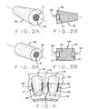
- the recessed region 102may be disposed at only one axial end of the rolling element, or both, and may extend either partially or completely through the axial length of the rolling element 100. For example, at the large end of tapered rolling elements as seen in Figures 2A and 2B , or at opposite axial ends of cylindrical rolling elements as seen in Figured 3A and 3B.
- a mechanical bearing assemblyin a second exemplary embodiment shown in Figure 4 , includes a bearing cage structure 150 for positioning a plurality of rolling elements 152, such as tapered rollers, for rolling movement between first and second raceways (not shown) in a spaced configuration.
- the bearing cage structure 150includes a plurality of bridge members 154 extending between each rolling element 152.
- a contained volume of additive gel 10is operatively disposed in a recessed region 156 on at least one bridge member 154 of the cage structure 150, to provide a controlled release of the contained additives from the gel 10 over time or as a function of temperature, through perforations or openings in the enclosure, in close operative proximity to the wear surfaces the rolling elements 152 and raceways.
- the specific configuration and shape of the bearing cage structure 150 and bridge members 154may be varied depending upon the shape and configuration of the rolling elements 152 of the bearing assembly, and accordingly, the specific shape and configuration of the recessed regions 156 in the bearing bridge members 154 may be modified accordingly.
- a mechanical bearing assemblyincludes a plurality of rolling elements supported for rolling movement between first and second raceways of first and second races.
- a contained volume of additive gel 10is operatively disposed on at least one of the races 160 in a single recessed region 162 as shown in the angled race 160a of Figures 5A and 5B , or in a pair of recessed regions 162A and 162B as shown in the cylindrical race 160b of Figures 6A and 6B , adjacent at least one circumferential edge or rib 164 of the associated raceway 166.
- the contained volume of additive gel 10provides a controlled release of the contained additives over time or as a function of temperature, through perforations or openings in an enclosing material, in close operative proximity to the wear surfaces the rolling element and raceways 166.
- the recessed region 162may extend about the entire circumference of the race 160, forming a channel or annular recess, or may be defined by one or more discrete arcuate recessed segments.
- a mechanical gear system or assemblyincluding at least one toothed gear 300 for meshed engagement with a toothed or threaded structure (not shown) is adapted to receive and retain one or more volumes of the lubricant additive gel 10.
- the contained volumes of additive gel 10are operative disposed in recessed regions 302 associated with at least one of the gear teeth 304 to provide a controlled release of the contained additives over time or as a function of temperature, through perforations or openings in an enclosing material, in close operative proximity to the wear surfaces the adjacent gear teeth 304.
- the recessed regions 302 for receiving the contained volumes of additive gel 10may be located at the root (dedendum) 304R of the gear teeth 304, at the tip (addendum) 304T of the gear teeth 304, or at both locations.
- the specific placement and number of recessed regions 302 on a gear 300may be varied depending upon the size, configuration, and application for which the gear 300 intended to be used.
- a lubricant additive gel 10in a mechanical system such as a friction reducing system (i.e., bearing assembly) or power transmission system (i.e. gear assembly) as described herein is not limited to the specific exemplary embodiments set forth above. Any system in which a lubricant is utilized to reduce wear or friction between moving parts, and which risks damage or excessive wear upon the break-down of the lubricant, may benefit from the incorporation of a lubricant additive gel 10 disposed and contained in proximity to wear critical surfaces, such as within a bearing assembly of a packaged bearing unit.
Landscapes
- Engineering & Computer Science (AREA)
- General Engineering & Computer Science (AREA)
- Mechanical Engineering (AREA)
- Rolling Contact Bearings (AREA)
Description
- The present application is related to, and claims priority from,
U.S. Provisional Patent Application Serial No. 61/242,017 filed on September 14, 2009 - The present application is related to the protection of bearing components and gear assemblies from wear or oil oxidation, and in particular to the protection of such components and assemblies by containing a volume of controlled-release additive gel in operative proximity to the bearing components and gear assemblies.
- Lubricant additive chemical technology is well known to improve the wear resistance of metallic surfaces. Similarly, anti-oxidant additives have been engineered to prolong the life of hydrocarbon lubricants by hindering oxidation reactions. The traditional approach for using these lubricant additives is to supply the additives with the initial lubrication as a full formulations. However, with this traditional approach, once the additives are depleted from the lubricant, they are not replenished until fresh lubricant is supplied. Furthermore, the additives are dispersed within the flow of lubricant through the entire lubrication system, and may not be present at sufficient quantity where needed, or may be depleted by reactions at noncritical or non-wear surfaces within the system.
- As described in
WO 2007/148047 various mechanical systems which operate in conjunction with lubricant filters have been designed in an attempt to provide a uniform dispersion of additives into a volume of lubricant over time. These systems often include capsules, perforated sheets, baffles, or specially designed injectors for achieving a slow release of additive into a flow of lubricant passing through the lubrication filter. In alternate designs, a slow-release of lubricant additives within lubrication filters is achieved by incorporating additives into oil-soluble solid polymers such as thermoplastics, inert carriers, or oil-soluble gels. While these systems provide for a slow release of additives into the flow of lubricant passing through the lubrication filter, they ultimately fail to ensure that sufficient quantity of the additives are provided a critical locations or wear surfaces, due to the uniform dispersion of the additives within the flow of lubricant. US 4492415 describes an alternative lubrication system for a rolling bearing which is made of a self-lubricating matrix forming the rolling bearing cage and is able to release lubricant in responses to sliding friction.- Accordingly, it would be advantageous to provide lubricated surfaces such as those found in bearing components and gear assemblies, with a source of beneficial lubricant additives which can be released in a controlled manner in proximity to wear critical surfaces as required to minimize wear or oil oxidation during operation.
- Briefly stated, the present disclosure provides a structure for containing a volume of lubricant additive gel which is disposed within a mechanical system, in close proximity to wear critical surfaces, and which is configured to provide a release of the contained additives over time or as a function of temperature in a site-specific manner to minimize wear or reduce oil oxidation due to harsh operating conditions. The structure defines a cage or capsule with screen or mesh sides having multiple perforations or openings through which a flow of lubricant may circulate. With in the contained volume of the structure, additives are disposed in a gel matrix, and are release over time or as a function of temperature, through the perforations or openings, in close operative proximity to wear critical surfaces of the mechanical system.
- In one embodiment the mechanical system is a bearing assembly, including at least one rolling element supported for rolling movement between first and second raceways. A contained volume of additive gel is operatively disposed in a recessed region adjacent at least one axial end of the rolling element, to provide a controlled release of the contained additives over time or as a function of temperature, through the perforations or openings, in close operative proximity to the wear surfaces the rolling element and raceways.
- In an alternate embodiment the mechanical system is a bearing assembly, including a plurality of rolling elements supported for rolling movement between first and second raceways in a spaced configuration by a bearing cage structure having bridge members extending between each rolling element. A contained volume of additive gel is operatively disposed in a recessed region on at least one bridge element of the bearing cage adjacent to a surface of the rolling elements, to provide a controlled release of the contained additives over time or as a function of temperature, through the perforations or openings, in close operative proximity to the wear surfaces the rolling element and raceways.
- In a further embodiment the mechanical system is a bearing assembly, including a plurality of rolling elements supported for rolling movement between first and second raceways of first and second races. A contained volume of additive gel is operatively disposed on at least one of the races in a recessed region adjacent at least one circumferential edge of the associated raceway and adjacent to a surface of the rolling elements, to provide a controlled release of the contained additives over time or as a function of temperature, through the perforations or openings, in close operative proximity to the wear surfaces the rolling element and raceways.
- In yet another embodiment, the mechanical system is a gear assembly including at least one toothed gear for meshed engagement with a toothed or threaded structure. A contained volume of additive gel is operative disposed in a recessed region associated with at least one of the gear teeth to provide a controlled release of the contained additives over time or as a function of temperature, through the perforations or openings, in close operative proximity to the wear surfaces the tooth. The recessed region for receiving the contained volume of additive gel may be located either at the root (dedendum) of the gear tooth, or at the tip (addendum) of the gear tooth.
- The foregoing features, and advantages set forth in the present disclosure as well as presently preferred embodiments will become more apparent from the reading of the following description in connection with the accompanying drawings.
- In the accompanying drawings which form part of the specification:
Figure 1 is a sectional illustration of a prior art railroad bearing which may be adapted to utilized the contained volumes of additive gels of the present disclosureFigure 2A is a perspective illustration of a tapered rolling element having a recessed axial region for receiving a contained volume of additive gel;Figure 2B is a cross-sectional view of the tapered rolling element ofFig. 2A ;Figure 3A is a perspective illustration of a cylindrical rolling element having recessed axial regions for receiving contained volumes of additive gel;Figure 3B is a cross-sectional view of the cylindrical rolling element ofFig. 3A ;Figure 4 is a perspective illustration of the placement of contained volumes of additive gel on a bearing cage bridge component;Figure 5A is a sectional view of a bearing race for tapered rolling elements, illustrating placement of a contained volume of additive gel at the raceway-flange undercut location;Figure 5B is a perspective view of a portion of the raceway ofFig. 5A ;Figure 6A is a sectional view of a bearing race for cylindrical rolling elements, illustrating placement of a contained volume of additive gel at the raceway-flange undercut locations;Figure 6B is a perspective view of a portion of the raceway ofFig. 6A ;Figure 7 is a sectional view of a toothed gear, illustrating the placement of contained volumes of additive gels at the gear tooth roots;Figure 8A is a perspective illustration of an exemplary mesh tablet containing an additive gel within a defined volume of space;Figure 8B is a cross section view of the mesh tablet ofFig. 8A , illustrating the additive containing gel disposed within the enclosing mesh structure;Figure 9 is a perspective illustration of an exemplary mesh block containing an additive gel within a defined volume of space; andFigure 10 is a perspective illustration of an exemplary mesh ring containing an additive gel within a defined volume of space.- Corresponding reference numerals indicate corresponding parts throughout the several figures of the drawings. It is to be understood that the drawings are for illustrating the concepts set forth in the present disclosure and are not to scale.
- Before any embodiments of the invention are explained in detail, it is to be understood that the invention is not limited in its application to the details of construction and the arrangement of components set forth in the following description or illustrated in the drawings.
- The following detailed description illustrates the invention by way of example and not by way of limitation. The description enables one skilled in the art to make and use the present disclosure, and describes several embodiments, adaptations, variations, alternatives, and uses of the present disclosure, including what is presently believed to be the best mode of carrying out the present disclosure.
- Lubricant additives retained or suspended in a gel form are not easily retained in their natural stage by specific placement within mechanical systems, such as friction management or power transmission systems shown in
Figure 1 , as the mechanical properties of the gels are not suitable for adhesion onto a solid surface. Turning to the figures, and toFigure 2A through Figure 7 in particular, various components of mechanical systems such as rolling element bearings or gear assemblies are shown to be adapted with recessed regions in proximity to wear critical surfaces, to receive and to physically retainlubricant additive gels 10, either by enclosing thelubricant additive gel 10 within the recessed region by a screen or mesh, or by seating anadditive gel 10 containingstructure 200 within the recessed region. Additives disposed in the gel matrix are released into a passing flow of lubricant in a controlled manner, such as by gradual release over time or as a function of temperature from the recessed region, through the perforations or openings in the enclosure or containingstructure 200, directly into close operative proximity to wear critical surfaces of the mechanical system. - Exemplary lubricant additive gels include wear resistant additive gels (extreme pressure "EP" or anti-wear "AW' gels) which can be designed to release beneficial molecules when the environment temperature reaches a designated threshold. During the onset of wear in the mechanical system, the operating temperature in the vicinity of the gel will begin to rise, prompting the release of the additives into the immediate environment when needed to slow the onset of any frictional damage and to extend the useful protection life of the lubricants. Additional lubricant additive gels include antioxidant components that may be designed to be released over time to prolong the life of circulating lubricant.
Structures 200 of the present disclosure for containing a volume of lubricant additive gel for controlled release into a flow of lubricant are shown generally intablet form 200A as seen inFigure 8 , box or brick form 200B as seen inFigure 9 , or annular /ring form 200C as best seen inFigure 10 . Thevarious structures 200 are intended to be disposed within correspondingly sized recesses in a mechanical system, such as a rolling element bearing or gear assembly, in close proximity to wear critical surfaces, and are configured to facilitate a release of the contained lubricant additives into a flow of lubricant over time or as a function of temperature in a site-specific manner to minimize wear or reduce oil oxidation due to harsh operating conditions. Preferably, thestructures 200 each define a cage or capsule, with screened, meshed, or slottedsurfaces 202, having multiple perforations or openings through which a flow of lubricant may circulate to reach the gel additive, and through which the contained lubricant additives may be released as the gel dissolves.- Returning to
Figures 2A through 3B , in one exemplary embodiment of the present disclosure, a rollingelement 100 for use with a mechanical bearing assembly to support rolling movement between first and second raceways (not shown), is adapted to retain a lubricant additive gel in proximity to the rolling element surfaces and supporting raceway surfaces. A contained volume ofadditive gel 10 is operatively disposed in a recessedregion 102 adjacent at least one axial end of the rollingelement 100, to provide a controlled release of the contained additives from thegel 10 over time or as a function of temperature, through the perorations or openings in a cover, screen or retainingstructure 104, in close operative proximity to the wear surfaces the rolling element and raceways. The recessedregion 102 may be disposed at only one axial end of the rolling element, or both, and may extend either partially or completely through the axial length of the rollingelement 100. For example, at the large end of tapered rolling elements as seen inFigures 2A and 2B , or at opposite axial ends of cylindrical rolling elements as seen in Figured 3A and 3B. - In a second exemplary embodiment shown in
Figure 4 , a mechanical bearing assembly, includes a bearingcage structure 150 for positioning a plurality of rollingelements 152, such as tapered rollers, for rolling movement between first and second raceways (not shown) in a spaced configuration. The bearingcage structure 150 includes a plurality ofbridge members 154 extending between each rollingelement 152. A contained volume ofadditive gel 10 is operatively disposed in a recessedregion 156 on at least onebridge member 154 of thecage structure 150, to provide a controlled release of the contained additives from thegel 10 over time or as a function of temperature, through perforations or openings in the enclosure, in close operative proximity to the wear surfaces the rollingelements 152 and raceways. The specific configuration and shape of the bearingcage structure 150 andbridge members 154 may be varied depending upon the shape and configuration of the rollingelements 152 of the bearing assembly, and accordingly, the specific shape and configuration of the recessedregions 156 in the bearingbridge members 154 may be modified accordingly. - In a third exemplary embodiment, a mechanical bearing assembly includes a plurality of rolling elements supported for rolling movement between first and second raceways of first and second races. As shown in
Figures 5A through 6B , a contained volume ofadditive gel 10 is operatively disposed on at least one of the races 160 in a single recessedregion 162 as shown in the angled race 160a ofFigures 5A and 5B , or in a pair of recessedregions Figures 6A and 6B , adjacent at least one circumferential edge orrib 164 of the associatedraceway 166. The contained volume ofadditive gel 10 provides a controlled release of the contained additives over time or as a function of temperature, through perforations or openings in an enclosing material, in close operative proximity to the wear surfaces the rolling element andraceways 166. The recessedregion 162 may extend about the entire circumference of the race 160, forming a channel or annular recess, or may be defined by one or more discrete arcuate recessed segments. - In yet another exemplary embodiment, shown in
Figure 7 , a mechanical gear system or assembly including at least onetoothed gear 300 for meshed engagement with a toothed or threaded structure (not shown) is adapted to receive and retain one or more volumes of thelubricant additive gel 10. The contained volumes ofadditive gel 10 are operative disposed in recessedregions 302 associated with at least one of thegear teeth 304 to provide a controlled release of the contained additives over time or as a function of temperature, through perforations or openings in an enclosing material, in close operative proximity to the wear surfaces theadjacent gear teeth 304. The recessedregions 302 for receiving the contained volumes ofadditive gel 10 may be located at the root (dedendum) 304R of thegear teeth 304, at the tip (addendum) 304T of thegear teeth 304, or at both locations. The specific placement and number of recessedregions 302 on agear 300 may be varied depending upon the size, configuration, and application for which thegear 300 intended to be used. - Those of ordinary skill in the art will recognize that use of a
lubricant additive gel 10 in a mechanical system such as a friction reducing system (i.e., bearing assembly) or power transmission system (i.e. gear assembly) as described herein is not limited to the specific exemplary embodiments set forth above. Any system in which a lubricant is utilized to reduce wear or friction between moving parts, and which risks damage or excessive wear upon the break-down of the lubricant, may benefit from the incorporation of alubricant additive gel 10 disposed and contained in proximity to wear critical surfaces, such as within a bearing assembly of a packaged bearing unit. By incorporating gel-receiving recesses such as 102, 162, and 302 in close proximity to the wear critical surfaces, and by providing anadditive gel 10 having a controlled release mechanism, such as one which is responsive to an increase in temperature to release additional additives from thegel 10, protection for the wear critical surfaces can be provided with improved efficiency. - As various changes could be made in the above constructions without departing from the scope of the disclosure, it is intended that all matter contained in the above description or shown in the accompanying drawings shall be interpreted as illustrative and not in a limiting sense.
Claims (15)
- A method for providing a controlled release wear protection to a mechanical component, comprising:providing the mechanical component with a recessed region (102, 162, 302) for receiving a lubricant additive gel (10) in operative proximity to a wear critical surface of the mechanical component;disposing the lubricant additive gel (10) containing lubricant additives within said recessed region; andsecuring said lubricant additive gel (10) within said recessed region on said mechanical component for controlled release of said lubricant additives into a flow of passing lubricant by dissolution of said gel in close proximity to said wear critical surface.
- The method of Claim 1 wherein said dissolution of said lubricant additive gel and said controlled release of said lubricant additives into said flow of lubricant is responsive to an increase in environmental temperature associated with increased wear on said proximate wear critical surface.
- The method of Claim 1 wherein said dissolution of said lubricant additive gel and said controlled release of said lubricant additive into said flow of lubricant is a time based release.
- The method of Claim 1 wherein said step of securing said additive gel (10) within said recessed region (102, 162, 302) includes containing said additive gel within a contained structure (200) adapted for fitment within said recessed region (102, 162, 302), said contained structure (200) defining a volume for receiving said additive gel (10) and having a plurality of openings between an external environment and said defined volume to facilitate said controlled release of said lubricant additives from said additive gel to said flow of lubricant.
- A mechanical system having at least one mechanical component with a wear critical surface lubricated by a flow of lubricant, comprising:a recessed region (102, 162, 302) on a surface (100, 154, 160, 304) within said mechanical system in proximity to said wear critical surface of the mechanical component and said flow of lubricant;a lubricant additive dissolvable gel (10) disposed within said recessed region (102, 162, 302);a retention structure (104, 202) configured to retain said lubricant additive dissolvable gel within said recessed region; andwherein said lubricant additive dissolvable gel contains lubricant additives adapted for controlled release through said retention structure into a flow of passing lubricant in proximity to said wear critical surface.
- The mechanical system of Claim 5 wherein said controlled release of said lubricant additives into said flow of passing lubricant is responsive to an increase in environmental temperature associated with increased wear on said wear critical surface.
- The mechanical system of Claim 5 wherein said controlled release of said lubricant additive into said flow of lubricant is a time-based release.
- The mechanical system of Claim 5 wherein said mechanical system is a bearing assembly, wherein said mechanical component is a rolling element (100), and wherein said surface with said recessed region is an axial end of said rolling element.
- The mechanical system of Claim 5 wherein said mechanical system is a bearing assembly, wherein said mechanical component is a rolling element (100) and wherein said surface with said recessed region (162A, 162B) is a race (160A, 160B) having a raceway (166) for supporting said rolling element.
- The mechanical system of Claim 9 wherein said recessed region is disposed adjacent a circumferential edge (164) of said raceway.
- The mechanical system of Claim 5 wherein said mechanical system is a bearing assembly, wherein said mechanical component is one of a plurality of rolling elements (152) secured in position about a raceway of a race by a bearing cage structure (150), and wherein said surface with said recessed region (156) is disposed on a bridge member (154) of said bearing cage structure separating adjacent rolling elements.
- The mechanical system of Claim 5 wherein said mechanical system is a gear assembly, wherein said mechanical component is a gear (300) having a plurality of gear teeth (304), each having a wear critical surface, and wherein said surface with said recessed region (302) is disposed on said gear in proximity to at least one of said gear teeth.
- The mechanical system of Claim 12 wherein said surface with said recessed region is disposed either at a gear root (304R) or at a gear tip (304T).
- The mechanical system of Claim 5 wherein said lubricant additive dissolvable gel (10) contains an antioxidant component adapted for release into said flow of lubricant over time.
- The mechanical system of Claim 5 wherein said lubricant additive dissolvable gel (10) contains a wear resistant component adapted for release into said flow of lubricant in response to an increase in temperature.
Applications Claiming Priority (2)
| Application Number | Priority Date | Filing Date | Title |
|---|---|---|---|
| US24201709P | 2009-09-14 | 2009-09-14 | |
| PCT/US2010/048608WO2011032081A1 (en) | 2009-09-14 | 2010-09-13 | Apparatus and method for controlled release of lubricant additives in bearing and gear assemblies |
Publications (2)
| Publication Number | Publication Date |
|---|---|
| EP2478238A1 EP2478238A1 (en) | 2012-07-25 |
| EP2478238B1true EP2478238B1 (en) | 2013-08-28 |
Family
ID=43016910
Family Applications (1)
| Application Number | Title | Priority Date | Filing Date |
|---|---|---|---|
| EP10755284.6AActiveEP2478238B1 (en) | 2009-09-14 | 2010-09-13 | Apparatus and method for controlled release of lubricant additives in bearing and gear assemblies |
Country Status (4)
| Country | Link |
|---|---|
| US (1) | US8727627B2 (en) |
| EP (1) | EP2478238B1 (en) |
| KR (1) | KR101544255B1 (en) |
| WO (1) | WO2011032081A1 (en) |
Families Citing this family (11)
| Publication number | Priority date | Publication date | Assignee | Title |
|---|---|---|---|---|
| DE102013218286A1 (en)* | 2013-09-12 | 2015-03-12 | Schaeffler Technologies AG & Co. KG | Cage for a rolling bearing and associated rolling bearing |
| DE102015203198A1 (en)* | 2014-03-06 | 2015-09-10 | Schaeffler Technologies AG & Co. KG | Method for supplying a bearing unit with lubricant |
| JP2016173152A (en)* | 2015-03-17 | 2016-09-29 | Ntn株式会社 | Cage and rolling bearing |
| DE102019201560A1 (en) | 2019-02-07 | 2020-08-13 | Aktiebolaget Skf | Bearing cage segment with abutting edge for welding |
| CN110410418B (en)* | 2019-07-18 | 2021-07-13 | 风下电机(山东)有限公司 | An oil-impregnated bearing capable of independently replenishing lubricating oil and a replenishing method |
| WO2022022929A1 (en)* | 2020-07-29 | 2022-02-03 | Sew-Eurodrive Gmbh & Co. Kg | Method for manufacturing a transmission with lubricant, and transmission system |
| DE102021206282A1 (en) | 2021-06-18 | 2022-12-22 | Aktiebolaget Skf | Cage segment for a roller bearing cage |
| DE102021206285A1 (en) | 2021-06-18 | 2022-12-22 | Aktiebolaget Skf | Cage segment for a roller bearing cage |
| DE102021206284A1 (en) | 2021-06-18 | 2022-12-22 | Aktiebolaget Skf | Cage segment for a roller bearing cage |
| DE102022200327A1 (en)* | 2022-01-13 | 2023-07-13 | Aktiebolaget Skf | bearing cage |
| DE102022200326A1 (en) | 2022-01-13 | 2023-07-13 | Aktiebolaget Skf | Cage segment for a segment cage |
Family Cites Families (12)
| Publication number | Priority date | Publication date | Assignee | Title |
|---|---|---|---|---|
| US3749247A (en)* | 1970-09-21 | 1973-07-31 | Phillips Petroleum Co | Addition of oxidation inhibitor to lubricating oil |
| US4492415A (en) | 1982-03-03 | 1985-01-08 | Skf Industries, Inc. | Unitary full complement bearing components containing rolling elements in a self-supporting lubricating matrix |
| JP2003156056A (en)* | 2001-11-20 | 2003-05-30 | Nsk Ltd | Roller bearing |
| US7384896B2 (en)* | 2002-07-16 | 2008-06-10 | The Lubrizol Corporation | Controlled release of additive gel(s) for functional fluids |
| DE10258842B4 (en)* | 2002-12-17 | 2011-03-24 | Zf Lenksysteme Gmbh | Rack and pinion steering gear |
| US7534747B2 (en)* | 2003-06-25 | 2009-05-19 | The Lubrizol Corporation | Gels that reduce soot and/or emissions from engines |
| EP1803792A4 (en)* | 2004-10-20 | 2010-07-28 | Porite Corp | THERMOREVERSIBLE GEL LUBRICATING COMPOSITION, METHOD FOR MANUFACTURING SAME, AND BEARING LUBRICANT AND BEARING SYSTEM USING SAME |
| US20070049505A1 (en)* | 2005-08-24 | 2007-03-01 | Baker Mark R | Controlled release of additive gel(s) for functional fluids |
| JP4715554B2 (en)* | 2006-03-01 | 2011-07-06 | パナソニック株式会社 | Bearing and motor using the bearing |
| EP1880751A1 (en)* | 2006-06-21 | 2008-01-23 | Castrol Limited | Apparatus and method for adding additives to engine lubricant |
| JP2008039052A (en)* | 2006-08-07 | 2008-02-21 | Matsushita Electric Ind Co Ltd | Bearing and motor using the bearing |
| US7833955B2 (en)* | 2006-11-08 | 2010-11-16 | The Lubrizol Corporation | Viscosity modifiers in controlled release lubricant additive gels |
- 2010
- 2010-09-13EPEP10755284.6Apatent/EP2478238B1/enactiveActive
- 2010-09-13KRKR1020127009383Apatent/KR101544255B1/enactiveActive
- 2010-09-13USUS13/395,806patent/US8727627B2/enactiveActive
- 2010-09-13WOPCT/US2010/048608patent/WO2011032081A1/enactiveApplication Filing
Also Published As
| Publication number | Publication date |
|---|---|
| WO2011032081A1 (en) | 2011-03-17 |
| KR20120063521A (en) | 2012-06-15 |
| EP2478238A1 (en) | 2012-07-25 |
| US8727627B2 (en) | 2014-05-20 |
| KR101544255B1 (en) | 2015-08-12 |
| US20120170883A1 (en) | 2012-07-05 |
Similar Documents
| Publication | Publication Date | Title |
|---|---|---|
| EP2478238B1 (en) | Apparatus and method for controlled release of lubricant additives in bearing and gear assemblies | |
| US9267543B2 (en) | Cage unit and tapered roller bearing equipped with cage unit | |
| EP2770220A1 (en) | Roller bearing | |
| US9726224B2 (en) | Tapered roller bearing | |
| JP2005530968A (en) | Epicyclic drive with integral planetary gear assembly | |
| CN1987147A (en) | Solid lubrication oil-free chain | |
| CN101235890A (en) | Shaft antiseizing type sprocket | |
| CN102583010A (en) | Conveyor chain | |
| JP2007232186A (en) | Cylindrical roller bearing for wind power generator | |
| JP2007263357A (en) | Planetary gearing unit and speed increasing gear for aerogenerator | |
| JP4692385B2 (en) | Rolling bearing device | |
| EP2390520A2 (en) | Roller bearing | |
| JP2007270628A (en) | Roller bearing for fuel pump | |
| AU2018204078B2 (en) | A grease retaining and oil metering device for a rolling bearing unit | |
| JP2013122257A (en) | Rolling bearing | |
| JP5062045B2 (en) | Thrust roller bearing | |
| CN203463496U (en) | Self-lubricating bearing | |
| EP2781777A1 (en) | Rolling bearing unit | |
| JP2010180932A (en) | Sealing structure for one-way clutch | |
| JP5889596B2 (en) | Roller bearing | |
| WO2014085584A1 (en) | Crankshaft thrust bearing and engine containing same | |
| CN107002759A (en) | grease distributor device for rolling bearing | |
| CN202768633U (en) | Cobwebbed shaft bushing | |
| JP5084575B2 (en) | Sealing device and rolling bearing device | |
| JP2007270852A (en) | Roller bearing for hydraulic pressure pump |
Legal Events
| Date | Code | Title | Description |
|---|---|---|---|
| PUAI | Public reference made under article 153(3) epc to a published international application that has entered the european phase | Free format text:ORIGINAL CODE: 0009012 | |
| 17P | Request for examination filed | Effective date:20120402 | |
| AK | Designated contracting states | Kind code of ref document:A1 Designated state(s):AL AT BE BG CH CY CZ DE DK EE ES FI FR GB GR HR HU IE IS IT LI LT LU LV MC MK MT NL NO PL PT RO SE SI SK SM TR | |
| DAX | Request for extension of the european patent (deleted) | ||
| GRAP | Despatch of communication of intention to grant a patent | Free format text:ORIGINAL CODE: EPIDOSNIGR1 | |
| INTG | Intention to grant announced | Effective date:20130404 | |
| GRAS | Grant fee paid | Free format text:ORIGINAL CODE: EPIDOSNIGR3 | |
| GRAA | (expected) grant | Free format text:ORIGINAL CODE: 0009210 | |
| AK | Designated contracting states | Kind code of ref document:B1 Designated state(s):AL AT BE BG CH CY CZ DE DK EE ES FI FR GB GR HR HU IE IS IT LI LT LU LV MC MK MT NL NO PL PT RO SE SI SK SM TR | |
| REG | Reference to a national code | Ref country code:GB Ref legal event code:FG4D | |
| REG | Reference to a national code | Ref country code:CH Ref legal event code:EP | |
| REG | Reference to a national code | Ref country code:AT Ref legal event code:REF Ref document number:629532 Country of ref document:AT Kind code of ref document:T Effective date:20130915 | |
| REG | Reference to a national code | Ref country code:IE Ref legal event code:FG4D | |
| REG | Reference to a national code | Ref country code:DE Ref legal event code:R096 Ref document number:602010009828 Country of ref document:DE Effective date:20131024 | |
| REG | Reference to a national code | Ref country code:AT Ref legal event code:MK05 Ref document number:629532 Country of ref document:AT Kind code of ref document:T Effective date:20130828 | |
| REG | Reference to a national code | Ref country code:LT Ref legal event code:MG4D | |
| REG | Reference to a national code | Ref country code:NL Ref legal event code:VDEP Effective date:20130828 | |
| PG25 | Lapsed in a contracting state [announced via postgrant information from national office to epo] | Ref country code:NO Free format text:LAPSE BECAUSE OF FAILURE TO SUBMIT A TRANSLATION OF THE DESCRIPTION OR TO PAY THE FEE WITHIN THE PRESCRIBED TIME-LIMIT Effective date:20131128 Ref country code:AT Free format text:LAPSE BECAUSE OF FAILURE TO SUBMIT A TRANSLATION OF THE DESCRIPTION OR TO PAY THE FEE WITHIN THE PRESCRIBED TIME-LIMIT Effective date:20130828 Ref country code:HR Free format text:LAPSE BECAUSE OF FAILURE TO SUBMIT A TRANSLATION OF THE DESCRIPTION OR TO PAY THE FEE WITHIN THE PRESCRIBED TIME-LIMIT Effective date:20130828 Ref country code:CY Free format text:LAPSE BECAUSE OF FAILURE TO SUBMIT A TRANSLATION OF THE DESCRIPTION OR TO PAY THE FEE WITHIN THE PRESCRIBED TIME-LIMIT Effective date:20130904 Ref country code:PT Free format text:LAPSE BECAUSE OF FAILURE TO SUBMIT A TRANSLATION OF THE DESCRIPTION OR TO PAY THE FEE WITHIN THE PRESCRIBED TIME-LIMIT Effective date:20131230 Ref country code:LT Free format text:LAPSE BECAUSE OF FAILURE TO SUBMIT A TRANSLATION OF THE DESCRIPTION OR TO PAY THE FEE WITHIN THE PRESCRIBED TIME-LIMIT Effective date:20130828 Ref country code:IS Free format text:LAPSE BECAUSE OF FAILURE TO SUBMIT A TRANSLATION OF THE DESCRIPTION OR TO PAY THE FEE WITHIN THE PRESCRIBED TIME-LIMIT Effective date:20131228 Ref country code:SE Free format text:LAPSE BECAUSE OF FAILURE TO SUBMIT A TRANSLATION OF THE DESCRIPTION OR TO PAY THE FEE WITHIN THE PRESCRIBED TIME-LIMIT Effective date:20130828 | |
| REG | Reference to a national code | Ref country code:NL Ref legal event code:VDEP Effective date:20130828 | |
| PG25 | Lapsed in a contracting state [announced via postgrant information from national office to epo] | Ref country code:SI Free format text:LAPSE BECAUSE OF FAILURE TO SUBMIT A TRANSLATION OF THE DESCRIPTION OR TO PAY THE FEE WITHIN THE PRESCRIBED TIME-LIMIT Effective date:20130828 Ref country code:GR Free format text:LAPSE BECAUSE OF FAILURE TO SUBMIT A TRANSLATION OF THE DESCRIPTION OR TO PAY THE FEE WITHIN THE PRESCRIBED TIME-LIMIT Effective date:20131129 Ref country code:LV Free format text:LAPSE BECAUSE OF FAILURE TO SUBMIT A TRANSLATION OF THE DESCRIPTION OR TO PAY THE FEE WITHIN THE PRESCRIBED TIME-LIMIT Effective date:20130828 Ref country code:PL Free format text:LAPSE BECAUSE OF FAILURE TO SUBMIT A TRANSLATION OF THE DESCRIPTION OR TO PAY THE FEE WITHIN THE PRESCRIBED TIME-LIMIT Effective date:20130828 Ref country code:BE Free format text:LAPSE BECAUSE OF FAILURE TO SUBMIT A TRANSLATION OF THE DESCRIPTION OR TO PAY THE FEE WITHIN THE PRESCRIBED TIME-LIMIT Effective date:20130828 Ref country code:FI Free format text:LAPSE BECAUSE OF FAILURE TO SUBMIT A TRANSLATION OF THE DESCRIPTION OR TO PAY THE FEE WITHIN THE PRESCRIBED TIME-LIMIT Effective date:20130828 | |
| PG25 | Lapsed in a contracting state [announced via postgrant information from national office to epo] | Ref country code:CY Free format text:LAPSE BECAUSE OF FAILURE TO SUBMIT A TRANSLATION OF THE DESCRIPTION OR TO PAY THE FEE WITHIN THE PRESCRIBED TIME-LIMIT Effective date:20130828 | |
| PG25 | Lapsed in a contracting state [announced via postgrant information from national office to epo] | Ref country code:NL Free format text:LAPSE BECAUSE OF FAILURE TO SUBMIT A TRANSLATION OF THE DESCRIPTION OR TO PAY THE FEE WITHIN THE PRESCRIBED TIME-LIMIT Effective date:20130828 Ref country code:CZ Free format text:LAPSE BECAUSE OF FAILURE TO SUBMIT A TRANSLATION OF THE DESCRIPTION OR TO PAY THE FEE WITHIN THE PRESCRIBED TIME-LIMIT Effective date:20130828 Ref country code:DK Free format text:LAPSE BECAUSE OF FAILURE TO SUBMIT A TRANSLATION OF THE DESCRIPTION OR TO PAY THE FEE WITHIN THE PRESCRIBED TIME-LIMIT Effective date:20130828 Ref country code:SK Free format text:LAPSE BECAUSE OF FAILURE TO SUBMIT A TRANSLATION OF THE DESCRIPTION OR TO PAY THE FEE WITHIN THE PRESCRIBED TIME-LIMIT Effective date:20130828 Ref country code:RO Free format text:LAPSE BECAUSE OF FAILURE TO SUBMIT A TRANSLATION OF THE DESCRIPTION OR TO PAY THE FEE WITHIN THE PRESCRIBED TIME-LIMIT Effective date:20130828 Ref country code:EE Free format text:LAPSE BECAUSE OF FAILURE TO SUBMIT A TRANSLATION OF THE DESCRIPTION OR TO PAY THE FEE WITHIN THE PRESCRIBED TIME-LIMIT Effective date:20130828 | |
| PG25 | Lapsed in a contracting state [announced via postgrant information from national office to epo] | Ref country code:ES Free format text:LAPSE BECAUSE OF FAILURE TO SUBMIT A TRANSLATION OF THE DESCRIPTION OR TO PAY THE FEE WITHIN THE PRESCRIBED TIME-LIMIT Effective date:20130828 Ref country code:MC Free format text:LAPSE BECAUSE OF FAILURE TO SUBMIT A TRANSLATION OF THE DESCRIPTION OR TO PAY THE FEE WITHIN THE PRESCRIBED TIME-LIMIT Effective date:20130828 Ref country code:IT Free format text:LAPSE BECAUSE OF FAILURE TO SUBMIT A TRANSLATION OF THE DESCRIPTION OR TO PAY THE FEE WITHIN THE PRESCRIBED TIME-LIMIT Effective date:20130828 | |
| REG | Reference to a national code | Ref country code:DE Ref legal event code:R097 Ref document number:602010009828 Country of ref document:DE | |
| REG | Reference to a national code | Ref country code:IE Ref legal event code:MM4A | |
| PLBE | No opposition filed within time limit | Free format text:ORIGINAL CODE: 0009261 | |
| STAA | Information on the status of an ep patent application or granted ep patent | Free format text:STATUS: NO OPPOSITION FILED WITHIN TIME LIMIT | |
| PG25 | Lapsed in a contracting state [announced via postgrant information from national office to epo] | Ref country code:IE Free format text:LAPSE BECAUSE OF NON-PAYMENT OF DUE FEES Effective date:20130913 | |
| 26N | No opposition filed | Effective date:20140530 | |
| REG | Reference to a national code | Ref country code:DE Ref legal event code:R097 Ref document number:602010009828 Country of ref document:DE Effective date:20140530 | |
| REG | Reference to a national code | Ref country code:CH Ref legal event code:PL | |
| PG25 | Lapsed in a contracting state [announced via postgrant information from national office to epo] | Ref country code:SM Free format text:LAPSE BECAUSE OF FAILURE TO SUBMIT A TRANSLATION OF THE DESCRIPTION OR TO PAY THE FEE WITHIN THE PRESCRIBED TIME-LIMIT Effective date:20130828 | |
| PG25 | Lapsed in a contracting state [announced via postgrant information from national office to epo] | Ref country code:MT Free format text:LAPSE BECAUSE OF FAILURE TO SUBMIT A TRANSLATION OF THE DESCRIPTION OR TO PAY THE FEE WITHIN THE PRESCRIBED TIME-LIMIT Effective date:20130828 Ref country code:TR Free format text:LAPSE BECAUSE OF FAILURE TO SUBMIT A TRANSLATION OF THE DESCRIPTION OR TO PAY THE FEE WITHIN THE PRESCRIBED TIME-LIMIT Effective date:20130828 | |
| PG25 | Lapsed in a contracting state [announced via postgrant information from national office to epo] | Ref country code:LU Free format text:LAPSE BECAUSE OF NON-PAYMENT OF DUE FEES Effective date:20130913 Ref country code:MK Free format text:LAPSE BECAUSE OF FAILURE TO SUBMIT A TRANSLATION OF THE DESCRIPTION OR TO PAY THE FEE WITHIN THE PRESCRIBED TIME-LIMIT Effective date:20130828 Ref country code:CH Free format text:LAPSE BECAUSE OF NON-PAYMENT OF DUE FEES Effective date:20140930 Ref country code:LI Free format text:LAPSE BECAUSE OF NON-PAYMENT OF DUE FEES Effective date:20140930 Ref country code:HU Free format text:LAPSE BECAUSE OF FAILURE TO SUBMIT A TRANSLATION OF THE DESCRIPTION OR TO PAY THE FEE WITHIN THE PRESCRIBED TIME-LIMIT; INVALID AB INITIO Effective date:20100913 Ref country code:BG Free format text:LAPSE BECAUSE OF FAILURE TO SUBMIT A TRANSLATION OF THE DESCRIPTION OR TO PAY THE FEE WITHIN THE PRESCRIBED TIME-LIMIT Effective date:20130828 | |
| REG | Reference to a national code | Ref country code:FR Ref legal event code:PLFP Year of fee payment:6 | |
| REG | Reference to a national code | Ref country code:FR Ref legal event code:PLFP Year of fee payment:7 | |
| REG | Reference to a national code | Ref country code:FR Ref legal event code:PLFP Year of fee payment:8 | |
| REG | Reference to a national code | Ref country code:FR Ref legal event code:PLFP Year of fee payment:9 | |
| PG25 | Lapsed in a contracting state [announced via postgrant information from national office to epo] | Ref country code:AL Free format text:LAPSE BECAUSE OF FAILURE TO SUBMIT A TRANSLATION OF THE DESCRIPTION OR TO PAY THE FEE WITHIN THE PRESCRIBED TIME-LIMIT Effective date:20130828 | |
| P01 | Opt-out of the competence of the unified patent court (upc) registered | Effective date:20230613 | |
| PGFP | Annual fee paid to national office [announced via postgrant information from national office to epo] | Ref country code:DE Payment date:20240918 Year of fee payment:15 | |
| PGFP | Annual fee paid to national office [announced via postgrant information from national office to epo] | Ref country code:GB Payment date:20240919 Year of fee payment:15 | |
| PGFP | Annual fee paid to national office [announced via postgrant information from national office to epo] | Ref country code:FR Payment date:20240925 Year of fee payment:15 |