EP2477555B1 - Device for cardiac valve repair - Google Patents
Device for cardiac valve repairDownload PDFInfo
- Publication number
- EP2477555B1 EP2477555B1EP10701087.8AEP10701087AEP2477555B1EP 2477555 B1EP2477555 B1EP 2477555B1EP 10701087 AEP10701087 AEP 10701087AEP 2477555 B1EP2477555 B1EP 2477555B1
- Authority
- EP
- European Patent Office
- Prior art keywords
- valve
- blocker
- heart
- bladder
- leaflets
- Prior art date
- Legal status (The legal status is an assumption and is not a legal conclusion. Google has not performed a legal analysis and makes no representation as to the accuracy of the status listed.)
- Active
Links
Images


Classifications
- A—HUMAN NECESSITIES
- A61—MEDICAL OR VETERINARY SCIENCE; HYGIENE
- A61B—DIAGNOSIS; SURGERY; IDENTIFICATION
- A61B17/00—Surgical instruments, devices or methods
- A61B17/00234—Surgical instruments, devices or methods for minimally invasive surgery
- A—HUMAN NECESSITIES
- A61—MEDICAL OR VETERINARY SCIENCE; HYGIENE
- A61F—FILTERS IMPLANTABLE INTO BLOOD VESSELS; PROSTHESES; DEVICES PROVIDING PATENCY TO, OR PREVENTING COLLAPSING OF, TUBULAR STRUCTURES OF THE BODY, e.g. STENTS; ORTHOPAEDIC, NURSING OR CONTRACEPTIVE DEVICES; FOMENTATION; TREATMENT OR PROTECTION OF EYES OR EARS; BANDAGES, DRESSINGS OR ABSORBENT PADS; FIRST-AID KITS
- A61F2/00—Filters implantable into blood vessels; Prostheses, i.e. artificial substitutes or replacements for parts of the body; Appliances for connecting them with the body; Devices providing patency to, or preventing collapsing of, tubular structures of the body, e.g. stents
- A61F2/02—Prostheses implantable into the body
- A61F2/24—Heart valves ; Vascular valves, e.g. venous valves; Heart implants, e.g. passive devices for improving the function of the native valve or the heart muscle; Transmyocardial revascularisation [TMR] devices; Valves implantable in the body
- A61F2/2427—Devices for manipulating or deploying heart valves during implantation
- A—HUMAN NECESSITIES
- A61—MEDICAL OR VETERINARY SCIENCE; HYGIENE
- A61B—DIAGNOSIS; SURGERY; IDENTIFICATION
- A61B17/00—Surgical instruments, devices or methods
- A61B17/00491—Surgical glue applicators
- A—HUMAN NECESSITIES
- A61—MEDICAL OR VETERINARY SCIENCE; HYGIENE
- A61B—DIAGNOSIS; SURGERY; IDENTIFICATION
- A61B17/00—Surgical instruments, devices or methods
- A61B17/04—Surgical instruments, devices or methods for suturing wounds; Holders or packages for needles or suture materials
- A61B17/0401—Suture anchors, buttons or pledgets, i.e. means for attaching sutures to bone, cartilage or soft tissue; Instruments for applying or removing suture anchors
- A—HUMAN NECESSITIES
- A61—MEDICAL OR VETERINARY SCIENCE; HYGIENE
- A61B—DIAGNOSIS; SURGERY; IDENTIFICATION
- A61B17/00—Surgical instruments, devices or methods
- A61B17/064—Surgical staples, i.e. penetrating the tissue
- A61B17/0644—Surgical staples, i.e. penetrating the tissue penetrating the tissue, deformable to closed position
- A—HUMAN NECESSITIES
- A61—MEDICAL OR VETERINARY SCIENCE; HYGIENE
- A61B—DIAGNOSIS; SURGERY; IDENTIFICATION
- A61B17/00—Surgical instruments, devices or methods
- A61B17/068—Surgical staplers, e.g. containing multiple staples or clamps
- A—HUMAN NECESSITIES
- A61—MEDICAL OR VETERINARY SCIENCE; HYGIENE
- A61B—DIAGNOSIS; SURGERY; IDENTIFICATION
- A61B17/00—Surgical instruments, devices or methods
- A61B17/08—Wound clamps or clips, i.e. not or only partly penetrating the tissue ; Devices for bringing together the edges of a wound
- A—HUMAN NECESSITIES
- A61—MEDICAL OR VETERINARY SCIENCE; HYGIENE
- A61B—DIAGNOSIS; SURGERY; IDENTIFICATION
- A61B17/00—Surgical instruments, devices or methods
- A61B17/08—Wound clamps or clips, i.e. not or only partly penetrating the tissue ; Devices for bringing together the edges of a wound
- A61B17/083—Clips, e.g. resilient
- A—HUMAN NECESSITIES
- A61—MEDICAL OR VETERINARY SCIENCE; HYGIENE
- A61F—FILTERS IMPLANTABLE INTO BLOOD VESSELS; PROSTHESES; DEVICES PROVIDING PATENCY TO, OR PREVENTING COLLAPSING OF, TUBULAR STRUCTURES OF THE BODY, e.g. STENTS; ORTHOPAEDIC, NURSING OR CONTRACEPTIVE DEVICES; FOMENTATION; TREATMENT OR PROTECTION OF EYES OR EARS; BANDAGES, DRESSINGS OR ABSORBENT PADS; FIRST-AID KITS
- A61F2/00—Filters implantable into blood vessels; Prostheses, i.e. artificial substitutes or replacements for parts of the body; Appliances for connecting them with the body; Devices providing patency to, or preventing collapsing of, tubular structures of the body, e.g. stents
- A61F2/02—Prostheses implantable into the body
- A61F2/24—Heart valves ; Vascular valves, e.g. venous valves; Heart implants, e.g. passive devices for improving the function of the native valve or the heart muscle; Transmyocardial revascularisation [TMR] devices; Valves implantable in the body
- A61F2/2412—Heart valves ; Vascular valves, e.g. venous valves; Heart implants, e.g. passive devices for improving the function of the native valve or the heart muscle; Transmyocardial revascularisation [TMR] devices; Valves implantable in the body with soft flexible valve members, e.g. tissue valves shaped like natural valves
- A—HUMAN NECESSITIES
- A61—MEDICAL OR VETERINARY SCIENCE; HYGIENE
- A61F—FILTERS IMPLANTABLE INTO BLOOD VESSELS; PROSTHESES; DEVICES PROVIDING PATENCY TO, OR PREVENTING COLLAPSING OF, TUBULAR STRUCTURES OF THE BODY, e.g. STENTS; ORTHOPAEDIC, NURSING OR CONTRACEPTIVE DEVICES; FOMENTATION; TREATMENT OR PROTECTION OF EYES OR EARS; BANDAGES, DRESSINGS OR ABSORBENT PADS; FIRST-AID KITS
- A61F2/00—Filters implantable into blood vessels; Prostheses, i.e. artificial substitutes or replacements for parts of the body; Appliances for connecting them with the body; Devices providing patency to, or preventing collapsing of, tubular structures of the body, e.g. stents
- A61F2/02—Prostheses implantable into the body
- A61F2/24—Heart valves ; Vascular valves, e.g. venous valves; Heart implants, e.g. passive devices for improving the function of the native valve or the heart muscle; Transmyocardial revascularisation [TMR] devices; Valves implantable in the body
- A61F2/2442—Annuloplasty rings or inserts for correcting the valve shape; Implants for improving the function of a native heart valve
- A61F2/2445—Annuloplasty rings in direct contact with the valve annulus
- A—HUMAN NECESSITIES
- A61—MEDICAL OR VETERINARY SCIENCE; HYGIENE
- A61F—FILTERS IMPLANTABLE INTO BLOOD VESSELS; PROSTHESES; DEVICES PROVIDING PATENCY TO, OR PREVENTING COLLAPSING OF, TUBULAR STRUCTURES OF THE BODY, e.g. STENTS; ORTHOPAEDIC, NURSING OR CONTRACEPTIVE DEVICES; FOMENTATION; TREATMENT OR PROTECTION OF EYES OR EARS; BANDAGES, DRESSINGS OR ABSORBENT PADS; FIRST-AID KITS
- A61F2/00—Filters implantable into blood vessels; Prostheses, i.e. artificial substitutes or replacements for parts of the body; Appliances for connecting them with the body; Devices providing patency to, or preventing collapsing of, tubular structures of the body, e.g. stents
- A61F2/02—Prostheses implantable into the body
- A61F2/24—Heart valves ; Vascular valves, e.g. venous valves; Heart implants, e.g. passive devices for improving the function of the native valve or the heart muscle; Transmyocardial revascularisation [TMR] devices; Valves implantable in the body
- A61F2/2442—Annuloplasty rings or inserts for correcting the valve shape; Implants for improving the function of a native heart valve
- A61F2/2454—Means for preventing inversion of the valve leaflets, e.g. chordae tendineae prostheses
- A61F2/2457—Chordae tendineae prostheses
- A—HUMAN NECESSITIES
- A61—MEDICAL OR VETERINARY SCIENCE; HYGIENE
- A61F—FILTERS IMPLANTABLE INTO BLOOD VESSELS; PROSTHESES; DEVICES PROVIDING PATENCY TO, OR PREVENTING COLLAPSING OF, TUBULAR STRUCTURES OF THE BODY, e.g. STENTS; ORTHOPAEDIC, NURSING OR CONTRACEPTIVE DEVICES; FOMENTATION; TREATMENT OR PROTECTION OF EYES OR EARS; BANDAGES, DRESSINGS OR ABSORBENT PADS; FIRST-AID KITS
- A61F2/00—Filters implantable into blood vessels; Prostheses, i.e. artificial substitutes or replacements for parts of the body; Appliances for connecting them with the body; Devices providing patency to, or preventing collapsing of, tubular structures of the body, e.g. stents
- A61F2/02—Prostheses implantable into the body
- A61F2/24—Heart valves ; Vascular valves, e.g. venous valves; Heart implants, e.g. passive devices for improving the function of the native valve or the heart muscle; Transmyocardial revascularisation [TMR] devices; Valves implantable in the body
- A61F2/2442—Annuloplasty rings or inserts for correcting the valve shape; Implants for improving the function of a native heart valve
- A61F2/246—Devices for obstructing a leak through a native valve in a closed condition
- A—HUMAN NECESSITIES
- A61—MEDICAL OR VETERINARY SCIENCE; HYGIENE
- A61F—FILTERS IMPLANTABLE INTO BLOOD VESSELS; PROSTHESES; DEVICES PROVIDING PATENCY TO, OR PREVENTING COLLAPSING OF, TUBULAR STRUCTURES OF THE BODY, e.g. STENTS; ORTHOPAEDIC, NURSING OR CONTRACEPTIVE DEVICES; FOMENTATION; TREATMENT OR PROTECTION OF EYES OR EARS; BANDAGES, DRESSINGS OR ABSORBENT PADS; FIRST-AID KITS
- A61F2/00—Filters implantable into blood vessels; Prostheses, i.e. artificial substitutes or replacements for parts of the body; Appliances for connecting them with the body; Devices providing patency to, or preventing collapsing of, tubular structures of the body, e.g. stents
- A61F2/02—Prostheses implantable into the body
- A61F2/24—Heart valves ; Vascular valves, e.g. venous valves; Heart implants, e.g. passive devices for improving the function of the native valve or the heart muscle; Transmyocardial revascularisation [TMR] devices; Valves implantable in the body
- A61F2/2442—Annuloplasty rings or inserts for correcting the valve shape; Implants for improving the function of a native heart valve
- A61F2/2463—Implants forming part of the valve leaflets
- A—HUMAN NECESSITIES
- A61—MEDICAL OR VETERINARY SCIENCE; HYGIENE
- A61F—FILTERS IMPLANTABLE INTO BLOOD VESSELS; PROSTHESES; DEVICES PROVIDING PATENCY TO, OR PREVENTING COLLAPSING OF, TUBULAR STRUCTURES OF THE BODY, e.g. STENTS; ORTHOPAEDIC, NURSING OR CONTRACEPTIVE DEVICES; FOMENTATION; TREATMENT OR PROTECTION OF EYES OR EARS; BANDAGES, DRESSINGS OR ABSORBENT PADS; FIRST-AID KITS
- A61F2/00—Filters implantable into blood vessels; Prostheses, i.e. artificial substitutes or replacements for parts of the body; Appliances for connecting them with the body; Devices providing patency to, or preventing collapsing of, tubular structures of the body, e.g. stents
- A61F2/02—Prostheses implantable into the body
- A61F2/24—Heart valves ; Vascular valves, e.g. venous valves; Heart implants, e.g. passive devices for improving the function of the native valve or the heart muscle; Transmyocardial revascularisation [TMR] devices; Valves implantable in the body
- A61F2/2478—Passive devices for improving the function of the heart muscle, i.e. devices for reshaping the external surface of the heart, e.g. bags, strips or bands
- A61F2/2487—Devices within the heart chamber, e.g. splints
- A—HUMAN NECESSITIES
- A61—MEDICAL OR VETERINARY SCIENCE; HYGIENE
- A61B—DIAGNOSIS; SURGERY; IDENTIFICATION
- A61B17/00—Surgical instruments, devices or methods
- A61B17/04—Surgical instruments, devices or methods for suturing wounds; Holders or packages for needles or suture materials
- A61B17/0487—Suture clamps, clips or locks, e.g. for replacing suture knots; Instruments for applying or removing suture clamps, clips or locks
- A—HUMAN NECESSITIES
- A61—MEDICAL OR VETERINARY SCIENCE; HYGIENE
- A61B—DIAGNOSIS; SURGERY; IDENTIFICATION
- A61B17/00—Surgical instruments, devices or methods
- A61B17/28—Surgical forceps
- A61B17/29—Forceps for use in minimally invasive surgery
- A—HUMAN NECESSITIES
- A61—MEDICAL OR VETERINARY SCIENCE; HYGIENE
- A61B—DIAGNOSIS; SURGERY; IDENTIFICATION
- A61B17/00—Surgical instruments, devices or methods
- A61B17/28—Surgical forceps
- A61B17/29—Forceps for use in minimally invasive surgery
- A61B17/295—Forceps for use in minimally invasive surgery combined with cutting implements
- A—HUMAN NECESSITIES
- A61—MEDICAL OR VETERINARY SCIENCE; HYGIENE
- A61B—DIAGNOSIS; SURGERY; IDENTIFICATION
- A61B17/00—Surgical instruments, devices or methods
- A61B17/00234—Surgical instruments, devices or methods for minimally invasive surgery
- A61B2017/00238—Type of minimally invasive operation
- A61B2017/00243—Type of minimally invasive operation cardiac
- A—HUMAN NECESSITIES
- A61—MEDICAL OR VETERINARY SCIENCE; HYGIENE
- A61B—DIAGNOSIS; SURGERY; IDENTIFICATION
- A61B17/00—Surgical instruments, devices or methods
- A61B2017/00477—Coupling
- A—HUMAN NECESSITIES
- A61—MEDICAL OR VETERINARY SCIENCE; HYGIENE
- A61B—DIAGNOSIS; SURGERY; IDENTIFICATION
- A61B17/00—Surgical instruments, devices or methods
- A61B2017/00743—Type of operation; Specification of treatment sites
- A61B2017/00778—Operations on blood vessels
- A61B2017/00783—Valvuloplasty
- A—HUMAN NECESSITIES
- A61—MEDICAL OR VETERINARY SCIENCE; HYGIENE
- A61B—DIAGNOSIS; SURGERY; IDENTIFICATION
- A61B17/00—Surgical instruments, devices or methods
- A61B2017/00831—Material properties
- A61B2017/00867—Material properties shape memory effect
- A—HUMAN NECESSITIES
- A61—MEDICAL OR VETERINARY SCIENCE; HYGIENE
- A61B—DIAGNOSIS; SURGERY; IDENTIFICATION
- A61B17/00—Surgical instruments, devices or methods
- A61B2017/00831—Material properties
- A61B2017/00876—Material properties magnetic
- A—HUMAN NECESSITIES
- A61—MEDICAL OR VETERINARY SCIENCE; HYGIENE
- A61B—DIAGNOSIS; SURGERY; IDENTIFICATION
- A61B17/00—Surgical instruments, devices or methods
- A61B17/04—Surgical instruments, devices or methods for suturing wounds; Holders or packages for needles or suture materials
- A61B17/0401—Suture anchors, buttons or pledgets, i.e. means for attaching sutures to bone, cartilage or soft tissue; Instruments for applying or removing suture anchors
- A61B2017/0409—Instruments for applying suture anchors
- A—HUMAN NECESSITIES
- A61—MEDICAL OR VETERINARY SCIENCE; HYGIENE
- A61B—DIAGNOSIS; SURGERY; IDENTIFICATION
- A61B17/00—Surgical instruments, devices or methods
- A61B17/04—Surgical instruments, devices or methods for suturing wounds; Holders or packages for needles or suture materials
- A61B17/0401—Suture anchors, buttons or pledgets, i.e. means for attaching sutures to bone, cartilage or soft tissue; Instruments for applying or removing suture anchors
- A61B2017/0412—Suture anchors, buttons or pledgets, i.e. means for attaching sutures to bone, cartilage or soft tissue; Instruments for applying or removing suture anchors having anchoring barbs or pins extending outwardly from suture anchor body
- A—HUMAN NECESSITIES
- A61—MEDICAL OR VETERINARY SCIENCE; HYGIENE
- A61B—DIAGNOSIS; SURGERY; IDENTIFICATION
- A61B17/00—Surgical instruments, devices or methods
- A61B17/04—Surgical instruments, devices or methods for suturing wounds; Holders or packages for needles or suture materials
- A61B17/0401—Suture anchors, buttons or pledgets, i.e. means for attaching sutures to bone, cartilage or soft tissue; Instruments for applying or removing suture anchors
- A61B2017/0414—Suture anchors, buttons or pledgets, i.e. means for attaching sutures to bone, cartilage or soft tissue; Instruments for applying or removing suture anchors having a suture-receiving opening, e.g. lateral opening
- A—HUMAN NECESSITIES
- A61—MEDICAL OR VETERINARY SCIENCE; HYGIENE
- A61B—DIAGNOSIS; SURGERY; IDENTIFICATION
- A61B17/00—Surgical instruments, devices or methods
- A61B17/04—Surgical instruments, devices or methods for suturing wounds; Holders or packages for needles or suture materials
- A61B17/0401—Suture anchors, buttons or pledgets, i.e. means for attaching sutures to bone, cartilage or soft tissue; Instruments for applying or removing suture anchors
- A61B2017/0417—T-fasteners
- A—HUMAN NECESSITIES
- A61—MEDICAL OR VETERINARY SCIENCE; HYGIENE
- A61B—DIAGNOSIS; SURGERY; IDENTIFICATION
- A61B17/00—Surgical instruments, devices or methods
- A61B17/04—Surgical instruments, devices or methods for suturing wounds; Holders or packages for needles or suture materials
- A61B17/0401—Suture anchors, buttons or pledgets, i.e. means for attaching sutures to bone, cartilage or soft tissue; Instruments for applying or removing suture anchors
- A61B2017/0419—H-fasteners
- A—HUMAN NECESSITIES
- A61—MEDICAL OR VETERINARY SCIENCE; HYGIENE
- A61B—DIAGNOSIS; SURGERY; IDENTIFICATION
- A61B17/00—Surgical instruments, devices or methods
- A61B17/04—Surgical instruments, devices or methods for suturing wounds; Holders or packages for needles or suture materials
- A61B17/0401—Suture anchors, buttons or pledgets, i.e. means for attaching sutures to bone, cartilage or soft tissue; Instruments for applying or removing suture anchors
- A61B2017/0427—Suture anchors, buttons or pledgets, i.e. means for attaching sutures to bone, cartilage or soft tissue; Instruments for applying or removing suture anchors having anchoring barbs or pins extending outwardly from the anchor body
- A61B2017/0435—Suture anchors, buttons or pledgets, i.e. means for attaching sutures to bone, cartilage or soft tissue; Instruments for applying or removing suture anchors having anchoring barbs or pins extending outwardly from the anchor body the barbs being separate elements mechanically linked to the anchor, e.g. by pivots
- A—HUMAN NECESSITIES
- A61—MEDICAL OR VETERINARY SCIENCE; HYGIENE
- A61B—DIAGNOSIS; SURGERY; IDENTIFICATION
- A61B17/00—Surgical instruments, devices or methods
- A61B17/04—Surgical instruments, devices or methods for suturing wounds; Holders or packages for needles or suture materials
- A61B17/0401—Suture anchors, buttons or pledgets, i.e. means for attaching sutures to bone, cartilage or soft tissue; Instruments for applying or removing suture anchors
- A61B2017/044—Suture anchors, buttons or pledgets, i.e. means for attaching sutures to bone, cartilage or soft tissue; Instruments for applying or removing suture anchors with a threaded shaft, e.g. screws
- A61B2017/0441—Suture anchors, buttons or pledgets, i.e. means for attaching sutures to bone, cartilage or soft tissue; Instruments for applying or removing suture anchors with a threaded shaft, e.g. screws the shaft being a rigid coil or spiral
- A—HUMAN NECESSITIES
- A61—MEDICAL OR VETERINARY SCIENCE; HYGIENE
- A61B—DIAGNOSIS; SURGERY; IDENTIFICATION
- A61B17/00—Surgical instruments, devices or methods
- A61B17/04—Surgical instruments, devices or methods for suturing wounds; Holders or packages for needles or suture materials
- A61B17/0401—Suture anchors, buttons or pledgets, i.e. means for attaching sutures to bone, cartilage or soft tissue; Instruments for applying or removing suture anchors
- A61B2017/0445—Suture anchors, buttons or pledgets, i.e. means for attaching sutures to bone, cartilage or soft tissue; Instruments for applying or removing suture anchors cannulated, e.g. with a longitudinal through-hole for passage of an instrument
- A—HUMAN NECESSITIES
- A61—MEDICAL OR VETERINARY SCIENCE; HYGIENE
- A61B—DIAGNOSIS; SURGERY; IDENTIFICATION
- A61B17/00—Surgical instruments, devices or methods
- A61B17/04—Surgical instruments, devices or methods for suturing wounds; Holders or packages for needles or suture materials
- A61B17/0401—Suture anchors, buttons or pledgets, i.e. means for attaching sutures to bone, cartilage or soft tissue; Instruments for applying or removing suture anchors
- A61B2017/0446—Means for attaching and blocking the suture in the suture anchor
- A61B2017/0454—Means for attaching and blocking the suture in the suture anchor the anchor being crimped or clamped on the suture
- A—HUMAN NECESSITIES
- A61—MEDICAL OR VETERINARY SCIENCE; HYGIENE
- A61B—DIAGNOSIS; SURGERY; IDENTIFICATION
- A61B17/00—Surgical instruments, devices or methods
- A61B17/04—Surgical instruments, devices or methods for suturing wounds; Holders or packages for needles or suture materials
- A61B17/0401—Suture anchors, buttons or pledgets, i.e. means for attaching sutures to bone, cartilage or soft tissue; Instruments for applying or removing suture anchors
- A61B2017/0464—Suture anchors, buttons or pledgets, i.e. means for attaching sutures to bone, cartilage or soft tissue; Instruments for applying or removing suture anchors for soft tissue
- A—HUMAN NECESSITIES
- A61—MEDICAL OR VETERINARY SCIENCE; HYGIENE
- A61B—DIAGNOSIS; SURGERY; IDENTIFICATION
- A61B17/00—Surgical instruments, devices or methods
- A61B17/04—Surgical instruments, devices or methods for suturing wounds; Holders or packages for needles or suture materials
- A61B17/0469—Suturing instruments for use in minimally invasive surgery, e.g. endoscopic surgery
- A61B2017/048—Suturing instruments for use in minimally invasive surgery, e.g. endoscopic surgery for reducing heart wall tension, e.g. sutures with a pad on each extremity
- A—HUMAN NECESSITIES
- A61—MEDICAL OR VETERINARY SCIENCE; HYGIENE
- A61B—DIAGNOSIS; SURGERY; IDENTIFICATION
- A61B17/00—Surgical instruments, devices or methods
- A61B17/04—Surgical instruments, devices or methods for suturing wounds; Holders or packages for needles or suture materials
- A61B2017/0496—Surgical instruments, devices or methods for suturing wounds; Holders or packages for needles or suture materials for tensioning sutures
- A—HUMAN NECESSITIES
- A61—MEDICAL OR VETERINARY SCIENCE; HYGIENE
- A61B—DIAGNOSIS; SURGERY; IDENTIFICATION
- A61B17/00—Surgical instruments, devices or methods
- A61B17/064—Surgical staples, i.e. penetrating the tissue
- A61B2017/0647—Surgical staples, i.e. penetrating the tissue having one single leg, e.g. tacks
- A—HUMAN NECESSITIES
- A61—MEDICAL OR VETERINARY SCIENCE; HYGIENE
- A61B—DIAGNOSIS; SURGERY; IDENTIFICATION
- A61B17/00—Surgical instruments, devices or methods
- A61B17/12—Surgical instruments, devices or methods for ligaturing or otherwise compressing tubular parts of the body, e.g. blood vessels or umbilical cord
- A61B17/12009—Implements for ligaturing other than by clamps or clips, e.g. using a loop with a slip knot
- A61B2017/12018—Elastic band ligators
- A—HUMAN NECESSITIES
- A61—MEDICAL OR VETERINARY SCIENCE; HYGIENE
- A61B—DIAGNOSIS; SURGERY; IDENTIFICATION
- A61B17/00—Surgical instruments, devices or methods
- A61B17/22—Implements for squeezing-off ulcers or the like on inner organs of the body; Implements for scraping-out cavities of body organs, e.g. bones; for invasive removal or destruction of calculus using mechanical vibrations; for removing obstructions in blood vessels, not otherwise provided for
- A61B2017/22038—Implements for squeezing-off ulcers or the like on inner organs of the body; Implements for scraping-out cavities of body organs, e.g. bones; for invasive removal or destruction of calculus using mechanical vibrations; for removing obstructions in blood vessels, not otherwise provided for with a guide wire
- A61B2017/22042—Details of the tip of the guide wire
- A61B2017/22044—Details of the tip of the guide wire with a pointed tip
- A—HUMAN NECESSITIES
- A61—MEDICAL OR VETERINARY SCIENCE; HYGIENE
- A61F—FILTERS IMPLANTABLE INTO BLOOD VESSELS; PROSTHESES; DEVICES PROVIDING PATENCY TO, OR PREVENTING COLLAPSING OF, TUBULAR STRUCTURES OF THE BODY, e.g. STENTS; ORTHOPAEDIC, NURSING OR CONTRACEPTIVE DEVICES; FOMENTATION; TREATMENT OR PROTECTION OF EYES OR EARS; BANDAGES, DRESSINGS OR ABSORBENT PADS; FIRST-AID KITS
- A61F2/00—Filters implantable into blood vessels; Prostheses, i.e. artificial substitutes or replacements for parts of the body; Appliances for connecting them with the body; Devices providing patency to, or preventing collapsing of, tubular structures of the body, e.g. stents
- A61F2/02—Prostheses implantable into the body
- A61F2/24—Heart valves ; Vascular valves, e.g. venous valves; Heart implants, e.g. passive devices for improving the function of the native valve or the heart muscle; Transmyocardial revascularisation [TMR] devices; Valves implantable in the body
- A61F2/2478—Passive devices for improving the function of the heart muscle, i.e. devices for reshaping the external surface of the heart, e.g. bags, strips or bands
- A61F2002/249—Device completely embedded in the heart wall
- A—HUMAN NECESSITIES
- A61—MEDICAL OR VETERINARY SCIENCE; HYGIENE
- A61F—FILTERS IMPLANTABLE INTO BLOOD VESSELS; PROSTHESES; DEVICES PROVIDING PATENCY TO, OR PREVENTING COLLAPSING OF, TUBULAR STRUCTURES OF THE BODY, e.g. STENTS; ORTHOPAEDIC, NURSING OR CONTRACEPTIVE DEVICES; FOMENTATION; TREATMENT OR PROTECTION OF EYES OR EARS; BANDAGES, DRESSINGS OR ABSORBENT PADS; FIRST-AID KITS
- A61F2/00—Filters implantable into blood vessels; Prostheses, i.e. artificial substitutes or replacements for parts of the body; Appliances for connecting them with the body; Devices providing patency to, or preventing collapsing of, tubular structures of the body, e.g. stents
- A61F2/02—Prostheses implantable into the body
- A61F2/30—Joints
- A61F2002/30001—Additional features of subject-matter classified in A61F2/28, A61F2/30 and subgroups thereof
- A61F2002/30003—Material related properties of the prosthesis or of a coating on the prosthesis
- A61F2002/3006—Properties of materials and coating materials
- A61F2002/30079—Properties of materials and coating materials magnetic
- A—HUMAN NECESSITIES
- A61—MEDICAL OR VETERINARY SCIENCE; HYGIENE
- A61F—FILTERS IMPLANTABLE INTO BLOOD VESSELS; PROSTHESES; DEVICES PROVIDING PATENCY TO, OR PREVENTING COLLAPSING OF, TUBULAR STRUCTURES OF THE BODY, e.g. STENTS; ORTHOPAEDIC, NURSING OR CONTRACEPTIVE DEVICES; FOMENTATION; TREATMENT OR PROTECTION OF EYES OR EARS; BANDAGES, DRESSINGS OR ABSORBENT PADS; FIRST-AID KITS
- A61F2210/00—Particular material properties of prostheses classified in groups A61F2/00 - A61F2/26 or A61F2/82 or A61F9/00 or A61F11/00 or subgroups thereof
- A61F2210/009—Particular material properties of prostheses classified in groups A61F2/00 - A61F2/26 or A61F2/82 or A61F9/00 or A61F11/00 or subgroups thereof magnetic
- A—HUMAN NECESSITIES
- A61—MEDICAL OR VETERINARY SCIENCE; HYGIENE
- A61F—FILTERS IMPLANTABLE INTO BLOOD VESSELS; PROSTHESES; DEVICES PROVIDING PATENCY TO, OR PREVENTING COLLAPSING OF, TUBULAR STRUCTURES OF THE BODY, e.g. STENTS; ORTHOPAEDIC, NURSING OR CONTRACEPTIVE DEVICES; FOMENTATION; TREATMENT OR PROTECTION OF EYES OR EARS; BANDAGES, DRESSINGS OR ABSORBENT PADS; FIRST-AID KITS
- A61F2220/00—Fixations or connections for prostheses classified in groups A61F2/00 - A61F2/26 or A61F2/82 or A61F9/00 or A61F11/00 or subgroups thereof
- A61F2220/0008—Fixation appliances for connecting prostheses to the body
- A61F2220/0016—Fixation appliances for connecting prostheses to the body with sharp anchoring protrusions, e.g. barbs, pins, spikes
- A—HUMAN NECESSITIES
- A61—MEDICAL OR VETERINARY SCIENCE; HYGIENE
- A61F—FILTERS IMPLANTABLE INTO BLOOD VESSELS; PROSTHESES; DEVICES PROVIDING PATENCY TO, OR PREVENTING COLLAPSING OF, TUBULAR STRUCTURES OF THE BODY, e.g. STENTS; ORTHOPAEDIC, NURSING OR CONTRACEPTIVE DEVICES; FOMENTATION; TREATMENT OR PROTECTION OF EYES OR EARS; BANDAGES, DRESSINGS OR ABSORBENT PADS; FIRST-AID KITS
- A61F2250/00—Special features of prostheses classified in groups A61F2/00 - A61F2/26 or A61F2/82 or A61F9/00 or A61F11/00 or subgroups thereof
- A61F2250/0003—Special features of prostheses classified in groups A61F2/00 - A61F2/26 or A61F2/82 or A61F9/00 or A61F11/00 or subgroups thereof having an inflatable pocket filled with fluid, e.g. liquid or gas
Definitions
- the present inventionrelates generally to medical devices and systems.
- the present inventionrelates to devices and systems for the endovascular or minimally invasive surgical repair of the atrioventricular valves of the heart, particularly the mitral valve.
- Mitral valve regurgitationis characterized by retrograde flow during systole from the left ventricle of a heart through an incompetent mitral valve into the left atrium.
- the mitral valveacts as a check valve to prevent flow of oxygenated blood back into the left atrium. In this way, the oxygenated blood is pumped into the aorta through the aortic valve.
- Regurgitation of the valvecan significantly decrease the pumping efficiency of the heart, placing the patient at risk of severe, progressive heart failure.
- Mitral valve regurgitationcan result from a number of different mechanical defects in the mitral valve.
- the valve leaflets, the valve chordae which connect the leaflets to the papillary muscles, or the papillary muscles themselvesmay be damaged or otherwise dysfunctional.
- the valve annulusmay be damaged, dilated, or weakened limiting the ability of the mitral valve to close adequately against the high pressures of the left ventricle.
- the mitral valve leafletsdetach from the chordae tendinae, the structure that tethers them to the ventricular wall so that they are positioned to coapt or close against the other valve leaflet during systole.
- mitral valve diseasecan include functional mitral valve disease which is usually characterized by the failure of the mitral valve leaflets to coapt due to an enlarged ventricle, or other impediment to the leaflets rising up far enough toward each other to close the gap or seal against each other during systole.
- valve annuloplastyA recent technique for mitral valve repair which relies on suturing adjacent segments of the opposed valve leaflets together is referred to as the "bow-tie” or "edge-to-edge” technique. While all these techniques can be very effective, they usually rely on open heart surgery where the patient's chest is opened, typically via a sternotomy, and the patient placed on cardiopulmonary bypass. The need to both open the chest and place the patient on bypass is traumatic and has associated morbidity.
- WO 2008/141322describes a heart valve implant having a shaft and an anchor disposed at one end of the shaft to engage tissue.
- An expandable memberis disposed over at least part of the shaft. The expandable member is configured to deform upon contact with at least a portion of at least one leaflet of a heart valve to at least partially conform to the shape of the leaflet.
- devicesmay be deployed directly into the heart chambers via a trans-thoracic approach, utilizing a small incision in the chest wall, or the placement of a cannula or a port.
- devices, and systemsmay not require open chest access and be capable of being performed endovascularly, i.e., using devices which are advanced to the heart from a point in the patient's vasculature remote from the heart.
- a device for treating regurgitation through a valve in a hearthaving an atrium fluidically coupled to a ventricle by the valve, the valve including at least two leaflets which coapt along a line of coaptation, the device including an expandable, fluid-tight bladder configured to be deployed between valve leaflets of the heart valve.
- the bladderincludes an upper portion that extends into the atrium of the heart; a middle portion positionable within the line of valve leaflet coaptation. The middle portion provides a sealing surface for one or more of the leaflets.
- the bladderalso includes a lower portion that extends into the ventricle of the heart. The upper portion and lower portions expand and contract passively upon changes in heart chamber pressure differential.
- the bladderalso includes a proximal anchoring mechanism having at least one pair of angled clamping wires coupled to and extending proximally from a proximal end region of the bladder; and a sliding sleeve having an inner diameter that is smaller than an outer diameter of the bladder in an expanded configuration.
- the pair of angled clamping wiresextend through the inner diameter of the sliding sleeve.
- the devicecan also include an upper portion of the bladder that blocks a valve leaflet from flailing into the atrium.
- the bladdercan be fluid-filled.
- the bladdercan further include one or more anchors securing the bladder to a location in the heart that is distal to an annulus of the valve.
- the one or more anchorscan also secure the bladder to an annulus of the valve.
- the one or more anchorscan secure the middle portion in a stationary position to the annulus of the valve. Expansion of the bladder can move the sliding sleeve in a proximal direction and the inner diameter of the sliding sleeve urges the pair of angled clamping wires towards one another.
- the pair of angled clamping wirescan removably capture at least a portion of the atrial wall between them.
- the expandable bladdercan further include a valve for selectively filling and depleting filling material into and out of the bladder such that the device can be repositioned, redeployed and removed.
- a device for treating regurgitation through a gap in a valve in a heartthat includes a frame sized to fit within a heart chamber; a pair of arms moveably coupled to the frame, the arms being moveable between a fluid flow-blocking position during systole into a fluid flow-allowing position during diastole; an anchoring mechanism having a tether and an expandable portion positioned in the coronary sinus, wherein the tether interconnects the frame to the expandable portion; and a compliant membrane covering the frame and at least a portion of the pair of arms.
- the pair of armscan be coupled to the frame by a hinge.
- the framecan further include a stationary portion coupled to a proximal portion of the pair of arms.
- the stationary portioncan be positioned above the level of the annulus.
- the stationary portioncan have a long axis oriented orthogonal to the line of coaptation.
- the tethercan connect to a region of the stationary portion near an outer edge of the gap.
- the long axis of the stationary portioncan have a length sufficient to contact an anterior and posterior annulus.
- the devicecan be repositioned, redeployed and removed from the heart.
- a device for treating regurgitationthat includes a frame sized to fit within a heart chamber; a pair of arms moveably coupled to the frame, the arms being moveable between a fluid flow-blocking position during systole into a fluid flow-allowing position during diastole; an anchoring mechanism having a tether and an anchor positioned in a wall of the ventricle, wherein the tether interconnects the frame to the anchor; and a compliant membrane covering the frame and at least a portion of the pair of arms.
- the pair of armscan be coupled to the frame by a hinge.
- the framecan further include a stationary portion coupled to a proximal portion of the pair of arms.
- the stationary portioncan be positioned above the level of the annulus and have a long axis oriented orthogonal to the line of coaptation.
- the tethercan connect to the frame at a lower surface of the stationary portion.
- the long axis of the stationary portioncan have a length sufficient to contact an anterior and posterior annulus.
- the devicecan be repositioned in the heart, redeployed in the heart and removed from the heart.
- Described hereinis a method for treating regurgitation through a valve in a heart.
- the methodincludes introducing percutaneously a medical device system having a steerable guide catheter configured for delivery through the patient's vasculature to the vicinity of the gap; a retractable sheath moveably disposed over a blocker comprising an expandable, fluid-tight bladder, wherein the blocker is configured to be compressed by the sheath into a delivery configuration into a patient's heart to a vicinity of a gap within the line of coaptation of the valve.
- the methodalso includes using the guide catheter to position a middle portion of the blocker within the gap along the line of coaptation, an upper portion of the blocker extending into the atrium of the heart; and a lower portion of the blocker extending into the ventricle of the heart.
- the methodalso includes retracting the sheath to release the blocker from compressive forces maintaining the blocker in the delivery configuration.
- the methodalso includes expanding the blocker such that the middle portion of the blocker provides a sealing surface for one or more of the valve leaflets. The upper portion and lower portions expand and contract passively upon changes in heart chamber pressure differential.
- the methodalso includes detaching the blocker from the catheter; and retracting the catheter and the sheath from the heart.
- the upper portioncan block a valve leaflet from flailing into the atrium.
- the methodcan further include deploying one or more anchors configured to secure the blocker to one or more locations in the heart that are proximal to, distal to or at the level of the valve annulus.
- the one or more locationscan be positioned distal to an annulus of the valve or on the exterior of the heart near the apex.
- the one or more anchorscan include a screw-type anchor coupled to the blocker. Deploying the one or more anchors can include rotating the catheter to advance the screw-type anchor into the one or more locations.
- the one or more locationscan be positioned on an annulus of the valve.
- the one or more anchorscan secure the middle portion in a stationary position to the annulus of the valve.
- the one or more locationscan be positioned proximal to an annulus of the valve.
- the one or more anchorscan include at least one pair of angled clamping wires coupled to and extending proximally from the upper portion of the blocker; and a sliding sleeve having an inner diameter that is smaller than an outer diameter of the upper portion of the blocker when the blocker is in an expanded configuration.
- the pair of angled clamping wirescan extend through the inner diameter of the sliding sleeve.
- the methodcan also include expanding the expandable region of the blocker and moving the sliding sleeve in a proximal direction, the inner diameter of the sliding sleeve urging the pair of angled clamping wires towards one another.
- the pair of angled clamping wirescan removably capture at least a portion of the atrial wall between them.
- the one or more locationscan be positioned on the septum between the left and right atria. Retracting the sheath to release the expandable region of the blocker can expand the expandable region.
- Expanding the blockercan include filling the blocker with a fluid. Filling the blocker with a fluid can include extending the catheter through a flow restriction mechanism in a neck region of the blocker to selectively fill the blocker with filling material delivered through the catheter.
- the flow restriction mechanismcan include a one-way valve such that detaching the blocker from the catheter includes withdrawing the catheter from the one-way valve.
- the flow restriction mechanismcan include a snap ring surrounding the neck region of the blocker. Detaching the blocker from the catheter can include withdrawing the catheter from the neck region and releasing the snap ring to compress the neck region of the blocker.
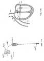
- Figure 1Ais a schematic illustration of the left ventricle of a heart showing blood flow during systole with arrows.
- Figure 1Bshows a cross-sectional view of the heart wherein a flexible stent is positioned at or near the mitral valve.
- Figure 2Ashows a cross-sectional view of the heart showing one or more magnets positioned around the annulus of the mitral valve.
- Figure 2Bshows an annular band with magnets that can be positioned on the mitral valve annulus.
- Figure 3shows a cross-sectional view of the heart identifying locations for placement of valves.
- Figure 4show a cross-sectional view of the heart with a pair of flaps mounted at or near the mitral valve.
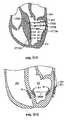
- Figure 5Ashows a schematic side view of the mitral valve leaflets with a flap positioned immediately below each leaflet.
- Figure 5Bshows a downward view of the mitral valve with a pair of exemplary flaps superimposed over the leaflets.
- Figure 5Cshows a pair of mitral valve leaflet flaps having complementary shapes.
- Figure 6Ashows a cross-sectional view of the heart with a membrane ring positioned at the mitral valve annulus.
- Figure 6Bshows a schematic view of the membrane ring, which includes an annular ring on which is mounted a membrane.
- Figure 7Ashows a schematic side view of the mitral valve leaflets failing to coapt.
- Figure 7Bshows a schematic top plan view of the mitral valve with the leaflets in an abnormal closure state such that a gap is present between the leaflets.
- Figure 7Cshows a schematic side view of the mitral valve leaflets with a blocker positioned between the leaflets.
- Figure 7Dshows a schematic top plan view of the mitral valve leaflets with a blocker positioned between the leaflets.
- Figure 8shows a cross-sectional view of a heart with a blocker device positioned partially within the left ventricle and partially within the left atrium.
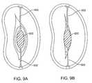
- Figures 9A-9Bshow schematic top plan views of the mitral valve leaflets with a blocker anchored between the leaflets during diastole and systole.
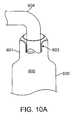
- Figures 10A-10Dshow a method of filling a fluid-tight blocker device.
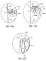
- Figures 11A-11Cshow various schematic views of another example of a blocker.
- Figure 12Ashows a schematic cross-sectional view another example of a blocker during systole.
- Figure 12Bshows a schematic cross-sectional view of the blocker from Figure 12A during diastole.
- Figure 12Cshows a schematic top plan view of the blocker from Figure 12A .
- Figures 12D-12Gshow an exemplary delivery of the blocker from Figure 12A .
- Figure 13Ashows a schematic top view of the heart during systole with another example of a blocker in position.
- Figure 13Bshows a schematic top view of the heart during diastole with the blocker from Figure 13A in position.
- Figure 13Cshows a schematic cross-sectional view of the heart during systole with the blocker from Figure 13A in position.
- Figure 13Dshows a schematic cross-sectional view of the heart during diastole with the blocker from Figure 13A in position.
- Figure 13Eshows a schematic cross-sectional view of a heart during systole with the blocker device of Figure 13A including a distal anchoring mechanism.
- Figure 13Fshows a schematic cross-sectional view of a heart during diastole with the blocker device of Figure 13A including a distal anchoring mechanism.
- Figure 14Ashows a schematic top view of the heart during systole with another example of a blocker in position.
- Figure 14Bshows a schematic top view of the heart during diastole with the blocker from Figure 14A in position.
- Figure 14Cshows a schematic cross-sectional view of the heart during systole with the blocker from Figure 14A in position.
- Figure 14Dshows a schematic cross-sectional view of the heart during diastole with the blocker from Figure 14A in position.
- Figures 14E-14Fshow schematic perspective views of the blocker from Figure 14A in open and closed orientations.
- Figures 15A-15Dshow schematic side views of a blocker having various types of a distal anchoring mechanism.
- Figure 15Eshows a schematic side view of the blocker of Figure 15A including a proximal anchoring mechanism.
- Figure 15Fshows a schematic cross-sectional view of a heart with the blocker device of Figure 15E positioned within the mitral valve.
- the chordae tendinae and papillary musclesare not shown for clarity.
- Figure 15Gshows a schematic top plan view of the mitral valve of Figure 15E .
- Figures 15H-15Ishow schematic, cross-sectional views of the heart illustrating a method of delivery of an anchored blocker.
- Figures 16A-16Cshow schematic cross-sectional views of the heart with other examples of a blocker in position wherein the blocker includes various anchoring mechanisms.
- Figure 17Ashows a schematic side view of a blocker having another example of a proximal anchoring mechanism.
- Figure 17Bshows a schematic cross-sectional view of a heart with the blocker device of Figure 17A positioned within the mitral valve.
- the chordae tendinae and papillary musclesare not shown for clarity.
- Figure 18Ashows a schematic side view of a blocker of a device in accordance with the claimed invention, the blocker having a proximal anchoring mechanism.
- Figure 18Bshows the proximal anchoring mechanism of the blocker of Figure 18A taken along circle B-B.
- Figure 18Cshows the proximal anchoring mechanism of Figure 18B in a clamped state.
- Figure 18Dshows a schematic cross-sectional view of a heart with the blocker of Figure 18A positioned within the mitral valve.
- the chordae tendinae and papillary musclesare not shown for clarity.
- Figures 19A-19Cshow schematic cross-sectional views of a blocker device having another example of an anchoring system.
- Figure 20shows a cross-sectional view of the heart wherein a one-way valve device is located in the left atrium.
- Figure 21Ashows a prosthetic ring that is sized to fit within a mitral valve.
- Figure 21Bshows another example of a prosthetic ring wherein a one-way valve is positioned inside the ring.
- Figure 22shows a prosthetic with one or more tongues or flaps that are configured to be positioned adjacent the flaps of the mitral valve
- Figure 23Ashows an example of one or more clips that are positioned on free edges of the leaflets.
- Figure 23Bshows pair of leaflets with a magnetic clip attached to the underside of each leaflet.
- Figure 23Cshows the leaflets coapted as a result of the magnetic attraction between the magnetic clips.
- Figure 23Dshows a pair of leaflets with a single clip attached to one of the leaflets.
- Figure 24shows a schematic, cross-sectional view of the heart with a wedge positioned below at least one of the leaflets of the mitral valve.
- Figure 25Ashows an artificial chordae tendon.
- Figures 25B and 25Cshow attachment devices for attaching the artificial chordae tendon to a heart wall.
- Figure 26shows a cross-sectional view of the heart with a first and second anchor attached to a wall of the heart.
- Figure 27shows a catheter that has been introduced into the heart.
- Figure 28shows a schematic view of a papillary muscle with a ring positioned over the muscle.
- Figure 29shows a cross-sectional view of the heart with one or more magnets attached to a wall of the left ventricle.
- Figure 30Ashows another example of a procedure wherein magnets are implanted in the heart to geometrically reshape the annulus or the left ventricle.
- Figure 30Bshows the heart wherein tethered magnets are implanted in various locations to geometrically reshape the annulus or the left ventricle.
- Figure 30Cshows the heart wherein magnets are implanted in various locations to geometrically reshape the annulus or the left ventricle.
- Figure 31shows another example of a procedure wherein magnets are implanted in the heart to geometrically reshape the annulus or the left ventricle.
- Figure 32shows a cross-sectional view of the left ventricle with a tether positioned therein.
- Figure 33shows a cross-sectional view of the left ventricle with a delivery catheter positioned therein.
- Figure 34shows a cross-sectional view of the left ventricle with the delivery catheter penetrating a wall of the left ventricle.
- Figure 35shows a cross-sectional view of the left ventricle with the delivery catheter delivering a patch to the wall of the left ventricle.
- Figure 36shows a cross-sectional view of the left ventricle with the delivery penetrating delivering a second patch.
- Figure 37shows a cross-sectional view of the left ventricle with two tethers attached together at opposite ends from the patches mounted in the heart.
- Figure 38shows a cross-sectional view of the left ventricle with a needle or delivery catheter passed transthoracically into the left ventricle LV to deliver a patch to the exterior of the ventricular wall.
- Figure 39shows a schematic, cross-sectional view of the left ventricle in a healthy state with the mitral valve closed.
- Figure 40shows the left ventricle in a dysfunctional state.
- Figure 41shows the left ventricle with a biasing member mounted between the papillary muscles.
- Figure 42shows the left ventricle with a suture mounted between the papillary muscles.
- Figure 43shows the left ventricle with a snare positioned around the chordae at or near the location where the chordae attach with the papillary muscles.
- Figure 44shows a leaflet grasping device that is configured to grasp and secure the leaflets of the mitral valve.
- Figures 45A-45Cshow the leaflet grasping device grasping leaflets of the mitral valve.
- Figure 46shows the left ventricle with a needle being advanced from the left atrium into the left ventricle via the leaflet grasping device.
- Figure 47shows the left ventricle with sutures holding the papillary muscles in a desired position.
- Figure 48shows a cross-sectional view of the heart with one or more clips clipped to each of the papillary muscles.
- Figure 49shows a cross-sectional view of the heart with tethered clips attached to opposed walls of the left ventricle.
- endovascularit is meant that the procedure(s) are performed with interventional tools, guides and supporting catheters and other equipment introduced to the heart chambers from the patient's arterial or venous vasculature remote from the heart.
- the interventional tools and other equipmentmay be introduced percutaneously, i.e., through an access sheath, or may be introduced via a surgical cut down, and then advanced from the remote access site through the vasculature until they reach the heart.
- the procedureswill generally not require penetrations made directly through the exterior heart muscle, i.e., myocardium, although there may be some instances where penetrations will be made interior to the heart, e.g., through the interatrial septum to provide for a desired access route.
- the described procedureswill usually be percutaneous and intravascular, many of the tools will find use in minimally invasive and open surgical procedures as well that includes a surgical incision or port access through the heart wall.
- the tools for capturing the valve leaflets prior to attachmentcan find use in virtually any type of procedure for modifying cardiac valve function.
- the atrioventricular valvesare located at the junctions of the atria and their respective ventricles.
- the atrioventricular valve between the right atrium and the right ventriclehas three valve leaflets (cusps) and is referred to as the tricuspid or right atrioventricular valve.
- the atrioventricular valve between the left atrium and the left ventricleis a bicuspid valve having only two leaflets (cusps) and is generally referred to as the mitral valve.
- the valve leafletsare connected to the base of the atrial chamber in a region referred to as the valve annulus, and the valve leaflets extend generally downwardly from the annulus into the associated ventricle. In this way, the valve leaflets open during diastole when the heart atria fill with blood, allowing the blood to pass into the ventricle.
- valve leafletsare pushed together and closed to prevent back flow of blood into the atria.
- the lower ends of the valve leafletsare connected through tendon-like tissue structures called the chordae, which in turn are connected at their lower ends to the papillary muscles.
- Interventionsmay be directed at any one of the leaflets, chordae, annulus, or papillary muscles, or combinations thereof. It will be the general purpose of such interventions to modify the manner in which the valve leaflets coapt or close during systole so that back flow or regurgitation is minimized or prevented.
- the left ventricle LV of a normal heart H in systoleis illustrated in Figure 1A .
- the left ventricle LVis contracting and blood flows outwardly through the tricuspid (aortic) valve AV in the direction of the arrows.
- Back flow of blood or "regurgitation" through the mitral valve MVis prevented since the mitral valve is configured as a "check valve” which prevents back flow when pressure in the left ventricle is higher than that in the left atrium LA.
- the mitral valve MVcomprises a pair of leaflets having free edges FE which meet evenly to close, as illustrated in Figure 1A .
- the opposite ends of the leaflets LFare attached to the surrounding heart structure along an annular region referred to as the annulus AN.
- chordae tendineae CT(referred to hereinafter as the chordae) which include plurality of branching tendons secured over the lower surfaces of each of the valve leaflets LF.
- the chordae CTin turn, are attached to the papillary muscles PM which extend upwardly from the lower portions of the left ventricle and interventricular septum IVS.
- atrioventricular valvesWhile the described procedures will be most useful with the atrioventricular valves, at least some of the tools described hereinafter may be useful in the repair of other cardiac valves, such as peripheral valves or valves on the venous side of the cardiac circulation, or the aortic valve.
- the described methodscan comprise accessing a patient's vasculature at a location remote from the heart, advancing an interventional tool through the vasculature to a ventricle and/or atrium, and engaging the tool against a tissue structure which forms or supports the atrioventricular valve.
- tissue structureBy engaging the tool against the tissue structure, the tissue structure is modified in a manner that reduces valve leakage or regurgitation during ventricular systole.
- the tissue structuremay be any of one or more of the group consisting of the valve leaflets, chordae, the valve annulus, and the papillary muscles, atrial wall, ventricular wall or adjacent structures.
- the interventional toolwill be oriented relative to the atrioventricular valve and/or tissue structure prior to engaging the tool against the tissue structure.
- the interventional toolmay be self-orienting (e.g., pre-shaped) or may include active mechanisms to steer, adjust, or otherwise position the tool.
- orientation of the interventional toolmay be accomplished in whole or in part using a separate guide catheter, where the guide catheter may be pre-shaped and/or include active steering or other positioning means such as those devices set forth in United States Patent Application Publication Numbers 2004-0044350 , 2004-0092962 and United States Patent Number 7,226,467 . In all cases, it will usually be desirable to confirm the position prior to engaging the valve leaflets or other tissue structures.
- Such orienting stepmay comprise positioning the tool relative to a line of coaptation in the atrioventricular valve, e.g., engaging positioning elements in the valve commissures and confirming the desired location using a variety of imaging means such as magnetic resonant imaging (MRI), intracardiac echocardiography (ICE), transesophageal echo (TEE), fluoroscopy, endoscopy, intravascular ultrasound (IVUS) and the like.
- imaging meanssuch as magnetic resonant imaging (MRI), intracardiac echocardiography (ICE), transesophageal echo (TEE), fluoroscopy, endoscopy, intravascular ultrasound (IVUS) and the like.
- heart disease in general, and valve repair in particularare treated by targeting the pacing of the heartbeat.
- heart diseaseis treated by introducing one or more pacing leads into a heart chamber.
- the pacing leadsare placed in contact with a heart muscle and are in electrical communication with a power source.
- the power sourceprovides paced electrical stimuli to the heart muscle.
- the electrical stimuliare provided during or immediately after systole to extend systolic contraction of the heart, thereby extending the range of systole during each heartbeat. This extension of systole extends the amount of time in which the heart muscle tightens when it would otherwise be relaxing, when there is most mitral regurgitation in diseased mitral valves.
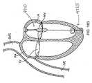
- FIG. 1Bshows a cross-sectional view of the heart wherein a flexible stent 100 is positioned at or near the mitral valve MV.
- the stent 100is annular and is sized and shaped to be positioned on the annulus of the mitral valve.
- the stent 100can transition between a collapsed state of reduced size and an expanded state of enlarged size relative to the collapsed state.
- the flexible stent 100can be percutaneously introduced into an individual's heart while being biased toward the collapsed state.
- the stentis advanced partially through the annulus of the mitral valve so that it is coaxially positioned within the annulus, as shown in Figure 1B .
- the stent 100is then secured to the annulus such that the stent exerts an inward force on the annulus thereby causing the annulus to resist dilation during diastole of the heart.
- a devicefor treating the mitral valve.
- the devicecan be a stent, such as the stent 100, that is sized to fit coaxially within an annulus of a mitral valve.
- the stentincludes a hollow frame.
- the framecan be annular such that it has a cross-sectional diameter that is sized such that an outer surface of the frame is in continuous coaxial contact with the annulus.
- the framealso includes one or more anchors protruding from it for securing the stent to the annulus.
- the anchorscan be prongs, barbs, protrusions, or any structure adapted to secure the stent to the annulus.
- the stentis flexible between an expanded configuration and a contracted configuration and is biased toward the contracted configuration so that it exerts an inward force on the annulus.
- the stent 100is delivered using a delivery catheter 10 that is advanced from the inferior vena cava IVC into the right atrium RA. Once the catheter 10 reaches the anterior side of the interatrial septum IAS, a needle 12 may be advanced so that it penetrates through the septum at the fossa ovalis FO or the foramen ovale into the left atrium LA. At this point, a delivery device can be exchanged for the needle and the delivery device used to deliver the stent 100. The catheter 10 can also approach the heart in other manners.
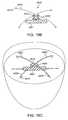
- Figure 2Ashows a cross-sectional view of the heart showing one or more magnets 205 positioned around the annulus of the mitral valve MV.
- a corresponding method of treating heart diseaseinvolves the use of magnets. The method includes percutaneously introducing at least a first magnet 205 into an individual's heart and securing it to the mitral valve MV annulus. At least a second magnet 205 is percutaneously introduced into the heart and advanced so that it is within a magnetic field of the first magnet. The second magnet is secured to the heart. The polarity of one of the two magnets is then cyclically changed in synchronization with the heart beat so that the magnets attract and repel each other in synchronization with the heart beat.
- the first magnettherefore moves in relation to the second magnet and exerts an inward closing force on the mitral valve during systole.
- the magnets 205can be positioned on an annular band 215 (shown in Figure 2B ) that is sized and shaped to be implanted on the annulus of the mitral valve.
- the band 215can be, for example, a stent.
- the magnets 205 or the annular band 215are delivered using a delivery catheter 10 that is advanced from the inferior vena cava IVC into the right atrium RA, as described above with reference to Figure 1 .
- a delivery catheter 10that is advanced from the inferior vena cava IVC into the right atrium RA, as described above with reference to Figure 1 .
- Any of the devices described hereincan be percutaneously delivered into the heart by coupling the device to a delivery device, such as a steerable delivery catheter.
- two or more magnetsare percutaneously introduced into an individual's coronary sinus such that they attract or repel each other to reshape the coronary sinus and an underlying mitral valve annulus.
- a method of treatmentincludes placing one or more one-way valves in one or more pulmonary veins of an individual either near the ostium of the vein or at some point along the length of the PV.
- Valves that may be usedmay be stentless valves such as designs similar to the TORONTO SPV® (Stentless Porcine Valve) valve, mechanical or tissue heart valves or percutaneous heart valves as are known in the art provided they are sized appropriately to fit within the lumen of the pulmonary vein, as shown in Figure 3 .
- valvescan be positioned in pulmonary vein orifices are represented by an "X".
- certain venous valve devices and techniquesmay be employed such as those described in United States Patent, 6,299,637 and 6,585,761 , and United States Patent Applications 20040215339 and 20050273160 .
- a valve prosthesis for placement in the ostia of the pulmonary vein from the left atriummay be in the range of 6-20mm in diameter.
- Placement of individual valves in the pulmonary vein ostiamay be achieved by obtaining trans septal access to the left atrium with a steerable catheter, positioning a guidewire through the catheter and into the targeted pulmonary vein, and deploying a valve delivery catheter over the guidewire and deploying the valve out of the delivery catheter.
- the valvemay be formed of a deformable material, such as stainless steel, or of a self-expanding material such as NiTi, and include tissue leaflets or leaflets formed of a synthetic material, such as is known in the art.
- a line of +++++ symbols in Figure 3represents a mid-atrial location above the mitral valve where a single valve can be positioned as disclosed later in this specification.
- Figure 4show a cross-sectional view of the heart with a pair of flaps mounted at or near the mitral valve.
- Figure 5Ashows a schematic side view of the mitral valve leaflets LF with a flap 300 positioned immediately below each leaflet.
- the flap 300can be contoured so as to conform at least approximately to the shape of a leaflet, or the flap 300 can be straight as shown in Figure 4 .
- Figure 5Bshows a downward view of the mitral valve with a pair of exemplary flaps superimposed over the leaflets LF.
- the flapscan have complementary shapes with a first flap having a protrusion that mates with a corresponding recess in a second flap.
- a first flap 300 with an attachment end 305 and a free end 310is provided.
- the attachment end 305 of the first flap 300is secured to the inside wall of the ventricle below the mitral valve.
- a second flap 315 with an attachment end 320 and a free end 330is provided and is also secured to the inside wall of the ventricle below the mitral valve.
- the first and second flaps 300, 315are oriented so that they face each other and the free ends 310, 330 are biased toward each other and approximate against each other during systole.
- This systemprovides a redundant valving system to assist the function of the native mitral valve.
- Figure 6Ashows a cross-sectional view of the heart with a membrane ring 610 positioned at the mitral valve annulus.
- Figure 6Bshows a schematic view of the membrane ring 610, which includes an annular ring on which is mounted a membrane.
- the membraneincludes a series of perforations 615 extending through the membrane surface.
- One or more anchor devices, such as prongs,can be located on the ring for securing the ring to the mitral valve.
- a device for treating heart disease in general and defective or diseased mitral valvesin particular includes a disc having a ring, a membrane stretched across an opening of the ring, and one or more anchors for securing the disc to an annulus of a mitral valve.
- the discis sized to cover the annulus of the mitral valve, and the membrane includes one or more perforations that permit one way fluid flow through the disc.
- a deviceknown as a blocker or a bladder which improves the functioning of a heart valve by providing a surface against which valve leaflets may coapt.
- the blocker devicemay be used to improve the functioning of any heart valve (tricuspid, aortic, mitral) though for the purpose of brevity most examples will be in relation to the mitral valve.
- a blocker devicecan be used to treat mitral valve disease such as mitral regurgitation (MR).
- MRmitral regurgitation
- Blocker devicescan also be used for treating other valve diseases such as tricuspid valve regurgitation and aortic insufficiency.
- FIG. 7Ashows a schematic side view
- Figure 7Bshows a top plan view of a mitral valve with the leaflets LF in an abnormal closure state such that a gap G is present between the leaflets.
- Leaflets that fail to coaptcan result in valve regurgitation (as represented by the arrow RF).
- a blocker deviceUpon positioning within, on, or around the valve, a blocker device can provide a surface against which at least a portion of the valve leaflet or leaflets can coapt.
- the blockerassists the valve preventing regurgitation by increasing the coaptation area of the valve leaflets LF and/or decreasing the coaptation depth of the leaflets LF.
- Increasing coaptation of the valvecan be accomplished by placing a blocker in the diseased valve orifice and providing a surface against which the leaflets LF can coapt therein closing the valve during systole.
- the blockercan be conformable such that the leaflets press against and seal with the blocker during systole.
- the blockerassists in closing the valve without altering the shape of the annulus AN and/or repositioning the papillary muscles PM.
- the blockercan conform to the leaflet shape providing better sealing to minimize and block mitral valve regurgitation.
- Figures 7C and 7Dshow an example of a blocker 630 positioned such that the blocker 630 is coaxially aligned between the leaflets LF along the line of coaptation of the leaflets LF.
- the blocker 630can provide a surface against which at least a portion of the leaflets LF can seal and thus serve as a coaptation device for the leaflets.
- An atrial portion of the blocker 630can extend into the left atrium, and a ventricular portion of the blocker 630 can extend into the left ventricle.
- the configuration of the blockers described hereincan vary.
- the blockercan be solid, semi-solid or have a mesh-like configuration.
- the blockercan also have a variety of shapes such that it is optimized based on the geometry of the valve, the alignment of the leaflets and the size/shape of the valve orifice.
- the blockercan have a spherical, ellipsoid, wing-like, t-shape, x-shape, y-shape, annular, sheet, rectangular, umbrella-shape or other geometry. It should be understood that any of the blocker examples described herein may be used with any of the different anchoring mechanisms described herein.
- Applicantswill omit an explicit description of each combination of blocker example and anchoring mechanism. Additionally, Applicants describe herein different methods for accessing heart valves and for implanting the blocker device within the heart. The different blocker devices are amenable to several different methods of access and implantation. Applicants will provide representative descriptions of how to access the heart vale and implant the blocker. However, for the sake of brevity, Applicants will omit an explicit description of each method of access/implantation with respect to each blocker example.
- the blockercan be expandable or can include an expandable region.
- the expandable regioncan be self-expanding or actively expanded such as by fluid filling.
- a blockercan include a "balloon"-type, compliant expandable region such as a sealed, fluid-filled bladder
- a blockercan include an expandable frame or mesh covered by a compliant material ("covered stent" type blocker).
- a blockercan include an expandable region composed of a compressed, sponge-like material.
- a blockercan include an expandable region that takes on a blocking geometry, for example, a T-shape or other shape with an enlarged "head" at the atrial side of the valve.
- a blockercan include an expandable region that is dynamic and moves with the changes in pressure and flow of the diastolic/systolic cycle.
- a blockercan include an expandable region that sits like a diaphragm across the valve to block regurgitation.
- Materials suitable for construction of the blockercan vary, for example, synthetic polymers, biological polymers, metals, ceramics, and biological materials.
- Suitable synthetic polymerscan include fluoroethylenes, silicones, urethanes, polyamides, polyimides, polysulfone, polyether ketones, polymethyl methacrylates, and the like.
- Suitable metalscan be composed from a variety of biocompatible elements or alloys. Examples include shape-memory metal (e.g. Nitinol), titanium, Ti-6AL-4V, stainless steel alloys, chromium alloys, and cobalt alloys.
- the materialscan also be subjected to surface modification techniques to make them selectively bioreactive or non-reactive, including texturing, surface coatings, electrical modification, coating or impregnation of biologically derived coatings and a variety of growth-healing modifications.
- Blocker examples described hereincan be delivered using interventional tools, guides and supporting catheters and other equipment introduced to the heart chambers from the patient's arterial or venous vasculature remote from the heart.
- the blockers described hereincan be compressed to a low profile for minimally-invasive or percutaneous delivery. They can be advanced from the remote access site through the vasculature until they reach the heart.
- the blockerscan be advanced from a venous site such as the femoral vein, jugular vein, or another portion of the patient's vasculature. It is also appreciated that blockers can be inserted directly into the body through a chest incision.
- a guidewirecan be steered from a remote site through the patient's vasculature into the inferior vena cava (IVC) through the right atrium so that the guidewire pierces the interatrial septum.
- the guidewirecan then extend across the left atrium and then downward through the mitral valve MV to the left ventricle.
- a cathetercan be passed over the guidewire and used for delivery of a blocker device.
- Blocker examples described hereincan also be delivered using a catheter advanced through retrograde access through, for example an artery, across the aortic arch and the aortic valve and to the mitral valve by way of the ventricle.
- Alternative delivery methods of blockers described hereincan include inserting the blocker through a small access port such as a mini-thoracotomy in the chest wall and into the left ventricle apex. From there, the blocker can be advanced through the left ventricle into the left atrium. It should be appreciated that the device can also be delivered via the left atrial wall as well.
- Imaging meanssuch as magnetic resonant imaging (MRI), intracardiac echocardiography (ICE), transesophageal echo (TEE), fluoroscopy, endoscopy, intravascular ultrasound (IVUS) and the like.
- MRImagnetic resonant imaging
- ICEintracardiac echocardiography
- TEEtransesophageal echo
- fluoroscopyendoscopy
- IVUSintravascular ultrasound
- the blockercan be anchored and/or expanded into position.
- a sheathcan be used to compress the blocker during insertion such that upon retraction the sheath allows for expansion of the blocker.
- Expansion mechanisms of the expandable portion of the blockercan vary. In an example expansion of the blocker can occur through a passive, self-expansion mechanism.
- the blockercan be actively expanded such as by infusing a filling fluid through the catheter lumen into a sealed expandable portion. Upon expansion of the blocker, mitral regurgitation and ventricular filling can be assessed to determine whether expansion of the blocker is sufficient.
- the blockercan be reversibly coupled to the catheter or sheath such that the blocker can be retracted back into the catheter or advancing the sheath if repositioning is necessary. If the result is not satisfactory, the blocker can be retracted, repositioned, re-deployed or removed.
- the blockerincludes one or more anchors
- materials suitable for the constructions of the anchorscan vary as well.
- Materialscan include biocompatible and/or coated, impregnated, or otherwise treated with a material or other materials to impart biocompatibility, shape-memory metal (e.g. Nitinol and Nitinol alloys), stainless steel and stainless steel alloys, titanium and titanium alloys, cobalt-chrome alloys, wire-mesh, and the like.
- the anchorcan also be constructed of materials such as thread made of, for example, nylon, braided nylon, PTFE, ePTFE, medical-grade sutures and the like or combinations of the above.
- Figure 7Dillustrates an example of a blocker 630 that is attached or anchored to the mitral valve at opposite edges E of the gap G (shown in Figure 7B ).
- the blocker devices described hereincan be attached or anchored to various locations adjacent to or on the valve being treated. It should also be appreciated that the blocker device can be positioned without anchors.
- the blocker devices described hereincan include proximal anchor mechanisms that secure to tissues at or superior to the level of the valve, for example the atrium, coronary sinus, interatrial septum or upper surface of the annulus or valve leaflets. The proximal anchors can act to suspend the blocker between the valve leaflets.
- the blocker devices described hereincan include distal anchor mechanisms that secure to tissues at or inferior to the level of the valve, for example, the ventricle wall, interventricular septum, or the lower surface of the annulus or valve leaflets.
- a distal portion of the blockercan be secured to the chordae tendinae and/or the papillary muscle.
- the blockeris secured by a combination of anchoring mechanisms, for example both proximally and distally to the level of the valve. It should be appreciated that a combination of anchor types can be used and that the anchors can secure the blocker to different portions of the heart including the external wall of the heart.
- the timing of the deployment of the anchoring mechanismscan vary.
- the anchoring mechanismscan be deployed prior to or after the blocker is in place between the leaflets.
- the blockermay include a distal coiled screw anchor that is screwed into the myocardium of the left ventricle, for example, by rotating the catheter prior to placement of the blocker between the leaflets.
- the blockerincludes a chordal attachment anchor that is delivered prior to deployment of the blocker from the catheter tube. In these examples, once the anchors are in place the blocker is positioned between the leaflets and expanded or allowed to expand. It should be appreciated, however, that expansion can occur prior to anchoring the blocker or that no anchoring mechanism be used at all.
- the anchoring mechanismscan be adjusted after deployment such that they release the heart tissue, for example, if the results of the blocker are not satisfactory.
- the cathetercan be used to rotate the blocker and unscrew the coiled anchors from their tissue attachment. Thereafter the device can be re-positioned, re-deployed or removed. If the result is satisfactory, the catheter can be detached from the blocker and withdrawn.
- FIG 8shows an example of a blocker that is an expandable blocker 600.
- the blocker 600can be a fluid-tight expandable element or bladder that can be filled with a fluid, including a liquid or a gas.
- the blocker 600can be positioned partially within the left ventricle and partially within the left atrium.
- the bladder 600can be placed across the mitral valve MV between the left atrium LA and the left ventricle LV.
- the volume of the blocker 600can expand on the left atrial LA side of the heart, providing a baffle or sealing volume to which the leaflets of the mitral valve coapt.
- the blocker 600also can block the flail and billowing of a leaflet into the left atrium.
- the blocker 600can also have enlarged portions on both the atrial and ventricular sides with a generally narrower transition zone therebetween. The enlarged portions can maintain the blocker in position and prevent the blocker from migrating into the atrium or the ventricle.
- the blocker 600can also be formed on a cage or other infrastructure to position it within the line of coaptation of the mitral valve.
- the blocker 600can include one or more anchors for securing the blocker to an annulus of a mitral valve.
- the mid portion of the blocker 600can be secured to the annulus of the mitral valve such that the mid-portion remains stationery while the atrial and ventricular portions expand and contract passively between the atrium and ventricle due on pressure differentials during systole and diastole.
- Figures 9A-9Bshows an example of a blocker 600 that includes an anchor 602 on each end of the blocker 600.
- the anchor(s) 602can be positioned near the mid portion or narrower portion of the blocker 600 and secure the blocker 600 to the annulus.
- the blocker 600can be an expandable element that can be filled with a fluid, such as a liquid, gel, gas or other material.
- Figures 10A-10Dillustrate methods of filling the blocker 600 upon implantation between the valve leaflets.
- the blocker 600can include a neck region 601 near its proximal end having a valve 603 through which filling material can be infused.
- the valve mechanism or configurationcan vary.
- the valve 603can be a duckbill valve having one or more flexible "flaps" that close and seal against one another.
- the delivery catheter or a filing tube 604can be inserted through the valve 603 such that an opening at the distal end of the filling tube 604 extends within a lumen 605 of the blocker 600.
- the filling tube 604can be removed from the valve 603 by withdrawing it in a proximal direction.
- the flaps of the valve 603can then close and prevent escape of the filling material delivered to the lumen 605 of the blocker 600.
- the filled lumen 605 of the blocker 600can have a pressure that is higher than the pressure on the proximal side of the valve which can aid in urging the valve flaps towards one another and closing the valve such that filling material does not flow out of the blocker 600 as shown in Figure 10B .
- FIGs 10C-10Dillustrate an alternative valve design which involves the use of a spring clip 606.
- the blocker 600has a neck region 601 that is damped on an external surface by a clip 606 or other spring-loaded mechanism.
- the clip 606can be initially held open, for example, by the catheter or filling tube 604 inserted through the neck of the blocker 600. After filling of the blocker 600 with material, the filling tube 604 can be removed and the clip 606 spring closed around the neck region 601 of the blocker 600. The clip 606 in its closed position can seal off the proximal end of the blocker 600 (see Figure 10D ).
- Figures 11A-11Cshow another example of a blocker 3800.
- the blocker 3800can be oriented along the leaflet coaptation.
- the blocker 3800can extend a portion of or the full-width of leaflet coaptation.
- the blocker 3800can allow for both leaflets LF to coapt to and open away from the blocker 3800.
- the blocker 3800can include a central bar 3805 that can optionally extend downward through the gap G between the leaflets LF.
- the blocker 3800can include anchors 3820 that upon positioning within the valve are oriented near both leaflet commissures C and push outward against the atrial wall.
- the anchors 3820can have one or more frictional elements to improve their interface with the surrounding anatomy.
- the blocker 3800also can include an expandable anchor ring 3810 (either self-expanding or balloon-type expanding) coupled to the bar 3805 and/or the anchors 3820 that extends around the circumference of the annulus AN.
- the circumferential anchor ring 3810can expand and push out against the atrial wall at the annulus level thereby retaining the bar 3805 in position between the leaflets LF.
- the blocker 3800 and anchor ring 3810can include a self-expanding mesh covered with a compliant material for improved sealing and leaflet coaptation.
- blocker 3800 and anchor ring 3810are balloon-expanded or filled with a fluid material such as two-part epoxy, resin, polymer, hardening or hardenable material, Hydrogel material, saline or other material.
- a fluid materialsuch as two-part epoxy, resin, polymer, hardening or hardenable material, Hydrogel material, saline or other material.
- the blocker 3800 and anchor ring 3810are made of a compressed, sponge-like material that expands.
- Various features of the blocker 3800can be used in combination with any of the blocker examples described herein.
- Figures 12A-12Gshow another example of an expandable blocker.
- the blocker 4000can include a frame 4005 having an upper portion 4010 that is oriented within the left atrium above the level of the annulus, a lower portion 4020 that is oriented within the left ventricle below the level of the annulus and a middle portion 4025 that is oriented at the level of the annulus.
- the frame 4005can be generally flexible and can be made from shape-memory metal (e.g. Nitinol) or an expandable wire mesh or the like.
- the frame 4005can be covered by a membrane or coating 4030 that can be constructed of a flexible, compliant material such as silicone rubber or a saline-filled balloon structure.
- the frame 4005need not be flexible.
- the blocker 4000can be positioned over the gap G between the leaflets LF along the line of coaptation C.
- the upper portion 4010 of the frame 4005can rest above the valve plane such that it contacts or rests upon the anterior and posterior annulus AN.
- the lower portion 4020 of the frame 4005can extend under the valve leaflets such that it does not come in contact with the annulus AN as shown in Fig 12A-12C .
- the frame 4005can be held in place during systole and diastole due to a spring force of the frame 4005.
- the blocker 4000can plug the gap G between the anterior and posterior leaflets LF, but does not require sutures or anchors due to the configuration of the upper and lower frame portions 4010, 4020 relative to the anatomy.
- the upper portion 4010 of the frame 4005can provide anchoring support through its interaction with the annulus wall and prevent the blocker 4000 from moving during heart function.
- the lower portion 4020 of the frame 4005can capture the leaflets LF and close the gap G between the leaflets LF as well as keeping the blocker 4000 in position within the valve. It should be appreciated that the frame 4005 can also be held in place using one or more anchors.
- the lower portion 4020 of the blocker 4000can move in response to the changes in pressure during the diastolic/systolic cycle such that the leaflets LF are captured between the lower portion 4020 and the upper portion 4010 of the frame 4005.
- the lower portion 4020 of the frame 4005can include a pair of arms 4035, 4040 that move upward and downward. During systole the arms 4035, 4040 move upward flattening out against the valve leaflets LF trapping them between the arms 4035, 4040 and the upper portion 4010 of the frame 4005. During diastole, the blocker 4000 arms 4035, 4040 can spring back to a relaxed position. It should be appreciated that movement of the blocker arms 4035, 4040 is optional and that the arms 4035, 4040 can also be fixed in orientation and not move during the diastolic/systolic cycle.
- Figures 12D-12Gillustrate a method of delivery of the blocker 4000.
- the blocker 4000can be oriented within the catheter 4045 such that the upper portion 4010 and lower portion 4020 are each compressed into a low profile.
- the catheter 4045can be fed through the valve such that upon withdrawal of the catheter 4045 the arms 4035, 4040 of the lower portion 4020 can relax into position below the leaflets LF.
- the catheter 4045can be further withdrawn such that the upper portion 4010 can be deployed and relaxes into position above the valve leaflets LF.
- the diameter of the upper portion 4010prevents it from passing through the valve.
- FIGS 13A-13Fillustrate an example of a blocker 4100 having a folded configuration and including flaps or arms that can "tent" or fill during systole.
- the flaps of the blocker 4100open up and tent as they fill with the flow blocking mitral regurgitation.
- diastoleblood flows from the LA into the LV through the open mitral valve.
- the flapsmove downward and the blocker 4100 folds to allow blood to flow past the blocker 4100 passively allowing diastolic flow.
- the blocker 4100can also incorporate a hinge feature to aid in the folding of the flaps on either side of the central region.
- the flapscan passively articulate or rotate about the pivot axis of the hinge while the hinge remains fixed with the cardiac circulation.
- the blocker 4100can include a frame constructed of a flexible material, for example, the blocker 4100 can be constructed of a shape-memory metal (e.g. Nitinol) or a flexible semi-rigid polymer such as Nylon or PTFE.
- the blocker 4100can be formed into a flexible sheet or other shape.
- the blocker framecan be covered by a compliant membrane or other material to improve sealing function.
- the framecan include the pair of arms positioned at least in part below the level of the annulus. The frame can be moveable between a fluid flow-allowing position and a fluid flow-blocker position in response to changes in heart chamber pressure during the heart cycle.
- the pair of armscan tent upwards against the lower surface of a valve leaflet, for example during systole into the fluid flow-blocking position.
- the pair of armscan collapse downward away from the lower surface of the valve leaflet, for example during diastole into the fluid flow-allowing position.
- the blocker 4100can be tethered to one or more anchors 4105.
- the one or more anchors 4105can include a tether connecting a portion of the frame of the blocker 4100 to an expandable portion of the anchor 4105 positioned, for example, within the coronary sinus (see Figures 13A-13B ).
- the tethercan also connect the blocker 4100 to an anchor that can be positioned distally, for example within the left ventricular wall (see Figures 13E-13F ).
- the tethercan connect to the frame, for example at a portion aligned near an outer edge E of the gap G.
- the framecan include a stationary portion coupled to a proximal portion of the pair of arms.
- the stationary portioncan be positioned above the level of the annulus and have a long axis oriented orthogonal to the line of coaptation.
- the tethercan connect to the frame at the stationary portion near a region aligned near an outer edge of the gap.
- the tethercan connect to the frame at a lower surface of the stationary portion, for example, when interconnecting the blocker to a location distal to the valve such as the wall of the left ventricle.
- the blocker 4200can act as a "baffle" and change orientation, such as by swiveling, rotating or pivoting, thereby opening and closing the valve.
- the change in orientation of the blocker 4200can be passive in that the blocker opens and closes as a result of the change in pressure and flow reversal during the systolic/diastolic cycle.
- the orientation change of the blocker 4200can be semi-active, for example, a spring-loaded mechanism that orients the blocker 4200 in a first direction and changes orientation, for example, due to blood flow in a second, opposite direction.
- the blocker 4200can operate as a butterfly valve.
- the blocker 4200can be a planar structure having a rectangular shape such that it is longer than it is wide (see Figures 14E and 14F ).
- the blocker 4200can be aligned such that the long axis of the blocker 4200 spans between the leaflets LF and blocks the flow of blood through the gap G (see Figure 14A and 14C ).
- the blocker 4200can swivel approximately 90 degrees such that the long axis of the blocker 4200 aligns with the gap G and flow is allowed through the valve ( Figure 14B and 14D ).
- the blocker 4200swivels between a closed position during systole and an open position during diastole regulating flow through the valve as a result of blood flow during the cardiac cycle.
- the blocker 4200can be tethered to an anchor 4205 such as a stent or similar structure.
- the blocker 4200can be constructed of a biocompatible material such as a metal or polymer, for example an implantable stainless steel, titanium, or Nitinol.
- the blocker 4200can be generally rigid and the anchors 4205 can be flexible.
- Various features of the blockers 4100, 4200can be used in combination with any of the blocker examples described herein.
- the blockers described hereincan include one or more anchoring mechanisms.
- the blocker devices described hereincan include proximal or mid-portion anchor mechanisms that can be secured to the atrium or to the septum or to the leaflets or annulus. In other examples, the blocker can be secured distally such as to the ventricle or the chordae tendinae or the papillary muscle. It should be appreciated that a combination of anchoring mechanisms can be incorporated and that the anchors can secure the blocker to different portions of the heart.
- the blocker devices described hereincan also be used without the aid of an anchor.
- Figures 15A-15Dillustrate blocker examples incorporating distal anchors.
- the distal anchors illustrated in FIGs. 15A-15Dcan be used with any of the blocker concepts described in this disclosure, and explicitly not limited to the blocker 4301 depicted in FIG. 15A .
- Figure 15Aillustrates a blocker 4300 that includes a distal anchor 4305 that is a coiled screw type of anchor, which can embed into the heart wall.
- the blocker 4300includes multiple spring wire supports 4310 that prop up the expandable region 4301 from the coiled screw anchor 4305.
- the spring wire supportscan provide additional axial stability.
- additional axial stabilitycan also be provided to the blocker 4300 by additional "leg" supports 4315 as an alternative to spring wire supports 4310.
- Another example of a blocker shown in Figure 15Dcan include an external anchor 4320 that can be used, for example, with a blocker delivered through the left ventricular wall near the apex of the heart to the exterior of the heart.
- the blocker 4500includes one or more support wires 4510 extending proximally from the expandable region 4501 in addition to the distal anchor 4505.
- the support wires 4510can be sized to engage the muscular annulus around the mitral valve MV as well as tissue of the left atrium LA.
- the support wires 4510can be sharp or include barbs 4515 to hold onto the tissue.
- the support wires 4510can be retracted within a sheath or catheter and then relax or spring outward upon retraction of the sheath to engage the annulus or left atrium.
- the support wires 4510can be sized to engage the annulus and/or the left atrial tissue.
- Figures 15H-15Ishow method of delivery of an anchored blocker, such as the blockers shown in Figures 15A-15G , using a catheter 4045 and a retractable sheath 4110 compressing the expandable region 4301 of the blocker 4300 to a delivery configuration inside an inner lumen of the sheath 4110.
- the catheter and sheath system having a compressed blocker thereincan be advanced from a venous site, such as accessed from a femoral vein through the inferior vena cava IVC and across the interatrial septum to the mitral valve as is described herein.
- the catheter 4045can be positioned using guidance methods such as echoguidance or other guidance method known in the art.
- the distal anchor of the blocker 4300can extend out the distal end of the retractable sheath 4110 and come into contact with the ventricle wall upon advancement of the blocker 4300.
- the catheter 4045can be rotated to advance the anchor 4305 into the left ventricle myocardium.
- the anchor 4305can be embedded in the ventricle wall.
- An anchor 4320can also be implanted that it is external to the heart (see Figure 15I ).
- An alternate delivery methodcan include through a small access port such as through the chest wall, such as through a mini-thoracotomy, and into the apex of the left ventricle.
- the devicecan be advanced from the left ventricle into the left atrium and then the sheath retracted to open the blocker.
- the surgeoncan then implant an external anchor 4320 upon positioning the blocker between the valve leaflets and then close the access ports.
- the blocker 4300can self-expand upon retraction of the sheath 4110.
- the leafletscan then coapt against the blocker and prevent mitral regurgitation (MR). If the MR result is unsatisfactory in some way, the sheath 4110 can be re-advanced to compress the expandable portion 4301 of the blocker 4300.
- the catheter 4045can then be rotated to either unscrew or screw the distal anchor 4305 and the distance between the blocker 4300 and the base of the ventricle wall modified.
- the blockercan be re-positioned, re-deployed and removed. If the MR result is satisfactory, the blocker can be detached from the catheter and the catheter and sheath retracted and withdrawn from the patient.
- the expandable regions 4301, 4501 of the blockers 4300, 4500 described abovecan be inflatable bladders or made from a compliant material. It should be appreciated that other configurations of expandable regions are considered. It should also be appreciated that the anchors and supports described with respect to the blocker examples of Figures 15A-15I can be used with other examples of blockers described herein.
- Figures 16A-16Cshow more examples of a blocker 4400 having a distal anchoring mechanism 4405.
- the blocker 4400is held in place by distal anchors 4405 that attach to the chordae tendinae CT and/or papillary muscle PM.
- the anchors 4405can include various attachments 4410 including loops that wrap around the CT or clips that attach to the PM.
- the example of Figure 16Bshows a blocker 4400 where the geometry of the proximal region of the blocker 4400 further supports the blocker and prevents it from passing through the leaflets LF from the atrial side.
- This examplealso shows an anchor 4405 (in this case a suture line attachment that attaches to the papillary muscle PM).
- the anchors 4405 and/or attachments 4410can be shape-memory metal (e.g. Nitinol) with coil set shape that wrap around the chordae.
- the blocker 4400can incorporate a rail system such that after the anchors 4005 are in place the blocker 4400 can be advanced over a guide wire or other rail system to slide the blocker 4400 into the desired location.
- the rail systemcan be used to lock on the anchors 4405 upon expansion.
- Various blocker anchoring mechanismscan be used and can be used in combination with any of the blocker examples described herein.
- Figure 16Cshows an example of a blocker 4400 incorporating another example of a distal anchor system or support structure 4415.
- the support structure 4415e.g. wires, plastic elements or inflatable legs
- the support structure 4415can be advanced distally from the blocker 4400 such that it contacts the inner wall of the left ventricle LV near the apex AX.
- the support structure 4415can curve back around up toward the valve structure, pressing against and pushing up from the apex AX and against the ventricle wall.
- the support structure 4415can terminate under the leaflets LF against the ventricle wall.
- the blocker 4400can lock the position of the support structure 4415 upon expansion.
- the blockers of Figures 16A-16Ccan be contained within a catheter or sheath during delivery and advanced to the left atrium.
- the distal anchors 4405can initially wrap around (or clip or pierce or insert, depending on the example used) the chordae and/or papillary muscles PM before the blocker 4400 exits the catheter guide tube.
- the blocker 4400can self-expand upon retraction of the catheter or sheath or be inflated prior to retraction of the catheter or sheath as described above. Expansion of the blocker 4400 can lock into position the chordae or PM attachment. Deflation or re-compression of blocker 4400 can allow movement and repositioning of the blocker.
- the cathetercould also be advanced from a femoral site over the aorta through the aortic valve and retrograde to the mitral valve.
- the distal anchors 4405can grasp and wrap around the chordae according to a variety of methods, for example such as described in U.S. Publication No. 2004-0030382 .
- Blockers described throughout this disclosurecan include a combination of anchor mechanisms.
- the blockerscan include either or both distal and proximal anchors.
- Such a combination of anchorsprovides additional axial stability, adjustability and positioning.
- the distal anchors as described abovecan attach, for example, to the ventricle wall or papillary muscle or chordae and the like.
- the proximal anchors of the blockercan attach to the annulus, the atrial wall, valve leaflets and/or the interatrial septum.
- the blocker 4600includes one or more of a proximal anchor mechanism 4610 and/or a distal anchor 4605.
- the proximal anchorcan have a "clam-shell” or “double-umbrella” design configured to engage the septum between the left and right atria in the heart.
- the illustration provided in FIG. 17Aincludes both proximal and distal anchors; however, the use of only a proximal or only a distal anchor is contemplated.
- a wire 4615extends from the expandable region 4601 to one or more septal anchors 4620. This mechanism provides adjustability of position to optimize the result.
- the length of the wire 4615can be adjusted by applying a proximally-applied force such that the wire 4615 slides in a proximal direction through the septum and the septal anchors 4620.
- a crimp or other clamping devicecan be advanced in a distal direction over the wire 4615 until it abuts a septal anchor 4620, for example the septal anchor 4620 in the right atrium.
- the crimpcan be deployed such that it is affixed to a portion of the wire 4615 near the septal anchor 4620 and prevents the wire 4615 from sliding back through the septal anchors 4620.
- the wire 4615can extend from a proximal portion of the expandable region 4601 of the blocker 4600.
- the wire 4615can extend from the distal anchor 4605, through the expandable region 4601 and out the proximal end of the blocker 4600.
- adjustment of the wire 4615can also adjust the length of the wire 4615 between the anchor 4605 and the expandable region 4601 of the blocker 4600.
- an expandable blocker 4701can include a proximal anchor mechanism 4710.
- the proximal anchor mechanism 4710includes a sleeve 4715 that can be advanced and brings together one or more pairs of sharp angled wires 4720 that grab onto myocardium in either the ventricle or atrium or both.
- the blocker 4701can be expanded such as by inflation such that it urges the sleeve 4715 in a proximal direction (arrow A).
- the inner walls of the sleeve 4715presses against the pairs of angled wires 4720 moving them towards one another.
- the diameter of the expanded blocker 4701can be larger than the inner diameter of the sleeve 4715. This prevents the sleeve 4715 from being retracted in the distal direction back over the blocker 4701.
- the expanded blocker 4701can simultaneously block regurgitation through the valve leaflets, deploy the proximal anchor and lock the proximal anchor in place.
- the expandable blocker 4701can be depleted of filling material such that the outer diameter of the expandable blocker 4701 is reduced and the sleeve 4715 can be withdrawn or retracted over the outer diameter of the blocker 4701.
- the embodiment of Figure 18Ais shown having a distal anchor 4705, but it should be appreciated that the embodiment need not include a distal anchor.
- Figure 18Dshows another example of a blocker 4700 incorporating both a proximal anchoring mechanism 4710 as well as a distal septal anchor 4725; however, it should be understood that the blocker may include only the distal anchor 4725, only the proximal anchor 4710, or both proximal and distal anchors.
- FIGS 19A-19Cshow another example of a proximally-anchored blocker system 4800.
- the blocker system 4800includes a blocker 4801 which may be any of the blockers disclosed throughout this disclosure.
- the blocker 4801may be formed of a resilient material and/or may be a liquid or gas-filled bladder.
- an anchor system 4810can be actuated.
- the anchor system 4810can include an anchor wire lock ring 4815, a plurality of support arms 4820 and a blocker lock ring 4825.
- the anchor system 4810deploys in a manner similar to an umbrella's arms.
- the anchor wire lock ring 4815can be slid proximally and distally to spread or retract the support arms 4820.
- the support arms 4820can be made of a shape memory material such as Nitinol or the like such that the support arms are biased to extend or spread.
- a biasing membersuch as a spring or the like can be used to bias the support arms 4820 to extend.
- the anchor system 4810can omit a biasing member such that support arms 4820 can be manually opened by extending the ring 4815.
- the support arms 4820can anchor to the atrial side of the valve such as by grasping or penetrating the annulus or other structures near the valve, such as with barbs 4818 or other features that improve the grip of the support arms 4820 to the adjacent anatomy.
- the support arms 4820can also anchor due to a spring force or pushing out against the atrial wall.
- the support arms 4820can also have a length that is adjustable, for example, the support arms 4820 can slide through the anchor lock ring 4815 such that arm length can be adjusted for proper contact with the adjacent structures. Such a configuration can be self-adjusting.
- the anchor lock ring 4815can lock onto the blocker lock ring 4825 to fix the blocker 4800 in its deployed state, such as by a snap-lock type configuration.
- Figure 20shows a cross-sectional view of the heart wherein a one-way valve device 700 is located in the left atrium.
- the valve deviceis represented schematically in Figures 21A-B .
- a corresponding method of treating heart diseaseincludes introducing a one-way valve device 700 into the left atrium of an individual's heart proximal the mitral valve.
- the valve device 700is configured to permit fluid flow in one direction while preventing fluid flow in an opposite direction.
- the valve devicecan have various structures.
- the devicecan comprise a valve that is mounted on a stent that is sized to be positioned in the left atrium.
- Valvesthat may be used, for example may be stentless valves such as the TORONTO SPV® (Stentless Porcine Valve) valve, mechanical or tissue heart valves or percutaneous heart valves as are known in the art.
- the outer wall of the one-way valve deviceis sealed to the inner wall of the atrium so that a fluid-tight seal is formed between the outer wall of the one-way valve device and the inner wall of the left atrium.
- the valve devicecan include a seal member that is configured to seal to the inner wall of the atrium.
- FIG 21Ashows a prosthetic ring 800 that is sized to fit within a mitral valve annulus
- the ring 800includes one or more anchors 805 that extend around the periphery of the ring 800.
- one or more struts 810 strutsextend across the diameter of the ring, and can be made of a material that includes shape-memory metal (e.g. Nitinol) or magnetic wires for selectively adjusting the shape of the ring.
- the strutscan also be instrumental in baffling mitral valve leaflet "flail”.
- Figure 21 Bshows another example of a prosthetic ring 807 wherein a one-way valve 815 is positioned inside the ring such that blood flow BF can flow through the valve in only one direction.
- the valvecan be manufactured of various materials, such as silicone.
- Figure 22shows a prosthetic with one or more tongues or flaps 910 that are configured to be positioned adjacent the flaps of the mitral valve.
- the prostheticincludes a ring 900 sized to fit within a mitral valve annulus. At least two tongues 910 project from the ring 900 in a caudal direction when the ring is implanted into a heart of an individual.
- the ring 900is flexible between an expanded configuration and a contracted configuration and is biased toward the contracted configuration.
- One or more anchors 920protrude from the flexible ring 900 for coupling the ring coaxially to the annulus such that the contracted configuration of the ring exerts an inward force to the annulus.
- the two tongues 910can each have a length sufficient to prevent prolapse of a mitral valve when the ring is placed atop the leaflets of the mitral valve.
- the tongue elementsmay be attached at a central point.
- a prosthetic for treating heart disease in general and a defective or diseased mitral valvein particular includes a wedge 1205 used to support the leaflet and/or prevent prolapse or flail of the leaflet.
- the wedge 1205may be implanted on either the ventricular side of the leaflet.
- Figure 24depicts the wedge 1205 on the ventricular side of the leaflet.
- the wedge 1205has a length that is up to a length of the line of coaptation of a mitral valve.
- the wedge 1205has a length that is as long as the leaflet segment needing support.
- the wedgecan have a depth sufficient to prevent prolapse of a mitral valve when the wedge is placed atop an annulus of the mitral valve along the line of coaptation, and may provide a point of coaptation for each leaflet.
- One or more anchorscan protrude from the wedge for coupling the wedge to the annulus of the mitral valve.
- Methods of treatment using the wedgeare also disclosed. The methods include inserting the wedge into an individual's heart, placing the wedge lengthwise along the line of coaptation of the mitral valve. The wedge is then secured to an annulus of the mitral valve along the LV wall. The wedge may be positioned also just under one segment of the leaflet (likely P2 or P3 in the case of functional MR).
- a device for treating heart diseaseincludes a clip for attachment to a free end of a heart valve leaflet.
- Figure 23Ashows an example with one or more clips 1101 that are positioned on free edges of the leaflets LF.
- Each of the clips 1101has a shape that prevents flail of the leaflet by catching against an underside of an opposing leaflet.
- Methods of treatment using the clipare also disclosed. The methods include introducing the clip into an individual's heart and attaching the clip to a free end of a heart valve leaflet opposite the free end of an opposing leaflet of the heart valve so that the clip catches to the underside of the opposing leaflet during systole.
- a clipmay be placed on both leaflets such that the clips meet or catch when the leaflets are in proximity.
- the clipsmay attach momentarily during systole, and then detach during diastole, or may clip permanently resulting in a double orifice mitral valve anatomy.
- the clips of this examplemay include a magnetic element, or one may be magnetic and the other of a metal material attracted to said magnetic field of the magnetic clip.
- the clip elementsmay be placed on the underside of the leaflets (e.g. not necessarily on the free edge of the leaflet), provided that the magnetic field of the clip is sufficient to attract the opposing magnetic or metal clip element.
- Figure 23Bshows pair of leaflets LF with a clip 1101 attached to the underside of each leaflet. At least one of the clips is magnetic, while the other clip is of an opposite magnetic polarity than the first clip or of a metal attracted to the magnetic field of the first clip.
- the magnetic fieldis sufficiently strong such that the clips 1101 can attach to one another either momentarily or permanently to coapt the leaflets, as shown in Figure 23C .
- a single clip 1101is attached to one of the leaflets.
- the dip 1101is sufficiently long to increase the likelihood that the clip 1101 will coapt with the opposite leaflet.
- a device for treating heart diseaseincludes a wedge for placement under a heart valve leaflet.
- Figure 24shows a schematic, cross-sectional view of the heart with a wedge 1205 positioned below at least one of the leaflets of the mitral valve.
- the wedge 1205can be positioned below one or both of the leaflets.
- the wedge 1205is sized to fit under the valve leaflet and caudal the annulus of the heart valve.
- the wedge 1205can have a shape that is contoured so as to provide support to a lower surface of the leaflet.
- LAleft atrium
- the left ventricleis labeled LV.
- An anchoris attached to the wedge for coupling the wedge to a wall of the heart chamber adjacent the heart valve.
- the wedgeforms a fixed backstop against the bottom side of the heart valve leaflet, thereby providing a location for the leaflet to coapt against, and/or providing support or "pushing up" a restricted leaflet.
- a method of treating heart diseaseincludes obtaining access to a heart valve leaflet and injecting a stiffening agent into the leaflet to stiffen the leaflet and minimize flail.
- a method of treating heart diseaseincludes obtaining access to a heart valve chord and cutting it mechanically or with energy such as a laser, or by heating the chordae to elongate them, thereby allowing the previously restricted leaflet to be less restricted so that it can coapt with the opposing leaflet.
- a cam-shaped ringis disclosed.
- the cam-shaped ringis sized to fit within a left ventricle of a heart.
- the ringforms a hole that is sized to receive two or more chordae tendineae.
- the ringis formed by connecting two detachable ends of the ring.
- One methodin particular includes introducing the ring into a left ventricle of a heart.
- One or more chordae tendineaeare then surrounded by the ring, and the two ends of the ring are then attached to form a closed ring around the chordae tendineae.
- the ringis then rotated such that one or more of the chordae tendineae are shifted away from their initial orientation by the rotation of the cam-shaped ring.
- the ringmay then be fixed in the rotated or tightened position.
- Figure 25Ashows a device that can be used to alter a chordae.
- a methodincludes obtaining access to a chordae tendinea (chord) within an individual's heart chamber. The chordae is then cut at a point along its length so that a length of the chorda tendinea is freed from the heart chamber leaving behind a length of chorda tendinea having a free end and an end attached to an edge of a heart valve.
- a synthetic chord 1005 of greater length than the free length of chordaeis introduced into the heart chamber.
- One end of the synthetic chordae 1005is connected to a wall 1305 of the heart chamber or to a muscle attached to the wall of the heart chamber.
- Another end of the synthetic chordis attached to the free end of the chorda tendinea or to the leaflet.
- the end of the chord 1005 that is attached the wall 1305can have any of a variety of devices that facilitate such attachment.
- Figures 25B and 25Cshow enlarged views of attachment devices contained within box 13 of Figure 25A .
- the attachment devicescan be used to attach the chord 1005 to the wall1305.
- the attachment device 1310is an enlarged ball having a distal trocar for penetrating the wall 1305.
- the attachment device 1310is a hook that is configured to penetrate through the wall 1305.
- the attachment device 1310can have other structures and it not limited to the structures shown in Figures 25B and 13C . In variations of these examples, it may be advantageous to adjust the length of the chordae (synthetic, or modified), determine the therapeutic effect of the shortening or lengthening, and then fix the chordae at the most efficacious location.
- FIG. 26shows a cross-sectional view of the heart with a first and second anchor attached to a wall of the heart.
- the systemincludes a first anchor 1410a having a screw portion 1415 for screwing into a wall of the heart and a connector portion.
- the connector portionis rotatable around an axis of rotation.
- the first anchorincludes a power source to power rotation of the connector portion and a receiver for receiving telemetric signals from an external controller for controlling the rotation of the connector portion.
- the systemincludes a second anchor 1410b having a screw portion 1415b for screwing into a wall of the heart and a connector portion.
- a tether 1420having two free ends.
- One of the free endsis coupled to the connector portion of the first anchor, and the other free end is coupled to the connector portion of the second anchor.
- An external controlleris also included.
- the external controllerhas a telemetric transmitter for communicating with the receiver and controls the rotation of the connector portion.
- the anchorsmay be placed with a torqueable catheter.
- a method of altering a geometry of a heartincludes introducing a first coupler into a heart chamber.
- the first couplerhas an anchor portion and a connector portion.
- the connector portionis rotatable around an axis of rotation and is connected to a power source to power rotation of the connector portion.
- the power sourceis in communication with a telemetric signal receiver.
- the first coupleris secured to the wall of the heart chamber by anchoring the anchor portion to the wall.
- a second coupleris introduced into the heart chamber.
- the second couplerincludes an anchor portion and a connector portion. The second coupler is secured to the wall of the heart chamber by anchoring the anchor portion to the wall at a distance from the first coupler.
- a tensile memberis introduced into the heart chamber.
- One end of the tensile memberis connected to the connector portion of the first coupler, and another end of the tensile member is connected to the connector portion of the second coupler.
- the distance between the first and second couplersis adjusted by transmitting a telemetric signal to the receiver, thus causing the connector portion to rotate around the axis of rotation and threading the tensile member around the connector portion to reduce the distance between the first and second couplers.
- a system for altering the geometry of a heart chamberincludes a planar tensile member having substantially inelastic material. At least two anchors are included for anchoring the planar tensile member to an inner wall of a heart chamber.
- the planar tensile memberis substantially shorter in length than a left ventricle of a heart so that when the planar tensile member is anchored in a caudal direction along a length of the left ventricle a tensile force exerted by the planar tensile member between the two anchors prevents the left ventricle from dilating caudally.
- a method for altering the geometry of a heartincludes providing a tensile member having a substantially Inelastic material.
- the tensile memberis substantially shorter in length than a left ventricle of a heart.
- the tensile memberis inserted into the left ventricle of the heart and a proximal end of the tensile member is anchored to the left ventricle adjacent the mitral valve.
- a distal end of the tensile memberis anchored to the left ventricle caudal the proximal end so that a tensile force exerted by the tensile member between the two anchors prevents the left ventricle from dilating caudally.
- a method of reinforcing the left ventricleincludes injecting a strengthening agent into a wall of the left ventricle in an enlarged region of the ventricle, as shown in Figure 27.
- Figure 27shows a catheter 1510 that has been introduced into the heart.
- the catheter 1510has an internal lumen through which the strengthening agent 1512 can be injected.
- a proximal end of the catheteris connected to a source of the strengthening agent and a distal end of the catheter is configured to release the strengthening agent.
- the distal end of the catheteris positioned at or near a wall of the heart and the strengthening agent 1512 is injected into the wall of the heart.
- a methodis directed to altering the geometry of a heart.
- the methodincludes injecting a polymerizing agent into a pericardial space adjacent a left ventricle, thereby exerting a medial (inward) force against the left ventricle.
- a method of altering the geometry of a heartincludes inserting a balloon into a pericardial space adjacent to a left ventricle of the heart, or extend into the pericardium of the heart.
- the balloonis inflated by injecting it with a fluid, and it exerts a medial force against the left ventricle upon inflation.
- the ballooncan be inflated at the time of implantation, or at a later time. If inflated at a later time, the balloon would be self-sealing, and may be inflated by accessing the balloon with a needle placed through the chest wall.
- FIG. 28shows a schematic view of the heart showing the papillary muscles PM.
- a method of treating heart diseaseincludes inserting an anchor, cuff or sleeve 1205 into the left ventricle of an individual's heart, and sliding a cuff or sleeve around a papillary muscle PM. The size of the cuff or sleeve is reduced so that the cuff or sleeve squeezes the papillary muscle. As the size of the cuff or sleeve is reduced, the papillary muscle stretches and increased in length.
- a method of treating heart diseaseincludes obtaining access to a papillary muscle in a left ventricle of the heart.
- the papillary muscleis cut and reattached at a new location on an inner wall of the ventricle closer to the mitral valve.
- FIG. 29show cross-sectional views of the heart.
- one or more magnets 1705are implanted or otherwise attached to a wall 1710 of the left ventricle LV.
- One or more other magnets 1715are implanted or otherwise attached to a wall 1720 of the right ventricle.
- the magnets 1705 and 1715are attached to the walls 1710 and 1720 such that they assert an attractive magnetic force (as represented by the arrows 1725 in Figure 29 ) toward each other.
- the magnetic force 1725assists in remodeling of the left ventricle during pumping of the heart.
- the magnets 1705 and 1715are urged toward one another (thereby also urging the walls 1710 and 1720 toward one another) to re-shape either the annulus AN or the left ventricle LV.
- the annulus or the left ventricle LVare re-shaped in a manner that reduces or eliminates backflow through the mitral valve MV. It should be appreciated that a similar procedure can be performed on the right ventricle RV and associated valves.
- Figure 30Ashows another example of a procedure wherein magnets are implanted in the heart to geometrically reshape the annulus or the left ventricle.
- One or more magnets 1705are implanted or otherwise attached to a first wall 1710a of the left ventricle LV.
- One or more magnets 1705are also implanted or otherwise attached to a second, opposed wall 1710b of the left ventricle.
- the magnets on the opposed walls 1710a, 1710bexert an attractive magnetic force toward one another to draw the walls 1710a, 1710b toward one another and re-shape the left ventricle LV or the annulus AN.
- Another example of a procedureuses magnets to anchor tethers within the heart at various locations to optimize the shape of cardiac structures to improve cardiac function.
- the tethersare placed to either reshape the cardiac structure or to prevent dilatation of the structure over time.
- the tethersmust be securely anchored to the heart structures.
- a method of anchoringwhich enables tethering in various positions and directions within the cardiac structures is important for the clinician to optimize cardiac reshaping based on each individual patient anatomy and disease state.
- a method of anchoring which is atraumaticis also desirable.
- Figure 30Bshows a side view of the heart with sets of magnets A, A1, B, and B1 positioned to various locations of the heart or to anatomical structures adjacent the heart.
- at least one magnet Ais placed on the interventricular septum within the right ventricle RV.
- At least one magnet A1is placed within the left ventricle LV opposite magnet A.
- the magnetic force between A and A1maintains the position of the magnets.
- the magnetsmay be enclosed in materials that will promote tissue in-growth and healing to the interventricular septum to ensure stability of location and to eliminate the need for long term anti-coagulation.
- the enclosure materialwhich is flexible and can be delivered in a low profile can be significantly larger in size than the magnets to increase the surface area of contact with the heart wall which will increase the tension that can ultimately be placed on the anchor over time.
- a second set of magnets B and B1are then delivered to another location selected within or adjacent to the heart.
- the set of magnets A/A1are attached to the set of magnets B/B1 using at least one tether 1805, as shown in Figure 30B .
- the tether 1805can be attached to either or both of the magnets A/A1 at one end and to either of both of the magnets B/B1 at an opposite end.
- Figure 30Bshows magnet B positioned in the LV and B1 positioned in a blood vessel BV adjacent to the heart.
- Magnets B and B1are delivered on or within materials and structures which promote healing and increase the amount of tension that can be placed on the anchor over time.
- magnet B1can be delivered on a stent which is of a length, diameter and material which will heal within the BV to provide sufficient resistance to forces placed on it by the tethers.
- the tethersmay be pre-attached to the magnets A and B1 or they may be attached after A and B1 have been positioned.
- the tether lengthmay be shortened and/or adjusted after placement of the anchors.
- the final tether lengthmay be pre-selected based on the patient's cardiac structure geometry and the effect the clinician desires. Placing sets of magnets in this method, enables anchoring of tethers within the heart in various positions and angles which provides increased flexibility and variation for clinicians to select optimal re-shaping of the cardiac structures based on specific patient characteristics.
- Examples which demonstrate the flexibility of this approachinclude placing anchors at the annulus and at the apex of the heart and tethered to shorten the length of the LV; anchors can be placed in the around the annulus and tethered to change the shape of the annulus. More specifically, one or more sets of magnets can be placed in the RA and LA at the level of the mitral valve annulus (on the anterior side of the annulus) and one or more sets of magnets can be placed in the LA and LV on opposite sides of the annulus on the posterior portion of the annulus. The posterior sets of magnets can then be tethered to the anterior sets of magnets to change the shape of the annulus. Alternatively, the magnet anchors can be placed at the level of the annulus in the LA and in a BV adjacent to the heart at the level of the annulus and these then tethered to the anterior annulus magnet anchor described above.
- the magnets A and A1can also be a single magnet that extends through the interventricular septum. Moreover, only one of the magnets A or A1 need be implanted.
- One or more magnets B and/or B2are located opposite the location of the magnet(s) A and/or A1.
- the magnet(s) Bis located within the left ventricle opposite the magnets A/A1, such as on the left ventricular wall.
- the magnet B1is located on an anatomical structure adjacent the heart, such as on a blood vessel BV.
- the magnets A, A1, B, and B1, or combinations thereofare implanted in the heart without tethers.
- the magnets A, A1, B, and B1can be positioned in various combinations so as to exert magnetic attractions to one another to re-shape the left ventricle or the mitral valve annulus.
- the magnets A and Bcan be implanted such that they exert an attractive magnetic force relative to one another.
- the magnets A and B2can alternately be implanted. Other possible combinations are the magnets A1 and B or the magnets A1 and B2.
- the magnetscan be implanted without tethers such that an attractive magnetic force F causes the magnets and the attached region of the heart to move toward one another to re-shape the heart.
- the magnetscan be attached to one another with tethers.
- one or more magnets 1705are implanted in the walls 1710 of the left ventricle LV and/or the right ventricle RV, as shown in Figure 31 .
- the magnets 1705are positioned in opposed locations on the walls 1710 and one or more tethers 1905 attach opposed pairs of magnets 1705 to one another.
- One or more of the tethers 1905extend through the interventricular septum to connect a first magnet disposed in the left ventricle and a second magnet disposed in the right ventricle.
- magnet elementsdo not include tethers, but rely on the magnetic attraction to each other to remodel the tissue between them.
- a magnetic elementmay be placed on either side of the interventricular septum, or one element within the septum.
- Another magnetic elementmay be placed on or within the opposite left ventricular wall, or in an adjacent vessel on the left ventricular wall. The electromagnetic field of such elements can then interact to cause a remodeling of the left ventricle to assist with ventricular function.
- the tethers 1905can be elastic so to exert an attractive force between the attached magnets 1705 and re-shape the left ventricle LV or annulus AN. Alternately, or in combination with elastic tethers, the tethers 1905 can be shortened in length after placement to thereby pull the walls of the left ventricle LV toward one another and re-shape the left ventricle LV or the annulus AN. In combination with the force provided by the tethers 1905, the magnets 1705 exert an attractive magnetic force toward one another to assist in pulling the heart walls toward each other.
- one or more magnetscan be positioned in other locations of the heart or adjacent anatomical structures for re-shaping of the heart.
- one or more magnetscan be positioned around the annulus AN or can be positioned in the coronary sinus in such a manner that the magnets exert attractive forces toward one another to cause re-shaping of a desired portion of the heart.
- cardiac re-shapingis achieved through percutaneous placement of one or more tethers that are cinched or anchored in the walls of the left ventricle LV.
- the tethersprovide tension between the walls of the left ventricle to reshape the left ventricle LV in a desired manner.
- Figure 32shows a cross-sectional view of the left ventricle LV with a tether 2010 positioned therein.
- the tether 2010has a first end anchored to a first wall of the left ventricle LV and a second end anchored to an opposed wall of the left ventricle LV.
- the tether 2010is tensioned to pull the walls toward one another (as represented by the phantom lines 2012 in Figure 32 ) and re-shape the left ventricle LV.
- the phantom lines 2012 in Figure 32are merely representative of the geometric re-shaping.
- the left ventricle LVcan be re-shaped in various manners and the amount of re-shaping can vary depending on the tension applied to the tether 2010 and the location of attachment to the walls of the left ventricle LV.
- the tethermay be inelastic or somewhat elastic.
- the tether 2010can be anchored or otherwise attached to the walls in various manners.
- a patch 2015shown in Figure 32
- a similar patchcan also be positioned on the opposed wall and attached to the opposite end of the tether.
- the patchis delivered to a desired location using a catheter 2105 having a sharpened distal end 2110 that is positioned within the left ventricle LV.
- the catheter 2105can be delivered to the left ventricle LV in various manners, including trans-aortically (via the aorta), trans-septally (by piercing the interventricular septum), and trans-atrially (via the left atrium LA) pursuant to well-known methods.
- the sharpened distal end 2110pierces the ventricular wall such that the distal end 2110 is positioned exterior to the ventricular wall.
- the catheter 2105has an internal delivery lumen having an opening at the distal end 2110.
- the patch 2015is configured to be transported in a contracted state through the delivery lumen and delivered out of the opening at the distal end 2110, where the patch 2015 expands into an expanded state at the exterior of the ventricular wall to seal against the exterior of the left ventricular wall.
- the patch 2015When positioned at the exterior of the ventricular wall, the patch 2015 is configured to act as a reservoir that receives a fluid material that can be delivered to the patch via the delivery lumen of the catheter 2105.
- the fluid materialhas a first viscous state of sufficient fluidity such that the material can flow through the delivery lumen of the catheter 2105 and out of the distal end 2110 to the location of the patch 2015.
- the fluid materialchanges to a second viscous state when positioned exterior to the ventricular wall at the patch 2015.
- the second viscous stateis of greater viscosity (i.e., more resistant to flow) than the first viscous state such that the fluid material provides support and a level of rigidity to the patch 2015 and to the left ventricular wall.
- the fluid materialcan change to the second viscous state after a predetermined time period, after contact with the patch, or when the patch is completely filled.
- a catalystcan be injected into the fluid material to cause it to change to the second viscous state.
- the catheter 2105can then be disengaged from the patch 2015 such that the patch 2015 is disposed exterior to the ventricular wall.
- the patch 2015can be firmly attached to the ventricular wall (such as using an adhesive) to minimize wear or friction between the patch and the ventricular wall.
- an end of the tether 2010is attached to the patch 2015.
- the catheter 2105can be used to deliver the tether 2010 to the patch 2015 or, alternately, a second catheter can be used.
- the tether 2010is already positioned in a delivery lumen of the catheter 2105 while the patch 2015 is being delivered.
- the catheter 2105is then pulled back while the end of the tether 2010 remains attached to the patch 2015 to thereby let the tether 2010 out from the catheter 2105, as shown in Figure 35 .
- a second patch 2415is deployed in or exterior to an opposed ventricular wall in a manner similar to that described above.
- the opposite end of the tether 2010is then attached to the second patch 2415 such that the tether 2010 extends between the two patches, as shown in Figure 32 .
- a second tether 2420is attached at a first end to the second patch 2415.
- the two tethers 2010 and 2420can then be attached together at opposite ends from the patches, such as by using a clip 2510, to form a single attachment tether between the patches 2015 and 2415.
- the tethers 2010 and 2420can be twisted or adjusted within the clip 2510 to tension the resulting attachment tether between the patches 2415 and 2015 and pull the ventricular walls toward one another via the tether. Once properly tensioned, the tether can be clipped or clamped to maintain its position.
- a needle 2610 or delivery catheteris passed trans-thoracically into the left ventricle LV to deliver a patch 2615 to the exterior of the ventricular wall, as described above.
- a sealing meanssuch as a sealing balloon, can be used to seal one or more puncture holes in the wall of the left ventricle caused by the needle 2610 during delivery of the patch 2615.
- Visualization meanssuch as fluoroscopy, can be used to visualize proper placement of the needle 2610.
- a second patchis attached to an opposed wall to form a tether attachment between the walls, as shown in Figure 32 . The tether is then tensioned to pull the walls together and re-shape the left ventricle or annulus of the mitral valve in a desired manner.
- FIG 39shows a schematic, cross-sectional view of the left ventricle LV in a healthy state with the mitral valve closed.
- the valve chordae CHconnect the leaflets LF of the mitral valve to the papillary muscles PM.
- the papillary muscles PM and the and chordae CHare positioned such that at least a portion of the leaflets LF contact one another when the mitral valve is in the closed state, resulting in functional coaptation of the leaflets.
- Figure 40shows the left ventricle LV in a dysfunctional state.
- the valve chordae CH or the papillary muscles PMare damaged or otherwise dysfunctional such that the leaflets LF do not properly coapt (contact one another).
- the dysfunctioncan be manifested by excess tension in the chordae CH such that a gap is located between the leaflets LF, or in some cases one leaflet may function at a different level from the other (e.g. lower (prolapse) or higher (flail)) thereby limiting the ability of the mitral valve to close resulting in mitral regurgitation.
- the dysfunctional left ventricle LV and in some cases leaflet prolapse or flailcan be treated by manipulating papillary muscles PM to adjust the position of the leaflets LF.
- the papillary muscles PMare repositioned toward one another to reduce the distance between the papillary muscles PM.
- a biasing membersuch as a rod of adjustable length, or a spring 2910
- a spring 2910is mounted between the papillary muscles PM with a first end of the spring 2910 attached to a first papillary muscle and a second end of the spring 2910 attached to a second papillary muscle.
- the spring 2910has a pre-load such that the spring 2910 provides a biasing force (represented by the arrows 2915 in Figure 41 ) that pulls the papillary muscles PM toward one another.
- a springmay be covered with polyester fabric or other coating to promote ingrowth into the muscle tissue and minimize the potential for clot formation.
- the repositioning of the papillary muscles PMre-shapes the left ventricle and/or changes the distance that the leaflets need to move on the chordae CH such that the leaflets LF contact one another to close the mitral valve.
- the tension provided by the spring 2910can be varied or different springs can be used to achieve a proper repositioning of the papillary muscles PM. The tension may be modified at the time of the procedure or during a subsequent procedure if it is determined that additional coaptation is required.
- a suture 3010is mounted between the papillary muscles PM with a first end of the suture 3010 attached to a first papillary muscle and a second end of the suture 3010 attached to a second papillary muscle.
- the suture 3010can be attached to the papillary muscles in various manners.
- an attachment device 3015such as an anchor, cuff or sleeve, can be positioned around or partially around each of the papillary muscles.
- the ends of the suture 3010are attached to the attachment devices 3015 to secure the suture 3010 to the suture to the papillary muscles.
- the suture 3010is tensioned such that it provides a force that pulls the papillary muscles PM toward one another.
- the suture 3010can be tensioned, for example, by twisting the suture 3010 to reduce its the overall length and thereby reduce the distance between the papillary muscles PM, and fixing the suture with a crimping element or other stay element.
- the amount of twisting or shorteningcan be varied to vary the tension provided by the suture 3010.
- a crimping membermay be used to fix the sutures once a desired tension between the muscles is reached. Exemplary crimping members are described in International Patent Application Number PCT/US03/006149 (Publication No. WO 2003/073913 ).
- the repositioning of the papillary muscles PMre-shapes the left ventricle and/or changes the tension on the chordae CH such that the leaflets LF contact one another to close the mitral valve.
- Cuffs or sleevesmay be placed around the papillary muscles PM to such as those previously described, to affect the repositioning.
- the papillary muscles PMcan also be repositioned by snaring the papillary muscles.
- a snare 3110comprised of a looped strand of material is positioned around the chordae CH at or near the location where the chordae attach with the papillary muscles PM.
- the snare 3110is tightened to draw the papillary muscles PM toward one another and re-shape the left ventricle and/or changes the distance that the leaflets need to travel during systole such that the leaflets LF contact one another to close the mitral valve.
- one or more clips 3610are clipped to each of the papillary muscles PM.
- the structure of the dips 3610can vary.
- a tether 3615attaches the clips 3610 to one another.
- the tether 3615is cinched to shorten the length of the tether 3615 and pull the papillary muscles PM toward one another and re-shape the left ventricle and/or changes the distance that the leaflets need to travel during systole such that the leaflets LF contact one another to close the mitral valve.
- one or more clips 3610are clipped to opposed walls of the left ventricle LV.
- the clips 3610can be delivered to the left ventricle using a delivery catheter 2105.
- a tetherattaches the clips to one another.
- the tetheris cinched to shorten the length of the tether and pull the ventricular walls toward one another and re-shape the left ventricle and/or changes the distance that the leaflets need to travel during systole such that the leaflets LF contact one another to close the mitral valve.
- a mitral valve clipmay be deployed to augment the desired valve function, either before papillary or chordal manipulation, or after, if the desired leaflet coaptation is not achieved with one particular approach.
- a dysfunctional left ventriclecan be manifested by excess tension in the chordae CH such that a gap is positioned between the valve leaflets LF. It can be desirable to eliminate or relieve the excess tension by cutting the chordae CH, and/or cutting the chordae and replacing them with artificial chordae. Prior to cutting the chordae, it can be desirable to evaluate the placement of the artificial chordae to confirm that implantation of the chordae will indeed provide the desired clinical result. This process is now described with reference to Figures 44-47 .
- Figure 44shows a leaflet grasping device 1100 that is configured to grasp and secure the leaflets of the mitral valve.
- the device 1100 and corresponding methods of useare described in more detail in U.S. Patent Application Publication No. 2004-0030382 , entitled “Methods and Apparatus For Cardiac Valve Repair”. Additional leaflet grasping devices are described in U.S. Patent Application Publication No. 2004-0092962, filed May 19, 2003 , U.S. Patent No. 6,269,819, issued August 7, 2001 , and U.S. Patent No. 6,461,366, issued October 8, 2002 .
- the device 1100is comprised of a catheter shaft 1102 having a distal end 1104 and a proximal end 1106.
- the catheter shaft 1102is comprised of, among others, a conduit 1108, a coaxial outer sheath 1110, a central lumen 1111 through which a double-jaw grasper 1113 may be inserted, and a central guidewire lumen 1105.
- the catheter shaft 1102can have additional lumens for the passage of one or more needles, as described more fully below.
- an optional pair of stabilizers 1112are fixedly mounted on the outer sheath 1110 at their proximal end 1114 and fixedly attached to extenders 1116 at their distal end 1118.
- the stabilizers 1112are shown in an outwardly bowed position, however they may be inwardly collapsed by either extending the extenders 1116 or retracting the outer sheath 1110. Bowing may be achieved by the reverse process.
- the double-jaw grasper 1113is comprised of two articulating jaw arms 1120 which may be opened and closed against the central shaft 1122 (movement depicted by arrows) either independently or in tandem.
- the grasper 1113is shown in the open position in Figure 44 .
- the surfaces of the jaw arms 1120 and central shaft 1122may be toothed, as shown, or may have differing surface textures for varying degrees of friction.
- the jaw arms 1120each include a needle passageway 1121 comprised of a cutout or a slot that extends at least partially along the length of each jaw arm 1120. As described in more detail below, the needle passageway provides a location where a needle can pass through the jaw arm 1120 during manipulation of the papillary muscle.
- the above described componentsmay be manipulated and controlled by a handle 1126 connected to the proximal end 1106 of the catheter shaft 1102, as shown in fig. 44 .
- the handle 1026permits independent control of the components described above.
- the device 1100may be used at least temporarily grasp and restrain the valve leaflets LF of the mitral valve MV.
- the double-jaw grasper 1113extends through the valve such that the leaflets LF1, LF2 are grasped from below.
- the device 1100is termed "atrial-ventricular.”
- the atrial device 1100may be stabilized against the mitral valve MV.
- the stabilizers 1112may be positioned on the superior surface of the valve leaflets LF1, LF2 at a 90 degree angle to the line of coaptation.
- the grasper 1113may be advanced in its closed position from the conduit 1108 between the leaflets LF1, LF2 until the jaw arms 1120 are fully below the leaflets in the ventricle. At this point, the grasper 1113 may be opened and retracted so that the jaw arms 1120 engage the inferior surface of the leaflets LF1, LF2. In this manner, the leaflets are secured between the stabilizers 1112 and the jaw arms 1120.
- the grasper 1113will gradually close, drawing the leaflets LF1, LF2 together while maintaining a secure hold on the leaflets between the jaw arms 1120 and the stabilizers 1112.
- the stabilizers 1112may be gradually collapsed by either extending the extenders 1116 or retracting the outer sheath 1110.
- the jaw arms 1120may collapse due to spring loading to gradually close the grasper 1113.
- the jaw arms 1120may be actuated to close against the central shaft 1122 applying force to the stabilizers 1112 causing them to collapse.
- a needle 3410is advanced from the left atrium into the left ventricle.
- the needle 3410can be passed through a lumen in the device 1100 or it can be passed external to the device 1100. In any event, the needle 3410 passes through a leaflet LF and into a papillary muscle PM.
- the jaw arms 1120have needle passageways 1121 (shown in Figure 44 ) that permit passage of the needle through the jaw arms 1120.
- the needle 3410is attached to a suture 3415 that extends distally through the device 1100.
- the suture 3415is then anchored to the papillary muscle PM such that the suture 3415 provides an attachment for holding, pulling, or otherwise manipulating the papillary muscle PM.
- the tension in the suture 3415can be adjusted to re-position the papillary muscle PM such that the leaflets LF contact one another to close the mitral valve. The same process can be performed with the other papillary muscle.
- chordae CHmay be cut.
- the sutures 3415function as artificial chordae that retain the leaflets LF and papillary muscles PM in a desired orientation.
- a fixation device such as a clipcan then be attached to the leaflets using methods and device described in U.S. Patent Application Publication No. 20040030382, filed August 5, 2003 , U.S. Patent Application Publication No. 20040092962, filed May 19, 2003 , U.S. Patent No. 6,269,819, issued August 7, 2001 , and U.S. Patent No. 6,461,366, issued October 8, 2002 .
- the sutures 3415can be attached to the clip 3510 or directly to the leaflets LF. It should be appreciated that any quantity of sutures 3415 can be used as artificial chordae between the leaflets and the papillary muscles. It should be appreciated that the leaflet clips can also be used in conjunction with cutting, elongating, or shortening of the chordae pursuant to the methods described above.
- the resultPrior to permanently placing the chordae or clips, the result can be previewed on ultrasound (TEE, ICE, echocardiography), to determine if the appropriate valve coaptation is restored.
- TEEultrasound
- ICEechocardiography
Landscapes
- Health & Medical Sciences (AREA)
- Cardiology (AREA)
- Life Sciences & Earth Sciences (AREA)
- Biomedical Technology (AREA)
- Engineering & Computer Science (AREA)
- General Health & Medical Sciences (AREA)
- Veterinary Medicine (AREA)
- Heart & Thoracic Surgery (AREA)
- Public Health (AREA)
- Animal Behavior & Ethology (AREA)
- Surgery (AREA)
- Oral & Maxillofacial Surgery (AREA)
- Transplantation (AREA)
- Vascular Medicine (AREA)
- Molecular Biology (AREA)
- Medical Informatics (AREA)
- Nuclear Medicine, Radiotherapy & Molecular Imaging (AREA)
- Rheumatology (AREA)
- Prostheses (AREA)
- Surgical Instruments (AREA)
Abstract
Description
- The present invention relates generally to medical devices and systems. In particular, the present invention relates to devices and systems for the endovascular or minimally invasive surgical repair of the atrioventricular valves of the heart, particularly the mitral valve.
- Mitral valve regurgitation is characterized by retrograde flow during systole from the left ventricle of a heart through an incompetent mitral valve into the left atrium. During a normal cycle of heart contraction (systole), the mitral valve acts as a check valve to prevent flow of oxygenated blood back into the left atrium. In this way, the oxygenated blood is pumped into the aorta through the aortic valve. Regurgitation of the valve can significantly decrease the pumping efficiency of the heart, placing the patient at risk of severe, progressive heart failure.
- Mitral valve regurgitation can result from a number of different mechanical defects in the mitral valve. The valve leaflets, the valve chordae which connect the leaflets to the papillary muscles, or the papillary muscles themselves may be damaged or otherwise dysfunctional. Commonly, the valve annulus may be damaged, dilated, or weakened limiting the ability of the mitral valve to close adequately against the high pressures of the left ventricle. In some cases the mitral valve leaflets detach from the chordae tendinae, the structure that tethers them to the ventricular wall so that they are positioned to coapt or close against the other valve leaflet during systole. In this case, the leaflet "flails" or billows into the left atrium during systole instead of coapting or sealing against the neighboring leaflet allowing blood from the ventricle to surge into the left atrium during systole. In addition, mitral valve disease can include functional mitral valve disease which is usually characterized by the failure of the mitral valve leaflets to coapt due to an enlarged ventricle, or other impediment to the leaflets rising up far enough toward each other to close the gap or seal against each other during systole.
- The most common treatments for mitral valve regurgitation rely on valve replacement or strengthening of the valve annulus by implanting a mechanical support ring or other structure. The latter is generally referred to as valve annuloplasty. A recent technique for mitral valve repair which relies on suturing adjacent segments of the opposed valve leaflets together is referred to as the "bow-tie" or "edge-to-edge" technique. While all these techniques can be very effective, they usually rely on open heart surgery where the patient's chest is opened, typically via a sternotomy, and the patient placed on cardiopulmonary bypass. The need to both open the chest and place the patient on bypass is traumatic and has associated morbidity.
WO 2008/141322 describes a heart valve implant having a shaft and an anchor disposed at one end of the shaft to engage tissue. An expandable member is disposed over at least part of the shaft. The expandable member is configured to deform upon contact with at least a portion of at least one leaflet of a heart valve to at least partially conform to the shape of the leaflet. - The present invention is set out in the appended claims. Described herein are alternative and additional methods, devices, and systems for performing the repair of mitral and other cardiac valves, including the tricuspid valve, which is the other atrioventricular valve. In some cases devices may be deployed directly into the heart chambers via a trans-thoracic approach, utilizing a small incision in the chest wall, or the placement of a cannula or a port. In other such methods, devices, and systems may not require open chest access and be capable of being performed endovascularly, i.e., using devices which are advanced to the heart from a point in the patient's vasculature remote from the heart. In other such methods, devices, and systems should not require that the heart be bypassed, although the methods, devices, and systems should be useful with patients who are bypassed and/or whose heart may be temporarily stopped by drugs or other techniques. At least some of these objectives will be met by the inventions described hereinbelow.
- Described herein is a device for treating regurgitation through a valve in a heart, the heart having an atrium fluidically coupled to a ventricle by the valve, the valve including at least two leaflets which coapt along a line of coaptation, the device including an expandable, fluid-tight bladder configured to be deployed between valve leaflets of the heart valve. The bladder includes an upper portion that extends into the atrium of the heart; a middle portion positionable within the line of valve leaflet coaptation. The middle portion provides a sealing surface for one or more of the leaflets. The bladder also includes a lower portion that extends into the ventricle of the heart. The upper portion and lower portions expand and contract passively upon changes in heart chamber pressure differential. The bladder also includes a proximal anchoring mechanism having at least one pair of angled clamping wires coupled to and extending proximally from a proximal end region of the bladder; and a sliding sleeve having an inner diameter that is smaller than an outer diameter of the bladder in an expanded configuration. The pair of angled clamping wires extend through the inner diameter of the sliding sleeve.
- The device can also include an upper portion of the bladder that blocks a valve leaflet from flailing into the atrium. The bladder can be fluid-filled. The bladder can further include one or more anchors securing the bladder to a location in the heart that is distal to an annulus of the valve. The one or more anchors can also secure the bladder to an annulus of the valve. The one or more anchors can secure the middle portion in a stationary position to the annulus of the valve. Expansion of the bladder can move the sliding sleeve in a proximal direction and the inner diameter of the sliding sleeve urges the pair of angled clamping wires towards one another. The pair of angled clamping wires can removably capture at least a portion of the atrial wall between them. The expandable bladder can further include a valve for selectively filling and depleting filling material into and out of the bladder such that the device can be repositioned, redeployed and removed.
- Described herein is a device for treating regurgitation through a gap in a valve in a heart that includes a frame sized to fit within a heart chamber; a pair of arms moveably coupled to the frame, the arms being moveable between a fluid flow-blocking position during systole into a fluid flow-allowing position during diastole; an anchoring mechanism having a tether and an expandable portion positioned in the coronary sinus, wherein the tether interconnects the frame to the expandable portion; and a compliant membrane covering the frame and at least a portion of the pair of arms.
- The pair of arms can be coupled to the frame by a hinge. The frame can further include a stationary portion coupled to a proximal portion of the pair of arms. The stationary portion can be positioned above the level of the annulus. The stationary portion can have a long axis oriented orthogonal to the line of coaptation. The tether can connect to a region of the stationary portion near an outer edge of the gap. The long axis of the stationary portion can have a length sufficient to contact an anterior and posterior annulus. The device can be repositioned, redeployed and removed from the heart.
- Described herein is a device for treating regurgitation that includes a frame sized to fit within a heart chamber; a pair of arms moveably coupled to the frame, the arms being moveable between a fluid flow-blocking position during systole into a fluid flow-allowing position during diastole; an anchoring mechanism having a tether and an anchor positioned in a wall of the ventricle, wherein the tether interconnects the frame to the anchor; and a compliant membrane covering the frame and at least a portion of the pair of arms.
- The pair of arms can be coupled to the frame by a hinge. The frame can further include a stationary portion coupled to a proximal portion of the pair of arms. The stationary portion can be positioned above the level of the annulus and have a long axis oriented orthogonal to the line of coaptation. The tether can connect to the frame at a lower surface of the stationary portion. The long axis of the stationary portion can have a length sufficient to contact an anterior and posterior annulus. The device can be repositioned in the heart, redeployed in the heart and removed from the heart.
- Described herein is a method for treating regurgitation through a valve in a heart. The method includes introducing percutaneously a medical device system having a steerable guide catheter configured for delivery through the patient's vasculature to the vicinity of the gap; a retractable sheath moveably disposed over a blocker comprising an expandable, fluid-tight bladder, wherein the blocker is configured to be compressed by the sheath into a delivery configuration into a patient's heart to a vicinity of a gap within the line of coaptation of the valve. The method also includes using the guide catheter to position a middle portion of the blocker within the gap along the line of coaptation, an upper portion of the blocker extending into the atrium of the heart; and a lower portion of the blocker extending into the ventricle of the heart. The method also includes retracting the sheath to release the blocker from compressive forces maintaining the blocker in the delivery configuration. The method also includes expanding the blocker such that the middle portion of the blocker provides a sealing surface for one or more of the valve leaflets. The upper portion and lower portions expand and contract passively upon changes in heart chamber pressure differential. The method also includes detaching the blocker from the catheter; and retracting the catheter and the sheath from the heart.
- The upper portion can block a valve leaflet from flailing into the atrium. The method can further include deploying one or more anchors configured to secure the blocker to one or more locations in the heart that are proximal to, distal to or at the level of the valve annulus. The one or more locations can be positioned distal to an annulus of the valve or on the exterior of the heart near the apex. The one or more anchors can include a screw-type anchor coupled to the blocker. Deploying the one or more anchors can include rotating the catheter to advance the screw-type anchor into the one or more locations. The one or more locations can be positioned on an annulus of the valve. The one or more anchors can secure the middle portion in a stationary position to the annulus of the valve. The one or more locations can be positioned proximal to an annulus of the valve. The one or more anchors can include at least one pair of angled clamping wires coupled to and extending proximally from the upper portion of the blocker; and a sliding sleeve having an inner diameter that is smaller than an outer diameter of the upper portion of the blocker when the blocker is in an expanded configuration. The pair of angled clamping wires can extend through the inner diameter of the sliding sleeve. The method can also include expanding the expandable region of the blocker and moving the sliding sleeve in a proximal direction, the inner diameter of the sliding sleeve urging the pair of angled clamping wires towards one another. The pair of angled clamping wires can removably capture at least a portion of the atrial wall between them. The one or more locations can be positioned on the septum between the left and right atria. Retracting the sheath to release the expandable region of the blocker can expand the expandable region. Expanding the blocker can include filling the blocker with a fluid. Filling the blocker with a fluid can include extending the catheter through a flow restriction mechanism in a neck region of the blocker to selectively fill the blocker with filling material delivered through the catheter. The flow restriction mechanism can include a one-way valve such that detaching the blocker from the catheter includes withdrawing the catheter from the one-way valve. The flow restriction mechanism can include a snap ring surrounding the neck region of the blocker. Detaching the blocker from the catheter can include withdrawing the catheter from the neck region and releasing the snap ring to compress the neck region of the blocker.
- Other features and advantages should be apparent from the following description of various embodiments, which illustrate, by way of example, the principles of the disclosure.
Figure 1A is a schematic illustration of the left ventricle of a heart showing blood flow during systole with arrows.Figure 1B shows a cross-sectional view of the heart wherein a flexible stent is positioned at or near the mitral valve.Figure 2A shows a cross-sectional view of the heart showing one or more magnets positioned around the annulus of the mitral valve.Figure 2B shows an annular band with magnets that can be positioned on the mitral valve annulus.Figure 3 shows a cross-sectional view of the heart identifying locations for placement of valves.Figure 4 show a cross-sectional view of the heart with a pair of flaps mounted at or near the mitral valve.Figure 5A shows a schematic side view of the mitral valve leaflets with a flap positioned immediately below each leaflet.Figure 5B shows a downward view of the mitral valve with a pair of exemplary flaps superimposed over the leaflets.Figure 5C shows a pair of mitral valve leaflet flaps having complementary shapes.Figure 6A shows a cross-sectional view of the heart with a membrane ring positioned at the mitral valve annulus.Figure 6B shows a schematic view of the membrane ring, which includes an annular ring on which is mounted a membrane.Figure 7A shows a schematic side view of the mitral valve leaflets failing to coapt.Figure 7B shows a schematic top plan view of the mitral valve with the leaflets in an abnormal closure state such that a gap is present between the leaflets.Figure 7C shows a schematic side view of the mitral valve leaflets with a blocker positioned between the leaflets.Figure 7D shows a schematic top plan view of the mitral valve leaflets with a blocker positioned between the leaflets.Figure 8 shows a cross-sectional view of a heart with a blocker device positioned partially within the left ventricle and partially within the left atrium.Figures 9A-9B show schematic top plan views of the mitral valve leaflets with a blocker anchored between the leaflets during diastole and systole.Figures 10A-10D show a method of filling a fluid-tight blocker device.Figures 11A-11C show various schematic views of another example of a blocker.Figure 12A shows a schematic cross-sectional view another example of a blocker during systole.Figure 12B shows a schematic cross-sectional view of the blocker fromFigure 12A during diastole.Figure 12C shows a schematic top plan view of the blocker fromFigure 12A .Figures 12D-12G show an exemplary delivery of the blocker fromFigure 12A .Figure 13A shows a schematic top view of the heart during systole with another example of a blocker in position.Figure 13B shows a schematic top view of the heart during diastole with the blocker fromFigure 13A in position.Figure 13C shows a schematic cross-sectional view of the heart during systole with the blocker fromFigure 13A in position.Figure 13D shows a schematic cross-sectional view of the heart during diastole with the blocker fromFigure 13A in position.Figure 13E shows a schematic cross-sectional view of a heart during systole with the blocker device ofFigure 13A including a distal anchoring mechanism.Figure 13F shows a schematic cross-sectional view of a heart during diastole with the blocker device ofFigure 13A including a distal anchoring mechanism.Figure 14A shows a schematic top view of the heart during systole with another example of a blocker in position.Figure 14B shows a schematic top view of the heart during diastole with the blocker fromFigure 14A in position.Figure 14C shows a schematic cross-sectional view of the heart during systole with the blocker fromFigure 14A in position.Figure 14D shows a schematic cross-sectional view of the heart during diastole with the blocker fromFigure 14A in position.Figures 14E-14F show schematic perspective views of the blocker fromFigure 14A in open and closed orientations.Figures 15A-15D show schematic side views of a blocker having various types of a distal anchoring mechanism.Figure 15E shows a schematic side view of the blocker ofFigure 15A including a proximal anchoring mechanism.Figure 15F shows a schematic cross-sectional view of a heart with the blocker device ofFigure 15E positioned within the mitral valve. The chordae tendinae and papillary muscles are not shown for clarity.Figure 15G shows a schematic top plan view of the mitral valve ofFigure 15E .Figures 15H-15I show schematic, cross-sectional views of the heart illustrating a method of delivery of an anchored blocker.Figures 16A-16C show schematic cross-sectional views of the heart with other examples of a blocker in position wherein the blocker includes various anchoring mechanisms.Figure 17A shows a schematic side view of a blocker having another example of a proximal anchoring mechanism.Figure 17B shows a schematic cross-sectional view of a heart with the blocker device ofFigure 17A positioned within the mitral valve. The chordae tendinae and papillary muscles are not shown for clarity.Figure 18A shows a schematic side view of a blocker of a device in accordance with the claimed invention, the blocker having a proximal anchoring mechanism.Figure 18B shows the proximal anchoring mechanism of the blocker ofFigure 18A taken along circle B-B.Figure 18C shows the proximal anchoring mechanism ofFigure 18B in a clamped state.Figure 18D shows a schematic cross-sectional view of a heart with the blocker ofFigure 18A positioned within the mitral valve. The chordae tendinae and papillary muscles are not shown for clarity.Figures 19A-19C show schematic cross-sectional views of a blocker device having another example of an anchoring system.Figure 20 shows a cross-sectional view of the heart wherein a one-way valve device is located in the left atrium.Figure 21A shows a prosthetic ring that is sized to fit within a mitral valve.Figure 21B shows another example of a prosthetic ring wherein a one-way valve is positioned inside the ring.Figure 22 shows a prosthetic with one or more tongues or flaps that are configured to be positioned adjacent the flaps of the mitral valveFigure 23A shows an example of one or more clips that are positioned on free edges of the leaflets.Figure 23B shows pair of leaflets with a magnetic clip attached to the underside of each leaflet.Figure 23C shows the leaflets coapted as a result of the magnetic attraction between the magnetic clips.Figure 23D shows a pair of leaflets with a single clip attached to one of the leaflets.Figure 24 shows a schematic, cross-sectional view of the heart with a wedge positioned below at least one of the leaflets of the mitral valve.Figure 25A shows an artificial chordae tendon.Figures 25B and 25C show attachment devices for attaching the artificial chordae tendon to a heart wall.Figure 26 shows a cross-sectional view of the heart with a first and second anchor attached to a wall of the heart.Figure 27 shows a catheter that has been introduced into the heart.Figure 28 shows a schematic view of a papillary muscle with a ring positioned over the muscle.Figure 29 shows a cross-sectional view of the heart with one or more magnets attached to a wall of the left ventricle.Figure 30A shows another example of a procedure wherein magnets are implanted in the heart to geometrically reshape the annulus or the left ventricle.Figure 30B shows the heart wherein tethered magnets are implanted in various locations to geometrically reshape the annulus or the left ventricle.Figure 30C shows the heart wherein magnets are implanted in various locations to geometrically reshape the annulus or the left ventricle.Figure 31 shows another example of a procedure wherein magnets are implanted in the heart to geometrically reshape the annulus or the left ventricle.Figure 32 shows a cross-sectional view of the left ventricle with a tether positioned therein.Figure 33 shows a cross-sectional view of the left ventricle with a delivery catheter positioned therein.Figure 34 shows a cross-sectional view of the left ventricle with the delivery catheter penetrating a wall of the left ventricle.Figure 35 shows a cross-sectional view of the left ventricle with the delivery catheter delivering a patch to the wall of the left ventricle.Figure 36 shows a cross-sectional view of the left ventricle with the delivery penetrating delivering a second patch.Figure 37 shows a cross-sectional view of the left ventricle with two tethers attached together at opposite ends from the patches mounted in the heart.Figure 38 shows a cross-sectional view of the left ventricle with a needle or delivery catheter passed transthoracically into the left ventricle LV to deliver a patch to the exterior of the ventricular wall.Figure 39 shows a schematic, cross-sectional view of the left ventricle in a healthy state with the mitral valve closed.Figure 40 shows the left ventricle in a dysfunctional state.Figure 41 shows the left ventricle with a biasing member mounted between the papillary muscles.Figure 42 shows the left ventricle with a suture mounted between the papillary muscles.Figure 43 shows the left ventricle with a snare positioned around the chordae at or near the location where the chordae attach with the papillary muscles.Figure 44 shows a leaflet grasping device that is configured to grasp and secure the leaflets of the mitral valve.Figures 45A-45C show the leaflet grasping device grasping leaflets of the mitral valve.Figure 46 shows the left ventricle with a needle being advanced from the left atrium into the left ventricle via the leaflet grasping device.Figure 47 shows the left ventricle with sutures holding the papillary muscles in a desired position.Figure 48 shows a cross-sectional view of the heart with one or more clips clipped to each of the papillary muscles.Figure 49 shows a cross-sectional view of the heart with tethered clips attached to opposed walls of the left ventricle.- Described herein are methods, systems, and devices for the endovascular repair of cardiac valves, particularly the atrioventricular valves which inhibit back flow of blood from a heart ventricle during contraction (systole), most particularly the mitral valve between the left atrium and the left ventricle. By "endovascular," it is meant that the procedure(s) are performed with interventional tools, guides and supporting catheters and other equipment introduced to the heart chambers from the patient's arterial or venous vasculature remote from the heart. The interventional tools and other equipment may be introduced percutaneously, i.e., through an access sheath, or may be introduced via a surgical cut down, and then advanced from the remote access site through the vasculature until they reach the heart. Thus, the procedures will generally not require penetrations made directly through the exterior heart muscle, i.e., myocardium, although there may be some instances where penetrations will be made interior to the heart, e.g., through the interatrial septum to provide for a desired access route.
- While the described procedures will usually be percutaneous and intravascular, many of the tools will find use in minimally invasive and open surgical procedures as well that includes a surgical incision or port access through the heart wall. In particular, the tools for capturing the valve leaflets prior to attachment can find use in virtually any type of procedure for modifying cardiac valve function.
- The atrioventricular valves are located at the junctions of the atria and their respective ventricles. The atrioventricular valve between the right atrium and the right ventricle has three valve leaflets (cusps) and is referred to as the tricuspid or right atrioventricular valve. The atrioventricular valve between the left atrium and the left ventricle is a bicuspid valve having only two leaflets (cusps) and is generally referred to as the mitral valve. In both cases, the valve leaflets are connected to the base of the atrial chamber in a region referred to as the valve annulus, and the valve leaflets extend generally downwardly from the annulus into the associated ventricle. In this way, the valve leaflets open during diastole when the heart atria fill with blood, allowing the blood to pass into the ventricle.
- During systole, however, the valve leaflets are pushed together and closed to prevent back flow of blood into the atria. The lower ends of the valve leaflets are connected through tendon-like tissue structures called the chordae, which in turn are connected at their lower ends to the papillary muscles. Interventions may be directed at any one of the leaflets, chordae, annulus, or papillary muscles, or combinations thereof. It will be the general purpose of such interventions to modify the manner in which the valve leaflets coapt or close during systole so that back flow or regurgitation is minimized or prevented.
- The left ventricle LV of a normal heart H in systole is illustrated in
Figure 1A . The left ventricle LV is contracting and blood flows outwardly through the tricuspid (aortic) valve AV in the direction of the arrows. Back flow of blood or "regurgitation" through the mitral valve MV is prevented since the mitral valve is configured as a "check valve" which prevents back flow when pressure in the left ventricle is higher than that in the left atrium LA. The mitral valve MV comprises a pair of leaflets having free edges FE which meet evenly to close, as illustrated inFigure 1A . The opposite ends of the leaflets LF are attached to the surrounding heart structure along an annular region referred to as the annulus AN. The free edges FE of the leaflets LF are secured to the lower portions of the left ventricle LV through chordae tendineae CT (referred to hereinafter as the chordae) which include plurality of branching tendons secured over the lower surfaces of each of the valve leaflets LF. The chordae CT in turn, are attached to the papillary muscles PM which extend upwardly from the lower portions of the left ventricle and interventricular septum IVS. - While the described procedures will be most useful with the atrioventricular valves, at least some of the tools described hereinafter may be useful in the repair of other cardiac valves, such as peripheral valves or valves on the venous side of the cardiac circulation, or the aortic valve.
- The described methods can comprise accessing a patient's vasculature at a location remote from the heart, advancing an interventional tool through the vasculature to a ventricle and/or atrium, and engaging the tool against a tissue structure which forms or supports the atrioventricular valve. By engaging the tool against the tissue structure, the tissue structure is modified in a manner that reduces valve leakage or regurgitation during ventricular systole. The tissue structure may be any of one or more of the group consisting of the valve leaflets, chordae, the valve annulus, and the papillary muscles, atrial wall, ventricular wall or adjacent structures. Optionally, the interventional tool will be oriented relative to the atrioventricular valve and/or tissue structure prior to engaging the tool against the tissue structure. The interventional tool may be self-orienting (e.g., pre-shaped) or may include active mechanisms to steer, adjust, or otherwise position the tool.
- Alternatively, orientation of the interventional tool may be accomplished in whole or in part using a separate guide catheter, where the guide catheter may be pre-shaped and/or include active steering or other positioning means such as those devices set forth in United States Patent Application Publication Numbers
2004-0044350 ,2004-0092962 and United States Patent Number7,226,467 .
In all cases, it will usually be desirable to confirm the position prior to engaging the valve leaflets or other tissue structures. Such orienting step may comprise positioning the tool relative to a line of coaptation in the atrioventricular valve, e.g., engaging positioning elements in the valve commissures and confirming the desired location using a variety of imaging means such as magnetic resonant imaging (MRI), intracardiac echocardiography (ICE), transesophageal echo (TEE), fluoroscopy, endoscopy, intravascular ultrasound (IVUS) and the like. - In some examples, heart disease in general, and valve repair in particular, are treated by targeting the pacing of the heartbeat. In one example, heart disease is treated by introducing one or more pacing leads into a heart chamber. The pacing leads are placed in contact with a heart muscle and are in electrical communication with a power source. The power source provides paced electrical stimuli to the heart muscle. The electrical stimuli are provided during or immediately after systole to extend systolic contraction of the heart, thereby extending the range of systole during each heartbeat. This extension of systole extends the amount of time in which the heart muscle tightens when it would otherwise be relaxing, when there is most mitral regurgitation in diseased mitral valves.
- Other examples are directed to annuloplasty to treat heart disease in general and valve repair in particular. In one example, shown generally in
Figure 1B , a stent is used to treat the mitral valve.Figure 1B shows a cross-sectional view of the heart wherein aflexible stent 100 is positioned at or near the mitral valve MV. Thestent 100 is annular and is sized and shaped to be positioned on the annulus of the mitral valve. Thestent 100 can transition between a collapsed state of reduced size and an expanded state of enlarged size relative to the collapsed state. - The
flexible stent 100 can be percutaneously introduced into an individual's heart while being biased toward the collapsed state. The stent is advanced partially through the annulus of the mitral valve so that it is coaxially positioned within the annulus, as shown inFigure 1B . Thestent 100 is then secured to the annulus such that the stent exerts an inward force on the annulus thereby causing the annulus to resist dilation during diastole of the heart. - In yet another example, a device is disclosed for treating the mitral valve. The device can be a stent, such as the
stent 100, that is sized to fit coaxially within an annulus of a mitral valve. The stent includes a hollow frame. The frame can be annular such that it has a cross-sectional diameter that is sized such that an outer surface of the frame is in continuous coaxial contact with the annulus. The frame also includes one or more anchors protruding from it for securing the stent to the annulus. The anchors can be prongs, barbs, protrusions, or any structure adapted to secure the stent to the annulus. The stent is flexible between an expanded configuration and a contracted configuration and is biased toward the contracted configuration so that it exerts an inward force on the annulus. - In one example, the
stent 100 is delivered using adelivery catheter 10 that is advanced from the inferior vena cava IVC into the right atrium RA. Once thecatheter 10 reaches the anterior side of the interatrial septum IAS, aneedle 12 may be advanced so that it penetrates through the septum at the fossa ovalis FO or the foramen ovale into the left atrium LA. At this point, a delivery device can be exchanged for the needle and the delivery device used to deliver thestent 100. Thecatheter 10 can also approach the heart in other manners. Figure 2A shows a cross-sectional view of the heart showing one ormore magnets 205 positioned around the annulus of the mitral valve MV. A corresponding method of treating heart disease involves the use of magnets. The method includes percutaneously introducing at least afirst magnet 205 into an individual's heart and securing it to the mitral valve MV annulus. At least asecond magnet 205 is percutaneously introduced into the heart and advanced so that it is within a magnetic field of the first magnet. The second magnet is secured to the heart. The polarity of one of the two magnets is then cyclically changed in synchronization with the heart beat so that the magnets attract and repel each other in synchronization with the heart beat. The first magnet therefore moves in relation to the second magnet and exerts an inward closing force on the mitral valve during systole. Themagnets 205 can be positioned on an annular band 215 (shown inFigure 2B ) that is sized and shaped to be implanted on the annulus of the mitral valve. Theband 215 can be, for example, a stent.- In one example, the
magnets 205 or theannular band 215 are delivered using adelivery catheter 10 that is advanced from the inferior vena cava IVC into the right atrium RA, as described above with reference toFigure 1 . Any of the devices described herein can be percutaneously delivered into the heart by coupling the device to a delivery device, such as a steerable delivery catheter. - In yet another example involving magnets, two or more magnets are percutaneously introduced into an individual's coronary sinus such that they attract or repel each other to reshape the coronary sinus and an underlying mitral valve annulus.
- Other examples involve various prosthetics for treating heart disease in general and defective or diseased mitral valves in particular. In one example, a method of treatment includes placing one or more one-way valves in one or more pulmonary veins of an individual either near the ostium of the vein or at some point along the length of the PV. Valves that may be used, for example may be stentless valves such as designs similar to the TORONTO SPV® (Stentless Porcine Valve) valve, mechanical or tissue heart valves or percutaneous heart valves as are known in the art provided they are sized appropriately to fit within the lumen of the pulmonary vein, as shown in
Figure 3 . InFigure 3 , the locations in the left atrium LA where valves can be positioned in pulmonary vein orifices are represented by an "X". In addition, certain venous valve devices and techniques may be employed such as those described in United States Patent,6,299,637 and6,585,761 , and United States Patent Applications20040215339 and20050273160 .
A valve prosthesis for placement in the ostia of the pulmonary vein from the left atrium may be in the range of 6-20mm in diameter. Placement of individual valves in the pulmonary vein ostia (where the pulmonary veins open or take off from the left atrium) may be achieved by obtaining trans septal access to the left atrium with a steerable catheter, positioning a guidewire through the catheter and into the targeted pulmonary vein, and deploying a valve delivery catheter over the guidewire and deploying the valve out of the delivery catheter. The valve may be formed of a deformable material, such as stainless steel, or of a self-expanding material such as NiTi, and include tissue leaflets or leaflets formed of a synthetic material, such as is known in the art. A line of +++++ symbols inFigure 3 represents a mid-atrial location above the mitral valve where a single valve can be positioned as disclosed later in this specification. - The following references describe devices (such as steerable catheters) and methods for delivering interventional devices to a target location within a body: United States Patent Application Publication Numbers
2004-0044350 ,2004-0092962 and United States Patent Number7,226,467 . Figure 4 show a cross-sectional view of the heart with a pair of flaps mounted at or near the mitral valve.Figure 5A shows a schematic side view of the mitral valve leaflets LF with aflap 300 positioned immediately below each leaflet. Theflap 300 can be contoured so as to conform at least approximately to the shape of a leaflet, or theflap 300 can be straight as shown inFigure 4 .Figure 5B shows a downward view of the mitral valve with a pair of exemplary flaps superimposed over the leaflets LF. As shown inFigure 5C , the flaps can have complementary shapes with a first flap having a protrusion that mates with a corresponding recess in a second flap.- In corresponding method of treatment, shown in
Figures 4 and5C , afirst flap 300 with anattachment end 305 and afree end 310 is provided. Theattachment end 305 of thefirst flap 300 is secured to the inside wall of the ventricle below the mitral valve. Asecond flap 315 with anattachment end 320 and afree end 330 is provided and is also secured to the inside wall of the ventricle below the mitral valve. The first andsecond flaps - In other examples, devices and methods that involve prosthetic discs are disclosed. For example,
Figure 6A shows a cross-sectional view of the heart with amembrane ring 610 positioned at the mitral valve annulus.Figure 6B shows a schematic view of themembrane ring 610, which includes an annular ring on which is mounted a membrane. The membrane includes a series ofperforations 615 extending through the membrane surface. One or more anchor devices, such as prongs, can be located on the ring for securing the ring to the mitral valve. - In one example, a device for treating heart disease in general and defective or diseased mitral valves in particular includes a disc having a ring, a membrane stretched across an opening of the ring, and one or more anchors for securing the disc to an annulus of a mitral valve. The disc is sized to cover the annulus of the mitral valve, and the membrane includes one or more perforations that permit one way fluid flow through the disc. Methods of treatment using the device are also provided.
- Devices and methods are disclosed that involve a device known as a blocker or a bladder which improves the functioning of a heart valve by providing a surface against which valve leaflets may coapt. The blocker device may be used to improve the functioning of any heart valve (tricuspid, aortic, mitral) though for the purpose of brevity most examples will be in relation to the mitral valve. A blocker device can be used to treat mitral valve disease such as mitral regurgitation (MR). Blocker devices can also be used for treating other valve diseases such as tricuspid valve regurgitation and aortic insufficiency.
- As previously described functional mitral valve disease is usually characterized by the failure of the anterior mitral valve leaflet to coapt with (or "meet") the posterior mitral leaflet during systole. This can occur due to an enlarged ventricle or other impediment to the leaflets rising up far enough toward each other to close the gap or seal against each other during systole.
Figure 7A shows a schematic side view andFigure 7B shows a top plan view of a mitral valve with the leaflets LF in an abnormal closure state such that a gap G is present between the leaflets. Leaflets that fail to coapt can result in valve regurgitation (as represented by the arrow RF). - Upon positioning within, on, or around the valve, a blocker device can provide a surface against which at least a portion of the valve leaflet or leaflets can coapt. The blocker assists the valve preventing regurgitation by increasing the coaptation area of the valve leaflets LF and/or decreasing the coaptation depth of the leaflets LF. Increasing coaptation of the valve can be accomplished by placing a blocker in the diseased valve orifice and providing a surface against which the leaflets LF can coapt therein closing the valve during systole. The blocker can be conformable such that the leaflets press against and seal with the blocker during systole. The blocker assists in closing the valve without altering the shape of the annulus AN and/or repositioning the papillary muscles PM. The blocker can conform to the leaflet shape providing better sealing to minimize and block mitral valve regurgitation.
Figures 7C and 7D show an example of ablocker 630 positioned such that theblocker 630 is coaxially aligned between the leaflets LF along the line of coaptation of the leaflets LF. Theblocker 630 can provide a surface against which at least a portion of the leaflets LF can seal and thus serve as a coaptation device for the leaflets. An atrial portion of theblocker 630 can extend into the left atrium, and a ventricular portion of theblocker 630 can extend into the left ventricle.- The configuration of the blockers described herein can vary. For example, the blocker can be solid, semi-solid or have a mesh-like configuration. The blocker can also have a variety of shapes such that it is optimized based on the geometry of the valve, the alignment of the leaflets and the size/shape of the valve orifice. For example, the blocker can have a spherical, ellipsoid, wing-like, t-shape, x-shape, y-shape, annular, sheet, rectangular, umbrella-shape or other geometry. It should be understood that any of the blocker examples described herein may be used with any of the different anchoring mechanisms described herein. For the sake of brevity, Applicants will omit an explicit description of each combination of blocker example and anchoring mechanism. Additionally, Applicants describe herein different methods for accessing heart valves and for implanting the blocker device within the heart. The different blocker devices are amenable to several different methods of access and implantation. Applicants will provide representative descriptions of how to access the heart vale and implant the blocker. However, for the sake of brevity, Applicants will omit an explicit description of each method of access/implantation with respect to each blocker example.
- Advantageously, the blocker can be expandable or can include an expandable region. The expandable region can be self-expanding or actively expanded such as by fluid filling. As will be described in more detail below, a blocker can include a "balloon"-type, compliant expandable region such as a sealed, fluid-filled bladder A blocker can include an expandable frame or mesh covered by a compliant material ("covered stent" type blocker). A blocker can include an expandable region composed of a compressed, sponge-like material. A blocker can include an expandable region that takes on a blocking geometry, for example, a T-shape or other shape with an enlarged "head" at the atrial side of the valve. A blocker can include an expandable region that is dynamic and moves with the changes in pressure and flow of the diastolic/systolic cycle. A blocker can include an expandable region that sits like a diaphragm across the valve to block regurgitation. Features of the various blockers described herein can be used in combination with any of the examples described herein.
- Materials suitable for construction of the blocker can vary, for example, synthetic polymers, biological polymers, metals, ceramics, and biological materials. Suitable synthetic polymers can include fluoroethylenes, silicones, urethanes, polyamides, polyimides, polysulfone, polyether ketones, polymethyl methacrylates, and the like. Suitable metals can be composed from a variety of biocompatible elements or alloys. Examples include shape-memory metal (e.g. Nitinol), titanium, Ti-6AL-4V, stainless steel alloys, chromium alloys, and cobalt alloys. The materials can also be subjected to surface modification techniques to make them selectively bioreactive or non-reactive, including texturing, surface coatings, electrical modification, coating or impregnation of biologically derived coatings and a variety of growth-healing modifications.
- Blocker examples described herein can be delivered using interventional tools, guides and supporting catheters and other equipment introduced to the heart chambers from the patient's arterial or venous vasculature remote from the heart. The blockers described herein can be compressed to a low profile for minimally-invasive or percutaneous delivery. They can be advanced from the remote access site through the vasculature until they reach the heart. For example, the blockers can be advanced from a venous site such as the femoral vein, jugular vein, or another portion of the patient's vasculature. It is also appreciated that blockers can be inserted directly into the body through a chest incision. A guidewire can be steered from a remote site through the patient's vasculature into the inferior vena cava (IVC) through the right atrium so that the guidewire pierces the interatrial septum. The guidewire can then extend across the left atrium and then downward through the mitral valve MV to the left ventricle. After the guidewire is appropriately positioned, a catheter can be passed over the guidewire and used for delivery of a blocker device.
- Blocker examples described herein can also be delivered using a catheter advanced through retrograde access through, for example an artery, across the aortic arch and the aortic valve and to the mitral valve by way of the ventricle. Alternative delivery methods of blockers described herein can include inserting the blocker through a small access port such as a mini-thoracotomy in the chest wall and into the left ventricle apex. From there, the blocker can be advanced through the left ventricle into the left atrium. It should be appreciated that the device can also be delivered via the left atrial wall as well. Positioning of the tool and/or blockers described herein can be confirmed using a variety of imaging means such as magnetic resonant imaging (MRI), intracardiac echocardiography (ICE), transesophageal echo (TEE), fluoroscopy, endoscopy, intravascular ultrasound (IVUS) and the like.
- Following insertion, the blocker can be anchored and/or expanded into position. A sheath can be used to compress the blocker during insertion such that upon retraction the sheath allows for expansion of the blocker. Expansion mechanisms of the expandable portion of the blocker can vary. In an example expansion of the blocker can occur through a passive, self-expansion mechanism. In another example, the blocker can be actively expanded such as by infusing a filling fluid through the catheter lumen into a sealed expandable portion. Upon expansion of the blocker, mitral regurgitation and ventricular filling can be assessed to determine whether expansion of the blocker is sufficient. The blocker can be reversibly coupled to the catheter or sheath such that the blocker can be retracted back into the catheter or advancing the sheath if repositioning is necessary. If the result is not satisfactory, the blocker can be retracted, repositioned, re-deployed or removed.
- If the blocker includes one or more anchors, materials suitable for the constructions of the anchors can vary as well. Materials can include biocompatible and/or coated, impregnated, or otherwise treated with a material or other materials to impart biocompatibility, shape-memory metal (e.g. Nitinol and Nitinol alloys), stainless steel and stainless steel alloys, titanium and titanium alloys, cobalt-chrome alloys, wire-mesh, and the like. The anchor can also be constructed of materials such as thread made of, for example, nylon, braided nylon, PTFE, ePTFE, medical-grade sutures and the like or combinations of the above.
Figure 7D illustrates an example of ablocker 630 that is attached or anchored to the mitral valve at opposite edges E of the gap G (shown inFigure 7B ). The blocker devices described herein can be attached or anchored to various locations adjacent to or on the valve being treated. It should also be appreciated that the blocker device can be positioned without anchors. The blocker devices described herein can include proximal anchor mechanisms that secure to tissues at or superior to the level of the valve, for example the atrium, coronary sinus, interatrial septum or upper surface of the annulus or valve leaflets. The proximal anchors can act to suspend the blocker between the valve leaflets. The blocker devices described herein can include distal anchor mechanisms that secure to tissues at or inferior to the level of the valve, for example, the ventricle wall, interventricular septum, or the lower surface of the annulus or valve leaflets. In another example, a distal portion of the blocker can be secured to the chordae tendinae and/or the papillary muscle. In another example, the blocker is secured by a combination of anchoring mechanisms, for example both proximally and distally to the level of the valve. It should be appreciated that a combination of anchor types can be used and that the anchors can secure the blocker to different portions of the heart including the external wall of the heart.- The timing of the deployment of the anchoring mechanisms, if used, can vary. For example, the anchoring mechanisms can be deployed prior to or after the blocker is in place between the leaflets. For example, the blocker may include a distal coiled screw anchor that is screwed into the myocardium of the left ventricle, for example, by rotating the catheter prior to placement of the blocker between the leaflets. In another example, the blocker includes a chordal attachment anchor that is delivered prior to deployment of the blocker from the catheter tube. In these examples, once the anchors are in place the blocker is positioned between the leaflets and expanded or allowed to expand. It should be appreciated, however, that expansion can occur prior to anchoring the blocker or that no anchoring mechanism be used at all. It should also be appreciated that the anchoring mechanisms can be adjusted after deployment such that they release the heart tissue, for example, if the results of the blocker are not satisfactory. In an example, the catheter can be used to rotate the blocker and unscrew the coiled anchors from their tissue attachment. Thereafter the device can be re-positioned, re-deployed or removed. If the result is satisfactory, the catheter can be detached from the blocker and withdrawn.
Figure 8 shows an example of a blocker that is anexpandable blocker 600. Theblocker 600 can be a fluid-tight expandable element or bladder that can be filled with a fluid, including a liquid or a gas. Theblocker 600 can be positioned partially within the left ventricle and partially within the left atrium. Thebladder 600 can be placed across the mitral valve MV between the left atrium LA and the left ventricle LV. Upon compression of the left ventricle LV during systole, the volume of theblocker 600 can expand on the left atrial LA side of the heart, providing a baffle or sealing volume to which the leaflets of the mitral valve coapt. Theblocker 600 also can block the flail and billowing of a leaflet into the left atrium. Theblocker 600 can also have enlarged portions on both the atrial and ventricular sides with a generally narrower transition zone therebetween. The enlarged portions can maintain the blocker in position and prevent the blocker from migrating into the atrium or the ventricle. Theblocker 600 can also be formed on a cage or other infrastructure to position it within the line of coaptation of the mitral valve.- The
blocker 600 can include one or more anchors for securing the blocker to an annulus of a mitral valve. In an example, the mid portion of theblocker 600 can be secured to the annulus of the mitral valve such that the mid-portion remains stationery while the atrial and ventricular portions expand and contract passively between the atrium and ventricle due on pressure differentials during systole and diastole.Figures 9A-9B shows an example of ablocker 600 that includes ananchor 602 on each end of theblocker 600. The anchor(s) 602 can be positioned near the mid portion or narrower portion of theblocker 600 and secure theblocker 600 to the annulus. - As mentioned above, the
blocker 600 can be an expandable element that can be filled with a fluid, such as a liquid, gel, gas or other material.Figures 10A-10D illustrate methods of filling theblocker 600 upon implantation between the valve leaflets. Theblocker 600 can include aneck region 601 near its proximal end having avalve 603 through which filling material can be infused. The valve mechanism or configuration can vary. In an example shown inFigure 10A-10B , thevalve 603 can be a duckbill valve having one or more flexible "flaps" that close and seal against one another. The delivery catheter or afiling tube 604 can be inserted through thevalve 603 such that an opening at the distal end of the fillingtube 604 extends within alumen 605 of theblocker 600. Upon filling of theblocker 600 with material, the fillingtube 604 can be removed from thevalve 603 by withdrawing it in a proximal direction. The flaps of thevalve 603 can then close and prevent escape of the filling material delivered to thelumen 605 of theblocker 600. The filledlumen 605 of theblocker 600 can have a pressure that is higher than the pressure on the proximal side of the valve which can aid in urging the valve flaps towards one another and closing the valve such that filling material does not flow out of theblocker 600 as shown inFigure 10B .Figures 10C-10D illustrate an alternative valve design which involves the use of aspring clip 606. In this example, theblocker 600 has aneck region 601 that is damped on an external surface by aclip 606 or other spring-loaded mechanism. Theclip 606 can be initially held open, for example, by the catheter or fillingtube 604 inserted through the neck of theblocker 600. After filling of theblocker 600 with material, the fillingtube 604 can be removed and theclip 606 spring closed around theneck region 601 of theblocker 600. Theclip 606 in its closed position can seal off the proximal end of the blocker 600 (seeFigure 10D ). Figures 11A-11C show another example of ablocker 3800. Theblocker 3800 can be oriented along the leaflet coaptation. Theblocker 3800 can extend a portion of or the full-width of leaflet coaptation. Theblocker 3800 can allow for both leaflets LF to coapt to and open away from theblocker 3800. Theblocker 3800 can include acentral bar 3805 that can optionally extend downward through the gap G between the leaflets LF. Theblocker 3800 can includeanchors 3820 that upon positioning within the valve are oriented near both leaflet commissures C and push outward against the atrial wall. Theanchors 3820 can have one or more frictional elements to improve their interface with the surrounding anatomy. Theblocker 3800 also can include an expandable anchor ring 3810 (either self-expanding or balloon-type expanding) coupled to thebar 3805 and/or theanchors 3820 that extends around the circumference of the annulus AN. Thecircumferential anchor ring 3810 can expand and push out against the atrial wall at the annulus level thereby retaining thebar 3805 in position between the leaflets LF. In an example, theblocker 3800 andanchor ring 3810 can include a self-expanding mesh covered with a compliant material for improved sealing and leaflet coaptation. In another example, theblocker 3800 andanchor ring 3810 are balloon-expanded or filled with a fluid material such as two-part epoxy, resin, polymer, hardening or hardenable material, Hydrogel material, saline or other material. In another example, theblocker 3800 andanchor ring 3810 are made of a compressed, sponge-like material that expands. Various features of theblocker 3800 can be used in combination with any of the blocker examples described herein.Figures 12A-12G show another example of an expandable blocker. In this example, theblocker 4000 can include aframe 4005 having anupper portion 4010 that is oriented within the left atrium above the level of the annulus, alower portion 4020 that is oriented within the left ventricle below the level of the annulus and amiddle portion 4025 that is oriented at the level of the annulus. Theframe 4005 can be generally flexible and can be made from shape-memory metal (e.g. Nitinol) or an expandable wire mesh or the like. Theframe 4005 can be covered by a membrane orcoating 4030 that can be constructed of a flexible, compliant material such as silicone rubber or a saline-filled balloon structure. It should be appreciated that theframe 4005 need not be flexible. Theblocker 4000 can be positioned over the gap G between the leaflets LF along the line of coaptation C. Theupper portion 4010 of theframe 4005 can rest above the valve plane such that it contacts or rests upon the anterior and posterior annulus AN. Thelower portion 4020 of theframe 4005 can extend under the valve leaflets such that it does not come in contact with the annulus AN as shown inFig 12A-12C .- The
frame 4005 can be held in place during systole and diastole due to a spring force of theframe 4005. Theblocker 4000 can plug the gap G between the anterior and posterior leaflets LF, but does not require sutures or anchors due to the configuration of the upper andlower frame portions upper portion 4010 of theframe 4005 can provide anchoring support through its interaction with the annulus wall and prevent theblocker 4000 from moving during heart function. Thelower portion 4020 of theframe 4005 can capture the leaflets LF and close the gap G between the leaflets LF as well as keeping theblocker 4000 in position within the valve. It should be appreciated that theframe 4005 can also be held in place using one or more anchors. - In an example, the
lower portion 4020 of theblocker 4000 can move in response to the changes in pressure during the diastolic/systolic cycle such that the leaflets LF are captured between thelower portion 4020 and theupper portion 4010 of theframe 4005. Thelower portion 4020 of theframe 4005 can include a pair ofarms arms arms upper portion 4010 of theframe 4005. During diastole, theblocker 4000arms blocker arms arms Figures 12D-12G illustrate a method of delivery of theblocker 4000. During delivery, theblocker 4000 can be oriented within thecatheter 4045 such that theupper portion 4010 andlower portion 4020 are each compressed into a low profile. Thecatheter 4045 can be fed through the valve such that upon withdrawal of thecatheter 4045 thearms lower portion 4020 can relax into position below the leaflets LF. After thelower portion 4020 is deployed, thecatheter 4045 can be further withdrawn such that theupper portion 4010 can be deployed and relaxes into position above the valve leaflets LF. The diameter of theupper portion 4010 prevents it from passing through the valve.- Other examples of blockers described herein also use dynamic methods of blocking regurgitation through the valve such as by passively changing their shape or changing their orientation during systole and diastole using the forces of the cardiac circulation to effect the shape or orientation change.
Figures 13A-13F illustrate an example of ablocker 4100 having a folded configuration and including flaps or arms that can "tent" or fill during systole. During systole, as blood flows against the closed mitral valve, the flaps of theblocker 4100 open up and tent as they fill with the flow blocking mitral regurgitation. During diastole, blood flows from the LA into the LV through the open mitral valve. The flaps move downward and theblocker 4100 folds to allow blood to flow past theblocker 4100 passively allowing diastolic flow. It should be appreciated that theblocker 4100 can also incorporate a hinge feature to aid in the folding of the flaps on either side of the central region. In such an example, the flaps can passively articulate or rotate about the pivot axis of the hinge while the hinge remains fixed with the cardiac circulation. - The
blocker 4100 can include a frame constructed of a flexible material, for example, theblocker 4100 can be constructed of a shape-memory metal (e.g. Nitinol) or a flexible semi-rigid polymer such as Nylon or PTFE. Theblocker 4100 can be formed into a flexible sheet or other shape. The blocker frame can be covered by a compliant membrane or other material to improve sealing function. As mentioned above, the frame can include the pair of arms positioned at least in part below the level of the annulus. The frame can be moveable between a fluid flow-allowing position and a fluid flow-blocker position in response to changes in heart chamber pressure during the heart cycle. The pair of arms can tent upwards against the lower surface of a valve leaflet, for example during systole into the fluid flow-blocking position. The pair of arms can collapse downward away from the lower surface of the valve leaflet, for example during diastole into the fluid flow-allowing position. - The
blocker 4100 can be tethered to one ormore anchors 4105. The one ormore anchors 4105 can include a tether connecting a portion of the frame of theblocker 4100 to an expandable portion of theanchor 4105 positioned, for example, within the coronary sinus (seeFigures 13A-13B ). The tether can also connect theblocker 4100 to an anchor that can be positioned distally, for example within the left ventricular wall (seeFigures 13E-13F ). The tether can connect to the frame, for example at a portion aligned near an outer edge E of the gap G. The frame can include a stationary portion coupled to a proximal portion of the pair of arms. The stationary portion can be positioned above the level of the annulus and have a long axis oriented orthogonal to the line of coaptation. The tether can connect to the frame at the stationary portion near a region aligned near an outer edge of the gap. The tether can connect to the frame at a lower surface of the stationary portion, for example, when interconnecting the blocker to a location distal to the valve such as the wall of the left ventricle. - In another example, best seen in
Figures 14A-14F , theblocker 4200 can act as a "baffle" and change orientation, such as by swiveling, rotating or pivoting, thereby opening and closing the valve. The change in orientation of theblocker 4200 can be passive in that the blocker opens and closes as a result of the change in pressure and flow reversal during the systolic/diastolic cycle. Alternatively, the orientation change of theblocker 4200 can be semi-active, for example, a spring-loaded mechanism that orients theblocker 4200 in a first direction and changes orientation, for example, due to blood flow in a second, opposite direction. In an example, theblocker 4200 can operate as a butterfly valve. - The
blocker 4200 can be a planar structure having a rectangular shape such that it is longer than it is wide (seeFigures 14E and 14F ). During systole, theblocker 4200 can be aligned such that the long axis of theblocker 4200 spans between the leaflets LF and blocks the flow of blood through the gap G (seeFigure 14A and 14C ). During diastole, theblocker 4200 can swivel approximately 90 degrees such that the long axis of theblocker 4200 aligns with the gap G and flow is allowed through the valve (Figure 14B and 14D ). Theblocker 4200 swivels between a closed position during systole and an open position during diastole regulating flow through the valve as a result of blood flow during the cardiac cycle. - The
blocker 4200 can be tethered to ananchor 4205 such as a stent or similar structure. Theblocker 4200 can be constructed of a biocompatible material such as a metal or polymer, for example an implantable stainless steel, titanium, or Nitinol. Theblocker 4200 can be generally rigid and theanchors 4205 can be flexible. Various features of theblockers - As mentioned previously, the blockers described herein can include one or more anchoring mechanisms. The blocker devices described herein can include proximal or mid-portion anchor mechanisms that can be secured to the atrium or to the septum or to the leaflets or annulus. In other examples, the blocker can be secured distally such as to the ventricle or the chordae tendinae or the papillary muscle. It should be appreciated that a combination of anchoring mechanisms can be incorporated and that the anchors can secure the blocker to different portions of the heart. The blocker devices described herein can also be used without the aid of an anchor.
Figures 15A-15D illustrate blocker examples incorporating distal anchors. As noted previously, the distal anchors illustrated inFIGs. 15A-15D can be used with any of the blocker concepts described in this disclosure, and explicitly not limited to theblocker 4301 depicted inFIG. 15A .Figure 15A illustrates ablocker 4300 that includes adistal anchor 4305 that is a coiled screw type of anchor, which can embed into the heart wall. In another example shown inFigure 15B , theblocker 4300 includes multiple spring wire supports 4310 that prop up theexpandable region 4301 from the coiledscrew anchor 4305. The spring wire supports can provide additional axial stability. As shown inFigure 15C , additional axial stability can also be provided to theblocker 4300 by additional "leg" supports 4315 as an alternative to spring wire supports 4310. Another example of a blocker shown inFigure 15D , can include anexternal anchor 4320 that can be used, for example, with a blocker delivered through the left ventricular wall near the apex of the heart to the exterior of the heart.- In an example shown in
Figures 15E, 15F and 15G , theblocker 4500 includes one ormore support wires 4510 extending proximally from theexpandable region 4501 in addition to thedistal anchor 4505. Thesupport wires 4510 can be sized to engage the muscular annulus around the mitral valve MV as well as tissue of the left atrium LA. Thesupport wires 4510 can be sharp or includebarbs 4515 to hold onto the tissue. During delivery, thesupport wires 4510 can be retracted within a sheath or catheter and then relax or spring outward upon retraction of the sheath to engage the annulus or left atrium. Thesupport wires 4510 can be sized to engage the annulus and/or the left atrial tissue. Figures 15H-15I show method of delivery of an anchored blocker, such as the blockers shown inFigures 15A-15G , using acatheter 4045 and aretractable sheath 4110 compressing theexpandable region 4301 of theblocker 4300 to a delivery configuration inside an inner lumen of thesheath 4110. The catheter and sheath system having a compressed blocker therein can be advanced from a venous site, such as accessed from a femoral vein through the inferior vena cava IVC and across the interatrial septum to the mitral valve as is described herein. Thecatheter 4045 can be positioned using guidance methods such as echoguidance or other guidance method known in the art. The distal anchor of theblocker 4300 can extend out the distal end of theretractable sheath 4110 and come into contact with the ventricle wall upon advancement of theblocker 4300. Thecatheter 4045 can be rotated to advance theanchor 4305 into the left ventricle myocardium. Theanchor 4305 can be embedded in the ventricle wall. Ananchor 4320 can also be implanted that it is external to the heart (seeFigure 15I ). An alternate delivery method can include through a small access port such as through the chest wall, such as through a mini-thoracotomy, and into the apex of the left ventricle. The device can be advanced from the left ventricle into the left atrium and then the sheath retracted to open the blocker. The surgeon can then implant anexternal anchor 4320 upon positioning the blocker between the valve leaflets and then close the access ports.- As shown in
Figure 15I , theblocker 4300 can self-expand upon retraction of thesheath 4110. The leaflets can then coapt against the blocker and prevent mitral regurgitation (MR). If the MR result is unsatisfactory in some way, thesheath 4110 can be re-advanced to compress theexpandable portion 4301 of theblocker 4300. Thecatheter 4045 can then be rotated to either unscrew or screw thedistal anchor 4305 and the distance between theblocker 4300 and the base of the ventricle wall modified. The blocker can be re-positioned, re-deployed and removed. If the MR result is satisfactory, the blocker can be detached from the catheter and the catheter and sheath retracted and withdrawn from the patient. - The
expandable regions blockers Figures 15A-15I can be used with other examples of blockers described herein. Figures 16A-16C show more examples of ablocker 4400 having adistal anchoring mechanism 4405. As shown inFigure 16A , theblocker 4400 is held in place bydistal anchors 4405 that attach to the chordae tendinae CT and/or papillary muscle PM. Theanchors 4405 can include various attachments 4410 including loops that wrap around the CT or clips that attach to the PM. The example ofFigure 16B shows ablocker 4400 where the geometry of the proximal region of theblocker 4400 further supports the blocker and prevents it from passing through the leaflets LF from the atrial side. This example also shows an anchor 4405 (in this case a suture line attachment that attaches to the papillary muscle PM). Theanchors 4405 and/or attachments 4410 can be shape-memory metal (e.g. Nitinol) with coil set shape that wrap around the chordae. Alternatively, theblocker 4400 can incorporate a rail system such that after theanchors 4005 are in place theblocker 4400 can be advanced over a guide wire or other rail system to slide theblocker 4400 into the desired location. The rail system can be used to lock on theanchors 4405 upon expansion. Various blocker anchoring mechanisms can be used and can be used in combination with any of the blocker examples described herein.Figure 16C shows an example of ablocker 4400 incorporating another example of a distal anchor system orsupport structure 4415. The support structure 4415 (e.g. wires, plastic elements or inflatable legs) can be advanced distally from theblocker 4400 such that it contacts the inner wall of the left ventricle LV near the apex AX. Thesupport structure 4415 can curve back around up toward the valve structure, pressing against and pushing up from the apex AX and against the ventricle wall. Thesupport structure 4415 can terminate under the leaflets LF against the ventricle wall. Theblocker 4400 can lock the position of thesupport structure 4415 upon expansion.- The blockers of
Figures 16A-16C can be contained within a catheter or sheath during delivery and advanced to the left atrium. Thedistal anchors 4405 can initially wrap around (or clip or pierce or insert, depending on the example used) the chordae and/or papillary muscles PM before theblocker 4400 exits the catheter guide tube. Theblocker 4400 can self-expand upon retraction of the catheter or sheath or be inflated prior to retraction of the catheter or sheath as described above. Expansion of theblocker 4400 can lock into position the chordae or PM attachment. Deflation or re-compression ofblocker 4400 can allow movement and repositioning of the blocker. It should be appreciated that the catheter could also be advanced from a femoral site over the aorta through the aortic valve and retrograde to the mitral valve. Thedistal anchors 4405 can grasp and wrap around the chordae according to a variety of methods, for example such as described inU.S. Publication No. 2004-0030382 . - Blockers described throughout this disclosure can include a combination of anchor mechanisms. For example, the blockers can include either or both distal and proximal anchors. Such a combination of anchors provides additional axial stability, adjustability and positioning. The distal anchors as described above can attach, for example, to the ventricle wall or papillary muscle or chordae and the like. The proximal anchors of the blocker can attach to the annulus, the atrial wall, valve leaflets and/or the interatrial septum.
- In another blocker example shown in
Figure 17A-17B , theblocker 4600 includes one or more of aproximal anchor mechanism 4610 and/or adistal anchor 4605. The proximal anchor can have a "clam-shell" or "double-umbrella" design configured to engage the septum between the left and right atria in the heart. The illustration provided inFIG. 17A includes both proximal and distal anchors; however, the use of only a proximal or only a distal anchor is contemplated. In an example including aproximal anchor 4610, awire 4615 extends from theexpandable region 4601 to one or moreseptal anchors 4620. This mechanism provides adjustability of position to optimize the result. For example, the length of thewire 4615 can be adjusted by applying a proximally-applied force such that thewire 4615 slides in a proximal direction through the septum and the septal anchors 4620. A crimp or other clamping device can be advanced in a distal direction over thewire 4615 until it abuts aseptal anchor 4620, for example theseptal anchor 4620 in the right atrium. The crimp can be deployed such that it is affixed to a portion of thewire 4615 near theseptal anchor 4620 and prevents thewire 4615 from sliding back through the septal anchors 4620. Thewire 4615 can extend from a proximal portion of theexpandable region 4601 of theblocker 4600. Alternatively, thewire 4615 can extend from thedistal anchor 4605, through theexpandable region 4601 and out the proximal end of theblocker 4600. In this example , adjustment of thewire 4615 can also adjust the length of thewire 4615 between theanchor 4605 and theexpandable region 4601 of theblocker 4600. - An alternate proximal anchoring mechanism is shown in
Figs 18A-18C ). In an embodiment of the claimed invention, anexpandable blocker 4701 can include aproximal anchor mechanism 4710. As best shown inFigures 18B and 18C , theproximal anchor mechanism 4710 includes asleeve 4715 that can be advanced and brings together one or more pairs of sharpangled wires 4720 that grab onto myocardium in either the ventricle or atrium or both. Theblocker 4701 can be expanded such as by inflation such that it urges thesleeve 4715 in a proximal direction (arrow A). As thesleeve 4715 moves in the proximal direction, the inner walls of thesleeve 4715 presses against the pairs ofangled wires 4720 moving them towards one another. As the angled wire pairs 4720 move together any tissue positioned therebetween will be captured and the device clamped in place. The diameter of the expandedblocker 4701 can be larger than the inner diameter of thesleeve 4715. This prevents thesleeve 4715 from being retracted in the distal direction back over theblocker 4701. Thus, the expandedblocker 4701 can simultaneously block regurgitation through the valve leaflets, deploy the proximal anchor and lock the proximal anchor in place. - To re-position the blocker system, the
expandable blocker 4701 can be depleted of filling material such that the outer diameter of theexpandable blocker 4701 is reduced and thesleeve 4715 can be withdrawn or retracted over the outer diameter of theblocker 4701. The embodiment ofFigure 18A is shown having adistal anchor 4705, but it should be appreciated that the embodiment need not include a distal anchor. Figure 18D shows another example of ablocker 4700 incorporating both aproximal anchoring mechanism 4710 as well as a distalseptal anchor 4725; however, it should be understood that the blocker may include only thedistal anchor 4725, only theproximal anchor 4710, or both proximal and distal anchors.Figures 19A-19C show another example of a proximally-anchoredblocker system 4800. Theblocker system 4800 includes ablocker 4801 which may be any of the blockers disclosed throughout this disclosure. Thus, theblocker 4801 may be formed of a resilient material and/or may be a liquid or gas-filled bladder. Upon positioning of theblocker 4801 between the leaflets such that theblocker 4801 provides a desired amount of coaptation between the leaflets, ananchor system 4810 can be actuated. Theanchor system 4810 can include an anchorwire lock ring 4815, a plurality ofsupport arms 4820 and ablocker lock ring 4825.- The
anchor system 4810 deploys in a manner similar to an umbrella's arms. The anchorwire lock ring 4815 can be slid proximally and distally to spread or retract thesupport arms 4820. Thesupport arms 4820 can be made of a shape memory material such as Nitinol or the like such that the support arms are biased to extend or spread. Alternatively, a biasing member (not illustrated) such as a spring or the like can be used to bias thesupport arms 4820 to extend. Further still, theanchor system 4810 can omit a biasing member such thatsupport arms 4820 can be manually opened by extending thering 4815. - The
support arms 4820 can anchor to the atrial side of the valve such as by grasping or penetrating the annulus or other structures near the valve, such as withbarbs 4818 or other features that improve the grip of thesupport arms 4820 to the adjacent anatomy. Thesupport arms 4820 can also anchor due to a spring force or pushing out against the atrial wall. Thesupport arms 4820 can also have a length that is adjustable, for example, thesupport arms 4820 can slide through theanchor lock ring 4815 such that arm length can be adjusted for proper contact with the adjacent structures. Such a configuration can be self-adjusting. Theanchor lock ring 4815 can lock onto theblocker lock ring 4825 to fix theblocker 4800 in its deployed state, such as by a snap-lock type configuration. Figure 20 shows a cross-sectional view of the heart wherein a one-way valve device 700 is located in the left atrium. The valve device is represented schematically inFigures 21A-B . A corresponding method of treating heart disease includes introducing a one-way valve device 700 into the left atrium of an individual's heart proximal the mitral valve. Thevalve device 700 is configured to permit fluid flow in one direction while preventing fluid flow in an opposite direction. The valve device can have various structures. For example, the device can comprise a valve that is mounted on a stent that is sized to be positioned in the left atrium. Valves that may be used, for example may be stentless valves such as the TORONTO SPV® (Stentless Porcine Valve) valve, mechanical or tissue heart valves or percutaneous heart valves as are known in the art. The outer wall of the one-way valve device is sealed to the inner wall of the atrium so that a fluid-tight seal is formed between the outer wall of the one-way valve device and the inner wall of the left atrium. In this regard, the valve device can include a seal member that is configured to seal to the inner wall of the atrium.- Another example involves a prosthetic for treating heart disease in general and defective or diseased mitral valves in particular.
Figure 21A shows aprosthetic ring 800 that is sized to fit within a mitral valve annulus Thering 800 includes one ormore anchors 805 that extend around the periphery of thering 800. In addition, one ormore struts 810 struts extend across the diameter of the ring, and can be made of a material that includes shape-memory metal (e.g. Nitinol) or magnetic wires for selectively adjusting the shape of the ring. The struts can also be instrumental in baffling mitral valve leaflet "flail".Figure 21 B shows another example of aprosthetic ring 807 wherein a one-way valve 815 is positioned inside the ring such that blood flow BF can flow through the valve in only one direction. The valve can be manufactured of various materials, such as silicone. Figure 22 shows a prosthetic with one or more tongues or flaps 910 that are configured to be positioned adjacent the flaps of the mitral valve. The prosthetic includes aring 900 sized to fit within a mitral valve annulus. At least twotongues 910 project from thering 900 in a caudal direction when the ring is implanted into a heart of an individual. Thering 900 is flexible between an expanded configuration and a contracted configuration and is biased toward the contracted configuration. One ormore anchors 920 protrude from theflexible ring 900 for coupling the ring coaxially to the annulus such that the contracted configuration of the ring exerts an inward force to the annulus. Alternatively, or in addition, the twotongues 910 can each have a length sufficient to prevent prolapse of a mitral valve when the ring is placed atop the leaflets of the mitral valve. In a further example the tongue elements may be attached at a central point.- In yet another example, a prosthetic for treating heart disease in general and a defective or diseased mitral valve in particular includes a
wedge 1205 used to support the leaflet and/or prevent prolapse or flail of the leaflet. Thewedge 1205 may be implanted on either the ventricular side of the leaflet.Figure 24 depicts thewedge 1205 on the ventricular side of the leaflet. According to one example, thewedge 1205 has a length that is up to a length of the line of coaptation of a mitral valve. In an example, thewedge 1205 has a length that is as long as the leaflet segment needing support. - The wedge can have a depth sufficient to prevent prolapse of a mitral valve when the wedge is placed atop an annulus of the mitral valve along the line of coaptation, and may provide a point of coaptation for each leaflet. One or more anchors can protrude from the wedge for coupling the wedge to the annulus of the mitral valve. Methods of treatment using the wedge are also disclosed. The methods include inserting the wedge into an individual's heart, placing the wedge lengthwise along the line of coaptation of the mitral valve. The wedge is then secured to an annulus of the mitral valve along the LV wall. The wedge may be positioned also just under one segment of the leaflet (likely P2 or P3 in the case of functional MR).
- In yet another example, a device for treating heart disease includes a clip for attachment to a free end of a heart valve leaflet.
Figure 23A shows an example with one ormore clips 1101 that are positioned on free edges of the leaflets LF. Each of theclips 1101 has a shape that prevents flail of the leaflet by catching against an underside of an opposing leaflet. Methods of treatment using the clip are also disclosed. The methods include introducing the clip into an individual's heart and attaching the clip to a free end of a heart valve leaflet opposite the free end of an opposing leaflet of the heart valve so that the clip catches to the underside of the opposing leaflet during systole. In a further example, a clip may be placed on both leaflets such that the clips meet or catch when the leaflets are in proximity. The clips may attach momentarily during systole, and then detach during diastole, or may clip permanently resulting in a double orifice mitral valve anatomy. The clips of this example may include a magnetic element, or one may be magnetic and the other of a metal material attracted to said magnetic field of the magnetic clip. - In the case of magnetic clips, the clip elements may be placed on the underside of the leaflets (e.g. not necessarily on the free edge of the leaflet), provided that the magnetic field of the clip is sufficient to attract the opposing magnetic or metal clip element. This is further described with reference to
Figure 23B , which shows pair of leaflets LF with aclip 1101 attached to the underside of each leaflet. At least one of the clips is magnetic, while the other clip is of an opposite magnetic polarity than the first clip or of a metal attracted to the magnetic field of the first clip. The magnetic field is sufficiently strong such that theclips 1101 can attach to one another either momentarily or permanently to coapt the leaflets, as shown inFigure 23C . - In another example, shown in
Figure 23D , asingle clip 1101 is attached to one of the leaflets. Thedip 1101 is sufficiently long to increase the likelihood that theclip 1101 will coapt with the opposite leaflet. - In yet another example, a device for treating heart disease includes a wedge for placement under a heart valve leaflet.
Figure 24 shows a schematic, cross-sectional view of the heart with awedge 1205 positioned below at least one of the leaflets of the mitral valve. Thewedge 1205 can be positioned below one or both of the leaflets. Thewedge 1205 is sized to fit under the valve leaflet and caudal the annulus of the heart valve. Thewedge 1205 can have a shape that is contoured so as to provide support to a lower surface of the leaflet. (InFigure 24 , the left atrium is labeled LA and the left ventricle is labeled LV.) An anchor is attached to the wedge for coupling the wedge to a wall of the heart chamber adjacent the heart valve. The wedge forms a fixed backstop against the bottom side of the heart valve leaflet, thereby providing a location for the leaflet to coapt against, and/or providing support or "pushing up" a restricted leaflet. - Other examples are directed to altering the size, shape, chemistry, stiffness, or other physical attributes of heart valve leaflets. In one example in particular, a method of treating heart disease includes obtaining access to a heart valve leaflet and injecting a stiffening agent into the leaflet to stiffen the leaflet and minimize flail.
- Other examples are directed to the chordae that connect heart valve leaflets to the inner walls of the heart. In one example in particular, a method of treating heart disease includes obtaining access to a heart valve chord and cutting it mechanically or with energy such as a laser, or by heating the chordae to elongate them, thereby allowing the previously restricted leaflet to be less restricted so that it can coapt with the opposing leaflet.
- In another example directed to the chordae that connect heart valve leaflets to the inner walls of the heart, a cam-shaped ring is disclosed. The cam-shaped ring is sized to fit within a left ventricle of a heart. The ring forms a hole that is sized to receive two or more chordae tendineae. The ring is formed by connecting two detachable ends of the ring.
- Methods of treatment using the cam-shaped ring are also disclosed. One method in particular includes introducing the ring into a left ventricle of a heart. One or more chordae tendineae are then surrounded by the ring, and the two ends of the ring are then attached to form a closed ring around the chordae tendineae. The ring is then rotated such that one or more of the chordae tendineae are shifted away from their initial orientation by the rotation of the cam-shaped ring. The ring may then be fixed in the rotated or tightened position.
- An example directed at the chordae of heart valve leaflets is now described.
Figure 25A shows a device that can be used to alter a chordae. A method includes obtaining access to a chordae tendinea (chord) within an individual's heart chamber. The chordae is then cut at a point along its length so that a length of the chorda tendinea is freed from the heart chamber leaving behind a length of chorda tendinea having a free end and an end attached to an edge of a heart valve. - With reference to
Figure 25A , asynthetic chord 1005 of greater length than the free length of chordae is introduced into the heart chamber. One end of thesynthetic chordae 1005 is connected to awall 1305 of the heart chamber or to a muscle attached to the wall of the heart chamber. Another end of the synthetic chord is attached to the free end of the chorda tendinea or to the leaflet. - In this regard, the end of the
chord 1005 that is attached thewall 1305 can have any of a variety of devices that facilitate such attachment.Figures 25B and 25C show enlarged views of attachment devices contained withinbox 13 ofFigure 25A . The attachment devices can be used to attach thechord 1005 to the wall1305. InFigure 25B , theattachment device 1310 is an enlarged ball having a distal trocar for penetrating thewall 1305. InFigure 25C , theattachment device 1310 is a hook that is configured to penetrate through thewall 1305. It should be appreciated that theattachment device 1310 can have other structures and it not limited to the structures shown inFigures 25B and13C . In variations of these examples, it may be advantageous to adjust the length of the chordae (synthetic, or modified), determine the therapeutic effect of the shortening or lengthening, and then fix the chordae at the most efficacious location. - Other examples are directed to atrial or ventricular remodeling to alter the shape of an atrium or ventricle.
Figure 26 shows a cross-sectional view of the heart with a first and second anchor attached to a wall of the heart. The system includes afirst anchor 1410a having a screw portion 1415 for screwing into a wall of the heart and a connector portion. The connector portion is rotatable around an axis of rotation. The first anchor includes a power source to power rotation of the connector portion and a receiver for receiving telemetric signals from an external controller for controlling the rotation of the connector portion. The system includes asecond anchor 1410b having ascrew portion 1415b for screwing into a wall of the heart and a connector portion. Also included is atether 1420 having two free ends. One of the free ends is coupled to the connector portion of the first anchor, and the other free end is coupled to the connector portion of the second anchor. An external controller is also included. The external controller has a telemetric transmitter for communicating with the receiver and controls the rotation of the connector portion. Alternatively, the anchors may be placed with a torqueable catheter. - In another example, a method of altering a geometry of a heart includes introducing a first coupler into a heart chamber. The first coupler has an anchor portion and a connector portion. The connector portion is rotatable around an axis of rotation and is connected to a power source to power rotation of the connector portion. The power source is in communication with a telemetric signal receiver. The first coupler is secured to the wall of the heart chamber by anchoring the anchor portion to the wall. A second coupler is introduced into the heart chamber. The second coupler includes an anchor portion and a connector portion. The second coupler is secured to the wall of the heart chamber by anchoring the anchor portion to the wall at a distance from the first coupler.
- A tensile member is introduced into the heart chamber. One end of the tensile member is connected to the connector portion of the first coupler, and another end of the tensile member is connected to the connector portion of the second coupler. The distance between the first and second couplers is adjusted by transmitting a telemetric signal to the receiver, thus causing the connector portion to rotate around the axis of rotation and threading the tensile member around the connector portion to reduce the distance between the first and second couplers.
- In another example, a system for altering the geometry of a heart chamber includes a planar tensile member having substantially inelastic material. At least two anchors are included for anchoring the planar tensile member to an inner wall of a heart chamber. The planar tensile member is substantially shorter in length than a left ventricle of a heart so that when the planar tensile member is anchored in a caudal direction along a length of the left ventricle a tensile force exerted by the planar tensile member between the two anchors prevents the left ventricle from dilating caudally.
- In another example, a method for altering the geometry of a heart includes providing a tensile member having a substantially Inelastic material. The tensile member is substantially shorter in length than a left ventricle of a heart. The tensile member is inserted into the left ventricle of the heart and a proximal end of the tensile member is anchored to the left ventricle adjacent the mitral valve. A distal end of the tensile member is anchored to the left ventricle caudal the proximal end so that a tensile force exerted by the tensile member between the two anchors prevents the left ventricle from dilating caudally.
- Other examples are directed to strengthening or reshaping the left ventricle of the heart. In one example in particular, a method of reinforcing the left ventricle includes injecting a strengthening agent into a wall of the left ventricle in an enlarged region of the ventricle, as shown in
Figure 27. Figure 27 shows acatheter 1510 that has been introduced into the heart. Thecatheter 1510 has an internal lumen through which thestrengthening agent 1512 can be injected. A proximal end of the catheter is connected to a source of the strengthening agent and a distal end of the catheter is configured to release the strengthening agent. As shown inFigure 27 , the distal end of the catheter is positioned at or near a wall of the heart and thestrengthening agent 1512 is injected into the wall of the heart. - In another example, a method is directed to altering the geometry of a heart. The method includes injecting a polymerizing agent into a pericardial space adjacent a left ventricle, thereby exerting a medial (inward) force against the left ventricle.
- In yet another example, a method of altering the geometry of a heart includes inserting a balloon into a pericardial space adjacent to a left ventricle of the heart, or extend into the pericardium of the heart. The balloon is inflated by injecting it with a fluid, and it exerts a medial force against the left ventricle upon inflation. In certain examples, the balloon can be inflated at the time of implantation, or at a later time. If inflated at a later time, the balloon would be self-sealing, and may be inflated by accessing the balloon with a needle placed through the chest wall.
- Other examples are directed to adjusting the length or orientation of papillary muscles.
Figure 28 shows a schematic view of the heart showing the papillary muscles PM. With reference toFigure 28 , a method of treating heart disease includes inserting an anchor, cuff orsleeve 1205 into the left ventricle of an individual's heart, and sliding a cuff or sleeve around a papillary muscle PM. The size of the cuff or sleeve is reduced so that the cuff or sleeve squeezes the papillary muscle. As the size of the cuff or sleeve is reduced, the papillary muscle stretches and increased in length. - In yet another example a method of treating heart disease includes obtaining access to a papillary muscle in a left ventricle of the heart. The papillary muscle is cut and reattached at a new location on an inner wall of the ventricle closer to the mitral valve.
- Additional examples that employ magnets in the heart are now described with reference to
Figures 29-31 , which show cross-sectional views of the heart. With reference toFigure 29 , in one example one ormore magnets 1705 are implanted or otherwise attached to awall 1710 of the left ventricle LV. One or moreother magnets 1715 are implanted or otherwise attached to awall 1720 of the right ventricle. Themagnets walls arrows 1725 inFigure 29 ) toward each other. Themagnetic force 1725 assists in remodeling of the left ventricle during pumping of the heart. That is, themagnets walls Figure 30A shows another example of a procedure wherein magnets are implanted in the heart to geometrically reshape the annulus or the left ventricle. One ormore magnets 1705 are implanted or otherwise attached to afirst wall 1710a of the left ventricle LV. One ormore magnets 1705 are also implanted or otherwise attached to a second, opposedwall 1710b of the left ventricle. The magnets on theopposed walls walls - Another example of a procedure uses magnets to anchor tethers within the heart at various locations to optimize the shape of cardiac structures to improve cardiac function. The tethers are placed to either reshape the cardiac structure or to prevent dilatation of the structure over time. The tethers must be securely anchored to the heart structures. A method of anchoring which enables tethering in various positions and directions within the cardiac structures is important for the clinician to optimize cardiac reshaping based on each individual patient anatomy and disease state. A method of anchoring which is atraumatic is also desirable.
Figure 30B shows a side view of the heart with sets of magnets A, A1, B, and B1 positioned to various locations of the heart or to anatomical structures adjacent the heart. In one example, at least one magnet A is placed on the interventricular septum within the right ventricle RV. At least one magnet A1 is placed within the left ventricle LV opposite magnet A. The magnetic force between A and A1 maintains the position of the magnets. The magnets may be enclosed in materials that will promote tissue in-growth and healing to the interventricular septum to ensure stability of location and to eliminate the need for long term anti-coagulation. Additionally, the enclosure material which is flexible and can be delivered in a low profile can be significantly larger in size than the magnets to increase the surface area of contact with the heart wall which will increase the tension that can ultimately be placed on the anchor over time.- A second set of magnets B and B1 are then delivered to another location selected within or adjacent to the heart. The set of magnets A/A1 are attached to the set of magnets B/B1 using at least one
tether 1805, as shown inFigure 30B . Thetether 1805 can be attached to either or both of the magnets A/A1 at one end and to either of both of the magnets B/B1 at an opposite end. When the set of magnets B/B1 are tethered under tension to the set of magnets A/A1, a change in the shape of the cardiac structure results to improve cardiac function.Figure 30B shows magnet B positioned in the LV and B1 positioned in a blood vessel BV adjacent to the heart. The magnetic force between B and B1 maintains the location of B and B1. Magnets B and B1 are delivered on or within materials and structures which promote healing and increase the amount of tension that can be placed on the anchor over time. For example, magnet B1 can be delivered on a stent which is of a length, diameter and material which will heal within the BV to provide sufficient resistance to forces placed on it by the tethers. - The tethers may be pre-attached to the magnets A and B1 or they may be attached after A and B1 have been positioned. The tether length may be shortened and/or adjusted after placement of the anchors. Alternatively the final tether length may be pre-selected based on the patient's cardiac structure geometry and the effect the clinician desires. Placing sets of magnets in this method, enables anchoring of tethers within the heart in various positions and angles which provides increased flexibility and variation for clinicians to select optimal re-shaping of the cardiac structures based on specific patient characteristics.
- Examples which demonstrate the flexibility of this approach include placing anchors at the annulus and at the apex of the heart and tethered to shorten the length of the LV; anchors can be placed in the around the annulus and tethered to change the shape of the annulus. More specifically, one or more sets of magnets can be placed in the RA and LA at the level of the mitral valve annulus (on the anterior side of the annulus) and one or more sets of magnets can be placed in the LA and LV on opposite sides of the annulus on the posterior portion of the annulus. The posterior sets of magnets can then be tethered to the anterior sets of magnets to change the shape of the annulus. Alternatively, the magnet anchors can be placed at the level of the annulus in the LA and in a BV adjacent to the heart at the level of the annulus and these then tethered to the anterior annulus magnet anchor described above.
- The magnets A and A1 can also be a single magnet that extends through the interventricular septum. Moreover, only one of the magnets A or A1 need be implanted. One or more magnets B and/or B2 are located opposite the location of the magnet(s) A and/or A1. The magnet(s) B is located within the left ventricle opposite the magnets A/A1, such as on the left ventricular wall. The magnet B1 is located on an anatomical structure adjacent the heart, such as on a blood vessel BV.
- In another example shown in
Figure 30C , the magnets A, A1, B, and B1, or combinations thereof, are implanted in the heart without tethers. The magnets A, A1, B, and B1 can be positioned in various combinations so as to exert magnetic attractions to one another to re-shape the left ventricle or the mitral valve annulus. For example, the magnets A and B can be implanted such that they exert an attractive magnetic force relative to one another. The magnets A and B2 can alternately be implanted. Other possible combinations are the magnets A1 and B or the magnets A1 and B2. The magnets can be implanted without tethers such that an attractive magnetic force F causes the magnets and the attached region of the heart to move toward one another to re-shape the heart. Alternately, the magnets can be attached to one another with tethers. - In yet another example one or
more magnets 1705 are implanted in thewalls 1710 of the left ventricle LV and/or the right ventricle RV, as shown inFigure 31 . Themagnets 1705 are positioned in opposed locations on thewalls 1710 and one ormore tethers 1905 attach opposed pairs ofmagnets 1705 to one another. One or more of thetethers 1905 extend through the interventricular septum to connect a first magnet disposed in the left ventricle and a second magnet disposed in the right ventricle. In certain examples magnet elements do not include tethers, but rely on the magnetic attraction to each other to remodel the tissue between them. For example, a magnetic element may be placed on either side of the interventricular septum, or one element within the septum. Another magnetic element may be placed on or within the opposite left ventricular wall, or in an adjacent vessel on the left ventricular wall. The electromagnetic field of such elements can then interact to cause a remodeling of the left ventricle to assist with ventricular function. - The
tethers 1905 can be elastic so to exert an attractive force between the attachedmagnets 1705 and re-shape the left ventricle LV or annulus AN. Alternately, or in combination with elastic tethers, thetethers 1905 can be shortened in length after placement to thereby pull the walls of the left ventricle LV toward one another and re-shape the left ventricle LV or the annulus AN. In combination with the force provided by thetethers 1905, themagnets 1705 exert an attractive magnetic force toward one another to assist in pulling the heart walls toward each other. - It should be appreciated that one or more magnets can be positioned in other locations of the heart or adjacent anatomical structures for re-shaping of the heart. For example, one or more magnets can be positioned around the annulus AN or can be positioned in the coronary sinus in such a manner that the magnets exert attractive forces toward one another to cause re-shaping of a desired portion of the heart.
- In another example , cardiac re-shaping is achieved through percutaneous placement of one or more tethers that are cinched or anchored in the walls of the left ventricle LV. The tethers provide tension between the walls of the left ventricle to reshape the left ventricle LV in a desired manner.
Figure 32 shows a cross-sectional view of the left ventricle LV with atether 2010 positioned therein. Thetether 2010 has a first end anchored to a first wall of the left ventricle LV and a second end anchored to an opposed wall of the left ventricle LV. Thetether 2010 is tensioned to pull the walls toward one another (as represented by thephantom lines 2012 inFigure 32 ) and re-shape the left ventricle LV. It should be appreciated that thephantom lines 2012 inFigure 32 are merely representative of the geometric re-shaping. The left ventricle LV can be re-shaped in various manners and the amount of re-shaping can vary depending on the tension applied to thetether 2010 and the location of attachment to the walls of the left ventricle LV. The tether may be inelastic or somewhat elastic. - The
tether 2010 can be anchored or otherwise attached to the walls in various manners. In an example, a patch 2015 (shown inFigure 32 ) of material is positioned on an exterior surface of the ventricular wall and is attached to one end of thetether 2010. A similar patch can also be positioned on the opposed wall and attached to the opposite end of the tether. - With reference to
Figure 33 , the patch is delivered to a desired location using acatheter 2105 having a sharpeneddistal end 2110 that is positioned within the left ventricle LV. Thecatheter 2105 can be delivered to the left ventricle LV in various manners, including trans-aortically (via the aorta), trans-septally (by piercing the interventricular septum), and trans-atrially (via the left atrium LA) pursuant to well-known methods. As shown inFigure 34 , the sharpeneddistal end 2110 pierces the ventricular wall such that thedistal end 2110 is positioned exterior to the ventricular wall. Thecatheter 2105 has an internal delivery lumen having an opening at thedistal end 2110. Thepatch 2015 is configured to be transported in a contracted state through the delivery lumen and delivered out of the opening at thedistal end 2110, where thepatch 2015 expands into an expanded state at the exterior of the ventricular wall to seal against the exterior of the left ventricular wall. - When positioned at the exterior of the ventricular wall, the
patch 2015 is configured to act as a reservoir that receives a fluid material that can be delivered to the patch via the delivery lumen of thecatheter 2105. The fluid material has a first viscous state of sufficient fluidity such that the material can flow through the delivery lumen of thecatheter 2105 and out of thedistal end 2110 to the location of thepatch 2015. The fluid material changes to a second viscous state when positioned exterior to the ventricular wall at thepatch 2015. The second viscous state is of greater viscosity (i.e., more resistant to flow) than the first viscous state such that the fluid material provides support and a level of rigidity to thepatch 2015 and to the left ventricular wall. The fluid material can change to the second viscous state after a predetermined time period, after contact with the patch, or when the patch is completely filled. A catalyst can be injected into the fluid material to cause it to change to the second viscous state. - As shown in
Figure 35 , thecatheter 2105 can then be disengaged from thepatch 2015 such that thepatch 2015 is disposed exterior to the ventricular wall. Thepatch 2015 can be firmly attached to the ventricular wall (such as using an adhesive) to minimize wear or friction between the patch and the ventricular wall. Next, an end of thetether 2010 is attached to thepatch 2015. Thecatheter 2105 can be used to deliver thetether 2010 to thepatch 2015 or, alternately, a second catheter can be used. In one example, thetether 2010 is already positioned in a delivery lumen of thecatheter 2105 while thepatch 2015 is being delivered. Thecatheter 2105 is then pulled back while the end of thetether 2010 remains attached to thepatch 2015 to thereby let thetether 2010 out from thecatheter 2105, as shown inFigure 35 . - With reference now to
Figure 36 , asecond patch 2415 is deployed in or exterior to an opposed ventricular wall in a manner similar to that described above. The opposite end of thetether 2010 is then attached to thesecond patch 2415 such that thetether 2010 extends between the two patches, as shown inFigure 32 . Alternately, as shown inFigure 36 , asecond tether 2420 is attached at a first end to thesecond patch 2415. As shown inFigure 37 , the twotethers clip 2510, to form a single attachment tether between thepatches tethers clip 2510 to tension the resulting attachment tether between thepatches - In another example, shown in
Figure 38 , aneedle 2610 or delivery catheter is passed trans-thoracically into the left ventricle LV to deliver apatch 2615 to the exterior of the ventricular wall, as described above. A sealing means, such as a sealing balloon, can be used to seal one or more puncture holes in the wall of the left ventricle caused by theneedle 2610 during delivery of thepatch 2615. Visualization means, such as fluoroscopy, can be used to visualize proper placement of theneedle 2610. A second patch is attached to an opposed wall to form a tether attachment between the walls, as shown inFigure 32 . The tether is then tensioned to pull the walls together and re-shape the left ventricle or annulus of the mitral valve in a desired manner. - In other examples, described with reference to
Figures 39-43 , cardiac re-shaping is achieved by manipulation of the papillary muscles.Figure 39 shows a schematic, cross-sectional view of the left ventricle LV in a healthy state with the mitral valve closed. The valve chordae CH connect the leaflets LF of the mitral valve to the papillary muscles PM. The papillary muscles PM and the and chordae CH are positioned such that at least a portion of the leaflets LF contact one another when the mitral valve is in the closed state, resulting in functional coaptation of the leaflets. Figure 40 shows the left ventricle LV in a dysfunctional state. The valve chordae CH or the papillary muscles PM are damaged or otherwise dysfunctional such that the leaflets LF do not properly coapt (contact one another). The dysfunction can be manifested by excess tension in the chordae CH such that a gap is located between the leaflets LF, or in some cases one leaflet may function at a different level from the other (e.g. lower (prolapse) or higher (flail)) thereby limiting the ability of the mitral valve to close resulting in mitral regurgitation. The dysfunctional left ventricle LV and in some cases leaflet prolapse or flail, can be treated by manipulating papillary muscles PM to adjust the position of the leaflets LF. In one example, the papillary muscles PM are repositioned toward one another to reduce the distance between the papillary muscles PM.- In an example described with reference to
Figure 41 , a biasing member, such as a rod of adjustable length, or aspring 2910, is mounted between the papillary muscles PM with a first end of thespring 2910 attached to a first papillary muscle and a second end of thespring 2910 attached to a second papillary muscle. Thespring 2910 has a pre-load such that thespring 2910 provides a biasing force (represented by thearrows 2915 inFigure 41 ) that pulls the papillary muscles PM toward one another. Such a spring may be covered with polyester fabric or other coating to promote ingrowth into the muscle tissue and minimize the potential for clot formation. The repositioning of the papillary muscles PM re-shapes the left ventricle and/or changes the distance that the leaflets need to move on the chordae CH such that the leaflets LF contact one another to close the mitral valve. The tension provided by thespring 2910 can be varied or different springs can be used to achieve a proper repositioning of the papillary muscles PM. The tension may be modified at the time of the procedure or during a subsequent procedure if it is determined that additional coaptation is required. - In another example, described with reference to
Figure 42 , asuture 3010 is mounted between the papillary muscles PM with a first end of thesuture 3010 attached to a first papillary muscle and a second end of thesuture 3010 attached to a second papillary muscle. Thesuture 3010 can be attached to the papillary muscles in various manners. For example, anattachment device 3015, such as an anchor, cuff or sleeve, can be positioned around or partially around each of the papillary muscles. The ends of thesuture 3010 are attached to theattachment devices 3015 to secure thesuture 3010 to the suture to the papillary muscles. - The
suture 3010 is tensioned such that it provides a force that pulls the papillary muscles PM toward one another. Thesuture 3010 can be tensioned, for example, by twisting thesuture 3010 to reduce its the overall length and thereby reduce the distance between the papillary muscles PM, and fixing the suture with a crimping element or other stay element. The amount of twisting or shortening can be varied to vary the tension provided by thesuture 3010. In addition, a crimping member may be used to fix the sutures once a desired tension between the muscles is reached. Exemplary crimping members are described in International Patent Application NumberPCT/US03/006149 (Publication No.WO 2003/073913 ). As in the previous example, the repositioning of the papillary muscles PM re-shapes the left ventricle and/or changes the tension on the chordae CH such that the leaflets LF contact one another to close the mitral valve. Cuffs or sleeves may be placed around the papillary muscles PM to such as those previously described, to affect the repositioning. - With reference now to
Figure 43 , the papillary muscles PM can also be repositioned by snaring the papillary muscles. Asnare 3110 comprised of a looped strand of material is positioned around the chordae CH at or near the location where the chordae attach with the papillary muscles PM. Thesnare 3110 is tightened to draw the papillary muscles PM toward one another and re-shape the left ventricle and/or changes the distance that the leaflets need to travel during systole such that the leaflets LF contact one another to close the mitral valve. - In yet another example ., shown in
Figure 48 , one ormore clips 3610 are clipped to each of the papillary muscles PM. The structure of thedips 3610 can vary. Atether 3615 attaches theclips 3610 to one another. Thetether 3615 is cinched to shorten the length of thetether 3615 and pull the papillary muscles PM toward one another and re-shape the left ventricle and/or changes the distance that the leaflets need to travel during systole such that the leaflets LF contact one another to close the mitral valve. - In yet another example, shown in
Figure 49 , one ormore clips 3610 are clipped to opposed walls of the left ventricle LV. Theclips 3610 can be delivered to the left ventricle using adelivery catheter 2105. A tether attaches the clips to one another. The tether is cinched to shorten the length of the tether and pull the ventricular walls toward one another and re-shape the left ventricle and/or changes the distance that the leaflets need to travel during systole such that the leaflets LF contact one another to close the mitral valve. - In all examples, once the papillary muscles are fixed or repositioned, it may be advantageous to further treat the area by selectively elongating or shortening the chordae tendinae to achieve further optimal valve function. In addition, a mitral valve clip may be deployed to augment the desired valve function, either before papillary or chordal manipulation, or after, if the desired leaflet coaptation is not achieved with one particular approach.
- As discussed above with reference to
Figure 40 , a dysfunctional left ventricle can be manifested by excess tension in the chordae CH such that a gap is positioned between the valve leaflets LF. It can be desirable to eliminate or relieve the excess tension by cutting the chordae CH, and/or cutting the chordae and replacing them with artificial chordae. Prior to cutting the chordae, it can be desirable to evaluate the placement of the artificial chordae to confirm that implantation of the chordae will indeed provide the desired clinical result. This process is now described with reference toFigures 44-47 . Figure 44 shows aleaflet grasping device 1100 that is configured to grasp and secure the leaflets of the mitral valve. Thedevice 1100 and corresponding methods of use are described in more detail inU.S. Patent Application Publication No. 2004-0030382 , entitled "Methods and Apparatus For Cardiac Valve Repair". Additional leaflet grasping devices are described inU.S. Patent Application Publication No. 2004-0092962, filed May 19, 2003 ,U.S. Patent No. 6,269,819, issued August 7, 2001 , andU.S. Patent No. 6,461,366, issued October 8, 2002 .- Referring to
Figure 44 , thedevice 1100 is comprised of acatheter shaft 1102 having adistal end 1104 and aproximal end 1106. Thecatheter shaft 1102 is comprised of, among others, aconduit 1108, a coaxialouter sheath 1110, a central lumen 1111 through which a double-jaw grasper 1113 may be inserted, and acentral guidewire lumen 1105. Thecatheter shaft 1102 can have additional lumens for the passage of one or more needles, as described more fully below. - Toward the
distal end 1104, an optional pair ofstabilizers 1112 are fixedly mounted on theouter sheath 1110 at theirproximal end 1114 and fixedly attached toextenders 1116 at theirdistal end 1118. Thestabilizers 1112 are shown in an outwardly bowed position, however they may be inwardly collapsed by either extending theextenders 1116 or retracting theouter sheath 1110. Bowing may be achieved by the reverse process. - The double-
jaw grasper 1113 is comprised of two articulatingjaw arms 1120 which may be opened and closed against the central shaft 1122 (movement depicted by arrows) either independently or in tandem. Thegrasper 1113 is shown in the open position inFigure 44 . The surfaces of thejaw arms 1120 andcentral shaft 1122 may be toothed, as shown, or may have differing surface textures for varying degrees of friction. Thejaw arms 1120 each include aneedle passageway 1121 comprised of a cutout or a slot that extends at least partially along the length of eachjaw arm 1120. As described in more detail below, the needle passageway provides a location where a needle can pass through thejaw arm 1120 during manipulation of the papillary muscle. - The above described components may be manipulated and controlled by a
handle 1126 connected to theproximal end 1106 of thecatheter shaft 1102, as shown infig. 44 . the handle 1026 permits independent control of the components described above. - Referring to
Figures 45A-C , thedevice 1100 may be used at least temporarily grasp and restrain the valve leaflets LF of the mitral valve MV. The double-jaw grasper 1113 extends through the valve such that the leaflets LF1, LF2 are grasped from below. Thus, thedevice 1100 is termed "atrial-ventricular." - Referring to
Figure 45A , theatrial device 1100 may be stabilized against the mitral valve MV. Thestabilizers 1112 may be positioned on the superior surface of the valve leaflets LF1, LF2 at a 90 degree angle to the line of coaptation. Thegrasper 1113 may be advanced in its closed position from theconduit 1108 between the leaflets LF1, LF2 until thejaw arms 1120 are fully below the leaflets in the ventricle. At this point, thegrasper 1113 may be opened and retracted so that thejaw arms 1120 engage the inferior surface of the leaflets LF1, LF2. In this manner, the leaflets are secured between thestabilizers 1112 and thejaw arms 1120. - Referring to
Figure 45B , thegrasper 1113 will gradually close, drawing the leaflets LF1, LF2 together while maintaining a secure hold on the leaflets between thejaw arms 1120 and thestabilizers 1112. This may be accomplished by number of methods. For example, thestabilizers 1112 may be gradually collapsed by either extending theextenders 1116 or retracting theouter sheath 1110. As thestabilizers 1112 collapse, thejaw arms 1120 may collapse due to spring loading to gradually close thegrasper 1113. Alternatively, thejaw arms 1120 may be actuated to close against thecentral shaft 1122 applying force to thestabilizers 1112 causing them to collapse. In either case, such action allows thestabilizers 1112 to simultaneously vertically retract and withdraw from the leaflets as the leaflets are clamped between thejaw arms 1120 and thecentral shaft 1122. In this manner, the leaflets are effectively "transferred" to thegrasper 1113. Referring toFigure 45C , once thecollapsed stabilizers 1112 are completely withdrawn, the leaflets LF1, LF2 are held in vertical opposition by thegrasper 1113 in a more natural coaptation geometry. - With reference now to
Figure 46 , aneedle 3410 is advanced from the left atrium into the left ventricle. Theneedle 3410 can be passed through a lumen in thedevice 1100 or it can be passed external to thedevice 1100. In any event, theneedle 3410 passes through a leaflet LF and into a papillary muscle PM. As mentioned, thejaw arms 1120 have needle passageways 1121 (shown inFigure 44 ) that permit passage of the needle through thejaw arms 1120. - The
needle 3410 is attached to asuture 3415 that extends distally through thedevice 1100. Thesuture 3415 is then anchored to the papillary muscle PM such that thesuture 3415 provides an attachment for holding, pulling, or otherwise manipulating the papillary muscle PM. The tension in thesuture 3415 can be adjusted to re-position the papillary muscle PM such that the leaflets LF contact one another to close the mitral valve. The same process can be performed with the other papillary muscle. - With the
sutures 3415 holding the papillary muscles PM in a desired position, as shown inFigure 47 , the chordae CH may be cut. Thesutures 3415 function as artificial chordae that retain the leaflets LF and papillary muscles PM in a desired orientation. - A fixation device such as a clip can then be attached to the leaflets using methods and device described in
U.S. Patent Application Publication No. 20040030382, filed August 5, 2003 ,U.S. Patent Application Publication No. 20040092962, filed May 19, 2003 ,U.S. Patent No. 6,269,819, issued August 7, 2001 , andU.S. Patent No. 6,461,366, issued October 8, 2002 . Thesutures 3415 can be attached to theclip 3510 or directly to the leaflets LF. It should be appreciated that any quantity ofsutures 3415 can be used as artificial chordae between the leaflets and the papillary muscles. It should be appreciated that the leaflet clips can also be used in conjunction with cutting, elongating, or shortening of the chordae pursuant to the methods described above. - Prior to permanently placing the chordae or clips, the result can be previewed on ultrasound (TEE, ICE, echocardiography), to determine if the appropriate valve coaptation is restored. In addition, it is within the scope of this disclosure to implant a mitral valve clip in addition to performed papillary muscle approximation or chordal implantation.
- Although various methods and devices are described herein in detail with reference to certain versions, it should be appreciated that other versions, examples, methods of use, and combinations thereof are also possible and that the scope of the claimed invention is defined by the appended claims and should not be limited to the description of the embodiments contained herein.
Claims (13)
- A device for treating regurgitation through a valve (MV) in a heart, the heart having an atrium fluidically coupled to a ventricle by the valve, the valve including at least two leaflets (LF) which coapt along a line of coaptation, the device comprising: an expandable, fluid-tight bladder (4701) configured to be deployed between valve leaflets of the heart valve, the bladder comprising:an upper portion configured to extend into the atrium of the heart; a middle portion positionable within the line of valve leaflet coaptation to provide a sealing surface for one or more of the leaflets;a lower portion configured to extend into the ventricle of the heart, such that, in use, the upper portion and lower portions expand and contract passively upon changes in heart chamber pressure differential; anda proximal anchoring mechanism (4710) comprising:at least one pair of angled clamping wires (4720) coupled to and extending proximally from a proximal end region of the bladder (4781); anda sliding sleeve (4715) having an inner diameter that is smaller than an outer diameter of the bladder (4701) in an expanded configuration, wherein the pair of angled clamping wires extend through the inner diameter of the sliding sleeve.
- The device of claim 1, wherein the upper portion of the bladder (4701) is configured to block a valve leaflet from flailing into the atrium.
- The device of claim 1 or 2, wherein the bladder (4701) is fluid-filled.
- The device of claim 1, wherein the bladder (4701) further comprises one or more anchors (4705) to secure the bladder to one or more locations in the heart distal to or at the level of an annulus of the valve.
- The device of claim 1, wherein the bladder (4701) further comprises one or more anchors to secure the bladder to an annulus of the valve.
- The device of claim 5, wherein the one or more anchors are arranged to secure the middle portion in a stationary position to the annulus of the valve.
- The device of claim 1, configured such that expansion of the bladder (4701) moves the sliding sleeve (4715) in a proximal direction to cause the inner diameter of the sliding sleeve (4715) to urge the pair of angled clamping wires (4720) towards one another.
- The device of claim 7, wherein the pair of angled clamping wires (4720) are configured to removably capture at least a portion of the atrial wall between them.
- The device of claim 1, wherein the expandable bladder (4701) further comprises a valve for selectively filling and depleting filling material into and out of the bladder (4701) such that the device can be repositioned, redeployed and removed.
- The device of claim 4, wherein the one or more anchors comprise a screw-type anchor coupled to the bladder and wherein the one or more anchors are deployable by rotation of the catheter to advance the screw-type anchor into the one or more locations.
- The device of claim 1, wherein a flow restriction mechanism is provided in a neck region of the bladder to enable selective filling of the bladder with filling material delivered through a catheter.
- The device of claim 11, wherein the flow restriction mechanism comprises a one-way valve
- The device of claim 11 or 12, wherein the flow restriction mechanism comprises a snap ring surrounding the neck region of the bladder such that the bladder is detachable from the catheter by withdrawal of the catheter from the neck region and release of the snap ring to compress the neck region of the bladder.
Priority Applications (3)
| Application Number | Priority Date | Filing Date | Title |
|---|---|---|---|
| EP13170150.0AEP2633821B1 (en) | 2009-09-15 | 2010-01-19 | Device for cardiac valve repair |
| EP24215879.8AEP4491159A3 (en) | 2009-09-15 | 2010-01-19 | Methods, systems and devices for cardiac valve repair |
| EP16155557.8AEP3042615B1 (en) | 2009-09-15 | 2010-01-19 | Systems and devices for cardiac valve repair |
Applications Claiming Priority (2)
| Application Number | Priority Date | Filing Date | Title |
|---|---|---|---|
| US24250609P | 2009-09-15 | 2009-09-15 | |
| PCT/US2010/021411WO2011034628A1 (en) | 2005-02-07 | 2010-01-19 | Methods, systems and devices for cardiac valve repair |
Related Child Applications (4)
| Application Number | Title | Priority Date | Filing Date |
|---|---|---|---|
| EP13170150.0ADivisionEP2633821B1 (en) | 2009-09-15 | 2010-01-19 | Device for cardiac valve repair |
| EP24215879.8ADivisionEP4491159A3 (en) | 2009-09-15 | 2010-01-19 | Methods, systems and devices for cardiac valve repair |
| EP16155557.8ADivisionEP3042615B1 (en) | 2009-09-15 | 2010-01-19 | Systems and devices for cardiac valve repair |
| EP13170150.0Division-Into | 2013-05-31 |
Publications (2)
| Publication Number | Publication Date |
|---|---|
| EP2477555A1 EP2477555A1 (en) | 2012-07-25 |
| EP2477555B1true EP2477555B1 (en) | 2013-12-25 |
Family
ID=46319233
Family Applications (4)
| Application Number | Title | Priority Date | Filing Date |
|---|---|---|---|
| EP10701087.8AActiveEP2477555B1 (en) | 2009-09-15 | 2010-01-19 | Device for cardiac valve repair |
| EP16155557.8AActiveEP3042615B1 (en) | 2009-09-15 | 2010-01-19 | Systems and devices for cardiac valve repair |
| EP13170150.0AActiveEP2633821B1 (en) | 2009-09-15 | 2010-01-19 | Device for cardiac valve repair |
| EP24215879.8APendingEP4491159A3 (en) | 2009-09-15 | 2010-01-19 | Methods, systems and devices for cardiac valve repair |
Family Applications After (3)
| Application Number | Title | Priority Date | Filing Date |
|---|---|---|---|
| EP16155557.8AActiveEP3042615B1 (en) | 2009-09-15 | 2010-01-19 | Systems and devices for cardiac valve repair |
| EP13170150.0AActiveEP2633821B1 (en) | 2009-09-15 | 2010-01-19 | Device for cardiac valve repair |
| EP24215879.8APendingEP4491159A3 (en) | 2009-09-15 | 2010-01-19 | Methods, systems and devices for cardiac valve repair |
Country Status (2)
| Country | Link |
|---|---|
| US (1) | US9060858B2 (en) |
| EP (4) | EP2477555B1 (en) |
Cited By (22)
| Publication number | Priority date | Publication date | Assignee | Title |
|---|---|---|---|---|
| US9974647B2 (en) | 2014-06-12 | 2018-05-22 | Caisson Interventional, LLC | Two stage anchor and mitral valve assembly |
| US10080656B2 (en) | 2012-04-19 | 2018-09-25 | Caisson Interventional Llc | Heart valve assembly systems and methods |
| US10117741B2 (en) | 2013-10-23 | 2018-11-06 | Caisson Interventional, LLC | Methods and systems for heart valve therapy |
| US10265166B2 (en) | 2015-12-30 | 2019-04-23 | Caisson Interventional, LLC | Systems and methods for heart valve therapy |
| US10285810B2 (en) | 2012-04-19 | 2019-05-14 | Caisson Interventional, LLC | Valve replacement systems and methods |
| US10856984B2 (en) | 2017-08-25 | 2020-12-08 | Neovasc Tiara Inc. | Sequentially deployed transcatheter mitral valve prosthesis |
| US10888644B2 (en) | 2019-02-06 | 2021-01-12 | inQB8 Medical Technologies, LLC | Intra-cardiac left atrial and dual support systems |
| US10940001B2 (en) | 2012-05-30 | 2021-03-09 | Neovasc Tiara Inc. | Methods and apparatus for loading a prosthesis onto a delivery system |
| US11311376B2 (en) | 2019-06-20 | 2022-04-26 | Neovase Tiara Inc. | Low profile prosthetic mitral valve |
| US11357622B2 (en) | 2016-01-29 | 2022-06-14 | Neovase Tiara Inc. | Prosthetic valve for avoiding obstruction of outflow |
| US11389291B2 (en) | 2013-04-04 | 2022-07-19 | Neovase Tiara Inc. | Methods and apparatus for delivering a prosthetic valve to a beating heart |
| US11413139B2 (en) | 2011-11-23 | 2022-08-16 | Neovasc Tiara Inc. | Sequentially deployed transcatheter mitral valve prosthesis |
| US11419720B2 (en) | 2010-05-05 | 2022-08-23 | Neovasc Tiara Inc. | Transcatheter mitral valve prosthesis |
| US11439506B2 (en) | 2014-10-23 | 2022-09-13 | Caisson Interventional Llc | Systems and methods for heart valve therapy |
| US11464631B2 (en) | 2016-11-21 | 2022-10-11 | Neovasc Tiara Inc. | Methods and systems for rapid retraction of a transcatheter heart valve delivery system |
| US11491006B2 (en) | 2019-04-10 | 2022-11-08 | Neovasc Tiara Inc. | Prosthetic valve with natural blood flow |
| US11497602B2 (en) | 2012-02-14 | 2022-11-15 | Neovasc Tiara Inc. | Methods and apparatus for engaging a valve prosthesis with tissue |
| US11602429B2 (en) | 2019-04-01 | 2023-03-14 | Neovasc Tiara Inc. | Controllably deployable prosthetic valve |
| US11737872B2 (en) | 2018-11-08 | 2023-08-29 | Neovasc Tiara Inc. | Ventricular deployment of a transcatheter mitral valve prosthesis |
| US11779742B2 (en) | 2019-05-20 | 2023-10-10 | Neovasc Tiara Inc. | Introducer with hemostasis mechanism |
| US11998447B2 (en) | 2019-03-08 | 2024-06-04 | Neovasc Tiara Inc. | Retrievable prosthesis delivery system |
| US12109111B2 (en) | 2015-12-15 | 2024-10-08 | Neovasc Tiara Inc. | Transseptal delivery system |
Families Citing this family (111)
| Publication number | Priority date | Publication date | Assignee | Title |
|---|---|---|---|---|
| US8172856B2 (en) | 2002-08-02 | 2012-05-08 | Cedars-Sinai Medical Center | Methods and apparatus for atrioventricular valve repair |
| US8303622B2 (en)* | 2007-03-14 | 2012-11-06 | St. Jude Medical, Inc. | Heart valve chordae replacement methods and apparatus |
| CN102292053A (en) | 2008-09-29 | 2011-12-21 | 卡迪尔克阀门技术公司 | Heart valve |
| WO2010040009A1 (en) | 2008-10-01 | 2010-04-08 | Cardiaq Valve Technologies, Inc. | Delivery system for vascular implant |
| CA2961053C (en) | 2009-04-15 | 2019-04-30 | Edwards Lifesciences Cardiaq Llc | Vascular implant and delivery system |
| US8870950B2 (en) | 2009-12-08 | 2014-10-28 | Mitral Tech Ltd. | Rotation-based anchoring of an implant |
| US20110224785A1 (en) | 2010-03-10 | 2011-09-15 | Hacohen Gil | Prosthetic mitral valve with tissue anchors |
| US11653910B2 (en) | 2010-07-21 | 2023-05-23 | Cardiovalve Ltd. | Helical anchor implantation |
| US9763657B2 (en) | 2010-07-21 | 2017-09-19 | Mitraltech Ltd. | Techniques for percutaneous mitral valve replacement and sealing |
| US8852272B2 (en) | 2011-08-05 | 2014-10-07 | Mitraltech Ltd. | Techniques for percutaneous mitral valve replacement and sealing |
| WO2013021374A2 (en) | 2011-08-05 | 2013-02-14 | Mitraltech Ltd. | Techniques for percutaneous mitral valve replacement and sealing |
| EP2739214B1 (en) | 2011-08-05 | 2018-10-10 | Cardiovalve Ltd | Percutaneous mitral valve replacement and sealing |
| US10076414B2 (en) | 2012-02-13 | 2018-09-18 | Mitraspan, Inc. | Method and apparatus for repairing a mitral valve |
| CA2900930A1 (en) | 2012-02-13 | 2013-08-22 | Mitraspan, Inc. | Method and apparatus for repairing a mitral valve |
| US20150351906A1 (en) | 2013-01-24 | 2015-12-10 | Mitraltech Ltd. | Ventricularly-anchored prosthetic valves |
| WO2014138482A1 (en) | 2013-03-07 | 2014-09-12 | Cedars-Sinai Medical Center | Method and apparatus for percutaneous delivery and deployment of a cardiovascular prosthesis |
| US10080657B2 (en) | 2013-03-07 | 2018-09-25 | Cedars-Sinai Medical Center | Catheter based apical approach heart prostheses delivery system |
| US10583002B2 (en) | 2013-03-11 | 2020-03-10 | Neovasc Tiara Inc. | Prosthetic valve with anti-pivoting mechanism |
| US9681951B2 (en) | 2013-03-14 | 2017-06-20 | Edwards Lifesciences Cardiaq Llc | Prosthesis with outer skirt and anchors |
| CA2914495A1 (en)* | 2013-06-05 | 2014-12-11 | Lc Therapeutics, Inc. | Synthetic chord for cardiac valve repair applications |
| WO2015120122A2 (en)* | 2014-02-05 | 2015-08-13 | Robert Vidlund | Apparatus and methods for transfemoral delivery of prosthetic mitral valve |
| US10390943B2 (en)* | 2014-03-17 | 2019-08-27 | Evalve, Inc. | Double orifice device for transcatheter mitral valve replacement |
| EP3174502B1 (en) | 2014-07-30 | 2022-04-06 | Cardiovalve Ltd | Apparatus for implantation of an articulatable prosthetic valve |
| WO2016040526A1 (en) | 2014-09-10 | 2016-03-17 | Cedars-Sinai Medical Center | Method and apparatus for percutaneous delivery and deployment of a cardiac valve prosthesis |
| US10383729B2 (en) | 2014-09-29 | 2019-08-20 | The Provost, Fellows Foundation Scholars, and The Other Members of the Board, of the College of The Holy and Undivided Trinity of Queen Elizabeth Near Dublin (TCD) | Heart valve treatment device and method |
| US9750605B2 (en) | 2014-10-23 | 2017-09-05 | Caisson Interventional, LLC | Systems and methods for heart valve therapy |
| US10758265B2 (en) | 2014-11-14 | 2020-09-01 | Cedars-Sinai Medical Center | Cardiovascular access and device delivery system |
| AU2016205371B2 (en) | 2015-01-07 | 2019-10-10 | Tendyne Holdings, Inc. | Prosthetic mitral valves and apparatus and methods for delivery of same |
| WO2016126699A1 (en) | 2015-02-02 | 2016-08-11 | On-X Life Technologies, Inc. | Rapid deployment artificial chordae tendinae system |
| US9974651B2 (en) | 2015-02-05 | 2018-05-22 | Mitral Tech Ltd. | Prosthetic valve with axially-sliding frames |
| CN110141399B (en) | 2015-02-05 | 2021-07-27 | 卡迪尔维尔福股份有限公司 | Prosthetic valve with axial sliding frame |
| AU2016215197B2 (en) | 2015-02-05 | 2020-01-02 | Tendyne Holdings Inc. | Expandable epicardial pads and devices and methods for their delivery |
| EP3324855B1 (en) | 2015-07-23 | 2024-03-20 | Cedars-Sinai Medical Center | Device for securing heart valve leaflets |
| US10531866B2 (en) | 2016-02-16 | 2020-01-14 | Cardiovalve Ltd. | Techniques for providing a replacement valve and transseptal communication |
| US11058538B2 (en)* | 2016-03-10 | 2021-07-13 | Charles Somers Living Trust | Synthetic chord for cardiac valve repair applications |
| US10159569B2 (en) | 2016-04-12 | 2018-12-25 | Lars Erickson | Minimally invasive atrio-ventricular valve treatment by chordae adjustment |
| US11103350B2 (en) | 2016-06-01 | 2021-08-31 | On-X Life Technologies, Inc. | Pull-through chordae tendineae system |
| US11039921B2 (en) | 2016-06-13 | 2021-06-22 | Tendyne Holdings, Inc. | Sequential delivery of two-part prosthetic mitral valve |
| US11185413B2 (en) | 2016-07-13 | 2021-11-30 | Medfree, Inc. | Tissue grasping devices and related methods |
| US10478304B2 (en) | 2016-07-20 | 2019-11-19 | Abbott Cardiovascular Systems Inc. | Independent system for tricuspid valve repair |
| US20190231525A1 (en) | 2016-08-01 | 2019-08-01 | Mitraltech Ltd. | Minimally-invasive delivery systems |
| CA3031187A1 (en) | 2016-08-10 | 2018-02-15 | Cardiovalve Ltd. | Prosthetic valve with concentric frames |
| US10653523B2 (en) | 2017-01-19 | 2020-05-19 | 4C Medical Technologies, Inc. | Systems, methods and devices for delivery systems, methods and devices for implanting prosthetic heart valves |
| US10561495B2 (en) | 2017-01-24 | 2020-02-18 | 4C Medical Technologies, Inc. | Systems, methods and devices for two-step delivery and implantation of prosthetic heart valve |
| WO2018140535A1 (en) | 2017-01-25 | 2018-08-02 | Cedars-Sinai Medical Center | Device for securing heart valve leaflets |
| US12029647B2 (en) | 2017-03-07 | 2024-07-09 | 4C Medical Technologies, Inc. | Systems, methods and devices for prosthetic heart valve with single valve leaflet |
| US11224511B2 (en) | 2017-04-18 | 2022-01-18 | Edwards Lifesciences Corporation | Heart valve sealing devices and delivery devices therefor |
| US10925730B2 (en) | 2017-04-25 | 2021-02-23 | Edwards Lifesciences Corporation | Papillary muscle adjustment |
| EP3630014A4 (en) | 2017-05-26 | 2021-11-03 | The Johns Hopkins University | SYSTEMS AND PROCEDURES FOR TREATING VALVE VALVE DEFECTS |
| US12036113B2 (en) | 2017-06-14 | 2024-07-16 | 4C Medical Technologies, Inc. | Delivery of heart chamber prosthetic valve implant |
| EP3648678A4 (en)* | 2017-07-06 | 2021-03-24 | Raghuveer Basude | TISSUE GRIPPING DEVICES AND RELATED PROCEDURES |
| CN111050702B (en) | 2017-07-13 | 2022-07-05 | 坦迪尼控股股份有限公司 | Prosthetic heart valve and devices and methods for delivering the prosthetic heart valve |
| US11246704B2 (en) | 2017-08-03 | 2022-02-15 | Cardiovalve Ltd. | Prosthetic heart valve |
| US11793633B2 (en) | 2017-08-03 | 2023-10-24 | Cardiovalve Ltd. | Prosthetic heart valve |
| US12064347B2 (en) | 2017-08-03 | 2024-08-20 | Cardiovalve Ltd. | Prosthetic heart valve |
| US10888421B2 (en) | 2017-09-19 | 2021-01-12 | Cardiovalve Ltd. | Prosthetic heart valve with pouch |
| US10736784B2 (en)* | 2017-08-31 | 2020-08-11 | Acclarent, Inc. | Patulous Eustachian tube stent |
| US20190069996A1 (en)* | 2017-09-07 | 2019-03-07 | Edwards Lifesciences Corporation | Integral flushing solution for blood stasis prevention in artificial heart valves |
| US20190083242A1 (en) | 2017-09-19 | 2019-03-21 | Cardiovalve Ltd. | Systems and methods for implanting a prosthetic valve within a native heart valve |
| GB201720803D0 (en) | 2017-12-13 | 2018-01-24 | Mitraltech Ltd | Prosthetic Valve and delivery tool therefor |
| US10111751B1 (en) | 2018-01-09 | 2018-10-30 | Edwards Lifesciences Corporation | Native valve repair devices and procedures |
| US10105222B1 (en) | 2018-01-09 | 2018-10-23 | Edwards Lifesciences Corporation | Native valve repair devices and procedures |
| US10076415B1 (en) | 2018-01-09 | 2018-09-18 | Edwards Lifesciences Corporation | Native valve repair devices and procedures |
| US10123873B1 (en) | 2018-01-09 | 2018-11-13 | Edwards Lifesciences Corporation | Native valve repair devices and procedures |
| US10245144B1 (en) | 2018-01-09 | 2019-04-02 | Edwards Lifesciences Corporation | Native valve repair devices and procedures |
| US10159570B1 (en) | 2018-01-09 | 2018-12-25 | Edwards Lifesciences Corporation | Native valve repair devices and procedures |
| US10136993B1 (en) | 2018-01-09 | 2018-11-27 | Edwards Lifesciences Corporation | Native valve repair devices and procedures |
| US10238493B1 (en) | 2018-01-09 | 2019-03-26 | Edwards Lifesciences Corporation | Native valve repair devices and procedures |
| US10507109B2 (en) | 2018-01-09 | 2019-12-17 | Edwards Lifesciences Corporation | Native valve repair devices and procedures |
| US10130475B1 (en) | 2018-01-09 | 2018-11-20 | Edwards Lifesciences Corporation | Native valve repair devices and procedures |
| US10231837B1 (en) | 2018-01-09 | 2019-03-19 | Edwards Lifesciences Corporation | Native valve repair devices and procedures |
| US10973639B2 (en) | 2018-01-09 | 2021-04-13 | Edwards Lifesciences Corporation | Native valve repair devices and procedures |
| JP7349997B2 (en) | 2018-01-16 | 2023-09-25 | メドフリー, インコーポレイテッド | Tissue grasping devices and related methods |
| US11291544B2 (en) | 2018-02-02 | 2022-04-05 | Cedars-Sinai Medical Center | Delivery platforms, devices, and methods for tricuspid valve repair |
| JP7300455B2 (en) | 2018-02-09 | 2023-06-29 | ザ プロボースト,フェローズ,ファンデーション スカラーズ,アンド ジ アザー メンバーズ オブ ボード,オブ ザ カレッジ オブ ザ ホーリー アンド アンディバイデッド トリニティ オブ クイーン エリザベス ニア ダブリン | heart valve therapy device |
| US11285003B2 (en) | 2018-03-20 | 2022-03-29 | Medtronic Vascular, Inc. | Prolapse prevention device and methods of use thereof |
| US11026791B2 (en) | 2018-03-20 | 2021-06-08 | Medtronic Vascular, Inc. | Flexible canopy valve repair systems and methods of use |
| WO2019195860A2 (en) | 2018-04-04 | 2019-10-10 | Vdyne, Llc | Devices and methods for anchoring transcatheter heart valve |
| US11389297B2 (en) | 2018-04-12 | 2022-07-19 | Edwards Lifesciences Corporation | Mitral valve spacer device |
| JP2021530258A (en)* | 2018-07-10 | 2021-11-11 | シンタック エージー | Implantable heart valve improvement devices, systems and procedures |
| KR102747261B1 (en) | 2018-07-29 | 2024-12-26 | 쿠스파 엘티디. | Transcatheter artificial leaflet for valvular regurgitation |
| US12383401B2 (en) | 2018-08-22 | 2025-08-12 | Apparent Llc | Valve implant, delivery system and method |
| US11857441B2 (en) | 2018-09-04 | 2024-01-02 | 4C Medical Technologies, Inc. | Stent loading device |
| US12186187B2 (en) | 2018-09-20 | 2025-01-07 | Vdyne, Inc. | Transcatheter deliverable prosthetic heart valves and methods of delivery |
| US11278437B2 (en) | 2018-12-08 | 2022-03-22 | Vdyne, Inc. | Compression capable annular frames for side delivery of transcatheter heart valve replacement |
| US10321995B1 (en) | 2018-09-20 | 2019-06-18 | Vdyne, Llc | Orthogonally delivered transcatheter heart valve replacement |
| US11344413B2 (en) | 2018-09-20 | 2022-05-31 | Vdyne, Inc. | Transcatheter deliverable prosthetic heart valves and methods of delivery |
| US12310850B2 (en) | 2018-09-20 | 2025-05-27 | Vdyne, Inc. | Transcatheter deliverable prosthetic heart valves and methods of delivery |
| US10945844B2 (en) | 2018-10-10 | 2021-03-16 | Edwards Lifesciences Corporation | Heart valve sealing devices and delivery devices therefor |
| US11253359B2 (en) | 2018-12-20 | 2022-02-22 | Vdyne, Inc. | Proximal tab for side-delivered transcatheter heart valves and methods of delivery |
| WO2020146842A1 (en) | 2019-01-10 | 2020-07-16 | Vdyne, Llc | Anchor hook for side-delivery transcatheter heart valve prosthesis |
| US11273032B2 (en) | 2019-01-26 | 2022-03-15 | Vdyne, Inc. | Collapsible inner flow control component for side-deliverable transcatheter heart valve prosthesis |
| WO2020181154A2 (en)* | 2019-03-05 | 2020-09-10 | Vdyne, Inc. | Tricuspid regurgitation control devices for orthogonal transcatheter heart valve prosthesis |
| US11173027B2 (en) | 2019-03-14 | 2021-11-16 | Vdyne, Inc. | Side-deliverable transcatheter prosthetic valves and methods for delivering and anchoring the same |
| US11452628B2 (en) | 2019-04-15 | 2022-09-27 | 4C Medical Technologies, Inc. | Loading systems for collapsible prosthetic heart valve devices and methods thereof |
| WO2020219281A1 (en)* | 2019-04-22 | 2020-10-29 | Edwards Lifesciences Corporation | Heart wall remodeling devices and methods |
| CA3138875A1 (en) | 2019-05-04 | 2020-11-12 | Vdyne, Inc. | Cinch device and method for deployment of a side-delivered prosthetic heart valve in a native annulus |
| CA3148739A1 (en) | 2019-08-05 | 2021-02-11 | Croivalve Ltd. | Apparatus and methods for treating a defective cardiac valve |
| EP4480458A3 (en) | 2019-08-20 | 2025-04-09 | Vdyne, Inc. | Delivery devices for side-deliverable transcatheter prosthetic valves |
| CN120531525A (en) | 2019-08-26 | 2025-08-26 | 维迪内股份有限公司 | Laterally deliverable transcatheter prosthetic valve and method for its delivery and anchoring |
| CN114786595B (en)* | 2019-12-09 | 2025-09-19 | 波士顿科学国际有限公司 | Edge-to-edge prosthetic device for valve |
| US11234813B2 (en) | 2020-01-17 | 2022-02-01 | Vdyne, Inc. | Ventricular stability elements for side-deliverable prosthetic heart valves and methods of delivery |
| US11931253B2 (en) | 2020-01-31 | 2024-03-19 | 4C Medical Technologies, Inc. | Prosthetic heart valve delivery system: ball-slide attachment |
| US12133797B2 (en) | 2020-01-31 | 2024-11-05 | 4C Medical Technologies, Inc. | Prosthetic heart valve delivery system: paddle attachment feature |
| US12053375B2 (en) | 2020-03-05 | 2024-08-06 | 4C Medical Technologies, Inc. | Prosthetic mitral valve with improved atrial and/or annular apposition and paravalvular leakage mitigation |
| US11992403B2 (en) | 2020-03-06 | 2024-05-28 | 4C Medical Technologies, Inc. | Devices, systems and methods for improving recapture of prosthetic heart valve device with stent frame having valve support with inwardly stent cells |
| EP4199860A1 (en) | 2020-08-19 | 2023-06-28 | Tendyne Holdings, Inc. | Fully-transseptal apical pad with pulley for tensioning |
| US20220168036A1 (en)* | 2020-11-30 | 2022-06-02 | Evalve, Inc. | Systems, apparatuses, and methods for removing a medical implant from cardiac tissue |
| US12357459B2 (en) | 2020-12-03 | 2025-07-15 | Cardiovalve Ltd. | Transluminal delivery system |
| CN114366183B (en)* | 2021-12-24 | 2024-08-23 | 杭州德诺电生理医疗科技有限公司 | Plugging device and plugging system |
| US11654024B1 (en) | 2022-10-31 | 2023-05-23 | Capstan Medical Inc. | Heart valve clip |
Family Cites Families (298)
| Publication number | Priority date | Publication date | Assignee | Title |
|---|---|---|---|---|
| US2097018A (en) | 1936-07-17 | 1937-10-26 | Coleman R Chamberlin | Multiple purpose guide and retention clip |
| US2108206A (en) | 1937-03-09 | 1938-02-15 | Lillian Pearl Mecker | Tenaculum |
| US3378010A (en) | 1965-07-28 | 1968-04-16 | Coldling | Surgical clip with means for releasing the clamping pressure |
| US3671979A (en) | 1969-09-23 | 1972-06-27 | Univ Utah | Catheter mounted artificial heart valve for implanting in close proximity to a defective natural heart valve |
| US3874388A (en) | 1973-02-12 | 1975-04-01 | Ochsner Med Found Alton | Shunt defect closure system |
| GB1486351A (en) | 1975-06-06 | 1977-09-21 | Rocket Of London Ltd | Surgical clip applicator |
| US4112951A (en) | 1976-01-26 | 1978-09-12 | Research Corporation | Surgical clip |
| US4056854A (en) | 1976-09-28 | 1977-11-08 | The United States Of America As Represented By The Department Of Health, Education And Welfare | Aortic heart valve catheter |
| AU521676B2 (en) | 1977-02-23 | 1982-04-22 | Clark, Richard Edwin | Heart valve prosthesis |
| US4297749A (en) | 1977-04-25 | 1981-11-03 | Albany International Corp. | Heart valve prosthesis |
| NL7906691A (en) | 1979-09-07 | 1981-03-10 | Jansen Anton | MEDICAL DEVICE FOR COUPLING TWO Bowel Sections, Auxiliary Device For Using It And Method Of Laying A Gut Knot Using This Device. |
| US4498476A (en) | 1981-08-27 | 1985-02-12 | Ethicon, Inc. | Non-metallic, bio-compatible hemostatic clips with interlocking latch means |
| US4809695A (en) | 1981-10-21 | 1989-03-07 | Owen M. Gwathmey | Suturing assembly and method |
| US4944295A (en) | 1981-10-21 | 1990-07-31 | Owen Gwathmay | Suturing assembly |
| US4484579A (en) | 1982-07-19 | 1984-11-27 | University Of Pittsburgh | Commissurotomy catheter apparatus and method |
| US4510934A (en) | 1983-05-13 | 1985-04-16 | Batra Subhash K | Suture |
| DE3344934A1 (en) | 1983-12-13 | 1985-06-20 | Richard Wolf Gmbh, 7134 Knittlingen | ENDOSCOPE WITH DISTALLY DEFLECTABLE AUXILIARY INSTRUMENT |
| GB8424582D0 (en) | 1984-09-28 | 1984-11-07 | Univ Glasgow | Heart valve prosthesis |
| CA1303298C (en) | 1986-08-06 | 1992-06-16 | Alain Carpentier | Flexible cardiac valvular support prosthesis |
| US5542949A (en) | 1987-05-14 | 1996-08-06 | Yoon; Inbae | Multifunctional clip applier instrument |
| US5478353A (en) | 1987-05-14 | 1995-12-26 | Yoon; Inbae | Suture tie device system and method for suturing anatomical tissue proximate an opening |
| US4917089A (en) | 1988-08-29 | 1990-04-17 | Sideris Eleftherios B | Buttoned device for the transvenous occlusion of intracardiac defects |
| US5108368A (en) | 1990-01-04 | 1992-04-28 | Pilot Cardiovascular System, Inc. | Steerable medical device |
| US5069679A (en) | 1989-02-16 | 1991-12-03 | Taheri Syde A | Method and apparatus for removing venous valves |
| US4994077A (en) | 1989-04-21 | 1991-02-19 | Dobben Richard L | Artificial heart valve for implantation in a blood vessel |
| US5092872A (en) | 1989-07-28 | 1992-03-03 | Jacob Segalowitz | Valvulotome catheter |
| US5047041A (en) | 1989-08-22 | 1991-09-10 | Samuels Peter B | Surgical apparatus for the excision of vein valves in situ |
| GB8924806D0 (en) | 1989-11-03 | 1989-12-20 | Neoligaments Ltd | Prosthectic ligament system |
| US5049153A (en) | 1989-12-26 | 1991-09-17 | Nakao Naomi L | Endoscopic stapling device and method |
| US5015249A (en) | 1989-12-26 | 1991-05-14 | Nakao Naomi L | Endoscopic stapling device and method |
| US6033378A (en) | 1990-02-02 | 2000-03-07 | Ep Technologies, Inc. | Catheter steering mechanism |
| US5195968A (en) | 1990-02-02 | 1993-03-23 | Ingemar Lundquist | Catheter steering mechanism |
| DK124690D0 (en) | 1990-05-18 | 1990-05-18 | Henning Rud Andersen | FAT PROTECTION FOR IMPLEMENTATION IN THE BODY FOR REPLACEMENT OF NATURAL FLEET AND CATS FOR USE IN IMPLEMENTING A SUCH FAT PROTECTION |
| US5411552A (en) | 1990-05-18 | 1995-05-02 | Andersen; Henning R. | Valve prothesis for implantation in the body and a catheter for implanting such valve prothesis |
| US5001136A (en) | 1990-06-07 | 1991-03-19 | Pfizer Inc. | Leukotriene-synthesis-inhibiting 2-substitutedmethylamino-5-(hydroxy or alkoxy)pyridines |
| US5389102A (en) | 1990-09-13 | 1995-02-14 | United States Surgical Corporation | Apparatus and method for subcuticular stapling of body tissue |
| US5042707A (en) | 1990-10-16 | 1991-08-27 | Taheri Syde A | Intravascular stapler, and method of operating same |
| US5125758A (en) | 1990-12-06 | 1992-06-30 | Dewan Thomas E | Piercing clamp |
| US5275578A (en) | 1991-01-11 | 1994-01-04 | Adams Andy W | Clip |
| US5163955A (en) | 1991-01-24 | 1992-11-17 | Autogenics | Rapid assembly, concentric mating stent, tissue heart valve with enhanced clamping and tissue alignment |
| US5171252A (en) | 1991-02-05 | 1992-12-15 | Friedland Thomas W | Surgical fastening clip formed of a shape memory alloy, a method of making such a clip and a method of using such a clip |
| US5226429A (en) | 1991-06-20 | 1993-07-13 | Inamed Development Co. | Laparoscopic gastric band and method |
| US5769812A (en) | 1991-07-16 | 1998-06-23 | Heartport, Inc. | System for cardiac procedures |
| US5571215A (en) | 1993-02-22 | 1996-11-05 | Heartport, Inc. | Devices and methods for intracardiac procedures |
| US5452733A (en) | 1993-02-22 | 1995-09-26 | Stanford Surgical Technologies, Inc. | Methods for performing thoracoscopic coronary artery bypass |
| US5226911A (en) | 1991-10-02 | 1993-07-13 | Target Therapeutics | Vasoocclusion coil with attached fibrous element(s) |
| US5234437A (en) | 1991-12-12 | 1993-08-10 | Target Therapeutics, Inc. | Detachable pusher-vasoocclusion coil assembly with threaded coupling |
| US5261916A (en) | 1991-12-12 | 1993-11-16 | Target Therapeutics | Detachable pusher-vasoocclusive coil assembly with interlocking ball and keyway coupling |
| US5522873A (en) | 1991-12-26 | 1996-06-04 | Webster Laboratories, Inc. | Catheter having electrode with annular recess and method of using same |
| US5417700A (en) | 1992-03-30 | 1995-05-23 | Thomas D. Egan | Automatic suturing and ligating device |
| US5314424A (en) | 1992-04-06 | 1994-05-24 | United States Surgical Corporation | Surgical instrument locking mechanism |
| US5190554A (en) | 1992-04-08 | 1993-03-02 | Eastern Virginia Medical School | Appendix extractor |
| US5318525A (en) | 1992-04-10 | 1994-06-07 | Medtronic Cardiorhythm | Steerable electrode catheter |
| US5254130A (en) | 1992-04-13 | 1993-10-19 | Raychem Corporation | Surgical device |
| US5368601A (en) | 1992-04-30 | 1994-11-29 | Lasersurge, Inc. | Trocar wound closure device |
| US5332402A (en) | 1992-05-12 | 1994-07-26 | Teitelbaum George P | Percutaneously-inserted cardiac valve |
| US5389098A (en) | 1992-05-19 | 1995-02-14 | Olympus Optical Co., Ltd. | Surgical device for stapling and/or fastening body tissues |
| US5658300A (en) | 1992-06-04 | 1997-08-19 | Olympus Optical Co., Ltd. | Tissue fixing surgical instrument, tissue-fixing device, and method of fixing tissues |
| US5325845A (en) | 1992-06-08 | 1994-07-05 | Adair Edwin Lloyd | Steerable sheath for use with selected removable optical catheter |
| US5368606A (en) | 1992-07-02 | 1994-11-29 | Marlow Surgical Technologies, Inc. | Endoscopic instrument system |
| US5383886A (en) | 1992-10-13 | 1995-01-24 | Kensey Nash Corporation | Methods and instruments for performing medical procedures percutaneously without a trocar |
| US5713910A (en) | 1992-09-04 | 1998-02-03 | Laurus Medical Corporation | Needle guidance system for endoscopic suture device |
| US5250071A (en) | 1992-09-22 | 1993-10-05 | Target Therapeutics, Inc. | Detachable embolic coil assembly using interlocking clasps and method of use |
| US5312415A (en) | 1992-09-22 | 1994-05-17 | Target Therapeutics, Inc. | Assembly for placement of embolic coils using frictional placement |
| US5350397A (en) | 1992-11-13 | 1994-09-27 | Target Therapeutics, Inc. | Axially detachable embolic coil assembly |
| CA2106126A1 (en) | 1992-09-23 | 1994-03-24 | Ian M. Scott | Bipolar surgical instruments |
| US5718725A (en) | 1992-12-03 | 1998-02-17 | Heartport, Inc. | Devices and methods for intracardiac procedures |
| US5462527A (en) | 1993-06-29 | 1995-10-31 | C.R. Bard, Inc. | Actuator for use with steerable catheter |
| US6036699A (en) | 1992-12-10 | 2000-03-14 | Perclose, Inc. | Device and method for suturing tissue |
| US5417699A (en) | 1992-12-10 | 1995-05-23 | Perclose Incorporated | Device and method for the percutaneous suturing of a vascular puncture site |
| US5403312A (en) | 1993-07-22 | 1995-04-04 | Ethicon, Inc. | Electrosurgical hemostatic device |
| US5368564A (en) | 1992-12-23 | 1994-11-29 | Angeion Corporation | Steerable catheter |
| US5403326A (en) | 1993-02-01 | 1995-04-04 | The Regents Of The University Of California | Method for performing a gastric wrap of the esophagus for use in the treatment of esophageal reflux |
| JPH08502438A (en) | 1993-02-22 | 1996-03-19 | ヴァリーラブ・インコーポレーテッド | Laparoscopic distraction tension retractor device and method |
| US5972030A (en) | 1993-02-22 | 1999-10-26 | Heartport, Inc. | Less-invasive devices and methods for treatment of cardiac valves |
| US5425705A (en) | 1993-02-22 | 1995-06-20 | Stanford Surgical Technologies, Inc. | Thoracoscopic devices and methods for arresting the heart |
| US5797960A (en) | 1993-02-22 | 1998-08-25 | Stevens; John H. | Method and apparatus for thoracoscopic intracardiac procedures |
| US5980455A (en) | 1993-02-22 | 1999-11-09 | Heartport, Inc. | Method for manipulating a tissue structure within a thoracic cavity |
| US5636634A (en) | 1993-03-16 | 1997-06-10 | Ep Technologies, Inc. | Systems using guide sheaths for introducing, deploying, and stabilizing cardiac mapping and ablation probes |
| DE4319829C1 (en) | 1993-06-16 | 1994-08-25 | Lerch Karl Dieter | Set for treating vascular deformities |
| US5715817A (en) | 1993-06-29 | 1998-02-10 | C.R. Bard, Inc. | Bidirectional steering catheter |
| US5450860A (en) | 1993-08-31 | 1995-09-19 | W. L. Gore & Associates, Inc. | Device for tissue repair and method for employing same |
| US5423858A (en) | 1993-09-30 | 1995-06-13 | United States Surgical Corporation | Septoplasty fasteners and device for applying same |
| US5472044A (en) | 1993-10-20 | 1995-12-05 | E. I. Du Pont De Nemours And Company | Method and apparatus for interacting a gas and liquid on a convoluted array of tubes |
| US5640955A (en) | 1995-02-14 | 1997-06-24 | Daig Corporation | Guiding introducers for use in the treatment of accessory pathways around the mitral valve using a retrograde approach |
| US5527322A (en) | 1993-11-08 | 1996-06-18 | Perclose, Inc. | Device and method for suturing of internal puncture sites |
| US5437681A (en) | 1994-01-13 | 1995-08-01 | Suturtek Inc. | Suturing instrument with thread management |
| US5741280A (en) | 1994-01-18 | 1998-04-21 | Coral Medical | Knot tying method and apparatus |
| US5359994A (en) | 1994-01-24 | 1994-11-01 | Welch Allyn, Inc. | Proximal steering cable adjustment |
| US5501698A (en) | 1994-02-14 | 1996-03-26 | Heartport, Inc. | Endoscopic microsurgical instruments and methods |
| US5431666A (en) | 1994-02-24 | 1995-07-11 | Lasersurge, Inc. | Surgical suture instrument |
| CA2141911C (en) | 1994-02-24 | 2002-04-23 | Jude S. Sauer | Surgical crimping device and method of use |
| US5476470A (en) | 1994-04-15 | 1995-12-19 | Fitzgibbons, Jr.; Robert J. | Trocar site suturing device |
| US5478309A (en) | 1994-05-27 | 1995-12-26 | William P. Sweezer, Jr. | Catheter system and method for providing cardiopulmonary bypass pump support during heart surgery |
| DE4447658C2 (en) | 1994-05-28 | 1996-12-19 | Karlsruhe Forschzent | Surgical sewing instrument |
| US5732872A (en) | 1994-06-17 | 1998-03-31 | Heartport, Inc. | Surgical stapling instrument |
| US5554185A (en) | 1994-07-18 | 1996-09-10 | Block; Peter C. | Inflatable prosthetic cardiovascular valve for percutaneous transluminal implantation of same |
| US5593435A (en) | 1994-07-29 | 1997-01-14 | Baxter International Inc. | Distensible annuloplasty ring for surgical remodelling of an atrioventricular valve and nonsurgical method for post-implantation distension thereof to accommodate patient growth |
| US5601576A (en) | 1994-08-10 | 1997-02-11 | Heartport Inc. | Surgical knot pusher and method of use |
| US5593424A (en) | 1994-08-10 | 1997-01-14 | Segmed, Inc. | Apparatus and method for reducing and stabilizing the circumference of a vascular structure |
| US5456684A (en) | 1994-09-08 | 1995-10-10 | Hutchinson Technology Incorporated | Multifunctional minimally invasive surgical instrument |
| US5599305A (en) | 1994-10-24 | 1997-02-04 | Cardiovascular Concepts, Inc. | Large-diameter introducer sheath having hemostasis valve and removable steering mechanism |
| US5814029A (en) | 1994-11-03 | 1998-09-29 | Daig Corporation | Guiding introducer system for use in ablation and mapping procedures in the left ventricle |
| US5487746A (en) | 1994-11-23 | 1996-01-30 | Yu; George W. | Surgical clip having a longitudinal opening through which clamped tissue protrudes |
| US5690671A (en) | 1994-12-13 | 1997-11-25 | Micro Interventional Systems, Inc. | Embolic elements and methods and apparatus for their delivery |
| US5620452A (en) | 1994-12-22 | 1997-04-15 | Yoon; Inbae | Surgical clip with ductile tissue penetrating members |
| US5609598A (en) | 1994-12-30 | 1997-03-11 | Vnus Medical Technologies, Inc. | Method and apparatus for minimally invasive treatment of chronic venous insufficiency |
| JPH08231444A (en) | 1995-02-28 | 1996-09-10 | Daikin Ind Ltd | Method for producing 1,1,1,3,3-pentafluoropropane |
| US5571085A (en) | 1995-03-24 | 1996-11-05 | Electro-Catheter Corporation | Steerable open lumen catheter |
| US5540705A (en) | 1995-05-19 | 1996-07-30 | Suturtek, Inc. | Suturing instrument with thread management |
| US5562678A (en) | 1995-06-02 | 1996-10-08 | Cook Pacemaker Corporation | Needle's eye snare |
| US5846253A (en) | 1995-07-14 | 1998-12-08 | C. R. Bard, Inc. | Wound closure apparatus and method |
| US6117144A (en) | 1995-08-24 | 2000-09-12 | Sutura, Inc. | Suturing device and method for sealing an opening in a blood vessel or other biological structure |
| US6562052B2 (en) | 1995-08-24 | 2003-05-13 | Sutura, Inc. | Suturing device and method |
| WO1997007745A1 (en) | 1995-08-24 | 1997-03-06 | Nobles-Lai Engineering, Inc. | Method and apparatus for suturing |
| DE19534112A1 (en) | 1995-09-14 | 1997-03-20 | Wolf Gmbh Richard | Endoscopic instrument with steerable distal end |
| US5722421A (en) | 1995-09-15 | 1998-03-03 | Symbiosis Corporation | Clevis having deflection limiting stops for use in an endoscopic biopsy forceps instrument |
| US5797927A (en) | 1995-09-22 | 1998-08-25 | Yoon; Inbae | Combined tissue clamping and suturing instrument |
| US5810876A (en) | 1995-10-03 | 1998-09-22 | Akos Biomedical, Inc. | Flexible forceps device |
| US5634932A (en) | 1995-10-10 | 1997-06-03 | Industrial & Scientific Designs, Ltd. | Cantilever aneurysm clip system |
| JP3293118B2 (en) | 1995-10-18 | 2002-06-17 | ニプロ株式会社 | Catheter assembly for endocardial suture surgery |
| US5662704A (en) | 1995-12-01 | 1997-09-02 | Medtronic, Inc. | Physiologic mitral valve bioprosthesis |
| US6162233A (en) | 1996-02-23 | 2000-12-19 | Cardiovascular Technologies, Llc | Wire fasteners for use in minimally invasive surgery and means and methods for handling those fasteners |
| US5891160A (en) | 1996-02-23 | 1999-04-06 | Cardiovascular Technologies, Llc | Fastener delivery and deployment mechanism and method for placing the fastener in minimally invasive surgery |
| US5879307A (en) | 1996-03-15 | 1999-03-09 | Pulse Metric, Inc. | Non-invasive method and apparatus for diagnosing and monitoring aortic valve abnormalities, such a aortic regurgitation |
| US5769859A (en) | 1996-04-09 | 1998-06-23 | Dorsey; William R. | Umbilical scissors |
| US6149660A (en) | 1996-04-22 | 2000-11-21 | Vnus Medical Technologies, Inc. | Method and apparatus for delivery of an appliance in a vessel |
| US5706824A (en) | 1996-05-20 | 1998-01-13 | Symbiosis Corporation | Endoscopic biopsy forceps instrument having a constant force spring biasing the jaws closed |
| US5827237A (en) | 1996-06-17 | 1998-10-27 | Cardeon Corporation | Dual lumen catheter with controlled antegrade and retrograde fluid flow |
| US5833671A (en) | 1996-06-17 | 1998-11-10 | Cardeon Corporation | Triple lumen catheter with controllable antegrade and retrograde fluid flow |
| US6001796A (en) | 1996-07-03 | 1999-12-14 | Alliedsignal Inc. | Azeotrope-like compositions of 1,1,1,3,3-pentafluoropropane and hydrogen fluoride |
| US5820592A (en) | 1996-07-16 | 1998-10-13 | Hammerslag; Gary R. | Angiographic and/or guide catheter |
| US5782845A (en) | 1996-07-31 | 1998-07-21 | Shewchuk; Dwight | Trocar site suturing device |
| US5820631A (en) | 1996-08-01 | 1998-10-13 | Nr Medical, Inc. | Device and method for suturing tissue adjacent to a blood vessel |
| WO1998007375A1 (en) | 1996-08-22 | 1998-02-26 | The Trustees Of Columbia University | Endovascular flexible stapling device |
| CA2273149A1 (en) | 1996-12-02 | 1998-06-11 | Angiotrax, Inc. | Apparatus and methods for percutaneously performing surgery |
| US6045497A (en) | 1997-01-02 | 2000-04-04 | Myocor, Inc. | Heart wall tension reduction apparatus and method |
| US6077214A (en) | 1998-07-29 | 2000-06-20 | Myocor, Inc. | Stress reduction apparatus and method |
| US6050936A (en) | 1997-01-02 | 2000-04-18 | Myocor, Inc. | Heart wall tension reduction apparatus |
| US6406420B1 (en) | 1997-01-02 | 2002-06-18 | Myocor, Inc. | Methods and devices for improving cardiac function in hearts |
| US6074401A (en) | 1997-01-09 | 2000-06-13 | Coalescent Surgical, Inc. | Pinned retainer surgical fasteners, instruments and methods for minimally invasive vascular and endoscopic surgery |
| US5928224A (en) | 1997-01-24 | 1999-07-27 | Hearten Medical, Inc. | Device for the treatment of damaged heart valve leaflets and methods of using the device |
| US5989284A (en) | 1997-02-18 | 1999-11-23 | Hearten Medical, Inc. | Method and device for soft tissue modification |
| US5885271A (en) | 1997-03-14 | 1999-03-23 | Millennium Cardiac Strategies, Inc. | Device for regional immobilization of a compliant body |
| EP2133030A1 (en) | 1997-06-27 | 2009-12-16 | The Trustees of Columbia University of the City of New York | Method and apparatus for circulatory valve repair |
| IT1293068B1 (en) | 1997-07-01 | 1999-02-11 | Kempro Italiana S R L | PROCEDURE FOR OBTAINING A HIGH CONCENTRATION COLLOIDAL SILICA SUSPENSION AND PRODUCT SO OBTAINED |
| WO1999007354A2 (en) | 1997-08-08 | 1999-02-18 | Duke University | Compositions, apparatus and methods for facilitating surgical procedures |
| AU9225598A (en) | 1997-09-04 | 1999-03-22 | Endocore, Inc. | Artificial chordae replacement |
| US6123699A (en) | 1997-09-05 | 2000-09-26 | Cordis Webster, Inc. | Omni-directional steerable catheter |
| US5954732A (en) | 1997-09-10 | 1999-09-21 | Hart; Charles C. | Suturing apparatus and method |
| FR2768324B1 (en) | 1997-09-12 | 1999-12-10 | Jacques Seguin | SURGICAL INSTRUMENT FOR PERCUTANEOUSLY FIXING TWO AREAS OF SOFT TISSUE, NORMALLY MUTUALLY REMOTE, TO ONE ANOTHER |
| US6019722A (en) | 1997-09-17 | 2000-02-01 | Guidant Corporation | Device to permit offpump beating heart coronary bypass surgery |
| JPH1189937A (en) | 1997-09-19 | 1999-04-06 | Atsuo Mori | Catheter for mitral regurgitation test |
| US5916147A (en) | 1997-09-22 | 1999-06-29 | Boury; Harb N. | Selectively manipulable catheter |
| US6086600A (en) | 1997-11-03 | 2000-07-11 | Symbiosis Corporation | Flexible endoscopic surgical instrument for invagination and fundoplication |
| US6187003B1 (en) | 1997-11-12 | 2001-02-13 | Sherwood Services Ag | Bipolar electrosurgical instrument for sealing vessels |
| US6332893B1 (en) | 1997-12-17 | 2001-12-25 | Myocor, Inc. | Valve to myocardium tension members device and method |
| EP1685808B1 (en) | 1998-01-30 | 2016-09-14 | St.Jude Medical ATG, Inc. | Device for use in closing septal defects and an installation assembly for such device |
| US6562037B2 (en) | 1998-02-12 | 2003-05-13 | Boris E. Paton | Bonding of soft biological tissues by passing high frequency electric current therethrough |
| US20020095175A1 (en) | 1998-02-24 | 2002-07-18 | Brock David L. | Flexible instrument |
| US6190408B1 (en) | 1998-03-05 | 2001-02-20 | The University Of Cincinnati | Device and method for restructuring the heart chamber geometry |
| US6143024A (en) | 1998-06-04 | 2000-11-07 | Sulzer Carbomedics Inc. | Annuloplasty ring having flexible anterior portion |
| US6599311B1 (en) | 1998-06-05 | 2003-07-29 | Broncus Technologies, Inc. | Method and assembly for lung volume reduction |
| US6250308B1 (en) | 1998-06-16 | 2001-06-26 | Cardiac Concepts, Inc. | Mitral valve annuloplasty ring and method of implanting |
| US6066146A (en) | 1998-06-24 | 2000-05-23 | Carroll; Brendan J. | Laparascopic incision closure device |
| US6322559B1 (en) | 1998-07-06 | 2001-11-27 | Vnus Medical Technologies, Inc. | Electrode catheter having coil structure |
| US6165183A (en) | 1998-07-15 | 2000-12-26 | St. Jude Medical, Inc. | Mitral and tricuspid valve repair |
| US6547821B1 (en) | 1998-07-16 | 2003-04-15 | Cardiothoracic Systems, Inc. | Surgical procedures and devices for increasing cardiac output of the heart |
| US6260552B1 (en) | 1998-07-29 | 2001-07-17 | Myocor, Inc. | Transventricular implant tools and devices |
| US6203553B1 (en) | 1999-09-08 | 2001-03-20 | United States Surgical | Stapling apparatus and method for heart valve replacement |
| US6355030B1 (en) | 1998-09-25 | 2002-03-12 | Cardiothoracic Systems, Inc. | Instruments and methods employing thermal energy for the repair and replacement of cardiac valves |
| US6368326B1 (en) | 1998-09-28 | 2002-04-09 | Daos Limited | Internal cord fixation device |
| US6685627B2 (en) | 1998-10-09 | 2004-02-03 | Swaminathan Jayaraman | Modification of properties and geometry of heart tissue to influence heart function |
| US6319250B1 (en) | 1998-11-23 | 2001-11-20 | C.R. Bard, Inc | Tricuspid annular grasp catheter |
| US6701929B2 (en) | 1999-03-03 | 2004-03-09 | Hany Hussein | Device and method for treatment of congestive heart failure |
| US6136010A (en) | 1999-03-04 | 2000-10-24 | Perclose, Inc. | Articulating suturing device and method |
| US6267746B1 (en) | 1999-03-22 | 2001-07-31 | Biosense Webster, Inc. | Multi-directional steerable catheters and control handles |
| AU4055700A (en) | 1999-04-01 | 2000-10-23 | David B. Bjerken | Vacuum-assisted remote suture placement system |
| AU770243B2 (en) | 1999-04-09 | 2004-02-19 | Evalve, Inc. | Methods and apparatus for cardiac valve repair |
| WO2006116558A2 (en) | 1999-04-09 | 2006-11-02 | Evalve, Inc. | Device and methods for endoscopic annuloplasty |
| US10327743B2 (en) | 1999-04-09 | 2019-06-25 | Evalve, Inc. | Device and methods for endoscopic annuloplasty |
| US6752813B2 (en) | 1999-04-09 | 2004-06-22 | Evalve, Inc. | Methods and devices for capturing and fixing leaflets in valve repair |
| US7811296B2 (en) | 1999-04-09 | 2010-10-12 | Evalve, Inc. | Fixation devices for variation in engagement of tissue |
| US7226467B2 (en) | 1999-04-09 | 2007-06-05 | Evalve, Inc. | Fixation device delivery catheter, systems and methods of use |
| US20040044350A1 (en) | 1999-04-09 | 2004-03-04 | Evalve, Inc. | Steerable access sheath and methods of use |
| US6709382B1 (en) | 1999-05-04 | 2004-03-23 | Simon Marcus Horner | Cardiac assist method and apparatus |
| WO2000067641A1 (en) | 1999-05-11 | 2000-11-16 | Williamson Warren P Iv | Surgical clamp devices and methods especially useful in cardiac surgery |
| US6626899B2 (en) | 1999-06-25 | 2003-09-30 | Nidus Medical, Llc | Apparatus and methods for treating tissue |
| SE514718C2 (en) | 1999-06-29 | 2001-04-09 | Jan Otto Solem | Apparatus for treating defective closure of the mitral valve apparatus |
| US7192442B2 (en) | 1999-06-30 | 2007-03-20 | Edwards Lifesciences Ag | Method and device for treatment of mitral insufficiency |
| US6997951B2 (en) | 1999-06-30 | 2006-02-14 | Edwards Lifesciences Ag | Method and device for treatment of mitral insufficiency |
| US6299637B1 (en) | 1999-08-20 | 2001-10-09 | Samuel M. Shaolian | Transluminally implantable venous valve |
| US20030069570A1 (en) | 1999-10-02 | 2003-04-10 | Witzel Thomas H. | Methods for repairing mitral valve annulus percutaneously |
| US6306133B1 (en) | 1999-10-02 | 2001-10-23 | Quantum Cor Incorporated | Ablation catheter system and methods for repairing a valvular annulus |
| FR2799364B1 (en) | 1999-10-12 | 2001-11-23 | Jacques Seguin | MINIMALLY INVASIVE CANCELING DEVICE |
| US6312447B1 (en) | 1999-10-13 | 2001-11-06 | The General Hospital Corporation | Devices and methods for percutaneous mitral valve repair |
| US6626930B1 (en) | 1999-10-21 | 2003-09-30 | Edwards Lifesciences Corporation | Minimally invasive mitral valve repair method and apparatus |
| EP1674040A3 (en) | 1999-10-21 | 2007-09-19 | Edwards Lifesciences Corporation | Minimally invasive mitral valve repair |
| US6926730B1 (en) | 2000-10-10 | 2005-08-09 | Medtronic, Inc. | Minimally invasive valve repair procedure and apparatus |
| US6641592B1 (en) | 1999-11-19 | 2003-11-04 | Lsi Solutions, Inc. | System for wound closure |
| US7296577B2 (en) | 2000-01-31 | 2007-11-20 | Edwards Lifescience Ag | Transluminal mitral annuloplasty with active anchoring |
| US6402781B1 (en) | 2000-01-31 | 2002-06-11 | Mitralife | Percutaneous mitral annuloplasty and cardiac reinforcement |
| US20050070999A1 (en) | 2000-02-02 | 2005-03-31 | Spence Paul A. | Heart valve repair apparatus and methods |
| US6797002B2 (en) | 2000-02-02 | 2004-09-28 | Paul A. Spence | Heart valve repair apparatus and methods |
| US6530897B2 (en) | 2000-04-28 | 2003-03-11 | Mahase Nardeo | Steerable medical catheter with bendable encapsulated metal spring tip fused to polymeric shaft |
| US6840246B2 (en) | 2000-06-20 | 2005-01-11 | University Of Maryland, Baltimore | Apparatuses and methods for performing minimally invasive diagnostic and surgical procedures inside of a beating heart |
| EP1330189B1 (en) | 2000-06-23 | 2007-12-19 | Viacor Incorporated | Automated annular plication for mitral valve repair |
| US6419696B1 (en) | 2000-07-06 | 2002-07-16 | Paul A. Spence | Annuloplasty devices and related heart valve repair methods |
| SE0002878D0 (en) | 2000-08-11 | 2000-08-11 | Kimblad Ola | Device and method of treatment of atrioventricular regurgitation |
| US8956407B2 (en) | 2000-09-20 | 2015-02-17 | Mvrx, Inc. | Methods for reshaping a heart valve annulus using a tensioning implant |
| US20050228422A1 (en) | 2002-11-26 | 2005-10-13 | Ample Medical, Inc. | Devices, systems, and methods for reshaping a heart valve annulus, including the use of magnetic tools |
| US6723038B1 (en) | 2000-10-06 | 2004-04-20 | Myocor, Inc. | Methods and devices for improving mitral valve function |
| US6616684B1 (en) | 2000-10-06 | 2003-09-09 | Myocor, Inc. | Endovascular splinting devices and methods |
| US6918917B1 (en) | 2000-10-10 | 2005-07-19 | Medtronic, Inc. | Minimally invasive annuloplasty procedure and apparatus |
| CN100342829C (en) | 2001-02-05 | 2007-10-17 | 维亚科公司 | Method and apparatus for improving mitral valve function |
| US20020107531A1 (en) | 2001-02-06 | 2002-08-08 | Schreck Stefan G. | Method and system for tissue repair using dual catheters |
| US6585761B2 (en) | 2001-03-01 | 2003-07-01 | Syde A. Taheri | Prosthetic vein valve and method |
| JP4295925B2 (en) | 2001-03-01 | 2009-07-15 | Hoya株式会社 | Bipolar high-frequency treatment instrument for endoscope |
| US6619291B2 (en) | 2001-04-24 | 2003-09-16 | Edwin J. Hlavka | Method and apparatus for catheter-based annuloplasty |
| US6858039B2 (en) | 2002-07-08 | 2005-02-22 | Edwards Lifesciences Corporation | Mitral valve annuloplasty ring having a posterior bow |
| WO2002092148A2 (en) | 2001-05-17 | 2002-11-21 | The Regents Of The University Of California | Retrieval catheter |
| US20030078654A1 (en) | 2001-08-14 | 2003-04-24 | Taylor Daniel C. | Method and apparatus for improving mitral valve function |
| US6726716B2 (en) | 2001-08-24 | 2004-04-27 | Edwards Lifesciences Corporation | Self-molding annuloplasty ring |
| EP1432369B1 (en) | 2001-08-31 | 2008-02-27 | Mitral Interventions | Apparatus for valve repair |
| US20030050693A1 (en) | 2001-09-10 | 2003-03-13 | Quijano Rodolfo C. | Minimally invasive delivery system for annuloplasty rings |
| AU2002362442B2 (en) | 2001-10-01 | 2008-08-07 | Ample Medical, Inc. | Methods and devices for heart valve treatments |
| US7144363B2 (en) | 2001-10-16 | 2006-12-05 | Extensia Medical, Inc. | Systems for heart treatment |
| US7052487B2 (en) | 2001-10-26 | 2006-05-30 | Cohn William E | Method and apparatus for reducing mitral regurgitation |
| US6949122B2 (en) | 2001-11-01 | 2005-09-27 | Cardiac Dimensions, Inc. | Focused compression mitral valve device and method |
| US6805710B2 (en) | 2001-11-13 | 2004-10-19 | Edwards Lifesciences Corporation | Mitral valve annuloplasty ring for molding left ventricle geometry |
| US6575971B2 (en) | 2001-11-15 | 2003-06-10 | Quantum Cor, Inc. | Cardiac valve leaflet stapler device and methods thereof |
| EP1450732A1 (en) | 2001-12-04 | 2004-09-01 | Edwards Lifesciences Corporation | Minimally-invasive annuloplasty repair segment delivery template system |
| US6978176B2 (en) | 2001-12-08 | 2005-12-20 | Lattouf Omar M | Treatment for patient with congestive heart failure |
| US6740107B2 (en) | 2001-12-19 | 2004-05-25 | Trimedyne, Inc. | Device for treatment of atrioventricular valve regurgitation |
| US20030120341A1 (en) | 2001-12-21 | 2003-06-26 | Hani Shennib | Devices and methods of repairing cardiac valves |
| US20030120340A1 (en) | 2001-12-26 | 2003-06-26 | Jan Liska | Mitral and tricuspid valve repair |
| US6764510B2 (en) | 2002-01-09 | 2004-07-20 | Myocor, Inc. | Devices and methods for heart valve treatment |
| WO2003105670A2 (en) | 2002-01-10 | 2003-12-24 | Guided Delivery Systems, Inc. | Devices and methods for heart valve repair |
| US7125420B2 (en) | 2002-02-05 | 2006-10-24 | Viacor, Inc. | Method and apparatus for improving mitral valve function |
| US7048754B2 (en) | 2002-03-01 | 2006-05-23 | Evalve, Inc. | Suture fasteners and methods of use |
| US6797001B2 (en) | 2002-03-11 | 2004-09-28 | Cardiac Dimensions, Inc. | Device, assembly and method for mitral valve repair |
| US7094244B2 (en) | 2002-03-26 | 2006-08-22 | Edwards Lifesciences Corporation | Sequential heart valve leaflet repair device and method of use |
| US7101395B2 (en) | 2002-06-12 | 2006-09-05 | Mitral Interventions, Inc. | Method and apparatus for tissue connection |
| US8287555B2 (en) | 2003-02-06 | 2012-10-16 | Guided Delivery Systems, Inc. | Devices and methods for heart valve repair |
| US8348963B2 (en) | 2002-07-03 | 2013-01-08 | Hlt, Inc. | Leaflet reinforcement for regurgitant valves |
| EP1534146B1 (en) | 2002-08-13 | 2008-01-23 | The General Hospital Corporation | Cardiac devices for percutaneous repair of atrioventricular valves |
| US7335218B2 (en) | 2002-08-28 | 2008-02-26 | Heart Leaflet Technologies, Inc. | Delivery device for leaflet valve |
| EP1531762B1 (en) | 2002-08-29 | 2010-04-14 | St. Jude Medical, Cardiology Division, Inc. | Implantable devices for controlling the internal circumference of an anatomic orifice or lumen |
| US7734316B2 (en) | 2002-08-30 | 2010-06-08 | Motorola, Inc. | User-specified outputs in mobile wireless communication devices and methods therefor |
| AU2003277118A1 (en) | 2002-10-01 | 2004-04-23 | Ample Medical, Inc. | Devices for retaining native heart valve leaflet |
| CN100553590C (en) | 2002-10-01 | 2009-10-28 | 安普尔医药公司 | The device of finishing semilunar valve annulus |
| US20040133062A1 (en) | 2002-10-11 | 2004-07-08 | Suresh Pai | Minimally invasive cardiac force transfer structures |
| US7087064B1 (en) | 2002-10-15 | 2006-08-08 | Advanced Cardiovascular Systems, Inc. | Apparatuses and methods for heart valve repair |
| EP1555949A4 (en) | 2002-10-21 | 2009-07-01 | Mitralign Inc | Method and apparatus for performing catheter-based annuloplasty using local plications |
| AU2003285943B2 (en) | 2002-10-24 | 2008-08-21 | Boston Scientific Limited | Venous valve apparatus and method |
| US20040097979A1 (en) | 2002-11-14 | 2004-05-20 | Oleg Svanidze | Aortic valve implantation device |
| US6945978B1 (en) | 2002-11-15 | 2005-09-20 | Advanced Cardiovascular Systems, Inc. | Heart valve catheter |
| US7485143B2 (en) | 2002-11-15 | 2009-02-03 | Abbott Cardiovascular Systems Inc. | Apparatuses and methods for heart valve repair |
| AU2003290979A1 (en) | 2002-11-15 | 2004-06-15 | The Government Of The United States Of America As Represented By The Secretary Of Health And Human Services | Method and device for catheter-based repair of cardiac valves |
| US7404824B1 (en)* | 2002-11-15 | 2008-07-29 | Advanced Cardiovascular Systems, Inc. | Valve aptation assist device |
| US20040133240A1 (en) | 2003-01-07 | 2004-07-08 | Cardiac Dimensions, Inc. | Electrotherapy system, device, and method for treatment of cardiac valve dysfunction |
| US7381210B2 (en) | 2003-03-14 | 2008-06-03 | Edwards Lifesciences Corporation | Mitral valve repair system and method for use |
| JP4691017B2 (en) | 2003-03-18 | 2011-06-01 | セント ジュード メディカル インコーポレイテッド | Body tissue remodeling method and apparatus |
| US20040210240A1 (en) | 2003-04-21 | 2004-10-21 | Sean Saint | Method and repair device for treating mitral valve insufficiency |
| US20040220593A1 (en) | 2003-05-01 | 2004-11-04 | Secant Medical, Llc | Restraining clip for mitral valve repair |
| US20040220657A1 (en) | 2003-05-02 | 2004-11-04 | Cardiac Dimensions, Inc., A Washington Corporation | Tissue shaping device with conformable anchors |
| WO2004112585A2 (en) | 2003-06-20 | 2004-12-29 | Medtronic Vascular, Inc. | Valve annulus reduction system |
| WO2004112651A2 (en) | 2003-06-20 | 2004-12-29 | Medtronic Vascular, Inc. | Chordae tendinae girdle |
| US20050004665A1 (en) | 2003-07-02 | 2005-01-06 | Lishan Aklog | Annuloplasty rings and methods for repairing cardiac valves |
| US8052751B2 (en) | 2003-07-02 | 2011-11-08 | Flexcor, Inc. | Annuloplasty rings for repairing cardiac valves |
| EP1646332B1 (en) | 2003-07-18 | 2015-06-17 | Edwards Lifesciences AG | Remotely activated mitral annuloplasty system |
| US7160322B2 (en) | 2003-08-13 | 2007-01-09 | Shlomo Gabbay | Implantable cardiac prosthesis for mitigating prolapse of a heart valve |
| WO2005032421A2 (en) | 2003-09-15 | 2005-04-14 | Medtronic Vascular, Inc. | Apparatus and method for elongation of a papillary muscle |
| WO2005027797A1 (en) | 2003-09-23 | 2005-03-31 | Ersin Erek | A mitral web apparatus for mitral valve insufficiencies |
| WO2005069850A2 (en) | 2004-01-15 | 2005-08-04 | Macoviak John A | Trestle heart valve replacement |
| US20050159810A1 (en) | 2004-01-15 | 2005-07-21 | Farzan Filsoufi | Devices and methods for repairing cardiac valves |
| ITTO20040135A1 (en) | 2004-03-03 | 2004-06-03 | Sorin Biomedica Cardio Spa | CARDIAC VALVE PROSTHESIS |
| US7641686B2 (en) | 2004-04-23 | 2010-01-05 | Direct Flow Medical, Inc. | Percutaneous heart valve with stentless support |
| JP4774048B2 (en) | 2004-05-14 | 2011-09-14 | エヴァルヴ インコーポレイテッド | Locking mechanism of fixing device engaged with tissue and tissue engaging method |
| US7601117B2 (en) | 2004-06-30 | 2009-10-13 | Ethicon, Inc. | Systems and methods for assisting cardiac valve coaptation |
| US7556632B2 (en) | 2004-07-09 | 2009-07-07 | Reza Zadno | Device and method for repairing tissue |
| US7402134B2 (en) | 2004-07-15 | 2008-07-22 | Micardia Corporation | Magnetic devices and methods for reshaping heart anatomy |
| US7704277B2 (en) | 2004-09-14 | 2010-04-27 | Edwards Lifesciences Ag | Device and method for treatment of heart valve regurgitation |
| US20060089711A1 (en) | 2004-10-27 | 2006-04-27 | Medtronic Vascular, Inc. | Multifilament anchor for reducing a compass of a lumen or structure in mammalian body |
| US20060178700A1 (en) | 2004-12-15 | 2006-08-10 | Martin Quinn | Medical device suitable for use in treatment of a valve |
| CA2597066C (en) | 2005-02-07 | 2014-04-15 | Evalve, Inc. | Methods, systems and devices for cardiac valve repair |
| CA2602942A1 (en) | 2005-03-25 | 2006-10-05 | Ample Medical, Inc. | Devices, systems, and methods for reshaping a heart valve annulus |
| SE531468C2 (en)* | 2005-04-21 | 2009-04-14 | Edwards Lifesciences Ag | An apparatus for controlling blood flow |
| US20060241746A1 (en) | 2005-04-21 | 2006-10-26 | Emanuel Shaoulian | Magnetic implants and methods for reshaping tissue |
| US7753934B2 (en) | 2005-04-22 | 2010-07-13 | Wilk Patent, Llc | Medical closure method and associated device |
| WO2006127509A2 (en)* | 2005-05-20 | 2006-11-30 | Mayo Foundation For Medical Education And Research | Devices and methods for reducing cardiac valve regurgitation |
| US7785366B2 (en) | 2005-10-26 | 2010-08-31 | Maurer Christopher W | Mitral spacer |
| US8449606B2 (en)* | 2005-10-26 | 2013-05-28 | Cardiosolutions, Inc. | Balloon mitral spacer |
| WO2007078772A1 (en) | 2005-12-15 | 2007-07-12 | The Cleveland Clinic Foundation | Apparatus and method for treating a regurgitant valve |
| WO2008022077A2 (en) | 2006-08-14 | 2008-02-21 | Buch Wally S | Methods and apparatus for mitral valve repair |
| US8597347B2 (en)* | 2007-11-15 | 2013-12-03 | Cardiosolutions, Inc. | Heart regurgitation method and apparatus |
| EP2227177A4 (en)* | 2007-12-02 | 2014-08-06 | Mor Research Applic Ltd | LEFT-HAND ACCESS AND MOBILITY REDUCTION OF MITRAL VALVULE CUSPID |
| US20110077733A1 (en) | 2009-09-25 | 2011-03-31 | Edwards Lifesciences Corporation | Leaflet contacting apparatus and method |
- 2010
- 2010-01-19EPEP10701087.8Apatent/EP2477555B1/enactiveActive
- 2010-01-19EPEP16155557.8Apatent/EP3042615B1/enactiveActive
- 2010-01-19EPEP13170150.0Apatent/EP2633821B1/enactiveActive
- 2010-01-19EPEP24215879.8Apatent/EP4491159A3/enactivePending
- 2013
- 2013-05-28USUS13/903,253patent/US9060858B2/enactiveActive
Cited By (34)
| Publication number | Priority date | Publication date | Assignee | Title |
|---|---|---|---|---|
| US11419720B2 (en) | 2010-05-05 | 2022-08-23 | Neovasc Tiara Inc. | Transcatheter mitral valve prosthesis |
| US12053369B2 (en) | 2011-11-23 | 2024-08-06 | Neovasc Tiara Inc. | Sequentially deployed transcatheter mitral valve prosthesis |
| US11413139B2 (en) | 2011-11-23 | 2022-08-16 | Neovasc Tiara Inc. | Sequentially deployed transcatheter mitral valve prosthesis |
| US12138159B2 (en) | 2012-02-14 | 2024-11-12 | Neovasc Tiara Inc. | Methods and apparatus for engaging a valve prosthesis with tissue |
| US11497602B2 (en) | 2012-02-14 | 2022-11-15 | Neovasc Tiara Inc. | Methods and apparatus for engaging a valve prosthesis with tissue |
| US10080656B2 (en) | 2012-04-19 | 2018-09-25 | Caisson Interventional Llc | Heart valve assembly systems and methods |
| US10285810B2 (en) | 2012-04-19 | 2019-05-14 | Caisson Interventional, LLC | Valve replacement systems and methods |
| US11389294B2 (en) | 2012-05-30 | 2022-07-19 | Neovasc Tiara Inc. | Methods and apparatus for loading a prosthesis onto a delivery system |
| US11617650B2 (en) | 2012-05-30 | 2023-04-04 | Neovasc Tiara Inc. | Methods and apparatus for loading a prosthesis onto a delivery system |
| US10940001B2 (en) | 2012-05-30 | 2021-03-09 | Neovasc Tiara Inc. | Methods and apparatus for loading a prosthesis onto a delivery system |
| US11389291B2 (en) | 2013-04-04 | 2022-07-19 | Neovase Tiara Inc. | Methods and apparatus for delivering a prosthetic valve to a beating heart |
| US11833035B2 (en) | 2013-10-23 | 2023-12-05 | Caisson Interventional Llc | Methods and systems for heart valve therapy |
| US10117741B2 (en) | 2013-10-23 | 2018-11-06 | Caisson Interventional, LLC | Methods and systems for heart valve therapy |
| US9974647B2 (en) | 2014-06-12 | 2018-05-22 | Caisson Interventional, LLC | Two stage anchor and mitral valve assembly |
| US10835375B2 (en) | 2014-06-12 | 2020-11-17 | Caisson Interventional, LLC | Two stage anchor and mitral valve assembly |
| US11439506B2 (en) | 2014-10-23 | 2022-09-13 | Caisson Interventional Llc | Systems and methods for heart valve therapy |
| US12109111B2 (en) | 2015-12-15 | 2024-10-08 | Neovasc Tiara Inc. | Transseptal delivery system |
| US10265166B2 (en) | 2015-12-30 | 2019-04-23 | Caisson Interventional, LLC | Systems and methods for heart valve therapy |
| US12193932B2 (en) | 2016-01-29 | 2025-01-14 | Neovasc Tiara Inc. | Prosthetic valve for avoiding obstruction of outflow |
| US11357622B2 (en) | 2016-01-29 | 2022-06-14 | Neovase Tiara Inc. | Prosthetic valve for avoiding obstruction of outflow |
| US12201524B2 (en) | 2016-11-21 | 2025-01-21 | Neovasc Tiara Inc. | Methods and systems for rapid retraction of a transcatheter heart valve delivery system |
| US11464631B2 (en) | 2016-11-21 | 2022-10-11 | Neovasc Tiara Inc. | Methods and systems for rapid retraction of a transcatheter heart valve delivery system |
| US10856984B2 (en) | 2017-08-25 | 2020-12-08 | Neovasc Tiara Inc. | Sequentially deployed transcatheter mitral valve prosthesis |
| US11793640B2 (en) | 2017-08-25 | 2023-10-24 | Neovasc Tiara Inc. | Sequentially deployed transcatheter mitral valve prosthesis |
| US11737872B2 (en) | 2018-11-08 | 2023-08-29 | Neovasc Tiara Inc. | Ventricular deployment of a transcatheter mitral valve prosthesis |
| US10888644B2 (en) | 2019-02-06 | 2021-01-12 | inQB8 Medical Technologies, LLC | Intra-cardiac left atrial and dual support systems |
| US11883640B2 (en) | 2019-02-06 | 2024-01-30 | inQB8 Medical Technologies, LLC | Intra-cardiac left atrial and dual support systems |
| US11998447B2 (en) | 2019-03-08 | 2024-06-04 | Neovasc Tiara Inc. | Retrievable prosthesis delivery system |
| US11602429B2 (en) | 2019-04-01 | 2023-03-14 | Neovasc Tiara Inc. | Controllably deployable prosthetic valve |
| US11491006B2 (en) | 2019-04-10 | 2022-11-08 | Neovasc Tiara Inc. | Prosthetic valve with natural blood flow |
| US12036117B2 (en) | 2019-04-10 | 2024-07-16 | Neovasc Tiara Inc. | Prosthetic valve with natural blood flow |
| US11779742B2 (en) | 2019-05-20 | 2023-10-10 | Neovasc Tiara Inc. | Introducer with hemostasis mechanism |
| US11931254B2 (en) | 2019-06-20 | 2024-03-19 | Neovasc Tiara Inc. | Low profile prosthetic mitral valve |
| US11311376B2 (en) | 2019-06-20 | 2022-04-26 | Neovase Tiara Inc. | Low profile prosthetic mitral valve |
Also Published As
| Publication number | Publication date |
|---|---|
| EP2477555A1 (en) | 2012-07-25 |
| EP3042615A1 (en) | 2016-07-13 |
| EP3042615B1 (en) | 2024-12-04 |
| EP4491159A2 (en) | 2025-01-15 |
| EP2633821A3 (en) | 2013-11-27 |
| EP2633821A2 (en) | 2013-09-04 |
| EP2633821B1 (en) | 2016-04-06 |
| US9060858B2 (en) | 2015-06-23 |
| EP4491159A3 (en) | 2025-04-02 |
| US20130338764A1 (en) | 2013-12-19 |
Similar Documents
| Publication | Publication Date | Title |
|---|---|---|
| EP2477555B1 (en) | Device for cardiac valve repair | |
| US8470028B2 (en) | Methods, systems and devices for cardiac valve repair | |
| US20210393404A1 (en) | Methods, systems and devices for cardiac valve repair | |
| US10667911B2 (en) | Methods, systems and devices for cardiac valve repair | |
| US20100298929A1 (en) | Methods, systems and devices for cardiac valve repair | |
| EP2410948B1 (en) | Devices for cardiac valve repair | |
| EP3634314B1 (en) | Prosthetic heart valve docking assembly | |
| US10238488B2 (en) | Percutaneous transvalvular intraannular band for mitral valve repair | |
| US9131928B2 (en) | Elongated body for deployment in a heart | |
| JP6740140B2 (en) | System and method for securing an implant | |
| US20210290388A1 (en) | Percutaneous transvalvular intraannular band for mitral valve repair | |
| CA2822801A1 (en) | Methods, systems and devices for cardiac valve repair | |
| CN112996460A (en) | Spring and coil device for papillary muscle approximation and ventricular remodeling | |
| WO2009081396A2 (en) | Methods and devices for treatment of a heart |
Legal Events
| Date | Code | Title | Description |
|---|---|---|---|
| PUAI | Public reference made under article 153(3) epc to a published international application that has entered the european phase | Free format text:ORIGINAL CODE: 0009012 | |
| 17P | Request for examination filed | Effective date:20120306 | |
| AK | Designated contracting states | Kind code of ref document:A1 Designated state(s):AT BE BG CH CY CZ DE DK EE ES FI FR GB GR HR HU IE IS IT LI LT LU LV MC MK MT NL NO PL PT RO SE SI SK SM TR | |
| DAX | Request for extension of the european patent (deleted) | ||
| 17Q | First examination report despatched | Effective date:20130125 | |
| GRAP | Despatch of communication of intention to grant a patent | Free format text:ORIGINAL CODE: EPIDOSNIGR1 | |
| INTG | Intention to grant announced | Effective date:20130719 | |
| GRAS | Grant fee paid | Free format text:ORIGINAL CODE: EPIDOSNIGR3 | |
| GRAA | (expected) grant | Free format text:ORIGINAL CODE: 0009210 | |
| AK | Designated contracting states | Kind code of ref document:B1 Designated state(s):AT BE BG CH CY CZ DE DK EE ES FI FR GB GR HR HU IE IS IT LI LT LU LV MC MK MT NL NO PL PT RO SE SI SK SM TR | |
| REG | Reference to a national code | Ref country code:GB Ref legal event code:FG4D | |
| REG | Reference to a national code | Ref country code:CH Ref legal event code:EP | |
| REG | Reference to a national code | Ref country code:AT Ref legal event code:REF Ref document number:646128 Country of ref document:AT Kind code of ref document:T Effective date:20140115 | |
| REG | Reference to a national code | Ref country code:IE Ref legal event code:FG4D | |
| REG | Reference to a national code | Ref country code:DE Ref legal event code:R096 Ref document number:602010012644 Country of ref document:DE Effective date:20140213 | |
| REG | Reference to a national code | Ref country code:CH Ref legal event code:NV Representative=s name:SERVOPATENT GMBH, CH | |
| REG | Reference to a national code | Ref country code:NL Ref legal event code:T3 | |
| PG25 | Lapsed in a contracting state [announced via postgrant information from national office to epo] | Ref country code:LT Free format text:LAPSE BECAUSE OF FAILURE TO SUBMIT A TRANSLATION OF THE DESCRIPTION OR TO PAY THE FEE WITHIN THE PRESCRIBED TIME-LIMIT Effective date:20131225 Ref country code:NO Free format text:LAPSE BECAUSE OF FAILURE TO SUBMIT A TRANSLATION OF THE DESCRIPTION OR TO PAY THE FEE WITHIN THE PRESCRIBED TIME-LIMIT Effective date:20140325 Ref country code:HR Free format text:LAPSE BECAUSE OF FAILURE TO SUBMIT A TRANSLATION OF THE DESCRIPTION OR TO PAY THE FEE WITHIN THE PRESCRIBED TIME-LIMIT Effective date:20131225 Ref country code:SE Free format text:LAPSE BECAUSE OF FAILURE TO SUBMIT A TRANSLATION OF THE DESCRIPTION OR TO PAY THE FEE WITHIN THE PRESCRIBED TIME-LIMIT Effective date:20131225 Ref country code:FI Free format text:LAPSE BECAUSE OF FAILURE TO SUBMIT A TRANSLATION OF THE DESCRIPTION OR TO PAY THE FEE WITHIN THE PRESCRIBED TIME-LIMIT Effective date:20131225 | |
| REG | Reference to a national code | Ref country code:AT Ref legal event code:MK05 Ref document number:646128 Country of ref document:AT Kind code of ref document:T Effective date:20131225 | |
| REG | Reference to a national code | Ref country code:LT Ref legal event code:MG4D | |
| PG25 | Lapsed in a contracting state [announced via postgrant information from national office to epo] | Ref country code:LV Free format text:LAPSE BECAUSE OF FAILURE TO SUBMIT A TRANSLATION OF THE DESCRIPTION OR TO PAY THE FEE WITHIN THE PRESCRIBED TIME-LIMIT Effective date:20131225 | |
| PG25 | Lapsed in a contracting state [announced via postgrant information from national office to epo] | Ref country code:EE Free format text:LAPSE BECAUSE OF FAILURE TO SUBMIT A TRANSLATION OF THE DESCRIPTION OR TO PAY THE FEE WITHIN THE PRESCRIBED TIME-LIMIT Effective date:20131225 Ref country code:BE Free format text:LAPSE BECAUSE OF FAILURE TO SUBMIT A TRANSLATION OF THE DESCRIPTION OR TO PAY THE FEE WITHIN THE PRESCRIBED TIME-LIMIT Effective date:20131225 Ref country code:IS Free format text:LAPSE BECAUSE OF FAILURE TO SUBMIT A TRANSLATION OF THE DESCRIPTION OR TO PAY THE FEE WITHIN THE PRESCRIBED TIME-LIMIT Effective date:20140425 | |
| PG25 | Lapsed in a contracting state [announced via postgrant information from national office to epo] | Ref country code:PT Free format text:LAPSE BECAUSE OF FAILURE TO SUBMIT A TRANSLATION OF THE DESCRIPTION OR TO PAY THE FEE WITHIN THE PRESCRIBED TIME-LIMIT Effective date:20140428 Ref country code:ES Free format text:LAPSE BECAUSE OF FAILURE TO SUBMIT A TRANSLATION OF THE DESCRIPTION OR TO PAY THE FEE WITHIN THE PRESCRIBED TIME-LIMIT Effective date:20131225 Ref country code:SK Free format text:LAPSE BECAUSE OF FAILURE TO SUBMIT A TRANSLATION OF THE DESCRIPTION OR TO PAY THE FEE WITHIN THE PRESCRIBED TIME-LIMIT Effective date:20131225 Ref country code:AT Free format text:LAPSE BECAUSE OF FAILURE TO SUBMIT A TRANSLATION OF THE DESCRIPTION OR TO PAY THE FEE WITHIN THE PRESCRIBED TIME-LIMIT Effective date:20131225 Ref country code:CZ Free format text:LAPSE BECAUSE OF FAILURE TO SUBMIT A TRANSLATION OF THE DESCRIPTION OR TO PAY THE FEE WITHIN THE PRESCRIBED TIME-LIMIT Effective date:20131225 Ref country code:RO Free format text:LAPSE BECAUSE OF FAILURE TO SUBMIT A TRANSLATION OF THE DESCRIPTION OR TO PAY THE FEE WITHIN THE PRESCRIBED TIME-LIMIT Effective date:20131225 Ref country code:CY Free format text:LAPSE BECAUSE OF FAILURE TO SUBMIT A TRANSLATION OF THE DESCRIPTION OR TO PAY THE FEE WITHIN THE PRESCRIBED TIME-LIMIT Effective date:20131225 Ref country code:LU Free format text:LAPSE BECAUSE OF FAILURE TO SUBMIT A TRANSLATION OF THE DESCRIPTION OR TO PAY THE FEE WITHIN THE PRESCRIBED TIME-LIMIT Effective date:20140119 | |
| REG | Reference to a national code | Ref country code:DE Ref legal event code:R097 Ref document number:602010012644 Country of ref document:DE | |
| PG25 | Lapsed in a contracting state [announced via postgrant information from national office to epo] | Ref country code:MC Free format text:LAPSE BECAUSE OF FAILURE TO SUBMIT A TRANSLATION OF THE DESCRIPTION OR TO PAY THE FEE WITHIN THE PRESCRIBED TIME-LIMIT Effective date:20131225 | |
| PG25 | Lapsed in a contracting state [announced via postgrant information from national office to epo] | Ref country code:DK Free format text:LAPSE BECAUSE OF FAILURE TO SUBMIT A TRANSLATION OF THE DESCRIPTION OR TO PAY THE FEE WITHIN THE PRESCRIBED TIME-LIMIT Effective date:20131225 | |
| PLBE | No opposition filed within time limit | Free format text:ORIGINAL CODE: 0009261 | |
| STAA | Information on the status of an ep patent application or granted ep patent | Free format text:STATUS: NO OPPOSITION FILED WITHIN TIME LIMIT | |
| PG25 | Lapsed in a contracting state [announced via postgrant information from national office to epo] | Ref country code:PL Free format text:LAPSE BECAUSE OF FAILURE TO SUBMIT A TRANSLATION OF THE DESCRIPTION OR TO PAY THE FEE WITHIN THE PRESCRIBED TIME-LIMIT Effective date:20131225 | |
| 26N | No opposition filed | Effective date:20140926 | |
| REG | Reference to a national code | Ref country code:DE Ref legal event code:R097 Ref document number:602010012644 Country of ref document:DE Effective date:20140926 | |
| PG25 | Lapsed in a contracting state [announced via postgrant information from national office to epo] | Ref country code:SI Free format text:LAPSE BECAUSE OF FAILURE TO SUBMIT A TRANSLATION OF THE DESCRIPTION OR TO PAY THE FEE WITHIN THE PRESCRIBED TIME-LIMIT Effective date:20131225 | |
| REG | Reference to a national code | Ref country code:FR Ref legal event code:PLFP Year of fee payment:7 | |
| PG25 | Lapsed in a contracting state [announced via postgrant information from national office to epo] | Ref country code:MT Free format text:LAPSE BECAUSE OF FAILURE TO SUBMIT A TRANSLATION OF THE DESCRIPTION OR TO PAY THE FEE WITHIN THE PRESCRIBED TIME-LIMIT Effective date:20131225 | |
| PG25 | Lapsed in a contracting state [announced via postgrant information from national office to epo] | Ref country code:SM Free format text:LAPSE BECAUSE OF FAILURE TO SUBMIT A TRANSLATION OF THE DESCRIPTION OR TO PAY THE FEE WITHIN THE PRESCRIBED TIME-LIMIT Effective date:20131225 | |
| PGFP | Annual fee paid to national office [announced via postgrant information from national office to epo] | Ref country code:CH Payment date:20160125 Year of fee payment:7 | |
| PGFP | Annual fee paid to national office [announced via postgrant information from national office to epo] | Ref country code:FR Payment date:20151230 Year of fee payment:7 | |
| PG25 | Lapsed in a contracting state [announced via postgrant information from national office to epo] | Ref country code:IT Free format text:LAPSE BECAUSE OF FAILURE TO SUBMIT A TRANSLATION OF THE DESCRIPTION OR TO PAY THE FEE WITHIN THE PRESCRIBED TIME-LIMIT Effective date:20131225 Ref country code:GR Free format text:LAPSE BECAUSE OF FAILURE TO SUBMIT A TRANSLATION OF THE DESCRIPTION OR TO PAY THE FEE WITHIN THE PRESCRIBED TIME-LIMIT Effective date:20140326 Ref country code:BG Free format text:LAPSE BECAUSE OF FAILURE TO SUBMIT A TRANSLATION OF THE DESCRIPTION OR TO PAY THE FEE WITHIN THE PRESCRIBED TIME-LIMIT Effective date:20131225 | |
| PG25 | Lapsed in a contracting state [announced via postgrant information from national office to epo] | Ref country code:HU Free format text:LAPSE BECAUSE OF FAILURE TO SUBMIT A TRANSLATION OF THE DESCRIPTION OR TO PAY THE FEE WITHIN THE PRESCRIBED TIME-LIMIT; INVALID AB INITIO Effective date:20100119 Ref country code:TR Free format text:LAPSE BECAUSE OF FAILURE TO SUBMIT A TRANSLATION OF THE DESCRIPTION OR TO PAY THE FEE WITHIN THE PRESCRIBED TIME-LIMIT Effective date:20131225 | |
| REG | Reference to a national code | Ref country code:CH Ref legal event code:PL | |
| REG | Reference to a national code | Ref country code:FR Ref legal event code:ST Effective date:20170929 | |
| PG25 | Lapsed in a contracting state [announced via postgrant information from national office to epo] | Ref country code:FR Free format text:LAPSE BECAUSE OF NON-PAYMENT OF DUE FEES Effective date:20170131 Ref country code:LI Free format text:LAPSE BECAUSE OF NON-PAYMENT OF DUE FEES Effective date:20170131 Ref country code:CH Free format text:LAPSE BECAUSE OF NON-PAYMENT OF DUE FEES Effective date:20170131 | |
| PG25 | Lapsed in a contracting state [announced via postgrant information from national office to epo] | Ref country code:MK Free format text:LAPSE BECAUSE OF FAILURE TO SUBMIT A TRANSLATION OF THE DESCRIPTION OR TO PAY THE FEE WITHIN THE PRESCRIBED TIME-LIMIT Effective date:20131225 | |
| REG | Reference to a national code | Ref country code:DE Ref legal event code:R082 Ref document number:602010012644 Country of ref document:DE Representative=s name:ZACCO LEGAL RECHTSANWALTSGESELLSCHAFT MBH, DE | |
| P01 | Opt-out of the competence of the unified patent court (upc) registered | Effective date:20230616 | |
| PGFP | Annual fee paid to national office [announced via postgrant information from national office to epo] | Ref country code:IE Payment date:20231228 Year of fee payment:15 | |
| PGFP | Annual fee paid to national office [announced via postgrant information from national office to epo] | Ref country code:NL Payment date:20241220 Year of fee payment:16 | |
| PGFP | Annual fee paid to national office [announced via postgrant information from national office to epo] | Ref country code:GB Payment date:20241212 Year of fee payment:16 | |
| PGFP | Annual fee paid to national office [announced via postgrant information from national office to epo] | Ref country code:DE Payment date:20241217 Year of fee payment:16 | |
| REG | Reference to a national code | Ref country code:DE Ref legal event code:R082 Ref document number:602010012644 Country of ref document:DE |