EP2476384B1 - Trocar cannula with atraumatic tip - Google Patents
Trocar cannula with atraumatic tipDownload PDFInfo
- Publication number
- EP2476384B1 EP2476384B1EP12164164.1AEP12164164AEP2476384B1EP 2476384 B1EP2476384 B1EP 2476384B1EP 12164164 AEP12164164 AEP 12164164AEP 2476384 B1EP2476384 B1EP 2476384B1
- Authority
- EP
- European Patent Office
- Prior art keywords
- cannula
- tip
- access device
- atraumatic tip
- elongate body
- Prior art date
- Legal status (The legal status is an assumption and is not a legal conclusion. Google has not performed a legal analysis and makes no representation as to the accuracy of the status listed.)
- Active
Links
- 239000000463materialSubstances0.000claimsdescription29
- 229920001577copolymerPolymers0.000claimsdescription6
- 239000002480mineral oilSubstances0.000claimsdescription6
- 235000010446mineral oilNutrition0.000claimsdescription6
- 229920000642polymerPolymers0.000claimsdescription6
- 210000001519tissueAnatomy0.000description20
- 210000003815abdominal wallAnatomy0.000description18
- 239000000499gelSubstances0.000description13
- 229920002725thermoplastic elastomerPolymers0.000description12
- 238000001356surgical procedureMethods0.000description8
- 238000000034methodMethods0.000description7
- 210000003200peritoneal cavityAnatomy0.000description7
- 241001631457CannulaSpecies0.000description6
- CURLTUGMZLYLDI-UHFFFAOYSA-NCarbon dioxideChemical compoundO=C=OCURLTUGMZLYLDI-UHFFFAOYSA-N0.000description6
- 229920001195polyisoprenePolymers0.000description6
- 229920001296polysiloxanePolymers0.000description6
- 229920002635polyurethanePolymers0.000description6
- 239000004814polyurethaneSubstances0.000description6
- 239000004433Thermoplastic polyurethaneSubstances0.000description5
- 238000003780insertionMethods0.000description5
- 230000037431insertionEffects0.000description5
- 230000004044responseEffects0.000description5
- 229920002803thermoplastic polyurethanePolymers0.000description5
- 230000004323axial lengthEffects0.000description4
- 238000000576coating methodMethods0.000description4
- 230000007704transitionEffects0.000description4
- 244000043261Hevea brasiliensisSpecies0.000description3
- 229920002633Kraton (polymer)Polymers0.000description3
- 229910002092carbon dioxideInorganic materials0.000description3
- 239000001569carbon dioxideSubstances0.000description3
- 239000013536elastomeric materialSubstances0.000description3
- 208000014674injuryDiseases0.000description3
- 229920003052natural elastomerPolymers0.000description3
- 229920001194natural rubberPolymers0.000description3
- 239000004417polycarbonateSubstances0.000description3
- 229920000515polycarbonatePolymers0.000description3
- -1polyethylenePolymers0.000description3
- 229920003031santoprenePolymers0.000description3
- 230000008733traumaEffects0.000description3
- 238000011282treatmentMethods0.000description3
- 239000004677NylonSubstances0.000description2
- 239000004695Polyether sulfoneSubstances0.000description2
- 239000004697PolyetherimideSubstances0.000description2
- 239000004698PolyethyleneSubstances0.000description2
- XECAHXYUAAWDEL-UHFFFAOYSA-Nacrylonitrile butadiene styreneChemical compoundC=CC=C.C=CC#N.C=CC1=CC=CC=C1XECAHXYUAAWDEL-UHFFFAOYSA-N0.000description2
- 239000004676acrylonitrile butadiene styreneSubstances0.000description2
- 229920000122acrylonitrile butadiene styrenePolymers0.000description2
- TZCXTZWJZNENPQ-UHFFFAOYSA-Lbarium sulfateChemical compound[Ba+2].[O-]S([O-])(=O)=OTZCXTZWJZNENPQ-UHFFFAOYSA-L0.000description2
- 230000036760body temperatureEffects0.000description2
- 230000001066destructive effectEffects0.000description2
- 238000000605extractionMethods0.000description2
- 238000012986modificationMethods0.000description2
- 230000004048modificationEffects0.000description2
- 229920001778nylonPolymers0.000description2
- 230000003287optical effectEffects0.000description2
- 229920002492poly(sulfone)Polymers0.000description2
- 229920000728polyesterPolymers0.000description2
- 229920006393polyether sulfonePolymers0.000description2
- 229920001601polyetherimidePolymers0.000description2
- 229920000573polyethylenePolymers0.000description2
- 238000007789sealingMethods0.000description2
- 239000010935stainless steelSubstances0.000description2
- 229910001220stainless steelInorganic materials0.000description2
- 229920002799BoPETPolymers0.000description1
- 229920000106Liquid crystal polymerPolymers0.000description1
- 239000004977Liquid-crystal polymers (LCPs)Substances0.000description1
- 239000005041Mylar™Substances0.000description1
- 239000004743PolypropyleneSubstances0.000description1
- 239000004793PolystyreneSubstances0.000description1
- 230000003187abdominal effectEffects0.000description1
- 239000000654additiveSubstances0.000description1
- 230000000996additive effectEffects0.000description1
- 238000004873anchoringMethods0.000description1
- 238000005660chlorination reactionMethods0.000description1
- 239000011248coating agentSubstances0.000description1
- 230000003247decreasing effectEffects0.000description1
- 230000000916dilatatory effectEffects0.000description1
- 238000002347injectionMethods0.000description1
- 239000007924injectionSubstances0.000description1
- 238000001746injection mouldingMethods0.000description1
- 238000002357laparoscopic surgeryMethods0.000description1
- 238000012830laparoscopic surgical procedureMethods0.000description1
- 238000012423maintenanceMethods0.000description1
- 238000002324minimally invasive surgeryMethods0.000description1
- 238000000465mouldingMethods0.000description1
- 210000000056organAnatomy0.000description1
- 238000010827pathological analysisMethods0.000description1
- 229920000052poly(p-xylylene)Polymers0.000description1
- 229920001155polypropylenePolymers0.000description1
- 229920002223polystyrenePolymers0.000description1
- 239000004800polyvinyl chlorideSubstances0.000description1
- 229920000915polyvinyl chloridePolymers0.000description1
- 230000008569processEffects0.000description1
- 230000008439repair processEffects0.000description1
- 238000004381surface treatmentMethods0.000description1
- 230000003144traumatizing effectEffects0.000description1
- 210000000626ureterAnatomy0.000description1
- 210000003708urethraAnatomy0.000description1
Images


Classifications
- A—HUMAN NECESSITIES
- A61—MEDICAL OR VETERINARY SCIENCE; HYGIENE
- A61B—DIAGNOSIS; SURGERY; IDENTIFICATION
- A61B17/00—Surgical instruments, devices or methods
- A61B17/34—Trocars; Puncturing needles
- A61B17/3417—Details of tips or shafts, e.g. grooves, expandable, bendable; Multiple coaxial sliding cannulas, e.g. for dilating
- A61B17/3421—Cannulas
- A—HUMAN NECESSITIES
- A61—MEDICAL OR VETERINARY SCIENCE; HYGIENE
- A61B—DIAGNOSIS; SURGERY; IDENTIFICATION
- A61B17/00—Surgical instruments, devices or methods
- A61B17/34—Trocars; Puncturing needles
- A61B17/3494—Trocars; Puncturing needles with safety means for protection against accidental cutting or pricking, e.g. limiting insertion depth, pressure sensors
- A—HUMAN NECESSITIES
- A61—MEDICAL OR VETERINARY SCIENCE; HYGIENE
- A61B—DIAGNOSIS; SURGERY; IDENTIFICATION
- A61B17/00—Surgical instruments, devices or methods
- A61B2017/0046—Surgical instruments, devices or methods with a releasable handle; with handle and operating part separable
- A61B2017/00473—Distal part, e.g. tip or head
- A—HUMAN NECESSITIES
- A61—MEDICAL OR VETERINARY SCIENCE; HYGIENE
- A61B—DIAGNOSIS; SURGERY; IDENTIFICATION
- A61B17/00—Surgical instruments, devices or methods
- A61B17/34—Trocars; Puncturing needles
- A61B17/3417—Details of tips or shafts, e.g. grooves, expandable, bendable; Multiple coaxial sliding cannulas, e.g. for dilating
- A61B17/3421—Cannulas
- A61B17/3439—Cannulas with means for changing the inner diameter of the cannula, e.g. expandable
- A61B2017/3441—Cannulas with means for changing the inner diameter of the cannula, e.g. expandable with distal sealing means
- A—HUMAN NECESSITIES
- A61—MEDICAL OR VETERINARY SCIENCE; HYGIENE
- A61B—DIAGNOSIS; SURGERY; IDENTIFICATION
- A61B17/00—Surgical instruments, devices or methods
- A61B17/34—Trocars; Puncturing needles
- A61B17/3417—Details of tips or shafts, e.g. grooves, expandable, bendable; Multiple coaxial sliding cannulas, e.g. for dilating
- A61B2017/3454—Details of tips
- A61B2017/3456—Details of tips blunt
- A—HUMAN NECESSITIES
- A61—MEDICAL OR VETERINARY SCIENCE; HYGIENE
- A61B—DIAGNOSIS; SURGERY; IDENTIFICATION
- A61B90/00—Instruments, implements or accessories specially adapted for surgery or diagnosis and not covered by any of the groups A61B1/00 - A61B50/00, e.g. for luxation treatment or for protecting wound edges
- A61B90/08—Accessories or related features not otherwise provided for
- A61B2090/0801—Prevention of accidental cutting or pricking
- A61B2090/08021—Prevention of accidental cutting or pricking of the patient or his organs
Definitions
- This inventionrelates to a medical access device including a trocar cannula with an atraumatic tip.
- a trocaris placed across the abdominal wall and the trocar cannula is left disposed across the abdominal wall.
- the distal tip of the cannulais positioned on the anterior side of the abdominal wall.
- Laparoscopic procedurescan utilize several trocars across the abdominal wall and therefore several cannulas may be disposed across the abdominal wall at the same time. With several cannulas disposed across the abdominal wall, it can be difficult to constantly observe and monitor the positioning of the distal tips of the cannulas while the laparoscopic procedure is being conducted.
- the trocar in accordance the present inventionminimizes the possibility for a trocar cannula to inadvertently engage and traumatize body tissue in a body cavity, due to accidental misuse.
- a medical access deviceas recited in Claim 1.
- the inventionminimizes the possibility for the trocar cannula to inadvertently engage and traumatize body tissue in a body cavity, due to incidental misuse, by the cannula having an atraumatic distal tip with an elastomeric joint between the tip and an elongate body of the cannula, to permit the tip to be deflected. It also minimizes potential destructive engagement between the tip and the articulating laparoscope.
- an access port or trocaris provided with a cannula having an atraumatic distal tip.
- the trocaris used during minimally invasive surgery to provide an access channel into the body through which a surgeon may insert medical instruments.
- the cannulain one aspect has a proximal portion, which is formed of a rigid polymer and a distal portion formed of an elastomeric polymer.
- the elastomeric cannula tiphas sufficient column strength to enable passage through a body wall when used in combination with an obturator yet has a lower durometer hardness and is more compliant as compared to the proximal portion of the cannula.
- the low durometer and compliance of the atraumatic cannula tipprevents the cannula tip from potentially traumatizing, due to accidental misuse, for example, or engaging adjacent body tissue during a surgical procedure such as a laparoscopic procedure.
- Some trocar cannulasare typically formed of a single material such as stainless steel or polycarbonate. These trocar cannulas can be rigid and include tapered distal tips, which can engage body tissue and may cause trauma to the engaged body tissue, due to, for example, accidental misuse.
- a surgical access porte.g., a trocar, which comprises a trocar seal housing 11, a trocar cannula 3, and/or an obturator is provided.
- proximalor “proximally” refers to that portion of the instrument, component, or element that extends toward the user.
- distalrefers to that portion of the instrument, component, or element that extends away from the user.
- the trocaris configured to access a body cavity and to maintain positive pressure at its distal end to prevent loss of surgical insufflation gas such as carbon dioxide used, for example, in laparoscopic procedures to insufflate the body cavity.
- the trocar seal and trocar cannulais also configured to sealingly engage surgical instruments of various diameters, which would typically be inserted through the trocar, to prevent loss of surgical gas during use of such instruments and/or when no instrument is inserted.
- the trocar seal housingis releasably attachable to the trocar cannula to allow the seal to be removed during surgery to enable the extraction of tissue specimens through the trocar.
- the trocarin one aspect has or is included with an optical obturator having a tip, which includes a smooth outer surface and has a high degree of optical clarity.
- the trocar seal housing 11in one aspect can be easily detached or removed from a proximal enlarged end of the trocar cannula 3 and easily attached or re-attached to the trocar cannula 3 for example during a surgical procedure.
- small tissue specimensmay be extracted from a body cavity through a trocar to enable pathological analysis of the tissue specimen.
- the integrity of the tissue specimencan be maintained or the maintenance facilitated by avoiding or minimizing withdrawal of delicate tissue specimens through a trocar seal.
- the trocar seal housing 11is arranged to be removed from the trocar cannula 3 to enable extraction of tissue specimens from a body cavity while maintaining the integrity of the tissue specimen.
- the trocar seal housing 11also easily reattaches to the trocar cannula 3 after its initial removal during a surgical procedure.
- Laparoscopic surgery of the abdominal areatypically requires the introduction of an insufflation gas into the peritoneal cavity of the patient.
- the insufflation gasis usually pressurized to about 10 mm Hg above atmospheric pressure. This in turn lifts the abdominal wall away from the organs underlying it.
- Pressurized insufflation gasin one aspect is introduced through the stopcock of the trocar seal housing 11 into the trocar cannula 3.
- the trocar seal housing 11is easily removable from the trocar cannula 3 to enable rapid desufflation of an insufflated body cavity.
- a trocar lockreleasably attaches the trocar cannula to the trocar seal housing. For example, towards the end of a laparoscopic surgical procedure, release of the insufflation gas such as carbon dioxide from the peritoneal cavity of the patient is performed. By opening one or more stopcock valves on the trocar seal, desufflation can be achieved. The flow rate through the stopcock valves, however, can be slow with regard to evacuation of the carbon dioxide from the peritoneal cavity and therefore the time expended to evacuate the insufflation gas can be excessive. By removing the seal housing 11 from the cannula 11, the cannula provides an unobstructed outlet for the insufflation gas to escape thereby decreasing desufflation time.
- a laparoscope 21is inserted into and through trocar seal housing 11 and into cannula 3.
- An endoscopic video camerais attached to the proximal end of the laparoscope. As the surgeon advances the trocar through the body wall, the surgeon can visually observe the tissue through the laparoscope via a video monitor, which is connected to the endoscopic video camera.
- the trocar systemi.e., a surgical access port for entry into a body cavity
- an atraumatic distal tip 7 of a trocar cannula 3prevents or minimizes potentially destructive engagement with laparoscopic instrumentation such as an articulating laparoscope 21.
- laparoscopic instrumentationsuch as an articulating laparoscope 21.
- an articulating laparoscopeis placed through a typical cannula, the distal tip of the laparoscope then articulated, and the laparoscope then withdrawn from the cannula, the flexible joint of the laparoscope can contact the distal tip of the cannula resulting in damage to the flexible joint of the laparoscope.
- the damage to the laparoscopemay be such as to require immediate replacement of the laparoscope resulting in an immediate delay in the surgical procedure.
- Articulating laparoscopesare also typically very expensive in comparison with non-articulating laparoscopes and therefore, it can be very costly for a hospital or a manufacturer to replace or repair a damaged articulating laparoscope.
- the trocar in accordance with the present inventionmay address this by providing a cannula 3 with an distal tip 7, which is compliant, and has a low durometer.
- the atraumatic elastomeric distal tip 7 on the cannula 3may be sufficiently compliant and soft so as to prevent or minimize potential damage to instrumentation, which engages the cannula tip 7 during withdrawal of the instrumentation.
- the cannula 3 with the atraumatic tip 7may be a high durometer rigid polymer cannula formed of a material such as polycarbonate.
- the atraumatic tipcomprises a low durometer elastomeric material such as polyurethane.
- the length of the atraumatic elastomeric tip 7can range from approximately 0.6 cm (.25") to approximately 2.5 cm (1") long. This length enables the cannula 3 to be disposed across the abdominal wall such that the rigid portion 5 of the cannula 3 is positioned within the abdominal wall to hold the abdominal wall in a retracted position.
- the retracted abdominal wallalso serves to aid with anchoring the cannula 3 in place and prevents axial movement of the cannula during the surgical procedure.
- the atraumatic elastomeric tip 7is positioned within the peritoneal cavity and in one aspect is the only portion of the cannula to be disposed within the peritoneal cavity.
- the cannula tip or distal tip end 4 of the cannulamay have a wall thickness smaller than remaining portions of the cannula 3.
- a proximal portion of the atraumatic tip 7has may have a wall thickness substantially similar to cannula tip 4 and a distal portion of the atraumatic tip 7 may have a wall thickness substantially similar to a wall thickness of a proximal portion of the cannula 3.
- the atraumatic elastomeric tip 7can be formed from a material, e.g., a transparent polyurethane material, or otherwise configured/arranged to ensure that visibility through the tip is maintained. The transparent elastomeric tip assists in positioning the cannula 3 within the abdominal wall.
- the abdominal wallcan be viewed through the cannula tip 6 while positioning the cannula such that only the atraumatic elastomeric tip 7 of the cannula is disposed within the peritoneal cavity.
- the atraumatic elastomeric tip 7may be formed with a contrasting tint as compared to the rigid portion 5 of the cannula to further aid with positioning of the cannula within the abdominal wall and the peritoneal cavity.
- the rigid portion 5 of the cannula 3can be formed from polyethylene, polysulfone, polyethersulfone, polyetherimide, polycarbonate, polyurethane, liquid crystal polymer, nylon, polyester, polypropylene, or ABS (Acrylonitrile Butadiene Styrene).
- the atraumatic elastomeric tip portion of the cannulacan be formed from silicone, polyurethane, polyester, polystyrene, nylon, polyvinyl chloride, mylar, polyethylene, Kraton® thermoplastic elastomers, C-Flex® thermoplastic elastomers, Versaflex® thermoplastic elastomers, Santoprene® thermoplastic elastomers, Carbothane® thermoplastic polyurethanes, copolymer/mineral oil gels, polyisoprene, or natural rubber.
- the cannula 3may have an ultimate elongation less than the ultimate elongation of the atraumatic tip 7.
- the ultimate elongation of the cannula 3is about 120% versus the ultimate elongation of the atraumatic tip 7 being about 410%.
- the ultimate elongation of the cannula 3is within the range of about 2% to about 150% versus the ultimate elongation of the atraumatic tip 7 being in the range of about 300% to about 1,000%.
- the ultimate elongation of the tipis at least three times greater than the ultimate elongation of the cannula.
- the large or greater ultimate elongation of the tipensures that the tip does not tear off when a surgical instrument is inserted through the cannula, moved off-axis and/or portions of the instrument articulated off-axis relative to the longitudinal axis of the cannula which may interfere and/or damage the instrument and/or tip portions of which may fall into the surgical site.
- the atraumatic elastomeric tip 7 of the cannula 3may be formed from an elastomeric material which further softens upon extended exposure to body temperatures.
- the elastomeric materialcan therefore be less compliant during the initial insertion of the trocar when lower compliance is used providing a lower insertion force, and upon extended exposure to body temperatures, the atraumatic cannula tip would then soften resulting in a more compliant and therefore a more atraumatic cannula tip.
- Examples of elastomeric materials with these propertiesare the Carbothane® thermoplastic polyurethanes available from Noveon.
- the cannula 3 with the atraumatic elastomeric tip 7may be provided with inside diameters ranging from 1mm to 30mm.
- a typical wall thickness for the cannulais about .25mm to 1 mm.
- the cannula with the atraumatic elastomeric tip in one aspectis formed using a dual-shot molding process whereby the rigid portion is first molded and then the elastomeric portion is then over-molded onto the rigid portion using a dual-shot injection mold and a dual-shot injection molding press.
- the cannula 3 with the atraumatic elastomeric tip 7can be used in conjunction with non- bladed dilating obturators, non-shielded bladed obturators, shielded bladed obturators, electrosurgical obturators, and blunt tip obturators.
- the cannula 3 with the atraumatic elastomeric tip 7can have a semi-rigid or flexible proximal portion to enable placement of the cannula through a body conduit such as a urethra or ureter.
- the proximal portion of the cannula or catheterwould be configured to be less flexible than the distal tip portion of the cannula.
- the proximal portion 8 of the cannula 3is enlarged accommodating instrument and/or zero seals, surgical instruments with different diameters and orientation of such instruments, providing finger holds or grips, suture tie slots, and/or a releasable connection to the seal housing 11.
- the cannula 3 with the atraumatic elastomeric tip 7is formed of a single material.
- the cannulahas thinned wall sections or axial slots 25 at its distal tip to provide the distal tip of the cannula with greater flexibility as compared to the proximal portions of the cannula ( FIG. 7 ).
- the cannula in one aspect of the present inventionis formed of a single material with a flexible joint 27 between the proximal portion and the distal portion of the cannula.
- the flexible jointe.g., bellows, would enable the distal tip or portion of the cannula to pivot in response to contact with body tissue or inserted instrumentation.
- the flexible joint 27integrated with and extending from the proximal portion of the cannula 3.
- the flexible joint 27is more compliant than the proximal or rigid portion 5 of the cannula 3 and is formed from a material that is different from the material of the other portions of the cannula 3.
- the tip or distal portion of the cannulais integrated with and extending from an opposing end of the flexible joint away from the distal tip end of the elongate body.
- the tipis less compliant than the flexible joint and is formed from a material different from the material of the flexible joint.
- the tip or distal portionin one aspect is formed from a material corresponding to the material of the proximal portion of cannula 3.
- the flexible jointis formed of thermoplastic polyurethane and has a flexural modulus substantially smaller than the flexural modulus of the cannula 3.
- the atraumatic elastomeric tip 7is coated or treated to reduce the friction associated with the movement of instrumentation when the instrumentation contacts the elastomeric tip.
- the coating or treatmentcan also reduce the force used to place the trocar through the abdominal wall.
- coatings and treatmentsinclude parylene coatings, hydrophilic coatings, plasma surface treatments, and chlorination treatments.
- the atraumatic elastomeric tipis formed from a radiopaque material.
- a typical radiopaque materialincludes barium sulfate as an additive.
- the tip of the rigid portion 5 of the cannula 3is formed with annular barbs 15 to provide a mechanical lock with the over-molded elastomeric tip 7.
- the tip 4 of the rigid portion 5 of the cannula 3in one aspect is formed with a series of directionally alternating annular barb configurations, such that the barbs create a mechanical lock increasing axial tension strength of the tip to the rest of the cannula and preventing the elastomeric tip 7 from moving in either a proximal or a distal direction relative to the rigid portion 5 of the cannula 3.
- the tip 4 of the rigid portion 5 of the cannula 3 in one aspectis formed with annular grooves to provide a mechanical lock with the over-molded elastomeric tip 7.
- the tip 4 of the rigid portion 5 of the cannula 3 in one aspectis formed with holes and/or axial grooves to provide a mechanical lock with the over-molded elastomeric tip 7.
- the tip 4 of the rigid portion 5 of the cannula 3, in one aspect,is formed with a thread to provide a mechanical lock with the over-molded elastomeric tip.
- the inside diameter of a distal tapered portion 17 of the atraumatic elastomeric tip 7 in one aspectis configured to slightly interfere with the outside diameter of an obturator 31 such that when the obturator is inserted into the cannula 3, the obturator expands the elastomeric distal tip of the cannula to create a smooth transition between the distal tip of the cannula and the obturator ( FIG. 10 ).
- the smooth transition between the distal tip of the cannula and the obturatorcan decrease the possibility for body tissue to wedge between the cannula and the obturator during insertion through the abdominal wall and can therefore reduce the insertion force required to place the trocar through the abdominal wall.
- the interference fitcan also serve to create a seal between the distal tip of the obturator 31 and the cannula 3.
- the sealcan prevent or minimize insufflation gasses from flowing between the interface of the distal tip of the cannula and the obturator.
- the atraumatic tip 7has an inner diameter that is less than an inner diameter of the elongate body or distal tip end of the cannula 3.
- the atraumatic tip 7, in one aspect,is chamfered or tapered narrowing and transitioning from a larger inner diameter corresponding to the inner diameter of the rigid portion and/or the distal tip end 4 of the elongate body to the smaller inner diameter of the atraumatic tip 7 ( FIG. 15 ).
- the taperalso provides a smooth transition or lead-in (reducing "catch" points) for the obturator or other surgical instruments being inserted into the cannula and through the tip.
- the tip 7is allowed to stretch to accommodate an obturator having an outer diameter larger than the inner diameter of the tip, thereby providing a tight instrument seal and a smooth transition between instrument and tip and tip to cannula.
- the differenceensures that the tip stretches or expands relative to the cannula allowing the tip to allow passage of the inserted surgical instrument, e.g., a laparoscope, obturator, and others, having an outer diameter larger than the inner diameter of the tip.
- An interference fit and/or instrument sealis thereby provided with the tip and the inserted surgical instrument.
- the cannula 3 with the atraumatic elastomeric tip 7 in one aspectis formed of reusable materials to enable the product to be autoclave sterilized and re-used.
- Reusable materials for the cannula and elastomeric tip in one aspectcan be polysulfone, polyetherimide, polyethersulfone, silicone, and polyisoprene.
- the cannula 3 with the atraumatic elastomeric tip 7 in one aspectis formed of stainless steel with abonded elastomeric tip formed of silicone or polyisoprene to enable the product to be autoclave sterilized and re-used.
- the cannula 3 in accordance with the present inventionhas a flexible elastomeric joint 33 between the rigid portion 5 of the cannula and the distal tip 7' of the cannula.
- the distal tip of the cannulain one aspect is either flexible or rigid.
- the flexible joint 33allows the distal tip of the cannula to deflect in response to contact between, for example, body tissue or an instrument thereby preventing potential trauma to the body tissue or potential damage to the instrument.
- the flexible joint 33 in one aspecthas a bellows configuration with a minimal axial length.
- the minimal axial length of the flexible joint 33 in combination with a rigid or semi-rigid distal tip 7 in one aspectcan provide the cannula 3 with greater column strength as compared to a cannula with an over-molded elastomeric tip.
- the flexible joint in one aspectis formed from silicone, polyurethane, Kraton® thermoplastic elastomers, C-Flex® thermoplastic elastomers, Versaflex® thermoplastic elastomers, polyisoprene, Santoprene® thermoplastic elastomers, Carbothane® thermoplastic polyurethanes, copolymer/mineral oil gels, or natural rubber.
- the cannula 3 in accordance with the present inventionhas a flexible joint 33 with a seal 35 formed of a gel material located at the distal tip 7' of the cannula.
- the seal 35in one aspect is configured to maintain a seal in the absence of inserted instrumentation and the seal, in one aspect, is configured to maintain a seal in the presence of inserted instrumentation.
- the flexible joint 33allows the seal 35 and the distal tip 7' to pivot in response to the lateral movement of inserted instrumentation to ensure that a seal 35 is maintained during off-axis movement of the instrumentation.
- the seal 35could be formed of a single piece component with the gel for example shaped as a disc with a slit in the center of the disc. In one aspect, as shown in FIG.
- seal 35'is formed of two opposed gel rollers, such that instrumentation would be inserted between the rollers.
- the cannula 3 with the seal 35can also be formed without the flexible joint 33.
- the elongation and sealing properties of the gel materialcan enable a seal to be maintained during off-axis movement of inserted instrumentation.
- the gel material in one aspectis formulated of an SEBS (Styrene Ethylene Butylene Stryrene) copolymer and a mineral oil.
- the atraumatic elastomeric cannula tip 7 in one aspectis formed with an internal wire form 19 to provide greater rigidity and column strength as compared to a cannula tip without an internal wire form.
- the wire form 19 in one aspectis configured in the shape of a coil spring and a polymer is fused or over-molded over the wire form resulting in a cannula tip 7 with an embedded wire form.
- the wire form in one aspectalso comprises a series of wires radially spaced and embedded within the atraumatic elastomeric cannula tip.
- bonded elastomeric tipformed of silicone or polyisoprene to enable the product to be autoclave sterilized and re-used.
- the cannula 3 with the atraumatic tip 7 in one aspecthas a short length over-molded section at its distal tip.
- the short length over-molded sectioncan provide for an atraumatic elastomeric cannula tip, yet utilize no or minimal column strength or less axial column strength as compared to a longer length over-molded section.
- the length of the shortened section in one aspectvaries from .025" to .250".
- the cannula 3in one aspect has a flexible elastomeric joint 33 between the rigid portion 5 of the cannula and the distal tip 7' of the cannula.
- the distal tip of the cannulain one aspect is either flexible or rigid.
- the flexible joint 33allows the distal tip of the cannula to deflect in response to contact between, for example, body tissue or an instrument thereby preventing potential trauma to the body tissue or potential damage to the instrument.
- the flexible joint 33in one aspect has a bellows configuration with a minimal axial length.
- the minimal axial length of the flexible joint 33 in combination with a rigid or semi-rigid distal tip 7 in one aspectcan provide the cannula 3 with greater column strength as compared to a cannula with an over-molded elastomeric tip.
- the flexible joint in one aspectis formed from silicone, polyurethane, Kraton® thermoplastic elastomers, C-Flex® thermoplastic elastomers, Versaflex® thermoplastic elastomers, polyisoprene, Santoprene® thermoplastic elastomers, Carbothane® thermoplastic polyurethanes, copolymer/mineral oil gels, or natural rubber.
- the cannula 3 with the flexible joint 33has a seal 35 formed of a gel material located at the distal tip 7' of the cannula.
- the seal 35in one aspect is configured to maintain a seal in the absence of inserted instrumentation and the seal, in one aspect, is configured to maintain a seal in the presence of inserted instrumentation.
- the flexible joint 33allows the seal 35 and the distal tip 7' to pivot in response to the lateral movement of inserted instrumentation to ensure that a seal 35 is maintained during off-axis movement of the instrumentation.
- the seal 35could be formed of a single piece component with the gel for example shaped as a disc with a slit in the center of the disc. In one aspect, as shown in FIG.
- seal 35'is formed of two opposed gel rollers, such that instrumentation would be inserted between the rollers.
- the cannula 3 with the seal 35can also be formed without the flexible joint 33.
- the elongation and sealing properties of the gel materialcan enable a seal to be maintained during off-axis movement of inserted instrumentation.
- the gel material in one aspectis formulated of an SEBS (Styrene Ethylene Butylene Stryrene) copolymer and a mineral oil.
- the atraumatic elastomeric cannula tip 7 in one aspectis formed with an internal wire form 19 to provide greater rigidity and column strength as compared to a cannula tip without an internal wire form.
- the wire form 19 in one aspectis configured in the shape of a coil spring and a polymer is fused or over-molded over the wire form resulting in a cannula tip 7 with an embedded wire form.
- the wire form in one aspectalso comprises a series of wires radially spaced and embedded within the atraumatic elastomeric cannula tip.
Landscapes
- Health & Medical Sciences (AREA)
- Surgery (AREA)
- Life Sciences & Earth Sciences (AREA)
- Biomedical Technology (AREA)
- Nuclear Medicine, Radiotherapy & Molecular Imaging (AREA)
- Engineering & Computer Science (AREA)
- Pathology (AREA)
- Heart & Thoracic Surgery (AREA)
- Medical Informatics (AREA)
- Molecular Biology (AREA)
- Animal Behavior & Ethology (AREA)
- General Health & Medical Sciences (AREA)
- Public Health (AREA)
- Veterinary Medicine (AREA)
- Surgical Instruments (AREA)
Description
- This invention relates to a medical access device including a trocar cannula with an atraumatic tip.
- During use of a trocar in a surgical procedure, such as a laparoscopic procedure, a trocar is placed across the abdominal wall and the trocar cannula is left disposed across the abdominal wall. The distal tip of the cannula is positioned on the anterior side of the abdominal wall. Laparoscopic procedures can utilize several trocars across the abdominal wall and therefore several cannulas may be disposed across the abdominal wall at the same time. With several cannulas disposed across the abdominal wall, it can be difficult to constantly observe and monitor the positioning of the distal tips of the cannulas while the laparoscopic procedure is being conducted. For example, because of the number of cannulas disposed across an abdominal wall in a laparoscopic procedure, it is possible for a cannula tip to unintentionally engage body tissue out of the surgeon's field of view provided by the laparoscope and camera. The trocar in accordance the present invention minimizes the possibility for a trocar cannula to inadvertently engage and traumatize body tissue in a body cavity, due to accidental misuse.
- The following patent specifications disclose medical devices having features generally in accordance with the preamble of present Claim 1:
US 4,795,426 A ,US 5,257,973 A ,US 2005/059934 A1 , which discloses a device according to the preamble of claim 1,US 2005/137524 A1 andWO 03/088854 A - According to the present invention there is provided a medical access device as recited in Claim 1. The invention minimizes the possibility for the trocar cannula to inadvertently engage and traumatize body tissue in a body cavity, due to incidental misuse, by the cannula having an atraumatic distal tip with an elastomeric joint between the tip and an elongate body of the cannula, to permit the tip to be deflected. It also minimizes potential destructive engagement between the tip and the articulating laparoscope.
- Many of the attendant features of the present invention will be more readily appreciated as the same becomes better understood by reference to the foregoing and following description and considered in connection with the accompanying drawings in which like reference symbols designate like parts throughout.
FIGs. 1-2 are side views of a trocar system:FIGs. 3-4 are side views of an operational use of a trocar system;FIG. 5 is a cross-sectional side view of a trocar cannula;FIG. 6A is an enlarged cross-sectional side view of a portion of a trocar cannulaFIG. 6B is an enlarged side view of a portion of a trocar cannula without a tip;FIG. 7 is a side view of a trocar system;FIG. 8 is a side view of a trocar system;FIG. 9A is an enlarged cross-sectional side view of a portion of a trocar cannula;FIG. 9B is an enlarged side view of a portion of a trocar cannula without a tip;FIG. 10 is a side view of a trocar system;FIG. 11 is a side view of a trocar cannula in accordance with various aspects of the present invention;FIG. 12 is a side view of a trocar cannula in accordance with various aspects of the present invention;FIG. 13 is a side view of a trocar cannula in accordance with various aspects of the present invention; andFIG. 14 is an enlarged cross-sectional side view of a portion of a trocar cannula.- Generally, an access port or trocar is provided with a cannula having an atraumatic distal tip. The trocar is used during minimally invasive surgery to provide an access channel into the body through which a surgeon may insert medical instruments. The cannula in one aspect has a proximal portion, which is formed of a rigid polymer and a distal portion formed of an elastomeric polymer. The elastomeric cannula tip has sufficient column strength to enable passage through a body wall when used in combination with an obturator yet has a lower durometer hardness and is more compliant as compared to the proximal portion of the cannula. The low durometer and compliance of the atraumatic cannula tip prevents the cannula tip from potentially traumatizing, due to accidental misuse, for example, or engaging adjacent body tissue during a surgical procedure such as a laparoscopic procedure. Some trocar cannulas are typically formed of a single material such as stainless steel or polycarbonate. These trocar cannulas can be rigid and include tapered distal tips, which can engage body tissue and may cause trauma to the engaged body tissue, due to, for example, accidental misuse.
- Referring to
FIGS. 1-14 , a surgical access port, e.g., a trocar, which comprises atrocar seal housing 11, atrocar cannula 3, and/or an obturator is provided. In this description, "proximal" or "proximally" refers to that portion of the instrument, component, or element that extends toward the user. "Distal" or "distally" refers to that portion of the instrument, component, or element that extends away from the user. The trocar is configured to access a body cavity and to maintain positive pressure at its distal end to prevent loss of surgical insufflation gas such as carbon dioxide used, for example, in laparoscopic procedures to insufflate the body cavity. The trocar seal and trocar cannula is also configured to sealingly engage surgical instruments of various diameters, which would typically be inserted through the trocar, to prevent loss of surgical gas during use of such instruments and/or when no instrument is inserted. In
one aspect, the trocar seal housing is releasably attachable to the trocar cannula to allow the seal to be removed during surgery to enable the extraction of tissue specimens through the trocar. The trocar in one aspect has or is included with an optical obturator having a tip, which includes a smooth outer surface and has a high degree of optical clarity. - The
trocar seal housing 11 in one aspect can be easily detached or removed from a proximal enlarged end of thetrocar cannula 3 and easily attached or re-attached to thetrocar cannula 3 for example during a surgical procedure. During surgery, small tissue specimens may be extracted from a body cavity through a trocar to enable pathological analysis of the tissue specimen. The integrity of the tissue specimen can be maintained or the maintenance facilitated by avoiding or minimizing withdrawal of delicate tissue specimens through a trocar seal. As such, in one aspect, thetrocar seal housing 11 is arranged to be removed from thetrocar cannula 3 to enable extraction of tissue specimens from a body cavity while maintaining the integrity of the tissue specimen. Thetrocar seal housing 11 also easily reattaches to thetrocar cannula 3 after its initial removal during a surgical procedure. - Laparoscopic surgery of the abdominal area typically requires the introduction of an insufflation gas into the peritoneal cavity of the patient. The insufflation gas is usually pressurized to about 10 mm Hg above atmospheric pressure. This in turn lifts the abdominal wall away from the organs underlying it. Pressurized insufflation gas in one aspect is introduced through the stopcock of the
trocar seal housing 11 into thetrocar cannula 3.Trocar seal housing 11, accommodating instrument and/or zero seals, prevents the gas from escaping proximally out from thecannula 3 and allows the insertion and removal of a laparoscope and surgical instruments into and out of the surgical site. - Also, in one aspect, the
trocar seal housing 11 is easily removable from thetrocar cannula 3 to enable rapid desufflation of an insufflated body cavity. In one aspect, a trocar lock releasably attaches the trocar cannula to the trocar seal housing. For example, towards the end of a laparoscopic surgical procedure, release of the insufflation gas such as carbon dioxide from the peritoneal cavity of the patient is performed. By opening one or more stopcock valves on the trocar seal, desufflation can be achieved. The flow rate through the stopcock valves, however, can be slow with regard to evacuation of the carbon dioxide from the peritoneal cavity and therefore the time expended to evacuate the insufflation gas can be excessive. By removing theseal housing 11 from thecannula 11, the cannula provides an unobstructed outlet for the insufflation gas to escape thereby decreasing desufflation time. - During an operational exemplary use, a
laparoscope 21 is inserted into and throughtrocar seal housing 11 and intocannula 3. An endoscopic video camera is attached to the proximal end of the laparoscope. As the surgeon advances the trocar through the body wall, the surgeon can visually observe the tissue through the laparoscope via a video monitor, which is connected to the endoscopic video camera. - Referring to
FIGS. 1-6 , the trocar system, i.e., a surgical access port for entry into a body cavity, in one aspect is provided in that an atraumaticdistal tip 7 of atrocar cannula 3 prevents or minimizes potentially destructive engagement with laparoscopic instrumentation such as an articulatinglaparoscope 21. For example, if an articulating laparoscope is placed through a typical cannula, the distal tip of the laparoscope then articulated, and the laparoscope then withdrawn from the cannula, the flexible joint of the laparoscope can contact the distal tip of the cannula resulting in damage to the flexible joint of the laparoscope. The damage to the laparoscope may be such as to require immediate replacement of the laparoscope resulting in an immediate delay in the surgical procedure. Articulating laparoscopes are also typically very expensive in comparison with non-articulating laparoscopes and therefore, it can be very costly for a hospital or a manufacturer to replace or repair a damaged articulating laparoscope. The trocar in accordance with the present invention may address this by providing acannula 3 with andistal tip 7, which is compliant, and has a low durometer. The atraumatic elastomericdistal tip 7 on thecannula 3 may be sufficiently compliant and soft so as to prevent or minimize potential damage to instrumentation, which engages thecannula tip 7 during withdrawal of the instrumentation. - The
cannula 3 with theatraumatic tip 7 may be a high durometer rigid polymer cannula formed of a material such as polycarbonate. The atraumatic tip comprises a low durometer elastomeric material such as polyurethane. The length of the atraumaticelastomeric tip 7 can range from approximately 0.6 cm (.25") to approximately 2.5 cm (1") long. This length enables thecannula 3 to be disposed across the abdominal wall such that therigid portion 5 of thecannula 3 is positioned within the abdominal wall to hold the abdominal wall in a retracted position. The retracted abdominal wall also serves to aid with anchoring thecannula 3 in place and prevents axial movement of the cannula during the surgical procedure. The atraumaticelastomeric tip 7 is positioned within the peritoneal cavity and in one aspect is the only portion of the cannula to be disposed within the peritoneal cavity. - The cannula tip or
distal tip end 4 of the cannula may have a wall thickness smaller than remaining portions of thecannula 3. A proximal portion of theatraumatic tip 7 has may have a wall thickness substantially similar tocannula tip 4 and a distal portion of theatraumatic tip 7 may have a wall thickness substantially similar to a wall thickness of a proximal portion of thecannula 3. The atraumaticelastomeric tip 7 can be formed from a material, e.g., a transparent polyurethane material, or otherwise configured/arranged to ensure that visibility through the tip is maintained. The transparent elastomeric tip assists in positioning thecannula 3 within the abdominal wall. By placing the laparoscope lens just proximal to the tip of thecannula 3, the abdominal wall can be viewed through the cannula tip 6 while positioning the cannula such that only the atraumaticelastomeric tip 7 of the cannula is disposed within the peritoneal cavity. The atraumaticelastomeric tip 7 may be formed with a contrasting tint as compared to therigid portion 5 of the cannula to further aid with positioning of the cannula within the abdominal wall and the peritoneal cavity. - The
rigid portion 5 of thecannula 3 can be formed from polyethylene, polysulfone, polyethersulfone, polyetherimide, polycarbonate, polyurethane, liquid crystal polymer, nylon, polyester, polypropylene, or ABS (Acrylonitrile Butadiene Styrene). The atraumatic elastomeric tip portion of the cannula can be formed from silicone, polyurethane, polyester, polystyrene, nylon, polyvinyl chloride, mylar, polyethylene, Kraton® thermoplastic elastomers, C-Flex® thermoplastic elastomers, Versaflex® thermoplastic elastomers, Santoprene® thermoplastic elastomers, Carbothane® thermoplastic polyurethanes, copolymer/mineral oil gels, polyisoprene, or natural rubber. - The
cannula 3 may have an ultimate elongation less than the ultimate elongation of theatraumatic tip 7. For example, the ultimate elongation of thecannula 3 is about 120% versus the ultimate elongation of theatraumatic tip 7 being about 410%. In one aspect, the ultimate elongation of thecannula 3 is within the range of about 2% to about 150% versus the ultimate elongation of theatraumatic tip 7 being in the range of about 300% to about 1,000%. In one aspect, the ultimate elongation of the tip is at least three times greater than the ultimate elongation of the cannula. The large or greater ultimate elongation of the tip ensures that the tip does not tear off when a surgical instrument is inserted through the cannula, moved off-axis and/or portions of the instrument articulated off-axis relative to the longitudinal axis of the cannula which may interfere and/or damage the instrument and/or tip portions of which may fall into the surgical site. - The atraumatic
elastomeric tip 7 of thecannula 3 may be formed from an elastomeric material which further softens upon extended exposure to body temperatures. The elastomeric material can therefore be less compliant during the initial insertion of the trocar when lower compliance is used providing a lower insertion force, and upon extended exposure to body temperatures, the atraumatic cannula tip would then soften resulting in a more compliant and therefore a more atraumatic cannula tip. Examples of elastomeric materials with these properties are the Carbothane® thermoplastic polyurethanes available from Noveon. - The
cannula 3 with the atraumaticelastomeric tip 7 may be provided with inside diameters ranging from 1mm to 30mm. A typical wall thickness for the cannula is about .25mm to 1 mm. The cannula with the atraumatic elastomeric tip in one aspect is formed using a dual-shot molding process whereby the rigid portion is first molded and then the elastomeric portion is then over-molded onto the rigid portion using a dual-shot injection mold and a dual-shot injection molding press. Thecannula 3 with the atraumaticelastomeric tip 7 can be used in conjunction with non- bladed dilating obturators, non-shielded bladed obturators, shielded bladed obturators, electrosurgical obturators, and blunt tip obturators. In one aspect, thecannula 3 with the atraumaticelastomeric tip 7 can have a semi-rigid or flexible proximal portion to enable placement of the cannula through a body conduit such as a urethra or ureter. The proximal portion of the cannula or catheter would be configured to be less flexible than the distal tip portion of the cannula. In one aspect, theproximal portion 8 of thecannula 3 is enlarged accommodating instrument and/or zero seals, surgical instruments with different diameters and orientation of such instruments, providing finger holds or grips, suture tie slots, and/or a releasable connection to theseal housing 11. - In one aspect of the present invention, the
cannula 3 with the atraumaticelastomeric tip 7 is formed of a single material. The cannula has thinned wall sections oraxial slots 25 at its distal tip to provide the distal tip of the cannula with greater flexibility as compared to the proximal portions of the cannula (FIG. 7 ). InFIG. 8 , the cannula in one aspect of the present invention is formed of a single material with a flexible joint 27 between the proximal portion and the distal portion of the cannula. The flexible joint, e.g., bellows, would enable the distal tip or portion of the cannula to pivot in response to contact with body tissue or inserted instrumentation. In one aspect, the flexible joint 27 integrated with and extending from the proximal portion of thecannula 3. The flexible joint 27 is more compliant than the proximal orrigid portion 5 of thecannula 3 and is formed from a material that is different from the material of the other portions of thecannula 3. The tip or distal portion of the cannula is integrated with and extending from an opposing end of the flexible joint away from the distal tip end of the elongate body. In one aspect, the tip is less compliant than the flexible joint and is formed from a material different from the material of the flexible joint. The tip or distal portion in one aspect is formed from a material corresponding to the material of the proximal portion ofcannula 3. In one aspect, the flexible joint is formed of thermoplastic polyurethane and has a flexural modulus substantially smaller than the flexural modulus of thecannula 3. - In one aspect, the atraumatic
elastomeric tip 7 is coated or treated to reduce the friction associated with the movement of instrumentation when the instrumentation contacts the elastomeric tip. The coating or treatment can also reduce the force used to place the trocar through the abdominal wall. Examples of coatings and treatments include parylene coatings, hydrophilic coatings, plasma surface treatments, and chlorination treatments. In one aspect, the atraumatic elastomeric tip is formed from a radiopaque material. A typical radiopaque material includes barium sulfate as an additive. - Referring now to
FIG. 9 , in one aspect no in accordance with the invention , the tip of therigid portion 5 of thecannula 3 is formed withannular barbs 15 to provide a mechanical lock with the over-moldedelastomeric tip 7. Thetip 4 of therigid portion 5 of thecannula 3 in one aspect is formed with a series of directionally alternating annular barb configurations, such that the barbs create a mechanical lock increasing axial tension strength of the tip to the rest of the cannula and preventing theelastomeric tip 7 from moving in either a proximal or a distal direction relative to therigid portion 5 of thecannula 3. Thetip 4 of therigid portion 5 of thecannula 3 in one aspect is formed with annular grooves to provide a mechanical lock with the over-moldedelastomeric tip 7. Thetip 4 of therigid portion 5 of thecannula 3 in one aspect is formed with holes and/or axial grooves to provide a mechanical lock with the over-moldedelastomeric tip 7. Thetip 4 of therigid portion 5 of thecannula 3, in one aspect, is formed with a thread to provide a mechanical lock with the over-molded elastomeric tip. - The inside diameter of a distal tapered
portion 17 of the atraumaticelastomeric tip 7 in one aspect is configured to slightly interfere with the outside diameter of anobturator 31 such that when the obturator is inserted into thecannula 3, the obturator expands the elastomeric distal tip of the cannula to create a smooth transition between the distal tip of the cannula and the obturator (FIG. 10 ). The smooth transition between the distal tip of the cannula and the obturator can decrease the possibility for body tissue to wedge between the cannula and the obturator during insertion through the abdominal wall and can therefore reduce the insertion force required to place the trocar through the abdominal wall. The interference fit can also serve to create a seal between the distal tip of theobturator 31 and thecannula 3. The seal can prevent or minimize insufflation gasses from flowing between the interface of the distal tip of the cannula and the obturator. In one aspect, to facilitate the interference fit, theatraumatic tip 7 has an inner diameter that is less than an inner diameter of the elongate body or distal tip end of thecannula 3. Theatraumatic tip 7, in one aspect, is chamfered or tapered narrowing and transitioning from a larger inner diameter corresponding to the inner diameter of the rigid portion and/or thedistal tip end 4 of the elongate body to the smaller inner diameter of the atraumatic tip 7 (FIG. 15 ). As such, the taper also provides a smooth transition or lead-in (reducing "catch" points) for the obturator or other surgical instruments being inserted into the cannula and through the tip. - The greater or larger ultimate elongation of the tip relative to the
rigid portion 5 of thecannula 3, as noted above, also assists in the interference fit between the tip and the inserted obturator. Thetip 7 is allowed to stretch to accommodate an obturator having an outer diameter larger than the inner diameter of the tip, thereby providing a tight instrument seal and a smooth transition between instrument and tip and tip to cannula. The difference ensures that the tip stretches or expands relative to the cannula allowing the tip to allow passage of the inserted surgical instrument, e.g., a laparoscope, obturator, and others, having an outer diameter larger than the inner diameter of the tip. An interference fit and/or instrument seal is thereby provided with the tip and the inserted surgical instrument. - The
cannula 3 with the atraumaticelastomeric tip 7 in one aspect is formed of reusable materials to enable the product to be autoclave sterilized and re-used. Reusable materials for the cannula and elastomeric tip in one aspect can be polysulfone, polyetherimide, polyethersulfone, silicone, and polyisoprene. Thecannula 3 with the atraumaticelastomeric tip 7 in one aspect is formed of stainless steel with abonded elastomeric tip formed of silicone or polyisoprene to enable the product to be autoclave sterilized and re-used. - In
FIG. 11 , thecannula 3 in accordance with the present invention has a flexible elastomeric joint 33 between therigid portion 5 of the cannula and the distal tip 7' of the cannula. The distal tip of the cannula in one aspect is either flexible or rigid. The flexible joint 33 allows the distal tip of the cannula to deflect in response to contact between, for example, body tissue or an instrument thereby preventing potential trauma to the body tissue or potential damage to the instrument. The flexible joint 33 in one aspect has a bellows configuration with a minimal axial length. The minimal axial length of the flexible joint 33 in combination with a rigid or semi-rigiddistal tip 7 in one aspect can provide thecannula 3 with greater column strength as compared to a cannula with an over-molded elastomeric tip. The flexible joint in one aspect is formed from silicone, polyurethane, Kraton® thermoplastic elastomers, C-Flex® thermoplastic elastomers, Versaflex® thermoplastic elastomers, polyisoprene, Santoprene® thermoplastic elastomers, Carbothane® thermoplastic polyurethanes, copolymer/mineral oil gels, or natural rubber. - In
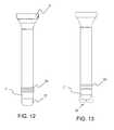
FIG. 12 , thecannula 3 in accordance with the present invention, has a flexible joint 33 with aseal 35 formed of a gel material located at the distal tip 7' of the cannula. Theseal 35 in one aspect is configured to maintain a seal in the absence of inserted instrumentation and the seal, in one aspect, is configured to maintain a seal in the presence of inserted instrumentation. The flexible joint 33 allows theseal 35 and the distal tip 7' to pivot in response to the lateral movement of inserted instrumentation to ensure that aseal 35 is maintained during off-axis movement of the instrumentation. Theseal 35 could be formed of a single piece component with the gel for example shaped as a disc with a slit in the center of the disc. In one aspect, as shown inFIG. 13 , seal 35' is formed of two opposed gel rollers, such that instrumentation would be inserted between the rollers. Thecannula 3 with theseal 35 can also be formed without the flexible joint 33. The elongation and sealing properties of the gel material can enable a seal to be maintained during off-axis movement of inserted instrumentation. The gel material in one aspect is formulated of an SEBS (Styrene Ethylene Butylene Stryrene) copolymer and a mineral oil. - Referring now to
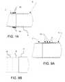
FIG. 14 , the atraumaticelastomeric cannula tip 7 in one aspect is formed with aninternal wire form 19 to provide greater rigidity and column strength as compared to a cannula tip without an internal wire form. Thewire form 19 in one aspect is configured in the shape of a coil spring and a polymer is fused or over-molded over the wire form resulting in acannula tip 7 with an embedded wire form. The wire form in one aspect also comprises a series of wires radially spaced and embedded within the atraumatic elastomeric cannula tip. - Although the present invention has been described in certain specific aspects, many additional modifications and variations would be apparent to those skilled in the art. It is therefore to be understood that the present invention may be practiced otherwise than specifically described, including various changes in the size, shape and materials, without departing from the scope of the present invention as claimed. Thus, embodiments of the present invention should be considered in all respects as illustrative and not restrictive.
- bonded elastomeric tip formed of silicone or polyisoprene to enable the product to be autoclave sterilized and re-used.
- The
cannula 3 with theatraumatic tip 7 in one aspect has a short length over-molded section at its distal tip. The short length over-molded section can provide for an atraumatic elastomeric cannula tip, yet utilize no or minimal column strength or less axial column strength as compared to a longer length over-molded section. The length of the shortened section in one aspect varies from .025" to .250". - In
FIG. 11 , thecannula 3 in one aspect has a flexible elastomeric joint 33 between therigid portion 5 of the cannula and the distal tip 7' of the cannula. The distal tip of the cannula in one aspect is either flexible or rigid. The flexible joint 33 allows the distal tip of the cannula to deflect in response to contact between, for example, body tissue or an instrument thereby preventing potential trauma to the body tissue or potential damage to the instrument. The flexible joint 33 in one aspect has a bellows configuration with a minimal axial length. The minimal axial length of the flexible joint 33 in combination with a rigid or semi-rigiddistal tip 7 in one aspect can provide thecannula 3 with greater column strength as compared to a cannula with an over-molded elastomeric tip. The flexible joint in one aspect is formed from silicone, polyurethane, Kraton® thermoplastic elastomers, C-Flex® thermoplastic elastomers, Versaflex® thermoplastic elastomers, polyisoprene, Santoprene® thermoplastic elastomers, Carbothane® thermoplastic polyurethanes, copolymer/mineral oil gels, or natural rubber. - In
FIG. 12 , in one aspect, thecannula 3 with the flexible joint 33 has aseal 35 formed of a gel material located at the distal tip 7' of the cannula. Theseal 35 in one aspect is configured to maintain a seal in the absence of inserted instrumentation and the seal, in one aspect, is configured to maintain a seal in the presence of inserted instrumentation. The flexible joint 33 allows theseal 35 and the distal tip 7' to pivot in response to the lateral movement of inserted instrumentation to ensure that aseal 35 is maintained during off-axis movement of the instrumentation. Theseal 35 could be formed of a single piece component with the gel for example shaped as a disc with a slit in the center of the disc. In one aspect, as shown inFIG. 13 , seal 35' is formed of two opposed gel rollers, such that instrumentation would be inserted between the rollers. Thecannula 3 with theseal 35 can also be formed without the flexible joint 33. The elongation and sealing properties of the gel material can enable a seal to be maintained during off-axis movement of inserted instrumentation. The gel material in one aspect is formulated of an SEBS (Styrene Ethylene Butylene Stryrene) copolymer and a mineral oil. - Referring now to
FIG. 14 , the atraumaticelastomeric cannula tip 7 in one aspect is formed with aninternal wire form 19 to provide greater rigidity and column strength as compared to a cannula tip without an internal wire form. Thewire form 19 in one aspect is configured in the shape of a coil spring and a polymer is fused or over-molded over the wire form resulting in acannula tip 7 with an embedded wire form. The wire form in one aspect also comprises a series of wires radially spaced and embedded within the atraumatic elastomeric cannula tip. - Accordingly, a trocar cannula with an atraumatic tip is provided. Although the present invention has been described in certain specific aspects, many additional modifications and variations would be apparent to those skilled in the art. It is therefore to be understood that the present invention may be practiced otherwise than specifically described, including various changes in the size, shape and materials, without departing from the scope and spirit of the present invention. Thus, embodiments of the present invention should be considered in all respects as illustrative and not restrictive.
Claims (15)
- A medical access device comprising an articulating laparoscope and a trocar cannula (3) arranged to receive the articulating laparoscope (21), the trocar cannula comprising:an elongate body (5) having a proximal enlarged end comprising a zero seal configured to sealingly engage the articulating laparoscope when the articulating laparoscope is not present and a distal tip end (4) with a lumen extending from the proximal end to the distal end for inserting and removing surgical instruments through the lumen; andan atraumatic tip (7) extending from the distal end (4) of the elongate body (5),characterized in that the trocar cannula (3) further comprises a flexible elastomeric joint (33) between the elongate body (5) and the atraumatic tip (7); the elongate body (5) is formed of a rigid polymer; and the tip (7) is pivotable in use relative to the elongate body (5) to reduce interference with the articulating laparoscope.
- The medical access device of claim 1, wherein the atraumatic tip (7) is formed of a material different than that of the elongate body (5) and the atraumatic tip (7) has a flexural modulus of about 10 x 106 Pa (1,500 psi) and an ultimate elongation of about 400% and the elongate body (5) has a flexural modulus greater than the flexural modulus of the atraumatic tip (7) and an ultimate elongation less than the ultimate elongation of the atraumatic tip (7).
- The medical access device of claim 2, wherein the flexural modulus of the elongate body (5) is 2 x 10⁻⁹ Pa (300,000 psi) and the ultimate elongation of the elongate body is 100%.
- The medical access device of any of the preceding claims, wherein the atraumatic tip (7) has an inner diameter less than an interior diameter of the elongate body (5).
- The medical access device of claim 4, wherein the inner diameter of the atraumatic tip (7) is tapered.
- The medical access device of any of the preceding claims, wherein the inner diameter of the atraumatic tip (7) is chamfered.
- The medical access device of any of the preceding claims, wherein the atraumatic tip (7) is flexible.
- The medical access device of any of claims 1 or 4-6, wherein the atraumatic tip (7) is rigid.
- The medical access device of any of the preceding claims, comprising a second seal (35) formed of a gel material located at the atraumatic tip (7).
- The medical access device of claim 9, wherein the seal (35) comprises two opposed gel rollers.
- The medical access device of any of claims 9-10, wherein the gel material comprises a styrene ethylene butylene styrene copolymer and a mineral oil.
- The medical access device of claim 1, wherein the elongate body (5) and the atraumatic tip (7) are formed of a single material.
- The medical access device of claim 12, wherein the atraumatic tip (7) further comprises axial slots (25) to provide the atraumatic tip (7) with flexibility.
- The medical access device of any preceding claim, wherein the atraumatic tip (7) is integrated with and extends from the flexible joint (33) away from the distal tip end (4) of the elongate body (5).
- The medical access device as claimed in any preceding claim, wherein the trocar cannula further comprises a trocar seal housing (11) removably attached to the enlarged end of the elongate body, the trocar seal housing arranged to sealingly engage with the articulating laparoscope to, in use, prevent loss of gas when the laparoscope is present and provide a zero seal when the articulating laparoscope is not present.
Applications Claiming Priority (2)
| Application Number | Priority Date | Filing Date | Title |
|---|---|---|---|
| US86693906P | 2006-11-22 | 2006-11-22 | |
| EP07854750.2AEP2086430B1 (en) | 2006-11-22 | 2007-11-21 | Trocar cannula with atraumatic tip |
Related Parent Applications (3)
| Application Number | Title | Priority Date | Filing Date |
|---|---|---|---|
| EP07854750.2ADivision-IntoEP2086430B1 (en) | 2006-11-22 | 2007-11-21 | Trocar cannula with atraumatic tip |
| EP07854750.2ADivisionEP2086430B1 (en) | 2006-11-22 | 2007-11-21 | Trocar cannula with atraumatic tip |
| EP07854750.2Division | 2007-11-21 |
Publications (2)
| Publication Number | Publication Date |
|---|---|
| EP2476384A1 EP2476384A1 (en) | 2012-07-18 |
| EP2476384B1true EP2476384B1 (en) | 2015-11-04 |
Family
ID=39267850
Family Applications (2)
| Application Number | Title | Priority Date | Filing Date |
|---|---|---|---|
| EP12164164.1AActiveEP2476384B1 (en) | 2006-11-22 | 2007-11-21 | Trocar cannula with atraumatic tip |
| EP07854750.2AActiveEP2086430B1 (en) | 2006-11-22 | 2007-11-21 | Trocar cannula with atraumatic tip |
Family Applications After (1)
| Application Number | Title | Priority Date | Filing Date |
|---|---|---|---|
| EP07854750.2AActiveEP2086430B1 (en) | 2006-11-22 | 2007-11-21 | Trocar cannula with atraumatic tip |
Country Status (3)
| Country | Link |
|---|---|
| US (2) | US8945058B2 (en) |
| EP (2) | EP2476384B1 (en) |
| WO (1) | WO2008064344A2 (en) |
Families Citing this family (53)
| Publication number | Priority date | Publication date | Assignee | Title |
|---|---|---|---|---|
| CA2631274A1 (en)* | 2007-05-18 | 2008-11-18 | Tyco Healthcare Group Lp | Flexible cannula with associated seal |
| US9474544B2 (en)* | 2010-07-06 | 2016-10-25 | Pivot Medical, Inc. | Method and apparatus for accessing the interior of a hip joint, including the provision and use of a novel inflow access cannula |
| US20130102967A1 (en)* | 2011-10-21 | 2013-04-25 | Synergetics, Inc. | Magnetic Trocar System |
| US9757536B2 (en) | 2012-07-17 | 2017-09-12 | Novartis Ag | Soft tip cannula |
| US10342699B2 (en) | 2012-08-03 | 2019-07-09 | J.D. Franco & Co., Llc | Systems and methods for treating eye diseases |
| CA3206182A1 (en) | 2012-11-21 | 2014-05-30 | Amgen Inc. | Drug delivery device including insertion member and reservoir |
| CA2894544A1 (en) | 2012-12-27 | 2014-07-03 | Covidien Lp | Two-shot molded optical obturator |
| US20140275768A1 (en)* | 2013-03-13 | 2014-09-18 | Covidien Lp | Thoracic Scope With Skirt And Gap |
| WO2014158613A1 (en) | 2013-03-14 | 2014-10-02 | Saphena Medical, Inc. | Unitary endoscopic vessel harvesting devices |
| US9814481B2 (en) | 2013-03-14 | 2017-11-14 | Saphena Medical, Inc. | Unitary endoscopic vessel harvesting devices |
| US9622750B2 (en)* | 2013-08-21 | 2017-04-18 | Crh Medical Corporation | Elastic band ligation device with locking mechanism and method for treatment of hemorrhoids |
| US9101360B2 (en)* | 2013-08-21 | 2015-08-11 | Crh Medical Corporation | Elastic band ligation device with integrated obturator and method for treatment of hemorrhoids |
| US20150057680A1 (en)* | 2013-08-21 | 2015-02-26 | Crh Medical Corporation | Elastic band ligation device with anti-pinch feature and method for treatment of hemorrhoids |
| US9936952B2 (en)* | 2014-02-03 | 2018-04-10 | Covidien Lp | Introducer assembly for a surgical fastener applying apparatus |
| US9687413B2 (en) | 2014-02-18 | 2017-06-27 | Covidien Lp | Compression garment inflation |
| WO2016007650A1 (en)* | 2014-07-08 | 2016-01-14 | Applied Medical Resources Corporation | Highly responsive instrument seal |
| DK3341070T3 (en)* | 2014-08-27 | 2020-03-16 | Neuronano Ab | DEVICE FOR IMPLANTING A MEDICAL DEVICE IN NEURAL Tissue |
| WO2016164824A1 (en) | 2015-04-09 | 2016-10-13 | Auris Surgical Robotics, Inc. | Surgical system with configurable rail-mounted mechanical arms |
| US9943328B2 (en) | 2015-04-28 | 2018-04-17 | Saphena Medical, Inc. | Unitary endoscopic vessel harvesting devices with an elastic force |
| JP7166761B2 (en) | 2015-06-17 | 2022-11-08 | サフィナ・メディカル・インコーポレイテッド | single endoscope angiography device |
| EP3310277B1 (en)* | 2015-06-17 | 2021-05-26 | Saphena Medical, Inc. | Unitary endoscopic vessel harvesting devices |
| US20160374854A1 (en)* | 2015-06-26 | 2016-12-29 | Art, Ltd. | Surgical apparatus and method of making the same |
| DE102016101462B4 (en)* | 2016-01-27 | 2019-01-17 | Karl Storz Se & Co. Kg | Trocar sleeve, trocar system and method for producing a trocar sleeve |
| IL300148B2 (en)* | 2016-01-29 | 2024-01-01 | Abiomed Inc | Percutaneous pump system and cannula for a percutaneous pump |
| US10485582B2 (en)* | 2016-07-22 | 2019-11-26 | Intuitive Surgical Operations, Inc. | Cannulas having body wall retention features, and related systems and methods |
| AU2018213053A1 (en)* | 2017-01-25 | 2019-08-29 | J.D. Franco & Co., Llc | Blood vessel access and closure devices and related methods of use |
| US10751087B2 (en)* | 2017-09-29 | 2020-08-25 | Ethicon Llc | Radial biasing devices for trocar assembly |
| US10779929B2 (en) | 2017-10-06 | 2020-09-22 | J.D. Franco & Co., Llc | Treating eye diseases by deploying a stent |
| US10758254B2 (en) | 2017-12-15 | 2020-09-01 | J.D. Franco & Co., Llc | Medical systems, devices, and related methods |
| KR102264368B1 (en) | 2018-01-17 | 2021-06-17 | 아우리스 헬스, 인코포레이티드 | Surgical platform with adjustable arm support |
| WO2020005370A1 (en)* | 2018-06-27 | 2020-01-02 | Auris Health, Inc. | Systems and techniques for providing multiple perspectives during medical procedures |
| WO2020054331A1 (en)* | 2018-09-12 | 2020-03-19 | テルモ株式会社 | Catheter assembly |
| JP7427654B2 (en) | 2018-09-17 | 2024-02-05 | オーリス ヘルス インコーポレイテッド | Systems and methods for performing associated medical procedures |
| CN112804959B (en) | 2018-09-28 | 2025-01-28 | 奥瑞斯健康公司 | Robotic systems and methods for accompanying endoscopic and percutaneous medical procedures |
| US11254009B2 (en) | 2018-12-20 | 2022-02-22 | Auris Health, Inc. | Systems and methods for robotic arm alignment and docking |
| US12096958B2 (en)* | 2018-12-27 | 2024-09-24 | Conmed Corporation | Soft-thread cannula and cannula seal assembly |
| US10765843B2 (en) | 2018-12-31 | 2020-09-08 | J.D. Franco & Co., Llc | Intravascular devices, systems, and methods to address eye disorders |
| US11857277B2 (en) | 2019-02-08 | 2024-01-02 | Auris Health, Inc. | Robotically controlled clot manipulation and removal |
| WO2020206266A1 (en) | 2019-04-05 | 2020-10-08 | Saphena Medical, Inc. | Unitary device for vessel harvesting and method of using same |
| EP3952779A4 (en) | 2019-04-08 | 2023-01-18 | Auris Health, Inc. | SYSTEMS, PROCESSES AND WORKFLOW FOR CONCURRENT PROCEEDINGS |
| US12023119B2 (en) | 2019-06-26 | 2024-07-02 | Auris Health, Inc. | Systems and methods for robotic arm alignment and docking |
| WO2021007327A1 (en)* | 2019-07-08 | 2021-01-14 | Cannuflow, Inc. | Arthroscopic cannula and suture management system |
| CN114375182A (en) | 2019-09-10 | 2022-04-19 | 奥瑞斯健康公司 | System and method for kinematic optimization using shared robot degrees of freedom |
| US10959792B1 (en) | 2019-09-26 | 2021-03-30 | Auris Health, Inc. | Systems and methods for collision detection and avoidance |
| WO2021059100A1 (en) | 2019-09-26 | 2021-04-01 | Auris Health, Inc. | Systems and methods for collision avoidance using object models |
| US11786271B2 (en) | 2019-12-29 | 2023-10-17 | Biosense Webster (Israel) Ltd. | Trocar with modular obturator head |
| US11819242B2 (en) | 2019-12-29 | 2023-11-21 | Biosense Webster (Israel) Ltd. | Navigated trocar with internal camera |
| US12370002B2 (en) | 2020-03-30 | 2025-07-29 | Auris Health, Inc. | Workspace optimization for robotic surgery |
| USD958360S1 (en)* | 2020-05-01 | 2022-07-19 | Cilag Gmbh International | Cannula assembly |
| US20210378703A1 (en)* | 2020-06-04 | 2021-12-09 | Covidien Lp | Surgical access device including adjustable cannula portion |
| CN115802975A (en) | 2020-06-29 | 2023-03-14 | 奥瑞斯健康公司 | System and method for detecting contact between a connecting rod and an external object |
| CN115734765A (en) | 2020-06-30 | 2023-03-03 | 奥瑞斯健康公司 | Robotic medical system with crash proximity indicator |
| US11357586B2 (en) | 2020-06-30 | 2022-06-14 | Auris Health, Inc. | Systems and methods for saturated robotic movement |
Citations (4)
| Publication number | Priority date | Publication date | Assignee | Title |
|---|---|---|---|---|
| EP0192576A1 (en)* | 1985-02-22 | 1986-08-27 | Medicorp Research Laboratories Corporation | Steerable endovascular probe |
| US20030004528A1 (en)* | 2000-12-12 | 2003-01-02 | Olympus Optical Co., Ltd. | Trocar and trocar system |
| EP1557130A1 (en)* | 2004-01-20 | 2005-07-27 | Ethicon Endo-Surgery, Inc. | Medical device for providing access |
| US7879009B1 (en)* | 2010-01-29 | 2011-02-01 | Warsaw Orthopedic, Inc. | Variable opening delivery system for intervertebral disc therapies |
Family Cites Families (92)
| Publication number | Priority date | Publication date | Assignee | Title |
|---|---|---|---|---|
| US3959429A (en) | 1975-02-03 | 1976-05-25 | International Paper Company | Method of making a retention catheter and molding a tip thereon |
| US4385635A (en) | 1980-04-25 | 1983-05-31 | Ruiz Oscar F | Angiographic catheter with soft tip end |
| US4402684A (en) | 1981-09-16 | 1983-09-06 | The Kendall Company | Cannula with soft tip |
| US4402384A (en)* | 1981-11-04 | 1983-09-06 | Hoover Universal, Inc. | Sound barrier system |
| US4563181A (en) | 1983-02-18 | 1986-01-07 | Mallinckrodt, Inc. | Fused flexible tip catheter |
| US4531943A (en) | 1983-08-08 | 1985-07-30 | Angiomedics Corporation | Catheter with soft deformable tip |
| US4801297A (en) | 1984-06-01 | 1989-01-31 | Edward Weck Incorporated | Catheter having slit tip |
| US4776844A (en) | 1986-05-02 | 1988-10-11 | Olympus Optical Co., Ltd. | Medical tube |
| US4886506A (en) | 1986-12-23 | 1989-12-12 | Baxter Travenol Laboratories, Inc. | Soft tip catheter |
| US4795426A (en)* | 1987-04-02 | 1989-01-03 | Solutech, Inc. | Catheter introducing device and method of placing catheter |
| US4863442A (en) | 1987-08-14 | 1989-09-05 | C. R. Bard, Inc. | Soft tip catheter |
| US5078702A (en) | 1988-03-25 | 1992-01-07 | Baxter International Inc. | Soft tip catheters |
| US4950257A (en) | 1988-09-15 | 1990-08-21 | Mallinckrodt, Inc. | Catheter introducer with flexible tip |
| US5017259A (en) | 1988-10-13 | 1991-05-21 | Terumo Kabushiki Kaisha | Preparation of catheter including bonding and then thermoforming |
| US4875468A (en) | 1988-12-23 | 1989-10-24 | Welch Allyn, Inc. | Elastomer-ePTFE biopsy channel |
| US5045072A (en) | 1989-06-13 | 1991-09-03 | Cordis Corporation | Catheter having highly radiopaque, flexible tip |
| US5049138A (en)* | 1989-11-13 | 1991-09-17 | Boston Scientific Corporation | Catheter with dissolvable tip |
| US5179934A (en) | 1990-02-20 | 1993-01-19 | Olympus Optical Co., Ltd. | Endoscope |
| US5295994A (en) | 1991-11-15 | 1994-03-22 | Bonutti Peter M | Active cannulas |
| US5112312A (en)* | 1991-03-14 | 1992-05-12 | Luther Medical Products, Inc. | Vascular/venous access device and method of utilizing and forming the same |
| US5120317A (en) | 1991-03-14 | 1992-06-09 | Luther Medical Products, Inc. | Vascular/venous access device and method of utilizing and forming the same |
| US5234416A (en) | 1991-06-06 | 1993-08-10 | Advanced Cardiovascular Systems, Inc. | Intravascular catheter with a nontraumatic distal tip |
| US5221270A (en)* | 1991-06-28 | 1993-06-22 | Cook Incorporated | Soft tip guiding catheter |
| US5769830A (en) | 1991-06-28 | 1998-06-23 | Cook Incorporated | Soft tip guiding catheter |
| US5240537A (en) | 1991-07-01 | 1993-08-31 | Namic U.S.A. Corporation | Method for manufacturing a soft tip catheter |
| US5318032A (en) | 1992-02-05 | 1994-06-07 | Devices For Vascular Intervention | Guiding catheter having soft tip |
| US5257973A (en)* | 1992-02-05 | 1993-11-02 | Raul Villasuso | Sealing sleeve and method for laparoscopy |
| US5584821A (en) | 1992-06-02 | 1996-12-17 | E-Z-Em, Inc. | Soft tip catheter |
| JP3191981B2 (en) | 1992-06-12 | 2001-07-23 | オリンパス光学工業株式会社 | Endoscope insertion guide tube |
| US5399164A (en) | 1992-11-02 | 1995-03-21 | Catheter Imaging Systems | Catheter having a multiple durometer |
| US6338730B1 (en) | 1993-02-04 | 2002-01-15 | Peter M. Bonutti | Method of using expandable cannula |
| US5450842A (en) | 1993-02-19 | 1995-09-19 | United States Surgical Corporation | Endoscopic surgical retractor |
| US5257980A (en) | 1993-04-05 | 1993-11-02 | Minimed Technologies, Ltd. | Subcutaneous injection set with crimp-free soft cannula |
| US5417665A (en) | 1993-10-19 | 1995-05-23 | Cordis Corporation | Intravascular cannula |
| JPH07148171A (en) | 1993-11-26 | 1995-06-13 | Olympus Optical Co Ltd | Tube-shaped inserting instrument |
| JPH07184846A (en) | 1993-12-27 | 1995-07-25 | Olympus Optical Co Ltd | Trocar apparatus |
| DE4401237C2 (en) | 1994-01-18 | 1997-06-05 | Ruesch Willy Ag | Trocar device |
| US5911715A (en) | 1994-02-14 | 1999-06-15 | Scimed Life Systems, Inc. | Guide catheter having selected flexural modulus segments |
| US5533985A (en) | 1994-04-20 | 1996-07-09 | Wang; James C. | Tubing |
| US5509910A (en) | 1994-05-02 | 1996-04-23 | Medtronic, Inc. | Method of soft tip attachment for thin walled catheters |
| US5599319A (en) | 1994-09-01 | 1997-02-04 | Cordis Corporation | Soft flexible catheter tip for use in angiography |
| JPH0884846A (en)* | 1994-09-14 | 1996-04-02 | Akiyoshi Kurihara | Pachinko ball feeding-up device |
| AU4763296A (en) | 1995-02-03 | 1996-08-21 | Inbae Yoon | Cannula with distal end valve |
| DE19534112A1 (en)* | 1995-09-14 | 1997-03-20 | Wolf Gmbh Richard | Endoscopic instrument with steerable distal end |
| US5701905A (en) | 1995-11-13 | 1997-12-30 | Localmed, Inc. | Guide catheter with sensing element |
| US6015403A (en) | 1996-02-26 | 2000-01-18 | Alcon Laboratories, Inc. | Ophthalmic surgery probe with soft tip |
| DE69735146T2 (en)* | 1996-05-09 | 2006-09-28 | Olympus Corporation | Surgical tool for holding a cavity |
| US5820606A (en)* | 1996-06-11 | 1998-10-13 | Origin Medsystems, Inc. | Reusable cannula with disposable seal |
| US6273869B1 (en) | 1996-06-13 | 2001-08-14 | Vincent L. Vaillancourt | Valve connector |
| US5762637A (en) | 1996-08-27 | 1998-06-09 | Scimed Life Systems, Inc. | Insert molded catheter tip |
| US5935107A (en)* | 1996-10-07 | 1999-08-10 | Applied Medical Resources Corporation | Apparatus and method for surgically accessing a body cavity |
| US6013024A (en)* | 1997-01-20 | 2000-01-11 | Suzuki Motor Corporation | Hybrid operation system |
| US6077258A (en) | 1997-10-03 | 2000-06-20 | Scimed Life Systems, Inc. | Braided angiography catheter having full length radiopacity and controlled flexibility |
| US6007478A (en)* | 1997-11-13 | 1999-12-28 | Impella Cardiotechnik Aktiengesellschaft | Cannula having constant wall thickness with increasing distal flexibility and method of making |
| US6533770B1 (en) | 1998-01-21 | 2003-03-18 | Heartport, Inc. | Cannula and method of manufacture and use |
| US6245053B1 (en) | 1998-11-09 | 2001-06-12 | Medtronic, Inc. | Soft tip guiding catheter and method of fabrication |
| US6413228B1 (en)* | 1998-12-28 | 2002-07-02 | Pro Duct Health, Inc. | Devices, methods and systems for collecting material from a breast duct |
| US6171282B1 (en) | 1999-07-23 | 2001-01-09 | Edgar K. Ragsdale | Soft cannula and methods for use |
| US6893427B1 (en) | 2000-03-23 | 2005-05-17 | Vascon, Llc | Catheter with thermoresponsive distal tip portion |
| US6491670B1 (en) | 2000-04-04 | 2002-12-10 | Duke University | Miniaturized surgical instruments especially useful for the opthalmologic surgical procedures and methods of making the same |
| GB2370506B (en) | 2000-10-04 | 2005-02-16 | Biocompatibles Ltd | Catheter tip |
| US6800076B2 (en) | 2000-10-18 | 2004-10-05 | Retinalabs, Inc. | Soft tip cannula and methods for use thereof |
| DE10117286A1 (en) | 2001-04-06 | 2002-10-17 | Disetronic Licensing Ag | Soft cannula |
| US6989003B2 (en)* | 2001-08-31 | 2006-01-24 | Conmed Corporation | Obturator and cannula for a trocar adapted for ease of insertion and removal |
| JP3639561B2 (en) | 2002-04-08 | 2005-04-20 | オリンパス株式会社 | Endoscope hood |
| WO2003088854A1 (en) | 2002-04-15 | 2003-10-30 | Tyco Healthcare Group, Lp | Instrument introducer |
| US6866655B2 (en) | 2002-04-23 | 2005-03-15 | Scimed Life Systems, Inc. | Medical device with atraumatic tip |
| WO2003096879A2 (en)* | 2002-05-16 | 2003-11-27 | Applied Medical Resources Corporation | Cone tip obturator |
| US7115134B2 (en) | 2002-07-22 | 2006-10-03 | Chambers Technology, Llc. | Catheter with flexible tip and shape retention |
| US6723073B2 (en)* | 2002-09-06 | 2004-04-20 | Cardiac Pacemakers, Inc. | Hemostasis valve for use with a left ventricular pacing lead |
| US7083626B2 (en)* | 2002-10-04 | 2006-08-01 | Applied Medical Resources Corporation | Surgical access device with pendent valve |
| US20050165366A1 (en) | 2004-01-28 | 2005-07-28 | Brustad John R. | Medical tubing having variable characteristics and method of making same |
| US20050256452A1 (en) | 2002-11-15 | 2005-11-17 | Demarchi Thomas | Steerable vascular sheath |
| US7390317B2 (en)* | 2002-12-02 | 2008-06-24 | Applied Medical Resources Corporation | Universal access seal |
| US7037290B2 (en)* | 2002-12-16 | 2006-05-02 | Medtronic, Inc. | Multi-lumen steerable catheter |
| US7980520B2 (en)* | 2003-03-13 | 2011-07-19 | Scott Taylor | Hanging apparatus assembly and method |
| CA2522617C (en)* | 2003-04-25 | 2012-04-17 | Tyco Healthcare Group Lp | Surgical access apparatus |
| US8684967B2 (en) | 2003-07-15 | 2014-04-01 | Medtronic, Inc. | Kink resistant cannula having buckle resistant apertures |
| US7184846B2 (en)* | 2003-10-31 | 2007-02-27 | Cornell Research Foundation, Inc. | Systems and methods for providing optimal light-CO2 combinations for plant production |
| US7494472B2 (en) | 2003-12-23 | 2009-02-24 | Windy Hill Medical, Inc. | Ductal lavage catheter having an off-axis tip |
| US7445596B2 (en) | 2004-01-29 | 2008-11-04 | Cannuflow, Inc. | Atraumatic arthroscopic instrument sheath |
| US8007477B2 (en) | 2004-03-22 | 2011-08-30 | Applied Medical Resources Corporation | Surgical access port and method of using same |
| US8292853B2 (en) | 2004-03-24 | 2012-10-23 | Applied Medical Resources Corporation | Self-sealing cannula having integrated seals |
| GB2425483A (en) | 2005-04-29 | 2006-11-01 | Hans-Ulrich Laasch | A single step trocar based insertion device |
| US7591802B2 (en)* | 2005-04-29 | 2009-09-22 | Applied Medical Resources Corporation | Seal housing having anti-inversion features |
| EP1933733A2 (en)* | 2005-10-14 | 2008-06-25 | Applied Medical Resources Corporation | Surgical access port |
| US20080249475A1 (en)* | 2006-02-22 | 2008-10-09 | Applied Medical Resources Corporation | Trocar seal |
| US8066673B2 (en)* | 2006-03-21 | 2011-11-29 | Applied Medical Resources Corporation | Cannula stabilization seal |
| US20070260273A1 (en) | 2006-05-08 | 2007-11-08 | Ethicon Endo-Surgery, Inc. | Endoscopic Translumenal Surgical Systems |
| US8685034B2 (en)* | 2006-08-10 | 2014-04-01 | Stryker Trauma Gmbh | Distal targeting device |
| EP2851020B1 (en)* | 2008-01-25 | 2016-01-20 | Applied Medical Resources Corporation | Insufflating access system |
| AU2009222028A1 (en)* | 2008-03-03 | 2009-09-11 | Applied Medical Resources Corporation | Balloon trocar advanced fixation |
- 2007
- 2007-11-21EPEP12164164.1Apatent/EP2476384B1/enactiveActive
- 2007-11-21USUS12/445,263patent/US8945058B2/enactiveActive
- 2007-11-21EPEP07854750.2Apatent/EP2086430B1/enactiveActive
- 2007-11-21WOPCT/US2007/085444patent/WO2008064344A2/enactiveApplication Filing
- 2015
- 2015-01-30USUS14/610,292patent/US10485578B2/enactiveActive
Patent Citations (4)
| Publication number | Priority date | Publication date | Assignee | Title |
|---|---|---|---|---|
| EP0192576A1 (en)* | 1985-02-22 | 1986-08-27 | Medicorp Research Laboratories Corporation | Steerable endovascular probe |
| US20030004528A1 (en)* | 2000-12-12 | 2003-01-02 | Olympus Optical Co., Ltd. | Trocar and trocar system |
| EP1557130A1 (en)* | 2004-01-20 | 2005-07-27 | Ethicon Endo-Surgery, Inc. | Medical device for providing access |
| US7879009B1 (en)* | 2010-01-29 | 2011-02-01 | Warsaw Orthopedic, Inc. | Variable opening delivery system for intervertebral disc therapies |
Also Published As
| Publication number | Publication date |
|---|---|
| EP2086430B1 (en) | 2015-01-07 |
| US20100100045A1 (en) | 2010-04-22 |
| WO2008064344A3 (en) | 2009-04-23 |
| US10485578B2 (en) | 2019-11-26 |
| EP2476384A1 (en) | 2012-07-18 |
| WO2008064344A2 (en) | 2008-05-29 |
| EP2086430A2 (en) | 2009-08-12 |
| US20150141938A1 (en) | 2015-05-21 |
| US8945058B2 (en) | 2015-02-03 |
Similar Documents
| Publication | Publication Date | Title |
|---|---|---|
| EP2476384B1 (en) | Trocar cannula with atraumatic tip | |
| EP2277464B1 (en) | Surgical port and frangible introducer assembly | |
| US9119664B2 (en) | Integral foam port | |
| US9421032B2 (en) | Seal port with blood collector | |
| EP2324785B1 (en) | Foam port device having closed-end lumens | |
| US5104383A (en) | Trocar adapter seal and method of use | |
| EP2374422B1 (en) | Surgical access assembly including sleeve and port | |
| EP2229897B1 (en) | Surgical portal apparatus including movable housing | |
| US20130225932A1 (en) | Multi-portion wound protector | |
| EP2098182A2 (en) | Single port device with multi-lumen cap | |
| US20080108871A1 (en) | Vacuum stabilized overtube for endoscopic surgery | |
| KR20090086546A (en) | Trocar Seal with Shrink-Induced Hinge | |
| EP0424002B1 (en) | Cannula with sealing element | |
| EP2204128A1 (en) | Dual seal with bellows | |
| KR20100109481A (en) | Access device | |
| JP2010259805A (en) | Ring and seal for trocar | |
| WO2008095270A1 (en) | Laparoscopic trocar with flexible endoscopic system | |
| AU2014203162A1 (en) | Foam port device having closed-end lumens |
Legal Events
| Date | Code | Title | Description |
|---|---|---|---|
| PUAI | Public reference made under article 153(3) epc to a published international application that has entered the european phase | Free format text:ORIGINAL CODE: 0009012 | |
| 17P | Request for examination filed | Effective date:20120413 | |
| AC | Divisional application: reference to earlier application | Ref document number:2086430 Country of ref document:EP Kind code of ref document:P | |
| AK | Designated contracting states | Kind code of ref document:A1 Designated state(s):AT BE BG CH CY CZ DE DK EE ES FI FR GB GR HU IE IS IT LI LT LU LV MC MT NL PL PT RO SE SI SK TR | |
| 17Q | First examination report despatched | Effective date:20121030 | |
| GRAP | Despatch of communication of intention to grant a patent | Free format text:ORIGINAL CODE: EPIDOSNIGR1 | |
| INTG | Intention to grant announced | Effective date:20150617 | |
| GRAS | Grant fee paid | Free format text:ORIGINAL CODE: EPIDOSNIGR3 | |
| GRAA | (expected) grant | Free format text:ORIGINAL CODE: 0009210 | |
| AC | Divisional application: reference to earlier application | Ref document number:2086430 Country of ref document:EP Kind code of ref document:P | |
| AK | Designated contracting states | Kind code of ref document:B1 Designated state(s):AT BE BG CH CY CZ DE DK EE ES FI FR GB GR HU IE IS IT LI LT LU LV MC MT NL PL PT RO SE SI SK TR | |
| REG | Reference to a national code | Ref country code:GB Ref legal event code:FG4D | |
| REG | Reference to a national code | Ref country code:CH Ref legal event code:EP | |
| REG | Reference to a national code | Ref country code:AT Ref legal event code:REF Ref document number:758634 Country of ref document:AT Kind code of ref document:T Effective date:20151115 | |
| REG | Reference to a national code | Ref country code:FR Ref legal event code:PLFP Year of fee payment:9 | |
| REG | Reference to a national code | Ref country code:IE Ref legal event code:FG4D | |
| REG | Reference to a national code | Ref country code:DE Ref legal event code:R096 Ref document number:602007043828 Country of ref document:DE | |
| REG | Reference to a national code | Ref country code:NL Ref legal event code:MP Effective date:20151104 | |
| REG | Reference to a national code | Ref country code:LT Ref legal event code:MG4D | |
| REG | Reference to a national code | Ref country code:AT Ref legal event code:MK05 Ref document number:758634 Country of ref document:AT Kind code of ref document:T Effective date:20151104 | |
| PG25 | Lapsed in a contracting state [announced via postgrant information from national office to epo] | Ref country code:ES Free format text:LAPSE BECAUSE OF FAILURE TO SUBMIT A TRANSLATION OF THE DESCRIPTION OR TO PAY THE FEE WITHIN THE PRESCRIBED TIME-LIMIT Effective date:20151104 Ref country code:LT Free format text:LAPSE BECAUSE OF FAILURE TO SUBMIT A TRANSLATION OF THE DESCRIPTION OR TO PAY THE FEE WITHIN THE PRESCRIBED TIME-LIMIT Effective date:20151104 Ref country code:IT Free format text:LAPSE BECAUSE OF FAILURE TO SUBMIT A TRANSLATION OF THE DESCRIPTION OR TO PAY THE FEE WITHIN THE PRESCRIBED TIME-LIMIT Effective date:20151104 Ref country code:NL Free format text:LAPSE BECAUSE OF FAILURE TO SUBMIT A TRANSLATION OF THE DESCRIPTION OR TO PAY THE FEE WITHIN THE PRESCRIBED TIME-LIMIT Effective date:20151104 Ref country code:IS Free format text:LAPSE BECAUSE OF FAILURE TO SUBMIT A TRANSLATION OF THE DESCRIPTION OR TO PAY THE FEE WITHIN THE PRESCRIBED TIME-LIMIT Effective date:20160304 | |
| PG25 | Lapsed in a contracting state [announced via postgrant information from national office to epo] | Ref country code:LV Free format text:LAPSE BECAUSE OF FAILURE TO SUBMIT A TRANSLATION OF THE DESCRIPTION OR TO PAY THE FEE WITHIN THE PRESCRIBED TIME-LIMIT Effective date:20151104 Ref country code:AT Free format text:LAPSE BECAUSE OF FAILURE TO SUBMIT A TRANSLATION OF THE DESCRIPTION OR TO PAY THE FEE WITHIN THE PRESCRIBED TIME-LIMIT Effective date:20151104 Ref country code:PL Free format text:LAPSE BECAUSE OF FAILURE TO SUBMIT A TRANSLATION OF THE DESCRIPTION OR TO PAY THE FEE WITHIN THE PRESCRIBED TIME-LIMIT Effective date:20151104 Ref country code:BE Free format text:LAPSE BECAUSE OF NON-PAYMENT OF DUE FEES Effective date:20151130 Ref country code:FI Free format text:LAPSE BECAUSE OF FAILURE TO SUBMIT A TRANSLATION OF THE DESCRIPTION OR TO PAY THE FEE WITHIN THE PRESCRIBED TIME-LIMIT Effective date:20151104 Ref country code:GR Free format text:LAPSE BECAUSE OF FAILURE TO SUBMIT A TRANSLATION OF THE DESCRIPTION OR TO PAY THE FEE WITHIN THE PRESCRIBED TIME-LIMIT Effective date:20160205 Ref country code:SE Free format text:LAPSE BECAUSE OF FAILURE TO SUBMIT A TRANSLATION OF THE DESCRIPTION OR TO PAY THE FEE WITHIN THE PRESCRIBED TIME-LIMIT Effective date:20151104 Ref country code:PT Free format text:LAPSE BECAUSE OF FAILURE TO SUBMIT A TRANSLATION OF THE DESCRIPTION OR TO PAY THE FEE WITHIN THE PRESCRIBED TIME-LIMIT Effective date:20160304 | |
| REG | Reference to a national code | Ref country code:CH Ref legal event code:PL | |
| PG25 | Lapsed in a contracting state [announced via postgrant information from national office to epo] | Ref country code:CZ Free format text:LAPSE BECAUSE OF FAILURE TO SUBMIT A TRANSLATION OF THE DESCRIPTION OR TO PAY THE FEE WITHIN THE PRESCRIBED TIME-LIMIT Effective date:20151104 Ref country code:CH Free format text:LAPSE BECAUSE OF NON-PAYMENT OF DUE FEES Effective date:20151130 Ref country code:LI Free format text:LAPSE BECAUSE OF NON-PAYMENT OF DUE FEES Effective date:20151130 | |
| REG | Reference to a national code | Ref country code:DE Ref legal event code:R097 Ref document number:602007043828 Country of ref document:DE | |
| REG | Reference to a national code | Ref country code:IE Ref legal event code:MM4A | |
| PG25 | Lapsed in a contracting state [announced via postgrant information from national office to epo] | Ref country code:RO Free format text:LAPSE BECAUSE OF FAILURE TO SUBMIT A TRANSLATION OF THE DESCRIPTION OR TO PAY THE FEE WITHIN THE PRESCRIBED TIME-LIMIT Effective date:20151104 Ref country code:DK Free format text:LAPSE BECAUSE OF FAILURE TO SUBMIT A TRANSLATION OF THE DESCRIPTION OR TO PAY THE FEE WITHIN THE PRESCRIBED TIME-LIMIT Effective date:20151104 Ref country code:EE Free format text:LAPSE BECAUSE OF FAILURE TO SUBMIT A TRANSLATION OF THE DESCRIPTION OR TO PAY THE FEE WITHIN THE PRESCRIBED TIME-LIMIT Effective date:20151104 Ref country code:SK Free format text:LAPSE BECAUSE OF FAILURE TO SUBMIT A TRANSLATION OF THE DESCRIPTION OR TO PAY THE FEE WITHIN THE PRESCRIBED TIME-LIMIT Effective date:20151104 | |
| PLBE | No opposition filed within time limit | Free format text:ORIGINAL CODE: 0009261 | |
| STAA | Information on the status of an ep patent application or granted ep patent | Free format text:STATUS: NO OPPOSITION FILED WITHIN TIME LIMIT | |
| PG25 | Lapsed in a contracting state [announced via postgrant information from national office to epo] | Ref country code:MC Free format text:LAPSE BECAUSE OF FAILURE TO SUBMIT A TRANSLATION OF THE DESCRIPTION OR TO PAY THE FEE WITHIN THE PRESCRIBED TIME-LIMIT Effective date:20151104 | |
| 26N | No opposition filed | Effective date:20160805 | |
| PG25 | Lapsed in a contracting state [announced via postgrant information from national office to epo] | Ref country code:IE Free format text:LAPSE BECAUSE OF NON-PAYMENT OF DUE FEES Effective date:20151121 | |
| REG | Reference to a national code | Ref country code:FR Ref legal event code:PLFP Year of fee payment:10 | |
| PG25 | Lapsed in a contracting state [announced via postgrant information from national office to epo] | Ref country code:SI Free format text:LAPSE BECAUSE OF FAILURE TO SUBMIT A TRANSLATION OF THE DESCRIPTION OR TO PAY THE FEE WITHIN THE PRESCRIBED TIME-LIMIT Effective date:20151104 | |
| PG25 | Lapsed in a contracting state [announced via postgrant information from national office to epo] | Ref country code:BE Free format text:LAPSE BECAUSE OF FAILURE TO SUBMIT A TRANSLATION OF THE DESCRIPTION OR TO PAY THE FEE WITHIN THE PRESCRIBED TIME-LIMIT Effective date:20151104 | |
| PG25 | Lapsed in a contracting state [announced via postgrant information from national office to epo] | Ref country code:HU Free format text:LAPSE BECAUSE OF FAILURE TO SUBMIT A TRANSLATION OF THE DESCRIPTION OR TO PAY THE FEE WITHIN THE PRESCRIBED TIME-LIMIT; INVALID AB INITIO Effective date:20071121 Ref country code:BG Free format text:LAPSE BECAUSE OF FAILURE TO SUBMIT A TRANSLATION OF THE DESCRIPTION OR TO PAY THE FEE WITHIN THE PRESCRIBED TIME-LIMIT Effective date:20151104 | |
| PG25 | Lapsed in a contracting state [announced via postgrant information from national office to epo] | Ref country code:CY Free format text:LAPSE BECAUSE OF FAILURE TO SUBMIT A TRANSLATION OF THE DESCRIPTION OR TO PAY THE FEE WITHIN THE PRESCRIBED TIME-LIMIT Effective date:20151104 | |
| PG25 | Lapsed in a contracting state [announced via postgrant information from national office to epo] | Ref country code:TR Free format text:LAPSE BECAUSE OF FAILURE TO SUBMIT A TRANSLATION OF THE DESCRIPTION OR TO PAY THE FEE WITHIN THE PRESCRIBED TIME-LIMIT Effective date:20151104 Ref country code:MT Free format text:LAPSE BECAUSE OF FAILURE TO SUBMIT A TRANSLATION OF THE DESCRIPTION OR TO PAY THE FEE WITHIN THE PRESCRIBED TIME-LIMIT Effective date:20151104 | |
| REG | Reference to a national code | Ref country code:FR Ref legal event code:PLFP Year of fee payment:11 | |
| PG25 | Lapsed in a contracting state [announced via postgrant information from national office to epo] | Ref country code:LU Free format text:LAPSE BECAUSE OF NON-PAYMENT OF DUE FEES Effective date:20151121 | |
| P01 | Opt-out of the competence of the unified patent court (upc) registered | Effective date:20230521 | |
| PGFP | Annual fee paid to national office [announced via postgrant information from national office to epo] | Ref country code:DE Payment date:20241127 Year of fee payment:18 | |
| PGFP | Annual fee paid to national office [announced via postgrant information from national office to epo] | Ref country code:GB Payment date:20241127 Year of fee payment:18 | |
| PGFP | Annual fee paid to national office [announced via postgrant information from national office to epo] | Ref country code:FR Payment date:20241128 Year of fee payment:18 |