EP2476108B1 - Alert for real-time risk of theft or loss - Google Patents
Alert for real-time risk of theft or lossDownload PDFInfo
- Publication number
- EP2476108B1 EP2476108B1EP10814852.9AEP10814852AEP2476108B1EP 2476108 B1EP2476108 B1EP 2476108B1EP 10814852 AEP10814852 AEP 10814852AEP 2476108 B1EP2476108 B1EP 2476108B1
- Authority
- EP
- European Patent Office
- Prior art keywords
- theft
- monitored
- devices
- electronic devices
- electronic device
- Prior art date
- Legal status (The legal status is an assumption and is not a legal conclusion. Google has not performed a legal analysis and makes no representation as to the accuracy of the status listed.)
- Active
Links
- 238000000034methodMethods0.000claimsdescription37
- 238000012544monitoring processMethods0.000claimsdescription16
- 238000004891communicationMethods0.000claimsdescription13
- 230000004044responseEffects0.000claimsdescription4
- 230000005540biological transmissionEffects0.000claims1
- 230000000007visual effectEffects0.000claims1
- 238000000926separation methodMethods0.000description11
- 230000009471actionEffects0.000description10
- 238000010586diagramMethods0.000description9
- 230000008569processEffects0.000description9
- 238000012552reviewMethods0.000description8
- 230000001413cellular effectEffects0.000description4
- 230000033001locomotionEffects0.000description4
- 230000002265preventionEffects0.000description4
- 230000000694effectsEffects0.000description3
- 230000006870functionEffects0.000description3
- 230000008901benefitEffects0.000description2
- 238000001514detection methodMethods0.000description2
- 230000002085persistent effectEffects0.000description2
- 229920001690polydopaminePolymers0.000description2
- 238000012545processingMethods0.000description2
- 238000011084recoveryMethods0.000description2
- KJLPSBMDOIVXSN-UHFFFAOYSA-N4-[4-[2-[4-(3,4-dicarboxyphenoxy)phenyl]propan-2-yl]phenoxy]phthalic acidChemical compoundC=1C=C(OC=2C=C(C(C(O)=O)=CC=2)C(O)=O)C=CC=1C(C)(C)C(C=C1)=CC=C1OC1=CC=C(C(O)=O)C(C(O)=O)=C1KJLPSBMDOIVXSN-UHFFFAOYSA-N0.000description1
- 235000011772Acer rubrum var tomentosumNutrition0.000description1
- 235000009057Acer rubrum var tridensNutrition0.000description1
- 230000009286beneficial effectEffects0.000description1
- 230000001419dependent effectEffects0.000description1
- 238000005516engineering processMethods0.000description1
- 230000000977initiatory effectEffects0.000description1
- 230000003993interactionEffects0.000description1
- 230000007246mechanismEffects0.000description1
- ZRHANBBTXQZFSP-UHFFFAOYSA-Mpotassium;4-amino-3,5,6-trichloropyridine-2-carboxylateChemical compound[K+].NC1=C(Cl)C(Cl)=NC(C([O-])=O)=C1ClZRHANBBTXQZFSP-UHFFFAOYSA-M0.000description1
- 244000062645predatorsSpecies0.000description1
- 230000002035prolonged effectEffects0.000description1
- 244000038081red mapleSpecies0.000description1
- 230000008439repair processEffects0.000description1
- 238000012502risk assessmentMethods0.000description1
- 230000001568sexual effectEffects0.000description1
- 239000000126substanceSubstances0.000description1
- 230000029305taxisEffects0.000description1
- 230000001052transient effectEffects0.000description1
Images


Classifications
- G—PHYSICS
- G08—SIGNALLING
- G08B—SIGNALLING OR CALLING SYSTEMS; ORDER TELEGRAPHS; ALARM SYSTEMS
- G08B13/00—Burglar, theft or intruder alarms
- G08B13/22—Electrical actuation
- G—PHYSICS
- G08—SIGNALLING
- G08B—SIGNALLING OR CALLING SYSTEMS; ORDER TELEGRAPHS; ALARM SYSTEMS
- G08B21/00—Alarms responsive to a single specified undesired or abnormal condition and not otherwise provided for
- G08B21/18—Status alarms
- G08B21/22—Status alarms responsive to presence or absence of persons
- G—PHYSICS
- G08—SIGNALLING
- G08B—SIGNALLING OR CALLING SYSTEMS; ORDER TELEGRAPHS; ALARM SYSTEMS
- G08B13/00—Burglar, theft or intruder alarms
- G08B13/02—Mechanical actuation
- G08B13/14—Mechanical actuation by lifting or attempted removal of hand-portable articles
- G—PHYSICS
- G08—SIGNALLING
- G08B—SIGNALLING OR CALLING SYSTEMS; ORDER TELEGRAPHS; ALARM SYSTEMS
- G08B31/00—Predictive alarm systems characterised by extrapolation or other computation using updated historic data
- H—ELECTRICITY
- H04—ELECTRIC COMMUNICATION TECHNIQUE
- H04W—WIRELESS COMMUNICATION NETWORKS
- H04W12/00—Security arrangements; Authentication; Protecting privacy or anonymity
- H04W12/12—Detection or prevention of fraud
- H—ELECTRICITY
- H04—ELECTRIC COMMUNICATION TECHNIQUE
- H04W—WIRELESS COMMUNICATION NETWORKS
- H04W12/00—Security arrangements; Authentication; Protecting privacy or anonymity
- H04W12/12—Detection or prevention of fraud
- H04W12/126—Anti-theft arrangements, e.g. protection against subscriber identity module [SIM] cloning
- G—PHYSICS
- G08—SIGNALLING
- G08B—SIGNALLING OR CALLING SYSTEMS; ORDER TELEGRAPHS; ALARM SYSTEMS
- G08B13/00—Burglar, theft or intruder alarms
- G08B13/02—Mechanical actuation
- G08B13/14—Mechanical actuation by lifting or attempted removal of hand-portable articles
- G08B13/1427—Mechanical actuation by lifting or attempted removal of hand-portable articles with transmitter-receiver for distance detection
- H—ELECTRICITY
- H04—ELECTRIC COMMUNICATION TECHNIQUE
- H04W—WIRELESS COMMUNICATION NETWORKS
- H04W12/00—Security arrangements; Authentication; Protecting privacy or anonymity
- H04W12/60—Context-dependent security
- H04W12/63—Location-dependent; Proximity-dependent
- H—ELECTRICITY
- H04—ELECTRIC COMMUNICATION TECHNIQUE
- H04W—WIRELESS COMMUNICATION NETWORKS
- H04W12/00—Security arrangements; Authentication; Protecting privacy or anonymity
- H04W12/60—Context-dependent security
- H04W12/67—Risk-dependent, e.g. selecting a security level depending on risk profiles
Definitions
- the present disclosurerelates to the protection of electronic devices from loss or theft, and in particular to systems and methods for alerting an owner or legitimate user of an electronic device of the risk of loss or theft thereof.
- Laptopsand increasingly other electronic devices such as cell phones, PDAs, smart phones (e.g. BlackberryTM, iPhoneTM), memory sticks, personal media devices (e.g. iPodTM), gaming devices and personal computers, are often remotely tracked so that they can be recovered in the event of theft. Such tracking may be effected by sending location information to a remote storage site or an email server.
- US 2008/0094230 A1describes a method and system for using location capabilities of mobile devices to permit users to avoid potentially harmful interactions.
- a location of the mobile deviceis determined, such as by GPS. Multiple threat factors relating to a potential danger proximate to the identified location can be mathematically combined to generate a situational threat value. When the situational threat value exceeds a threat threshold, a warning can be automatically presented upon the mobile device.
- the locationis compared against at least one zone believed to be associated with a sexual predator, a criminal and/or a stalker. Geographical boundaries for the zone can be based upon automatically obtained information from a web-based source.
- JP 2007 072662 Adescribes a portable crime prevention state notification equipment which judges and notifies a crime prevention situation.
- a cellular phonecomputes a degree of safety based on neighbouring crime prevention devices, information of a security camera, and data obtained from a crime prevention server. Based on a threshold value it is judged whether a current position is safe.
- WO 2009/018125 A1discloses a method and apparatus for protecting data in a portable electronic device.
- the devicedetermines if it has been misplaced, lost or stolen, e. g. by a notification of the owner or by an appropriate signal by a service provider. Alternatively, the determination may be made based on leaving a defined operating region, or on observation of a prolonged period of inactivity or activity, or based on dialing patterns.
- the devicemay enter a beacon mode in which it transmits its location, or a non-functional lock-down mode. A key to encrypted data may be destroyed or stored data erased.
- US 2009/183266 A1discloses a method and a system for recovering a lost or stolen electronic device.
- the devicedetermines whether or not it is used by a valid user, e. g. by password login, fingerprint recognition or other measures. If it is determined that the present user is not the valid user of the electronic device, it may gather information useful for recovery of the electronic device and transmit it to the valid user or to an anti-theft service provider.
- JP 2006 352604 Adiscloses a portable information terminal device.
- a stolen cellular phonetransmits information to a reader/writer device in short-distance communication.
- the reader/writer devicetransmits position information to the cellular phone.
- the position information receivedis then transmitted by the cellular phone together with an identification to a server.
- the subject matter described hereinprovides a system and method for the automatic provision of alerts to owners and/or legitimate users of electronic devices that are at potential risk of loss or theft.
- a frequently-updated database of locations of theft incidents, locations of losses and/or current or recent locations of lost or stolen electronic devicesis used to provide alerts to the owner or legitimate user when his/her electronic device is detected to be in an elevated risk zone for loss or theft.
- the level of risk of the zoneis ideally detected in real or near-real time.
- an agent in a protected electronic devicecommunicates its location, or location specific information, at selected intervals to a monitoring center, which maintains a database of the location information of previously lost or stolen devices. If the location of the protected electronic device is determined to be within a zone of recent loss or theft activity (i.e. an elevated risk zone for loss or theft), the owner or user of the protected electronic device is alerted.
- a zone of recent loss or theft activityi.e. an elevated risk zone for loss or theft
- alertscan additionally be transmitted from one protected device to other protected devices in the same vicinity in order to provide an enhanced awareness of the risk of theft.
- alertsmay additionally or alternatively be transmitted to non-protected devices (such as, for example, cell phones or the like carried by the owner or legitimate user of the protected device, or devices of the sort typically used or monitored by security organizations or personnel).
- Agent - as used herein,is a software, hardware or firmware agent that is ideally persistent and stealthy, and that resides in a computer or other electronic device.
- the agentprovides servicing functions which require communication with a remote server.
- the agentis tamper resistant and can be enabled for supporting and/or providing various services such as data delete, firewall protection, data encryption, location tracking, message notification, and software deployment and updates.
- An illustrative embodiment of an agentis found in the commercially available product Computrace AgentTM.
- the technology underlying the Computrace AgentTMhas been disclosed and patented in the U.S. and other countries, which patents have been commonly assigned to Absolute Software Corporation. See, for example, U.S. Pat. Nos.
- the minimum functional attribute of the agentis to facilitate communications between the electronic device and a monitoring center or other remote computer or server. Communications may be initiated by the agent, by the monitoring center, or by both.
- Host -This is the electronic device to be protected.
- Examples of a hostinclude a laptop, cell phone, PDA, smart phone (e.g. BlackberryTM, iPhoneTM), memory stick, personal media device (e.g. iPodTM), gaming device, personal computer, and netbook.
- the agentresides in the host.
- Monitoring CenterThis is a guardian server or other computer or server that the agent communicates with or sends a message to. It may be an email server or it may be a distribution of servers or other computers. For example, provided an internet connection is available to the host, an agent may call the monitoring center once a day (or at some other selected suitable interval) to report the location of the host, download software upgrades if there are any and repair any security modules that are or should be installed on the host. The interval between calls may be modified (e.g. reduced) if a host moves into a high risk area from a low risk area. In the embodiments disclosed herein, the agent sends host identification and location information to remote electronic storage located in the monitoring center, and/or any other data desired to be transferred. Communication to the monitoring center may be, for example, via the internet (wired or wireless), via a wired or wireless telephone network, via cable or via satellite. The functions of a monitoring centre may be incorporated or associated with an electronic social network server.
- FIG. 1A schematic functional block diagram of a preferred embodiment is shown in Fig. 1 .
- the subject matterhas been explained in relation to stolen devices, but as would of course be evident to those of skill in the art, it applies equally as well to devices that are lost or are at risk of being lost.
- a host electronic device 10such as a laptop comprises an agent 4 which can communicate regularly, non-periodically, randomly, semi-randomly or according to triggers, to monitoring center 20 via the internet 27, via some other telecommunications network, or via a combination of these.
- SMSShort Message Service
- the agent 4is located in electronic memory 2 in the host device 10.
- the memory 2may be divided into different components and/or different types of memory, and the agent 4 may be resident in more than one portion of memory 2.
- a location device 6such as a GPS, or an A-GPS device, or some other device performing location determination.
- the locating device 6may be a component or module separate from the memory 2 as shown in Fig. 1 , or it may be a module contained in or partially contained in the memory 2 of the electronic device 10. There may be one, two or more locating devices 6, each operating on a different principle or one acting as a backup for another.
- the electronic device 10generally contains a processor 1 for processing computer readable instructions, such as those forming the agent 4, and reading/writing data to and from the memory 2 via a bus 5.
- the electronic device 10also includes an interface 3 to the internet 27 or other communication network. It should be appreciated that a device 10 that connects to the internet 27 may in some cases be considered part of the internet 27.
- the link 28 to the internet 27 or telecommunications networkmay be wired or wireless, or both.
- the agent 4sends data, which identifies the host and may include location information, to a monitoring center 20 to be stored in remote storage device(s) 21. Location and/or host identification data may optionally be encrypted for privacy reasons.
- the monitoring center 20may be a server which contains an interface 26 to the network 27, a bus 25 via which components internal to the server communicate and a processor 24 for processing computer readable instructions in the memory 21. Examples of instructions may be those included in one or more program modules 23 for storing and/or encrypting incoming identification and location data from multiple host devices 10, and for retrieving host identification data, host location data and theft records from one or more databases 22.
- the servermay be formed from multiple distinct computers or computing devices that communicate over a network.
- the monitoring centre 20records location information for the stolen device 41 in, for example, a database 22.
- a databasecan store the identification of a device, its location and the time it was at that location, and optionally encrypt some or all of this information.
- the server 20also has information relating to the location of other devices 11, 12 which are being monitored for security reasons.
- the owner and/or user of such a device(s) 12can be alerted to the presence in the zone 30 of a lost or stolen device 41, and the possibility that there is a thief 42 operating in the zone 30.
- devices 10, 11would not be sent an alert because they are outside the zone 30 in which there is a lost/stolen device 41.
- the thief 42may have just stolen the device 41, or may have brought the device 41 into the area, or the device 41 may be being used or in the possession of an unwitting purchaser, who, not knowing the device was stolen, bought it from a thief.
- As stolen device(s) 41can be configured to report their location frequently (e.g. every minute, 5 minutes, 1 ⁇ 4 hour), the database 22 which contains the location details of lost and/or stolen devices 41 is continually up-to date, or as up-to-date as possible taking into account that the devices 41 must have power and a communication link to the monitoring center 20. As a result, alerts relating to real-time or near-real-time information may be given to the users of device(s) 12 to indicate to them that they are in an area of elevated risk of theft.
- the size of the area that is taken into account for risk assessmentcan be varied. It can be varied automatically, or it can be dependent on the precision at which location coordinates can be detected.
- a usercould set the size of the risk zone to be taken into account.
- the size of the zone to be evaluatedcould correspond to a single building, such as "ZONE 1" 30, or it could correspond to a site with several buildings "ZONE 2" 31, which in the example shown includes an additional thief 44 with a second stolen device 43.
- the size of the zonemay be defined as an area within a certain distance of the device to be alerted.
- the distancecould be 10m, 100m, 500m, 2km, or other distance.
- An alert sent to a device 12may be an audio alert, such as a chime, a voice message or a notification of an SMS message.
- a text message sent as an alertcould be: "BEWARE: 1 lost/stolen laptop in this vicinity” or "BEWARE: 24 devices lost/stolen here in the last 3 days".
- the alert given to device 12, where the zone of interest is "ZONE 2" 31could be: “BEWARE: 2 lost/stolen laptops in this vicinity”.
- the devicecan be configured to chime regularly, say every 10 seconds, as a constant reminder to the user of the device 12 that the device is still within a zone 30, 31 of recent theft activity.
- the alertmay additionally or alternatively be sent to a separate electronic device that does not include an agent 4.
- the owner or legitimate user of protected electronic device 12may be alerted by text message sent to his/her non-protected cell phone.
- the alertmay additionally or alternatively be sent via text message or otherwise to the mobile phones of security personnel who are presently in the zone 30, whether or not their mobile phones include an agent 4.
- Security personnel or organizationsmay also in some embodiments register with the monitoring center 20 to automatically receive alerts that pertain to particular geographic regions.
- a protected device 12 shown in Fig. 2may be configured to share any alerts it receives with neighboring devices 13, 14, 15.
- the alert receivedcould be a result of a thief 42 having in his possession a stolen device 41 which has called into the monitoring center 20 with details of its location.
- the neighboring devices 13, 14, 15may be connectable to the protected device 12 via Bluetooth communication links. They may belong to the same person who uses device 12, or different people.
- a group 50 of different peoplemay be connected because they, for example, belong to the same electronic social network managed by a server 51 or they are tethering to gain access to the internet 27. It may happen that some device(s) 13 linked together in this way may be outside the risk zone 30, but still receive an alert. As it is not essential to define the boundaries of the zone 30 precisely, and since the range of Bluetooth is not intended to be high, this is of no real consequence.
- Fig. 3shows a situation where two devices 12, 16 are in the possession of the same person 19. Both devices are configured to communicate their location data to the monitoring centre 20 via a network 27.
- a monitoring center 20detects that one or both of the devices 12, 16 are in a high theft risk zone 30, and provided the location determination mechanism is sensitive enough, say to a resolution of 1m or 2m, or in some cases maybe more, then the system can detect the approximate separation of the two devices 12, 16.
- the separationcan be calculated from time to time in a module 23 in the monitoring center 20, as and when the devices 12, 16 send in their location data. If the separation exceeds a certain threshold, say 2m, then one or both of the devices 12, 16 can be instructed to sound an alarm. This would serve to remind the user to check that one of the devices 12, 16 has not been inadvertently left behind somewhere.
- each device 12, 16could be equipped with an accelerometer for detecting its motion.
- An example of such an accelerometeris a three-axis accelerometer commonly found in smart phones.
- an approximate separation between the twocan be monitored by an application running on one or both of the devices, the necessary communication between the devices being via Bluetooth 29 or via another network 27.
- the applicationcould run when the user is travelling, or could run only when the user is in an elevated risk zone 30 in order to conserve battery energy. If the separation exceeds a predefined distance, then an alarm could sound on one or both of the devices 12, 16.
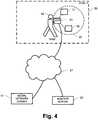
- Fig. 4shows a device 41 that has been stolen by a thief 42 in a zone 30.
- the stolen device 41communicates via Bluetooth to a group of other devices 17, 18 that are in the range 52 of the Bluetooth signal.
- the device 41is aware that it has been stolen, either by auto-detection, or by being informed by the monitoring center 20 after being reported stolen by its owner, and transmits an alert and/or a 'help' signal to the other devices 17, 18, where the signal contains descriptive information about the device 41.
- the descriptive informationmay be retrieved from the monitoring centre 20, or from a social network server 51 via network 27, and may include information uploaded there by the owner of the stolen device 41 prior to travelling. Such descriptive information might, for example, be used to create an alert that reads: "I'm lost!
- Devices 17, 18 that receive this alertmay be used by security personnel, for example in an airport, or they may belong to owners in the same social network group as the owner of the lost/stolen device 41. Agent 4 does not have to be installed on the devices 17, 18 in order for them to be capable of receiving the Bluetooth 'help' signal alert.
- Fig. 5is a functional flow diagram schematically illustrating steps in the process that the system of Fig. 1 carries out.
- the monitoring center of the systemdetects the location of a protected electronic device upon receiving location data from the agent located in the device. A zone around the location of the protected device is then selected or determined in step 61. The monitoring center of the system then retrieves 63 loss and/or theft data 62 for that zone. The theft data 62 is retrieved 63 from a theft database 22 ( Figure 1 ). If 65 the theft data 62 selected for the location in question is above a selected threshold (e.g. above zero items lost/stolen, above 1, above 2, etc.) for a selected period of time (e.g.
- a selected thresholde.g. above zero items lost/stolen, above 1, above 2, etc.
- the monitoring centersends an alert message to the device instructing the device to take action or set of actions 67, which could, for example, be the repeated sounding of an alert chime.
- the alert messageis processed by the agent and the agent responds by performing or initiating the specified action(s) 67, and the monitoring center may select the action content based on associated theft data stored in the database 22.
- action(s) 67may include the display of a text message that indicates the number of recent thefts, when such thefts were reported, the types of devices stolen, the size or approximate boundaries of the zone, etc.
- the monitoring centremay also refrain from sending any alert messages to a device that has been reported as stolen.
- the threshold, the selected period of time, and/or the zone sizemay in some embodiments be selected programmatically based on the number of protected devices in a given area, or on other selected factors. By way of example, in an area that includes a high density of monitored protected devices, such as in a large office, a higher threshold and/or a smaller zone size may be implemented.
- the processnext reverts to detecting 60 the location of the protected electronic device, so that the location is monitored in real time or near real time, and real time or near real time theft data 62 is also retrieved, so that current alerts, if any, can be given.
- Fig. 6is a functional flow diagram schematically illustrating steps in the process the system of Fig. 3 performs.
- the monitoring center of the systemcarries out steps 60 through 65 ( Figure 5 ) in relation to at least one proximal protected device A or B (12, 16 in Figure 3 ) to detect that one of the two devices A and B are in a theft risk zone, using theft data 62 that has previously been established in relation to the location of the devices.
- the systemdetects 71 the kinetics (i.e. state of motion and/or state of rest) of device A, and also detects 72 the kinetics of device B.
- the systemcalculates 73 changes in the relative spatial separation between the two devices A and B.
- 74 the separation increase beyond a selected thresholdan alert message is sent from the monitoring center to one or both proximal protected devices A and B to cause the sounding 75 thereby of an alert chime. If 74 the separation does not exceed the threshold, no alert is sounded. The process then reverts back to detecting 70 whether or not one of the devices is in a high theft risk zone. On first entry into the theft risk zone, a separation can be assumed (e.g. 1m) or calculated, or the initial separation can be left out of the analysis and only changes in separation can be calculated.
- Figure 3illustrates the situation where two proximal protected devices 12 and 16 are in the possession of the same person, but it will of course be readily understood by those of skill in the art without further illustration how the system and method may be modified to accommodate the situation where three or more proximal protected devices are in the possession of the same person, or where the proximal protected devices are in the possession of a related set of individuals (such as, for example, a family or a set of co-workers).
- a related set of individualssuch as, for example, a family or a set of co-workers.
- the specified action performed or initiated by the agent in response to the receipt of an alert message from the monitoring centermay comprise the generation of a pop-up or a series of pop-ups, which will act as a reminder to the laptop owner or user to be a little extra vigilant while in that location.
- the alert actioncould also, for example, be one or more of a sound, a series of sounds, a text message, a telephone call, a vibration, a series of vibrations, a light and a series of lights, etc.
- the monitoring centrehas significant data relating to locations of stolen devices. This can be used to calculate a time-averaged risk profile for each location.
- Datacould be made available to a third party which then provides location based services to its clients.
- a third partycould be an electronic social network or a map provider. Data provided in this way could be averaged over a week, a month, a year, or any other timescale, optionally with the most recent theft or loss events given the most weight. Any data supplied can be stripped of personal or identifiable information. Data trends can be calculated to show whether a location is becoming more or less of a risk, or is remaining stable.
- Information from such a data sourcecan be fed to review sites, such as restaurant review sites, hotel review sites, airport review sites, school review sites, city review sites, mall review sites, entertainment location review site, etc.; in addition, such trend information could be incorporated into the alert action messages.
- review sitessuch as restaurant review sites, hotel review sites, airport review sites, school review sites, city review sites, mall review sites, entertainment location review site, etc.; in addition, such trend information could be incorporated into the alert action messages.
- the deviceneed not actually call the monitoring centre directly. It may be location-aware and have access to theft-risk data compiled by the monitoring centre, and made available by the monitoring centre to a third party. As people are likely to be connected frequently to a social network, it may be more efficient to provide the alerts to the users of the devices via social networks. Alternatively, Wi-Fi hot spot providers may register to receive an alert whenever a lost or stolen protected device is determined to be in the vicinity and broadcast this alert to currently connected devices.
- Alerts provided to devicesmay be related to the number of thefts that generally occur in the area, as reported by the owners or users of the devices. Alerts may be related to the presence of stolen devices in an area. Alerts may be based on auto-detection of theft. For example, a device may monitor for triggers of likely theft, such as repeated incorrect passwords attempts or unusual movements.
- Steps in the flowchartsmay be performed in a different order to that illustrated, or they may be combined where shown separately.
- the monitoring centremay be a distributed monitoring centre.
- devices to be protectedcould detect unique information relating to their location, such as Wi-Fi signal strengths, beacons, photographs etc. This unique information could be sent directly or indirectly to a server which deduces the location in more meaningful terms, such as a grid reference or street address, from the unique information supplied. The more meaningful location information could then be provided to another server which retrieves the theft data for the location in question.
- the threshold for providing an alert to the heightened risk of theftmay be defined by the spatial density of thefts. For example, two thefts per week in a large zone may be below a selected threshold, whereas one theft per week in a much smaller zone may be above the selected threshold.
Landscapes
- Engineering & Computer Science (AREA)
- Physics & Mathematics (AREA)
- General Physics & Mathematics (AREA)
- Business, Economics & Management (AREA)
- Emergency Management (AREA)
- Computer Security & Cryptography (AREA)
- Computer Networks & Wireless Communication (AREA)
- Signal Processing (AREA)
- Computing Systems (AREA)
- Alarm Systems (AREA)
- Telephonic Communication Services (AREA)
- Telephone Function (AREA)
- Burglar Alarm Systems (AREA)
Description
- The present disclosure relates to the protection of electronic devices from loss or theft, and in particular to systems and methods for alerting an owner or legitimate user of an electronic device of the risk of loss or theft thereof.
- People are often forgetful or distracted in busy or transient spaces, such as airports, taxis, trains, hotels, shopping malls, etc. and thieves often take advantage of this to steal personal electronic computing or communications devices. Apart from being stolen, such devices are often lost in these busy areas. Since proprietary information is routinely stored on such devices, the need to protect such proprietary or sensitive data and to prevent the theft of such devices is self-evident.
- Laptops, and increasingly other electronic devices such as cell phones, PDAs, smart phones (e.g. Blackberry™, iPhone™), memory sticks, personal media devices (e.g. iPod™), gaming devices and personal computers, are often remotely tracked so that they can be recovered in the event of theft. Such tracking may be effected by sending location information to a remote storage site or an email server.
- While such tracking systems may be effective in the recovery of lost or stolen electronic devices, they do little to help prevent loss or theft in the first place. Accordingly, in an effort to discourage theft, owners of tracked or untracked personal electronic computing and communications devices sometimes apply irremovable and/or indelible warning stickers to such devices. However, perhaps in part because a thief may not see a warning sticker before or during the commission of a theft (and is not likely to return the stolen device to the owner if the thief sees the warning sticker afterwards), these sorts of warning stickers have shown in practice to provide only a limited amount of protection against theft.
US 2008/0094230 A1 describes a method and system for using location capabilities of mobile devices to permit users to avoid potentially harmful interactions. A location of the mobile device is determined, such as by GPS. Multiple threat factors relating to a potential danger proximate to the identified location can be mathematically combined to generate a situational threat value. When the situational threat value exceeds a threat threshold, a warning can be automatically presented upon the mobile device. In one aspect, the location is compared against at least one zone believed to be associated with a sexual predator, a criminal and/or a stalker. Geographical boundaries for the zone can be based upon automatically obtained information from a web-based source.JP 2007 072662 A - In an article dated April 14, 2009, XP055058977 "Mobile Application That Protects Your Children From Sex Offenders", an application for mobile phones is described that analyzes the threat level of the phone's locations based on a data base of registered sex offenders.
WO 2009/018125 A1 discloses a method and apparatus for protecting data in a portable electronic device. The device determines if it has been misplaced, lost or stolen, e. g. by a notification of the owner or by an appropriate signal by a service provider. Alternatively, the determination may be made based on leaving a defined operating region, or on observation of a prolonged period of inactivity or activity, or based on dialing patterns. In response to the determination, the device may enter a beacon mode in which it transmits its location, or a non-functional lock-down mode. A key to encrypted data may be destroyed or stored data erased.US 2009/183266 A1 discloses a method and a system for recovering a lost or stolen electronic device. The device determines whether or not it is used by a valid user, e. g. by password login, fingerprint recognition or other measures. If it is determined that the present user is not the valid user of the electronic device, it may gather information useful for recovery of the electronic device and transmit it to the valid user or to an anti-theft service provider.JP 2006 352604 A - This summary is not an extensive overview intended to delineate the scope of the subject matter that is described and claimed herein. The summary presents aspects of the subject matter in a simplified form to provide a basic understanding thereof, as a prelude to the detailed description that is presented below. Neither this summary nor the following detailed description purports to define or limit the invention; the invention is defined only by the claims.
- The subject matter described herein provides a system and method for the automatic provision of alerts to owners and/or legitimate users of electronic devices that are at potential risk of loss or theft. A frequently-updated database of locations of theft incidents, locations of losses and/or current or recent locations of lost or stolen electronic devices is used to provide alerts to the owner or legitimate user when his/her electronic device is detected to be in an elevated risk zone for loss or theft. The level of risk of the zone is ideally detected in real or near-real time.
- In embodiments of the disclosed subject matter, an agent in a protected electronic device communicates its location, or location specific information, at selected intervals to a monitoring center, which maintains a database of the location information of previously lost or stolen devices. If the location of the protected electronic device is determined to be within a zone of recent loss or theft activity (i.e. an elevated risk zone for loss or theft), the owner or user of the protected electronic device is alerted.
- In some embodiments, alerts can additionally be transmitted from one protected device to other protected devices in the same vicinity in order to provide an enhanced awareness of the risk of theft. In other embodiments, alerts may additionally or alternatively be transmitted to non-protected devices (such as, for example, cell phones or the like carried
by the owner or legitimate user of the protected device, or devices of the sort typically used or monitored by security organizations or personnel). - For a fuller understanding of the nature and advantages of the disclosed subject matter, as well as the preferred mode of use thereof, reference should be made to the following detailed description, read in conjunction with the accompanying drawings. In the drawings, like reference numerals designate like or similar steps or parts.
Fig. 1 is a schematic functional block diagram of a system and method for the automatic provision of alerts to owners of electronic devices in accordance with an embodiment of the disclosed subject matter.Fig. 2 is a schematic functional block diagram of a system and method for the automatic provision of shared alerts to owners of electronic devices in accordance with alternate embodiments of the disclosed subject matter.Fig. 3 is a schematic functional block diagram of a system and method for the automatic provision of alerts to owners of proximal electronic devices in accordance with alternate embodiments of the disclosed subject matter.Fig. 4 is a schematic functional block diagram of a system and method for the automatic provision of shared alerts to owners of electronic devices in accordance with alternate embodiments of the disclosed subject matter.Fig. 5 is a functional flow diagram schematically representing the alert provision process of the system and method ofFigure 1 .Fig. 6 is a functional flow diagram schematically representing the alert provision process of the system and method ofFigure 3 .- Agent - as used herein, is a software, hardware or firmware agent that is ideally persistent and stealthy, and that resides in a computer or other electronic device. The agent provides servicing functions which require communication with a remote server. The agent is tamper resistant and can be enabled for supporting and/or providing various services such as data delete, firewall protection, data encryption, location tracking, message notification, and software deployment and updates. An illustrative embodiment of an agent is found in the commercially available product Computrace Agent™. The technology underlying the Computrace Agent™ has been disclosed and patented in the U.S. and other countries, which patents have been commonly assigned to Absolute Software Corporation. See, for example,
U.S. Pat. Nos. 5,715,174 ;5,764,892 ;5,802,280 ;6,244,758 ;6,269,392 ;6,300,863 ; and6,507,914 ; and related foreign patents. Details of the persistent function of an agent are disclosed in U.S. Patent Application Publication Nos.US2005/0216757 andUS2006/0272020 . The technical disclosures of these documents are fully incorporated by reference as if fully set forth herein. It is feasible to use an equivalent agent to the Computrace Agent™, or less preferably an alternative agent with less functionality could be used. For the purposes of the present disclosure, the minimum functional attribute of the agent is to facilitate communications between the electronic device and a monitoring center or other remote computer or server. Communications may be initiated by the agent, by the monitoring center, or by both. - Host - This is the electronic device to be protected. Examples of a host include a laptop, cell phone, PDA, smart phone (e.g. Blackberry™, iPhone™), memory stick, personal media device (e.g. iPod™), gaming device, personal computer, and netbook. The agent resides in the host.
- Monitoring Center - This is a guardian server or other computer or server that the agent communicates with or sends a message to. It may be an email server or it may be a distribution of servers or other computers. For example, provided an internet connection is available to the host, an agent may call the monitoring center once a day (or at some other selected suitable interval) to report the location of the host, download software upgrades if there are any and repair any security modules that are or should be installed on the host. The interval between calls may be modified (e.g. reduced) if a host moves into a high risk area from a low risk area. In the embodiments disclosed herein, the agent sends host identification and location information to remote electronic storage located in the monitoring center, and/or any other data desired to be transferred. Communication to the monitoring center may be, for example, via the internet (wired or wireless), via a wired or wireless telephone network, via cable or via satellite. The functions of a monitoring centre may be incorporated or associated with an electronic social network server.
- The detailed descriptions within are presented largely in terms of methods or processes, symbolic representations of operations, functionalities and features of the invention. These method descriptions and representations are the means used by those skilled in the art to most effectively convey the substance of their work to others skilled in the art. A software implemented method or process is here, and generally, conceived to be a self-consistent sequence of steps leading to a desired result. These steps involve physical manipulations of physical quantities. Often, but not necessarily, these quantities take the form of electrical or magnetic signals capable of being stored, transferred, combined, compared, and otherwise manipulated. It will be further appreciated that the line between hardware, software and firmware is not always sharp, it being understood by those skilled in the art that software implemented processes may be embodied in hardware, firmware, or software, in the form of coded instructions such as in microcode and/or in stored programming instructions. In general, unless otherwise indicated, singular elements may be in the plural and vice versa with no loss of generality. The use of the masculine can refer to masculine, feminine or both. Drawings are not to scale.
- A schematic functional block diagram of a preferred embodiment is shown in
Fig. 1 . In many parts of the following detailed description, the subject matter has been explained in relation to stolen devices, but as would of course be evident to those of skill in the art, it applies equally as well to devices that are lost or are at risk of being lost. - A host
electronic device 10 such as a laptop comprises an agent 4 which can communicate regularly, non-periodically, randomly, semi-randomly or according to triggers, tomonitoring center 20 via theinternet 27, via some other telecommunications network, or via a combination of these. Short Message Service (SMS) messaging can be used for all or some of the communications, for example. - The agent 4 is located in
electronic memory 2 in thehost device 10. Thememory 2 may be divided into different components and/or different types of memory, and the agent 4 may be resident in more than one portion ofmemory 2. In thedevice 10, there is also alocation device 6, such as a GPS, or an A-GPS device, or some other device performing location determination. The locatingdevice 6 may be a component or module separate from thememory 2 as shown inFig. 1 , or it may be a module contained in or partially contained in thememory 2 of theelectronic device 10. There may be one, two ormore locating devices 6, each operating on a different principle or one acting as a backup for another. Theelectronic device 10 generally contains aprocessor 1 for processing computer readable instructions, such as those forming the agent 4, and reading/writing data to and from thememory 2 via abus 5. Theelectronic device 10 also includes aninterface 3 to theinternet 27 or other communication network. It should be appreciated that adevice 10 that connects to theinternet 27 may in some cases be considered part of theinternet 27. Thelink 28 to theinternet 27 or telecommunications network may be wired or wireless, or both. - The agent 4 sends data, which identifies the host and may include location information, to a
monitoring center 20 to be stored in remote storage device(s) 21. Location and/or host identification data may optionally be encrypted for privacy reasons. Themonitoring center 20 may be a server which contains aninterface 26 to thenetwork 27, abus 25 via which components internal to the server communicate and aprocessor 24 for processing computer readable instructions in thememory 21. Examples of instructions may be those included in one ormore program modules 23 for storing and/or encrypting incoming identification and location data frommultiple host devices 10, and for retrieving host identification data, host location data and theft records from one ormore databases 22. In some embodiments, the server may be formed from multiple distinct computers or computing devices that communicate over a network. - In the case of theft or loss of a protected
electronic device 41, the user or owner of thedevice 41 reports it to themonitoring center 20. Themonitoring centre 20 records location information for the stolendevice 41 in, for example, adatabase 22. Such a database can store the identification of a device, its location and the time it was at that location, and optionally encrypt some or all of this information. Theserver 20 also has information relating to the location ofother devices database 22 the details of any other device(s) 12 that are in the same general area orzone 30 as the stolendevice 41, the owner and/or user of such a device(s) 12 can be alerted to the presence in thezone 30 of a lost or stolendevice 41, and the possibility that there is athief 42 operating in thezone 30. In this example,devices zone 30 in which there is a lost/stolendevice 41. - The
thief 42 may have just stolen thedevice 41, or may have brought thedevice 41 into the area, or thedevice 41 may be being used or in the possession of an unwitting purchaser, who, not knowing the device was stolen, bought it from a thief. - As stolen device(s) 41 can be configured to report their location frequently (e.g. every minute, 5 minutes, ¼ hour), the
database 22 which contains the location details of lost and/or stolendevices 41 is continually up-to date, or as up-to-date as possible taking into account that thedevices 41 must have power and a communication link to themonitoring center 20. As a result, alerts relating to real-time or near-real-time information may be given to the users of device(s) 12 to indicate to them that they are in an area of elevated risk of theft. - The size of the area that is taken into account for risk assessment can be varied. It can be varied automatically, or it can be dependent on the precision at which location coordinates can be detected. A user could set the size of the risk zone to be taken into account. For example, the size of the zone to be evaluated could correspond to a single building, such as "
ZONE 1" 30, or it could correspond to a site with several buildings "ZONE 2" 31, which in the example shown includes anadditional thief 44 with a second stolendevice 43. - The size of the zone may be defined as an area within a certain distance of the device to be alerted. For example, the distance could be 10m, 100m, 500m, 2km, or other distance.
- An alert sent to a
device 12 may be an audio alert, such as a chime, a voice message or a notification of an SMS message. For example, a text message sent as an alert could be: "BEWARE: 1 lost/stolen laptop in this vicinity" or "BEWARE: 24 devices lost/stolen here in the last 3 days". In the example shown, the alert given todevice 12, where the zone of interest is "ZONE 2" 31 could be: "BEWARE: 2 lost/stolen laptops in this vicinity". The device can be configured to chime regularly, say every 10 seconds, as a constant reminder to the user of thedevice 12 that the device is still within azone - In some embodiments, the alert may additionally or alternatively be sent to a separate electronic device that does not include an agent 4. By way of example with reference to
Fig. 1 , if protectedelectronic device 12 is located withinzone 30, the owner or legitimate user of protectedelectronic device 12 may be alerted by text message sent to his/her non-protected cell phone. In further embodiments, the alert may additionally or alternatively be sent via text message or otherwise to the mobile phones of security personnel who are presently in thezone 30, whether or not their mobile phones include an agent 4. Security personnel or organizations may also in some embodiments register with themonitoring center 20 to automatically receive alerts that pertain to particular geographic regions. - In an extension to the exemplary embodiment described above, a protected
device 12 shown inFig. 2 may be configured to share any alerts it receives withneighboring devices thief 42 having in his possession a stolendevice 41 which has called into themonitoring center 20 with details of its location. The neighboringdevices device 12 via Bluetooth communication links. They may belong to the same person who usesdevice 12, or different people. Agroup 50 of different people may be connected because they, for example, belong to the same electronic social network managed by aserver 51 or they are tethering to gain access to theinternet 27. It may happen that some device(s) 13 linked together in this way may be outside therisk zone 30, but still receive an alert. As it is not essential to define the boundaries of thezone 30 precisely, and since the range of Bluetooth is not intended to be high, this is of no real consequence. Fig. 3 shows a situation where twodevices same person 19. Both devices are configured to communicate their location data to themonitoring centre 20 via anetwork 27. When amonitoring center 20 detects that one or both of thedevices theft risk zone 30, and provided the location determination mechanism is sensitive enough, say to a resolution of 1m or 2m, or in some cases maybe more, then the system can detect the approximate separation of the twodevices module 23 in themonitoring center 20, as and when thedevices devices devices - In another variant of this embodiment, each
device Bluetooth 29 or via anothernetwork 27. The application could run when the user is travelling, or could run only when the user is in anelevated risk zone 30 in order to conserve battery energy. If the separation exceeds a predefined distance, then an alarm could sound on one or both of thedevices Fig. 4 shows adevice 41 that has been stolen by athief 42 in azone 30. The stolendevice 41 communicates via Bluetooth to a group ofother devices range 52 of the Bluetooth signal. Thedevice 41 is aware that it has been stolen, either by auto-detection, or by being informed by themonitoring center 20 after being reported stolen by its owner, and transmits an alert and/or a 'help' signal to theother devices device 41. The descriptive information may be retrieved from themonitoring centre 20, or from asocial network server 51 vianetwork 27, and may include information uploaded there by the owner of the stolendevice 41 prior to travelling. Such descriptive information might, for example, be used to create an alert that reads: "I'm lost! I'm a laptop in a blue shoulder bag with a red maple leaf".Devices device 41. Agent 4 does not have to be installed on thedevices Fig. 5 is a functional flow diagram schematically illustrating steps in the process that the system ofFig. 1 carries out. Instep 60, the monitoring center of the system detects the location of a protected electronic device upon receiving location data from the agent located in the device. A zone around the location of the protected device is then selected or determined instep 61. The monitoring center of the system then retrieves 63 loss and/ortheft data 62 for that zone. Thetheft data 62 is retrieved 63 from a theft database 22 (Figure 1 ). If 65 thetheft data 62 selected for the location in question is above a selected threshold (e.g. above zero items lost/stolen, above 1, above 2, etc.) for a selected period of time (e.g. last 24 hours, last week, last 25 days, last 2 months, last year, year to date, per week, per month, all time as covered by the database, all time to the extent that all records including third party records can be accessed), then the monitoring center sends an alert message to the device instructing the device to take action or set ofactions 67, which could, for example, be the repeated sounding of an alert chime. The alert message is processed by the agent and the agent responds by performing or initiating the specified action(s) 67, and the monitoring center may select the action content based on associated theft data stored in thedatabase 22. For example, action(s) 67 may include the display of a text message that indicates the number of recent thefts, when such thefts were reported, the types of devices stolen, the size or approximate boundaries of the zone, etc. In some embodiments, the monitoring centre may also refrain from sending any alert messages to a device that has been reported as stolen.- The threshold, the selected period of time, and/or the zone size may in some embodiments be selected programmatically based on the number of protected devices in a given area, or on other selected factors. By way of example, in an area that includes a high density of monitored protected devices, such as in a large office, a higher threshold and/or a smaller zone size may be implemented.
- If 65 the
theft data 62 is not above a certain threshold, no alert message is sent and noaction 67 is taken. Whetheraction 67 is taken or not, the process next reverts to detecting 60 the location of the protected electronic device, so that the location is monitored in real time or near real time, and real time or near realtime theft data 62 is also retrieved, so that current alerts, if any, can be given. Fig. 6 is a functional flow diagram schematically illustrating steps in the process the system ofFig. 3 performs. Instep 70, the monitoring center of the system carries outsteps 60 through 65 (Figure 5 ) in relation to at least one proximal protected device A or B (12, 16 inFigure 3 ) to detect that one of the two devices A and B are in a theft risk zone, usingtheft data 62 that has previously been established in relation to the location of the devices. The system then detects 71 the kinetics (i.e. state of motion and/or state of rest) of device A, and also detects 72 the kinetics of device B. The system calculates 73 changes in the relative spatial separation between the two devices A and B. If 74 the separation increase beyond a selected threshold, an alert message is sent from the monitoring center to one or both proximal protected devices A and B to cause the sounding 75 thereby of an alert chime. If 74 the separation does not exceed the threshold, no alert is sounded. The process then reverts back to detecting 70 whether or not one of the devices is in a high theft risk zone. On first entry into the theft risk zone, a separation can be assumed (e.g. 1m) or calculated, or the initial separation can be left out of the analysis and only changes in separation can be calculated.Figure 3 illustrates the situation where two proximal protecteddevices - If the protected device is, for example, a laptop, the specified action performed or initiated by the agent in response to the receipt of an alert message from the monitoring center may comprise the generation of a pop-up or a series of pop-ups, which will act as a reminder to the laptop owner or user to be a little extra vigilant while in that location. The alert action could also, for example, be one or more of a sound, a series of sounds, a text message, a telephone call, a vibration, a series of vibrations, a light and a series of lights, etc.
- The monitoring centre has significant data relating to locations of stolen devices. This can be used to calculate a time-averaged risk profile for each location. Data could be made available to a third party which then provides location based services to its clients. For example, a third party could be an electronic social network or a map provider. Data provided in this way could be averaged over a week, a month, a year, or any other timescale, optionally with the most recent theft or loss events given the most weight. Any data supplied can be stripped of personal or identifiable information. Data trends can be calculated to show whether a location is becoming more or less of a risk, or is remaining stable. Information from such a data source can be fed to review sites, such as restaurant review sites, hotel review sites, airport review sites, school review sites, city review sites, mall review sites, entertainment location review site, etc.; in addition, such trend information could be incorporated into the alert action messages.
- Due to management of large numbers of protected devices calling into a monitoring centre, it may be beneficial to have the alert generation managed by a third party. This way, the device need not actually call the monitoring centre directly. It may be location-aware and have access to theft-risk data compiled by the monitoring centre, and made available by the monitoring centre to a third party. As people are likely to be connected frequently to a social network, it may be more efficient to provide the alerts to the users of the devices via social networks. Alternatively, Wi-Fi hot spot providers may register to receive an alert whenever a lost or stolen protected device is determined to be in the vicinity and broadcast this alert to currently connected devices.
- Alerts provided to devices may be related to the number of thefts that generally occur in the area, as reported by the owners or users of the devices. Alerts may be related to the presence of stolen devices in an area. Alerts may be based on auto-detection of theft. For example, a device may monitor for triggers of likely theft, such as repeated incorrect passwords attempts or unusual movements.
- Steps in the flowcharts may be performed in a different order to that illustrated, or they may be combined where shown separately.
- The monitoring centre may be a distributed monitoring centre. For example, devices to be protected could detect unique information relating to their location, such as Wi-Fi signal strengths, beacons, photographs etc. This unique information could be sent directly or indirectly to a server which deduces the location in more meaningful terms, such as a grid reference or street address, from the unique information supplied. The more meaningful location information could then be provided to another server which retrieves the theft data for the location in question.
- The threshold for providing an alert to the heightened risk of theft may be defined by the spatial density of thefts. For example, two thefts per week in a large zone may be below a selected threshold, whereas one theft per week in a much smaller zone may be above the selected threshold.
- The present description is of the best presently contemplated mode of carrying out the subject matter disclosed and claimed herein. The description is made for the purpose of illustrating the general principles of the subject matter and not be taken in a limiting sense; the subject matter can find utility in a variety of implementations without departing from the scope of the claims, which the define the invention as will be apparent to those of skill in the art from an understanding of the principles that underlie the subject matter.
Claims (12)
- A computer-implemented method of alerting electronic device users of theft risk, comprising:monitoring the locations of a plurality of electronic devices (10, 11, 12, 41, 43), wherein monitoring said locations comprises receiving identification of said monitored electronic devices and location information reported by said monitored electronic devices regarding their current locations;monitoring theft statuses of the monitored electronic devices (10, 11, 12, 41, 43), at least some of said theft statuses being based on theft events reported by users of the monitored electronic devices;
determining, based on the monitored locations and monitored theft statuses of the monitored electronic devices (10, 11, 12, 41, 43), that a first electronic device (10) of said plurality of monitored electronic devices is in a high theft risk zone (30, 31) by programmatically defining a territorial zone surrounding said first electronic device (10), retrieving data regarding one or more of said monitored devices located in the zone which have been reported as stolen, and establishing that a selected threshold number of monitored devices which have been reported as stolen have been located in the zone within a selected period of time; andin response to determining that the first electronic device (10) is in the high theft risk zone (30, 31), causing an alert to be provided to a user of the first electronic device (10);said method performed automatically by a computerized system. - The method of claim 1, wherein the theft statuses of the monitored electronic devices (10, 11, 12, 41, 43) are based on one or both of loss events reported by users of the monitored electronic devices, and the current location of monitored electronic devices that are reported as lost or stolen.
- The method of claim 1, wherein causing an alert to be provided to the user comprises transmitting an alert message to the first electronic device (10).
- The method of claim 3, further comprising, in response to the transmission of said alert message to the first electronic device, the emission by the first electronic device of an audible, tactile or visual alert to the user thereof.
- The method of claim 1, wherein causing an alert to be provided to the user consists of or comprises transmitting a text message to a second electronic device of said user.
- The method of claim 1, further comprising transmitting said alert message via a Bluetooth communications link to electronic devices in the vicinity of said first electronic device.
- The method of claim 1, further comprising, following the determination that a first electronic device (1) is located in a high theft risk zone:detecting based upon the identification and location information supplied by said monitored electronic devices that a second electronic device (16) of the same user is separated from said first electronic device (12) by a distance; andcausing an alarm to sound on one or both of said first and second electronic devices if said distance between said first and second electronic devices (12, 16) exceeds a selected threshold.
- The method of claim 1, wherein the territorial zone (30) surrounds a building or a site.
- The method of claim 1, wherein the step of monitoring the locations of a plurality of monitored electronic devices comprises:recording in a database (22) the identifications of the monitored electronic devices, the location information and times that the electronic devices were at said locations.
- The method of claim 1, wherein said reported theft events comprise locations of the theft events.
- The method of claim 1, wherein the high theft risk zone is a zone determined to have a high theft risk in substantially real-time.
- A computer system comprising one or more computing devices, said computer system programmed, via instructions represented in computer storage, to perform the method of claim 1.
Applications Claiming Priority (2)
| Application Number | Priority Date | Filing Date | Title |
|---|---|---|---|
| US24099309P | 2009-09-09 | 2009-09-09 | |
| PCT/CA2010/001417WO2011029195A1 (en) | 2009-09-09 | 2010-09-09 | Alert for real-time risk of theft or loss |
Publications (3)
| Publication Number | Publication Date |
|---|---|
| EP2476108A1 EP2476108A1 (en) | 2012-07-18 |
| EP2476108A4 EP2476108A4 (en) | 2013-05-22 |
| EP2476108B1true EP2476108B1 (en) | 2018-01-10 |
Family
ID=43647306
Family Applications (1)
| Application Number | Title | Priority Date | Filing Date |
|---|---|---|---|
| EP10814852.9AActiveEP2476108B1 (en) | 2009-09-09 | 2010-09-09 | Alert for real-time risk of theft or loss |
Country Status (6)
| Country | Link |
|---|---|
| US (4) | US8717172B2 (en) |
| EP (1) | EP2476108B1 (en) |
| AU (1) | AU2010292939B2 (en) |
| CA (1) | CA2773798A1 (en) |
| IN (1) | IN2012DN02732A (en) |
| WO (1) | WO2011029195A1 (en) |
Families Citing this family (43)
| Publication number | Priority date | Publication date | Assignee | Title |
|---|---|---|---|---|
| EP2404257A4 (en)* | 2009-03-06 | 2012-08-08 | Absolute Software Corp | Automatic control of a security protection mode of an electronic device |
| US8717172B2 (en) | 2009-09-09 | 2014-05-06 | Absolute Software Corporation | Alert for real-time risk of theft or loss |
| US20120235816A1 (en)* | 2011-03-17 | 2012-09-20 | Luis Estrada | Item location and theft prevention system |
| US20170026504A1 (en)* | 2011-07-13 | 2017-01-26 | Andrew Nichols | System and apparatus for mitigating of bad posture and property loss through computer-assisted appliance |
| US8402134B1 (en)* | 2011-12-12 | 2013-03-19 | Kaspersky Lab Zao | System and method for locating lost electronic devices |
| WO2013091077A1 (en)* | 2011-12-21 | 2013-06-27 | Otodata Wireless Network Inc. | Method and system for estimating a position of a target using a plurality of smartphones |
| JP5922947B2 (en)* | 2012-02-22 | 2016-05-24 | 富士重工業株式会社 | Outside environment recognition device and outside environment recognition method |
| CN103702277A (en)* | 2012-09-27 | 2014-04-02 | 联想(北京)有限公司 | Data transmission method and electronic equipment |
| US9412244B2 (en)* | 2012-10-18 | 2016-08-09 | Invue Security Products Inc. | Smart sensor line alarm system |
| US9928473B1 (en)* | 2013-01-30 | 2018-03-27 | Target Brands, Inc. | Booster centric resource allocation |
| US9035771B2 (en)* | 2013-01-31 | 2015-05-19 | Wal-Mart Stores, Inc. | Theft detection system |
| US10748529B1 (en)* | 2013-03-15 | 2020-08-18 | Apple Inc. | Voice activated device for use with a voice-based digital assistant |
| JP2016524209A (en) | 2013-04-23 | 2016-08-12 | カナリー コネクト,インコーポレイテッド | Security and / or monitoring device and system |
| US10496946B2 (en)* | 2013-11-06 | 2019-12-03 | Catalina Marketing Corporation | System and method for risk-based auditing of self-scan shopping baskets |
| JP6373680B2 (en)* | 2014-07-29 | 2018-08-15 | 株式会社東芝 | Electronic device, security processing method and program |
| US9520045B2 (en)* | 2014-09-02 | 2016-12-13 | Apple Inc. | Establishment and detection of breakage of wireless leash between devices |
| US10786408B2 (en) | 2014-10-17 | 2020-09-29 | Stryker Corporation | Person support apparatuses with exit detection systems |
| US9576466B2 (en)* | 2014-11-04 | 2017-02-21 | Canary Connect, Inc. | Backup contact for security/safety monitoring system |
| US9449479B2 (en)* | 2014-12-17 | 2016-09-20 | Colin Rogers | Security system |
| US9558372B2 (en)* | 2015-03-13 | 2017-01-31 | Microsoft Technology Licensing, Llc | Disablement of lost or stolen device |
| US9954870B2 (en)* | 2015-04-29 | 2018-04-24 | International Business Machines Corporation | System conversion in a networked computing environment |
| US9923908B2 (en) | 2015-04-29 | 2018-03-20 | International Business Machines Corporation | Data protection in a networked computing environment |
| US9462013B1 (en) | 2015-04-29 | 2016-10-04 | International Business Machines Corporation | Managing security breaches in a networked computing environment |
| US9609119B2 (en) | 2015-05-23 | 2017-03-28 | Microsoft Technology Licensing, Llc | Disablement of lost or stolen device |
| US9538335B1 (en)* | 2015-07-22 | 2017-01-03 | International Business Machines Corporation | Inferring device theft based on historical location data |
| US9613507B2 (en)* | 2015-07-27 | 2017-04-04 | Edwin Prugh Wilson | Alarm system and method |
| DE102015214892A1 (en)* | 2015-08-05 | 2017-02-09 | Robert Bosch Gmbh | Device and method for theft detection |
| US9686686B1 (en)* | 2015-08-05 | 2017-06-20 | Symantec Corporation | Locating a lost device using crowd GPS |
| KR20170034066A (en)* | 2015-09-18 | 2017-03-28 | 삼성전자주식회사 | Electronic device and control method thereof |
| KR20170052389A (en) | 2015-11-04 | 2017-05-12 | 삼성전자주식회사 | Alerting system and method for portable electronic device |
| US9818084B1 (en)* | 2015-12-09 | 2017-11-14 | Impinj, Inc. | RFID loss-prevention based on transition risk |
| US10115292B2 (en)* | 2016-05-19 | 2018-10-30 | Richard Abramson | System and method for automatic loss prevention of mobile communication devices |
| US10231078B1 (en)* | 2016-05-31 | 2019-03-12 | Infinite Leap, Inc. | Bluetooth low energy (BLE) real-time location system (RTLS) having simple transmitting tags, beacons and bridges, that use a combination of motion detection and RSSI measurements to determine room-location of the tags |
| US9924323B2 (en)* | 2016-08-19 | 2018-03-20 | Futurewei Technologies, Inc. | Apparatus and method for facilitating return of a mobile device |
| US10367832B2 (en) | 2017-01-27 | 2019-07-30 | Rapid7, Inc. | Reactive virtual security appliances |
| US11622275B2 (en) | 2017-02-21 | 2023-04-04 | Scorpion Security Products, Inc. | Geo-radius based mobile device management |
| CN110521223A (en) | 2017-02-21 | 2019-11-29 | 蝎子保安产品公司 | Mobile device management system and method |
| US20180308042A1 (en)* | 2017-04-25 | 2018-10-25 | Walmart Apollo, Llc | Product monitoring system and method using a multiple chip rfid tag |
| CN110351229B (en)* | 2018-04-04 | 2020-12-08 | 电信科学技术研究院有限公司 | Terminal UE (user equipment) management and control method and device |
| US10741037B2 (en)* | 2018-05-16 | 2020-08-11 | Avaya Inc. | Method and system for detecting inaudible sounds |
| CN109410493A (en)* | 2018-11-07 | 2019-03-01 | 于奎显 | A kind of method of mobile phone, tablet computer, intelligent wearable device burglar alarm |
| CA3085085A1 (en) | 2019-08-20 | 2021-02-20 | Stryker Corporation | Person support apparatus with adjustable exit detection zones |
| US20240349154A1 (en)* | 2023-04-14 | 2024-10-17 | Plume Design, Inc. | Computerized systems and methods for network expansion via connectivity nodes and event detection based therefrom |
Citations (4)
| Publication number | Priority date | Publication date | Assignee | Title |
|---|---|---|---|---|
| US20060184373A1 (en)* | 2005-02-03 | 2006-08-17 | International Business Machines Corporation | Method and system for quick and automatic police canvas operation of an identified crime scene area using an autodialer |
| JP2006352604A (en)* | 2005-06-17 | 2006-12-28 | Sharp Corp | Portable information terminal device |
| WO2009018125A1 (en)* | 2007-08-02 | 2009-02-05 | Applied Minds, Inc. | Method and apparatus for protecting data in a portable electronic device |
| US20090183266A1 (en)* | 2008-01-11 | 2009-07-16 | Lek Han Tan | Method and a system for recovering a lost or stolen electronic device |
Family Cites Families (104)
| Publication number | Priority date | Publication date | Assignee | Title |
|---|---|---|---|---|
| US4370753A (en)* | 1975-06-26 | 1983-01-25 | Motorola, Inc. | Battery saver for a tone coded signalling system |
| US4999621A (en) | 1989-07-27 | 1991-03-12 | Idx Technologies, Inc. | Tone code identification system |
| DE3932505C2 (en)* | 1989-09-28 | 2001-03-15 | Gao Ges Automation Org | Data carrier with an optically variable element |
| US5517429A (en)* | 1992-05-08 | 1996-05-14 | Harrison; Dana C. | Intelligent area monitoring system |
| US5497149A (en)* | 1993-09-02 | 1996-03-05 | Fast; Ray | Global security system |
| US5715174A (en)* | 1994-11-15 | 1998-02-03 | Absolute Software Corporation | Security apparatus and method |
| US6269392B1 (en)* | 1994-11-15 | 2001-07-31 | Christian Cotichini | Method and apparatus to monitor and locate an electronic device using a secured intelligent agent |
| US6300863B1 (en)* | 1994-11-15 | 2001-10-09 | Absolute Software Corporation | Method and apparatus to monitor and locate an electronic device using a secured intelligent agent via a global network |
| US6244758B1 (en)* | 1994-11-15 | 2001-06-12 | Absolute Software Corp. | Apparatus and method for monitoring electronic devices via a global network |
| US5825283A (en)* | 1996-07-03 | 1998-10-20 | Camhi; Elie | System for the security and auditing of persons and property |
| US5748084A (en)* | 1996-11-18 | 1998-05-05 | Isikoff; Jeremy M. | Device security system |
| US5821855A (en)* | 1997-02-28 | 1998-10-13 | Lewis; Tommy J. | Recognition responsive security system |
| US6084510A (en)* | 1997-04-18 | 2000-07-04 | Lemelson; Jerome H. | Danger warning and emergency response system and method |
| US6404966B1 (en)* | 1998-05-07 | 2002-06-11 | Nippon Telegraph And Telephone Corporation | Optical fiber |
| JP2002514832A (en)* | 1998-05-13 | 2002-05-21 | スペクトラ システムズ コーポレーション | Microlaser beam generating beads and structures and methods therefor |
| US5963131A (en)* | 1998-06-19 | 1999-10-05 | Lexent Technologies, Inc. | Anti-theft device with alarm screening |
| US6028514A (en)* | 1998-10-30 | 2000-02-22 | Lemelson Jerome H. | Personal emergency, safety warning system and method |
| US6692031B2 (en)* | 1998-12-31 | 2004-02-17 | Mcgrew Stephen P. | Quantum dot security device and method |
| US6908737B2 (en)* | 1999-04-15 | 2005-06-21 | Vitra Bioscience, Inc. | Systems and methods of conducting multiplexed experiments |
| EP1190236A1 (en)* | 1999-06-05 | 2002-03-27 | Zeptosens AG | Sensor platform and method for analysing multiple analytes |
| US20040209376A1 (en)* | 1999-10-01 | 2004-10-21 | Surromed, Inc. | Assemblies of differentiable segmented particles |
| NL1013245C2 (en)* | 1999-10-08 | 2001-04-10 | Nedap Nv | Open system technology. |
| US6614349B1 (en)* | 1999-12-03 | 2003-09-02 | Airbiquity Inc. | Facility and method for tracking physical assets |
| US6362736B1 (en)* | 2000-01-04 | 2002-03-26 | Lucent Technologies Inc. | Method and apparatus for automatic recovery of a stolen object |
| US6985656B2 (en)* | 2000-03-16 | 2006-01-10 | Lightsmyth Technologies Inc | Temperature-compensated planar waveguide optical apparatus |
| US7008794B2 (en)* | 2000-03-22 | 2006-03-07 | Axela Biosensors Inc. | Method and apparatus for assay for multiple analytes |
| JP2004500109A (en)* | 2000-03-22 | 2004-01-08 | クァンタム・ドット・コーポレイション | Use of semiconductor nanocrystals in bead-based nucleic acid assays |
| US6734420B2 (en)* | 2000-04-06 | 2004-05-11 | Quantum Dot Corporation | Differentiable spectral bar code methods and systems |
| US20020090650A1 (en)* | 2000-04-06 | 2002-07-11 | Quantum Dot Corporation | Two-dimensional spectral imaging system |
| EP1281063A1 (en)* | 2000-05-06 | 2003-02-05 | Zeptosens AG | Grating optical waveguide structure for multi-analyte determinations and the use thereof |
| US6509867B1 (en)* | 2000-05-08 | 2003-01-21 | Securatrak, Inc. | Article tracking device |
| WO2001090225A1 (en)* | 2000-05-22 | 2001-11-29 | Kabushiki Kaisya Advance | Novel method for forming polymer pattern |
| JP3639202B2 (en)* | 2000-07-05 | 2005-04-20 | 株式会社オプトウエア | Optical information recording apparatus and method, optical information reproducing apparatus and method, and optical information recording and reproducing apparatus and method |
| JP2002123948A (en)* | 2000-10-12 | 2002-04-26 | Optware:Kk | Optical information recording apparatus and method, optical information reproducing apparatus and method, optical information recording and reproducing apparatus and method, and optical information recording medium |
| US6760298B2 (en)* | 2000-12-08 | 2004-07-06 | Nagaoka & Co., Ltd. | Multiple data layer optical discs for detecting analytes |
| JP3639212B2 (en)* | 2000-12-11 | 2005-04-20 | 株式会社オプトウエア | Optical information recording method |
| US7848905B2 (en)* | 2000-12-26 | 2010-12-07 | Troxler Electronic Laboratories, Inc. | Methods, systems, and computer program products for locating and tracking objects |
| US7572642B2 (en)* | 2001-04-18 | 2009-08-11 | Ambrigen, Llc | Assay based on particles, which specifically bind with targets in spatially distributed characteristic patterns |
| WO2003056293A2 (en)* | 2001-07-10 | 2003-07-10 | Whitehead Institute For Biomedical Research | Small molecule microarrays |
| JP2003035892A (en)* | 2001-07-25 | 2003-02-07 | Fdk Corp | Optical shutter |
| JP2003149612A (en)* | 2001-08-27 | 2003-05-21 | Sumitomo Electric Ind Ltd | Optical component, optical encoder, optical decoder and optical communication system |
| US7756305B2 (en)* | 2002-01-23 | 2010-07-13 | The Regents Of The University Of California | Fast 3D cytometry for information in tissue engineering |
| NO315917B1 (en) | 2002-04-09 | 2003-11-10 | Filetrac As | System and method for positioning objects |
| US7138575B2 (en) | 2002-07-29 | 2006-11-21 | Accentus Llc | System and method for musical sonification of data |
| US7901630B2 (en)* | 2002-08-20 | 2011-03-08 | Illumina, Inc. | Diffraction grating-based encoded microparticle assay stick |
| US20050227252A1 (en)* | 2002-08-20 | 2005-10-13 | Moon John A | Diffraction grating-based encoded articles for multiplexed experiments |
| US7900836B2 (en)* | 2002-08-20 | 2011-03-08 | Illumina, Inc. | Optical reader system for substrates having an optically readable code |
| US7508608B2 (en)* | 2004-11-17 | 2009-03-24 | Illumina, Inc. | Lithographically fabricated holographic optical identification element |
| US7441703B2 (en)* | 2002-08-20 | 2008-10-28 | Illumina, Inc. | Optical reader for diffraction grating-based encoded optical identification elements |
| AU2003265583C1 (en)* | 2002-08-20 | 2009-05-21 | Cyvera Corporation | Diffraction grating-based optical identification element |
| US7619819B2 (en)* | 2002-08-20 | 2009-11-17 | Illumina, Inc. | Method and apparatus for drug product tracking using encoded optical identification elements |
| JP4485949B2 (en)* | 2002-08-20 | 2010-06-23 | シヴェラ コーポレイション | Grating-based coded microparticles for multiplex experiments |
| US7164533B2 (en)* | 2003-01-22 | 2007-01-16 | Cyvera Corporation | Hybrid random bead/chip based microarray |
| US20060160208A1 (en)* | 2004-02-19 | 2006-07-20 | Cyvera Corporation | Multi-well plate with alignment grooves for encoded microparticles |
| AU2003267192A1 (en)* | 2002-09-12 | 2004-04-30 | Cyvera Corporation | Method and apparatus for aligning elongated microbeads in order to interrogate the same |
| US20100255603A9 (en)* | 2002-09-12 | 2010-10-07 | Putnam Martin A | Method and apparatus for aligning microbeads in order to interrogate the same |
| US7321541B2 (en)* | 2002-10-09 | 2008-01-22 | Optware Corporation | Information recording method, reproducing method, and recording/reproducing method utilizing holography |
| US20040175842A1 (en)* | 2003-03-04 | 2004-09-09 | Roitman Daniel B. | Near-field and far-field encoding of microbeads for bioassays |
| WO2004102542A1 (en)* | 2003-05-13 | 2004-11-25 | Optware Corporation | Optical information recording/reproduction device and method |
| US7135635B2 (en) | 2003-05-28 | 2006-11-14 | Accentus, Llc | System and method for musical sonification of data parameters in a data stream |
| US6940407B2 (en)* | 2003-08-28 | 2005-09-06 | Motorola, Inc. | Method and apparatus for detecting loss and location of a portable communications device |
| US20060057729A1 (en)* | 2003-09-12 | 2006-03-16 | Illumina, Inc. | Diffraction grating-based encoded element having a substance disposed thereon |
| US6991114B2 (en)* | 2003-09-17 | 2006-01-31 | Vortechnics, Inc. | Apparatus for separating floating and non-floating particulate from a fluid stream |
| US20050149752A1 (en)* | 2003-12-29 | 2005-07-07 | Johnson Robert K. | System and method for tracking laptop computers |
| US20050270603A1 (en)* | 2004-02-19 | 2005-12-08 | Cyuera Corporation | Optical identification element using separate or partially overlapped diffraction gratings |
| US20060023310A1 (en)* | 2004-02-19 | 2006-02-02 | Putnam Martin A | Optical identification element using separate or partially overlapped diffraction gratings |
| US7433123B2 (en)* | 2004-02-19 | 2008-10-07 | Illumina, Inc. | Optical identification element having non-waveguide photosensitive substrate with diffraction grating therein |
| EP1733294A1 (en)* | 2004-03-26 | 2006-12-20 | Absolute Software Corporation | Persistent servicing agent |
| US20050238023A1 (en)* | 2004-03-26 | 2005-10-27 | Robertson Bruce W | Audio FSK encoded digital data packet embedded in the audio message portion of an EAS protocol transmission, and related methods |
| US8073427B2 (en) | 2004-06-30 | 2011-12-06 | At&T Intellectual Property I, L.P. | Remotely requesting an alert from a lost or stolen wireless device |
| JP2006085834A (en)* | 2004-09-16 | 2006-03-30 | Optware:Kk | Optical information recording apparatus and optical information reproducing apparatus |
| ATE459933T1 (en)* | 2004-11-16 | 2010-03-15 | Illumina Inc | METHOD AND APPARATUS FOR READING CODED MICROBALLS |
| WO2006055735A2 (en)* | 2004-11-16 | 2006-05-26 | Illumina, Inc | Scanner having spatial light modulator |
| US7604173B2 (en)* | 2004-11-16 | 2009-10-20 | Illumina, Inc. | Holographically encoded elements for microarray and other tagging labeling applications, and method and apparatus for making and reading the same |
| US20060134324A1 (en)* | 2004-11-17 | 2006-06-22 | Illumina, Inc. | Filament with easily removed protective coating and methods for stripping the same |
| EP1829002B1 (en)* | 2004-12-17 | 2009-03-25 | Nxp B.V. | Anti-theft method and apparatus with wireless technologies |
| CA2601572A1 (en)* | 2005-03-18 | 2006-09-28 | Gatekeeper Systems, Inc. | Power generation systems and methods for wheeled objects |
| US8418226B2 (en)* | 2005-03-18 | 2013-04-09 | Absolute Software Corporation | Persistent servicing agent |
| US20060232409A1 (en)* | 2005-04-18 | 2006-10-19 | Phoneguard Security | Alarm system using radio frequency identification tags |
| JP4668014B2 (en)* | 2005-09-05 | 2011-04-13 | シャープ株式会社 | Security status notification device, security status notification method, and computer program for causing computer to execute security status notification method |
| JP2007072662A (en) | 2005-09-06 | 2007-03-22 | Hitachi Ltd | Bus failure detection system |
| JP4734530B2 (en)* | 2005-09-09 | 2011-07-27 | 新オプトウエア株式会社 | retrieval method |
| US7623624B2 (en)* | 2005-11-22 | 2009-11-24 | Illumina, Inc. | Method and apparatus for labeling using optical identification elements characterized by X-ray diffraction |
| US10223891B2 (en)* | 2006-05-17 | 2019-03-05 | Peter Chlubek | Real-time multi-component web based travel safety system and method |
| US20080030331A1 (en)* | 2006-08-04 | 2008-02-07 | Aten International Co., Ltd. | Anti-thief electronic device and method thereof |
| US20080094230A1 (en) | 2006-10-23 | 2008-04-24 | Motorola, Inc. | Using location capabilities of a mobile device to permit users to avoid potentially harmful interactions |
| BRPI0806772B1 (en)* | 2007-01-16 | 2020-05-12 | Absolute Software Corporation | SYSTEM FOR REMOTE MONITORING OF A DEVICE, AND METHOD OF TRACKING A DEVICE |
| US8385883B2 (en)* | 2007-02-06 | 2013-02-26 | Qualcomm Incorporated | Apparatus and methods for locating, tracking and/or recovering a wireless communication device |
| US9083624B2 (en)* | 2007-03-02 | 2015-07-14 | Activetrak, Inc. | Mobile device or computer theft recovery system and method |
| WO2008122130A1 (en)* | 2007-04-05 | 2008-10-16 | Absolute Software Corporation | Distribution channel loss protection for electronic devices |
| US20080254811A1 (en)* | 2007-04-11 | 2008-10-16 | Palm, Inc. | System and method for monitoring locations of mobile devices |
| JP2009049568A (en)* | 2007-08-15 | 2009-03-05 | Fujifilm Corp | Reporting method and reporting system |
| US8490200B2 (en)* | 2008-03-25 | 2013-07-16 | Lenovo (Singapore) Pte. Ltd. | Techniques for capturing identifying information on a device user |
| US20100076794A1 (en)* | 2008-09-16 | 2010-03-25 | William Seippel | Systems For Valuating and Tracking Items of Property |
| US20120188064A1 (en) | 2009-02-17 | 2012-07-26 | Lookout. Inc., a California Corporation | System and method for remotely initiating playing of sound on a mobile device |
| US8717172B2 (en)* | 2009-09-09 | 2014-05-06 | Absolute Software Corporation | Alert for real-time risk of theft or loss |
| AU2010321633B2 (en)* | 2009-11-17 | 2014-09-04 | Absolute Software Corporation | Multiple device loss status retrieval without id provision |
| WO2011109083A2 (en) | 2010-03-01 | 2011-09-09 | Zazum, Inc. | Mobile device application |
| US8712432B2 (en)* | 2010-07-01 | 2014-04-29 | Absolute Software Corporation | Method and system for tracking mobile electronic devices while conserving cellular network resources |
| US20130101127A1 (en) | 2011-10-21 | 2013-04-25 | Research In Motion Limited | System and method for changing an activation state of an electronic device using acoustic signals |
| US9342974B2 (en)* | 2012-04-13 | 2016-05-17 | Intel Corporation | Autonomous aggregated search platform and methods using the same |
| US20140077932A1 (en)* | 2012-09-17 | 2014-03-20 | VISAGE The Global Pet Recognition Company Inc. | Method and system for alerting an owner of a lost animal |
| US20150022340A1 (en) | 2013-07-16 | 2015-01-22 | Leeo, Inc. | Electronic device with environmental monitoring |
| US8917186B1 (en)* | 2014-03-04 | 2014-12-23 | State Farm Mutual Automobile Insurance Company | Audio monitoring and sound identification process for remote alarms |
- 2010
- 2010-09-09USUS12/878,927patent/US8717172B2/enactiveActive
- 2010-09-09ININ2732DEN2012patent/IN2012DN02732A/enunknown
- 2010-09-09CACA2773798Apatent/CA2773798A1/ennot_activeAbandoned
- 2010-09-09WOPCT/CA2010/001417patent/WO2011029195A1/enactiveApplication Filing
- 2010-09-09AUAU2010292939Apatent/AU2010292939B2/enactiveActive
- 2010-09-09EPEP10814852.9Apatent/EP2476108B1/enactiveActive
- 2014
- 2014-03-18USUS14/217,861patent/US8878672B2/enactiveActive
- 2014-04-25USUS14/262,487patent/US9318010B2/enactiveActive
- 2014-06-05USUS14/297,432patent/US8902066B2/enactiveActive
Patent Citations (4)
| Publication number | Priority date | Publication date | Assignee | Title |
|---|---|---|---|---|
| US20060184373A1 (en)* | 2005-02-03 | 2006-08-17 | International Business Machines Corporation | Method and system for quick and automatic police canvas operation of an identified crime scene area using an autodialer |
| JP2006352604A (en)* | 2005-06-17 | 2006-12-28 | Sharp Corp | Portable information terminal device |
| WO2009018125A1 (en)* | 2007-08-02 | 2009-02-05 | Applied Minds, Inc. | Method and apparatus for protecting data in a portable electronic device |
| US20090183266A1 (en)* | 2008-01-11 | 2009-07-16 | Lek Han Tan | Method and a system for recovering a lost or stolen electronic device |
Also Published As
| Publication number | Publication date |
|---|---|
| AU2010292939A1 (en) | 2012-04-19 |
| WO2011029195A1 (en) | 2011-03-17 |
| US20140285343A1 (en) | 2014-09-25 |
| EP2476108A1 (en) | 2012-07-18 |
| US20150310714A1 (en) | 2015-10-29 |
| US8878672B2 (en) | 2014-11-04 |
| US20110057797A1 (en) | 2011-03-10 |
| US9318010B2 (en) | 2016-04-19 |
| EP2476108A4 (en) | 2013-05-22 |
| CA2773798A1 (en) | 2011-03-17 |
| US20140197952A1 (en) | 2014-07-17 |
| US8717172B2 (en) | 2014-05-06 |
| AU2010292939B2 (en) | 2014-09-18 |
| IN2012DN02732A (en) | 2015-09-11 |
| US8902066B2 (en) | 2014-12-02 |
Similar Documents
| Publication | Publication Date | Title |
|---|---|---|
| EP2476108B1 (en) | Alert for real-time risk of theft or loss | |
| US20220182820A1 (en) | Method and apparatus for protecting data in a portable electronic device | |
| US11864051B2 (en) | Systems and methods for monitoring and managing use of mobile electronic devices | |
| ES2658314T3 (en) | Apparatus and procedures for locating, tracking and / or retrieving a wireless communication device | |
| US8768294B2 (en) | Notification and tracking system for mobile devices | |
| EP2589232B1 (en) | Automatic creation and modification of dynamic geofences | |
| CA2799170C (en) | System and method for monitoring an area using nfc tags | |
| WO2008094685A1 (en) | System and method for monitoring the location of a tracking device | |
| CA2842782A1 (en) | Systems and methods for dynamically assessing and mitigating risk of an insured entity | |
| CN202617350U (en) | Mobile phone safety management and control system | |
| US20100194567A1 (en) | Location dependent monitoring for stolen devices | |
| EP3166294A1 (en) | Systems and methods for monitoring and managing use of mobile electronic devices | |
| US20180033266A1 (en) | Automated motion disturbance detection and alerting | |
| EP2502178B1 (en) | Multiple device loss status retrieval without id provision | |
| EP2321761B1 (en) | Invocation of system services through auxiliary interface | |
| EP2321758B1 (en) | Display of information through auxiliary user interface | |
| RU2364939C2 (en) | System, method and device of information provision of life safety |
Legal Events
| Date | Code | Title | Description |
|---|---|---|---|
| PUAI | Public reference made under article 153(3) epc to a published international application that has entered the european phase | Free format text:ORIGINAL CODE: 0009012 | |
| 17P | Request for examination filed | Effective date:20120328 | |
| AK | Designated contracting states | Kind code of ref document:A1 Designated state(s):AL AT BE BG CH CY CZ DE DK EE ES FI FR GB GR HR HU IE IS IT LI LT LU LV MC MK MT NL NO PL PT RO SE SI SK SM TR | |
| DAX | Request for extension of the european patent (deleted) | ||
| A4 | Supplementary search report drawn up and despatched | Effective date:20130418 | |
| RIC1 | Information provided on ipc code assigned before grant | Ipc:G08B 13/14 20060101AFI20130412BHEP Ipc:G08B 21/22 20060101ALI20130412BHEP Ipc:G08B 31/00 20060101ALI20130412BHEP | |
| 17Q | First examination report despatched | Effective date:20160624 | |
| GRAP | Despatch of communication of intention to grant a patent | Free format text:ORIGINAL CODE: EPIDOSNIGR1 | |
| INTG | Intention to grant announced | Effective date:20170731 | |
| GRAS | Grant fee paid | Free format text:ORIGINAL CODE: EPIDOSNIGR3 | |
| GRAA | (expected) grant | Free format text:ORIGINAL CODE: 0009210 | |
| AK | Designated contracting states | Kind code of ref document:B1 Designated state(s):AL AT BE BG CH CY CZ DE DK EE ES FI FR GB GR HR HU IE IS IT LI LT LU LV MC MK MT NL NO PL PT RO SE SI SK SM TR | |
| REG | Reference to a national code | Ref country code:GB Ref legal event code:FG4D | |
| REG | Reference to a national code | Ref country code:CH Ref legal event code:EP Ref country code:AT Ref legal event code:REF Ref document number:963182 Country of ref document:AT Kind code of ref document:T Effective date:20180115 | |
| REG | Reference to a national code | Ref country code:IE Ref legal event code:FG4D | |
| REG | Reference to a national code | Ref country code:DE Ref legal event code:R096 Ref document number:602010048017 Country of ref document:DE | |
| REG | Reference to a national code | Ref country code:NL Ref legal event code:MP Effective date:20180110 | |
| REG | Reference to a national code | Ref country code:AT Ref legal event code:MK05 Ref document number:963182 Country of ref document:AT Kind code of ref document:T Effective date:20180110 | |
| PG25 | Lapsed in a contracting state [announced via postgrant information from national office to epo] | Ref country code:NL Free format text:LAPSE BECAUSE OF FAILURE TO SUBMIT A TRANSLATION OF THE DESCRIPTION OR TO PAY THE FEE WITHIN THE PRESCRIBED TIME-LIMIT Effective date:20180110 | |
| PG25 | Lapsed in a contracting state [announced via postgrant information from national office to epo] | Ref country code:NO Free format text:LAPSE BECAUSE OF FAILURE TO SUBMIT A TRANSLATION OF THE DESCRIPTION OR TO PAY THE FEE WITHIN THE PRESCRIBED TIME-LIMIT Effective date:20180410 Ref country code:ES Free format text:LAPSE BECAUSE OF FAILURE TO SUBMIT A TRANSLATION OF THE DESCRIPTION OR TO PAY THE FEE WITHIN THE PRESCRIBED TIME-LIMIT Effective date:20180110 Ref country code:HR Free format text:LAPSE BECAUSE OF FAILURE TO SUBMIT A TRANSLATION OF THE DESCRIPTION OR TO PAY THE FEE WITHIN THE PRESCRIBED TIME-LIMIT Effective date:20180110 Ref country code:LT Free format text:LAPSE BECAUSE OF FAILURE TO SUBMIT A TRANSLATION OF THE DESCRIPTION OR TO PAY THE FEE WITHIN THE PRESCRIBED TIME-LIMIT Effective date:20180110 Ref country code:CY Free format text:LAPSE BECAUSE OF FAILURE TO SUBMIT A TRANSLATION OF THE DESCRIPTION OR TO PAY THE FEE WITHIN THE PRESCRIBED TIME-LIMIT Effective date:20180110 Ref country code:FI Free format text:LAPSE BECAUSE OF FAILURE TO SUBMIT A TRANSLATION OF THE DESCRIPTION OR TO PAY THE FEE WITHIN THE PRESCRIBED TIME-LIMIT Effective date:20180110 | |
| PG25 | Lapsed in a contracting state [announced via postgrant information from national office to epo] | Ref country code:IS Free format text:LAPSE BECAUSE OF FAILURE TO SUBMIT A TRANSLATION OF THE DESCRIPTION OR TO PAY THE FEE WITHIN THE PRESCRIBED TIME-LIMIT Effective date:20180510 Ref country code:GR Free format text:LAPSE BECAUSE OF FAILURE TO SUBMIT A TRANSLATION OF THE DESCRIPTION OR TO PAY THE FEE WITHIN THE PRESCRIBED TIME-LIMIT Effective date:20180411 Ref country code:PL Free format text:LAPSE BECAUSE OF FAILURE TO SUBMIT A TRANSLATION OF THE DESCRIPTION OR TO PAY THE FEE WITHIN THE PRESCRIBED TIME-LIMIT Effective date:20180110 Ref country code:LV Free format text:LAPSE BECAUSE OF FAILURE TO SUBMIT A TRANSLATION OF THE DESCRIPTION OR TO PAY THE FEE WITHIN THE PRESCRIBED TIME-LIMIT Effective date:20180110 Ref country code:SE Free format text:LAPSE BECAUSE OF FAILURE TO SUBMIT A TRANSLATION OF THE DESCRIPTION OR TO PAY THE FEE WITHIN THE PRESCRIBED TIME-LIMIT Effective date:20180110 Ref country code:AT Free format text:LAPSE BECAUSE OF FAILURE TO SUBMIT A TRANSLATION OF THE DESCRIPTION OR TO PAY THE FEE WITHIN THE PRESCRIBED TIME-LIMIT Effective date:20180110 Ref country code:BG Free format text:LAPSE BECAUSE OF FAILURE TO SUBMIT A TRANSLATION OF THE DESCRIPTION OR TO PAY THE FEE WITHIN THE PRESCRIBED TIME-LIMIT Effective date:20180410 | |
| REG | Reference to a national code | Ref country code:FR Ref legal event code:PLFP Year of fee payment:9 | |
| REG | Reference to a national code | Ref country code:DE Ref legal event code:R097 Ref document number:602010048017 Country of ref document:DE | |
| PG25 | Lapsed in a contracting state [announced via postgrant information from national office to epo] | Ref country code:EE Free format text:LAPSE BECAUSE OF FAILURE TO SUBMIT A TRANSLATION OF THE DESCRIPTION OR TO PAY THE FEE WITHIN THE PRESCRIBED TIME-LIMIT Effective date:20180110 Ref country code:AL Free format text:LAPSE BECAUSE OF FAILURE TO SUBMIT A TRANSLATION OF THE DESCRIPTION OR TO PAY THE FEE WITHIN THE PRESCRIBED TIME-LIMIT Effective date:20180110 Ref country code:IT Free format text:LAPSE BECAUSE OF FAILURE TO SUBMIT A TRANSLATION OF THE DESCRIPTION OR TO PAY THE FEE WITHIN THE PRESCRIBED TIME-LIMIT Effective date:20180110 Ref country code:RO Free format text:LAPSE BECAUSE OF FAILURE TO SUBMIT A TRANSLATION OF THE DESCRIPTION OR TO PAY THE FEE WITHIN THE PRESCRIBED TIME-LIMIT Effective date:20180110 | |
| PLBE | No opposition filed within time limit | Free format text:ORIGINAL CODE: 0009261 | |
| STAA | Information on the status of an ep patent application or granted ep patent | Free format text:STATUS: NO OPPOSITION FILED WITHIN TIME LIMIT | |
| PG25 | Lapsed in a contracting state [announced via postgrant information from national office to epo] | Ref country code:CZ Free format text:LAPSE BECAUSE OF FAILURE TO SUBMIT A TRANSLATION OF THE DESCRIPTION OR TO PAY THE FEE WITHIN THE PRESCRIBED TIME-LIMIT Effective date:20180110 Ref country code:SM Free format text:LAPSE BECAUSE OF FAILURE TO SUBMIT A TRANSLATION OF THE DESCRIPTION OR TO PAY THE FEE WITHIN THE PRESCRIBED TIME-LIMIT Effective date:20180110 Ref country code:DK Free format text:LAPSE BECAUSE OF FAILURE TO SUBMIT A TRANSLATION OF THE DESCRIPTION OR TO PAY THE FEE WITHIN THE PRESCRIBED TIME-LIMIT Effective date:20180110 Ref country code:SK Free format text:LAPSE BECAUSE OF FAILURE TO SUBMIT A TRANSLATION OF THE DESCRIPTION OR TO PAY THE FEE WITHIN THE PRESCRIBED TIME-LIMIT Effective date:20180110 | |
| 26N | No opposition filed | Effective date:20181011 | |
| PG25 | Lapsed in a contracting state [announced via postgrant information from national office to epo] | Ref country code:SI Free format text:LAPSE BECAUSE OF FAILURE TO SUBMIT A TRANSLATION OF THE DESCRIPTION OR TO PAY THE FEE WITHIN THE PRESCRIBED TIME-LIMIT Effective date:20180110 | |
| PG25 | Lapsed in a contracting state [announced via postgrant information from national office to epo] | Ref country code:MC Free format text:LAPSE BECAUSE OF FAILURE TO SUBMIT A TRANSLATION OF THE DESCRIPTION OR TO PAY THE FEE WITHIN THE PRESCRIBED TIME-LIMIT Effective date:20180110 | |
| REG | Reference to a national code | Ref country code:CH Ref legal event code:PL | |
| REG | Reference to a national code | Ref country code:BE Ref legal event code:MM Effective date:20180930 | |
| REG | Reference to a national code | Ref country code:IE Ref legal event code:MM4A | |
| PG25 | Lapsed in a contracting state [announced via postgrant information from national office to epo] | Ref country code:LU Free format text:LAPSE BECAUSE OF NON-PAYMENT OF DUE FEES Effective date:20180909 | |
| PG25 | Lapsed in a contracting state [announced via postgrant information from national office to epo] | Ref country code:IE Free format text:LAPSE BECAUSE OF NON-PAYMENT OF DUE FEES Effective date:20180909 | |
| PG25 | Lapsed in a contracting state [announced via postgrant information from national office to epo] | Ref country code:CH Free format text:LAPSE BECAUSE OF NON-PAYMENT OF DUE FEES Effective date:20180930 Ref country code:BE Free format text:LAPSE BECAUSE OF NON-PAYMENT OF DUE FEES Effective date:20180930 Ref country code:LI Free format text:LAPSE BECAUSE OF NON-PAYMENT OF DUE FEES Effective date:20180930 | |
| PG25 | Lapsed in a contracting state [announced via postgrant information from national office to epo] | Ref country code:MT Free format text:LAPSE BECAUSE OF NON-PAYMENT OF DUE FEES Effective date:20180909 | |
| PG25 | Lapsed in a contracting state [announced via postgrant information from national office to epo] | Ref country code:TR Free format text:LAPSE BECAUSE OF FAILURE TO SUBMIT A TRANSLATION OF THE DESCRIPTION OR TO PAY THE FEE WITHIN THE PRESCRIBED TIME-LIMIT Effective date:20180110 | |
| PG25 | Lapsed in a contracting state [announced via postgrant information from national office to epo] | Ref country code:PT Free format text:LAPSE BECAUSE OF FAILURE TO SUBMIT A TRANSLATION OF THE DESCRIPTION OR TO PAY THE FEE WITHIN THE PRESCRIBED TIME-LIMIT Effective date:20180110 Ref country code:HU Free format text:LAPSE BECAUSE OF FAILURE TO SUBMIT A TRANSLATION OF THE DESCRIPTION OR TO PAY THE FEE WITHIN THE PRESCRIBED TIME-LIMIT; INVALID AB INITIO Effective date:20100909 | |
| PG25 | Lapsed in a contracting state [announced via postgrant information from national office to epo] | Ref country code:MK Free format text:LAPSE BECAUSE OF NON-PAYMENT OF DUE FEES Effective date:20180110 | |
| P01 | Opt-out of the competence of the unified patent court (upc) registered | Effective date:20230530 | |
| PGFP | Annual fee paid to national office [announced via postgrant information from national office to epo] | Ref country code:DE Payment date:20240927 Year of fee payment:15 | |
| PGFP | Annual fee paid to national office [announced via postgrant information from national office to epo] | Ref country code:GB Payment date:20240927 Year of fee payment:15 | |
| PGFP | Annual fee paid to national office [announced via postgrant information from national office to epo] | Ref country code:FR Payment date:20240925 Year of fee payment:15 |