EP2475962B1 - Systems and methods for detecting bifurcations - Google Patents
Systems and methods for detecting bifurcationsDownload PDFInfo
- Publication number
- EP2475962B1 EP2475962B1EP10775882.3AEP10775882AEP2475962B1EP 2475962 B1EP2475962 B1EP 2475962B1EP 10775882 AEP10775882 AEP 10775882AEP 2475962 B1EP2475962 B1EP 2475962B1
- Authority
- EP
- European Patent Office
- Prior art keywords
- navigation device
- possible segment
- segment
- location measurements
- heading
- Prior art date
- Legal status (The legal status is an assumption and is not a legal conclusion. Google has not performed a legal analysis and makes no representation as to the accuracy of the status listed.)
- Active
Links
Images


Classifications
- G—PHYSICS
- G06—COMPUTING OR CALCULATING; COUNTING
- G06F—ELECTRIC DIGITAL DATA PROCESSING
- G06F3/00—Input arrangements for transferring data to be processed into a form capable of being handled by the computer; Output arrangements for transferring data from processing unit to output unit, e.g. interface arrangements
- G06F3/06—Digital input from, or digital output to, record carriers, e.g. RAID, emulated record carriers or networked record carriers
- G06F3/0601—Interfaces specially adapted for storage systems
- G06F3/0628—Interfaces specially adapted for storage systems making use of a particular technique
- G06F3/0662—Virtualisation aspects
- G06F3/0664—Virtualisation aspects at device level, e.g. emulation of a storage device or system
- G—PHYSICS
- G01—MEASURING; TESTING
- G01C—MEASURING DISTANCES, LEVELS OR BEARINGS; SURVEYING; NAVIGATION; GYROSCOPIC INSTRUMENTS; PHOTOGRAMMETRY OR VIDEOGRAMMETRY
- G01C21/00—Navigation; Navigational instruments not provided for in groups G01C1/00 - G01C19/00
- G01C21/26—Navigation; Navigational instruments not provided for in groups G01C1/00 - G01C19/00 specially adapted for navigation in a road network
- G—PHYSICS
- G01—MEASURING; TESTING
- G01C—MEASURING DISTANCES, LEVELS OR BEARINGS; SURVEYING; NAVIGATION; GYROSCOPIC INSTRUMENTS; PHOTOGRAMMETRY OR VIDEOGRAMMETRY
- G01C5/00—Measuring height; Measuring distances transverse to line of sight; Levelling between separated points; Surveyors' levels
- G01C5/06—Measuring height; Measuring distances transverse to line of sight; Levelling between separated points; Surveyors' levels by using barometric means
- G—PHYSICS
- G01—MEASURING; TESTING
- G01S—RADIO DIRECTION-FINDING; RADIO NAVIGATION; DETERMINING DISTANCE OR VELOCITY BY USE OF RADIO WAVES; LOCATING OR PRESENCE-DETECTING BY USE OF THE REFLECTION OR RERADIATION OF RADIO WAVES; ANALOGOUS ARRANGEMENTS USING OTHER WAVES
- G01S19/00—Satellite radio beacon positioning systems; Determining position, velocity or attitude using signals transmitted by such systems
- G01S19/01—Satellite radio beacon positioning systems transmitting time-stamped messages, e.g. GPS [Global Positioning System], GLONASS [Global Orbiting Navigation Satellite System] or GALILEO
- G01S19/13—Receivers
- G01S19/14—Receivers specially adapted for specific applications
- G—PHYSICS
- G06—COMPUTING OR CALCULATING; COUNTING
- G06F—ELECTRIC DIGITAL DATA PROCESSING
- G06F3/00—Input arrangements for transferring data to be processed into a form capable of being handled by the computer; Output arrangements for transferring data from processing unit to output unit, e.g. interface arrangements
- G06F3/06—Digital input from, or digital output to, record carriers, e.g. RAID, emulated record carriers or networked record carriers
- G06F3/0601—Interfaces specially adapted for storage systems
- G06F3/0602—Interfaces specially adapted for storage systems specifically adapted to achieve a particular effect
- G06F3/0604—Improving or facilitating administration, e.g. storage management
- G06F3/0605—Improving or facilitating administration, e.g. storage management by facilitating the interaction with a user or administrator
- G—PHYSICS
- G06—COMPUTING OR CALCULATING; COUNTING
- G06F—ELECTRIC DIGITAL DATA PROCESSING
- G06F3/00—Input arrangements for transferring data to be processed into a form capable of being handled by the computer; Output arrangements for transferring data from processing unit to output unit, e.g. interface arrangements
- G06F3/06—Digital input from, or digital output to, record carriers, e.g. RAID, emulated record carriers or networked record carriers
- G06F3/0601—Interfaces specially adapted for storage systems
- G06F3/0668—Interfaces specially adapted for storage systems adopting a particular infrastructure
- G06F3/0671—In-line storage system
- G06F3/0673—Single storage device
- G06F3/0679—Non-volatile semiconductor memory device, e.g. flash memory, one time programmable memory [OTP]
- H—ELECTRICITY
- H04—ELECTRIC COMMUNICATION TECHNIQUE
- H04L—TRANSMISSION OF DIGITAL INFORMATION, e.g. TELEGRAPHIC COMMUNICATION
- H04L65/00—Network arrangements, protocols or services for supporting real-time applications in data packet communication
- H04L65/10—Architectures or entities
- H04L65/1059—End-user terminal functionalities specially adapted for real-time communication
- H—ELECTRICITY
- H04—ELECTRIC COMMUNICATION TECHNIQUE
- H04L—TRANSMISSION OF DIGITAL INFORMATION, e.g. TELEGRAPHIC COMMUNICATION
- H04L65/00—Network arrangements, protocols or services for supporting real-time applications in data packet communication
- H04L65/1066—Session management
- H04L65/1069—Session establishment or de-establishment
- H—ELECTRICITY
- H04—ELECTRIC COMMUNICATION TECHNIQUE
- H04L—TRANSMISSION OF DIGITAL INFORMATION, e.g. TELEGRAPHIC COMMUNICATION
- H04L67/00—Network arrangements or protocols for supporting network services or applications
- H04L67/01—Protocols
- H04L67/12—Protocols specially adapted for proprietary or special-purpose networking environments, e.g. medical networks, sensor networks, networks in vehicles or remote metering networks
- H—ELECTRICITY
- H04—ELECTRIC COMMUNICATION TECHNIQUE
- H04M—TELEPHONIC COMMUNICATION
- H04M1/00—Substation equipment, e.g. for use by subscribers
- H04M1/253—Telephone sets using digital voice transmission
- H04M1/2535—Telephone sets using digital voice transmission adapted for voice communication over an Internet Protocol [IP] network
- H—ELECTRICITY
- H04—ELECTRIC COMMUNICATION TECHNIQUE
- H04M—TELEPHONIC COMMUNICATION
- H04M1/00—Substation equipment, e.g. for use by subscribers
- H04M1/60—Substation equipment, e.g. for use by subscribers including speech amplifiers
- H04M1/6033—Substation equipment, e.g. for use by subscribers including speech amplifiers for providing handsfree use or a loudspeaker mode in telephone sets
- H04M1/6041—Portable telephones adapted for handsfree use
- H04M1/6075—Portable telephones adapted for handsfree use adapted for handsfree use in a vehicle
- Y—GENERAL TAGGING OF NEW TECHNOLOGICAL DEVELOPMENTS; GENERAL TAGGING OF CROSS-SECTIONAL TECHNOLOGIES SPANNING OVER SEVERAL SECTIONS OF THE IPC; TECHNICAL SUBJECTS COVERED BY FORMER USPC CROSS-REFERENCE ART COLLECTIONS [XRACs] AND DIGESTS
- Y04—INFORMATION OR COMMUNICATION TECHNOLOGIES HAVING AN IMPACT ON OTHER TECHNOLOGY AREAS
- Y04S—SYSTEMS INTEGRATING TECHNOLOGIES RELATED TO POWER NETWORK OPERATION, COMMUNICATION OR INFORMATION TECHNOLOGIES FOR IMPROVING THE ELECTRICAL POWER GENERATION, TRANSMISSION, DISTRIBUTION, MANAGEMENT OR USAGE, i.e. SMART GRIDS
- Y04S40/00—Systems for electrical power generation, transmission, distribution or end-user application management characterised by the use of communication or information technologies, or communication or information technology specific aspects supporting them
- Y04S40/18—Network protocols supporting networked applications, e.g. including control of end-device applications over a network
Definitions
- This disclosuregenerally relates to systems and methods for bifurcation detection. At least some example embodiments relate to portable navigation devices (so-called PNDs).
- PNDsportable navigation devices
- WO 2008/072293 A1discloses a navigation device having a function for performing route research in prediction of a deviation of a vehicle from a recommended route.
- Example embodimentsprovide methods for bifurcation detection.
- Positioning systemssuch as gyroscope and GPS are used to display a position on a correct leg of the bifurcation.
- computer softwareincluding one or more software modules operable, when executed in an execution environment, to cause a computer to perform a method as claimed in claim 13.
- Such existing hardwaremay include one or more Central Processing Units (CPUs), digital signal processors (DSPs), application-specific-integrated-circuits, field programmable gate arrays (FPGAs) computers or the like.
- CPUsCentral Processing Units
- DSPsdigital signal processors
- FPGAsfield programmable gate arrays
- the software implemented aspects of example embodimentsare typically encoded on some form of computer readable medium or implemented over some type of transmission medium.
- the computer readable mediummay be magnetic (e.g., a floppy disk or a hard drive) or optical (e.g., a compact disk read only memory, or "CD ROM"), and may be read only or random access.
- the transmission mediummay be twisted wire pairs, coaxial cable, optical fiber, or some other suitable transmission medium known to the art. Example embodiments are not limited by these aspects of any given implementation.
- a navigation deviceis intended to include (without limitation) any type of route planning and navigation device, irrespective of whether that device is embodied as a PND, mobile telephone or portable digital assistant (PDA) executing route planning and navigation software.
- the navigation deviceuses and/or measures its location.
- FIG. 1illustrates an example view of Global Positioning System (GPS), usable by navigation devices.
- GPSGlobal Positioning System
- NAVSTARthe GPS incorporates a plurality of satellites which orbit the earth in extremely precise orbits. Based on these precise orbits, GPS satellites can relay their location to any number of receiving units.
- the GPS systemis implemented when a device, specially equipped to receive GPS data, begins scanning radio frequencies for GPS satellite signals. Upon receiving a radio signal from a GPS satellite, the device determines the precise location of that satellite via one of a plurality of different conventional methods. The device will continue scanning, in most instances, for signals until it has acquired at least three different satellite signals (noting that position is not normally, but can be determined, with only two signals using other triangulation techniques). Implementing geometric triangulation, the receiver utilizes the three known positions to determine its own two-dimensional position relative to the satellites. This can be done in a known manner. Additionally, acquiring a fourth satellite signal will allow the receiving device to calculate its three dimensional position by the same geometrical calculation in a known manner. The position and velocity data can be updated in real time on a continuous basis by an unlimited number of users.
- the GPS systemis denoted generally by reference numeral 100.
- a plurality of satellites 120are in orbit about the earth 124. The orbit of each satellite 120 is not necessarily synchronous with the orbits of other satellites 120 and, in fact, is likely asynchronous.
- a GPS receiver 140is shown receiving spread spectrum GPS satellite signals 160 from the various satellites 120.
- the spread spectrum signals 160continuously transmitted from each satellite 120, utilize a highly accurate frequency standard accomplished with an extremely accurate atomic clock.
- Each satellite 120as part of its data signal transmission 160, transmits a data stream indicative of that particular satellite 120.
- the GPS receiver device 140generally acquires spread spectrum GPS satellite signals 160 from at least three satellites 120 for the GPS receiver device 140 to calculate its two-dimensional position by triangulation. Acquisition of an additional signal, resulting in signals 160 from a total of four satellites 120, permits the GPS receiver device 140 to calculate its three-dimensional position in a known manner.
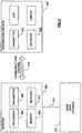
- FIG. 2is an illustrative representation of electronic components of a navigation device 200 according to an example embodiment of the present disclosure, in block component format. It should be noted that the block diagram of the navigation device 200 is not inclusive of all components of the navigation device, but is only representative of many example components.
- the navigation device 200is located within a housing (not shown).
- the housingincludes a processor 210 connected to an input device 220 and a display screen 240.
- the input device 220can include a keyboard device, voice input device, touch panel and/or any other known input device utilised to input information; and the display screen 240 can include any type of display screen such as an LCD display, for example.
- the input device 220 and display screen 240are integrated into an integrated input and display device, including a touchpad or touch screen input so that a user need only touch a portion of the display screen 240 to select one of a plurality of display choices or to activate one of a plurality of virtual buttons.
- the navigation devicemay include an output device 260, for example an audible output device (e.g. a loudspeaker).
- output device 260can produce audible information for a user of the navigation device 200, it is should equally be understood that input device 220 can include a microphone and software for receiving input voice commands as well.
- processor 210is operatively connected to and set to receive input information from input device 220 via a connection 225, and operatively connected to at least one of display screen 240 and output device 260, via output connections 245, to output information thereto. Further, the processor 210 is operably coupled to a memory resource 230 via connection 235 and is further adapted to receive/send information from/to input/output (I/O) ports 270 via connection 275, wherein the I/O port 270 is connectible to an I/O device 280 external to the navigation device 200.
- the memory resource 230includes, for example, a volatile memory, such as a Random Access Memory (RAM) and a non-volatile memory, for example a digital memory, such as a flash memory.
- RAMRandom Access Memory
- non-volatile memoryfor example a digital memory, such as a flash memory.
- the external I/O device 280may include, but is not limited to an external listening device such as an earpiece for example.
- the connection to I/O device 280can further be a wired or wireless connection to any other external device such as a car stereo unit for hands-free operation and/or for voice activated operation for example, for connection to an ear piece or head phones, and/or for connection to a mobile phone for example, wherein the mobile phone connection may be used to establish a data connection between the navigation device 200 and the internet or any other network for example, and/or to establish a connection to a server via the internet or some other network for example.
- FIG. 2further illustrates an operative connection between the processor 210 and an antenna/receiver 250 via connection 255, wherein the antenna/receiver 250 can be a GPS antenna/receiver for example.
- the antenna and receiver designated by reference numeral 250are combined schematically for illustration, but that the antenna and receiver may be separately located components, and that the antenna may be a GPS patch antenna or helical antenna for example.
- the electronic components shown in FIG. 2are powered by power sources (not shown) in a conventional manner.
- power sourcesnot shown
- different configurations of the components shown in FIG. 2are considered to be within the scope of the present application.
- the components shown in FIG. 2may be in communication with one another via wired and/or wireless connections and the like.
- the scope of the navigation device 200 of the present applicationincludes a portable or handheld navigation device 200.
- the portable or handheld navigation device 200 of FIG. 2can be connected or "docked" in a known manner to a vehicle such as a bicycle, a motorbike, a car or a boat for example. Such a navigation device 200 is then removable from the docked location for portable or handheld navigation use.
- the navigation device 200may establish a "mobile" or telecommunications network connection with a server 302 via a mobile device (not shown) (such as a mobile phone, PDA, and/or any device with mobile phone technology) establishing a digital connection (such as a digital connection via known Bluetooth technology for example). Thereafter, through its network service provider, the mobile device can establish a network connection (through the internet for example) with a server 302. As such, a "mobile" network connection is established between the navigation device 200 (which can be, and often times is mobile as it travels alone and/or in a vehicle) and the server 302 to provide a "real-time" or at least very “up to date” gateway for information.
- the establishing of the network connection between the mobile device (via a service provider) and another device such as the server 302, using an internet (such as the World Wide Web) for example,can be done in a known manner. This can include use of TCP/IP layered protocol for example.
- the mobile devicecan utilize any number of communication standards such as CDMA, GSM, WAN, etc.
- an internet connectionmay be utilised which is achieved via data connection, via a mobile phone or mobile phone technology within the navigation device 200 for example.
- an internet connection between the server 302 and the navigation device 200is established. This can be done, for example, through a mobile phone or other mobile device and a GPRS (General Packet Radio Service)-connection (GPRS connection is a highspeed data connection for mobile devices provided by telecom operators; GPRS is a method to connect to the internet).
- GPRSGeneral Packet Radio Service
- the navigation device 200can further complete a data connection with the mobile device, and eventually with the internet and server 302, via existing Bluetooth technology for example, in a known manner, wherein the data protocol can utilize any number of standards, such as the GSRM, the Data Protocol Standard for the GSM standard, for example.
- the data protocolcan utilize any number of standards, such as the GSRM, the Data Protocol Standard for the GSM standard, for example.
- the navigation device 200may include its own mobile phone technology within the navigation device 200 itself (including an antenna for example, or optionally using the internal antenna of the navigation device 200).
- the mobile phone technology within the navigation device 200can include internal components as specified above, and/or can include an insertable card (e.g. Subscriber Identity Module or SIM card), complete with necessary mobile phone technology and/or an antenna for example.
- mobile phone technology within the navigation device 200can similarly establish a network connection between the navigation device 200 and the server 302, via the internet for example, in a manner similar to that of any mobile device.
- a Bluetooth enabled navigation devicemay be used to correctly work with the ever changing spectrum of mobile phone models, manufacturers, etc., model/manufacturer specific settings may be stored on the navigation device 200 for example. The data stored for this information can be updated.
- the navigation device 200is depicted as being in communication with the server 302 via a generic communications channel 318 that can be implemented by any of a number of different arrangements.
- the server 302 and a navigation device 200can communicate when a connection via communications channel 318 is established between the server 302 and the navigation device 200 (noting that such a connection can be a data connection via mobile device, a direct connection via personal computer via the internet, etc.).
- the server 302includes, in addition to other components which may not be illustrated, a processor 304 operatively connected to a memory 306 and further operatively connected, via a wired or wireless connection 314, to a mass data storage device 312.
- the processor 304is further operatively connected to transmitter 308 and receiver 310, to transmit and send information to and from navigation device 200 via communications channel 318.
- the signals sent and receivedmay include data, communication, and/or other propagated signals.
- the transmitter 308 and receiver 310may be selected or designed according to the communications requirement and communication technology used in the communication design for the navigation system 200. Further, it should be noted that the functions of transmitter 308 and receiver 310 may be combined into a signal transceiver.
- Server 302is further connected to (or includes) a mass storage device 312, noting that the mass storage device 312 may be coupled to the server 302 via communication link 314.
- the mass storage device 312contains a store of navigation data and map information, and can again be a separate device from the server 302 or can be incorporated into the server 302.
- the navigation device 200is adapted to communicate with the server 302 through communications channel 318, and includes processor, memory, etc. as previously described with regard to FIG. 2 , as well as transmitter 320 and receiver 322 to send and receive signals and/or data through the communications channel 318, noting that these devices can further be used to communicate with devices other than server 302. Further, the transmitter 320 and receiver 322 are selected or designed according to communication requirements and communication technology used in the communication design for the navigation device 200 and the functions of the transmitter 320 and receiver 322 may be combined into a single transceiver.
- Software stored in server memory 306provides instructions for the processor 304 and allows the server 302 to provide services to the navigation device 200.
- One service provided by the server 302involves processing requests from the navigation device 200 and transmitting navigation data from the mass data storage 312 to the navigation device 200.
- Another service provided by the server 302includes processing the navigation data using various algorithms for a desired application and sending the results of these calculations to the navigation device 200.
- the communication channel 318generically represents the propagating medium or path that connects the navigation device 200 and the server 302.
- Both the server 302 and navigation device 200include a transmitter for transmitting data through the communication channel and a receiver for receiving data that has been transmitted through the communication channel.
- the communication channel 318is not limited to a particular communication technology. Additionally, the communication channel 318 is not limited to a single communication technology; that is, the channel 318 may include several communication links that use a variety of technology. For example, the communication channel 318 can be adapted to provide a path for electrical, optical, and/or electromagnetic communications, etc. As such, the communication channel 318 includes, but is not limited to, one or a combination of the following: electric circuits, electrical conductors such as wires and coaxial cables, fibre optic cables, converters, radio-frequency (RF) waves, the atmosphere, empty space, etc. Furthermore, the communication channel 318 can include intermediate devices such as routers, repeaters, buffers, transmitters, and receivers, for example.
- RFradio-frequency
- the communication channel 318includes telephone and computer networks. Furthermore, the communication channel 318 may be capable of accommodating wireless communication such as radio frequency, microwave frequency, infrared communication, etc. Additionally, the communication channel 318 can accommodate satellite communication.
- the communication signals transmitted through the communication channel 318include, but are not limited to, signals as may be required or desired for given communication technology.
- the signalsmay be adapted to be used in cellular communication technology such as Time Division Multiple Access (TDMA), Frequency Division Multiple Access (FDMA), Code Division Multiple Access (CDMA), Global System for Mobile Communications (GSM), etc.
- TDMATime Division Multiple Access
- FDMAFrequency Division Multiple Access
- CDMACode Division Multiple Access
- GSMGlobal System for Mobile Communications
- Both digital and analogue signalscan be transmitted through the communication channel 318.
- These signalsmay be modulated, encrypted and/or compressed signals as may be desirable for the communication technology.
- the server 302includes a remote server accessible by the navigation device 200 via a wireless channel.
- the server 302may include a network server located on a local area network (LAN), wide area network (WAN), virtual private network (VPN), etc.
- LANlocal area network
- WANwide area network
- VPNvirtual private network
- the server 302may include a personal computer such as a desktop or laptop computer, and the communication channel 318 may be a cable connected between the personal computer and the navigation device 200.
- a personal computermay be connected between the navigation device 200 and the server 302 to establish an internet connection between the server 302 and the navigation device 200.
- a mobile telephone or other handheld devicemay establish a wireless connection to the internet, for connecting the navigation device 200 to the server 302 via the internet.
- the navigation device 200may be provided with information from the server 302 via information downloads which may be periodically updated automatically or upon a user connecting navigation device 200 to the server 302 and/or may be more dynamic upon a more constant or frequent connection being made between the server 302 and navigation device 200 via a wireless mobile connection device and TCP/IP connection for example.
- the processor 304 in the server 302may be used to handle the bulk of the processing needs, however, processor 210 of navigation device 200 can also handle much processing and calculation, oftentimes independent of a connection to a server 302.
- a navigation device 200includes a processor 210, an input device 220, and a display screen 240.
- the input device 220 and display screen 240may be integrated into an integrated input and display device to enable both input of information (via direct input, menu selection, etc.) and display of information through a touch panel screen, for example.
- a touch panel screenfor example.
- Such a screenmay be a touch input LCD screen, for example, as is well known to those of ordinary skill in the art.
- the navigation device 200can also include any additional input device 220 and/or any additional output device 260, such as audio input/output devices for example.
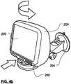
- FIGS. 4a and 4bare perspective views of a navigation device 200.
- the navigation device 200may be a unit that includes an integrated input and display device 290 (a touch panel screen for example) and the other components of FIG. 2 (including but not limited to internal GPS receiver 250, microprocessor 210, a power supply, memory systems 230, etc.).
- the navigation device 200may sit on an arm 292, which itself may be secured to a vehicle dashboard/window/etc. using a suction cup 294.
- This arm 292is one example of a docking station to which the navigation device 200 can be docked.
- the navigation device 200can be docked or otherwise connected to an arm 292 of the docking station by snap connecting the navigation device 292 to the arm 292 for example.
- the navigation device 200may then be rotatable on the arm 292, as shown by the arrow of FIG. 4b .
- a button on the navigation device 200may be pressed, for example.
- Other equally suitable arrangements for coupling and decoupling the navigation device to a docking stationare well known to persons of ordinary skill in the art.
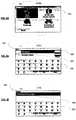
- FIGS. 5a to 5ithere is depicted a series of screenshots from a navigation device 200.
- This navigation device 200has a touch screen interface for displaying information to a user and for accepting input to the device from the user.
- the screenshotsshow an illustrative example embodiment of a destination location input process for a user whose home location has been set to the offices in The Hague of the European Patent Office, and who wishes to navigate to a street address in Amsterdam, The Netherlands for which they know the street name and building number.
- the deviceWhen this user switches on their navigation device 200, the device acquires a GPS fix and calculates (in a known manner) the current location of the navigation device 200. The user is then presented, as shown in FIG. 5a , with a display 340 showing in pseudo three-dimensions the local environment 342 in which the navigation device 200 is determined to be located, and in a region 344 of the display 340 below the local environment a series of control and status messages.
- the navigation device 200By touching the display of the local environment 342, the navigation device 200 switches to display (as shown in FIG. 5b ) a series of virtual buttons 346 by means of which a user can, inter alia, input a destination that they wish to navigate to.
- the navigation device 200switches to display (as shown in FIG. 5c ) a plurality of virtual buttons that are each associated with a different category of selectable destinations.
- the displayshows a "home” button that if pressed would set the destination to the stored home location.
- the "favourite” buttonif pressed, reveals a list of destinations that the user has previously stored in the navigation device 200 and if one of these destinations is then selected the destination for the route to be calculated is set to the selected previously stored destination.
- the "recent destination” buttonif pressed, reveals a list of selectable destinations held in the memory of the navigation device 200 and to which the user has recently navigated. Selection of one of the destinations populating this list would set the destination location for this route to the selected (previously visited) location.
- the "point of interest” buttonif pressed, reveals a number of options by which a user can opt to navigate to any of a plurality of locations, such as cash machines, petrol stations or tourist attractions for example, that have been pre-stored in the device as locations that a user of the device might want to navigate to.
- the "arrow” shaped virtual buttonopens a new menu of additional options, and the "address” button 350 commences a process by which the user can input the street address of the destination that they wish to navigate to.
- this "address” buttonis operated (by touching the button displayed on the touch screen), whereupon (as shown in FIG. 5d ) the user is presented with a series of address input options - in particular for address input by "city centre”, by "postcode”, by "crossing or intersection” (for example a junction of two roads) and by "street and house number”.
- the userknows the street address and house number of the destination and hence selects the "street and house number" virtual button 352 whereupon the user is then presented, as shown in FIG. 5e , a prompt 354 to enter the name of the city that they wish to navigate to, a flag button 356 by which the user can select the country in which the desired city is located, and a virtual keyboard 358 that may be operated by the user, if necessary, to input the name of the destination city.
- the userhas previously navigated to locations in Rijswijk and Amsterdam, and the PND therefore additionally provides the user with a list 360 of selectable cites.
- the user in this instancewishes to navigate to Amsterdam, and on selection of Amsterdam from the list 360 the navigation device 200 displays, as shown in FIG. 5f , a virtual keyboard 362 by means of which a user can input street names, a prompt 364 for entry of a street name 364 and, in this instance, as the user has previously navigated to a street in Amsterdam, a list 366 of selectable streets in Amsterdam.
- the userwishes to return to the street, Rembrandtplein, that they have previously visited and so selects Rembrandtplein from the displayed list 366.
- the navigation device 200displays a smaller virtual keypad 368 and prompts the user, via prompt 370, to enter the number of the house in the selected street and city that they wish to navigate to. If the user has previously navigated to a house number in this street, then that number (as shown in FIG. 5g ) is initially shown. If, as in this instance, the user wishes to navigate to No. 35, Rembrandtplein once again, then the user need only touch a "done" virtual button 372 displayed at the bottom right hand corner of the display. If the user should wish to navigate to a different house number in Rembrandtplein, then all they need do is operate the keypad 368 to input the appropriate house number.
- the useris asked in FIG. 5h , whether they wish to arrive at a particular time. If the user should push the "yes" button, then functionality is invoked that estimates the time required to travel to the destination and advises the user when they should leave (or if they are running late, should have left) their current location in order to arrive at their destination on time. In this instance the user is not concerned about arriving at a particular time and hence selects the "no" virtual button.
- Selecting the "no" button 374causes the navigation device 200 to calculate a route between the current location and the selected destination and to display that route 376, as shown in FIG. 5i , on a relatively low magnification map that shows the entire route.
- the userprovided with a "done” virtual button 378 which they can press to indicate that they are happy with the calculated route, a "find alternative” button 380 that the user can press to cause the navigation device 200 to calculate another route to the selected destination, and a “details” button 382 that a user can press to reveal selectable options for the display of more detailed information concerning the currently displayed route 376.
- the lower part of the displayhas also changed and now displays the name of the street in which the navigation device 200 is currently located, an icon 388 indicating the distance to and type of the next manoeuvre (from the current location of the navigation device 200), and a dynamic display 390 of the distance and time to the selected destination.
- the userthen commences their journey and the navigation device 200 guides the user, in a known manner, by updating the map in accordance with determined changes in navigation device 200 location, and by providing the user with visual and, optionally, audible navigation instructions.
- a method of detecting a bifurcation in a navigable featureincludes first determining a first possible segment and a second possible segment of the navigable feature based on location measurements along the navigable feature, the location measurements representing a heading vector and the location measurements having a higher probability of being on the first possible segment than on the second possible segment; second determining an angle based on the heading vector and a vector between the second possible segment and the heading vector; and detecting a bifurcation based on the angle.
- the example embodiments described belowuse GPS data as an example of sequential location measurements, however, the example embodiments should not be limited thereto.
- Segments in navigation networkssuch as a portion of a road and/or a sidewalk are often referred to as navigable features. Boundaries of these segments, such as centrelines, lanes, curbs, shoulder lines and stop sign lines may be referred to as geometric features.
- GPS measurementsincluding latitudinal and longitudinal coordinates
- location measurementsmay be obtained from any source and are not limited to GPS.
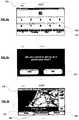
- FIGS. 7a and 8illustrate a method of detecting a bifurcation in a navigable feature according to an example embodiment.
- the method of FIG. 7amay be performed by the navigation 200, for example.
- a servere.g., server 302 may perform the method of FIG. 7a .
- the navigation devicereceives at least one location measurement of the navigation device.
- the location measurementsmay be GPS, accelerometer, compass, wheel speed, radio and/or air pressure measurements, for example.
- the navigation devicedetermines a plurality of possible segments of navigable features where the navigation device is located at S730.
- the possible segmentsmay be determined by any known method of map matching.
- map matchingthe navigation device orders the plurality of possible segments from a most likely possible segment (first possible segment) to a least likely possible segment.
- the navigation devicedetermines a first possible segment and a second possible segment from the plurality of possible segments. The location measurements have a higher probability of being on the first possible segment than on the second possible segment.
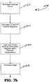
- step S730is shown in greater detail in FIG. 7b .
- the navigation devicedetermines a heading vector based on sensor measurements (e.g., location measurements), previous values of the heading vector and/or map information.
- the heading vectorpoints in a best estimated direction in which the navigation device is travelling. Also, the position of the navigation device is determined.
- the navigation devicedetermines the first and second possible segments by matching the best estimated heading and best estimated location to digitized road representations on a digital map stored in the navigation device.
- the navigation devicedetermines the plurality of possible segments using any known map matching method at S734.
- the navigation devicedetermines the plurality of possible segments based on at least one of position and orientation.
- Each of the plurality of possible segmentshas a rating.
- the navigation devicedetermines first and second possible segments based on the ratings. Each rating represents a likelihood of the navigation device being on the possible segment. Thus, the first possible segment has the highest rating and the second possible segment has the second highest rating.
- the navigation devicemay initially assume that the first possible segment is the correct segment. Therefore, the navigation device may display a position corresponding to the first possible segment while the navigation device is performing the method of FIG. 7a .
- the navigation devicedetermines a vector between the second possible segment and one of the location measurements as a navigation device based location.
- the navigation device based locationmay be the most recently received location measurement, for example.
- the navigation devicedetermines an angle between the heading vector and a vector between the navigation device based location and the second possible segment at S738.
- the navigation devicemay determine the angle by first determining a dot product of the heading vector and the vector between the second possible segment and navigation device based location and then determining the cosine of the angle based on the dot product. The angle is then determined by the cosine value.
- FIG. 8provides an illustration of S730. As shown in FIG. 8 , a bifurcation exists in a navigable feature NV. Based on location measurements, the navigation device determines a heading vector V heading , a first possible segment PS 1 and a second possible segment PS 2 . The navigation device then determines a vector V h-s from one location measurement (a navigation device based location N L ) to the second possible segment PS2. The navigation device then determines an angle ⁇ .
- the navigation devicedetermines whether a bifurcation exists in the navigable feature at S750, as shown in FIG. 7a .
- Step S750is shown in greater detail in FIG. 7c .
- the navigation devicedetermines whether the angle exceeds a threshold at S755.
- the thresholdmay be seventy degrees. However, it should be understood that any threshold may be used.
- the thresholdmay be a constant or may change based on the environment of the route. While step S750 illustrates that the angle should be greater or equal to the threshold, S750 should not be limited thereto. It should be understood that values other than the angle may be used such as the cosine of the angle.
- the navigation devicedetermines that there is no bifurcation at S760. If the angle is greater than or equal to the threshold, then the navigation device determines that there is a bifurcation at S765.
- the navigation deviceBased on whether a bifurcation exists at S750, the navigation device matches a selected route to a map and displays the selected route on the map at S770. For example, the navigation device may display an arrow such as 384 (shown in FIG. 6 ) on the selected route. The position of the displayed selected route corresponds to a position on one of the first and second possible segments.
- Selecting the first possible segment or the second possible segment as the selected routeis based on detecting a bifurcation.
- the selected routeis one of the first and second possible segments. If a bifurcation is not detected, a general route selecting algorithm may be used. For example, the first possible segment may be selected if the angle is less than the threshold. However, if the bifurcation is detected, then a more complex route selecting algorithm may be used. For example, the first or second possible segment may be selected if the angle is greater than or equal to the threshold based on the route selecting algorithm. If a bifurcation is detected, the bifurcation may be marked on the map as a bifurcation and be incorporated into a map database.
- the navigation device 200may utilise any kind of position sensing technology as an alternative to (or indeed in addition to) GPS.
- the navigation devicemay utilise using other global navigation satellite systems such as the European Galileo system. Equally, it is not limited to satellite based but could readily function using ground based beacons or any other kind of system that enables the device to determine its geographic location.
Landscapes
- Engineering & Computer Science (AREA)
- Remote Sensing (AREA)
- Theoretical Computer Science (AREA)
- General Physics & Mathematics (AREA)
- Physics & Mathematics (AREA)
- Radar, Positioning & Navigation (AREA)
- Computer Networks & Wireless Communication (AREA)
- General Engineering & Computer Science (AREA)
- Signal Processing (AREA)
- Human Computer Interaction (AREA)
- Multimedia (AREA)
- Computing Systems (AREA)
- General Health & Medical Sciences (AREA)
- Medical Informatics (AREA)
- Health & Medical Sciences (AREA)
- Business, Economics & Management (AREA)
- General Business, Economics & Management (AREA)
- Automation & Control Theory (AREA)
- Navigation (AREA)
- Information Retrieval, Db Structures And Fs Structures Therefor (AREA)
- Telephone Function (AREA)
Description
- This disclosure generally relates to systems and methods for bifurcation detection. At least some example embodiments relate to portable navigation devices (so-called PNDs).
- In recent years, consumers have been provided with a variety of devices and systems to enable them to locate places on a digital map using GPS (Global Positioning System) signal reception, processing functionality and/or gyroscope values within the devices and systems. The variety of devices and systems used by consumers are in the form of in-vehicle navigation systems that enable drivers to navigate over streets and roads; hand-held devices such as personal digital assistants ("PDAs"), personal navigation devices (PNDs), and cell phones or other types of mobile devices that can do the same; desktop applications, and Internet applications in which users can generate maps showing desired places. The common aspect in all of these and other types of devices and systems is a map database of geographic features, vectors and attributes, and software to access, manipulate and navigate the map database in response to user inputs.
- Generally, localization in bifurcations is difficult for positioning and map matching systems. Small errors in gyroscope measurements and/or tiny miscalibrations cause heading errors that are large enough to result in a wrong location and direction being displayed on a navigation device. In such a case, the position and heading errors are in the range of map incertitudes with a risk for a mismatch. Detecting a bifurcation in such circumstances can help the localization process.
WO 2008/072293 A1 discloses a navigation device having a function for performing route research in prediction of a deviation of a vehicle from a recommended route.- Example embodiments provide methods for bifurcation detection. Positioning systems such as gyroscope and GPS are used to display a position on a correct leg of the bifurcation.
- According to a first aspect of the invention there is provided a method of detecting a bifurcation in a navigable feature as claimed in
claim 1. - According to another aspect of the invention there is provided computer software including one or more software modules operable, when executed in an execution environment, to cause a computer to perform a method as claimed in claim 13.
- According to another aspect of the invention there is provided a navigation device as claimed in claim 14.
- Various aspects of the teachings of the present disclosure, and arrangements embodying those teachings, will hereafter be described by way of illustrative example with reference to the accompanying drawings, in which:
FIG. 1 is a schematic illustration of a Global Positioning System (GPS);FIG. 2 is a schematic illustration of electronic components arranged to provide a navigation device;FIG. 3 is a schematic illustration of the manner in which a navigation device may receive information over a wireless communication channel;FIGS. 4a and4b are illustrative perspective views of a navigation device;FIGS. 5a to 5i are illustrative screenshots from a navigation device for a destination input process;FIG. 6 is an illustrative screenshot from a navigation device depicting a start location for an illustrative calculated route;FIGS. 7a-7c illustrate a method of detecting a bifurcation in a navigable feature according to an example embodiment; andFIG. 8 illustrates an example embodiment of a method of detecting a bifurcation in a navigable feature according to the example embodiment ofFIGS. 7a-7c .- It should be noted that these Figures are intended to illustrate the general characteristics of methods, structure and/or materials utilized in certain example embodiments and to supplement the written description provided below. These drawings are not, however, to scale and may not precisely reflect the precise structural or performance characteristics of any given embodiment, and should not be interpreted as defining or limiting the range of values or properties encompassed by example embodiments. For example, layers, regions and/or structural elements may be reduced or exaggerated for clarity. The use of similar or identical reference numbers in the various drawings is intended to indicate the presence of a similar or identical element or feature.
- Various example embodiments will now be described more fully with reference to the accompanying drawings in which some example embodiments are illustrated.
- Accordingly, while example embodiments are capable of various modifications and alternative forms, embodiments thereof are shown by way of example in the drawings and will herein be described in detail. It should be understood, however, that there is no intent to limit example embodiments to the particular forms disclosed, but on the contrary, example embodiments are to cover all modifications, equivalents, and alternatives falling within the scope of example embodiments. Like numbers refer to like elements throughout the description of the figures.
- It will be understood that, although the terms first, second, etc. may be used herein to describe various elements, these elements should not be limited by these terms. These terms are only used to distinguish one element from another. For example, a first element could be termed a second element, and, similarly, a second element could be termed a first element, without departing from the scope of example embodiments. As used herein, the term "and/or" includes any and all combinations of one or more of the associated listed items.
- It will be understood that when an element is referred to as being "connected" or "coupled" to another element, it can be directly connected or coupled to the other element or intervening elements may be present. In contrast, when an element is referred to as being "directly connected" or "directly coupled" to another element, there are no intervening elements present. Other words used to describe the relationship between elements should be interpreted in a like fashion (e.g., "between" versus "directly between," "adjacent" versus "directly adjacent," etc.).
- The terminology used herein is for the purpose of describing particular embodiments only and is not intended to be limiting of example embodiments. As used herein, the singular forms "a," "an" and "the" are intended to include the plural forms as well, unless the context clearly indicates otherwise. It will be further understood that the terms "comprises," "comprising," "includes" and/or "including," when used herein, specify the presence of stated features, integers, steps, operations, elements and/or components, but do not preclude the presence or addition of one or more other features, integers, steps, operations, elements, components and/or groups thereof.
- It should also be noted that in some alternative implementations, the functions/acts noted may occur out of the order noted in the figures. For example, two figures shown in succession may in fact be executed substantially concurrently or may sometimes be executed in the reverse order, depending upon the functionality/acts involved.
- Unless otherwise defined, all terms (including technical and scientific terms) used herein have the same meaning as commonly understood by one of ordinary skill in the art to which example embodiments belong. It will be further understood that terms, e.g., those defined in commonly used dictionaries, should be interpreted as having a meaning that is consistent with their meaning in the context of the relevant art and will not be interpreted in an idealized or overly formal sense unless expressly so defined herein.
- Portions of example embodiments and corresponding detailed description are presented in terms of software, or algorithms and symbolic representations of operation on data bits within a computer memory. These descriptions and representations are the ones by which those of ordinary skill in the art effectively convey the substance of their work to others of ordinary skill in the art. An algorithm, as the term is used here, and as it is used generally, is conceived to be a self-consistent sequence of steps leading to a desired result. The steps are those requiring physical manipulations of physical quantities. Usually, though not necessarily, these quantities take the form of optical, electrical, or magnetic signals capable of being stored, transferred, combined, compared, and otherwise manipulated. It is convenient at times, principally for reasons of common usage, to refer to these signals as bits, values, elements, symbols, characters, terms, numbers, or the like.
- In the following description, illustrative embodiments will be described with reference to acts and symbolic representations of operations (e.g., in the form of flowcharts) that may be implemented as program modules or functional processes include routines, programs, objects, components, data structures, that perform particular tasks or implement particular abstract data types and may be implemented using existing hardware at existing network elements or control nodes (e.g., a database). Such existing hardware may include one or more Central Processing Units (CPUs), digital signal processors (DSPs), application-specific-integrated-circuits, field programmable gate arrays (FPGAs) computers or the like.
- It should be borne in mind, however, that all of these and similar terms are to be associated with the appropriate physical quantities and are merely convenient labels applied to these quantities. Unless specifically stated otherwise, or as is apparent from the discussion, terms such as "processing" or "computing" or "calculating" or "determining" or "displaying" or the like, refer to the action and processes of a computer system, or similar electronic computing device, that manipulates and transforms data represented as physical, electronic quantities within the computer system's registers and memories into other data similarly represented as physical quantities within the computer system memories or registers or other such information storage, transmission or display devices.
- Note also that the software implemented aspects of example embodiments are typically encoded on some form of computer readable medium or implemented over some type of transmission medium. The computer readable medium may be magnetic (e.g., a floppy disk or a hard drive) or optical (e.g., a compact disk read only memory, or "CD ROM"), and may be read only or random access. Similarly, the transmission medium may be twisted wire pairs, coaxial cable, optical fiber, or some other suitable transmission medium known to the art. Example embodiments are not limited by these aspects of any given implementation.
- Example embodiments of the present disclosure will now be described with particular reference to a PND. It should be remembered, however, that the teachings of the present disclosure are not limited to PNDs but are instead universally applicable to any type of mobile device.
- It follows therefore that in the context of the present application, a navigation device is intended to include (without limitation) any type of route planning and navigation device, irrespective of whether that device is embodied as a PND, mobile telephone or portable digital assistant (PDA) executing route planning and navigation software. The navigation device uses and/or measures its location.
- It will also be apparent from the following that the teachings of the present disclosure even have utility in circumstances where a user is not seeking instructions on how to navigate from one point to another, but merely wishes to be provided with a view of a given location. In such circumstances the "destination" location selected by the user need not have a corresponding start location from which the user wishes to start navigating, and as a consequence references herein to the "destination" location or indeed to a "destination" view should not be interpreted to mean that the generation of a route is essential, that travelling to the "destination" must occur, or indeed that the presence of a destination requires the designation of a corresponding start location.
- With the above provisos in mind,
FIG. 1 illustrates an example view of Global Positioning System (GPS), usable by navigation devices. Such systems are known and are used for a variety of purposes. In general, GPS is a satellite-radio based navigation system capable of determining continuous position, velocity, time, and in some instances direction information for an unlimited number of users. Formerly known as NAVSTAR, the GPS incorporates a plurality of satellites which orbit the earth in extremely precise orbits. Based on these precise orbits, GPS satellites can relay their location to any number of receiving units. - The GPS system is implemented when a device, specially equipped to receive GPS data, begins scanning radio frequencies for GPS satellite signals. Upon receiving a radio signal from a GPS satellite, the device determines the precise location of that satellite via one of a plurality of different conventional methods. The device will continue scanning, in most instances, for signals until it has acquired at least three different satellite signals (noting that position is not normally, but can be determined, with only two signals using other triangulation techniques). Implementing geometric triangulation, the receiver utilizes the three known positions to determine its own two-dimensional position relative to the satellites. This can be done in a known manner. Additionally, acquiring a fourth satellite signal will allow the receiving device to calculate its three dimensional position by the same geometrical calculation in a known manner. The position and velocity data can be updated in real time on a continuous basis by an unlimited number of users.
- As shown in
FIG. 1 , the GPS system is denoted generally byreference numeral 100. A plurality ofsatellites 120 are in orbit about theearth 124. The orbit of eachsatellite 120 is not necessarily synchronous with the orbits ofother satellites 120 and, in fact, is likely asynchronous. AGPS receiver 140 is shown receiving spread spectrum GPS satellite signals 160 from thevarious satellites 120. - The spread spectrum signals 160, continuously transmitted from each
satellite 120, utilize a highly accurate frequency standard accomplished with an extremely accurate atomic clock. Eachsatellite 120, as part of itsdata signal transmission 160, transmits a data stream indicative of thatparticular satellite 120. It is appreciated by those skilled in the relevant art that theGPS receiver device 140 generally acquires spread spectrum GPS satellite signals 160 from at least threesatellites 120 for theGPS receiver device 140 to calculate its two-dimensional position by triangulation. Acquisition of an additional signal, resulting insignals 160 from a total of foursatellites 120, permits theGPS receiver device 140 to calculate its three-dimensional position in a known manner. FIG. 2 is an illustrative representation of electronic components of anavigation device 200 according to an example embodiment of the present disclosure, in block component format. It should be noted that the block diagram of thenavigation device 200 is not inclusive of all components of the navigation device, but is only representative of many example components.- The
navigation device 200 is located within a housing (not shown). The housing includes aprocessor 210 connected to aninput device 220 and adisplay screen 240. Theinput device 220 can include a keyboard device, voice input device, touch panel and/or any other known input device utilised to input information; and thedisplay screen 240 can include any type of display screen such as an LCD display, for example. In an example arrangement, theinput device 220 anddisplay screen 240 are integrated into an integrated input and display device, including a touchpad or touch screen input so that a user need only touch a portion of thedisplay screen 240 to select one of a plurality of display choices or to activate one of a plurality of virtual buttons. - The navigation device may include an
output device 260, for example an audible output device (e.g. a loudspeaker). Asoutput device 260 can produce audible information for a user of thenavigation device 200, it is should equally be understood thatinput device 220 can include a microphone and software for receiving input voice commands as well. - In the
navigation device 200,processor 210 is operatively connected to and set to receive input information frominput device 220 via aconnection 225, and operatively connected to at least one ofdisplay screen 240 andoutput device 260, viaoutput connections 245, to output information thereto. Further, theprocessor 210 is operably coupled to amemory resource 230 viaconnection 235 and is further adapted to receive/send information from/to input/output (I/O)ports 270 viaconnection 275, wherein the I/O port 270 is connectible to an I/O device 280 external to thenavigation device 200. Thememory resource 230 includes, for example, a volatile memory, such as a Random Access Memory (RAM) and a non-volatile memory, for example a digital memory, such as a flash memory. The external I/O device 280 may include, but is not limited to an external listening device such as an earpiece for example. The connection to I/O device 280 can further be a wired or wireless connection to any other external device such as a car stereo unit for hands-free operation and/or for voice activated operation for example, for connection to an ear piece or head phones, and/or for connection to a mobile phone for example, wherein the mobile phone connection may be used to establish a data connection between thenavigation device 200 and the internet or any other network for example, and/or to establish a connection to a server via the internet or some other network for example. FIG. 2 further illustrates an operative connection between theprocessor 210 and an antenna/receiver 250 viaconnection 255, wherein the antenna/receiver 250 can be a GPS antenna/receiver for example. It will be understood that the antenna and receiver designated byreference numeral 250 are combined schematically for illustration, but that the antenna and receiver may be separately located components, and that the antenna may be a GPS patch antenna or helical antenna for example.- Further, it will be understood by one of ordinary skill in the art that the electronic components shown in
FIG. 2 are powered by power sources (not shown) in a conventional manner. As will be understood by one of ordinary skill in the art, different configurations of the components shown inFIG. 2 are considered to be within the scope of the present application. For example, the components shown inFIG. 2 may be in communication with one another via wired and/or wireless connections and the like. Thus, the scope of thenavigation device 200 of the present application includes a portable orhandheld navigation device 200. - In addition, the portable or
handheld navigation device 200 ofFIG. 2 can be connected or "docked" in a known manner to a vehicle such as a bicycle, a motorbike, a car or a boat for example. Such anavigation device 200 is then removable from the docked location for portable or handheld navigation use. - Referring now to
FIG. 3 , thenavigation device 200 may establish a "mobile" or telecommunications network connection with aserver 302 via a mobile device (not shown) (such as a mobile phone, PDA, and/or any device with mobile phone technology) establishing a digital connection (such as a digital connection via known Bluetooth technology for example). Thereafter, through its network service provider, the mobile device can establish a network connection (through the internet for example) with aserver 302. As such, a "mobile" network connection is established between the navigation device 200 (which can be, and often times is mobile as it travels alone and/or in a vehicle) and theserver 302 to provide a "real-time" or at least very "up to date" gateway for information. - The establishing of the network connection between the mobile device (via a service provider) and another device such as the
server 302, using an internet (such as the World Wide Web) for example, can be done in a known manner. This can include use of TCP/IP layered protocol for example. The mobile device can utilize any number of communication standards such as CDMA, GSM, WAN, etc. - As such, an internet connection may be utilised which is achieved via data connection, via a mobile phone or mobile phone technology within the
navigation device 200 for example. For this connection, an internet connection between theserver 302 and thenavigation device 200 is established. This can be done, for example, through a mobile phone or other mobile device and a GPRS (General Packet Radio Service)-connection (GPRS connection is a highspeed data connection for mobile devices provided by telecom operators; GPRS is a method to connect to the internet). - The
navigation device 200 can further complete a data connection with the mobile device, and eventually with the internet andserver 302, via existing Bluetooth technology for example, in a known manner, wherein the data protocol can utilize any number of standards, such as the GSRM, the Data Protocol Standard for the GSM standard, for example. - The
navigation device 200 may include its own mobile phone technology within thenavigation device 200 itself (including an antenna for example, or optionally using the internal antenna of the navigation device 200). The mobile phone technology within thenavigation device 200 can include internal components as specified above, and/or can include an insertable card (e.g. Subscriber Identity Module or SIM card), complete with necessary mobile phone technology and/or an antenna for example. As such, mobile phone technology within thenavigation device 200 can similarly establish a network connection between thenavigation device 200 and theserver 302, via the internet for example, in a manner similar to that of any mobile device. - For GRPS phone settings, a Bluetooth enabled navigation device may be used to correctly work with the ever changing spectrum of mobile phone models, manufacturers, etc., model/manufacturer specific settings may be stored on the
navigation device 200 for example. The data stored for this information can be updated. - In
FIG. 3 thenavigation device 200 is depicted as being in communication with theserver 302 via ageneric communications channel 318 that can be implemented by any of a number of different arrangements. Theserver 302 and anavigation device 200 can communicate when a connection viacommunications channel 318 is established between theserver 302 and the navigation device 200 (noting that such a connection can be a data connection via mobile device, a direct connection via personal computer via the internet, etc.). - The
server 302 includes, in addition to other components which may not be illustrated, aprocessor 304 operatively connected to amemory 306 and further operatively connected, via a wired orwireless connection 314, to a massdata storage device 312. Theprocessor 304 is further operatively connected totransmitter 308 andreceiver 310, to transmit and send information to and fromnavigation device 200 viacommunications channel 318. The signals sent and received may include data, communication, and/or other propagated signals. Thetransmitter 308 andreceiver 310 may be selected or designed according to the communications requirement and communication technology used in the communication design for thenavigation system 200. Further, it should be noted that the functions oftransmitter 308 andreceiver 310 may be combined into a signal transceiver. Server 302 is further connected to (or includes) amass storage device 312, noting that themass storage device 312 may be coupled to theserver 302 viacommunication link 314. Themass storage device 312 contains a store of navigation data and map information, and can again be a separate device from theserver 302 or can be incorporated into theserver 302.- The
navigation device 200 is adapted to communicate with theserver 302 throughcommunications channel 318, and includes processor, memory, etc. as previously described with regard toFIG. 2 , as well astransmitter 320 andreceiver 322 to send and receive signals and/or data through thecommunications channel 318, noting that these devices can further be used to communicate with devices other thanserver 302. Further, thetransmitter 320 andreceiver 322 are selected or designed according to communication requirements and communication technology used in the communication design for thenavigation device 200 and the functions of thetransmitter 320 andreceiver 322 may be combined into a single transceiver. - Software stored in
server memory 306 provides instructions for theprocessor 304 and allows theserver 302 to provide services to thenavigation device 200. One service provided by theserver 302 involves processing requests from thenavigation device 200 and transmitting navigation data from themass data storage 312 to thenavigation device 200. Another service provided by theserver 302 includes processing the navigation data using various algorithms for a desired application and sending the results of these calculations to thenavigation device 200. - The
communication channel 318 generically represents the propagating medium or path that connects thenavigation device 200 and theserver 302. Both theserver 302 andnavigation device 200 include a transmitter for transmitting data through the communication channel and a receiver for receiving data that has been transmitted through the communication channel. - The
communication channel 318 is not limited to a particular communication technology. Additionally, thecommunication channel 318 is not limited to a single communication technology; that is, thechannel 318 may include several communication links that use a variety of technology. For example, thecommunication channel 318 can be adapted to provide a path for electrical, optical, and/or electromagnetic communications, etc. As such, thecommunication channel 318 includes, but is not limited to, one or a combination of the following: electric circuits, electrical conductors such as wires and coaxial cables, fibre optic cables, converters, radio-frequency (RF) waves, the atmosphere, empty space, etc. Furthermore, thecommunication channel 318 can include intermediate devices such as routers, repeaters, buffers, transmitters, and receivers, for example. - In one illustrative arrangement, the
communication channel 318 includes telephone and computer networks. Furthermore, thecommunication channel 318 may be capable of accommodating wireless communication such as radio frequency, microwave frequency, infrared communication, etc. Additionally, thecommunication channel 318 can accommodate satellite communication. - The communication signals transmitted through the
communication channel 318 include, but are not limited to, signals as may be required or desired for given communication technology. For example, the signals may be adapted to be used in cellular communication technology such as Time Division Multiple Access (TDMA), Frequency Division Multiple Access (FDMA), Code Division Multiple Access (CDMA), Global System for Mobile Communications (GSM), etc. Both digital and analogue signals can be transmitted through thecommunication channel 318. These signals may be modulated, encrypted and/or compressed signals as may be desirable for the communication technology. - The
server 302 includes a remote server accessible by thenavigation device 200 via a wireless channel. Theserver 302 may include a network server located on a local area network (LAN), wide area network (WAN), virtual private network (VPN), etc. - The
server 302 may include a personal computer such as a desktop or laptop computer, and thecommunication channel 318 may be a cable connected between the personal computer and thenavigation device 200. Alternatively, a personal computer may be connected between thenavigation device 200 and theserver 302 to establish an internet connection between theserver 302 and thenavigation device 200. Alternatively, a mobile telephone or other handheld device may establish a wireless connection to the internet, for connecting thenavigation device 200 to theserver 302 via the internet. - The
navigation device 200 may be provided with information from theserver 302 via information downloads which may be periodically updated automatically or upon a user connectingnavigation device 200 to theserver 302 and/or may be more dynamic upon a more constant or frequent connection being made between theserver 302 andnavigation device 200 via a wireless mobile connection device and TCP/IP connection for example. For many dynamic calculations, theprocessor 304 in theserver 302 may be used to handle the bulk of the processing needs, however,processor 210 ofnavigation device 200 can also handle much processing and calculation, oftentimes independent of a connection to aserver 302. - As indicated above in
FIG. 2 , anavigation device 200 includes aprocessor 210, aninput device 220, and adisplay screen 240. Theinput device 220 anddisplay screen 240 may be integrated into an integrated input and display device to enable both input of information (via direct input, menu selection, etc.) and display of information through a touch panel screen, for example. Such a screen may be a touch input LCD screen, for example, as is well known to those of ordinary skill in the art. Further, thenavigation device 200 can also include anyadditional input device 220 and/or anyadditional output device 260, such as audio input/output devices for example. FIGS. 4a and4b are perspective views of anavigation device 200. As shown inFIG. 4a , thenavigation device 200 may be a unit that includes an integrated input and display device 290 (a touch panel screen for example) and the other components ofFIG. 2 (including but not limited tointernal GPS receiver 250,microprocessor 210, a power supply,memory systems 230, etc.).- The
navigation device 200 may sit on anarm 292, which itself may be secured to a vehicle dashboard/window/etc. using asuction cup 294. Thisarm 292 is one example of a docking station to which thenavigation device 200 can be docked. - As shown in
FIG. 4b , thenavigation device 200 can be docked or otherwise connected to anarm 292 of the docking station by snap connecting thenavigation device 292 to thearm 292 for example. Thenavigation device 200 may then be rotatable on thearm 292, as shown by the arrow ofFIG. 4b . To release the connection between thenavigation device 200 and the docking station, a button on thenavigation device 200 may be pressed, for example. Other equally suitable arrangements for coupling and decoupling the navigation device to a docking station are well known to persons of ordinary skill in the art. - Referring now to
FIGS. 5a to 5i there is depicted a series of screenshots from anavigation device 200. Thisnavigation device 200 has a touch screen interface for displaying information to a user and for accepting input to the device from the user. The screenshots show an illustrative example embodiment of a destination location input process for a user whose home location has been set to the offices in The Hague of the European Patent Office, and who wishes to navigate to a street address in Amsterdam, The Netherlands for which they know the street name and building number. - When this user switches on their
navigation device 200, the device acquires a GPS fix and calculates (in a known manner) the current location of thenavigation device 200. The user is then presented, as shown inFIG. 5a , with adisplay 340 showing in pseudo three-dimensions thelocal environment 342 in which thenavigation device 200 is determined to be located, and in aregion 344 of thedisplay 340 below the local environment a series of control and status messages. - By touching the display of the
local environment 342, thenavigation device 200 switches to display (as shown inFIG. 5b ) a series ofvirtual buttons 346 by means of which a user can, inter alia, input a destination that they wish to navigate to. - By touching the "navigate to"
virtual button 348, thenavigation device 200 switches to display (as shown inFIG. 5c ) a plurality of virtual buttons that are each associated with a different category of selectable destinations. In this instance, the display shows a "home" button that if pressed would set the destination to the stored home location. However, in this instance as the user is already at their home location (namely the EPO's offices in the Hague) selecting this option would not cause a route to be generated. The "favourite" button, if pressed, reveals a list of destinations that the user has previously stored in thenavigation device 200 and if one of these destinations is then selected the destination for the route to be calculated is set to the selected previously stored destination. The "recent destination" button, if pressed, reveals a list of selectable destinations held in the memory of thenavigation device 200 and to which the user has recently navigated. Selection of one of the destinations populating this list would set the destination location for this route to the selected (previously visited) location. The "point of interest" button, if pressed, reveals a number of options by which a user can opt to navigate to any of a plurality of locations, such as cash machines, petrol stations or tourist attractions for example, that have been pre-stored in the device as locations that a user of the device might want to navigate to. The "arrow" shaped virtual button opens a new menu of additional options, and the "address"button 350 commences a process by which the user can input the street address of the destination that they wish to navigate to. - Since the user, in this example, knows the street address of the destination that they wish to navigate to, it is assumed that this "address" button is operated (by touching the button displayed on the touch screen), whereupon (as shown in
FIG. 5d ) the user is presented with a series of address input options - in particular for address input by "city centre", by "postcode", by "crossing or intersection" (for example a junction of two roads) and by "street and house number". - In this example the user knows the street address and house number of the destination and hence selects the "street and house number"
virtual button 352 whereupon the user is then presented, as shown inFIG. 5e , a prompt 354 to enter the name of the city that they wish to navigate to, aflag button 356 by which the user can select the country in which the desired city is located, and avirtual keyboard 358 that may be operated by the user, if necessary, to input the name of the destination city. In this instance the user has previously navigated to locations in Rijswijk and Amsterdam, and the PND therefore additionally provides the user with alist 360 of selectable cites. - The user in this instance wishes to navigate to Amsterdam, and on selection of Amsterdam from the
list 360 thenavigation device 200 displays, as shown inFIG. 5f , avirtual keyboard 362 by means of which a user can input street names, a prompt 364 for entry of astreet name 364 and, in this instance, as the user has previously navigated to a street in Amsterdam, alist 366 of selectable streets in Amsterdam. - In this example the user wishes to return to the street, Rembrandtplein, that they have previously visited and so selects Rembrandtplein from the displayed
list 366. - Once a street has been selected, the
navigation device 200 then displays a smallervirtual keypad 368 and prompts the user, viaprompt 370, to enter the number of the house in the selected street and city that they wish to navigate to. If the user has previously navigated to a house number in this street, then that number (as shown inFIG. 5g ) is initially shown. If, as in this instance, the user wishes to navigate to No. 35, Rembrandtplein once again, then the user need only touch a "done"virtual button 372 displayed at the bottom right hand corner of the display. If the user should wish to navigate to a different house number in Rembrandtplein, then all they need do is operate thekeypad 368 to input the appropriate house number. - Once the house number has been input, the user is asked in
FIG. 5h , whether they wish to arrive at a particular time. If the user should push the "yes" button, then functionality is invoked that estimates the time required to travel to the destination and advises the user when they should leave (or if they are running late, should have left) their current location in order to arrive at their destination on time. In this instance the user is not concerned about arriving at a particular time and hence selects the "no" virtual button. - Selecting the "no"
button 374 causes thenavigation device 200 to calculate a route between the current location and the selected destination and to display thatroute 376, as shown inFIG. 5i , on a relatively low magnification map that shows the entire route. The user provided with a "done"virtual button 378 which they can press to indicate that they are happy with the calculated route, a "find alternative"button 380 that the user can press to cause thenavigation device 200 to calculate another route to the selected destination, and a "details"button 382 that a user can press to reveal selectable options for the display of more detailed information concerning the currently displayedroute 376. - In this instance it is assumed that the user is happy with the displayed route, and once the "done"
button 378 has been pressed the user is presented, as shown inFIG. 6 , with a pseudo three-dimensional view of the current, start, location for thenavigation device 200. The display depicted inFIG. 6 is similar to that shown inFIG. 5a except that the displayedlocal environment 342 now includes astart location flag 384 and awaypoint indicator 386 indicating the next manoeuvre (in this instance, a left hand turn). The lower part of the display has also changed and now displays the name of the street in which thenavigation device 200 is currently located, anicon 388 indicating the distance to and type of the next manoeuvre (from the current location of the navigation device 200), and adynamic display 390 of the distance and time to the selected destination. - The user then commences their journey and the
navigation device 200 guides the user, in a known manner, by updating the map in accordance with determined changes innavigation device 200 location, and by providing the user with visual and, optionally, audible navigation instructions. - In at least one example embodiment, a method of detecting a bifurcation in a navigable feature includes first determining a first possible segment and a second possible segment of the navigable feature based on location measurements along the navigable feature, the location measurements representing a heading vector and the location measurements having a higher probability of being on the first possible segment than on the second possible segment; second determining an angle based on the heading vector and a vector between the second possible segment and the heading vector; and detecting a bifurcation based on the angle. The example embodiments described below use GPS data as an example of sequential location measurements, however, the example embodiments should not be limited thereto.
- Segments in navigation networks, such as a portion of a road and/or a sidewalk are often referred to as navigable features. Boundaries of these segments, such as centrelines, lanes, curbs, shoulder lines and stop sign lines may be referred to as geometric features.
- Moreover, while example embodiments described below utilize GPS measurements (trace points) including latitudinal and longitudinal coordinates as location measurements, it should be understood that location measurements may be obtained from any source and are not limited to GPS.
FIGS. 7a and8 illustrate a method of detecting a bifurcation in a navigable feature according to an example embodiment. The method ofFIG. 7a may be performed by thenavigation 200, for example. However, it should be understood that example embodiments are not limited thereto. For example, a server (e.g., server 302) may perform the method ofFIG. 7a .- At S710, the navigation device receives at least one location measurement of the navigation device. The location measurements may be GPS, accelerometer, compass, wheel speed, radio and/or air pressure measurements, for example.
- Based on the received location measurements, the navigation device determines a plurality of possible segments of navigable features where the navigation device is located at S730. The possible segments may be determined by any known method of map matching. Using map matching, the navigation device orders the plurality of possible segments from a most likely possible segment (first possible segment) to a least likely possible segment. The navigation device determines a first possible segment and a second possible segment from the plurality of possible segments. The location measurements have a higher probability of being on the first possible segment than on the second possible segment.
- An example of step S730 is shown in greater detail in
FIG. 7b . At S732, the navigation device determines a heading vector based on sensor measurements (e.g., location measurements), previous values of the heading vector and/or map information. The heading vector points in a best estimated direction in which the navigation device is travelling. Also, the position of the navigation device is determined. The navigation device determines the first and second possible segments by matching the best estimated heading and best estimated location to digitized road representations on a digital map stored in the navigation device. - Based on the heading vector and the position, the navigation device determines the plurality of possible segments using any known map matching method at S734. The navigation device determines the plurality of possible segments based on at least one of position and orientation. Each of the plurality of possible segments has a rating. From the plurality of possible segments, the navigation device determines first and second possible segments based on the ratings. Each rating represents a likelihood of the navigation device being on the possible segment. Thus, the first possible segment has the highest rating and the second possible segment has the second highest rating.
- The navigation device may initially assume that the first possible segment is the correct segment. Therefore, the navigation device may display a position corresponding to the first possible segment while the navigation device is performing the method of
FIG. 7a . - At S736, the navigation device determines a vector between the second possible segment and one of the location measurements as a navigation device based location. The navigation device based location may be the most recently received location measurement, for example.
- The navigation device then determines an angle between the heading vector and a vector between the navigation device based location and the second possible segment at S738. The navigation device may determine the angle by first determining a dot product of the heading vector and the vector between the second possible segment and navigation device based location and then determining the cosine of the angle based on the dot product. The angle is then determined by the cosine value.
FIG. 8 provides an illustration of S730. As shown inFIG. 8 , a bifurcation exists in a navigable feature NV. Based on location measurements, the navigation device determines a heading vector Vheading, a first possible segment PS1 and a second possible segment PS2. The navigation device then determines a vector Vh-s from one location measurement (a navigation device based location NL) to the second possible segment PS2. The navigation device then determines an angle θ.- Once the navigation device determines the angle at S738, the navigation device determines whether a bifurcation exists in the navigable feature at S750, as shown in
FIG. 7a . - Step S750 is shown in greater detail in
FIG. 7c . As shown, the navigation device determines whether the angle exceeds a threshold at S755. For example, the threshold may be seventy degrees. However, it should be understood that any threshold may be used. The threshold may be a constant or may change based on the environment of the route. While step S750 illustrates that the angle should be greater or equal to the threshold, S750 should not be limited thereto. It should be understood that values other than the angle may be used such as the cosine of the angle. - If the angle is not greater than or equal to the threshold, then the navigation device determines that there is no bifurcation at S760. If the angle is greater than or equal to the threshold, then the navigation device determines that there is a bifurcation at S765.
- Based on whether a bifurcation exists at S750, the navigation device matches a selected route to a map and displays the selected route on the map at S770. For example, the navigation device may display an arrow such as 384 (shown in
FIG. 6 ) on the selected route. The position of the displayed selected route corresponds to a position on one of the first and second possible segments. - Selecting the first possible segment or the second possible segment as the selected route is based on detecting a bifurcation. The selected route is one of the first and second possible segments. If a bifurcation is not detected, a general route selecting algorithm may used. For example, the first possible segment may be selected if the angle is less than the threshold. However, if the bifurcation is detected, then a more complex route selecting algorithm may be used. For example, the first or second possible segment may be selected if the angle is greater than or equal to the threshold based on the route selecting algorithm. If a bifurcation is detected, the bifurcation may be marked on the map as a bifurcation and be incorporated into a map database.
- It will also be appreciated that whilst various aspects and embodiments of the present disclosure have heretofore been described, the scope of the present disclosure is not limited to the particular arrangements set out herein and instead extends to encompass all arrangements, and modifications and alterations thereto, which fall within the scope of the appended claims.
- For example, whilst embodiments described in the foregoing detailed description refer to GPS, it should be noted that the
navigation device 200 may utilise any kind of position sensing technology as an alternative to (or indeed in addition to) GPS. For example the navigation device may utilise using other global navigation satellite systems such as the European Galileo system. Equally, it is not limited to satellite based but could readily function using ground based beacons or any other kind of system that enables the device to determine its geographic location. - It will also be well understood by persons of ordinary skill in the art that whilst the example embodiment implements certain functionality by means of software, that functionality could equally be implemented solely in hardware (for example by way of one or more ASICs (application specific integrated circuit)) or indeed by a mix of hardware and software. As such, the scope of the present disclosure should not be interpreted as being limited only to being implemented in software.
Claims (14)
- A method of detecting a bifurcation in a navigable feature of a navigation network, the navigation network being represented by segments of a digital map, the method comprising:receiving (S710) location measurements of a navigation device along the navigable feature, the location measurements representing a heading vector (Vheading);first determining (S730) a first possible segment (PS1) and a second possible segment (PS2) of the digital map based on the location measurements, the location measurements having a higher probability of being on the first possible segment than on the second possible segment;second determining (S730) an angle (θ) based on the heading vector (Vheading) and a vector (Vh·s) between the second possible segment (PS2) and one of the location measurements;detecting (S750) a bifurcation based on the angle (θ); andselecting the first possible segment (PS1) or the second possible segment (PS2) as the segment of the location measurements based on the detecting (S750).
- The method of claim 1, wherein the second determining (S730) includes:determining a navigation device based location (NL) based on the location measurements; anddetermining the vector between the second possible segment and the heading vector, the vector (Vh·s) between the second possible segment (PS2) and the one of the location measurements is a vector (Vh·s) from the navigation device based location (NL) to the second possible segment (PS2).
- The method of claim 1 or 2, further comprising:displaying a position on a navigation device (200), the position on the navigation device (200) corresponding to the selected segment of the location measurements.
- The method of any preceding claim, wherein the selecting includes a first route selecting algorithm selecting the first possible segment (PS1) if the angle (θ) is less than 70 degrees.
- The method of any preceding claim, wherein the selecting includes a second route selecting algorithm selecting the second possible segment (PS2) if the angle (θ) is greater than 70 degrees.
- The method of any preceding claim, wherein the detecting detects a bifurcation if the angle (θ) is greater than a threshold.
- The method of any preceding claim, wherein the second determining includes:determining a dot product of the heading vector (Vheading) and the vector (Vh·s) between the second possible segment (PS2) and one of the location measurements; anddetermining a cosine of the angle (θ) based on the dot product.
- The method of any preceding claim, wherein the first determining (S730) includes:matching the location measurements to at least one position on the digital map; andmatching the location measurements to an orientation on the map, the position and orientation representing the heading vector (Vheading).
- The method of claim 8, wherein the first determining (S730) includes determining a plurality of possible segments based on the at least one position and the orientation, each of the plurality of possible segments having a rating, wherein the first possible segment (PS1) has the highest rating and the second possible segment (PS2) has the second highest rating.
- The method of any preceding claim, wherein the navigable feature (NV) includes at least one of a same road, a same path, a same highway and a same transportation segment.
- The method of any preceding claim, wherein the first determining (S730) determines the first possible segment (PS1) and the second possible segment (PS2) of the digital map based on the location measurements and map data.
- A computer readable medium including program segments for, when executed on a computer, causing the computer to implement the method of any preceding claim.
- Computer software comprising one or more software modules operable, when executed in an execution environment, to cause a computer to implement the method of any one of claims 1 to 11.
- A navigation device (200) comprising a processor (210) configured to:receive (S710) location measurements of a navigation device along a navigable feature of a navigation network, the navigation network being represented by segments of a digital map, the location measurements representing a heading vector (Vheading);determine (S730) a first possible segment (PS1) and a second possible segment (PS2) of the digital map based on the location measurements, the location measurements having a higher probability of being on the first possible segment than on the second possible segment;determine (S730) an angle (θ) based on the heading vector (Vheading) and a vector (Vh·s) between the second possible segment (PS2) and one of the location measurements;detect (S750) a bifurcation based on the angle (θ); andselect the first possible segment (PS1) or the second possible segment (PS2) as the segment of the location measurements based on the detecting (S750).
Applications Claiming Priority (2)
| Application Number | Priority Date | Filing Date | Title |
|---|---|---|---|
| US24025309P | 2009-09-07 | 2009-09-07 | |
| PCT/IB2010/002406WO2011027224A1 (en) | 2009-09-07 | 2010-09-06 | Systems and methods for detecting bifurcations |
Publications (2)
| Publication Number | Publication Date |
|---|---|
| EP2475962A1 EP2475962A1 (en) | 2012-07-18 |
| EP2475962B1true EP2475962B1 (en) | 2017-11-08 |
Family
ID=42153919
Family Applications (2)
| Application Number | Title | Priority Date | Filing Date |
|---|---|---|---|
| EP10723555AWithdrawnEP2476049A1 (en) | 2009-09-07 | 2010-05-19 | Data storage access device |
| EP10775882.3AActiveEP2475962B1 (en) | 2009-09-07 | 2010-09-06 | Systems and methods for detecting bifurcations |
Family Applications Before (1)
| Application Number | Title | Priority Date | Filing Date |
|---|---|---|---|
| EP10723555AWithdrawnEP2476049A1 (en) | 2009-09-07 | 2010-05-19 | Data storage access device |
Country Status (4)
| Country | Link |
|---|---|
| US (4) | US8793033B2 (en) |
| EP (2) | EP2476049A1 (en) |
| TW (4) | TW201113506A (en) |
| WO (7) | WO2011026530A1 (en) |
Families Citing this family (47)
| Publication number | Priority date | Publication date | Assignee | Title |
|---|---|---|---|---|
| CN103370601B (en)* | 2011-02-18 | 2018-01-23 | 索尼移动通信株式会社 | The system and method for determining height above sea level |
| ITTO20110686A1 (en)* | 2011-07-28 | 2013-01-29 | Sisvel Technology Srl | METHOD TO GUARANTEE THE CONTINUITY OF SERVICE OF A PERSONAL NAVIGATION AND RELATIVE DEVICE |
| US9043480B2 (en) | 2011-10-11 | 2015-05-26 | Citrix Systems, Inc. | Policy-based application management |
| US9137262B2 (en) | 2011-10-11 | 2015-09-15 | Citrix Systems, Inc. | Providing secure mobile device access to enterprise resources using application tunnels |
| US20140032733A1 (en) | 2011-10-11 | 2014-01-30 | Citrix Systems, Inc. | Policy-Based Application Management |
| US9215225B2 (en) | 2013-03-29 | 2015-12-15 | Citrix Systems, Inc. | Mobile device locking with context |
| US9280377B2 (en) | 2013-03-29 | 2016-03-08 | Citrix Systems, Inc. | Application with multiple operation modes |
| US9400183B1 (en) | 2011-11-10 | 2016-07-26 | Google Inc. | Method and apparatus to transition between levels using warp zones |
| US9449169B2 (en)* | 2012-03-26 | 2016-09-20 | Vmware, Inc. | Block storage virtualization on commodity secure digital cards |
| US20140108558A1 (en) | 2012-10-12 | 2014-04-17 | Citrix Systems, Inc. | Application Management Framework for Secure Data Sharing in an Orchestration Framework for Connected Devices |
| US9516022B2 (en) | 2012-10-14 | 2016-12-06 | Getgo, Inc. | Automated meeting room |
| US8910239B2 (en) | 2012-10-15 | 2014-12-09 | Citrix Systems, Inc. | Providing virtualized private network tunnels |
| US20140109176A1 (en) | 2012-10-15 | 2014-04-17 | Citrix Systems, Inc. | Configuring and providing profiles that manage execution of mobile applications |
| US20140108793A1 (en) | 2012-10-16 | 2014-04-17 | Citrix Systems, Inc. | Controlling mobile device access to secure data |
| US9971585B2 (en) | 2012-10-16 | 2018-05-15 | Citrix Systems, Inc. | Wrapping unmanaged applications on a mobile device |
| US9606774B2 (en) | 2012-10-16 | 2017-03-28 | Citrix Systems, Inc. | Wrapping an application with field-programmable business logic |
| CN104854561B (en) | 2012-10-16 | 2018-05-11 | 思杰系统有限公司 | Application wrapper for application management framework |
| US9424267B2 (en)* | 2013-01-02 | 2016-08-23 | Oracle International Corporation | Compression and deduplication layered driver |
| US9104893B2 (en) | 2013-03-04 | 2015-08-11 | Microsoft Technology Licensing, Llc | Rule based access for removable storage |
| US9455886B2 (en) | 2013-03-29 | 2016-09-27 | Citrix Systems, Inc. | Providing mobile device management functionalities |
| US9413736B2 (en) | 2013-03-29 | 2016-08-09 | Citrix Systems, Inc. | Providing an enterprise application store |
| US9355223B2 (en) | 2013-03-29 | 2016-05-31 | Citrix Systems, Inc. | Providing a managed browser |
| US10284627B2 (en) | 2013-03-29 | 2019-05-07 | Citrix Systems, Inc. | Data management for an application with multiple operation modes |
| US9985850B2 (en) | 2013-03-29 | 2018-05-29 | Citrix Systems, Inc. | Providing mobile device management functionalities |
| US9188445B2 (en)* | 2013-05-21 | 2015-11-17 | Honda Motor Co., Ltd. | System and method for storing and recalling location data |
| US9858290B1 (en)* | 2013-06-27 | 2018-01-02 | EMC IP Holding Company LLC | Cluster file system with a fuse file system interface |
| CN103512562A (en)* | 2013-09-24 | 2014-01-15 | 上海海洋大学 | Automatic monitoring and early-warning system for offshore area environment based on Arduino |
| TWI571715B (en)* | 2013-10-22 | 2017-02-21 | 光寶電子(廣州)有限公司 | Control device with automatically adjusting function |
| US9639978B2 (en)* | 2013-12-04 | 2017-05-02 | Verizon Telematics Inc. | Method and system for avatar replay based on mobile sensor information |
| WO2015103404A1 (en)* | 2013-12-31 | 2015-07-09 | Hemisphere Gnss Inc. | Gnss extension device |
| CN104121913B (en)* | 2014-07-25 | 2017-06-23 | 广东翼卡车联网服务有限公司 | Can calling IP phone navigation box and speech guide system, method |
| CN104121912A (en)* | 2014-07-25 | 2014-10-29 | 广东翼卡车联网服务有限公司 | Vehicle navigation system and method based on mobile IP phone |
| US10690777B2 (en)* | 2014-07-31 | 2020-06-23 | Fraunhofer-Gesellschaft Zur Foerderung Der Angewandten Forschung E.V. | Multi-antenna-GNSS receiver-system to raise the probability of line of sight |
| US9658074B2 (en)* | 2014-10-13 | 2017-05-23 | Here Global B.V. | Diverging and converging road geometry generation from sparse data |
| DE102016210352A1 (en)* | 2016-06-10 | 2017-12-14 | Continental Automotive Gmbh | Positioning method, electronic control module and use |
| DE102016007516B4 (en)* | 2016-06-20 | 2023-08-24 | Joynext Gmbh | Detection method and detection device for a navigation device |
| CN106658414A (en)* | 2017-02-10 | 2017-05-10 | 北京拜克洛克科技有限公司 | Method for searching reserved bicycle, and user terminal |
| WO2018145571A1 (en) | 2017-02-10 | 2018-08-16 | Dongxia Datong (Beijing) Management And Consulting Co., Ltd. | Systems and methods for vehicle sharing service |
| US10446027B1 (en) | 2017-12-11 | 2019-10-15 | Waymo Llc | Differentiating roadways by elevation |
| US10979857B2 (en)* | 2018-05-03 | 2021-04-13 | Curbside Inc. | Content conversion tracking based on location data |
| US11002546B2 (en) | 2019-04-05 | 2021-05-11 | Toyota Connected North America, Inc. | Systems and methods for determining a location of a vehicle within a structure |
| CN114026622B (en)* | 2019-07-09 | 2024-03-05 | 本田技研工业株式会社 | Vehicle control device, vehicle control method, and storage medium |
| US11681052B2 (en) | 2020-01-07 | 2023-06-20 | All. Space Networks Limited | Non-cooperative position, navigation, and timing extraction from VSAT communications signals using multi-beam phased array antenna |
| JP2021123133A (en)* | 2020-01-31 | 2021-08-30 | トヨタ自動車株式会社 | Information processing equipment, information processing methods, and information processing programs |
| US20220306076A1 (en)* | 2021-03-24 | 2022-09-29 | Ford Global Technologies, Llc | Systems and methods to avoid undesirable vehicle operations inside a confined space |
| US12276735B2 (en)* | 2022-08-04 | 2025-04-15 | Qualcomm Incorporated | Enhanced navigation mode with location detection and map layer switching |
| US20240393995A1 (en)* | 2023-05-23 | 2024-11-28 | Bae Systems Information And Electronic Systems Integration Inc | Handheld navigation device |
Family Cites Families (50)
| Publication number | Priority date | Publication date | Assignee | Title |
|---|---|---|---|---|
| US5587715A (en)* | 1993-03-19 | 1996-12-24 | Gps Mobile, Inc. | Method and apparatus for tracking a moving object |
| US5646857A (en)* | 1995-03-31 | 1997-07-08 | Trimble Navigation Limited | Use of an altitude sensor to augment availability of GPS location fixes |
| US6216064B1 (en)* | 1998-02-24 | 2001-04-10 | Alliedsignal Inc. | Method and apparatus for determining altitude |
| DE10024007B4 (en)* | 1999-07-14 | 2015-02-12 | Volkswagen Ag | Method for informative support of a motor vehicle driver by means of a vehicle multimedia system |
| JP4441962B2 (en)* | 1999-11-18 | 2010-03-31 | 株式会社エクォス・リサーチ | Guidance system |
| GB2357582A (en)* | 1999-12-21 | 2001-06-27 | Nokia Mobile Phones Ltd | Communication handset incorporating an altimeter |
| EP1136788A1 (en)* | 2000-03-22 | 2001-09-26 | Asulab S.A. | Portable GPS receiver using a barometric altimeter |
| JP4380032B2 (en)* | 2000-07-19 | 2009-12-09 | ソニー株式会社 | Information processing system, information processing method, and storage medium |
| DE10048576A1 (en)* | 2000-09-30 | 2002-04-25 | Siemens Ag | Process for the transmission of individual data to motor vehicles |
| US6522298B1 (en)* | 2001-04-12 | 2003-02-18 | Garmin Ltd. | Device and method for calibrating and improving the accuracy of barometric altimeters with GPS-derived altitudes |
| JP4230132B2 (en)* | 2001-05-01 | 2009-02-25 | パナソニック株式会社 | Digital map shape vector encoding method, position information transmission method, and apparatus for implementing the same |
| US6970795B1 (en)* | 2001-05-09 | 2005-11-29 | Garmin Ltd. | Method and apparatus for calculating altitude based on barometric and GPS measurements |
| WO2003050557A2 (en)* | 2001-12-07 | 2003-06-19 | Dashsmart Investments, Llc | Portable navigation and communication systems |
| DE10202928A1 (en)* | 2002-01-25 | 2003-07-31 | Opel Adam Ag | System for adjusting settings for a motor vehicle, whereby a driver can connect to a central server for transfer of settings, conveniently input via a PC, so that they can be loaded into the onboard computer via a wireless link |
| JP2003269979A (en)* | 2002-03-19 | 2003-09-25 | Pioneer Electronic Corp | Route guide device and route guide method |
| JP4291003B2 (en)* | 2003-01-23 | 2009-07-08 | 本田技研工業株式会社 | Steering device |
| FR2852685B1 (en)* | 2003-03-19 | 2005-05-20 | Airbus France | METHOD AND DEVICE FOR DETERMINING AT LEAST ONE VERTICAL POSITION INFORMATION OF AN AIRCRAFT. |
| JP2005043076A (en)* | 2003-07-22 | 2005-02-17 | Pioneer Electronic Corp | Navigation system and method, and computer program |
| US7035733B1 (en)* | 2003-09-22 | 2006-04-25 | Navteq North America, Llc | Method and system for obtaining road grade data |
| US20050102098A1 (en)* | 2003-11-07 | 2005-05-12 | Montealegre Steve E. | Adaptive navigation system with artificial intelligence |
| KR101072181B1 (en)* | 2003-12-30 | 2011-10-10 | 엘지전자 주식회사 | Vehicle navigation system and method using mobile terminal equipped gps |
| JP4466238B2 (en)* | 2004-07-07 | 2010-05-26 | 株式会社デンソー | Vehicle navigation device |
| FR2880444B1 (en)* | 2005-01-06 | 2007-03-09 | Gemplus Sa | DATA STORAGE DEVICE |
| US8014942B2 (en)* | 2005-06-15 | 2011-09-06 | Airbiquity, Inc. | Remote destination programming for vehicle navigation |
| US20070050128A1 (en)* | 2005-08-31 | 2007-03-01 | Garmin Ltd., A Cayman Islands Corporation | Method and system for off-board navigation with a portable device |
| FR2892503B1 (en)* | 2005-10-25 | 2008-01-11 | Thales Sa | METHOD FOR AIDING THE SETTING OF THE BAROMETRIC ALTITUDE OF AN AIRCRAFT |
| JP2007127419A (en)* | 2005-10-31 | 2007-05-24 | Aisin Aw Co Ltd | System and method for route guidance |
| US7752391B2 (en)* | 2006-01-20 | 2010-07-06 | Apple Inc. | Variable caching policy system and method |
| EP2267472A1 (en)* | 2006-04-24 | 2010-12-29 | Qualcomm Incorporated | Ephemeris extension systems and methods for GNSS applications |
| JP2008003688A (en)* | 2006-06-20 | 2008-01-10 | Denso Corp | In-vehicle communication system and in-vehicle radio communication equipment |
| GB0613055D0 (en)* | 2006-06-30 | 2006-08-09 | Nats En Route Plc | Air traffic control |
| US7558907B2 (en)* | 2006-10-13 | 2009-07-07 | Spansion Llc | Virtual memory card controller |
| JP4683576B2 (en)* | 2006-12-08 | 2011-05-18 | パイオニア株式会社 | Navigation device and navigation method |
| JP2008191781A (en)* | 2007-02-01 | 2008-08-21 | Hitachi Ltd | Collision avoidance system |
| US8014793B2 (en) | 2007-02-08 | 2011-09-06 | Hewlett-Packard Development Company, L.P. | Use of previously-calculated position fix for location based query |
| US20080234928A1 (en) | 2007-03-23 | 2008-09-25 | Palm, Inc. | Location based services using altitude |
| US7835863B2 (en)* | 2007-04-18 | 2010-11-16 | Mitac International Corporation | Method and system for navigation using GPS velocity vector |
| US20090049459A1 (en)* | 2007-08-14 | 2009-02-19 | Microsoft Corporation | Dynamically converting symbolic links |
| US20090140887A1 (en)* | 2007-11-29 | 2009-06-04 | Breed David S | Mapping Techniques Using Probe Vehicles |
| US8332137B2 (en)* | 2007-12-04 | 2012-12-11 | Qualcomm Incorporated | Navigation system with dynamically calibrated pressure sensor |
| US20090150012A1 (en)* | 2007-12-10 | 2009-06-11 | Leedor Agam | System for producing a flight plan |
| US8370402B2 (en)* | 2008-01-02 | 2013-02-05 | Sandisk Il Ltd | Dual representation of stored digital content |
| TW200935221A (en)* | 2008-02-13 | 2009-08-16 | Genesys Logic Inc | System for securing an access to flash memory device and method for the same |
| US8473941B2 (en)* | 2008-07-08 | 2013-06-25 | Sandisk Il Ltd. | Dynamic file system restriction for portable storage devices |
| US8281062B2 (en)* | 2008-08-27 | 2012-10-02 | Sandisk Il Ltd. | Portable storage device supporting file segmentation and multiple transfer rates |
| US8386723B2 (en)* | 2009-02-11 | 2013-02-26 | Sandisk Il Ltd. | System and method of host request mapping |
| US20100268460A1 (en)* | 2009-04-15 | 2010-10-21 | Telenav, Inc. | Navigation system with predictive multi-routing and method of operation thereof |
| WO2011003463A1 (en)* | 2009-07-10 | 2011-01-13 | Tomtom International B.V. | Data storage system and method |
| US20120221609A1 (en)* | 2009-07-10 | 2012-08-30 | Jaap-Jan Boor | Data Storage System and Method |
| US8930424B2 (en)* | 2009-07-10 | 2015-01-06 | Tomtom International B.V. | Data storage system and method for protecting the system in case of power-failure |
- 2009
- 2009-12-30WOPCT/EP2009/068036patent/WO2011026530A1/enactiveApplication Filing
- 2009-12-31TWTW098146652Apatent/TW201113506A/enunknown
- 2010
- 2010-02-22WOPCT/EP2010/052211patent/WO2011026654A1/enactiveApplication Filing
- 2010-03-03USUS13/394,595patent/US8793033B2/enactiveActive
- 2010-03-03WOPCT/EP2010/052684patent/WO2011026656A1/enactiveApplication Filing
- 2010-03-17TWTW099107869Apatent/TW201109705A/enunknown
- 2010-05-19USUS13/394,590patent/US20120265792A1/ennot_activeAbandoned
- 2010-05-19EPEP10723555Apatent/EP2476049A1/ennot_activeWithdrawn
- 2010-05-19WOPCT/EP2010/056914patent/WO2011026660A1/enactiveApplication Filing
- 2010-06-09TWTW099118778Apatent/TW201109956A/enunknown
- 2010-06-15USUS13/394,582patent/US20120265437A1/ennot_activeAbandoned
- 2010-06-15WOPCT/EP2010/058409patent/WO2011026664A1/enactiveApplication Filing
- 2010-07-20TWTW099123871Apatent/TW201116808A/enunknown
- 2010-09-06USUS13/394,578patent/US8706403B2/enactiveActive
- 2010-09-06WOPCT/IB2010/002406patent/WO2011027224A1/enactiveApplication Filing
- 2010-09-06EPEP10775882.3Apatent/EP2475962B1/enactiveActive
- 2010-09-07WOPCT/EP2010/063119patent/WO2011026994A1/enactiveApplication Filing
Also Published As
| Publication number | Publication date |
|---|---|
| US20120265792A1 (en) | 2012-10-18 |
| WO2011026660A1 (en) | 2011-03-10 |
| TW201116808A (en) | 2011-05-16 |
| TW201109705A (en) | 2011-03-16 |
| US20120265437A1 (en) | 2012-10-18 |
| EP2476049A1 (en) | 2012-07-18 |
| EP2475962A1 (en) | 2012-07-18 |
| WO2011026994A1 (en) | 2011-03-10 |
| US8793033B2 (en) | 2014-07-29 |
| WO2011026664A1 (en) | 2011-03-10 |
| WO2011027224A1 (en) | 2011-03-10 |
| US8706403B2 (en) | 2014-04-22 |
| US20120259478A1 (en) | 2012-10-11 |
| WO2011026656A1 (en) | 2011-03-10 |
| TW201113506A (en) | 2011-04-16 |
| WO2011026654A1 (en) | 2011-03-10 |
| WO2011026530A1 (en) | 2011-03-10 |
| TW201109956A (en) | 2011-03-16 |
| US20120226436A1 (en) | 2012-09-06 |
Similar Documents
| Publication | Publication Date | Title |
|---|---|---|
| EP2475962B1 (en) | Systems and methods for detecting bifurcations | |
| EP2462409B1 (en) | Method of detecting transportation network database errors and devices thereof | |
| US9739633B2 (en) | Navigation device and method | |
| EP2008063B1 (en) | A method and device for utilizing a selectable location marker for relational display of point of interest entries | |
| CN101395447B (en) | Method and apparatus for relational display of point-of-interest items using optional location markers | |
| US20110125398A1 (en) | Navigation apparatus, server apparatus and method of providing point of interest data | |
| WO2011053389A1 (en) | Methods and apparatuses for determining a geometric feature of a navigable feature | |
| WO2011054549A1 (en) | Electronic device having a proximity based touch screen | |
| EP2291609A1 (en) | Method and apparatus for trajectory display | |
| US20110087715A1 (en) | Method and apparatus for preparing map data | |
| US8606502B2 (en) | Navigation device and method | |
| WO2011154050A1 (en) | Navigation device and method having enhanced instruction including a panoramic image of a scene | |
| US20110098913A1 (en) | Navigation device and method for determining a route of travel | |
| TW201211505A (en) | Systems and methods for detecting bifurcations | |
| EP2223042A1 (en) | Improved navigation device and method | |
| HK1126545A (en) | A method and device for utilizing a selectable location marker for relational display of point of interest entries | |
| HK1138061A (en) | Navigation device and method |
Legal Events
| Date | Code | Title | Description |
|---|---|---|---|
| PUAI | Public reference made under article 153(3) epc to a published international application that has entered the european phase | Free format text:ORIGINAL CODE: 0009012 | |
| 17P | Request for examination filed | Effective date:20120405 | |
| AK | Designated contracting states | Kind code of ref document:A1 Designated state(s):AL AT BE BG CH CY CZ DE DK EE ES FI FR GB GR HR HU IE IS IT LI LT LU LV MC MK MT NL NO PL PT RO SE SI SK SM TR | |
| DAX | Request for extension of the european patent (deleted) | ||
| RAP1 | Party data changed (applicant data changed or rights of an application transferred) | Owner name:TOMTOM INTERNATIONAL B.V. | |
| GRAP | Despatch of communication of intention to grant a patent | Free format text:ORIGINAL CODE: EPIDOSNIGR1 | |
| INTG | Intention to grant announced | Effective date:20160728 | |
| GRAJ | Information related to disapproval of communication of intention to grant by the applicant or resumption of examination proceedings by the epo deleted | Free format text:ORIGINAL CODE: EPIDOSDIGR1 | |
| GRAP | Despatch of communication of intention to grant a patent | Free format text:ORIGINAL CODE: EPIDOSNIGR1 | |
| INTC | Intention to grant announced (deleted) | ||
| INTG | Intention to grant announced | Effective date:20170515 | |
| GRAS | Grant fee paid | Free format text:ORIGINAL CODE: EPIDOSNIGR3 | |
| GRAA | (expected) grant | Free format text:ORIGINAL CODE: 0009210 | |
| RAP1 | Party data changed (applicant data changed or rights of an application transferred) | Owner name:TOMTOM NAVIGATION B.V. | |
| AK | Designated contracting states | Kind code of ref document:B1 Designated state(s):AL AT BE BG CH CY CZ DE DK EE ES FI FR GB GR HR HU IE IS IT LI LT LU LV MC MK MT NL NO PL PT RO SE SI SK SM TR | |
| REG | Reference to a national code | Ref country code:GB Ref legal event code:FG4D | |
| REG | Reference to a national code | Ref country code:CH Ref legal event code:EP Ref country code:AT Ref legal event code:REF Ref document number:944563 Country of ref document:AT Kind code of ref document:T Effective date:20171115 | |
| REG | Reference to a national code | Ref country code:IE Ref legal event code:FG4D | |
| REG | Reference to a national code | Ref country code:DE Ref legal event code:R096 Ref document number:602010046572 Country of ref document:DE | |
| REG | Reference to a national code | Ref country code:NL Ref legal event code:FP | |
| REG | Reference to a national code | Ref country code:LT Ref legal event code:MG4D | |
| REG | Reference to a national code | Ref country code:AT Ref legal event code:MK05 Ref document number:944563 Country of ref document:AT Kind code of ref document:T Effective date:20171108 | |
| PG25 | Lapsed in a contracting state [announced via postgrant information from national office to epo] | Ref country code:SE Free format text:LAPSE BECAUSE OF FAILURE TO SUBMIT A TRANSLATION OF THE DESCRIPTION OR TO PAY THE FEE WITHIN THE PRESCRIBED TIME-LIMIT Effective date:20171108 Ref country code:LT Free format text:LAPSE BECAUSE OF FAILURE TO SUBMIT A TRANSLATION OF THE DESCRIPTION OR TO PAY THE FEE WITHIN THE PRESCRIBED TIME-LIMIT Effective date:20171108 Ref country code:ES Free format text:LAPSE BECAUSE OF FAILURE TO SUBMIT A TRANSLATION OF THE DESCRIPTION OR TO PAY THE FEE WITHIN THE PRESCRIBED TIME-LIMIT Effective date:20171108 Ref country code:NO Free format text:LAPSE BECAUSE OF FAILURE TO SUBMIT A TRANSLATION OF THE DESCRIPTION OR TO PAY THE FEE WITHIN THE PRESCRIBED TIME-LIMIT Effective date:20180208 Ref country code:FI Free format text:LAPSE BECAUSE OF FAILURE TO SUBMIT A TRANSLATION OF THE DESCRIPTION OR TO PAY THE FEE WITHIN THE PRESCRIBED TIME-LIMIT Effective date:20171108 | |
| PG25 | Lapsed in a contracting state [announced via postgrant information from national office to epo] | Ref country code:GR Free format text:LAPSE BECAUSE OF FAILURE TO SUBMIT A TRANSLATION OF THE DESCRIPTION OR TO PAY THE FEE WITHIN THE PRESCRIBED TIME-LIMIT Effective date:20180209 Ref country code:HR Free format text:LAPSE BECAUSE OF FAILURE TO SUBMIT A TRANSLATION OF THE DESCRIPTION OR TO PAY THE FEE WITHIN THE PRESCRIBED TIME-LIMIT Effective date:20171108 Ref country code:IS Free format text:LAPSE BECAUSE OF FAILURE TO SUBMIT A TRANSLATION OF THE DESCRIPTION OR TO PAY THE FEE WITHIN THE PRESCRIBED TIME-LIMIT Effective date:20180308 Ref country code:BG Free format text:LAPSE BECAUSE OF FAILURE TO SUBMIT A TRANSLATION OF THE DESCRIPTION OR TO PAY THE FEE WITHIN THE PRESCRIBED TIME-LIMIT Effective date:20180208 Ref country code:AT Free format text:LAPSE BECAUSE OF FAILURE TO SUBMIT A TRANSLATION OF THE DESCRIPTION OR TO PAY THE FEE WITHIN THE PRESCRIBED TIME-LIMIT Effective date:20171108 Ref country code:LV Free format text:LAPSE BECAUSE OF FAILURE TO SUBMIT A TRANSLATION OF THE DESCRIPTION OR TO PAY THE FEE WITHIN THE PRESCRIBED TIME-LIMIT Effective date:20171108 | |
| PG25 | Lapsed in a contracting state [announced via postgrant information from national office to epo] | Ref country code:DK Free format text:LAPSE BECAUSE OF FAILURE TO SUBMIT A TRANSLATION OF THE DESCRIPTION OR TO PAY THE FEE WITHIN THE PRESCRIBED TIME-LIMIT Effective date:20171108 Ref country code:SK Free format text:LAPSE BECAUSE OF FAILURE TO SUBMIT A TRANSLATION OF THE DESCRIPTION OR TO PAY THE FEE WITHIN THE PRESCRIBED TIME-LIMIT Effective date:20171108 Ref country code:CZ Free format text:LAPSE BECAUSE OF FAILURE TO SUBMIT A TRANSLATION OF THE DESCRIPTION OR TO PAY THE FEE WITHIN THE PRESCRIBED TIME-LIMIT Effective date:20171108 Ref country code:EE Free format text:LAPSE BECAUSE OF FAILURE TO SUBMIT A TRANSLATION OF THE DESCRIPTION OR TO PAY THE FEE WITHIN THE PRESCRIBED TIME-LIMIT Effective date:20171108 Ref country code:CY Free format text:LAPSE BECAUSE OF FAILURE TO SUBMIT A TRANSLATION OF THE DESCRIPTION OR TO PAY THE FEE WITHIN THE PRESCRIBED TIME-LIMIT Effective date:20171108 | |
| REG | Reference to a national code | Ref country code:DE Ref legal event code:R097 Ref document number:602010046572 Country of ref document:DE | |
| REG | Reference to a national code | Ref country code:FR Ref legal event code:PLFP Year of fee payment:9 | |
| PG25 | Lapsed in a contracting state [announced via postgrant information from national office to epo] | Ref country code:PL Free format text:LAPSE BECAUSE OF FAILURE TO SUBMIT A TRANSLATION OF THE DESCRIPTION OR TO PAY THE FEE WITHIN THE PRESCRIBED TIME-LIMIT Effective date:20171108 Ref country code:IT Free format text:LAPSE BECAUSE OF FAILURE TO SUBMIT A TRANSLATION OF THE DESCRIPTION OR TO PAY THE FEE WITHIN THE PRESCRIBED TIME-LIMIT Effective date:20171108 Ref country code:RO Free format text:LAPSE BECAUSE OF FAILURE TO SUBMIT A TRANSLATION OF THE DESCRIPTION OR TO PAY THE FEE WITHIN THE PRESCRIBED TIME-LIMIT Effective date:20171108 Ref country code:SM Free format text:LAPSE BECAUSE OF FAILURE TO SUBMIT A TRANSLATION OF THE DESCRIPTION OR TO PAY THE FEE WITHIN THE PRESCRIBED TIME-LIMIT Effective date:20171108 | |
| PLBE | No opposition filed within time limit | Free format text:ORIGINAL CODE: 0009261 | |
| STAA | Information on the status of an ep patent application or granted ep patent | Free format text:STATUS: NO OPPOSITION FILED WITHIN TIME LIMIT | |
| 26N | No opposition filed | Effective date:20180809 | |
| PG25 | Lapsed in a contracting state [announced via postgrant information from national office to epo] | Ref country code:SI Free format text:LAPSE BECAUSE OF FAILURE TO SUBMIT A TRANSLATION OF THE DESCRIPTION OR TO PAY THE FEE WITHIN THE PRESCRIBED TIME-LIMIT Effective date:20171108 | |
| PG25 | Lapsed in a contracting state [announced via postgrant information from national office to epo] | Ref country code:MC Free format text:LAPSE BECAUSE OF FAILURE TO SUBMIT A TRANSLATION OF THE DESCRIPTION OR TO PAY THE FEE WITHIN THE PRESCRIBED TIME-LIMIT Effective date:20171108 | |
| REG | Reference to a national code | Ref country code:CH Ref legal event code:PL | |
| REG | Reference to a national code | Ref country code:BE Ref legal event code:MM Effective date:20180930 | |
| REG | Reference to a national code | Ref country code:IE Ref legal event code:MM4A | |
| PG25 | Lapsed in a contracting state [announced via postgrant information from national office to epo] | Ref country code:LU Free format text:LAPSE BECAUSE OF NON-PAYMENT OF DUE FEES Effective date:20180906 | |
| PG25 | Lapsed in a contracting state [announced via postgrant information from national office to epo] | Ref country code:IE Free format text:LAPSE BECAUSE OF NON-PAYMENT OF DUE FEES Effective date:20180906 | |
| PG25 | Lapsed in a contracting state [announced via postgrant information from national office to epo] | Ref country code:BE Free format text:LAPSE BECAUSE OF NON-PAYMENT OF DUE FEES Effective date:20180930 Ref country code:LI Free format text:LAPSE BECAUSE OF NON-PAYMENT OF DUE FEES Effective date:20180930 Ref country code:CH Free format text:LAPSE BECAUSE OF NON-PAYMENT OF DUE FEES Effective date:20180930 | |
| PG25 | Lapsed in a contracting state [announced via postgrant information from national office to epo] | Ref country code:MT Free format text:LAPSE BECAUSE OF NON-PAYMENT OF DUE FEES Effective date:20180906 | |
| PG25 | Lapsed in a contracting state [announced via postgrant information from national office to epo] | Ref country code:TR Free format text:LAPSE BECAUSE OF FAILURE TO SUBMIT A TRANSLATION OF THE DESCRIPTION OR TO PAY THE FEE WITHIN THE PRESCRIBED TIME-LIMIT Effective date:20171108 | |
| PG25 | Lapsed in a contracting state [announced via postgrant information from national office to epo] | Ref country code:HU Free format text:LAPSE BECAUSE OF FAILURE TO SUBMIT A TRANSLATION OF THE DESCRIPTION OR TO PAY THE FEE WITHIN THE PRESCRIBED TIME-LIMIT; INVALID AB INITIO Effective date:20100906 Ref country code:PT Free format text:LAPSE BECAUSE OF FAILURE TO SUBMIT A TRANSLATION OF THE DESCRIPTION OR TO PAY THE FEE WITHIN THE PRESCRIBED TIME-LIMIT Effective date:20171108 | |
| PG25 | Lapsed in a contracting state [announced via postgrant information from national office to epo] | Ref country code:MK Free format text:LAPSE BECAUSE OF NON-PAYMENT OF DUE FEES Effective date:20171108 | |
| PG25 | Lapsed in a contracting state [announced via postgrant information from national office to epo] | Ref country code:AL Free format text:LAPSE BECAUSE OF FAILURE TO SUBMIT A TRANSLATION OF THE DESCRIPTION OR TO PAY THE FEE WITHIN THE PRESCRIBED TIME-LIMIT Effective date:20171108 | |
| P01 | Opt-out of the competence of the unified patent court (upc) registered | Effective date:20230520 | |
| PGFP | Annual fee paid to national office [announced via postgrant information from national office to epo] | Ref country code:NL Payment date:20240816 Year of fee payment:15 | |
| PGFP | Annual fee paid to national office [announced via postgrant information from national office to epo] | Ref country code:DE Payment date:20240806 Year of fee payment:15 | |
| PGFP | Annual fee paid to national office [announced via postgrant information from national office to epo] | Ref country code:GB Payment date:20240801 Year of fee payment:15 | |
| PGFP | Annual fee paid to national office [announced via postgrant information from national office to epo] | Ref country code:FR Payment date:20240821 Year of fee payment:15 |