EP2471498A1 - Conformable prosthesis delivery system and method for deployment thereof - Google Patents
Conformable prosthesis delivery system and method for deployment thereofDownload PDFInfo
- Publication number
- EP2471498A1 EP2471498A1EP20110275167EP11275167AEP2471498A1EP 2471498 A1EP2471498 A1EP 2471498A1EP 20110275167EP20110275167EP 20110275167EP 11275167 AEP11275167 AEP 11275167AEP 2471498 A1EP2471498 A1EP 2471498A1
- Authority
- EP
- European Patent Office
- Prior art keywords
- graft
- diameter reducing
- stent
- tangent line
- fenestration
- Prior art date
- Legal status (The legal status is an assumption and is not a legal conclusion. Google has not performed a legal analysis and makes no representation as to the accuracy of the status listed.)
- Granted
Links
- 238000000034methodMethods0.000titledescription9
- 230000007423decreaseEffects0.000claimsdescription9
- 239000000463materialSubstances0.000description21
- 230000007246mechanismEffects0.000description17
- 238000007789sealingMethods0.000description12
- -1polytetrafluoroethylenePolymers0.000description9
- 239000012530fluidSubstances0.000description6
- 229920001343polytetrafluoroethylenePolymers0.000description6
- 239000004810polytetrafluoroethyleneSubstances0.000description6
- 210000002376aorta thoracicAnatomy0.000description5
- 230000014759maintenance of locationEffects0.000description4
- 229910001000nickel titaniumInorganic materials0.000description4
- HLXZNVUGXRDIFK-UHFFFAOYSA-Nnickel titaniumChemical compound[Ti].[Ti].[Ti].[Ti].[Ti].[Ti].[Ti].[Ti].[Ti].[Ti].[Ti].[Ni].[Ni].[Ni].[Ni].[Ni].[Ni].[Ni].[Ni].[Ni].[Ni].[Ni].[Ni].[Ni].[Ni]HLXZNVUGXRDIFK-UHFFFAOYSA-N0.000description4
- 229920002635polyurethanePolymers0.000description4
- 239000004814polyurethaneSubstances0.000description4
- 210000003484anatomyAnatomy0.000description3
- 238000004873anchoringMethods0.000description3
- 239000008280bloodSubstances0.000description3
- 210000004369bloodAnatomy0.000description3
- 230000017531blood circulationEffects0.000description3
- 229920001971elastomerPolymers0.000description3
- 239000000806elastomerSubstances0.000description3
- 229920000728polyesterPolymers0.000description3
- 230000007704transitionEffects0.000description3
- 210000005166vasculatureAnatomy0.000description3
- 229910001069Ti alloyInorganic materials0.000description2
- 210000000709aortaAnatomy0.000description2
- 239000000560biocompatible materialSubstances0.000description2
- 239000012620biological materialSubstances0.000description2
- 210000004204blood vesselAnatomy0.000description2
- 239000004744fabricSubstances0.000description2
- 229920000642polymerPolymers0.000description2
- 230000008569processEffects0.000description2
- 239000010935stainless steelSubstances0.000description2
- 229910001220stainless steelInorganic materials0.000description2
- BVKZGUZCCUSVTD-UHFFFAOYSA-LCarbonateChemical compound[O-]C([O-])=OBVKZGUZCCUSVTD-UHFFFAOYSA-L0.000description1
- 208000036829Device dislocationDiseases0.000description1
- 208000001750EndoleakDiseases0.000description1
- 102000010834Extracellular Matrix ProteinsHuman genes0.000description1
- 108010037362Extracellular Matrix ProteinsProteins0.000description1
- AEMRFAOFKBGASW-UHFFFAOYSA-NGlycolic acidPolymersOCC(O)=OAEMRFAOFKBGASW-UHFFFAOYSA-N0.000description1
- 241001465754MetazoaSpecies0.000description1
- 239000004677NylonSubstances0.000description1
- 239000004698PolyethyleneSubstances0.000description1
- 229920000954PolyglycolidePolymers0.000description1
- 210000003323beakAnatomy0.000description1
- 210000000013bile ductAnatomy0.000description1
- 235000013877carbamideNutrition0.000description1
- 238000000576coating methodMethods0.000description1
- 239000002131composite materialSubstances0.000description1
- 230000006835compressionEffects0.000description1
- 238000007906compressionMethods0.000description1
- 229920001577copolymerPolymers0.000description1
- 235000013870dimethyl polysiloxaneNutrition0.000description1
- 239000004205dimethyl polysiloxaneSubstances0.000description1
- KPUWHANPEXNPJT-UHFFFAOYSA-NdisiloxaneChemical class[SiH3]O[SiH3]KPUWHANPEXNPJT-UHFFFAOYSA-N0.000description1
- 230000000694effectsEffects0.000description1
- 210000003238esophagusAnatomy0.000description1
- 210000002744extracellular matrixAnatomy0.000description1
- 210000001105femoral arteryAnatomy0.000description1
- 229920002313fluoropolymerPolymers0.000description1
- 230000002496gastric effectEffects0.000description1
- 230000000642iatrogenic effectEffects0.000description1
- 238000007654immersionMethods0.000description1
- 238000002513implantationMethods0.000description1
- 208000014674injuryDiseases0.000description1
- 239000007788liquidSubstances0.000description1
- 239000011159matrix materialSubstances0.000description1
- 230000005012migrationEffects0.000description1
- 238000013508migrationMethods0.000description1
- 238000012986modificationMethods0.000description1
- 230000004048modificationEffects0.000description1
- 229920001778nylonPolymers0.000description1
- 230000007170pathologyEffects0.000description1
- 229920000435poly(dimethylsiloxane)Polymers0.000description1
- 229920000747poly(lactic acid)Polymers0.000description1
- 229920000573polyethylenePolymers0.000description1
- 229920000139polyethylene terephthalatePolymers0.000description1
- 239000005020polyethylene terephthalateSubstances0.000description1
- 229920001296polysiloxanePolymers0.000description1
- 229920003226polyurethane ureaPolymers0.000description1
- 229920002981polyvinylidene fluoridePolymers0.000description1
- 239000011148porous materialSubstances0.000description1
- 230000000541pulsatile effectEffects0.000description1
- 230000008439repair processEffects0.000description1
- 230000000241respiratory effectEffects0.000description1
- 230000000452restraining effectEffects0.000description1
- 210000000813small intestineAnatomy0.000description1
- 238000011477surgical interventionMethods0.000description1
- 229920002994synthetic fiberPolymers0.000description1
- 210000004876tela submucosaAnatomy0.000description1
- 210000000115thoracic cavityAnatomy0.000description1
- 210000001519tissueAnatomy0.000description1
- 210000003437tracheaAnatomy0.000description1
- 230000008733traumaEffects0.000description1
- 150000003672ureasChemical class0.000description1
- 210000000626ureterAnatomy0.000description1
Images


Classifications
- A—HUMAN NECESSITIES
- A61—MEDICAL OR VETERINARY SCIENCE; HYGIENE
- A61F—FILTERS IMPLANTABLE INTO BLOOD VESSELS; PROSTHESES; DEVICES PROVIDING PATENCY TO, OR PREVENTING COLLAPSING OF, TUBULAR STRUCTURES OF THE BODY, e.g. STENTS; ORTHOPAEDIC, NURSING OR CONTRACEPTIVE DEVICES; FOMENTATION; TREATMENT OR PROTECTION OF EYES OR EARS; BANDAGES, DRESSINGS OR ABSORBENT PADS; FIRST-AID KITS
- A61F2/00—Filters implantable into blood vessels; Prostheses, i.e. artificial substitutes or replacements for parts of the body; Appliances for connecting them with the body; Devices providing patency to, or preventing collapsing of, tubular structures of the body, e.g. stents
- A61F2/95—Instruments specially adapted for placement or removal of stents or stent-grafts
- A61F2/962—Instruments specially adapted for placement or removal of stents or stent-grafts having an outer sleeve
- A61F2/966—Instruments specially adapted for placement or removal of stents or stent-grafts having an outer sleeve with relative longitudinal movement between outer sleeve and prosthesis, e.g. using a push rod
- A61F2/9661—Instruments specially adapted for placement or removal of stents or stent-grafts having an outer sleeve with relative longitudinal movement between outer sleeve and prosthesis, e.g. using a push rod the proximal portion of the stent or stent-graft is released first
- A—HUMAN NECESSITIES
- A61—MEDICAL OR VETERINARY SCIENCE; HYGIENE
- A61F—FILTERS IMPLANTABLE INTO BLOOD VESSELS; PROSTHESES; DEVICES PROVIDING PATENCY TO, OR PREVENTING COLLAPSING OF, TUBULAR STRUCTURES OF THE BODY, e.g. STENTS; ORTHOPAEDIC, NURSING OR CONTRACEPTIVE DEVICES; FOMENTATION; TREATMENT OR PROTECTION OF EYES OR EARS; BANDAGES, DRESSINGS OR ABSORBENT PADS; FIRST-AID KITS
- A61F2/00—Filters implantable into blood vessels; Prostheses, i.e. artificial substitutes or replacements for parts of the body; Appliances for connecting them with the body; Devices providing patency to, or preventing collapsing of, tubular structures of the body, e.g. stents
- A61F2/02—Prostheses implantable into the body
- A61F2/04—Hollow or tubular parts of organs, e.g. bladders, tracheae, bronchi or bile ducts
- A61F2/06—Blood vessels
- A61F2/07—Stent-grafts
- A—HUMAN NECESSITIES
- A61—MEDICAL OR VETERINARY SCIENCE; HYGIENE
- A61F—FILTERS IMPLANTABLE INTO BLOOD VESSELS; PROSTHESES; DEVICES PROVIDING PATENCY TO, OR PREVENTING COLLAPSING OF, TUBULAR STRUCTURES OF THE BODY, e.g. STENTS; ORTHOPAEDIC, NURSING OR CONTRACEPTIVE DEVICES; FOMENTATION; TREATMENT OR PROTECTION OF EYES OR EARS; BANDAGES, DRESSINGS OR ABSORBENT PADS; FIRST-AID KITS
- A61F2/00—Filters implantable into blood vessels; Prostheses, i.e. artificial substitutes or replacements for parts of the body; Appliances for connecting them with the body; Devices providing patency to, or preventing collapsing of, tubular structures of the body, e.g. stents
- A61F2/95—Instruments specially adapted for placement or removal of stents or stent-grafts
- A61F2002/9505—Instruments specially adapted for placement or removal of stents or stent-grafts having retaining means other than an outer sleeve, e.g. male-female connector between stent and instrument
- A61F2002/9511—Instruments specially adapted for placement or removal of stents or stent-grafts having retaining means other than an outer sleeve, e.g. male-female connector between stent and instrument the retaining means being filaments or wires
- A—HUMAN NECESSITIES
- A61—MEDICAL OR VETERINARY SCIENCE; HYGIENE
- A61F—FILTERS IMPLANTABLE INTO BLOOD VESSELS; PROSTHESES; DEVICES PROVIDING PATENCY TO, OR PREVENTING COLLAPSING OF, TUBULAR STRUCTURES OF THE BODY, e.g. STENTS; ORTHOPAEDIC, NURSING OR CONTRACEPTIVE DEVICES; FOMENTATION; TREATMENT OR PROTECTION OF EYES OR EARS; BANDAGES, DRESSINGS OR ABSORBENT PADS; FIRST-AID KITS
- A61F2/00—Filters implantable into blood vessels; Prostheses, i.e. artificial substitutes or replacements for parts of the body; Appliances for connecting them with the body; Devices providing patency to, or preventing collapsing of, tubular structures of the body, e.g. stents
- A61F2/95—Instruments specially adapted for placement or removal of stents or stent-grafts
- A61F2/962—Instruments specially adapted for placement or removal of stents or stent-grafts having an outer sleeve
- A61F2/966—Instruments specially adapted for placement or removal of stents or stent-grafts having an outer sleeve with relative longitudinal movement between outer sleeve and prosthesis, e.g. using a push rod
- A61F2002/9665—Instruments specially adapted for placement or removal of stents or stent-grafts having an outer sleeve with relative longitudinal movement between outer sleeve and prosthesis, e.g. using a push rod with additional retaining means
Definitions
- This inventionrelates to medical devices and, in particular, to a delivery system for an endoluminal prosthesis and method of deploying the endoluminal prosthesis.
- Endovascular repair of thoracic pathologiesis an effective, noninvasive treatment option that has gained tremendous popularity over the last ten years.
- challenging anatomysuch as highly curved or tortuous anatomy often leads to a non-ideal device deployment where the endovascular graft does not fully conform to the inner curvature of the vasculature.
- a stent-graft having a substantially cylindrical shape in a curved aorta or other vesselthere is a danger that the proximal end of the stent-graft, which is the end disposed nearer the heart, will not lie flat against the walls of the vessel. In this case, blood can flow underneath the edge of the graft.
- endovascular prosthesessuch as stent-grafts
- Delivery systems for deploying endovascular prosthesesare described which may be readily conformable to a patient's anatomy, for example, curved vessels such as the aortic arch, to allow for more accurate placement thereof.
- the embodimentsmay include any of the following aspects in various combinations and may also include any other aspect described below in the written description or in the attached drawings.
- a delivery system for deploying a stent-graftmay include: a cannula extending from a distal end to a proximal end; a stent-graft; a locking member extending from the distal end of the cannula to the proximal end of the cannula; and a first diameter reducing member.
- the stent-graftmay include a tubular graft extending from a proximal end to a distal end.
- the graftmay include a proximal portion and first and second longitudinally extending sections disposed opposite each other. An intersection of the first and second sections may form a tangent line that extends longitudinally along a length of the graft.
- the tangent linemay be a longitudinal line along the length of stent graft.
- the locking membermay be movable between a locked position, and a released position.
- the locking memberWhen the locking member is in the locked position, the locking member may restrain a surface of the graft against the cannula along the tangent line, and a central axis of the cannula may be spaced away from a central axis of the graft.
- the first diameter reducing membermay extend from the distal end of the cannula and along a length of the graft.
- the first diameter reducing membermay be slidably connected to a first portion of the graft that is disposed proximate the tangent line in the proximal portion and may be slidably connected to a second portion of the graft that is spaced circumferentially away from the tangent line in the proximal portion.
- the first diameter reducing membermay have a restrained position and a released position.
- the second portion of the graftWhen the first diameter reducing member is in the restrained position, the second portion of the graft is drawn toward the first portion of the graft such that the proximal portion of the stent-graft has a reduced diameter configuration with at least two lobes that extend away from the tangent line and the cannula.
- the first diameter reducing memberWhen the first diameter reducing member is in the released position, the second portion is disposed away from the first portion of the graft, the proximal portion of the graft thereby having a substantially tubular configuration.
- the tangent line or longitudinal line along the stent graftmay extend from the proximal end to the distal end of the stent graft.
- the stent graftmay be held against the cannula along the tangent line or longitudinal line by the locking member.
- the stent graftmay comprise at least one connector portion on the longitudinal line which may be engaged by the locking member to attach the stent graft to the cannula.
- the stent graftcomprises two connector portions on the longitudinal line.
- a first connector portionmay be located on the longitudinal line at the proximal end of the stent graft.
- a second connector portionmay be located on the longitudinal line at the distal end of the stent graft.
- the longitudinal linemay extend between the connector portions.
- the delivery systemmay also include a second diameter reducing member extending from the distal end of the cannula and along a length of the graft.
- the second diameter reducing membermay be slidably connected to a third portion of the graft that is disposed proximate the tangent line in the proximal portion and slidably connected to a fourth portion of the graft that is disposed in a position circumferentially spaced away from the tangent line in the proximal portion.
- the second diameter reducing membermay have a restrained position and a released position.
- the fourth portion of the graftmay be drawn toward the third portion of the graft such that the proximal portion of the stent-graft has a reduced diameter configuration with three lobes that extend away from the tangent line and the cannula.
- the second portionmay be disposed away from the third portion of the graft, the proximal portion of the graft thereby having the substantially tubular configuration.
- the proximal portionmay comprise at least one first section lower fenestration spaced circumferentially away from the tangent line on the first section of the graft, and at least one upper fenestration disposed proximate to the tangent line.
- the first diameter reducing membermay extend along the first section of the graft. The first diameter reducing member may extend through the lower fenestration, through the upper fenestration, and to the proximal end of the cannula.
- the delivery systemmay comprise at least one second section lower fenestration spaced circumferentially away from the tangent line on the second section of the graft.
- the delivery systemmay comprise a second diameter reducing member slidably connected to the stent graft.
- the second diameter reducing membermay extend along the second section of the graft in the proximal portion, through the second section lower fenestration, through the upper fenestration, and to the proximal end of the cannula.
- the second diameter reducing membermay be movable between a restrained position and a released position.
- portions of the graft disposed proximate to the first section lower fenestrations and the second section lower fenestrationmay be drawn toward a portion of the graft disposed proximate to the at least one upper fenestration, the proximal portion of the stent-graft thereby having a reduced diameter configuration with at least three lobes.
- the at least one first section lower fenestrationmay comprise a first and second fenestration.
- the upper fenestrationmay comprise third and fourth fenestrations.
- the first diameter reducing membermay extend: 1) along the graft in the proximal portion, 2) through the first fenestration, 3) through the third fenestration, 4) through the fourth fenestration, 5) through the second fenestration, and 6) to the proximal end of the cannula.
- the at least one second section lower fenestrationmay comprise a fifth and sixth fenestration.
- the upper fenestrationmay comprise seventh and eighth fenestrations.
- the second diameter reducing membermay extend: 1) along the second section of the graft in the proximal portion, 2) through the fifth fenestration, 3) through the seventh fenestration, 4) through the eighth fenestration, 5) through the sixth fenestration, and 6) to the proximal end of the cannula.
- a portion of the graft disposed between the first and second fenestrationsmay be circumferentially spaced away from the tangent line by about 120 degrees on the first section of the graft.
- a portion of the graft disposed between the third and fourth fenestrationsmay circumferentially spaced away from the tangent line by about 120 degrees on the second section of the graft.
- a portion of the graft disposed between the first and second fenestrationsmay be circumferentially spaced away from the tangent line by a first distance on the first section.
- a portion of the graft disposed between the fifth and sixth fenestrationsmay be circumferentially spaced away from the tangent line by a second distance on the second section of the graft.
- the first and second distancesmay be the same.
- the first and second distancesmay be less than 1/3 of the circumference of the graft. In this case, when the first and second diameter reducing members are in the restrained position, the lobe including the portion of the graft disposed opposite the tangent line may be larger than the remaining two lobes.
- the stent-graftfurther may include a support structure attached to the graft.
- the support structuremay include at least a first stent ring, where the first stent ring comprises a plurality of structural members connected by bends in an undulating pattern.
- a first diameter reducing connectormay be attached to a first bend of the first stent ring, and a second diameter reducing connector may be attached to a second bend of the first stent ring.
- the first ringmay be attached to an intermediate portion of the graft, and the first and second bends may be disposed on the first section of the graft and spaced circumferentially away from the tangent line.
- the first diameter reducing membermay extend from the first diameter reducing connector to the second diameter reducing connector in the intermediate portion of the graft.
- the first bendmay be drawn circumferentially toward the second bend, thereby forming a first gather in the first section of the graft that decreases the diameter of the stent-graft in the intermediate portion.
- the delivery systemmay comprise a second stent ring attached to the intermediate portion of the graft.
- the second stent ringmay comprise a plurality of structural members connected by bends in an undulating pattern.
- a third diameter reducing connectormay be attached to a first bend of the second stent ring.
- a fourth diameter reducing connectormay be attached to a second bend of the second stent ring.
- the second ringmay be attached to the intermediate portion of the graft.
- the first and second bends of the second ringmay be disposed on the first section of the graft and circumferentially spaced away from the tangent line.
- the first diameter reducing membermay further extend from the second diameter reducing connector to the third diameter reducing connector, and from the third diameter reducing connector to the fourth diameter reducing connector.
- the first bend of the second stent ringmay be drawn circumferentially toward the second bend of the second stent ring, thereby forming a second gather in the graft that further decreases the diameter of the stent-graft in the intermediate portion.
- the first and second bends of the first stent ring and the first and second bends of the second stent ringmay be circumferentially spaced away from the tangent line between 90 and 120 degrees on the first section of the graft.
- the stent-graftmay comprise a fifth diameter reducing connector attached to a third bend of the first stent ring and a sixth diameter reducing connector attached to a fourth bend of the first stent ring.
- the third and fourth bends of the first stent ringmay be disposed on the second section of the graft and circumferentially spaced away from the tangent line.
- the second diameter reducing memberextends from the fifth diameter reducing connector to the sixth diameter reducing connector.
- the third bend of the first stent ringmay be drawn circumferentially toward the fourth bend of the first stent ring, thereby forming a third gather in the graft that further decreases the diameter of the stent-graft in the intermediate portion.
- the delivery systemmay comprise a seventh diameter reducing connector attached to a third bend of the second stent ring and an eighth diameter reducing connector attached to a fourth bend of the second stent ring.
- the third and fourth bends of the second stent ringmay be disposed on the second section of the graft and circumferentially spaced away from the tangent line.
- the second diameter reducing membermay further extends from the sixth diameter reducing connector to the seventh diameter reducing connector, and from the seventh diameter reducing connector to the eighth diameter reducing connector.
- the third bend of the second stent ringmay be drawn circumferentially toward the fourth bend of the second stent ring, thereby forming a fourth gather in the graft that further decreases the diameter of the stent-graft in the intermediate portion.
- the third and fourth bends of the first stent ring and the third and fourth bends of the second stent ringmay be circumferentially spaced away from the tangent line between 90 and 120 degrees on the second section of the graft.
- a method of repairing a damaged or diseased vesselmay include: providing a delivery system as described above; restraining a surface of the graft against the cannula along the tangent line and displacing a central axis of the cannula away from a central axis of the graft by moving the locking member to the locked configuration; forming a reduced diameter configuration in the proximal portion of the stent-graft having at least two lobes by moving the first diameter reducing member to the restrained position and draw the second portion of the graft toward the first portion of the graft; advancing the delivery system into a curved lumen; and moving the diameter reducing members to the released position, whereby the proximal portion of the stent graft is released from the reduced diameter configuration and the proximal portion of the stent-graft assumes a substantially tubular configuration.
- the delivery systemmay comprise, for example, a cannula extending from a distal end to a proximal end; a tubular graft extending from a proximal end to a distal end, the graft comprising a proximal portion, the graft comprising first and second longitudinally extending sections disposed opposite each other, an intersection of the first and second sections forming a tangent line that extends longitudinally along a length of the graft; a locking member extending from the distal end of the cannula, the locking member being movable between a locked position, and a released position; and a diameter reducing member extending from a distal end of the cannula and along a length of the graft, the diameter reducing member being slidably connected to a first portion of the graft that is disposed proximate the tangent line in the proximal portion and slidably connected to a second portion of the graft that is disposed in a
- a delivery system for deploying a stent-graft in a curved lumencomprising: a curved cannula extending in an arced configuration from a distal end to a proximal end; a stent-graft, the stent-graft comprising: a tubular graft having a proximal portion and an intermediate portion, the graft comprising first and second longitudinally extending sides disposed opposite each other, an intersection of the first and second sides forming a tangent line that extends longitudinally along a length of the graft, wherein the proximal portion comprises: 1) first and second fenestrations circumferentially spaced away from the tangent line on the first side of the graft; 2) third and fourth fenestrations circumferentially spaced away from the tangent line on the second side of the graft; and 3) fifth through eighth fenestrations disposed proximate the tangent line;
- the delivery systemmay comprise a support structure attached to the graft, the support structure comprising at least a first stent ring, the first stent ring comprising a plurality of structural members connected by bends in an undulating pattern; a first diameter reducing connector attached to a first bend of the first stent ring; a second diameter reducing connector attached to a second bend of the first stent ring; a third diameter reducing connector attached to a third bend of the first stent ring; a fourth diameter reducing connector attached to a fourth bend of the first stent ring, wherein the first stent ring is attached to the intermediate portion of the graft, wherein the first and second bends are disposed on the first section of the graft and circumferentially spaced away from the tangent line, and wherein the third and fourth bends are disposed on the second section of the graft and circumferentially spaced away from the tangent line; wherein, in the intermediate portion, the first diameter reducing member extend
- the portion of the graft disposed between the first and second fenestrationsmay be circumferentially spaced away from the tangent line by about 120 degrees on the first section of the graft.
- the portion of the graft disposed between the third and fourth fenestrationsmay be circumferentially spaced away from the tangent line by about 120 degrees on the second section of the graft.
- distal and distalrefer to a position, direction, or orientation that is generally away from the heart.
- proximalrefer to a position, direction, or orientation that is generally toward, or closer to the heart.
- endoluminal deviceor “endoluminal prosthesis” refer to or describe objects that can be placed inside a vessel, a lumen, or a body passageway in a human or animal body.
- a lumen, vessel, or a body passagewaycan be a naturally occurring lumen or a lumen created by surgical intervention.
- the terms “lumen” or “body passageway”are intended to have a broad meaning and encompasses any duct (e.g., natural or iatrogenic) within the human body and can include blood vessels, respiratory ducts, gastrointestinal ducts, and the like.
- Endoluminal deviceor “endoluminal prosthesis” describes devices that can be placed inside one of these lumens.
- fracturerefers to an opening in a generally fluid impermeable structure through which fluid can pass.
- stentmeans any device or structure that adds rigidity, expansion force or support to a prosthesis or body lumen.
- a stentis used to obtain and/or maintain a patency of the body passageway while maintaining the integrity of the passageway.
- a stentmay be used to form a fluid seal against the body lumen.
- the stentmay be coated with a polymeric material, for example, by immersion in liquid polymer or any other method known to one of skill in the art.
- the stentmay be located on the exterior of a prosthesis, an interior of the prosthesis, or both.
- a stentmay be self-expanding, balloon-expandable or may have characteristics of both.
- graftmay comprise a biocompatible synthetic or biological material.
- suitable synthetic materialsinclude fabrics, woven and non-woven materials, and porous and non-porous sheet materials.
- One exemplary synthetic graft materialincludes a woven polyester having a twill weave and a porosity of about 350 ml/min/cm2, and is available from VASCUTEK® Ltd., Renfrewshire, Scotland, UK.
- Other synthetic graft materialsinclude biocompatible materials such as polyester, polytetrafluoroethylene (PTFE), polyurethane, and the like.
- suitable biological materialsinclude, for example, pericardial tissue and extracellular matrix materials such as SIS.
- Suitable graft materialsare described in U.S. Patent Nos. 4,502,159 , 4,675,361 , 4,861,830 , 4,902,508 , 5,017,664 , 5,733,337 , 6,206,931 , 6,358,284 , 6,379,710 , 6,666,892 , 6,752,826 , and 6,939,377 , in U.S. Patent Application Publication Nos. 2002/0187288 A1 and 2003/0149471 A1 , and in PCT Published Patent Application No. WO 98/22158 , which are each incorporated by reference herein in their entirety.
- a body vesselrefers to a tube, cavity, duct, or canal in which fluid may be contained and conveyed or circulated.
- a body vessel(as opposed to a prosthetic vessel) is a vessel that exists naturally, or is formed naturally in the body. Examples of body vessels include, but are not limited to, blood vessels such as the aorta and the femoral artery, the esophagus, the trachea, the ureter, the bile duct, and the like. Examples of prosthetic vessels include, but are not limited to, stents, grafts, stent-grafts, venous or aortal valves, vena cava filters, and the like.
- the term “lumen”describes a space within a vessel in which fluid may be contained, conveyed, and/or circulated.
- endoluminalmeans within a lumen, and can refer to objects that are found or that can be placed within a lumen, or methods or processes that occur within a lumen.
- An “endoluminal prosthesis”is a prosthesis that is found or that can be placed within a lumen. Examples of endoluminal prostheses include, but are not limited to, stents, grafts, stent-grafts, venous or aortal valves, vena cava filters, and the like.
- An endoluminal prosthesismay be generally tubular and comprise one or more lumens. Examples of tubular prostheses include, but are not limited to, straight, curved, branched, and bifurcated prostheses.
- clockrefers to an orientation that is circumferentially spaced away from a fixed reference point in a manner similar to the numbers on an analog clock, which are circumferentially spaced away from each other.
- the point 123dis “clocked” circumferentially away from the tangent line 123a in the clockwise direction.
- the point 123cis clocked circumferentially away from the tangent line 123a in the counterclockwise direction.
- a location which is clocked away from a particular point or linemay be spaced from that line by a given angle about a circumerence.
- the delivery system 100may include a delivery catheter 10 and a sheath 12. In operation, the delivery catheter 10 and the sheath 12 are configured to selectively retain and release the stent-graft 112.
- the delivery catheter 10has a proximal end and a distal end.
- a dilator headalso referred to as a nose cone 102, is disposed at the proximal end of the delivery catheter 10.
- the nose cone 102is tapered in the distal direction to provide for a smooth, atraumatic transition from a guidewire over which the delivery system 100 is advanced into a body lumen or cavity.
- a guidewire lumen 15extends longitudinally through the delivery catheter 10 between the proximal and distal ends.
- the delivery catheter 10is configured to receive a guidewire through the guidewire lumen 15.
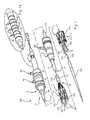
- the delivery catheter 10may also include a prosthesis receiving portion 16, as shown in Fig. 1 .
- the receiving portion 16may be disposed at a proximal portion of the delivery catheter 10 and is configured to receive the stent-graft 112 in a radially compressed configuration. As shown in Fig. 1 , the receiving portion 16 may include a longitudinally extending cannula 106 having a uniform external diameter along its length.
- the sheath 12may be manipulated to selectively deliver and deploy the stent-graft 112 in the body lumen.
- a catheter 104 having a longitudinally uniform external diametermay be included in the delivery system 100.
- the diameter of the catheter 104may be larger than the diameter of the cannula 106.
- a proximal-facing annular abutment surfacemay be disposed at the transition between the cannula 106 and the catheter 104.
- the annular abutment surfacefaces the distal end of the stent-graft 112 and is configured to contact the distal end of the stent-graft 112 during deployment, thereby holding the stent-graft 112 in place at a treatment site within a body lumen or cavity when the sheath 12 is withdrawn in the distal direction.
- the sheath 12may include an elongate tubular body having a wall thickness and a proximal and distal end.
- the sheath 12may be formed as a composite of two or more layers of the same or different materials that are laminated or otherwise mechanically bonded together.
- An inner surface of sheath 12defines a lumen extending along a longitudinal axis thereof.
- the lumenmay have a generally constant diameter along its length.
- the sheath 12extends distally from the delivery section 2 to the user manipulation section 3, which includes a control handle 47.
- the delivery catheter 10is slideably disposed within the lumen.
- the sheath 12may slideably cover and restrain the stent-graft 112 onto the cannula 106 in a radially compressed configuration in which the diameter of the stent-graft 112 is reduced as compared to its unrestrained state.
- the nose cone 102may have a recessed portion disposed at its distal end that is shaped to receive the proximal end of the sheath 12 and form a generally smooth transition therebetween so as to prevent trauma to the body lumen or cavity as the delivery catheter 10 is advanced into the patient for delivery and deployment of the stent-graft 112.
- the distal end of the sheath 12may be configured to remain outside of the body during the procedure, in which case the sheath 12 may be directly manipulated through the control handle 47 by the operator to deploy the stent-graft 112.
- the sheath 12may have a length, as shown in Fig. 1 , that is greater than the length of the stent-graft 112.
- the sheath 12may have a length that is two or more times greater than the length of the stent-graft 112.
- the sheath 12may have a length that is generally equal to or only slightly greater than the length of the stent-graft 112.
- the sheath 12may have a uniform internal diameter. The internal diameter may be substantially equal to the external diameter of the catheter 104 such that the inner surface of the sheath 12 slideably engages the delivery catheter 10.
- the sheath 12may be made of any suitable biocompatible material, for example PTFE, nylon, or polyethylene.
- the sheath 12may optionally include a flat wire coil or braid disposed between or incorporated into the one or more layers of material to provide the sheath 12 with increased pushability and kink-resistance as the sheath 12 is advanced through the body lumen or cavity, as discussed in U.S. Patent No. 5,380,304 and U.S. Published Patent Application No. 2001/0034514 A1 , which are incorporated herein by reference in their entirety.
- the stent-graft 112may include a plurality of self-expanding stents 130 and self-expanding sealing stents 131.
- Stents having self-expanding characteristicsmay be made of stainless steel, materials with elastic memory properties, such as NITINOL, or any other suitable material.
- a suitable self-expanding stentincludes Z-STENTS®, which are available from Cook Incorporated, Bloomington, Indiana, USA.
- the stent-graft 112also may include an anchor, such as an exposed strut or barb, for anchoring the stent-graft 112 in the body lumen.
- an anchorsuch as an exposed strut or barb
- the stents 130 and sealing stents 131may be formed from a single or multiple wires having a zigzag shape and may comprise barbs, or other anchoring mechanisms that extend from the stent.
- the barbs or other anchoring mechanismsengage the surrounding lumen and help prevent migration of the stent-graft 112 after implantation in the body lumen or cavity.
- the stents 130may cover and/or may be at least partially covered by a graft material.
- a graft materialVarious graft materials and configurations may be used. Suitable graft configurations include, but are not limited to films, coatings, sheets of biocompatible fabrics, non-woven materials and porous materials.
- Suitable graft materialsinclude polyesters, such as poly(ethylene terephthalate), polylactide, polyglycolide and copolymers thereof; fluorinated polymers, such as polytetrafluoroethylene (PTFE), expanded PTFE and poly(vinylidene fluoride); polysiloxanes, including polydimethyl siloxane; polyurethanes, including polyetherurethanes, polyurethane ureas, polyetherurethane ureas, polyurethanes containing carbonate linkages and polyurethanes containing siloxane segments; and bioremodelable materials, such as small intestine submucosa ("SIS").
- SISsmall intestine submucosa
- the operatorapplies pressure to the delivery catheter 10 in the proximal direction through the catheter 104.
- the distal end of the stent-graft 112contacts the abutment surface, which exerts a reaction force on the stent-graft 112 that prevents the stent-graft from moving distally with the sheath 12.
- the delivery system 100may also include a distal end deployment control mechanism 39, as shown in Fig. 1 .
- the distal end deployment control mechanism 39releasably retains the distal end of the stent-graft 112.
- the distal end deployment control mechanism 39may include one or more one trigger wires that releasably couple the distal end of the stent-graft 112 to the delivery catheter 10.
- the distal end of the trigger wire for the distal end deployment control mechanism 39may be attached to the release device 44.
- a proximal end control release mechanismmay include one or more diameter reducing members 160 and a locking member 150, all of which may be formed as trigger wires or the like, as described in detail below in connection with Figs. 1b-6 .
- the diameter reducing member(s) 160 and the locking member 150may extend distally to the external manipulation section 3 shown in Fig. 1 , where they are coupled to one or more of the release devices 43, 44.
- the release devices 43, 44may be configured to selectively decouple the proximal and distal ends of the stent-graft 112 from the delivery catheter 10, respectively.
- the distal ends of two diameter reducing members 160may be attached to the release device 44, and the distal end of the locking member 150 may be attached to the release device 43.
- the delivery system 100may include a third, separate release device 45 attached to the distal end of the trigger wire for the distal end deployment control mechanism 39 to allow selective release and retention of the trigger wire of the distal end deployment control mechanism 39 independently of the diameter reducing members 160 and the locking member 150, as shown in Fig. 1 a.
- the third release devicemay 45 be disposed in a slidably movable arrangement on the control handle 47, and may have a similar or identical structure to the release devices 43, 44 pictured in Fig. 1 .
- the release device 45is first unlocked by loosening a set screw or other locking device 46 and then the release device 45 is withdrawn distally, which pulls the trigger wire of the distal end deployment control mechanism 39 in the distal direction and releases the distal end of the stent-graft 112.
- the locking device 46is loosened and the release device 44 is withdrawn distally, which pulls the diameter reducing members 160 in the distal direction and causes the diameter reducing member 160 to disengage from the stent-graft 112, thereby allowing the stent-graft to be released.
- the release device 43can then be unlocked by loosening a separate locking device 46 and the locking member 150 can be released by withdrawing the release device 43 in the distal direction.
- the distal end of one of the diameter reducing members 160may be attached to an additional release device that is separate from the release devices 43, 44, 45. This additional release device may be slidably attached to the control handle 47 and disposed between the release devices 44 and 45.
- the distal end of the other diameter reducing member 160is attached to the release device 44 and the distal end of the locking member 150 is attached to the release device 43. Because each of the diameter reducing members 160 and the locking member 150 are attached to separate, independent release devices, the diameter reducing members 160 and the locking member 150 can be withdrawn from the stent-graft 112 independently of one another.
- the trigger wire of the distal end deployment control mechanism 39may be attached to the release device 44 and the diameter reducing members 160 and the locking member 150 may all be attached to the same release device 43.
- the release device 44is first unlocked by loosening a set screw or other locking device 46 and then the release device 44 is withdrawn distally, which pulls the trigger wire of the distal end deployment control mechanism 39 in the distal direction and releases the distal end of the stent-graft 112.
- the locking device 46is loosened and the release device 43 is withdrawn distally, which pulls the diameter reducing members 160 and the locking member 150 simultaneously in the distal direction and causes the diameter reducing members 160 and the locking member 150 to disengage from the stent-graft 112, thereby allowing the stent-graft to be released.
- Fig. 1billustrates a detailed view of the delivery system 100 with the sheath 12 and distal end deployment control mechanism 39 removed to better illustrate the configuration of the stent-graft 112.
- the nose cone 102is attached to a proximal end of a cannula 106, and the distal end of the cannula 106 is attached to the catheter 104.
- the stent-graft 112is disposed about the cannula 106 in a non-co-axial, tangential relationship relative to a surface of the stent-graft 112 where a central axis of the stent-graft 112 is spaced away from a central axis of the cannula 106.
- the cannula 106is shown in Fig. 1 as having a straight configuration, it may also have a curved configuration, as shown in Fig. 7 , that substantially approximates the curvature of a portion of the body lumen in which the stent-graft 112 is to be deployed, for example, the aortic arch.
- the stent-graft 112is restrained against the curved cannula 106, the stent-graft assumes a curved configuration prior to deployment that also approximates the curvature of the target site of the vessel to increase conformity to the vessel's shape and increase placement accuracy.
- the stent-graft 112includes a tubular graft material 120 attached to a support frame or structure comprising a plurality of stents 130 and sealing stents 131 having an undulating or zigzag configuration.
- the stents 130 and sealing stents 131may comprise a plurality of structural members connected together at their ends by bends.
- the stents 130 and sealing stents 131may be formed from a single wire made of Nitinol, stainless steel, polymers, or other materials having elastic or super elastic properties. Alternatively, the stents 130, 131 may be cut from a cannula or the like. As shown in Fig.
- the sealing stents 131may have a shorter longitudinal length and a higher "frequency" of bends than the stents 130. This higher frequency of bends provides a more even distribution of force along the surface of the graft 120 at the proximal and distal ends.
- the sealing stents 131may be attached to the graft 120 along an inner surface thereof to force the graft 120 directly against the vessel wall to provide better apposition against the vessel wall and prevent fluid from passing between the stent-graft 112 and the vessel wall in the deployed state.
- the stents 130may have a greater overall longitudinal length and a smaller amplitude, and may be made from a thicker material in order to provide a stronger radial force (in a radially outward direction) that is capable of holding the stent-graft 112 in the open configuration upon deployment and maintaining patency of the lumen extending through the stent-graft 112.
- the stents 130 and the sealing stents 131may comprise individual, discreet stents 130a, 130b, 130c, 130d, etc., with each stent/sealing stent having a ring-like shape (e.g. a "stent ring").
- the stents 130a, 130b, 130c, and 130dmay be spaced longitudinally apart from one another in intervals along the length of the graft 120.
- the stent or stent ringsmay be connected together to form a single monolithic structure that extends and wraps around the graft 120 in a helical form along a portion or an entire length thereof.
- the graft 120may be comprised of, or divided into two circumferential sections, herein referred to as sides or halves 121, 122.
- the halves 121, 122may have a half-cylindrical, longitudinally extending shape.
- the halves 121, 122may meet along one edge at a tangent line 123a and along another edge at a tangent line 123b, with the tangent lines 123a, 123b extending in a substantially straight line along the length of the graft 120 from the proximal to the distal end thereof.
- the graft 120may also be divided into three longitudinal portions: a proximal portion 124 including the proximal end of graft 120, an intermediate portion 126, and a distal portion 125 including the distal end of the graft 120. Note that the proximal portion 124, the intermediate portion 126, and the distal portion 125 refer generally to longitudinal regions of the graft 120.
- a locking member connector 110is attached to the proximal and distal ends of the stent-graft 112 at or near the tangent line 123a.
- a plurality of diameter reducing connectors 140which may be formed by sutures, wire loops or the like, are attached to one or more bends of the stents 130, 131 and may also be attached to the graft 120. In one embodiment, the diameter reducing connectors 140 may be attached to bends of the stent ring 130a, which is disposed longitudinally adjacent to the proximal sealing stent 131.
- the diameter reducing connectors 140are also attached to bends of the stents 130b, 130c, which are disposed longitudinally adjacent to, and spaced apart from the stent 130a moving in the distal direction along the length of the graft 120.
- the diameter reducing connectors 140e and 140fare attached to circumferentially adjacent bends aligned at the distal end of the stent 130a.
- the diameter reducing connectors 140c and 140dare attached to circumferentially adjacent bends aligned along the distal end of the stent 130b
- the diameter reducing connectors 140a and 140bare attached to circumferentially adjacent bends aligned along the distal end of the stent 130c.
- diameter reducing ties 140may also be attached to bends of the stent 130d. Additionally, while only two diameter reducing connectors 140 are shown as being attached to each stent 130, more diameter reducing ties 140 may be attached to bends disposed at either the proximal or distal end of each or any of the stents 130.
- the stent-graft 112may be constructed in a mirror image configuration about the tangent line 123a.
- diameter reducing connectors 140may also be attached to the stent rings 130a, 130b, and 130c at bends disposed at the same circumferential position or substantially the same circumferential position on the half 122, as the half 121 shown in, for example, Fig. 3a .
- the diameter reducing connectors 140are circumferentially clocked away from the tangent line 123a in the counter clockwise direction for the half 122 and in the clockwise direction for the half 121.
- the diameter reducing connectors 140are attached to bends of the stents 130a, 130b, and 130c, which are clocked away from the tangent line 123a by between 90 and 180 degrees on the first and second sides 121, 122.
- the diameter reducing connectors 140may be attached to bends of the stents 130 that are clocked away from the tangent line 123a in the counterclockwise direction on side 121 and in the clockwise direction on side 122 such that, when the diameter reducing connectors 140 are drawn toward each other by a diameter reducing member 160, a gather 162 (see e.g., Fig. 5 ) is formed in the graft 120 that is clocked roughly 120 degrees away from the tangent line 123a on one or both of the first and second sides 121, 122.
- a locking member 150may extend from the release device 43, through the catheter 104 and out of an aperture 151 disposed at the proximal end of the catheter 104.
- the locking member 150may be a suture, a wire made from a titanium alloy, such as Nitinol, or other flexible elongate mono or multifilament member of suitable tensile strength.
- the locking member 150may extend from the aperture 151, through the distal locking member connector 110, along either the interior or exterior of the graft 120, through the proximal locking member connector 110, and into the nose cone 102 through an aperture 154.
- the proximal end of the locking member 150may be frictionally attached to the nose cone 102 by an elastomer or other friction locking mechanism housed within the aperture 154. During assembly, the proximal end of the locking member 150 is held stationary while the distal end of the locking member 150 is pulled in the distal direction and fixed to the release device 43 in a tightened configuration.
- the locking member 150pulls the proximal and distal locking member connectors 110 toward the cannula 106 and into a locked configuration in which the locking member 150 is disposed substantially against or adjacent to either the inner or outer surface of the stent-graft 112 (depending on whether the locking member 150 is disposed on the inside or outside of the stent-graft 112) in a region of the graft 120 that substantially corresponds to the tangent line 123a.
- the locking member 150compressively restrains the stent-graft 112 against the cannula 106 in a non-coaxial arrangement.
- the cannula 106may abut the tangent line 123a on the surface of the stent-graft 112.
- a first diameter reducing member 160extends from the release device 44, through the catheter 104 and out of an aperture 152 disposed at the proximal end of the catheter 104.
- the diameter reducing member 160may be formed from a suture, a wire made from a titanium alloy, such as Nitinol, or other flexible elongate mono or multifilament member of suitable tensile strength. From the catheter 104, the diameter reducing member 160 extends along either an internal or external surface of the stent-graft 112.
- the diameter reducing member 160may initially extend from the aperture 152, along the internal surface of the stent-graft 112, and through the diameter reducing connector 140a. The diameter reducing member 160 may then extend through the diameter reducing connector 140b of the stent 130c in a circumferentially downward direction in Fig. 4 . Next the diameter reducing member 160 may extend upward in Fig. 4 to the connector 140c of the stent 130b, and then downward to the connector 140d. This same pattern may be continued for the diameter reducing connectors 140e and 140f of the stent 130a.
- the diameter reducing member 160may then extend proximally along the graft 120 and through the fenestrations 170a-d disposed in the proximal portion 124 of the graft 120. Specifically, the diameter reducing member 160 may extend through the fenestration 170a into the exterior of the stent-graft 112, where it continues to the aperture 170b disposed at or near the tangent line 123 and to the inside of the graft 120. The diameter reducing member 160 may then extend through the fenestration 170c back to the exterior of the stent-graft 112 and through the fenestration 170d, which may be disposed toward the bottom of the stent-graft 112 in Fig. 4 .
- the diameter reducing member 160then extends into the nose cone 102 through an aperture 153 where it is frictionally locked in place by an elastomer or other friction locking mechanism housed within the aperture 153.
- a second diameter reducing member 160is disposed on the opposite side of the graft 120 (side 122) in a similar, mirrored configuration, as described above in connection with Fig. 4 .
- the diameter reducing member 160may 160 initially extend from the aperture 152, along the external surface of the stent-graft 112, and through the diameter reducing connector 140a. The diameter reducing member 160 may then extend through the diameter reducing connector 140b of the stent 130c in a circumferentially downward direction in Fig. 4 . Next the diameter reducing member 160 may extend upward in Fig. 4 to the connector 140c of the stent 130b, and then downward to the connector 140d. This same pattern may be continued for the diameter reducing connectors 140e and 140f of the stent 130a.
- the diameter reducing member 160may then extend proximally along the graft 120 and through the fenestrations 170a-d, which are disposed in the proximal portion 124 of the graft 120. Specifically, the diameter reducing member 160 may extend through the fenestration 170a into the interior of the stent-graft 112 where it continues to the aperture 170b that is disposed at or near the tangent line 123a, and to the outside of the graft 120. The diameter reducing member 160 may then extend through the fenestration 170c, back to the interior of the stent-graft 112 and through the fenestration 170d, which is disposed toward the bottom of the stent-graft 112 in Fig.
- the diameter reducing member 160may then extend into the nose cone 102 through an aperture 153 where it is frictionally locked in place by an elastomer or other friction locking mechanism housed within the aperture 153.
- a second diameter reducing member 160may be disposed on the opposite side of the graft 120 in a similar, mirrored configuration as described above in connection with Fig. 4 .
- the fenestrations 170a-dmay be formed simply by piercing the graft material by a needle or a sharp end of the diameter reducing member 160 themselves.
- the fenestrations 170a-dmay be formed as permanent openings or apertures that are woven or otherwise cut or formed into the graft 120.
- the diameter reducing members 160may be slidably attached to the proximal portion 124 of the stent-graft 112 through connecting members, such as loops of suture or wire disposed at substantially the same positions as the fenestrations 170a-d.
- a diameter reducing member 160amay extend along the internal surface of the stent-graft 112 from the catheter 104, through the diameter reducing connector 140a, which is attached to a bend of the stent 130c on the first side 121 of the graft 120, and to the diameter reducing connector 140d, which is disposed on the second side 122.
- the diameter reducing member 160bmay extend along the internal surface of the stent-graft 112 from the catheter 104, through the diameter reducing connector 140c on the second side 122 of the graft 120, and to the diameter reducing connector 140b on the first side of the graft 120.
- the diameter reducing members 160a and 160bthen extend through the diameter reducing connectors 140 on the stents 130a and 130c in the same pattern and extend proximally along the graft 120 and through the fenestrations 170a-d disposed in the proximal portion 124 of the graft 120 (or through connecting members, such as loops of suture or wire, disposed at substantially the same positions on the graft 120 as the fenestrations 170a-d), as described above in connection with the embodiments shown in Fig. 4 .
- the proximal ends of the diameter reducing members 160are held stationary while the distal end of the diameter reducing members 160 are pulled in the distal direction and fixed to the release device 44 in a tightened configuration.
- the diameter reducing members 160straighten, which causes the diameter reducing connectors 140 attached to each of the respective stents 130 to be drawn circumferentially toward each other. This in turn pulls the bends of the stents 130 to which the diameter reducing connectors 140 are attached toward each other and causes the portion of the graft material disposed between the bends to form gathers 162.
- the stents 130become partially compressed, which partially reduces the overall diameter of the stent-graft 112 in the intermediate portion 126 of the graft 120.
- This compression of the stents 130a, 130b, and 130calso draws the bottom portion of the stent-graft 112 in Fig. 5 toward the cannula 106 in the intermediate portion, thereby creating an overall curved configuration along the length of the stent-graft 112.
- the proximal portion 124 of the graftwhen the first and second diameter reducing members 160 are tightened, in the proximal portion 124 of the graft, the portion of the graft disposed between the fenestrations 170a and 170d on both the first and second sides 121, 122 of the graft 120, are drawn upward toward the cannula 106.
- the diameter reducing members 160reach their fully tightened state on both sides of the stent-graft 121, 122, they force the proximal portion 124 of the stent-graft 112 to assume a compressed, reduced diameter configuration having a three lobed shape with three distinct lobes 180a, 180b, and 180c, as shown in Fig. 5a .
- Fig. 5aIn the embodiment shown in Fig.
- the fenestrations 170a and 170dmay be circumferentially clocked away from the tangent line 123 in the clockwise direction by about 120 degrees on the first side 121 of the graft and about 120 degrees in the counterclockwise direction on the second side 122 of the graft.
- the portion of the graft 120 disposed between the same fenestrations located on second side 122 of the graft 120essentially trisect the graft 120 circumferentially into three substantially equal portions.
- the proximal portion 124forms three lobes having essentially the same size and shape (see Fig. 5a ).
- the fenestrations 170a and 170dmay be circumferentially clocked away from the tangent line 123 by an amount that is less than 120 degrees.
- the distance that the fenestrations 170a and 170d are clocked away from the tangent line 123 on the first side 121may be the same or different than the distance or degree of clocking on the second side 122.
- the portion of the graft 120 disposed between the fenestrations 170a, 170d of the first and second sides 121, 122(which is also disposed opposite the cannula 106 and the upper tangent line 123) is larger than the portion of the graft 120 between the fenestrations 170a, d of the first and second sides and the tangent line 123. Accordingly, when the diameter reducing members 160 are tightened, the lobe 180b is larger than the lobes 180a and 180c, as shown in Fig. 5b .
- Fig. 6illustrates the embodiment of Fig. 5 in which the cannula 106 has a curved configuration that is designed to more closely conform to the curvature of a target site in a vessel, such as the aortic arch.
- the stent-graft 112is still restrained against the cannula 106 along the tangent line 123.
- the overall shape of the stent-graft 112takes on a curved configuration.
- Figs. 8-10illustrate a deployment process for the delivery system 100 having a curved cannula 106, as shown in Fig. 7 .
- the delivery system 100is inserted into a patient's vasculature percutaneously and advanced over a guidewire 1000 to the treatment site in the aortic arch or the like using the Seldinger technique, which is well known in the art.
- the delivery device 100may have radiopaque markers disposed on the retention sheath 12 to indicate circumferential orientation of the delivery device 100 and to allow the operator to ensure that the tangent line 123a, against which the cannula 106 is restrained, is oriented along the side of the vessel having the greatest radius of curvature. Correspondingly, this also aligns the portions of the stent-graft 112 comprising the reduced diameter connectors 140 and fenestrations 170a,d with the side of the vessel having the smallest radius of curvature.
- the stent-graft 112is compressed and restrained in a reduced diameter configuration against the cannula 106 by the retention sheath 12.
- the sheath 12is withdrawn and the distal end deployment control mechanism 39 is manipulated to release the distal end of the stent-graft 112. Once released, the distal end of the stent-graft 112 is allowed to expand outward against the vessel wall.
- the proximal end of the stent-graft 112is still held in the reduced diameter configuration by the reduced diameter members 160 and the locking member 150. In this way, the proximal end of the stent-graft 112 is not subject to a "wind sock" effect where it is pulled open by the blood flow, which flows in the direction indicated by the arrow 1010, and pushed distally through the vessel and away from its desired placement position.
- the cannula 106is curved and the stent-graft 112 is restrained in a non-coaxial manner against a tangent surface thereof, when the retention sheath 112 is withdrawn the intermediate portion 126 and the proximal portion 124 of the stent-graft 112 remain substantially adjacent or abutting the side of the vessel wall having the greatest radius of curvature. At the same time, the reduced diameter side of the stent-graft 112 is spaced away from the side of the vessel having the smallest radius of curvature. As shown in Fig.
- the diameter reducing members 160are withdrawn distally in a proximal to distal progression such that the lobes 180 in the proximal portion 124 are released first. Because the top side of the stent-graft 112 in Fig.8 is already disposed against the portion of the vessel wall having the greatest radius of curvature before the diameter reducing members 160 are withdrawn, the portion of the stent-graft 112 near the tangent line 123a is able anchor to the vessel wall along substantially the entire length of the stent-graft 112 while the proximal end of the stent-graft 112 is released.
- the diameter reducing membersare withdrawn from the intermediate portion 126, thereby releasing the stents 130 and the gathers 162, and allowing the remaining portions of the stent-graft 112 to assume their desired expanded, deployed configuration.
- the stent-graft 112is further able to avoid the pulsatile forces caused by the flow of blood that could push the stent-graft 112 distally away from the desired placement site.
- the force of the blood flowcannot push the proximal portion distally through the curved vessel and cause the bottom side of the stent-graft 112 to deploy in a position where it does not fully conform to the inner curvature of the vasculature.
- a birds beak gap between the stent-graft 112 and the vessel wallis avoided, and the stent-graft 112 is deployed in a configuration that more closely conforms to the curvature of the vessel.
Landscapes
- Health & Medical Sciences (AREA)
- Engineering & Computer Science (AREA)
- Biomedical Technology (AREA)
- Cardiology (AREA)
- Oral & Maxillofacial Surgery (AREA)
- Transplantation (AREA)
- Heart & Thoracic Surgery (AREA)
- Vascular Medicine (AREA)
- Life Sciences & Earth Sciences (AREA)
- Animal Behavior & Ethology (AREA)
- General Health & Medical Sciences (AREA)
- Public Health (AREA)
- Veterinary Medicine (AREA)
- Prostheses (AREA)
- Media Introduction/Drainage Providing Device (AREA)
Abstract
Description
- This invention relates to medical devices and, in particular, to a delivery system for an endoluminal prosthesis and method of deploying the endoluminal prosthesis.
- Endovascular repair of thoracic pathologies is an effective, noninvasive treatment option that has gained tremendous popularity over the last ten years. However, challenging anatomy, such as highly curved or tortuous anatomy often leads to a non-ideal device deployment where the endovascular graft does not fully conform to the inner curvature of the vasculature. When deploying a stent-graft having a substantially cylindrical shape in a curved aorta or other vessel, there is a danger that the proximal end of the stent-graft, which is the end disposed nearer the heart, will not lie flat against the walls of the vessel. In this case, blood can flow underneath the edge of the graft. This problem is particularly common on the inner side of the curve of the aortic arch and is commonly referred to as "birds beaking." Generally the gap formed by "birds beaking" between the inner curve of the aortic wall and the proximal edge of the endovascular graft is in the range of 1-10mm. Such gaps can and have led to device failures including: device migration, stent fatigue/fracture, endoleaks, etc. Accordingly, it has become apparent to the inventors that an improved system for delivering endoluminal prostheses, such as stent-grafts, is desirable.
- Delivery systems for deploying endovascular prostheses, such as stent-grafts, are described which may be readily conformable to a patient's anatomy, for example, curved vessels such as the aortic arch, to allow for more accurate placement thereof. The embodiments may include any of the following aspects in various combinations and may also include any other aspect described below in the written description or in the attached drawings.
- In one aspect, a delivery system for deploying a stent-graft may include: a cannula extending from a distal end to a proximal end; a stent-graft; a locking member extending from the distal end of the cannula to the proximal end of the cannula; and a first diameter reducing member.
- The stent-graft may include a tubular graft extending from a proximal end to a distal end. The graft may include a proximal portion and first and second longitudinally extending sections disposed opposite each other. An intersection of the first and second sections may form a tangent line that extends longitudinally along a length of the graft. The tangent line may be a longitudinal line along the length of stent graft. The locking member may be movable between a locked position, and a released position. When the locking member is in the locked position, the locking member may restrain a surface of the graft against the cannula along the tangent line, and a central axis of the cannula may be spaced away from a central axis of the graft.
- The first diameter reducing member may extend from the distal end of the cannula and along a length of the graft. The first diameter reducing member may be slidably connected to a first portion of the graft that is disposed proximate the tangent line in the proximal portion and may be slidably connected to a second portion of the graft that is spaced circumferentially away from the tangent line in the proximal portion. The first diameter reducing member may have a restrained position and a released position. When the first diameter reducing member is in the restrained position, the second portion of the graft is drawn toward the first portion of the graft such that the proximal portion of the stent-graft has a reduced diameter configuration with at least two lobes that extend away from the tangent line and the cannula. When the first diameter reducing member is in the released position, the second portion is disposed away from the first portion of the graft, the proximal portion of the graft thereby having a substantially tubular configuration. The tangent line or longitudinal line along the stent graft may extend from the proximal end to the distal end of the stent graft. The stent graft may be held against the cannula along the tangent line or longitudinal line by the locking member. The stent graft may comprise at least one connector portion on the longitudinal line which may be engaged by the locking member to attach the stent graft to the cannula. Preferably the stent graft comprises two connector portions on the longitudinal line. A first connector portion may be located on the longitudinal line at the proximal end of the stent graft. A second connector portion may be located on the longitudinal line at the distal end of the stent graft. The longitudinal line may extend between the connector portions.
- In another aspect, the delivery system may also include a second diameter reducing member extending from the distal end of the cannula and along a length of the graft. The second diameter reducing member may be slidably connected to a third portion of the graft that is disposed proximate the tangent line in the proximal portion and slidably connected to a fourth portion of the graft that is disposed in a position circumferentially spaced away from the tangent line in the proximal portion. The second diameter reducing member may have a restrained position and a released position. When the first and second diameter reducing members are in the restrained position, the fourth portion of the graft may be drawn toward the third portion of the graft such that the proximal portion of the stent-graft has a reduced diameter configuration with three lobes that extend away from the tangent line and the cannula. When the first and fourth diameter reducing members are in the released position, the second portion may be disposed away from the third portion of the graft, the proximal portion of the graft thereby having the substantially tubular configuration.
- The proximal portion may comprise at least one first section lower fenestration spaced circumferentially away from the tangent line on the first section of the graft, and at least one upper fenestration disposed proximate to the tangent line. The first diameter reducing member may extend along the first section of the graft. The first diameter reducing member may extend through the lower fenestration, through the upper fenestration, and to the proximal end of the cannula.
- The delivery system may comprise at least one second section lower fenestration spaced circumferentially away from the tangent line on the second section of the graft. The delivery system may comprise a second diameter reducing member slidably connected to the stent graft. The second diameter reducing member may extend along the second section of the graft in the proximal portion, through the second section lower fenestration, through the upper fenestration, and to the proximal end of the cannula. The second diameter reducing member may be movable between a restrained position and a released position. When the first and second diameter reducing members are in the restrained position, portions of the graft disposed proximate to the first section lower fenestrations and the second section lower fenestration may be drawn toward a portion of the graft disposed proximate to the at least one upper fenestration, the proximal portion of the stent-graft thereby having a reduced diameter configuration with at least three lobes.
- The at least one first section lower fenestration may comprise a first and second fenestration. The upper fenestration may comprise third and fourth fenestrations. The first diameter reducing member may extend: 1) along the graft in the proximal portion, 2) through the first fenestration, 3) through the third fenestration, 4) through the fourth fenestration, 5) through the second fenestration, and 6) to the proximal end of the cannula.
- The at least one second section lower fenestration may comprise a fifth and sixth fenestration. The upper fenestration may comprise seventh and eighth fenestrations. The second diameter reducing member may extend: 1) along the second section of the graft in the proximal portion, 2) through the fifth fenestration, 3) through the seventh fenestration, 4) through the eighth fenestration, 5) through the sixth fenestration, and 6) to the proximal end of the cannula.
- A portion of the graft disposed between the first and second fenestrations may be circumferentially spaced away from the tangent line by about 120 degrees on the first section of the graft. A portion of the graft disposed between the third and fourth fenestrations may circumferentially spaced away from the tangent line by about 120 degrees on the second section of the graft. When the first and second diameter reducing members are in the restrained position, the three lobes may be substantially the same size.
- A portion of the graft disposed between the first and second fenestrations may be circumferentially spaced away from the tangent line by a first distance on the first section. A portion of the graft disposed between the fifth and sixth fenestrations may be circumferentially spaced away from the tangent line by a second distance on the second section of the graft. The first and second distances may be the same. The first and second distances may be less than 1/3 of the circumference of the graft. In this case, when the first and second diameter reducing members are in the restrained position, the lobe including the portion of the graft disposed opposite the tangent line may be larger than the remaining two lobes.
- In another aspect, the stent-graft further may include a support structure attached to the graft. The support structure may include at least a first stent ring, where the first stent ring comprises a plurality of structural members connected by bends in an undulating pattern. A first diameter reducing connector may be attached to a first bend of the first stent ring, and a second diameter reducing connector may be attached to a second bend of the first stent ring. The first ring may be attached to an intermediate portion of the graft, and the first and second bends may be disposed on the first section of the graft and spaced circumferentially away from the tangent line.
- In another aspect, the first diameter reducing member may extend from the first diameter reducing connector to the second diameter reducing connector in the intermediate portion of the graft. When the first diameter reducing member is in the restrained position, the first bend may be drawn circumferentially toward the second bend, thereby forming a first gather in the first section of the graft that decreases the diameter of the stent-graft in the intermediate portion.
- The delivery system may comprise a second stent ring attached to the intermediate portion of the graft. The second stent ring may comprise a plurality of structural members connected by bends in an undulating pattern. A third diameter reducing connector may be attached to a first bend of the second stent ring. A fourth diameter reducing connector may be attached to a second bend of the second stent ring. The second ring may be attached to the intermediate portion of the graft. The first and second bends of the second ring may be disposed on the first section of the graft and circumferentially spaced away from the tangent line. In the intermediate portion, the first diameter reducing member may further extend from the second diameter reducing connector to the third diameter reducing connector, and from the third diameter reducing connector to the fourth diameter reducing connector. When the first diameter reducing member is in the restrained position, the first bend of the second stent ring may be drawn circumferentially toward the second bend of the second stent ring, thereby forming a second gather in the graft that further decreases the diameter of the stent-graft in the intermediate portion.
- The first and second bends of the first stent ring and the first and second bends of the second stent ring may be circumferentially spaced away from the tangent line between 90 and 120 degrees on the first section of the graft.
- The stent-graft may comprise a fifth diameter reducing connector attached to a third bend of the first stent ring and a sixth diameter reducing connector attached to a fourth bend of the first stent ring. The third and fourth bends of the first stent ring may be disposed on the second section of the graft and circumferentially spaced away from the tangent line.
- In the intermediate portion, the second diameter reducing member extends from the fifth diameter reducing connector to the sixth diameter reducing connector. When the second diameter reducing member is in the restrained position, the third bend of the first stent ring may be drawn circumferentially toward the fourth bend of the first stent ring, thereby forming a third gather in the graft that further decreases the diameter of the stent-graft in the intermediate portion.
- The delivery system may comprise a seventh diameter reducing connector attached to a third bend of the second stent ring and an eighth diameter reducing connector attached to a fourth bend of the second stent ring. The third and fourth bends of the second stent ring may be disposed on the second section of the graft and circumferentially spaced away from the tangent line.
- In the intermediate portion, the second diameter reducing member may further extends from the sixth diameter reducing connector to the seventh diameter reducing connector, and from the seventh diameter reducing connector to the eighth diameter reducing connector. When the second diameter reducing member is in the restrained position, the third bend of the second stent ring may be drawn circumferentially toward the fourth bend of the second stent ring, thereby forming a fourth gather in the graft that further decreases the diameter of the stent-graft in the intermediate portion.
- The third and fourth bends of the first stent ring and the third and fourth bends of the second stent ring may be circumferentially spaced away from the tangent line between 90 and 120 degrees on the second section of the graft.
- A method of repairing a damaged or diseased vessel may include: providing a delivery system as described above; restraining a surface of the graft against the cannula along the tangent line and displacing a central axis of the cannula away from a central axis of the graft by moving the locking member to the locked configuration; forming a reduced diameter configuration in the proximal portion of the stent-graft having at least two lobes by moving the first diameter reducing member to the restrained position and draw the second portion of the graft toward the first portion of the graft; advancing the delivery system into a curved lumen; and moving the diameter reducing members to the released position, whereby the proximal portion of the stent graft is released from the reduced diameter configuration and the proximal portion of the stent-graft assumes a substantially tubular configuration. The delivery system may comprise, for example, a cannula extending from a distal end to a proximal end; a tubular graft extending from a proximal end to a distal end, the graft comprising a proximal portion, the graft comprising first and second longitudinally extending sections disposed opposite each other, an intersection of the first and second sections forming a tangent line that extends longitudinally along a length of the graft; a locking member extending from the distal end of the cannula, the locking member being movable between a locked position, and a released position; and a diameter reducing member extending from a distal end of the cannula and along a length of the graft, the diameter reducing member being slidably connected to a first portion of the graft that is disposed proximate the tangent line in the proximal portion and slidably connected to a second portion of the graft that is disposed in a position circumferentially spaced away from the tangent line in the proximal portion, the diameter reducing member having a restrained position and a released position.
- Also described is a delivery system for deploying a stent-graft in a curved lumen, the deployment system comprising: a curved cannula extending in an arced configuration from a distal end to a proximal end; a stent-graft, the stent-graft comprising: a tubular graft having a proximal portion and an intermediate portion, the graft comprising first and second longitudinally extending sides disposed opposite each other, an intersection of the first and second sides forming a tangent line that extends longitudinally along a length of the graft, wherein the proximal portion comprises: 1) first and second fenestrations circumferentially spaced away from the tangent line on the first side of the graft; 2) third and fourth fenestrations circumferentially spaced away from the tangent line on the second side of the graft; and 3) fifth through eighth fenestrations disposed proximate the tangent line; a locking member extending from the distal end of the cannula the locking member being movable between a locked position, and a released position, wherein, when the locking member is in the locked position, the locking member restrains a surface of the graft against the cannula along the tangent line, and a central axis of the cannula is spaced away from a central axis of the graft; and a first diameter reducing member extending from the distal end of the cannula and along the graft, the first diameter reducing member extending in the proximal portion of the graft: 1) along the graft in the proximal portion, 2) through the first fenestration, 3) through the fifth fenestration, 4) through the sixth fenestration, 5) through the second fenestration, and 6) to the proximal end of the cannula; a second diameter reducing member extending from the distal end of the cannula and along the graft, the second diameter reducing member extending in the proximal portion of the graft: 1) along the second side of the graft in the proximal portion, 2) through the third fenestration, 3) through the seventh fenestration, 4) through the eighth fenestration, 5) through the fourth fenestration, and 6) to the proximal end of the cannula, wherein when the first and second diameter reducing members are in a restrained position, a portion of the graft disposed between the first and second fenestrations is drawn toward a portion of the graft disposed between the fifth and sixth fenestrations, and a portion of the graft disposed between the third and fourth fenestrations is drawn toward a portion of the graft disposed between the seventh and eighth fenestrations, the proximal portion of the stent-graft thereby having a reduced diameter configuration with three lobes.
- The delivery system may comprise a support structure attached to the graft, the support structure comprising at least a first stent ring, the first stent ring comprising a plurality of structural members connected by bends in an undulating pattern; a first diameter reducing connector attached to a first bend of the first stent ring; a second diameter reducing connector attached to a second bend of the first stent ring; a third diameter reducing connector attached to a third bend of the first stent ring; a fourth diameter reducing connector attached to a fourth bend of the first stent ring, wherein the first stent ring is attached to the intermediate portion of the graft, wherein the first and second bends are disposed on the first section of the graft and circumferentially spaced away from the tangent line, and wherein the third and fourth bends are disposed on the second section of the graft and circumferentially spaced away from the tangent line; wherein, in the intermediate portion, the first diameter reducing member extends along the second side of the graft to one of the third or fourth diameter reducing connectors and further to one of the first or second diameter reducing connectors, and the second diameter reducing member extends along the first side of the graft from the other of the first or second diameter reducing connectors to the other of the first or second diameter reducing connectors, and wherein, when the first and second diameter reducing members are in the restrained position, the first and second bends are drawn toward the third and fourth bends, thereby forming at least one gather in the graft that decrease the diameter of the stent-graft in the intermediate portion.
- The portion of the graft disposed between the first and second fenestrations may be circumferentially spaced away from the tangent line by about 120 degrees on the first section of the graft. The portion of the graft disposed between the third and fourth fenestrations may be circumferentially spaced away from the tangent line by about 120 degrees on the second section of the graft. When the first and second diameter reducing members are in the restrained position, the three lobes may be substantially the same size.
- The foregoing paragraphs have been provided by way of general introduction, and are not intended to limit the scope of the following claims.
- Embodiments of the present invention are described below, by way of example only, with reference to the accompanying drawings, in which:
Fig. 1 is a perspective view of a delivery system for an endoluminal prosthesis;Fig. 1 a is a close-up view of an alternative embodiment of a control handle arrangement of the delivery system ofFig.1 ;Fig. 1b is a side perspective view of the delivery system ofFig. 1 ;Fig. 2 is a front cross sectional view of a graft taken along the line X-X ofFig. 1b ;Fig. 2a is a perspective view of the graft ofFig. 2 ;Fig. 3 is a side perspective view of the delivery system ofFig. 1 including a locking member;Fig. 3a is a cross-sectional view of the stent-graft ofFig. 3 taken long the line Y-Y;Fig. 4 is a side perspective view of the delivery system ofFig. 1 including a diameter reducing member;Fig. 4a is a perspective view of a portion of a stent-graft illustrating an alternative embodiment to the embodiment shown inFig. 4 ;Fig. 4b is an end view of the embodiment ofFig. 4a ;Fig. 5 is a side perspective view of the delivery system ofFig. 1 illustrating the diameter reducing member in a tightened configuration;Fig. 5a is a front cross-sectional view taken along the line X-X of the graft ofFig. 5 in a three lobed reduced diameter configuration;Fig. 5b is an alternative three lobed configuration of the graft ofFig. 5a ;Fig. 6 is a side view of the endoluminal prosthesis ofFig. 5 mounted on a delivery system having a curved cannula;Fig. 7 is a side view of the delivery system ofFig. 6 illustrating the curved cannula;Fig. 8 illustrates the delivery system ofFig. 6 in an initial deployment configuration;Fig. 9 illustrates the delivery system ofFig. 6 in an intermediate deployment configuration; andFig. 10 illustrates the delivery system ofFig. 6 in a fully deployed configuration.- The components of the drawings are not necessarily to scale, emphasis instead being placed upon illustrating the principles of the teachings herein. The embodiments described here may be more fully understood by reading the following description in conjunction with the drawings.
- Throughout this specification, like reference numbers refer to like elements.
- The terms "distal" and "distally" refer to a position, direction, or orientation that is generally away from the heart. The terms "proximal" and "proximally" refer to a position, direction, or orientation that is generally toward, or closer to the heart.
- The terms "endoluminal device" or "endoluminal prosthesis" refer to or describe objects that can be placed inside a vessel, a lumen, or a body passageway in a human or animal body. A lumen, vessel, or a body passageway can be a naturally occurring lumen or a lumen created by surgical intervention. As used in this specification, the terms "lumen" or "body passageway" are intended to have a broad meaning and encompasses any duct (e.g., natural or iatrogenic) within the human body and can include blood vessels, respiratory ducts, gastrointestinal ducts, and the like. Thus, "Endoluminal device" or "endoluminal prosthesis" describes devices that can be placed inside one of these lumens.
- The term "fenestration" refers to an opening in a generally fluid impermeable structure through which fluid can pass.
- The term "stent" means any device or structure that adds rigidity, expansion force or support to a prosthesis or body lumen. A stent is used to obtain and/or maintain a patency of the body passageway while maintaining the integrity of the passageway. In addition, a stent may be used to form a fluid seal against the body lumen. The stent may be coated with a polymeric material, for example, by immersion in liquid polymer or any other method known to one of skill in the art. The stent may be located on the exterior of a prosthesis, an interior of the prosthesis, or both. A stent may be self-expanding, balloon-expandable or may have characteristics of both.
- The term "graft" or "graft material" may comprise a biocompatible synthetic or biological material. Examples of suitable synthetic materials include fabrics, woven and non-woven materials, and porous and non-porous sheet materials. One exemplary synthetic graft material includes a woven polyester having a twill weave and a porosity of about 350 ml/min/cm2, and is available from VASCUTEK® Ltd., Renfrewshire, Scotland, UK. Other synthetic graft materials include biocompatible materials such as polyester, polytetrafluoroethylene (PTFE), polyurethane, and the like. Examples of suitable biological materials include, for example, pericardial tissue and extracellular matrix materials such as SIS.
- Examples of suitable graft materials are described in
U.S. Patent Nos. 4,502,159 ,4,675,361 ,4,861,830 ,4,902,508 ,5,017,664 ,5,733,337 ,6,206,931 ,6,358,284 ,6,379,710 ,6,666,892 ,6,752,826 , and6,939,377 , inU.S. Patent Application Publication Nos. 2002/0187288 A1 and2003/0149471 A1 , and inPCT Published Patent Application No. WO 98/22158 - The term "vessel" refers to a tube, cavity, duct, or canal in which fluid may be contained and conveyed or circulated. A body vessel (as opposed to a prosthetic vessel) is a vessel that exists naturally, or is formed naturally in the body. Examples of body vessels include, but are not limited to, blood vessels such as the aorta and the femoral artery, the esophagus, the trachea, the ureter, the bile duct, and the like. Examples of prosthetic vessels include, but are not limited to, stents, grafts, stent-grafts, venous or aortal valves, vena cava filters, and the like.
- The term "lumen" describes a space within a vessel in which fluid may be contained, conveyed, and/or circulated. The term "endoluminal" means within a lumen, and can refer to objects that are found or that can be placed within a lumen, or methods or processes that occur within a lumen. An "endoluminal prosthesis" is a prosthesis that is found or that can be placed within a lumen. Examples of endoluminal prostheses include, but are not limited to, stents, grafts, stent-grafts, venous or aortal valves, vena cava filters, and the like. An endoluminal prosthesis may be generally tubular and comprise one or more lumens. Examples of tubular prostheses include, but are not limited to, straight, curved, branched, and bifurcated prostheses.
- The term "clock" or "clocked" refers to an orientation that is circumferentially spaced away from a fixed reference point in a manner similar to the numbers on an analog clock, which are circumferentially spaced away from each other. For example, as shown in
Fig. 2 , thepoint 123d is "clocked" circumferentially away from thetangent line 123a in the clockwise direction. Similarly, thepoint 123c is clocked circumferentially away from thetangent line 123a in the counterclockwise direction. In other words, a location which is clocked away from a particular point or line may be spaced from that line by a given angle about a circumerence. Referring now to the figures,Fig. 1 illustrates an embodiment of adelivery system 100 for delivering and deploying a medical device, such as the stent-graft 112 shown inFigs. 1b-6 . Thedelivery system 100 may include adelivery catheter 10 and asheath 12. In operation, thedelivery catheter 10 and thesheath 12 are configured to selectively retain and release the stent-graft 112. Thedelivery catheter 10 has a proximal end and a distal end. - A dilator head, also referred to as a
nose cone 102, is disposed at the proximal end of thedelivery catheter 10. Thenose cone 102 is tapered in the distal direction to provide for a smooth, atraumatic transition from a guidewire over which thedelivery system 100 is advanced into a body lumen or cavity. Aguidewire lumen 15 extends longitudinally through thedelivery catheter 10 between the proximal and distal ends. Thedelivery catheter 10 is configured to receive a guidewire through theguidewire lumen 15. Thedelivery catheter 10 may also include aprosthesis receiving portion 16, as shown inFig. 1 . The receivingportion 16 may be disposed at a proximal portion of thedelivery catheter 10 and is configured to receive the stent-graft 112 in a radially compressed configuration. As shown inFig. 1 , the receivingportion 16 may include alongitudinally extending cannula 106 having a uniform external diameter along its length. - The
sheath 12 may be manipulated to selectively deliver and deploy the stent-graft 112 in the body lumen. As shown inFig. 1 , acatheter 104 having a longitudinally uniform external diameter may be included in thedelivery system 100. The diameter of thecatheter 104 may be larger than the diameter of thecannula 106. A proximal-facing annular abutment surface may be disposed at the transition between thecannula 106 and thecatheter 104. The annular abutment surface faces the distal end of the stent-graft 112 and is configured to contact the distal end of the stent-graft 112 during deployment, thereby holding the stent-graft 112 in place at a treatment site within a body lumen or cavity when thesheath 12 is withdrawn in the distal direction. - The
sheath 12 may include an elongate tubular body having a wall thickness and a proximal and distal end. Thesheath 12 may be formed as a composite of two or more layers of the same or different materials that are laminated or otherwise mechanically bonded together. An inner surface ofsheath 12 defines a lumen extending along a longitudinal axis thereof. The lumen may have a generally constant diameter along its length. Thesheath 12 extends distally from thedelivery section 2 to theuser manipulation section 3, which includes acontrol handle 47. Thedelivery catheter 10 is slideably disposed within the lumen. Thesheath 12 may slideably cover and restrain the stent-graft 112 onto thecannula 106 in a radially compressed configuration in which the diameter of the stent-graft 112 is reduced as compared to its unrestrained state. Thenose cone 102 may have a recessed portion disposed at its distal end that is shaped to receive the proximal end of thesheath 12 and form a generally smooth transition therebetween so as to prevent trauma to the body lumen or cavity as thedelivery catheter 10 is advanced into the patient for delivery and deployment of the stent-graft 112. The distal end of thesheath 12 may be configured to remain outside of the body during the procedure, in which case thesheath 12 may be directly manipulated through the control handle 47 by the operator to deploy the stent-graft 112. - The
sheath 12 may have a length, as shown inFig. 1 , that is greater than the length of the stent-graft 112. For example, thesheath 12 may have a length that is two or more times greater than the length of the stent-graft 112. Alternatively, thesheath 12 may have a length that is generally equal to or only slightly greater than the length of the stent-graft 112. Thesheath 12 may have a uniform internal diameter. The internal diameter may be substantially equal to the external diameter of thecatheter 104 such that the inner surface of thesheath 12 slideably engages thedelivery catheter 10. - The
sheath 12 may be made of any suitable biocompatible material, for example PTFE, nylon, or polyethylene. Thesheath 12 may optionally include a flat wire coil or braid disposed between or incorporated into the one or more layers of material to provide thesheath 12 with increased pushability and kink-resistance as thesheath 12 is advanced through the body lumen or cavity, as discussed inU.S. Patent No. 5,380,304 andU.S. Published Patent Application No. 2001/0034514 A1 , which are incorporated herein by reference in their entirety. - As shown in
Figs. 1 and1b , the stent-graft 112 may include a plurality of self-expandingstents 130 and self-expandingsealing stents 131. Stents having self-expanding characteristics may be made of stainless steel, materials with elastic memory properties, such as NITINOL, or any other suitable material. A suitable self-expanding stent includes Z-STENTS®, which are available from Cook Incorporated, Bloomington, Indiana, USA. When thesheath 12 is removed, thecompressed stents 130 and sealingstents 131 cause the stent-graft 112 to expand. The stent-graft 112 also may include an anchor, such as an exposed strut or barb, for anchoring the stent-graft 112 in the body lumen. As shown inFigs.1 and1b , thestents 130 and sealingstents 131 may be formed from a single or multiple wires having a zigzag shape and may comprise barbs, or other anchoring mechanisms that extend from the stent. When thestents 130 and sealingstents 131 are released, the barbs or other anchoring mechanisms engage the surrounding lumen and help prevent migration of the stent-graft 112 after implantation in the body lumen or cavity. - The
stents 130 may cover and/or may be at least partially covered by a graft material. Various graft materials and configurations may be used. Suitable graft configurations include, but are not limited to films, coatings, sheets of biocompatible fabrics, non-woven materials and porous materials. Examples of suitable graft materials include polyesters, such as poly(ethylene terephthalate), polylactide, polyglycolide and copolymers thereof; fluorinated polymers, such as polytetrafluoroethylene (PTFE), expanded PTFE and poly(vinylidene fluoride); polysiloxanes, including polydimethyl siloxane; polyurethanes, including polyetherurethanes, polyurethane ureas, polyetherurethane ureas, polyurethanes containing carbonate linkages and polyurethanes containing siloxane segments; and bioremodelable materials, such as small intestine submucosa ("SIS"). - In operation, when the
sheath 12 is withdrawn distally, the operator applies pressure to thedelivery catheter 10 in the proximal direction through thecatheter 104. As thesheath 12 is withdrawn, the distal end of the stent-graft 112 contacts the abutment surface, which exerts a reaction force on the stent-graft 112 that prevents the stent-graft from moving distally with thesheath 12. - The
delivery system 100 may also include a distal enddeployment control mechanism 39, as shown inFig. 1 . The distal enddeployment control mechanism 39 releasably retains the distal end of the stent-graft 112. The distal enddeployment control mechanism 39 may include one or more one trigger wires that releasably couple the distal end of the stent-graft 112 to thedelivery catheter 10. The distal end of the trigger wire for the distal enddeployment control mechanism 39 may be attached to therelease device 44. A proximal end control release mechanism may include one or morediameter reducing members 160 and a lockingmember 150, all of which may be formed as trigger wires or the like, as described in detail below in connection withFigs. 1b-6 . The diameter reducing member(s) 160 and the lockingmember 150 may extend distally to theexternal manipulation section 3 shown inFig. 1 , where they are coupled to one or more of therelease devices release devices graft 112 from thedelivery catheter 10, respectively. For example, in one embodiment, the distal ends of twodiameter reducing members 160 may be attached to therelease device 44, and the distal end of the lockingmember 150 may be attached to therelease device 43. In this embodiment, thedelivery system 100 may include a third,separate release device 45 attached to the distal end of the trigger wire for the distal enddeployment control mechanism 39 to allow selective release and retention of the trigger wire of the distal enddeployment control mechanism 39 independently of thediameter reducing members 160 and the lockingmember 150, as shown inFig. 1 a. The third release device may 45 be disposed in a slidably movable arrangement on the control handle 47, and may have a similar or identical structure to therelease devices Fig. 1 . - In operation, the
release device 45 is first unlocked by loosening a set screw orother locking device 46 and then therelease device 45 is withdrawn distally, which pulls the trigger wire of the distal enddeployment control mechanism 39 in the distal direction and releases the distal end of the stent-graft 112. Next, the lockingdevice 46 is loosened and therelease device 44 is withdrawn distally, which pulls thediameter reducing members 160 in the distal direction and causes thediameter reducing member 160 to disengage from the stent-graft 112, thereby allowing the stent-graft to be released. Following withdrawal of thediameter reducing members 160, therelease device 43 can then be unlocked by loosening aseparate locking device 46 and the lockingmember 150 can be released by withdrawing therelease device 43 in the distal direction. In one alternative embodiment, the distal end of one of thediameter reducing members 160 may be attached to an additional release device that is separate from therelease devices release devices diameter reducing member 160 is attached to therelease device 44 and the distal end of the lockingmember 150 is attached to therelease device 43. Because each of thediameter reducing members 160 and the lockingmember 150 are attached to separate, independent release devices, thediameter reducing members 160 and the lockingmember 150 can be withdrawn from the stent-graft 112 independently of one another. - Returning to the embodiment of
Fig. 1 , the trigger wire of the distal enddeployment control mechanism 39 may be attached to therelease device 44 and thediameter reducing members 160 and the lockingmember 150 may all be attached to thesame release device 43. In this embodiment, therelease device 44 is first unlocked by loosening a set screw orother locking device 46 and then therelease device 44 is withdrawn distally, which pulls the trigger wire of the distal enddeployment control mechanism 39 in the distal direction and releases the distal end of the stent-graft 112. Next, the lockingdevice 46 is loosened and therelease device 43 is withdrawn distally, which pulls thediameter reducing members 160 and the lockingmember 150 simultaneously in the distal direction and causes thediameter reducing members 160 and the lockingmember 150 to disengage from the stent-graft 112, thereby allowing the stent-graft to be released. Fig. 1b illustrates a detailed view of thedelivery system 100 with thesheath 12 and distal enddeployment control mechanism 39 removed to better illustrate the configuration of the stent-graft 112. As shown inFig. 1b , thenose cone 102 is attached to a proximal end of acannula 106, and the distal end of thecannula 106 is attached to thecatheter 104. The stent-graft 112 is disposed about thecannula 106 in a non-co-axial, tangential relationship relative to a surface of the stent-graft 112 where a central axis of the stent-graft 112 is spaced away from a central axis of thecannula 106. While thecannula 106 is shown inFig. 1 as having a straight configuration, it may also have a curved configuration, as shown inFig. 7 , that substantially approximates the curvature of a portion of the body lumen in which the stent-graft 112 is to be deployed, for example, the aortic arch. As will be described in detail below and shown inFig. 6 , because the stent-graft 112 is restrained against thecurved cannula 106, the stent-graft assumes a curved configuration prior to deployment that also approximates the curvature of the target site of the vessel to increase conformity to the vessel's shape and increase placement accuracy.- Returning to
Fig. 1b , the stent-graft 112 includes atubular graft material 120 attached to a support frame or structure comprising a plurality ofstents 130 and sealingstents 131 having an undulating or zigzag configuration. Thestents 130 and sealingstents 131 may comprise a plurality of structural members connected together at their ends by bends. Thestents 130 and sealingstents 131 may be formed from a single wire made of Nitinol, stainless steel, polymers, or other materials having elastic or super elastic properties. Alternatively, thestents Fig. 1b , the sealingstents 131 may have a shorter longitudinal length and a higher "frequency" of bends than thestents 130. This higher frequency of bends provides a more even distribution of force along the surface of thegraft 120 at the proximal and distal ends. The sealingstents 131 may be attached to thegraft 120 along an inner surface thereof to force thegraft 120 directly against the vessel wall to provide better apposition against the vessel wall and prevent fluid from passing between the stent-graft 112 and the vessel wall in the deployed state. In contrast, thestents 130 may have a greater overall longitudinal length and a smaller amplitude, and may be made from a thicker material in order to provide a stronger radial force (in a radially outward direction) that is capable of holding the stent-graft 112 in the open configuration upon deployment and maintaining patency of the lumen extending through the stent-graft 112. As shown inFigs. 1b-6 , thestents 130 and the sealingstents 131 may comprise individual,discreet stents stents graft 120. In another embodiment, the stent or stent rings may be connected together to form a single monolithic structure that extends and wraps around thegraft 120 in a helical form along a portion or an entire length thereof. - Turning to
Fig. 2a , thegraft 120 may be comprised of, or divided into two circumferential sections, herein referred to as sides orhalves Fig. 2a , thehalves halves tangent line 123a and along another edge at atangent line 123b, with thetangent lines graft 120 from the proximal to the distal end thereof. Thegraft 120 may also be divided into three longitudinal portions: aproximal portion 124 including the proximal end ofgraft 120, anintermediate portion 126, and adistal portion 125 including the distal end of thegraft 120. Note that theproximal portion 124, theintermediate portion 126, and thedistal portion 125 refer generally to longitudinal regions of thegraft 120. - Returning to
Fig. 1b , a lockingmember connector 110 is attached to the proximal and distal ends of the stent-graft 112 at or near thetangent line 123a. A plurality ofdiameter reducing connectors 140, which may be formed by sutures, wire loops or the like, are attached to one or more bends of thestents graft 120. In one embodiment, thediameter reducing connectors 140 may be attached to bends of thestent ring 130a, which is disposed longitudinally adjacent to the proximal sealingstent 131. In this embodiment, thediameter reducing connectors 140 are also attached to bends of thestents stent 130a moving in the distal direction along the length of thegraft 120. Specifically, thediameter reducing connectors stent 130a. Similarly, thediameter reducing connectors stent 130b, and thediameter reducing connectors stent 130c. While no diameter reducing connectors are shown as being attached to the distalmost stent 130d, it should be understood thatdiameter reducing ties 140 may also be attached to bends of thestent 130d. Additionally, while only twodiameter reducing connectors 140 are shown as being attached to eachstent 130, morediameter reducing ties 140 may be attached to bends disposed at either the proximal or distal end of each or any of thestents 130. - Note that while only one side of the stent-
graft 112 corresponding to thehalf 121 is shown inFigs. 1b-6 , the stent-graft 112 may be constructed in a mirror image configuration about thetangent line 123a. Thus,diameter reducing connectors 140 may also be attached to the stent rings 130a, 130b, and 130c at bends disposed at the same circumferential position or substantially the same circumferential position on thehalf 122, as thehalf 121 shown in, for example,Fig. 3a . As shown inFig. 3a , thediameter reducing connectors 140 are circumferentially clocked away from thetangent line 123a in the counter clockwise direction for thehalf 122 and in the clockwise direction for thehalf 121. Preferably, thediameter reducing connectors 140 are attached to bends of thestents tangent line 123a by between 90 and 180 degrees on the first andsecond sides Figs. 5-5b and described in detail below, in one embodiment, thediameter reducing connectors 140 may be attached to bends of thestents 130 that are clocked away from thetangent line 123a in the counterclockwise direction onside 121 and in the clockwise direction onside 122 such that, when thediameter reducing connectors 140 are drawn toward each other by adiameter reducing member 160, a gather 162 (see e.g.,Fig. 5 ) is formed in thegraft 120 that is clocked roughly 120 degrees away from thetangent line 123a on one or both of the first andsecond sides - Turning to
Fig. 3 , a lockingmember 150 may extend from therelease device 43, through thecatheter 104 and out of anaperture 151 disposed at the proximal end of thecatheter 104. The lockingmember 150 may be a suture, a wire made from a titanium alloy, such as Nitinol, or other flexible elongate mono or multifilament member of suitable tensile strength. As shown inFig. 3 , the lockingmember 150 may extend from theaperture 151, through the distallocking member connector 110, along either the interior or exterior of thegraft 120, through the proximallocking member connector 110, and into thenose cone 102 through anaperture 154. The proximal end of the lockingmember 150 may be frictionally attached to thenose cone 102 by an elastomer or other friction locking mechanism housed within theaperture 154. During assembly, the proximal end of the lockingmember 150 is held stationary while the distal end of the lockingmember 150 is pulled in the distal direction and fixed to therelease device 43 in a tightened configuration. As the lockingmember 150 tightens, the lockingmember 150 pulls the proximal and distallocking member connectors 110 toward thecannula 106 and into a locked configuration in which the lockingmember 150 is disposed substantially against or adjacent to either the inner or outer surface of the stent-graft 112 (depending on whether the lockingmember 150 is disposed on the inside or outside of the stent-graft 112) in a region of thegraft 120 that substantially corresponds to thetangent line 123a. In this locked configuration, the lockingmember 150 compressively restrains the stent-graft 112 against thecannula 106 in a non-coaxial arrangement. For example, thecannula 106 may abut thetangent line 123a on the surface of the stent-graft 112. - As shown in
Fig. 4 , a firstdiameter reducing member 160 extends from therelease device 44, through thecatheter 104 and out of anaperture 152 disposed at the proximal end of thecatheter 104. Thediameter reducing member 160 may be formed from a suture, a wire made from a titanium alloy, such as Nitinol, or other flexible elongate mono or multifilament member of suitable tensile strength. From thecatheter 104, thediameter reducing member 160 extends along either an internal or external surface of the stent-graft 112. In embodiments in which thediameter reducing member 160 extends along an internal surface of the stent-graft 112, thediameter reducing member 160 may initially extend from theaperture 152, along the internal surface of the stent-graft 112, and through thediameter reducing connector 140a. Thediameter reducing member 160 may then extend through thediameter reducing connector 140b of thestent 130c in a circumferentially downward direction inFig. 4 . Next thediameter reducing member 160 may extend upward inFig. 4 to theconnector 140c of thestent 130b, and then downward to theconnector 140d. This same pattern may be continued for thediameter reducing connectors stent 130a. Thediameter reducing member 160 may then extend proximally along thegraft 120 and through the fenestrations 170a-d disposed in theproximal portion 124 of thegraft 120. Specifically, thediameter reducing member 160 may extend through thefenestration 170a into the exterior of the stent-graft 112, where it continues to theaperture 170b disposed at or near thetangent line 123 and to the inside of thegraft 120. Thediameter reducing member 160 may then extend through thefenestration 170c back to the exterior of the stent-graft 112 and through thefenestration 170d, which may be disposed toward the bottom of the stent-graft 112 inFig. 4 . Thediameter reducing member 160 then extends into thenose cone 102 through anaperture 153 where it is frictionally locked in place by an elastomer or other friction locking mechanism housed within theaperture 153. Similarly, a seconddiameter reducing member 160 is disposed on the opposite side of the graft 120 (side 122) in a similar, mirrored configuration, as described above in connection withFig. 4 . - In embodiments in which the
diameter reducing member 160 extends along an external surface of the stent-graft 112, the diameter reducing member may 160 initially extend from theaperture 152, along the external surface of the stent-graft 112, and through thediameter reducing connector 140a. Thediameter reducing member 160 may then extend through thediameter reducing connector 140b of thestent 130c in a circumferentially downward direction inFig. 4 . Next thediameter reducing member 160 may extend upward inFig. 4 to theconnector 140c of thestent 130b, and then downward to theconnector 140d. This same pattern may be continued for thediameter reducing connectors stent 130a. Thediameter reducing member 160 may then extend proximally along thegraft 120 and through the fenestrations 170a-d, which are disposed in theproximal portion 124 of thegraft 120. Specifically, thediameter reducing member 160 may extend through thefenestration 170a into the interior of the stent-graft 112 where it continues to theaperture 170b that is disposed at or near thetangent line 123a, and to the outside of thegraft 120. Thediameter reducing member 160 may then extend through thefenestration 170c, back to the interior of the stent-graft 112 and through thefenestration 170d, which is disposed toward the bottom of the stent-graft 112 inFig. 4 . Thediameter reducing member 160 may then extend into thenose cone 102 through anaperture 153 where it is frictionally locked in place by an elastomer or other friction locking mechanism housed within theaperture 153. Similarly, a seconddiameter reducing member 160 may be disposed on the opposite side of thegraft 120 in a similar, mirrored configuration as described above in connection withFig. 4 . - It should be noted that the fenestrations 170a-d may be formed simply by piercing the graft material by a needle or a sharp end of the
diameter reducing member 160 themselves. Alternatively, the fenestrations 170a-d may be formed as permanent openings or apertures that are woven or otherwise cut or formed into thegraft 120. In an alternative embodiment, thediameter reducing members 160 may be slidably attached to theproximal portion 124 of the stent-graft 112 through connecting members, such as loops of suture or wire disposed at substantially the same positions as the fenestrations 170a-d. - In another embodiment shown in
Figs. 4a and 4b , adiameter reducing member 160a may extend along the internal surface of the stent-graft 112 from thecatheter 104, through thediameter reducing connector 140a, which is attached to a bend of thestent 130c on thefirst side 121 of thegraft 120, and to thediameter reducing connector 140d, which is disposed on thesecond side 122. Similarly, thediameter reducing member 160b may extend along the internal surface of the stent-graft 112 from thecatheter 104, through thediameter reducing connector 140c on thesecond side 122 of thegraft 120, and to thediameter reducing connector 140b on the first side of thegraft 120. Thediameter reducing members diameter reducing connectors 140 on thestents graft 120 and through the fenestrations 170a-d disposed in theproximal portion 124 of the graft 120 (or through connecting members, such as loops of suture or wire, disposed at substantially the same positions on thegraft 120 as the fenestrations 170a-d), as described above in connection with the embodiments shown inFig. 4 . - During assembly, as shown in
Fig. 5 , the proximal ends of thediameter reducing members 160 are held stationary while the distal end of thediameter reducing members 160 are pulled in the distal direction and fixed to therelease device 44 in a tightened configuration. As thediameter reducing members 160 are tightened, thediameter reducing members 160 straighten, which causes thediameter reducing connectors 140 attached to each of therespective stents 130 to be drawn circumferentially toward each other. This in turn pulls the bends of thestents 130 to which thediameter reducing connectors 140 are attached toward each other and causes the portion of the graft material disposed between the bends to form gathers 162. Because the bends are drawn toward each other, thestents 130 become partially compressed, which partially reduces the overall diameter of the stent-graft 112 in theintermediate portion 126 of thegraft 120. This compression of thestents graft 112 inFig. 5 toward thecannula 106 in the intermediate portion, thereby creating an overall curved configuration along the length of the stent-graft 112. Additionally, when the first and seconddiameter reducing members 160 are tightened, in theproximal portion 124 of the graft, the portion of the graft disposed between the fenestrations 170a and 170d on both the first andsecond sides graft 120, are drawn upward toward thecannula 106. As thediameter reducing members 160 reach their fully tightened state on both sides of the stent-graft proximal portion 124 of the stent-graft 112 to assume a compressed, reduced diameter configuration having a three lobed shape with threedistinct lobes Fig. 5a . In the embodiment shown inFig. 5a , the fenestrations 170a and 170d may be circumferentially clocked away from thetangent line 123 in the clockwise direction by about 120 degrees on thefirst side 121 of the graft and about 120 degrees in the counterclockwise direction on thesecond side 122 of the graft. In this configuration, the portion of thegraft 120 disposed at thetangent line 123a, and the portions of thegraft 120 disposed between the fenestrations 170a and 170d on thefirst side 121 ofFig. 4 , and the portion of thegraft 120 disposed between the same fenestrations located onsecond side 122 of thegraft 120 essentially trisect thegraft 120 circumferentially into three substantially equal portions. Thus, when thediameter reducing members 160 are tightened and the portions of the graft disposed between the fenestrations 170a and 170d of the first andsecond sides cannula 106, theproximal portion 124 forms three lobes having essentially the same size and shape (seeFig. 5a ). - Alternatively, as shown in
Fig. 5b , in an another embodiment, the fenestrations 170a and 170d may be circumferentially clocked away from thetangent line 123 by an amount that is less than 120 degrees. The distance that the fenestrations 170a and 170d are clocked away from thetangent line 123 on thefirst side 121 may be the same or different than the distance or degree of clocking on thesecond side 122. In either case, because the distance(s) of circumferential clocking for the fenestrations 170a and 170d of the first andsecond sides graft 120 disposed between the fenestrations 170a, 170d of the first andsecond sides 121, 122 (which is also disposed opposite thecannula 106 and the upper tangent line 123) is larger than the portion of thegraft 120 between the fenestrations 170a, d of the first and second sides and thetangent line 123. Accordingly, when thediameter reducing members 160 are tightened, thelobe 180b is larger than thelobes Fig. 5b . Fig. 6 illustrates the embodiment ofFig. 5 in which thecannula 106 has a curved configuration that is designed to more closely conform to the curvature of a target site in a vessel, such as the aortic arch. As shown inFig. 6 , the stent-graft 112 is still restrained against thecannula 106 along thetangent line 123. However, because thecannula 106 is curved, the overall shape of the stent-graft 112 takes on a curved configuration.Figs. 8-10 illustrate a deployment process for thedelivery system 100 having acurved cannula 106, as shown inFig. 7 . Turning toFig. 8 , first, thedelivery system 100 is inserted into a patient's vasculature percutaneously and advanced over aguidewire 1000 to the treatment site in the aortic arch or the like using the Seldinger technique, which is well known in the art.- The
delivery device 100 may have radiopaque markers disposed on theretention sheath 12 to indicate circumferential orientation of thedelivery device 100 and to allow the operator to ensure that thetangent line 123a, against which thecannula 106 is restrained, is oriented along the side of the vessel having the greatest radius of curvature. Correspondingly, this also aligns the portions of the stent-graft 112 comprising the reduceddiameter connectors 140 andfenestrations 170a,d with the side of the vessel having the smallest radius of curvature. - Initially, after the stent-
graft 112 has been assembled by tightening the reduceddiameter members 160 and the lockingmember 150, the stent-graft 112 is compressed and restrained in a reduced diameter configuration against thecannula 106 by theretention sheath 12. Once thedelivery device 100 is advanced to the treatment site, thesheath 12 is withdrawn and the distal enddeployment control mechanism 39 is manipulated to release the distal end of the stent-graft 112. Once released, the distal end of the stent-graft 112 is allowed to expand outward against the vessel wall. When the distal end of the stent-graft 112 is released, blood is still substantially prevented from entering into and passing through the inner lumen of the stent-graft 112, and the majority of the blood flow is directed along the bottom portion of thegraft 120 inFig. 8 . This is because the proximal end of the stent-graft 112 is still held in the reduced diameter configuration by the reduceddiameter members 160 and the lockingmember 150. In this way, the proximal end of the stent-graft 112 is not subject to a "wind sock" effect where it is pulled open by the blood flow, which flows in the direction indicated by thearrow 1010, and pushed distally through the vessel and away from its desired placement position. - As shown in
Figs. 8-10 , because thecannula 106 is curved and the stent-graft 112 is restrained in a non-coaxial manner against a tangent surface thereof, when theretention sheath 112 is withdrawn theintermediate portion 126 and theproximal portion 124 of the stent-graft 112 remain substantially adjacent or abutting the side of the vessel wall having the greatest radius of curvature. At the same time, the reduced diameter side of the stent-graft 112 is spaced away from the side of the vessel having the smallest radius of curvature. As shown inFig. 9 , once the distal end of the stent-graft 112 has been placed, thediameter reducing members 160 are withdrawn distally in a proximal to distal progression such that thelobes 180 in theproximal portion 124 are released first. Because the top side of the stent-graft 112 inFig.8 is already disposed against the portion of the vessel wall having the greatest radius of curvature before thediameter reducing members 160 are withdrawn, the portion of the stent-graft 112 near thetangent line 123a is able anchor to the vessel wall along substantially the entire length of the stent-graft 112 while the proximal end of the stent-graft 112 is released. Next, the diameter reducing members are withdrawn from theintermediate portion 126, thereby releasing thestents 130 and thegathers 162, and allowing the remaining portions of the stent-graft 112 to assume their desired expanded, deployed configuration. In this way, the stent-graft 112 is further able to avoid the pulsatile forces caused by the flow of blood that could push the stent-graft 112 distally away from the desired placement site. Specifically, by ensuring that the top portion of the stent-graft 112 is anchored against the vessel wall before the proximal end is released, the force of the blood flow cannot push the proximal portion distally through the curved vessel and cause the bottom side of the stent-graft 112 to deploy in a position where it does not fully conform to the inner curvature of the vasculature. Thus, a birds beak gap between the stent-graft 112 and the vessel wall is avoided, and the stent-graft 112 is deployed in a configuration that more closely conforms to the curvature of the vessel. - While preferred embodiments have been described, it should be understood that the invention is not so limited, and modifications may be made without departing from the invention. The scope of the invention is defined by the appended claims, and all devices that come within the meaning of the claims, either literally or by equivalence, are intended to be embraced therein. Furthermore, the features described above are not necessarily the only features of the invention, and it is not necessarily expected that all of the described features will be achieved with every embodiment of the invention.
- The disclosures in United States provisional application number
61/429,081
Claims (15)
- A delivery system comprising:a cannula extending from a distal end to a proximal end;a stent-graft comprising:a tubular graft extending from a proximal end to a distal end, the graft comprising a proximal portion, the graft comprising first and second longitudinally extending sections disposed opposite each other, an intersection of the first and second sections forming a tangent line that extends longitudinally along a length of the graft;a locking member extending from the distal end of the cannula, the locking member being movable between a locked position and a released position, wherein, when the locking member is in the locked position, the locking member restrains a surface of the graft against the cannula along the tangent line and a central axis of the cannula is spaced away from a central axis of the graft; anda first diameter reducing member, the first diameter reducing member extending from a distal end of the cannula and along a length of the graft, the first diameter reducing member being slidably connected to a first portion of the graft that is disposed proximate the tangent line in the proximal portion and slidably connected to a second portion of the graft that is disposed in a position circumferentially spaced away from the tangent line in the proximal portion, the first diameter reducing member having a restrained position and a released position,wherein, when the first diameter reducing member is in the restrained position the second portion of the graft is drawn toward the first portion of the graft such that the proximal portion of the stent-graft has a reduced diameter configuration with at least two lobes that extend away from the tangent line and the cannula, and when the first diameter reducing member is in the released position, the second portion is disposed away from the first portion of the graft, the proximal portion of the graft thereby having a substantially tubular configuration.
- The delivery system of claim 1, further comprising:a second diameter reducing member extending from a distal end of the cannula and along a length of the graft, the second diameter reducing member being slidably connected to a third portion of the graft that is disposed proximate the tangent line in the proximal portion and slidably connected to a fourth portion of the graft that is disposed in a position circumferentially spaced away from the tangent line in the proximal portion, the second diameter reducing member having a restrained position and a released position,wherein, when the first and second diameter reducing members are in the restrained position, the fourth portion of the graft is drawn toward the third portion of the graft such that the proximal portion of the stent-graft has a reduced diameter configuration with three lobes that extend away from the tangent line and the cannula, and when the first and second diameter reducing members are in the released position, the fourth portion is disposed away from the third portion of the graft, the proximal portion of the graft thereby having the substantially tubular configuration.
- The delivery system of claim 1, wherein the proximal portion comprises at least one first section lower fenestration spaced circumferentially away from the tangent line on the first section of the graft, and at least one upper fenestration disposed proximate to the tangent line,
wherein the first diameter reducing member extends along the first side of the graft, and
wherein the first diameter reducing member extends through the lower fenestration, through the upper fenestration, and to the proximal end of the cannula. - The delivery system of claim 3, further comprising:at least one second section lower fenestration spaced circumferentially away from the tangent line on the second section of the graft; and a second diameter reducing member slidably connected to the stent graft, the second diameter reducing member extending along the second section of the graft in the proximal portion, through the second section lower fenestration, through the upper fenestration, and to the proximal end of the cannula, the second diameter reducing member being movable between a restrained position and a released position,wherein, when the first and second diameter reducing members are in the restrained position, portions of the graft disposed proximate to the first section lower fenestrations and the second section lower fenestration are drawn toward a portion of the graft disposed proximate to the at least one upper fenestration, the proximal portion of the stent-graft thereby having a reduced diameter configuration with at least three lobes.
- The delivery system of claim 4, wherein the at least one first section lower fenestration comprises a first and second fenestration and the at least one upper fenestration comprises third and fourth fenestrations,
wherein the first diameter reducing member extends: 1) along the graft in the proximal portion, 2) through the first fenestration, 3) through the third fenestration, 4) through the fourth fenestration, 5) through the second fenestration, and 6) to the proximal end of the cannula. - The delivery system of claim 5, wherein the at least one second section lower fenestration comprises fifth and sixth fenestration and the upper fenestration further comprises seventh and eighth fenestrations,
wherein the second diameter reducing member extends: 1) along the second side of the graft in the proximal portion, 2) through the fifth fenestration, 3) through the seventh fenestration, 4) through the eighth fenestration, 5) through the sixth fenestration, and 6) to the proximal end of the cannula. - The delivery system of claim 6, wherein a portion of the graft disposed between the first and second fenestrations is circumferentially spaced away from the tangent line by about 120 degrees on the first section of the graft, and wherein a portion of the graft disposed between the third and fourth fenestrations is circumferentially spaced away from the tangent line by about 120 degrees on the second section of the graft,
and wherein, when the first and second diameter reducing members are in the restrained position, the three lobes are substantially the same size. - The delivery system of claim 6, wherein a portion of the graft disposed between the first and second fenestrations is circumferentially spaced away from the tangent line by a first distance on the first section, and wherein a portion of the graft disposed between the fifth and sixth fenestrations is circumferentially spaced away from the tangent line by a second distance on the second section of the graft and wherein preferably the first and second distances are the same, the first and second distances being less than 1/3 of the circumference of the graft, whereby, when the first and second diameter reducing members are in the restrained position, the lobe including the portion of the graft disposed opposite the tangent line is larger than the remaining two lobes.
- The delivery system of any preceding claim, wherein the stent-graft further comprises:a support structure attached to the graft, the support structure comprising at least a first stent ring, the first stent ring comprising a plurality of structural members connected by bends in an undulating pattern;
a first diameter reducing connector attached to a first bend of the first stent ring;
a second diameter reducing connector attached to a second bend of the first stent ring; and
wherein the first stent ring is attached to an intermediate portion of the graft, and wherein the first and second bends are disposed on the first side of the graft and spaced circumferentially away from the tangent line. - The delivery system of claim 9, wherein, in the intermediate portion, the first diameter reducing member extends from the first diameter reducing connector to the second diameter reducing connector, and
wherein, when the first diameter reducing member is in the restrained position, the first bend is drawn circumferentially toward the second bend, thereby forming a first gather in the first section of the graft that decreases a diameter of the stent-graft in the intermediate portion. - The delivery system of any of claims 9 and 10, further comprising:second stent ring attached to the intermediate portion of the graft, the second stent ring comprising a plurality of structural members connected by bends in an undulating pattern;a third diameter reducing connector attached to a first bend of the second stent ring; anda fourth diameter reducing connector attached to a second bend of the second stent ring,wherein the second ring is attached to the intermediate portion of the graft, and wherein the first and second bends of the second ring are disposed on the first section of the graft and circumferentially spaced away from the tangent line,wherein, in the intermediate portion, the first diameter reducing member further extends from the second diameter reducing connector to the third diameter reducing connector, and from the third diameter reducing connector to the fourth diameter reducing connector, andwherein, when the first diameter reducing member is in the restrained position, the first bend of the second stent ring is drawn circumferentially toward the second bend of the second stent ring, thereby forming a second gather in the graft that further decreases the diameter of the stent-graft in the intermediate portion,wherein preferably the first and second bends of the first stent ring and the first and second bends of the second stent ring are circumferentially spaced away from the tangent line between 90 and 120 degrees on the first section of the graft.
- The delivery system of any of claims 9 to 11, wherein the stent-graft comprises:a fifth diameter reducing connector attached to a third bend of the first stent ring;a sixth diameter reducing connector attached to a fourth bend of the first stent ring;wherein the third and fourth bends of the first stent ring are disposed on the second section of the graft and circumferentially spaced away from the tangent line.
- The delivery system of any of claims 9 to 12, wherein, in the intermediate portion, the second diameter reducing member extends from the fifth diameter reducing connector to the sixth diameter reducing connector, and
wherein, when the second diameter reducing member is in the restrained position, the third bend of the first stent ring is drawn circumferentially toward the fourth bend of the first stent ring, thereby forming a third gather in the graft that further decreases the diameter of the stent-graft in the intermediate portion. - The delivery system of any of claims 9 to 13, further comprising:a seventh diameter reducing connector attached to a third bend of the second stent ring; andan eighth diameter reducing connector attached to a fourth bend of the second stent ring,wherein the third and fourth bends of the second stent ring are disposed on the second section of the graft and circumferentially spaced away from the tangent line,wherein, in the intermediate portion, the second diameter reducing member further extends from the sixth diameter reducing connector to the seventh diameter reducing connector, and from the seventh diameter reducing connector to the eighth diameter reducing connector, andwherein, when the second diameter reducing member is in the restrained position, the third bend of the second stent ring is drawn circumferentially toward the fourth bend of the second stent ring, thereby forming a fourth gather in the graft that further decreases the diameter of the stent-graft in the intermediate portion, and wherein preferably the third and fourth bends of the first stent ring and the third and fourth bends of the second stent ring are circumferentially spaced away from the tangent line between 90 and 120 degrees on the second section of the graft.
- The delivery system of any preceding claim wherein the cannula is a curved cannula extending in an arced configuration from the distal end of the proximal end.
Applications Claiming Priority (1)
| Application Number | Priority Date | Filing Date | Title |
|---|---|---|---|
| US201061429081P | 2010-12-31 | 2010-12-31 |
Publications (2)
| Publication Number | Publication Date |
|---|---|
| EP2471498A1true EP2471498A1 (en) | 2012-07-04 |
| EP2471498B1 EP2471498B1 (en) | 2018-01-17 |
Family
ID=45442982
Family Applications (1)
| Application Number | Title | Priority Date | Filing Date |
|---|---|---|---|
| EP11275167.2AActiveEP2471498B1 (en) | 2010-12-31 | 2011-12-21 | Conformable prosthesis delivery system |
Country Status (3)
| Country | Link |
|---|---|
| US (1) | US9198787B2 (en) |
| EP (1) | EP2471498B1 (en) |
| JP (1) | JP6100995B2 (en) |
Cited By (25)
| Publication number | Priority date | Publication date | Assignee | Title |
|---|---|---|---|---|
| EP3040056A1 (en)* | 2014-12-29 | 2016-07-06 | Cook Medical Technologies LLC | Prosthesis deployment system |
| EP3064173A1 (en)* | 2015-03-05 | 2016-09-07 | Cook Medical Technologies LLC | Prosthesis delivery device |
| EP3272319A1 (en)* | 2016-07-18 | 2018-01-24 | Cook Medical Technologies LLC | Controlled expansion stent graft delivery system |
| EP3272313A1 (en)* | 2016-07-21 | 2018-01-24 | Cook Medical Technologies LLC | Stent graft with internal constraining mechanism |
| EP3320881A1 (en)* | 2016-11-10 | 2018-05-16 | Cook Medical Technologies LLC | Diameter reduction constraint arrangement for a stent graft in combination with a stent graft |
| EP3348233A1 (en)* | 2017-01-16 | 2018-07-18 | Cook Medical Technologies LLC | Controlled expansion stent graft delivery system |
| WO2018156842A1 (en)* | 2017-02-24 | 2018-08-30 | Bolton Medical, Inc. | System and method to radially constrict a stent graft |
| WO2018156840A1 (en)* | 2017-02-24 | 2018-08-30 | Bolton Medical, Inc. | Constrainable stent graft, delivery system and methods of use |
| US10478591B2 (en) | 2015-03-05 | 2019-11-19 | Cook Medical Technologies Llc | Stent graft delivery device pre-loaded with a single wire for device tracking and cannulation |
| EP3733124A4 (en)* | 2017-12-29 | 2021-01-13 | Hangzhou Endonom Medtech Co., Ltd | AORTIC STENT PROSTHESIS SUITABLE FOR STEP-BY-STEP RELEASE |
| US10987235B2 (en) | 2016-06-13 | 2021-04-27 | Aortica Corporation | Systems, devices, and methods for marking and/or reinforcing fenestrations in prosthetic implants |
| US11000359B2 (en) | 2016-08-02 | 2021-05-11 | Aortica Corporation | Systems, devices, and methods for coupling a prosthetic implant to a fenestrated body |
| US11219540B2 (en)* | 2017-02-24 | 2022-01-11 | Bolton Medical, Inc. | Radially adjustable stent graft delivery system and method of use |
| US11278390B2 (en) | 2017-02-24 | 2022-03-22 | Bolton Medical, Inc. | Stent graft with fenestration lock and methods of use |
| US11291572B2 (en) | 2017-02-24 | 2022-04-05 | Bolton Medical, Inc. | Delivery system for radially constricting a stent graft and method of use |
| US11351025B2 (en) | 2017-02-24 | 2022-06-07 | Bolton Medical, Inc. | Vascular prosthesis with fenestration ring and methods of use |
| US11369466B2 (en) | 2017-02-24 | 2022-06-28 | Bolton Medical, Inc. | Vascular prosthesis with moveable fenestration and method of use |
| US11376145B2 (en) | 2017-10-31 | 2022-07-05 | Bolton Medical, Inc. | Distal torque component, delivery system and method of using same |
| US11399929B2 (en) | 2017-02-24 | 2022-08-02 | Bolton Medical, Inc. | Vascular prosthesis with crimped adapter and methods of use |
| US11413177B2 (en) | 2017-02-24 | 2022-08-16 | Bolton Medical, Inc. | Stent graft delivery system with constricted sheath and method of use |
| US11478349B2 (en) | 2017-09-25 | 2022-10-25 | Bolton Medical, Inc. | Systems, devices, and methods for coupling a prosthetic implant to a fenestrated body |
| US11547584B2 (en) | 2017-02-24 | 2023-01-10 | Bolton Medical, Inc. | Delivery system and method to radially constrict a stent graft |
| EP3716907B1 (en)* | 2017-12-01 | 2023-06-07 | C. R. Bard, Inc. | Adjustable vascular graft for custom inner diameter reduction and related methods |
| US11826243B2 (en) | 2021-01-07 | 2023-11-28 | Cook Medical Technologies Llc | Stent graft |
| US11911260B2 (en) | 2016-11-10 | 2024-02-27 | Cook Medical Technologies Llc | Temporary diameter reduction constraint arrangement for a stent graft in combination with a stent graft |
Families Citing this family (63)
| Publication number | Priority date | Publication date | Assignee | Title |
|---|---|---|---|---|
| US7147661B2 (en) | 2001-12-20 | 2006-12-12 | Boston Scientific Santa Rosa Corp. | Radially expandable stent |
| WO2009148607A1 (en) | 2008-06-04 | 2009-12-10 | Gore Enterprise Holdings, Inc. | Controlled deployable medical device and method of making the same |
| CA2727000C (en) | 2008-06-04 | 2014-01-07 | Gore Enterprise Holdings, Inc. | Controlled deployable medical device and method of making the same |
| US8137398B2 (en)* | 2008-10-13 | 2012-03-20 | Medtronic Ventor Technologies Ltd | Prosthetic valve having tapered tip when compressed for delivery |
| US8858610B2 (en) | 2009-01-19 | 2014-10-14 | W. L. Gore & Associates, Inc. | Forced deployment sequence |
| CN102740807B (en) | 2009-11-30 | 2015-11-25 | 恩多斯潘有限公司 | Multi-component stent-graft system for implantation into vessels with multiple branches |
| US9744033B2 (en) | 2011-04-01 | 2017-08-29 | W.L. Gore & Associates, Inc. | Elastomeric leaflet for prosthetic heart valves |
| US10117765B2 (en) | 2011-06-14 | 2018-11-06 | W.L. Gore Associates, Inc | Apposition fiber for use in endoluminal deployment of expandable implants |
| US9554806B2 (en) | 2011-09-16 | 2017-01-31 | W. L. Gore & Associates, Inc. | Occlusive devices |
| US9662196B2 (en)* | 2011-09-27 | 2017-05-30 | Cook Medical Technologies Llc | Endoluminal prosthesis with steerable branch |
| AU2012335016B2 (en) | 2011-11-10 | 2017-07-20 | Medtronic, Inc. | System for deploying a device to a distal location across a diseased vessel |
| US9877858B2 (en) | 2011-11-14 | 2018-01-30 | W. L. Gore & Associates, Inc. | External steerable fiber for use in endoluminal deployment of expandable devices |
| US9782282B2 (en) | 2011-11-14 | 2017-10-10 | W. L. Gore & Associates, Inc. | External steerable fiber for use in endoluminal deployment of expandable devices |
| US9597204B2 (en)* | 2011-12-04 | 2017-03-21 | Endospan Ltd. | Branched stent-graft system |
| US9375308B2 (en) | 2012-03-13 | 2016-06-28 | W. L. Gore & Associates, Inc. | External steerable fiber for use in endoluminal deployment of expandable devices |
| US8968384B2 (en)* | 2012-04-27 | 2015-03-03 | Medtronic Vascular, Inc. | Circumferentially constraining sutures for a stent-graft |
| US9283072B2 (en) | 2012-07-25 | 2016-03-15 | W. L. Gore & Associates, Inc. | Everting transcatheter valve and methods |
| US10376360B2 (en) | 2012-07-27 | 2019-08-13 | W. L. Gore & Associates, Inc. | Multi-frame prosthetic valve apparatus and methods |
| US9968443B2 (en) | 2012-12-19 | 2018-05-15 | W. L. Gore & Associates, Inc. | Vertical coaptation zone in a planar portion of prosthetic heart valve leaflet |
| US9144492B2 (en) | 2012-12-19 | 2015-09-29 | W. L. Gore & Associates, Inc. | Truncated leaflet for prosthetic heart valves, preformed valve |
| US10321986B2 (en) | 2012-12-19 | 2019-06-18 | W. L. Gore & Associates, Inc. | Multi-frame prosthetic heart valve |
| US10039638B2 (en) | 2012-12-19 | 2018-08-07 | W. L. Gore & Associates, Inc. | Geometric prosthetic heart valves |
| US9498361B2 (en)* | 2012-12-19 | 2016-11-22 | Cook Medical Technologies Llc | Repositionable diameter constraints |
| US10966820B2 (en) | 2012-12-19 | 2021-04-06 | W. L. Gore & Associates, Inc. | Geometric control of bending character in prosthetic heart valve leaflets |
| US9101469B2 (en) | 2012-12-19 | 2015-08-11 | W. L. Gore & Associates, Inc. | Prosthetic heart valve with leaflet shelving |
| US9737398B2 (en) | 2012-12-19 | 2017-08-22 | W. L. Gore & Associates, Inc. | Prosthetic valves, frames and leaflets and methods thereof |
| US10350096B2 (en) | 2012-12-26 | 2019-07-16 | Cook Medical Technologies Llc | Expandable stent-graft system having diameter reducing connectors |
| US9993360B2 (en) | 2013-01-08 | 2018-06-12 | Endospan Ltd. | Minimization of stent-graft migration during implantation |
| US9668892B2 (en) | 2013-03-11 | 2017-06-06 | Endospan Ltd. | Multi-component stent-graft system for aortic dissections |
| JP6529485B2 (en)* | 2013-05-10 | 2019-06-12 | トランスエオーティック メディカル, インコーポレイテッド | System for deploying a device to a distal location across a diseased vessel |
| US11911258B2 (en) | 2013-06-26 | 2024-02-27 | W. L. Gore & Associates, Inc. | Space filling devices |
| DE102013018426A1 (en)* | 2013-11-04 | 2015-05-07 | Bentley Innomed Gmbh | Stent with retention element |
| WO2015075708A1 (en) | 2013-11-19 | 2015-05-28 | Endospan Ltd. | Stent system with radial-expansion locking |
| BR112017003339A2 (en) | 2014-08-18 | 2017-11-28 | Gore & Ass | integral seamed structure for protective valves |
| US9827094B2 (en) | 2014-09-15 | 2017-11-28 | W. L. Gore & Associates, Inc. | Prosthetic heart valve with retention elements |
| CN106029005B (en) | 2014-12-18 | 2018-01-19 | 恩都思潘有限公司 | The Endovascular stent-graft of horizontal conduit with tired resistance |
| WO2016113731A1 (en) | 2015-01-12 | 2016-07-21 | Endospan Ltd. | Self-curving stent-graft |
| CN104706448B (en)* | 2015-03-26 | 2017-03-08 | 黄连军 | Overlay film frame and overlay film frame induction system |
| CA2986047C (en) | 2015-05-14 | 2020-11-10 | W. L. Gore & Associates, Inc. | Devices and methods for occlusion of an atrial appendage |
| US10765539B2 (en)* | 2015-05-27 | 2020-09-08 | W. L. Gore & Associates, Inc. | Stent graft device with anchoring members having adjustable geometries |
| WO2017047569A1 (en)* | 2015-09-18 | 2017-03-23 | 川澄化学工業株式会社 | Stent and stent-graft |
| US10188538B2 (en)* | 2015-12-30 | 2019-01-29 | Cook Medical Technologies Llc | Hybrid trigger wire for endografts |
| CN105726165B (en)* | 2016-05-09 | 2017-07-28 | 中国人民解放军南京军区福州总医院 | A kind of aortic covered branch stent |
| CA3055567C (en) | 2017-03-08 | 2021-11-23 | W. L. Gore & Associates, Inc. | Steering wire attach for angulation |
| US10709541B2 (en) | 2017-04-28 | 2020-07-14 | Cook Medical Technologies Llc | Systems and methods for adjusting the diameter of an endoluminal prosthesis and an endoluminal prosthesis configured for the same |
| CA3072354C (en)* | 2017-08-28 | 2023-04-04 | Conmed Corporation | System and method for preparing a soft tissue graft |
| WO2019055577A1 (en) | 2017-09-12 | 2019-03-21 | W. L. Gore & Associates, Inc. | Leaflet frame attachment for prosthetic valves |
| CN111163728B (en) | 2017-09-27 | 2022-04-29 | W.L.戈尔及同仁股份有限公司 | Prosthetic valve with mechanically coupled leaflets |
| CN111132636B (en) | 2017-09-27 | 2022-04-08 | W.L.戈尔及同仁股份有限公司 | Prosthetic valve with expandable frame and related systems and methods |
| US11090153B2 (en) | 2017-10-13 | 2021-08-17 | W. L. Gore & Associates, Inc. | Telescoping prosthetic valve and delivery system |
| US11173023B2 (en) | 2017-10-16 | 2021-11-16 | W. L. Gore & Associates, Inc. | Medical devices and anchors therefor |
| EP3703618A1 (en) | 2017-10-31 | 2020-09-09 | W. L. Gore & Associates, Inc. | Prosthetic heart valve |
| US11154397B2 (en) | 2017-10-31 | 2021-10-26 | W. L. Gore & Associates, Inc. | Jacket for surgical heart valve |
| CN111295158A (en) | 2017-10-31 | 2020-06-16 | W.L.戈尔及同仁股份有限公司 | Medical valve and valve leaflet for promoting tissue ingrowth |
| JP7072062B2 (en) | 2017-10-31 | 2022-05-19 | ダブリュ.エル.ゴア アンド アソシエイツ,インコーポレイティド | Transcatheter placement system and related methods |
| US11786387B2 (en) | 2017-11-24 | 2023-10-17 | Ptmc Institute | Stent graft transport device |
| CN111356421A (en)* | 2017-11-24 | 2020-06-30 | 有限会社Ptmc研究所 | Artificial blood vessel conveying device |
| AU2018439076B2 (en)* | 2018-08-31 | 2022-07-07 | W. L. Gore & Associates, Inc. | Apparatus, system, and method for steering an implantable medical device |
| USD926322S1 (en) | 2018-11-07 | 2021-07-27 | W. L. Gore & Associates, Inc. | Heart valve cover |
| US11497601B2 (en) | 2019-03-01 | 2022-11-15 | W. L. Gore & Associates, Inc. | Telescoping prosthetic valve with retention element |
| WO2021129286A1 (en)* | 2019-12-23 | 2021-07-01 | 杭州唯强医疗科技有限公司 | Covered stent system and covered stent thereof |
| AU2021201336B1 (en) | 2021-03-02 | 2021-07-15 | Cook Medical Technologies Llc | A constraint arrangement for a stent-graft loaded onto a delivery system |
| EP4356875A1 (en) | 2022-10-17 | 2024-04-24 | Cook Medical Technologies LLC | Stent graft assembly |
Citations (20)
| Publication number | Priority date | Publication date | Assignee | Title |
|---|---|---|---|---|
| US4502159A (en) | 1982-08-12 | 1985-03-05 | Shiley Incorporated | Tubular prostheses prepared from pericardial tissue |
| US4675361A (en) | 1980-02-29 | 1987-06-23 | Thoratec Laboratories Corp. | Polymer systems suitable for blood-contacting surfaces of a biomedical device, and methods for forming |
| US4861830A (en) | 1980-02-29 | 1989-08-29 | Th. Goldschmidt Ag | Polymer systems suitable for blood-contacting surfaces of a biomedical device, and methods for forming |
| US4902508A (en) | 1988-07-11 | 1990-02-20 | Purdue Research Foundation | Tissue graft composition |
| US5017664A (en) | 1987-06-03 | 1991-05-21 | Wisconsin Alumni Research Foundation | Biocompatible polyurethane devices wherein polyurethane is modified with lower alkyl sulfonate and lower alkyl carboxylate |
| US5380304A (en) | 1991-08-07 | 1995-01-10 | Cook Incorporated | Flexible, kink-resistant, introducer sheath and method of manufacture |
| US5733337A (en) | 1995-04-07 | 1998-03-31 | Organogenesis, Inc. | Tissue repair fabric |
| WO1998022158A2 (en) | 1996-08-23 | 1998-05-28 | Cook Biotech, Incorporated | Graft prosthesis, materials and methods |
| US20010034514A1 (en) | 2000-03-23 | 2001-10-25 | Cook Incorporated | Introducer sheath |
| US6358284B1 (en) | 1996-12-10 | 2002-03-19 | Med Institute, Inc. | Tubular grafts from purified submucosa |
| US6379710B1 (en) | 1996-12-10 | 2002-04-30 | Purdue Research Foundation | Biomaterial derived from vertebrate liver tissue |
| US20020187288A1 (en) | 2001-06-11 | 2002-12-12 | Advanced Cardiovascular Systems, Inc. | Medical device formed of silicone-polyurethane |
| US20030149471A1 (en) | 2002-02-05 | 2003-08-07 | Briana Stephen G. | Coated vascular prosthesis and methods of manufacture and use |
| US6666892B2 (en) | 1996-08-23 | 2003-12-23 | Cook Biotech Incorporated | Multi-formed collagenous biomaterial medical device |
| US6752826B2 (en) | 2001-12-14 | 2004-06-22 | Thoratec Corporation | Layered stent-graft and methods of making the same |
| US6939377B2 (en) | 2000-08-23 | 2005-09-06 | Thoratec Corporation | Coated vascular grafts and methods of use |
| US20060004433A1 (en)* | 2004-06-16 | 2006-01-05 | Cook Incorporated | Thoracic deployment device and stent graft |
| US20070219614A1 (en)* | 2003-10-14 | 2007-09-20 | William A. Cook Australia Pty Ltd. | Introducer for a side branch device |
| US20080294234A1 (en)* | 2007-05-11 | 2008-11-27 | William A. Cook Australia Pty. Ltd. | Stent grafts for the thoracic aorta |
| EP2113225A1 (en)* | 2000-03-30 | 2009-11-04 | TERAMed Corporation | Delivery catheter for bifurcated graft |
Family Cites Families (17)
| Publication number | Priority date | Publication date | Assignee | Title |
|---|---|---|---|---|
| US5693083A (en)* | 1983-12-09 | 1997-12-02 | Endovascular Technologies, Inc. | Thoracic graft and delivery catheter |
| DE4137857A1 (en)* | 1990-11-26 | 1992-05-27 | Ernst Peter Prof Dr M Strecker | DEVICE WITH A PROSTHESIS IMPLANTABLE IN THE BODY OF A PATIENT |
| DE69518435T3 (en)* | 1994-06-08 | 2004-07-22 | CardioVascular Concepts, Inc., Portola Valley | A branching graft manufacturing system |
| US6331188B1 (en) | 1994-08-31 | 2001-12-18 | Gore Enterprise Holdings, Inc. | Exterior supported self-expanding stent-graft |
| US6015429A (en) | 1994-09-08 | 2000-01-18 | Gore Enterprise Holdings, Inc. | Procedures for introducing stents and stent-grafts |
| AU5615400A (en) | 1999-06-18 | 2001-01-09 | Prodesco, Inc. | Attachment tether for stent grafts |
| AU2003258337A1 (en)* | 2002-08-23 | 2004-03-11 | Cook Incorporated | Asymmetric stent graft attachment |
| AU2002951147A0 (en)* | 2002-09-02 | 2002-09-19 | Cook Incorporated | Branch grafting device and method |
| US7101390B2 (en)* | 2003-05-27 | 2006-09-05 | Scimed Life Systems, Inc. | Staged deployment endograft |
| EP1691720B1 (en) | 2003-10-10 | 2011-06-08 | William Cook Europe ApS | Stent graft retention system |
| US7666219B2 (en) | 2003-10-15 | 2010-02-23 | Cook Incorporated | Prosthesis deployment system retention device |
| US7758626B2 (en) | 2004-07-20 | 2010-07-20 | Medtronic Vascular, Inc. | Device and method for delivering an endovascular stent-graft having a longitudinally unsupported portion |
| EP1922029B1 (en)* | 2005-08-18 | 2014-11-19 | Cook Medical Technologies LLC | Assembly of stent grafts |
| US8864808B2 (en)* | 2005-09-21 | 2014-10-21 | The Cleveland Clinic Foundation | Endoluminal delivery assembly |
| JP5602129B2 (en)* | 2008-04-09 | 2014-10-08 | クック メディカル テクノロジーズ エルエルシー | Stent graft and device and attachment method |
| GB2464978B (en)* | 2008-10-31 | 2010-10-20 | Cook William Europ | Introducer for deploying a stent graft in a curved lumen |
| GB2464977B (en)* | 2008-10-31 | 2010-11-03 | William Cook Europe As | Introducer for deploying a stent graft in a curved lumen and stent graft therefor |
- 2011
- 2011-12-20USUS13/331,935patent/US9198787B2/enactiveActive
- 2011-12-21EPEP11275167.2Apatent/EP2471498B1/enactiveActive
- 2011-12-27JPJP2011284584Apatent/JP6100995B2/enactiveActive
Patent Citations (21)
| Publication number | Priority date | Publication date | Assignee | Title |
|---|---|---|---|---|
| US4675361A (en) | 1980-02-29 | 1987-06-23 | Thoratec Laboratories Corp. | Polymer systems suitable for blood-contacting surfaces of a biomedical device, and methods for forming |
| US4861830A (en) | 1980-02-29 | 1989-08-29 | Th. Goldschmidt Ag | Polymer systems suitable for blood-contacting surfaces of a biomedical device, and methods for forming |
| US4502159A (en) | 1982-08-12 | 1985-03-05 | Shiley Incorporated | Tubular prostheses prepared from pericardial tissue |
| US5017664A (en) | 1987-06-03 | 1991-05-21 | Wisconsin Alumni Research Foundation | Biocompatible polyurethane devices wherein polyurethane is modified with lower alkyl sulfonate and lower alkyl carboxylate |
| US4902508A (en) | 1988-07-11 | 1990-02-20 | Purdue Research Foundation | Tissue graft composition |
| US5380304A (en) | 1991-08-07 | 1995-01-10 | Cook Incorporated | Flexible, kink-resistant, introducer sheath and method of manufacture |
| US5733337A (en) | 1995-04-07 | 1998-03-31 | Organogenesis, Inc. | Tissue repair fabric |
| WO1998022158A2 (en) | 1996-08-23 | 1998-05-28 | Cook Biotech, Incorporated | Graft prosthesis, materials and methods |
| US6206931B1 (en) | 1996-08-23 | 2001-03-27 | Cook Incorporated | Graft prosthesis materials |
| US6666892B2 (en) | 1996-08-23 | 2003-12-23 | Cook Biotech Incorporated | Multi-formed collagenous biomaterial medical device |
| US6358284B1 (en) | 1996-12-10 | 2002-03-19 | Med Institute, Inc. | Tubular grafts from purified submucosa |
| US6379710B1 (en) | 1996-12-10 | 2002-04-30 | Purdue Research Foundation | Biomaterial derived from vertebrate liver tissue |
| US20010034514A1 (en) | 2000-03-23 | 2001-10-25 | Cook Incorporated | Introducer sheath |
| EP2113225A1 (en)* | 2000-03-30 | 2009-11-04 | TERAMed Corporation | Delivery catheter for bifurcated graft |
| US6939377B2 (en) | 2000-08-23 | 2005-09-06 | Thoratec Corporation | Coated vascular grafts and methods of use |
| US20020187288A1 (en) | 2001-06-11 | 2002-12-12 | Advanced Cardiovascular Systems, Inc. | Medical device formed of silicone-polyurethane |
| US6752826B2 (en) | 2001-12-14 | 2004-06-22 | Thoratec Corporation | Layered stent-graft and methods of making the same |
| US20030149471A1 (en) | 2002-02-05 | 2003-08-07 | Briana Stephen G. | Coated vascular prosthesis and methods of manufacture and use |
| US20070219614A1 (en)* | 2003-10-14 | 2007-09-20 | William A. Cook Australia Pty Ltd. | Introducer for a side branch device |
| US20060004433A1 (en)* | 2004-06-16 | 2006-01-05 | Cook Incorporated | Thoracic deployment device and stent graft |
| US20080294234A1 (en)* | 2007-05-11 | 2008-11-27 | William A. Cook Australia Pty. Ltd. | Stent grafts for the thoracic aorta |
Cited By (45)
| Publication number | Priority date | Publication date | Assignee | Title |
|---|---|---|---|---|
| US10206801B2 (en) | 2014-12-29 | 2019-02-19 | Cook Medical Technologies Llc | Trigger wire arrangements for endografts |
| EP3040056A1 (en)* | 2014-12-29 | 2016-07-06 | Cook Medical Technologies LLC | Prosthesis deployment system |
| US10478591B2 (en) | 2015-03-05 | 2019-11-19 | Cook Medical Technologies Llc | Stent graft delivery device pre-loaded with a single wire for device tracking and cannulation |
| US10426646B2 (en) | 2015-03-05 | 2019-10-01 | Cook Medical Technologies Llc | Pre-loaded delivery device with tri-fold proximal prosthesis attachment |
| EP3064173A1 (en)* | 2015-03-05 | 2016-09-07 | Cook Medical Technologies LLC | Prosthesis delivery device |
| US12409052B2 (en) | 2016-06-13 | 2025-09-09 | Bolton Medical, Inc. | Systems, devices, and methods for marking and/or reinforcing fenestrations in prosthetic implants |
| US10987235B2 (en) | 2016-06-13 | 2021-04-27 | Aortica Corporation | Systems, devices, and methods for marking and/or reinforcing fenestrations in prosthetic implants |
| EP3272319A1 (en)* | 2016-07-18 | 2018-01-24 | Cook Medical Technologies LLC | Controlled expansion stent graft delivery system |
| US10433991B2 (en) | 2016-07-18 | 2019-10-08 | Cook Medical Technologies Llc | Controlled expansion stent graft delivery system |
| EP3272313A1 (en)* | 2016-07-21 | 2018-01-24 | Cook Medical Technologies LLC | Stent graft with internal constraining mechanism |
| US11918450B2 (en) | 2016-08-02 | 2024-03-05 | Bolton Medical, Inc. | Systems, devices, and methods for coupling a prosthetic implant to a fenestrated body |
| US11000359B2 (en) | 2016-08-02 | 2021-05-11 | Aortica Corporation | Systems, devices, and methods for coupling a prosthetic implant to a fenestrated body |
| US11911260B2 (en) | 2016-11-10 | 2024-02-27 | Cook Medical Technologies Llc | Temporary diameter reduction constraint arrangement for a stent graft in combination with a stent graft |
| EP3320881A1 (en)* | 2016-11-10 | 2018-05-16 | Cook Medical Technologies LLC | Diameter reduction constraint arrangement for a stent graft in combination with a stent graft |
| EP3348233A1 (en)* | 2017-01-16 | 2018-07-18 | Cook Medical Technologies LLC | Controlled expansion stent graft delivery system |
| US10463517B2 (en) | 2017-01-16 | 2019-11-05 | Cook Medical Technologies Llc | Controlled expansion stent graft delivery system |
| US11369466B2 (en) | 2017-02-24 | 2022-06-28 | Bolton Medical, Inc. | Vascular prosthesis with moveable fenestration and method of use |
| EP3838220B1 (en) | 2017-02-24 | 2024-08-28 | Bolton Medical, Inc. | System to radially constrict a stent graft |
| US11219540B2 (en)* | 2017-02-24 | 2022-01-11 | Bolton Medical, Inc. | Radially adjustable stent graft delivery system and method of use |
| US11278390B2 (en) | 2017-02-24 | 2022-03-22 | Bolton Medical, Inc. | Stent graft with fenestration lock and methods of use |
| US11291572B2 (en) | 2017-02-24 | 2022-04-05 | Bolton Medical, Inc. | Delivery system for radially constricting a stent graft and method of use |
| US11351025B2 (en) | 2017-02-24 | 2022-06-07 | Bolton Medical, Inc. | Vascular prosthesis with fenestration ring and methods of use |
| EP3585306B1 (en) | 2017-02-24 | 2021-01-27 | Bolton Medical, Inc. | System to radially constrict a stent graft |
| WO2018156842A1 (en)* | 2017-02-24 | 2018-08-30 | Bolton Medical, Inc. | System and method to radially constrict a stent graft |
| EP3585320B1 (en)* | 2017-02-24 | 2022-07-27 | Bolton Medical, Inc. | Delivery system for radially constricting a stent graft |
| US11399929B2 (en) | 2017-02-24 | 2022-08-02 | Bolton Medical, Inc. | Vascular prosthesis with crimped adapter and methods of use |
| US11413177B2 (en) | 2017-02-24 | 2022-08-16 | Bolton Medical, Inc. | Stent graft delivery system with constricted sheath and method of use |
| US12336922B2 (en) | 2017-02-24 | 2025-06-24 | Bolton Medical, Inc. | Method of use for delivery system for radially constricting a stent graft |
| US11491003B2 (en) | 2017-02-24 | 2022-11-08 | Bolton Medical, Inc. | Constrainable stent graft, delivery system and methods of use |
| EP3932373B1 (en) | 2017-02-24 | 2022-12-21 | Bolton Medical, Inc. | Delivery system for radially constricting a stent graft |
| US11547584B2 (en) | 2017-02-24 | 2023-01-10 | Bolton Medical, Inc. | Delivery system and method to radially constrict a stent graft |
| US12171651B2 (en) | 2017-02-24 | 2024-12-24 | Bolton Medical, Inc. | System and method to radially constrict a stent graft |
| US11730584B2 (en) | 2017-02-24 | 2023-08-22 | Bolton Medical, Inc. | System and method to radially constrict a stent graft |
| US11744722B2 (en) | 2017-02-24 | 2023-09-05 | Bolton Medical, Inc. | Method of use for delivery system for radially constricting a stent graft |
| US11801129B2 (en) | 2017-02-24 | 2023-10-31 | Bolton Medical, Inc. | Vascular prosthesis with fenestration ring and methods of use |
| US12127931B2 (en) | 2017-02-24 | 2024-10-29 | Bolton Medical, Inc. | Stent graft with fenestration lock and methods of use |
| EP3838220A1 (en)* | 2017-02-24 | 2021-06-23 | Bolton Medical, Inc. | System to radially constrict a stent graft |
| WO2018156840A1 (en)* | 2017-02-24 | 2018-08-30 | Bolton Medical, Inc. | Constrainable stent graft, delivery system and methods of use |
| US12144719B2 (en) | 2017-09-25 | 2024-11-19 | Bolton Medical, Inc. | Systems, devices, and methods for coupling a prosthetic implant to a fenestrated body |
| US11478349B2 (en) | 2017-09-25 | 2022-10-25 | Bolton Medical, Inc. | Systems, devices, and methods for coupling a prosthetic implant to a fenestrated body |
| EP4049633B1 (en)* | 2017-10-31 | 2025-03-26 | Bolton Medical, Inc. | Distal torque component, delivery system |
| US11376145B2 (en) | 2017-10-31 | 2022-07-05 | Bolton Medical, Inc. | Distal torque component, delivery system and method of using same |
| EP3716907B1 (en)* | 2017-12-01 | 2023-06-07 | C. R. Bard, Inc. | Adjustable vascular graft for custom inner diameter reduction and related methods |
| EP3733124A4 (en)* | 2017-12-29 | 2021-01-13 | Hangzhou Endonom Medtech Co., Ltd | AORTIC STENT PROSTHESIS SUITABLE FOR STEP-BY-STEP RELEASE |
| US11826243B2 (en) | 2021-01-07 | 2023-11-28 | Cook Medical Technologies Llc | Stent graft |
Also Published As
| Publication number | Publication date |
|---|---|
| US20120172965A1 (en) | 2012-07-05 |
| JP6100995B2 (en) | 2017-03-22 |
| JP2012139500A (en) | 2012-07-26 |
| EP2471498B1 (en) | 2018-01-17 |
| US9198787B2 (en) | 2015-12-01 |
Similar Documents
| Publication | Publication Date | Title |
|---|---|---|
| EP2471498B1 (en) | Conformable prosthesis delivery system | |
| US12133793B2 (en) | Endoluminal prosthesis having multiple branches or fenestrations and methods of deployment | |
| JP6353593B2 (en) | Endoluminal prosthesis with a bifurcated section that can be turned | |
| US10806563B2 (en) | Preloaded wire for endoluminal device | |
| AU2013273638B9 (en) | Preloaded wire for endoluminal device | |
| US8002816B2 (en) | Prosthesis for implantation in aorta and method of using same | |
| EP2777607B1 (en) | Prosthesis having an everting pivoting fenestration | |
| EP2606851B1 (en) | Preloaded wire for endoluminal device | |
| GB2623515A (en) | Stent graft assembly | |
| GB2623514A (en) | Stent graft assembly | |
| AU2015261727A1 (en) | Preloaded wire for endoluminal device |
Legal Events
| Date | Code | Title | Description |
|---|---|---|---|
| AK | Designated contracting states | Kind code of ref document:A1 Designated state(s):AL AT BE BG CH CY CZ DE DK EE ES FI FR GB GR HR HU IE IS IT LI LT LU LV MC MK MT NL NO PL PT RO RS SE SI SK SM TR | |
| AX | Request for extension of the european patent | Extension state:BA ME | |
| PUAI | Public reference made under article 153(3) epc to a published international application that has entered the european phase | Free format text:ORIGINAL CODE: 0009012 | |
| 17P | Request for examination filed | Effective date:20121115 | |
| 17Q | First examination report despatched | Effective date:20150511 | |
| REG | Reference to a national code | Ref country code:DE Ref legal event code:R079 Ref document number:602011045107 Country of ref document:DE Free format text:PREVIOUS MAIN CLASS: A61F0002840000 Ipc:A61F0002962000 | |
| GRAP | Despatch of communication of intention to grant a patent | Free format text:ORIGINAL CODE: EPIDOSNIGR1 | |
| STAA | Information on the status of an ep patent application or granted ep patent | Free format text:STATUS: GRANT OF PATENT IS INTENDED | |
| RIC1 | Information provided on ipc code assigned before grant | Ipc:A61F 2/962 20130101AFI20170705BHEP Ipc:A61F 2/07 20130101ALN20170705BHEP | |
| INTG | Intention to grant announced | Effective date:20170802 | |
| GRAS | Grant fee paid | Free format text:ORIGINAL CODE: EPIDOSNIGR3 | |
| GRAA | (expected) grant | Free format text:ORIGINAL CODE: 0009210 | |
| STAA | Information on the status of an ep patent application or granted ep patent | Free format text:STATUS: THE PATENT HAS BEEN GRANTED | |
| AK | Designated contracting states | Kind code of ref document:B1 Designated state(s):AL AT BE BG CH CY CZ DE DK EE ES FI FR GB GR HR HU IE IS IT LI LT LU LV MC MK MT NL NO PL PT RO RS SE SI SK SM TR | |
| REG | Reference to a national code | Ref country code:GB Ref legal event code:FG4D | |
| REG | Reference to a national code | Ref country code:CH Ref legal event code:EP | |
| REG | Reference to a national code | Ref country code:IE Ref legal event code:FG4D | |
| REG | Reference to a national code | Ref country code:AT Ref legal event code:REF Ref document number:963895 Country of ref document:AT Kind code of ref document:T Effective date:20180215 | |
| REG | Reference to a national code | Ref country code:DE Ref legal event code:R096 Ref document number:602011045107 Country of ref document:DE | |
| REG | Reference to a national code | Ref country code:NL Ref legal event code:MP Effective date:20180117 | |
| REG | Reference to a national code | Ref country code:LT Ref legal event code:MG4D | |
| REG | Reference to a national code | Ref country code:AT Ref legal event code:MK05 Ref document number:963895 Country of ref document:AT Kind code of ref document:T Effective date:20180117 | |
| PG25 | Lapsed in a contracting state [announced via postgrant information from national office to epo] | Ref country code:NL Free format text:LAPSE BECAUSE OF FAILURE TO SUBMIT A TRANSLATION OF THE DESCRIPTION OR TO PAY THE FEE WITHIN THE PRESCRIBED TIME-LIMIT Effective date:20180117 | |
| PG25 | Lapsed in a contracting state [announced via postgrant information from national office to epo] | Ref country code:LT Free format text:LAPSE BECAUSE OF FAILURE TO SUBMIT A TRANSLATION OF THE DESCRIPTION OR TO PAY THE FEE WITHIN THE PRESCRIBED TIME-LIMIT Effective date:20180117 Ref country code:CY Free format text:LAPSE BECAUSE OF FAILURE TO SUBMIT A TRANSLATION OF THE DESCRIPTION OR TO PAY THE FEE WITHIN THE PRESCRIBED TIME-LIMIT Effective date:20180117 Ref country code:FI Free format text:LAPSE BECAUSE OF FAILURE TO SUBMIT A TRANSLATION OF THE DESCRIPTION OR TO PAY THE FEE WITHIN THE PRESCRIBED TIME-LIMIT Effective date:20180117 Ref country code:NO Free format text:LAPSE BECAUSE OF FAILURE TO SUBMIT A TRANSLATION OF THE DESCRIPTION OR TO PAY THE FEE WITHIN THE PRESCRIBED TIME-LIMIT Effective date:20180417 Ref country code:HR Free format text:LAPSE BECAUSE OF FAILURE TO SUBMIT A TRANSLATION OF THE DESCRIPTION OR TO PAY THE FEE WITHIN THE PRESCRIBED TIME-LIMIT Effective date:20180117 Ref country code:ES Free format text:LAPSE BECAUSE OF FAILURE TO SUBMIT A TRANSLATION OF THE DESCRIPTION OR TO PAY THE FEE WITHIN THE PRESCRIBED TIME-LIMIT Effective date:20180117 | |
| PG25 | Lapsed in a contracting state [announced via postgrant information from national office to epo] | Ref country code:RS Free format text:LAPSE BECAUSE OF FAILURE TO SUBMIT A TRANSLATION OF THE DESCRIPTION OR TO PAY THE FEE WITHIN THE PRESCRIBED TIME-LIMIT Effective date:20180117 Ref country code:PL Free format text:LAPSE BECAUSE OF FAILURE TO SUBMIT A TRANSLATION OF THE DESCRIPTION OR TO PAY THE FEE WITHIN THE PRESCRIBED TIME-LIMIT Effective date:20180117 Ref country code:SE Free format text:LAPSE BECAUSE OF FAILURE TO SUBMIT A TRANSLATION OF THE DESCRIPTION OR TO PAY THE FEE WITHIN THE PRESCRIBED TIME-LIMIT Effective date:20180117 Ref country code:GR Free format text:LAPSE BECAUSE OF FAILURE TO SUBMIT A TRANSLATION OF THE DESCRIPTION OR TO PAY THE FEE WITHIN THE PRESCRIBED TIME-LIMIT Effective date:20180418 Ref country code:LV Free format text:LAPSE BECAUSE OF FAILURE TO SUBMIT A TRANSLATION OF THE DESCRIPTION OR TO PAY THE FEE WITHIN THE PRESCRIBED TIME-LIMIT Effective date:20180117 Ref country code:IS Free format text:LAPSE BECAUSE OF FAILURE TO SUBMIT A TRANSLATION OF THE DESCRIPTION OR TO PAY THE FEE WITHIN THE PRESCRIBED TIME-LIMIT Effective date:20180517 Ref country code:BG Free format text:LAPSE BECAUSE OF FAILURE TO SUBMIT A TRANSLATION OF THE DESCRIPTION OR TO PAY THE FEE WITHIN THE PRESCRIBED TIME-LIMIT Effective date:20180417 Ref country code:AT Free format text:LAPSE BECAUSE OF FAILURE TO SUBMIT A TRANSLATION OF THE DESCRIPTION OR TO PAY THE FEE WITHIN THE PRESCRIBED TIME-LIMIT Effective date:20180117 | |
| REG | Reference to a national code | Ref country code:DE Ref legal event code:R097 Ref document number:602011045107 Country of ref document:DE | |
| PG25 | Lapsed in a contracting state [announced via postgrant information from national office to epo] | Ref country code:AL Free format text:LAPSE BECAUSE OF FAILURE TO SUBMIT A TRANSLATION OF THE DESCRIPTION OR TO PAY THE FEE WITHIN THE PRESCRIBED TIME-LIMIT Effective date:20180117 Ref country code:IT Free format text:LAPSE BECAUSE OF FAILURE TO SUBMIT A TRANSLATION OF THE DESCRIPTION OR TO PAY THE FEE WITHIN THE PRESCRIBED TIME-LIMIT Effective date:20180117 Ref country code:EE Free format text:LAPSE BECAUSE OF FAILURE TO SUBMIT A TRANSLATION OF THE DESCRIPTION OR TO PAY THE FEE WITHIN THE PRESCRIBED TIME-LIMIT Effective date:20180117 Ref country code:RO Free format text:LAPSE BECAUSE OF FAILURE TO SUBMIT A TRANSLATION OF THE DESCRIPTION OR TO PAY THE FEE WITHIN THE PRESCRIBED TIME-LIMIT Effective date:20180117 | |
| PLBE | No opposition filed within time limit | Free format text:ORIGINAL CODE: 0009261 | |
| STAA | Information on the status of an ep patent application or granted ep patent | Free format text:STATUS: NO OPPOSITION FILED WITHIN TIME LIMIT | |
| PG25 | Lapsed in a contracting state [announced via postgrant information from national office to epo] | Ref country code:SK Free format text:LAPSE BECAUSE OF FAILURE TO SUBMIT A TRANSLATION OF THE DESCRIPTION OR TO PAY THE FEE WITHIN THE PRESCRIBED TIME-LIMIT Effective date:20180117 Ref country code:CZ Free format text:LAPSE BECAUSE OF FAILURE TO SUBMIT A TRANSLATION OF THE DESCRIPTION OR TO PAY THE FEE WITHIN THE PRESCRIBED TIME-LIMIT Effective date:20180117 Ref country code:SM Free format text:LAPSE BECAUSE OF FAILURE TO SUBMIT A TRANSLATION OF THE DESCRIPTION OR TO PAY THE FEE WITHIN THE PRESCRIBED TIME-LIMIT Effective date:20180117 Ref country code:DK Free format text:LAPSE BECAUSE OF FAILURE TO SUBMIT A TRANSLATION OF THE DESCRIPTION OR TO PAY THE FEE WITHIN THE PRESCRIBED TIME-LIMIT Effective date:20180117 | |
| 26N | No opposition filed | Effective date:20181018 | |
| PG25 | Lapsed in a contracting state [announced via postgrant information from national office to epo] | Ref country code:SI Free format text:LAPSE BECAUSE OF FAILURE TO SUBMIT A TRANSLATION OF THE DESCRIPTION OR TO PAY THE FEE WITHIN THE PRESCRIBED TIME-LIMIT Effective date:20180117 | |
| REG | Reference to a national code | Ref country code:CH Ref legal event code:PL | |
| PG25 | Lapsed in a contracting state [announced via postgrant information from national office to epo] | Ref country code:MC Free format text:LAPSE BECAUSE OF FAILURE TO SUBMIT A TRANSLATION OF THE DESCRIPTION OR TO PAY THE FEE WITHIN THE PRESCRIBED TIME-LIMIT Effective date:20180117 Ref country code:LU Free format text:LAPSE BECAUSE OF NON-PAYMENT OF DUE FEES Effective date:20181221 | |
| REG | Reference to a national code | Ref country code:BE Ref legal event code:MM Effective date:20181231 | |
| PG25 | Lapsed in a contracting state [announced via postgrant information from national office to epo] | Ref country code:FR Free format text:LAPSE BECAUSE OF NON-PAYMENT OF DUE FEES Effective date:20181231 | |
| PG25 | Lapsed in a contracting state [announced via postgrant information from national office to epo] | Ref country code:BE Free format text:LAPSE BECAUSE OF NON-PAYMENT OF DUE FEES Effective date:20181231 | |
| PG25 | Lapsed in a contracting state [announced via postgrant information from national office to epo] | Ref country code:CH Free format text:LAPSE BECAUSE OF NON-PAYMENT OF DUE FEES Effective date:20181231 Ref country code:LI Free format text:LAPSE BECAUSE OF NON-PAYMENT OF DUE FEES Effective date:20181231 | |
| PG25 | Lapsed in a contracting state [announced via postgrant information from national office to epo] | Ref country code:MT Free format text:LAPSE BECAUSE OF NON-PAYMENT OF DUE FEES Effective date:20181221 | |
| PG25 | Lapsed in a contracting state [announced via postgrant information from national office to epo] | Ref country code:TR Free format text:LAPSE BECAUSE OF FAILURE TO SUBMIT A TRANSLATION OF THE DESCRIPTION OR TO PAY THE FEE WITHIN THE PRESCRIBED TIME-LIMIT Effective date:20180117 | |
| PG25 | Lapsed in a contracting state [announced via postgrant information from national office to epo] | Ref country code:PT Free format text:LAPSE BECAUSE OF FAILURE TO SUBMIT A TRANSLATION OF THE DESCRIPTION OR TO PAY THE FEE WITHIN THE PRESCRIBED TIME-LIMIT Effective date:20180117 | |
| PG25 | Lapsed in a contracting state [announced via postgrant information from national office to epo] | Ref country code:MK Free format text:LAPSE BECAUSE OF NON-PAYMENT OF DUE FEES Effective date:20180117 Ref country code:HU Free format text:LAPSE BECAUSE OF FAILURE TO SUBMIT A TRANSLATION OF THE DESCRIPTION OR TO PAY THE FEE WITHIN THE PRESCRIBED TIME-LIMIT; INVALID AB INITIO Effective date:20111221 | |
| P01 | Opt-out of the competence of the unified patent court (upc) registered | Effective date:20230602 | |
| PGFP | Annual fee paid to national office [announced via postgrant information from national office to epo] | Ref country code:IE Payment date:20231128 Year of fee payment:13 | |
| PGFP | Annual fee paid to national office [announced via postgrant information from national office to epo] | Ref country code:GB Payment date:20241218 Year of fee payment:14 | |
| PGFP | Annual fee paid to national office [announced via postgrant information from national office to epo] | Ref country code:DE Payment date:20241227 Year of fee payment:14 |