EP2471480A1 - Braid with integrated signal conductors - Google Patents
Braid with integrated signal conductorsDownload PDFInfo
- Publication number
- EP2471480A1 EP2471480A1EP11195886AEP11195886AEP2471480A1EP 2471480 A1EP2471480 A1EP 2471480A1EP 11195886 AEP11195886 AEP 11195886AEP 11195886 AEP11195886 AEP 11195886AEP 2471480 A1EP2471480 A1EP 2471480A1
- Authority
- EP
- European Patent Office
- Prior art keywords
- conducting wire
- sheath
- location
- tubular braid
- electrode
- Prior art date
- Legal status (The legal status is an assumption and is not a legal conclusion. Google has not performed a legal analysis and makes no representation as to the accuracy of the status listed.)
- Granted
Links
- 239000004020conductorSubstances0.000titledescription13
- 238000000034methodMethods0.000claimsabstractdescription24
- 239000000835fiberSubstances0.000claimsdescription21
- 239000004568cementSubstances0.000claimsdescription14
- 238000005286illuminationMethods0.000claimsdescription12
- 230000003287optical effectEffects0.000claimsdescription6
- 238000005553drillingMethods0.000claimsdescription3
- 230000005855radiationEffects0.000claimsdescription2
- 239000011295pitchSubstances0.000description15
- 238000009413insulationMethods0.000description5
- 230000015572biosynthetic processEffects0.000description4
- 238000010586diagramMethods0.000description4
- 239000000203mixtureSubstances0.000description4
- 229910001220stainless steelInorganic materials0.000description4
- RYGMFSIKBFXOCR-UHFFFAOYSA-NCopperChemical compound[Cu]RYGMFSIKBFXOCR-UHFFFAOYSA-N0.000description3
- 238000009954braidingMethods0.000description3
- 229910052802copperInorganic materials0.000description3
- 239000010949copperSubstances0.000description3
- 238000004519manufacturing processMethods0.000description3
- 239000010935stainless steelSubstances0.000description3
- 229920000049Carbon (fiber)Polymers0.000description2
- 239000004917carbon fiberSubstances0.000description2
- VNWKTOKETHGBQD-UHFFFAOYSA-NmethaneChemical compoundCVNWKTOKETHGBQD-UHFFFAOYSA-N0.000description2
- 239000000523sampleSubstances0.000description2
- 230000000007visual effectEffects0.000description2
- 238000011179visual inspectionMethods0.000description2
- 238000002679ablationMethods0.000description1
- 239000000560biocompatible materialSubstances0.000description1
- 239000002131composite materialSubstances0.000description1
- 238000010276constructionMethods0.000description1
- 229920006037cross link polymerPolymers0.000description1
- 229910052736halogenInorganic materials0.000description1
- 150000002367halogensChemical class0.000description1
- 239000007943implantSubstances0.000description1
- 239000000463materialSubstances0.000description1
- 238000005259measurementMethods0.000description1
- 238000012986modificationMethods0.000description1
- 230000004048modificationEffects0.000description1
- 238000009877renderingMethods0.000description1
- 238000007665saggingMethods0.000description1
- 239000004065semiconductorSubstances0.000description1
- 238000013519translationMethods0.000description1
- 230000014616translationEffects0.000description1
Images


Classifications
- A—HUMAN NECESSITIES
- A61—MEDICAL OR VETERINARY SCIENCE; HYGIENE
- A61B—DIAGNOSIS; SURGERY; IDENTIFICATION
- A61B18/00—Surgical instruments, devices or methods for transferring non-mechanical forms of energy to or from the body
- A61B18/04—Surgical instruments, devices or methods for transferring non-mechanical forms of energy to or from the body by heating
- A61B18/12—Surgical instruments, devices or methods for transferring non-mechanical forms of energy to or from the body by heating by passing a current through the tissue to be heated, e.g. high-frequency current
- A61B18/14—Probes or electrodes therefor
- A61B18/1492—Probes or electrodes therefor having a flexible, catheter-like structure, e.g. for heart ablation
- A—HUMAN NECESSITIES
- A61—MEDICAL OR VETERINARY SCIENCE; HYGIENE
- A61M—DEVICES FOR INTRODUCING MEDIA INTO, OR ONTO, THE BODY; DEVICES FOR TRANSDUCING BODY MEDIA OR FOR TAKING MEDIA FROM THE BODY; DEVICES FOR PRODUCING OR ENDING SLEEP OR STUPOR
- A61M25/00—Catheters; Hollow probes
- A61M25/0009—Making of catheters or other medical or surgical tubes
- A61M25/0012—Making of catheters or other medical or surgical tubes with embedded structures, e.g. coils, braids, meshes, strands or radiopaque coils
- A—HUMAN NECESSITIES
- A61—MEDICAL OR VETERINARY SCIENCE; HYGIENE
- A61M—DEVICES FOR INTRODUCING MEDIA INTO, OR ONTO, THE BODY; DEVICES FOR TRANSDUCING BODY MEDIA OR FOR TAKING MEDIA FROM THE BODY; DEVICES FOR PRODUCING OR ENDING SLEEP OR STUPOR
- A61M25/00—Catheters; Hollow probes
- A61M25/0043—Catheters; Hollow probes characterised by structural features
- A61M25/005—Catheters; Hollow probes characterised by structural features with embedded materials for reinforcement, e.g. wires, coils, braids
- A—HUMAN NECESSITIES
- A61—MEDICAL OR VETERINARY SCIENCE; HYGIENE
- A61N—ELECTROTHERAPY; MAGNETOTHERAPY; RADIATION THERAPY; ULTRASOUND THERAPY
- A61N1/00—Electrotherapy; Circuits therefor
- A61N1/02—Details
- A61N1/04—Electrodes
- A61N1/05—Electrodes for implantation or insertion into the body, e.g. heart electrode
- D—TEXTILES; PAPER
- D04—BRAIDING; LACE-MAKING; KNITTING; TRIMMINGS; NON-WOVEN FABRICS
- D04C—BRAIDING OR MANUFACTURE OF LACE, INCLUDING BOBBIN-NET OR CARBONISED LACE; BRAIDING MACHINES; BRAID; LACE
- D04C1/00—Braid or lace, e.g. pillow-lace; Processes for the manufacture thereof
- D04C1/06—Braid or lace serving particular purposes
- A—HUMAN NECESSITIES
- A61—MEDICAL OR VETERINARY SCIENCE; HYGIENE
- A61B—DIAGNOSIS; SURGERY; IDENTIFICATION
- A61B2562/00—Details of sensors; Constructional details of sensor housings or probes; Accessories for sensors
- A61B2562/12—Manufacturing methods specially adapted for producing sensors for in-vivo measurements
- A61B2562/125—Manufacturing methods specially adapted for producing sensors for in-vivo measurements characterised by the manufacture of electrodes
- A—HUMAN NECESSITIES
- A61—MEDICAL OR VETERINARY SCIENCE; HYGIENE
- A61M—DEVICES FOR INTRODUCING MEDIA INTO, OR ONTO, THE BODY; DEVICES FOR TRANSDUCING BODY MEDIA OR FOR TAKING MEDIA FROM THE BODY; DEVICES FOR PRODUCING OR ENDING SLEEP OR STUPOR
- A61M25/00—Catheters; Hollow probes
- A61M25/0009—Making of catheters or other medical or surgical tubes
- A61M25/0015—Making lateral openings in a catheter tube, e.g. holes, slits, ports, piercings of guidewire ports; Methods for processing the holes, e.g. smoothing the edges
- D—TEXTILES; PAPER
- D10—INDEXING SCHEME ASSOCIATED WITH SUBLASSES OF SECTION D, RELATING TO TEXTILES
- D10B—INDEXING SCHEME ASSOCIATED WITH SUBLASSES OF SECTION D, RELATING TO TEXTILES
- D10B2401/00—Physical properties
- D10B2401/16—Physical properties antistatic; conductive
- D—TEXTILES; PAPER
- D10—INDEXING SCHEME ASSOCIATED WITH SUBLASSES OF SECTION D, RELATING TO TEXTILES
- D10B—INDEXING SCHEME ASSOCIATED WITH SUBLASSES OF SECTION D, RELATING TO TEXTILES
- D10B2401/00—Physical properties
- D10B2401/20—Physical properties optical
- D—TEXTILES; PAPER
- D10—INDEXING SCHEME ASSOCIATED WITH SUBLASSES OF SECTION D, RELATING TO TEXTILES
- D10B—INDEXING SCHEME ASSOCIATED WITH SUBLASSES OF SECTION D, RELATING TO TEXTILES
- D10B2403/00—Details of fabric structure established in the fabric forming process
- D10B2403/02—Cross-sectional features
- D10B2403/024—Fabric incorporating additional compounds
- D10B2403/0243—Fabric incorporating additional compounds enhancing functional properties
- Y—GENERAL TAGGING OF NEW TECHNOLOGICAL DEVELOPMENTS; GENERAL TAGGING OF CROSS-SECTIONAL TECHNOLOGIES SPANNING OVER SEVERAL SECTIONS OF THE IPC; TECHNICAL SUBJECTS COVERED BY FORMER USPC CROSS-REFERENCE ART COLLECTIONS [XRACs] AND DIGESTS
- Y10—TECHNICAL SUBJECTS COVERED BY FORMER USPC
- Y10T—TECHNICAL SUBJECTS COVERED BY FORMER US CLASSIFICATION
- Y10T29/00—Metal working
- Y10T29/49—Method of mechanical manufacture
- Y10T29/49002—Electrical device making
- Y10T29/49004—Electrical device making including measuring or testing of device or component part
- Y—GENERAL TAGGING OF NEW TECHNOLOGICAL DEVELOPMENTS; GENERAL TAGGING OF CROSS-SECTIONAL TECHNOLOGIES SPANNING OVER SEVERAL SECTIONS OF THE IPC; TECHNICAL SUBJECTS COVERED BY FORMER USPC CROSS-REFERENCE ART COLLECTIONS [XRACs] AND DIGESTS
- Y10—TECHNICAL SUBJECTS COVERED BY FORMER USPC
- Y10T—TECHNICAL SUBJECTS COVERED BY FORMER US CLASSIFICATION
- Y10T29/00—Metal working
- Y10T29/49—Method of mechanical manufacture
- Y10T29/49002—Electrical device making
- Y10T29/49117—Conductor or circuit manufacturing
- Y10T29/49169—Assembling electrical component directly to terminal or elongated conductor
- Y10T29/49171—Assembling electrical component directly to terminal or elongated conductor with encapsulating
Definitions
- the present inventionrelates generally to tubing, and specifically to tubing reinforced by a braid.
- a wide range of medical proceduresinvolve placing objects, such as sensors, dispensing devices, and implants, within the body.
- the objectsare typically placed within the body with the help of tubing, which is typically as narrow as possible, while having sufficient rigidity to be manipulated within the body.
- the tubingmay include a braid for providing the rigidity.
- An embodiment of the present inventionprovides a method, including:
- the tubular braidencloses an internal volume
- the sheathis opaque to a human eye when illuminated by radiation external to the sheath
- identifying the locationincludes: illuminating the tubular braid from the internal volume, so as to render the conducting wire and the supporting wires visible through the sheath; and identifying the location of the conducting wire within the tubular braid while the tubular braid is illuminated from the internal volume.
- Illuminating the tubular braidmay include inserting a fiber optic into the internal volume, and injecting optical illumination into the fiber optic.
- the conducting wireconsists of a helix having a pitch P
- identifying the location of the conducting wireincludes identifying an initial position of the conducting wire within the tubular braid, and determining the location of the conducting wire in response to the pitch P.
- identifying the locationincludes determining an angle for rotation of the tubular braid in response to the pitch and the identified initial position.
- attaching the electrodeincludes drilling a via through the sheath at the location after identifying the location.
- attaching the electrodeincludes inserting conductive cement into the via, and positioning the electrode in contact with the cement and the sheath.
- the methodincludes incorporating the tubular braid, the electrode, and the sheath as a medical catheter.
- the methodincludes configuring the conducting wire to be visually differentiated from the supporting wires.
- apparatusincluding:
- Figs. 1A and 1Bare respectively schematic cross-sectional and side views of a central section of braided probe tubing, according to an embodiment of the present invention
- Figs. 2A and 2Bshow schematic sectional side views of a section of braided tubing that is used for a catheter, in an alignment stage of production of the catheter, according to an embodiment of the present invention
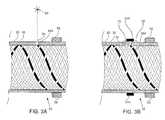
- Fig. 3Ais a schematic diagram illustrating formation of a via
- Fig. 3Bis a schematic diagram illustrating connection of an electrode to a conducting wire of tubing using the via, according to embodiments of the present invention
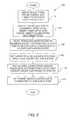
- Fig. 4shows a flow chart of a procedure for attaching an electrode to tubing, according to an embodiment of the present invention.
- Fig. 5shows a flow chart of a procedure for attaching an electrode to tubing, according to an alternative embodiment of the present invention.
- An embodiment of the present inventionprovides a tubular braid, typically for use as part of a medical catheter.
- the braidcomprises a multiplicity of supporting wires, as well as one or more conducting wires, and the braid is covered by a sheath, typically a biocompatible sheath.
- the supporting wiresprovide structural rigidity to the braid, and the conducting wires enable signals to be transferred along the braid.
- the sheathis typically opaque, so that with illumination external to the sheath, the conducting wire (and the supporting wires) is invisible to the human eye.
- the conducting wiremay be configured to be able to be visually differentiated from the supporting wires, for example by having a different diameter.
- the tubular braidmay be illuminated from a volume internal to the braid, causing the conducting wire and the supporting wires to be visible through the sheath to an eye observing from outside the sheath. The visual differences between the conducting and supporting wires enable the position of the conducting wire to be determined along the length of the braid.
- All the wires of the braid, (the conducting and supporting wires)have substantially the same helical pitch, which is typically determined when the braid is formed. Once a position of the conducting wire has been located, typically near a proximal end of the braid, the value of the pitch may be used to calculate the location of the conducting wire at which the electrode is to be attached, without having to visually track the wire to the distal end location.
- a lasermay be used to drill a via in the sheath at the location, and the electrode attached to the wire using conducting cement inserted into the via.
- FIGs. 1A and 1Bare respectively schematic cross-sectional and side views of a central section 21 of braided probe tubing 20, according to an embodiment of the present invention.
- the side view of the sectionshows tubing 20 in a partially cut-away view.
- Tubing 20is formed by forming a tubular braid 22, on an inner tubular lumen 24.
- Lumen 24encloses an internal generally cylindrical volume 25.
- Braid 22is formed on lumen 24 using a braiding machine, such as is known in the art.
- Braid 22is used to strengthen tubing 20, so that the tubing is relatively inflexible and is torsionally rigid.
- the braidis partially formed from a multiplicity of strong supporting wires 26, herein assumed to comprise stainless steel wires.
- wires 26may be any other material, such as carbon fiber or carbon fiber composite, having physical characteristics similar to those of stainless steel wire.
- Supporting wires 26are also herein termed tubing-support wires.
- tubular braid 22comprises one or more conducting wires, which are integrated as part of the braid as the braid is being formed on the braiding machine.
- conducting wires 28comprise conductors 29 covered by insulation 30 surrounding the conductors.
- conductors 29are substantially similar in dimensions and composition to tubing-support wires 26, differing only in being covered by insulation 30.
- tubing-support wires 26are of stainless steel, conductors 29 are of the same diameter stainless steel.
- conductors 29may differ in dimensions or composition, or in both dimensions and composition, from tubing-support wires 26.
- conductors 29are formed of copper.
- the conducting wiresare configured so that they are able to be visually differentiated from tubing-support wires 26.
- conductors 29are copper
- the insulated copper wiresare configured to have an overall diameter different from tubing-support wires 26.
- any other visual difference between the two types of wiresmay be used, such as the color of the insulation.
- Tubing 20may be used as tubing of a medical catheter, and is assumed to have one or more electrodes attached to a distal end 32 of the tubing.
- Electrode 34Ais illustrated in Fig. 3B , which shows distal end 32.
- Fig. 3Bwhich shows distal end 32.
- Electrodes 34A, 34B, 34Care assumed to be connected to equipment, such as an ablation generator, by respective conducting wires 28A, 28B, 28C.
- Each wire (wires 26 and 28) of braid 22is in the shape of a helix, the helices being geometrically identical by virtue of being formed on the same lumen 24.
- the helicesdiffer by having different translations parallel to an axis 36 of tubing 20, but have identical spatial periods, i.e., pitches, P.
- the pitch of each helixis determined at the time the braid is manufactured by the braiding machine, and can be set, within limits, so that the braid formed is "loose,” having a relatively large pitch, or "tight,” having a relatively small pitch.
- a typical pitchmay be in the approximate range of 1.5 - 8 mm.
- sheath 38which is typically formed from a biocompatible material such as a cross-linked polymer. Sheath 38 is opaque when viewed in illumination external to the sheath, so that under external illumination wires 26 and 28 are invisible to a human eye observing the sheath.
- tubing 20has been formed as described above, i.e., with lumen 24, braid 22, and sheath 38, the tubing is typically cut into sections of a length suitable for forming a catheter.
- a typical section lengthis approximately 1 m.
- Figs. 2A and 2Bshow schematic sectional side views of a section 50 of braided tubing 20 that is used for a catheter, in an alignment stage of production of the catheter, according to an embodiment of the present invention.
- Section 50has distal end 32, and a proximal end 52.
- aligning apparatus 54which comprises a first rotatable chuck 56 and a second rotatable chuck 58, the two chucks having a common axis of rotation and being separated by approximately the length of section 50.
- Section 50is assumed to be held by the two chucks so that it is substantially straight. Once mounted, axis 36 of tubing 20 is congruent with the common axis of the chucks. (Chucks 56 and 58 may conveniently be mounted on a lathe bed, although any other arrangement of two chucks having a common axis and separated by approximately the length of section 50 may be used.)
- Aligning apparatus 54also comprises a traveling microscope 60, which is able to travel by measured amounts in a direction parallel to axis 36.
- a traveling microscope 60which is able to travel by measured amounts in a direction parallel to axis 36.
- the mounting arrangements for microscope 60are not shown in Figs. 2A and 2B .
- wires 26 and 28are separated from each other at proximal end 52, so that all tubing-support wires 26, and all conducting wires 28, are able to be accessed by an operator of apparatus 54. For clarity, only some of the separated wires are shown in the figures.
- Fig. 2Ashows the position of the traveling microscope at the beginning of the alignment stage
- Fig. 2Bshows the travelling microscope at the end of the alignment stage.
- a fiber optic 62is inserted into volume 25, typically along substantially the whole length of section of section 50. Fiber optic 62 is used to illuminate the inside of tubing 20.
- fiber optic 62is configured so that optical illumination injected at the proximal end of the optic exits the optic through the walls of the optic.
- Such a configurationmay be implemented by arranging that fiber optic 62 comprises a single fiber, and that the internal reflection that occurs at the walls of the fiber, rather than being total internal reflection as is usually the case with fiber optics, is partial reflection.
- fiber optic 62comprises a bundle of separate fibers of different lengths, the different lengths being selected so as to at least partially provide the illumination for the inside of tubing 20 through the ends of the separate fibers.
- the separate fibersmay be configured so that either partial or total internal reflection occurs at their walls.
- Fig. 2Aillustrates microscope 60 viewing conducting wire 28A at the proximal end of tubing 20
- Fig. 2Billustrates the microscope viewing conducting wire 28A at the distal end of the tubing.
- Fig. 3Ais a schematic diagram illustrating formation of a via
- Fig. 3Bis a schematic diagram illustrating connection of an electrode to a conducting wire of tubing 20 using the via, according to embodiments of the present invention.
- the figuresillustrate an electrode attachment stage in production of the catheter referred to above.
- a via 64is formed in sheath 38 using a laser 66 which drills the via.
- the viais assumed to penetrate sheath 38 until conducting wire 28A is exposed, i.e., so that insulation 30 surrounding the wire is removed.
- Electrode 34Ais positioned over cement 68, so that when the cement sets the electrode is in contact with the sheath. Electrode 34A is typically in the form of a flat ring or cylinder having an internal diameter substantially equal to the external diameter of the sheath. In some embodiments electrode 34A may be in the form of a split flat ring (or cylinder) which is designed to be clamped, so that the ring closes on clamping, and so the ring clamps onto sheath 38.
- Fig. 4shows a flow chart 80, of a procedure for attaching an electrode to tubing 20, according to an embodiment of the present invention.
- the description of the steps of the flow chartrefers to elements of the tubing illustrated in Figs. 1A - 3B .
- braid 22is formed so that the braid comprises conducting wires 28 and tubing-support wires 26.
- the braidis woven over lumen 24, and opaque sheath 38 is applied to cover the braid and form tubing 20.
- the tubingis then cut to produce section 50, i.e., a section of tubing suitable for producing the catheter.
- section 50is mounted in alignment apparatus 54 by being clamped into chucks 56 and 58.
- section 50is arranged so that at proximal end 52 each of the conducting wires 28, and each of the tubing-support wires 26, are separated from each other, typically by being spread out.
- insulation 30 of conducting wires 28may be removed so that conductors 29 are available for electrical connection.
- fiber optic 62is inserted into volume 25 up to distal end 32, and optical illumination is injected into the proximal end of the fiber optic, typically using a high intensity source such as a halogen lamp. As described above, the optical illumination exits from the fiber optic, rendering wires 26 and 28 visible to microscope 60.
- conducting wire 28Ais to be connected to electrode 34A at a preselected location within distal end 32.
- a conducting wire location step 86microscope 60 is traversed at proximal end 52 until an operator controlling the microscope locates conducting wire 28A. Because conducting wires 28 are configured to be visibly distinct from the tubing-support wires, the operator is able to easily distinguish which are the conducting wires in braid 22. Since the wires have been separated at the proximal end, and since the microscope is being operated at the proximal end, the operator is able to visually distinguish between conducting wires 28A, 28B, and 28C, and thus ensure that it is conducting wire 28A that is imaged by the microscope.
- the position near the proximal end at which conducting wire 28A is locatedis herein termed the initial position.
- a theoretical position at which to drill via 64is calculated.
- the calculationassumes that a distance, X, from the initial position to the theoretical drill position is known, since the latter position corresponds to the required position of the electrode.
- the calculationalso assumes that the pitch P of braid 22 is known.
- N⁇ x p ⁇
- a setup step 90while the interior illumination of tubing 20 is maintained, the travelling microscope is moved by distance X, and chucks 56 and 58 are rotated by angle A. While microscope motion and the chuck rotations are theoretically the correct values for aligning conducting wire 28A with the microscope, in practice the rotations need to be checked, since tubing 20 may undergo some, possibly small, twisting, stretching, and/or sagging (from the horizontal). Thus the microscope motion by distance X, and the chuck rotations A, may be considered coarse alignments.
- the apparatus operatormay perform a fine alignment, observing through microscope 60 to ensure that conducting wire 28A aligns with the microscope.
- the fine alignmenttypically comprises rotating the chucks from the theoretical rotation angle A until alignment is achieved.
- the fine alignmentmay also include small movements of the microscope. The fine alignment ensures that the microscope is aligned with the location in sheath 38 where via 64 is to be drilled.
- a drill step 92laser 66 is aligned to drill at the via location, and the laser is activated to drill via 64.
- Electrode 34Ais then positioned over sheath 38 in contact with the cement, and the cement is allowed to set.
- the setting cementprovides a galvanic contact between the electrode and wire 28A, as well as maintaining the electrode in good mechanical contact with the sheath.
- the above proceduremay be repeated for each different electrode, e.g., electrodes 34B, 34C, that is to be attached to section 50 of the catheter tubing.
- Fig. 5shows a flow chart 100, of a procedure for attaching an electrode to tubing 20, according to an alternative embodiment of the present invention.
- the procedure described by flow chart 100assumes that positions for electrodes at the distal end of section 50 are known, and that each electrode may be connected to any conducting wire 28.
- Steps 102 and 104are respectively substantially the same as steps 82 and 84, described above.
- microscope 60is moved to one of the known distal end positions, where an electrode is to be attached. In this position, section 50 is rotated, using chucks 56 and 58, until one of the conducting wires 28 is imaged by and is aligned with the microscope.
- Steps 108 and 110are respectively substantially the same as steps 92 and 94 described above.
- a measurement step 112the operator of apparatus 54 determines, by measuring resistances between the positioned electrode and the exposed conductors 29 at the proximal end, which of the conducting wires is connected to the electrode.
Landscapes
- Health & Medical Sciences (AREA)
- Engineering & Computer Science (AREA)
- Life Sciences & Earth Sciences (AREA)
- Biomedical Technology (AREA)
- Public Health (AREA)
- General Health & Medical Sciences (AREA)
- Veterinary Medicine (AREA)
- Animal Behavior & Ethology (AREA)
- Heart & Thoracic Surgery (AREA)
- Anesthesiology (AREA)
- Surgery (AREA)
- Pulmonology (AREA)
- Biophysics (AREA)
- Nuclear Medicine, Radiotherapy & Molecular Imaging (AREA)
- Hematology (AREA)
- Cardiology (AREA)
- Otolaryngology (AREA)
- Molecular Biology (AREA)
- Medical Informatics (AREA)
- Plasma & Fusion (AREA)
- Physics & Mathematics (AREA)
- Manufacturing & Machinery (AREA)
- Textile Engineering (AREA)
- Radiology & Medical Imaging (AREA)
- Measurement And Recording Of Electrical Phenomena And Electrical Characteristics Of The Living Body (AREA)
- Media Introduction/Drainage Providing Device (AREA)
- Surgical Instruments (AREA)
Abstract
Description
- The present invention relates generally to tubing, and specifically to tubing reinforced by a braid.
- A wide range of medical procedures involve placing objects, such as sensors, dispensing devices, and implants, within the body. The objects are typically placed within the body with the help of tubing, which is typically as narrow as possible, while having sufficient rigidity to be manipulated within the body. Typically, the tubing may include a braid for providing the rigidity.
U. S. Patent 6,213,995, to Steen, et al. , whose disclosure is incorporated herein by reference, describes a flexible tubing which includes a wall provided with a plurality of braided elements forming a braid within the wall of the tube. The braided elements are stated to include one or more signal transmitting elements and one or more metallic or non-metallic structural elements having structural properties different from the signal transmitting elements.U. S. Patent 7,229,437, to Johnson, et al. , whose disclosure is incorporated herein by reference, describes a catheter having electrically conductive traces and external electrical contacts. The disclosure states that each trace may be in electrical connection with one or more external electrical contacts.- The description above is presented as a general overview of related art in this field and should not be construed as an admission that any of the information it contains constitutes prior art against the present patent application.
- An embodiment of the present invention provides a method, including:
- incorporating a conducting wire into a tubular braid having a multiplicity of supporting wires;
- covering the tubular braid with a sheath;
- identifying a location of the conducting wire within the tubular braid; and
- attaching an electrode through the sheath to the conducting wire at the location.
- Typically, the tubular braid encloses an internal volume, and the sheath is opaque to a human eye when illuminated by radiation external to the sheath, and identifying the location includes: illuminating the tubular braid from the internal volume, so as to render the conducting wire and the supporting wires visible through the sheath; and identifying the location of the conducting wire within the tubular braid while the tubular braid is illuminated from the internal volume. Illuminating the tubular braid may include inserting a fiber optic into the internal volume, and injecting optical illumination into the fiber optic.
- In a disclosed embodiment the conducting wire consists of a helix having a pitch P, and identifying the location of the conducting wire includes identifying an initial position of the conducting wire within the tubular braid, and determining the location of the conducting wire in response to the pitch P. Typically, identifying the location includes determining an angle for rotation of the tubular braid in response to the pitch and the identified initial position.
- In another disclosed embodiment attaching the electrode includes drilling a via through the sheath at the location after identifying the location. Typically, attaching the electrode includes inserting conductive cement into the via, and positioning the electrode in contact with the cement and the sheath.
- In a further disclosed embodiment, the method includes incorporating the tubular braid, the electrode, and the sheath as a medical catheter.
- In a yet further disclosed embodiment, the method includes configuring the conducting wire to be visually differentiated from the supporting wires.
- There is further provided, according to an embodiment of the present invention, apparatus, including:
- a tubular braid having a multiplicity of supporting wires and a conducting wire;
- a sheath covering the tubular braid;
- an identified location of the conducting wire within the tubular braid; and
- an electrode attached through the sheath to the conducting wire at the identified location.
- The present disclosure will be more fully understood from the following detailed description of the embodiments thereof, taken together with the drawings, in which:
Figs. 1A and 1B are respectively schematic cross-sectional and side views of a central section of braided probe tubing, according to an embodiment of the present invention;Figs. 2A and2B show schematic sectional side views of a section of braided tubing that is used for a catheter, in an alignment stage of production of the catheter, according to an embodiment of the present invention;Fig. 3A is a schematic diagram illustrating formation of a via, andFig. 3B is a schematic diagram illustrating connection of an electrode to a conducting wire of tubing using the via, according to embodiments of the present invention;Fig. 4 shows a flow chart of a procedure for attaching an electrode to tubing, according to an embodiment of the present invention; andFig. 5 shows a flow chart of a procedure for attaching an electrode to tubing, according to an alternative embodiment of the present invention.- An embodiment of the present invention provides a tubular braid, typically for use as part of a medical catheter. The braid comprises a multiplicity of supporting wires, as well as one or more conducting wires, and the braid is covered by a sheath, typically a biocompatible sheath. The supporting wires provide structural rigidity to the braid, and the conducting wires enable signals to be transferred along the braid.
- A location of the conducting wire, typically near a distal end of the braid, is identified, and an electrode is attached through the sheath to the conducting wire at the identified location. Signals between the electrode and a proximal end of the braid may then be transferred using the conducting wire.
- The sheath is typically opaque, so that with illumination external to the sheath, the conducting wire (and the supporting wires) is invisible to the human eye. In order to determine the location of the conducting wire, the conducting wire may be configured to be able to be visually differentiated from the supporting wires, for example by having a different diameter. The tubular braid may be illuminated from a volume internal to the braid, causing the conducting wire and the supporting wires to be visible through the sheath to an eye observing from outside the sheath. The visual differences between the conducting and supporting wires enable the position of the conducting wire to be determined along the length of the braid.
- All the wires of the braid, (the conducting and supporting wires) have substantially the same helical pitch, which is typically determined when the braid is formed. Once a position of the conducting wire has been located, typically near a proximal end of the braid, the value of the pitch may be used to calculate the location of the conducting wire at which the electrode is to be attached, without having to visually track the wire to the distal end location.
- To attach the electrode to the conducting wire at the identified location, a laser may be used to drill a via in the sheath at the location, and the electrode attached to the wire using conducting cement inserted into the via.
- Reference is now made to
Figs. 1A and 1B , which are respectively schematic cross-sectional and side views of acentral section 21 ofbraided probe tubing 20, according to an embodiment of the present invention. The side view of the section showstubing 20 in a partially cut-away view.Tubing 20 is formed by forming atubular braid 22, on an innertubular lumen 24.Lumen 24 encloses an internal generallycylindrical volume 25.Braid 22 is formed onlumen 24 using a braiding machine, such as is known in the art. - Braid 22 is used to strengthen
tubing 20, so that the tubing is relatively inflexible and is torsionally rigid. The braid is partially formed from a multiplicity of strong supportingwires 26, herein assumed to comprise stainless steel wires. However,wires 26 may be any other material, such as carbon fiber or carbon fiber composite, having physical characteristics similar to those of stainless steel wire. Supportingwires 26 are also herein termed tubing-support wires. - In addition to tubing-
support wires 26,tubular braid 22 comprises one or more conducting wires, which are integrated as part of the braid as the braid is being formed on the braiding machine. By way of example, in the following description there are assumed to be three substantiallysimilar conducting wires conductors 29 covered byinsulation 30 surrounding the conductors. In someembodiments conductors 29 are substantially similar in dimensions and composition to tubing-support wires 26, differing only in being covered byinsulation 30. Thus, if tubing-support wires 26 are of stainless steel,conductors 29 are of the same diameter stainless steel. - Alternatively,
conductors 29 may differ in dimensions or composition, or in both dimensions and composition, from tubing-support wires 26. For example, in one embodiment,conductors 29 are formed of copper. - Regardless of the dimensions or composition of wires 28, the conducting wires are configured so that they are able to be visually differentiated from tubing-
support wires 26. In the embodiment described above whereinconductors 29 are copper, the insulated copper wires are configured to have an overall diameter different from tubing-support wires 26. However, any other visual difference between the two types of wires may be used, such as the color of the insulation. Tubing 20 may be used as tubing of a medical catheter, and is assumed to have one or more electrodes attached to adistal end 32 of the tubing. In the present application, by way of example, three substantiallysimilar electrodes 34A, 34B, 34C, (the number of electrodes corresponding to the number of conducting wires 28) also referred to generically herein aselectrodes 34, are assumed to be attached to the tubing. (Electrode 34A is illustrated inFig. 3B , which showsdistal end 32.) Those having ordinary skill in the art will be able to adapt the description herein for tubing with other numbers of attached electrodes, and for numbers of electrodes which are not the same as the number of wires 28. The latter case may occur, for example, if one of wires 28 is to connect to apparatus, such as a coil or a semiconductor device, withintubing 20 at its distal end.Electrodes 34A, 34B, 34C are assumed to be connected to equipment, such as an ablation generator, byrespective conducting wires - Each wire (
wires 26 and 28) ofbraid 22 is in the shape of a helix, the helices being geometrically identical by virtue of being formed on thesame lumen 24. The helices differ by having different translations parallel to anaxis 36 oftubing 20, but have identical spatial periods, i.e., pitches, P. The pitch of each helix is determined at the time the braid is manufactured by the braiding machine, and can be set, within limits, so that the braid formed is "loose," having a relatively large pitch, or "tight," having a relatively small pitch. A typical pitch may be in the approximate range of 1.5 - 8 mm. - After formation of
braid 22 onlumen 24, the braid is covered by asheath 38 which is typically formed from a biocompatible material such as a cross-linked polymer.Sheath 38 is opaque when viewed in illumination external to the sheath, so that underexternal illumination wires 26 and 28 are invisible to a human eye observing the sheath. - Once
tubing 20 has been formed as described above, i.e., withlumen 24,braid 22, andsheath 38, the tubing is typically cut into sections of a length suitable for forming a catheter. A typical section length is approximately 1 m. Figs. 2A and2B show schematic sectional side views of asection 50 ofbraided tubing 20 that is used for a catheter, in an alignment stage of production of the catheter, according to an embodiment of the present invention. Apart from the differences described below, elements indicated by the same reference numerals forsection 50 and tubing 20 (Figs. 1A, 1B ) are generally similar in construction and in operation.Section 50 hasdistal end 32, and aproximal end 52. By way of example,section 50 is assumed to be mounted in aligningapparatus 54, which comprises a firstrotatable chuck 56 and a secondrotatable chuck 58, the two chucks having a common axis of rotation and being separated by approximately the length ofsection 50.Section 50 is assumed to be held by the two chucks so that it is substantially straight. Once mounted,axis 36 oftubing 20 is congruent with the common axis of the chucks. (Chucks section 50 may be used.)- Aligning
apparatus 54 also comprises a travelingmicroscope 60, which is able to travel by measured amounts in a direction parallel toaxis 36. For simplicity, the mounting arrangements formicroscope 60 are not shown inFigs. 2A and2B . - In the alignment stage referred to above,
wires 26 and 28 are separated from each other atproximal end 52, so that all tubing-support wires 26, and all conducting wires 28, are able to be accessed by an operator ofapparatus 54. For clarity, only some of the separated wires are shown in the figures. Fig. 2A shows the position of the traveling microscope at the beginning of the alignment stage, andFig. 2B shows the travelling microscope at the end of the alignment stage. In the alignment stage, afiber optic 62 is inserted intovolume 25, typically along substantially the whole length of section ofsection 50.Fiber optic 62 is used to illuminate the inside oftubing 20. In order to accomplish this,fiber optic 62 is configured so that optical illumination injected at the proximal end of the optic exits the optic through the walls of the optic. Such a configuration may be implemented by arranging thatfiber optic 62 comprises a single fiber, and that the internal reflection that occurs at the walls of the fiber, rather than being total internal reflection as is usually the case with fiber optics, is partial reflection. Alternatively or additionally,fiber optic 62 comprises a bundle of separate fibers of different lengths, the different lengths being selected so as to at least partially provide the illumination for the inside oftubing 20 through the ends of the separate fibers. The separate fibers may be configured so that either partial or total internal reflection occurs at their walls.- The internal illumination from the fiber optic renders the wires of
braid 22 visible, throughsheath 38, to the human eye, typically usingmicroscope 60.Fig. 2A illustratesmicroscope 60viewing conducting wire 28A at the proximal end oftubing 20, andFig. 2B illustrates the microscopeviewing conducting wire 28A at the distal end of the tubing. - The alignment stage illustrated by
Figs. 2A and2B , and the identification of conductingwire 28A using microscope 60, is described in more detail in the flow chart ofFig. 4 . Fig. 3A is a schematic diagram illustrating formation of a via, andFig. 3B is a schematic diagram illustrating connection of an electrode to a conducting wire oftubing 20 using the via, according to embodiments of the present invention. The figures illustrate an electrode attachment stage in production of the catheter referred to above. In the beginning of the electrode attachment stage (Fig. 3A ) a via 64 is formed insheath 38 using alaser 66 which drills the via. The via is assumed to penetratesheath 38 until conductingwire 28A is exposed, i.e., so thatinsulation 30 surrounding the wire is removed.- Once via 64 has been produced, in the end of the attachment stage (
Fig. 3B ) conductingcement 68 is inserted into the via so as also to cover anouter wall 70 ofsheath 38.Electrode 34A is positioned overcement 68, so that when the cement sets the electrode is in contact with the sheath.Electrode 34A is typically in the form of a flat ring or cylinder having an internal diameter substantially equal to the external diameter of the sheath. In some embodiments electrode 34A may be in the form of a split flat ring (or cylinder) which is designed to be clamped, so that the ring closes on clamping, and so the ring clamps ontosheath 38. Fig. 4 shows aflow chart 80, of a procedure for attaching an electrode totubing 20, according to an embodiment of the present invention. The description of the steps of the flow chart refers to elements of the tubing illustrated inFigs. 1A - 3B .- In a
tubing formation step 82,braid 22 is formed so that the braid comprises conducting wires 28 and tubing-support wires 26. The braid is woven overlumen 24, andopaque sheath 38 is applied to cover the braid andform tubing 20. The tubing is then cut to producesection 50, i.e., a section of tubing suitable for producing the catheter. - In an
alignment step 84,section 50 is mounted inalignment apparatus 54 by being clamped intochucks section 50 is arranged so that atproximal end 52 each of the conducting wires 28, and each of the tubing-support wires 26, are separated from each other, typically by being spread out. In addition,insulation 30 of conducting wires 28 may be removed so thatconductors 29 are available for electrical connection. - Once
section 50 has been set up inapparatus 54,fiber optic 62 is inserted intovolume 25 up todistal end 32, and optical illumination is injected into the proximal end of the fiber optic, typically using a high intensity source such as a halogen lamp. As described above, the optical illumination exits from the fiber optic,rendering wires 26 and 28 visible tomicroscope 60. - The following description assumes that conducting
wire 28A is to be connected toelectrode 34A at a preselected location withindistal end 32. - In a conducting
wire location step 86,microscope 60 is traversed atproximal end 52 until an operator controlling the microscope locates conductingwire 28A. Because conducting wires 28 are configured to be visibly distinct from the tubing-support wires, the operator is able to easily distinguish which are the conducting wires inbraid 22. Since the wires have been separated at the proximal end, and since the microscope is being operated at the proximal end, the operator is able to visually distinguish between conductingwires wire 28A that is imaged by the microscope. The position near the proximal end at whichconducting wire 28A is located is herein termed the initial position. - In a
calculation step 88, a theoretical position at which to drill via 64 is calculated. The calculation assumes that a distance, X, from the initial position to the theoretical drill position is known, since the latter position corresponds to the required position of the electrode. The calculation also assumes that the pitch P ofbraid 22 is known. In this case the number N of complete pitches to the theoretical position is given by equation (1):
- The theoretical position is typically not a whole number of pitches, in which case there is a fraction F, 0 < F < 1, of a pitch between the position of the last whole pitch and the theoretical position. Equation (2) gives F:

- To find the correct theoretical position at which to drill, an angle A by which
section 50 needs to be rotated is given by:
- In a
setup step 90, while the interior illumination oftubing 20 is maintained, the travelling microscope is moved by distance X, and chucks 56 and 58 are rotated by angle A. While microscope motion and the chuck rotations are theoretically the correct values for aligningconducting wire 28A with the microscope, in practice the rotations need to be checked, sincetubing 20 may undergo some, possibly small, twisting, stretching, and/or sagging (from the horizontal). Thus the microscope motion by distance X, and the chuck rotations A, may be considered coarse alignments. - After the coarse alignments have been implemented, the apparatus operator may perform a fine alignment, observing through
microscope 60 to ensure that conductingwire 28A aligns with the microscope. The fine alignment typically comprises rotating the chucks from the theoretical rotation angle A until alignment is achieved. The fine alignment may also include small movements of the microscope. The fine alignment ensures that the microscope is aligned with the location insheath 38 where via 64 is to be drilled. - In a
drill step 92,laser 66 is aligned to drill at the via location, and the laser is activated to drill via 64. - In an
electrode assembly step 94, once via 64 has been formed, it is filled with conductingcement 68, which is typically biocompatible.Electrode 34A is then positioned oversheath 38 in contact with the cement, and the cement is allowed to set. The setting cement provides a galvanic contact between the electrode andwire 28A, as well as maintaining the electrode in good mechanical contact with the sheath. - The above procedure may be repeated for each different electrode, e.g., electrodes 34B, 34C, that is to be attached to
section 50 of the catheter tubing. - The procedure described by
flow chart 80 assumes that a particular conducting wire is connected to a particular electrode. An alternative procedure, where an electrode is connected to any conducting wire, is described below, with reference toFig. 5 . Fig. 5 shows aflow chart 100, of a procedure for attaching an electrode totubing 20, according to an alternative embodiment of the present invention. The procedure described byflow chart 100 assumes that positions for electrodes at the distal end ofsection 50 are known, and that each electrode may be connected to any conducting wire 28.Steps steps - In a set up
step 106,microscope 60 is moved to one of the known distal end positions, where an electrode is to be attached. In this position,section 50 is rotated, usingchucks Steps steps - In a
measurement step 112, the operator ofapparatus 54 determines, by measuring resistances between the positioned electrode and the exposedconductors 29 at the proximal end, which of the conducting wires is connected to the electrode. - The procedure described above may be repeated for all subsequent electrodes that are to be positioned at the distal end, except for the following difference:
- In
step 106, in aligning subsequent conductors, the operator of the microscope should ensure that a conductor that has already been connected to an electrode is not the one aligned with the microscope. Typically, the operator may ensure this by visual inspection of the conducting wires. The visual inspection ensures that a conductor, once connected to one electrode, is not connected to a second electrode. - It will be appreciated that the embodiments described above are cited by way of example, and that the present invention is not limited to what has been particularly shown and described hereinabove. Rather, the scope of the present invention includes both combinations and subcombinations of the various features described hereinabove, as well as variations and modifications thereof which would occur to persons skilled in the art upon reading the foregoing description and which are not disclosed in the prior art.


Claims (15)
- A method, comprising:incorporating a conducting wire into a tubular braid comprising a multiplicity of supporting wires;covering the tubular braid with a sheath;identifying a location of the conducting wire within the tubular braid; andattaching an electrode through the sheath to the conducting wire at the location.
- The method according to claim 1, wherein attaching the electrode comprises drilling a via through the sheath at the location after identifying the location.
- The method according to claim 2, wherein attaching the electrode comprises inserting conductive cement into the via, and positioning the electrode in contact with the cement and the sheath.
- The method according to claim 1, and comprising incorporating the tubular braid, the electrode, and the sheath as a medical catheter.
- The method according to claim 1, and comprising configuring the conducting wire to be visually differentiated from the supporting wires.
- Apparatus, comprising:a tubular braid comprising a multiplicity of supporting wires and a conducting wire;a sheath covering the tubular braid;an identified location of the conducting wire within the tubular braid; andan electrode attached through the sheath to the conducting wire at the identified location.
- The method according to claim 1 or the apparatus according to claim 6, wherein the tubular braid encloses an internal volume, and wherein the sheath is opaque to a human eye when illuminated by radiation external to the sheath, and wherein identifying the location comprises:illuminating the tubular braid from the internal volume, so as to render the conducting wire and the supporting wires visible through the sheath; andidentifying the location of the conducting wire within the tubular braid while the tubular braid is illuminated from the internal volume.
- The method according to claim 7, wherein illuminating the tubular braid comprises inserting a fiber optic into the internal volume, and injecting optical illumination into the fiber optic.
- The apparatus according to claim 7, and comprising a fiber optic configured to be inserted into the internal volume, and wherein illuminating the tubular braid comprises injecting optical illumination into the fiber optic.
- The method according to claim 1 or the apparatus according to claim 7, wherein the conducting wire comprises a helix having a pitch P, and wherein identifying the location of the conducting wire comprises identifying an initial position of the conducting wire within the tubular braid, and determining the location of the conducting wire in response to the pitch P.
- The method or the apparatus according to claim 10, wherein identifying the location comprises determining an angle for rotation of the tubular braid in response to the pitch and the identified initial position.
- The apparatus according to claim 7, wherein attaching the electrode comprises drilling a via through the sheath at the location after identifying the location.
- The apparatus according to claim 12, wherein attaching the electrode comprises inserting conductive cement into the via, and positioning the electrode in contact with the cement and the sheath.
- The apparatus according to claim 7, and comprising incorporating the tubular braid, the electrode, and the sheath as a medical catheter.
- The apparatus according to claim 7, wherein the conducting wire is able to be visually differentiated from the supporting wires.
Priority Applications (1)
| Application Number | Priority Date | Filing Date | Title |
|---|---|---|---|
| EP18161063.5AEP3351199B1 (en) | 2010-12-29 | 2011-12-28 | Braid with integrated signal conductors |
Applications Claiming Priority (1)
| Application Number | Priority Date | Filing Date | Title |
|---|---|---|---|
| US12/980,748US9717553B2 (en) | 2010-12-29 | 2010-12-29 | Braid with integrated signal conductors |
Related Child Applications (2)
| Application Number | Title | Priority Date | Filing Date |
|---|---|---|---|
| EP18161063.5ADivisionEP3351199B1 (en) | 2010-12-29 | 2011-12-28 | Braid with integrated signal conductors |
| EP18161063.5ADivision-IntoEP3351199B1 (en) | 2010-12-29 | 2011-12-28 | Braid with integrated signal conductors |
Publications (2)
| Publication Number | Publication Date |
|---|---|
| EP2471480A1true EP2471480A1 (en) | 2012-07-04 |
| EP2471480B1 EP2471480B1 (en) | 2018-09-05 |
Family
ID=45470374
Family Applications (2)
| Application Number | Title | Priority Date | Filing Date |
|---|---|---|---|
| EP11195886.4AActiveEP2471480B1 (en) | 2010-12-29 | 2011-12-28 | Braid with integrated signal conductors |
| EP18161063.5AActiveEP3351199B1 (en) | 2010-12-29 | 2011-12-28 | Braid with integrated signal conductors |
Family Applications After (1)
| Application Number | Title | Priority Date | Filing Date |
|---|---|---|---|
| EP18161063.5AActiveEP3351199B1 (en) | 2010-12-29 | 2011-12-28 | Braid with integrated signal conductors |
Country Status (8)
| Country | Link |
|---|---|
| US (1) | US9717553B2 (en) |
| EP (2) | EP2471480B1 (en) |
| JP (1) | JP5921881B2 (en) |
| CN (1) | CN102551672B (en) |
| AU (1) | AU2011265497B2 (en) |
| CA (1) | CA2762201C (en) |
| ES (1) | ES2688797T3 (en) |
| IL (1) | IL216808B (en) |
Cited By (8)
| Publication number | Priority date | Publication date | Assignee | Title |
|---|---|---|---|---|
| WO2014182806A1 (en)* | 2013-05-07 | 2014-11-13 | St. Jude Medical, Atrial Fibrillation Division, Inc. | Guiding medical devices and associated methods of manufacturing |
| EP2865414A1 (en)* | 2013-10-25 | 2015-04-29 | Biosense Webster (Israel), Ltd. | Connection of electrodes to wires coiled on a core |
| US9259813B2 (en) | 2007-07-18 | 2016-02-16 | St. Jude Medical, Atrial Fibrillation Division, Inc. | Catheter and introducer catheter having torque transfer layer and method of manufacture |
| EP3215209A4 (en)* | 2014-11-05 | 2018-06-13 | Clph, Llc | Catheter devices and methods for making them |
| CN110290739A (en)* | 2017-06-01 | 2019-09-27 | 奥林巴斯株式会社 | Medical Devices pipe |
| US10575743B2 (en) | 2013-04-11 | 2020-03-03 | Biosense Webster (Israel) Ltd. | High electrode density basket catheter |
| US10582869B2 (en) | 2013-04-11 | 2020-03-10 | Biosense Webster (Israel) Ltd. | Connection of electrodes to wires coiled on a core |
| EP3673785A1 (en)* | 2018-12-24 | 2020-07-01 | Biosense Webster (Israel) Ltd. | Non-invasive measurement of the pitch of a braid |
Families Citing this family (18)
| Publication number | Priority date | Publication date | Assignee | Title |
|---|---|---|---|---|
| JP5885302B2 (en)* | 2012-10-29 | 2016-03-15 | 日本ライフライン株式会社 | Medical equipment |
| US9993291B2 (en) | 2013-02-07 | 2018-06-12 | Shanghai Golden Leaf Med Tec Co., Ltd | Radio frequency ablation method, system and radio frequency ablation device thereof |
| US10071222B2 (en)* | 2013-03-16 | 2018-09-11 | Clph, Llc | Electrode catheters and methods for making them |
| EP3082930B1 (en)* | 2013-12-20 | 2019-07-17 | Boston Scientific Scimed, Inc. | Integrated catheter system |
| US9986949B2 (en)* | 2014-03-05 | 2018-06-05 | Biosense Webster (Israel) Ltd. | Multi-arm catheter with signal transmission over braid wires |
| CN106232043B (en) | 2014-04-24 | 2019-07-23 | 美敦力阿迪安卢森堡有限公司 | Nerve modulation conduit and relevant system and method with braiding axle |
| CA2985516A1 (en)* | 2015-05-12 | 2016-11-17 | Mir Imran | Device, system and methods for measurement of pressures in the urinary tract |
| US10589060B2 (en) | 2016-12-21 | 2020-03-17 | Biosense Webster (Israel) Ltd. | Extrusion with preferential bend axis |
| JP2018133139A (en)* | 2017-02-13 | 2018-08-23 | 住友電装株式会社 | Protective member, high voltage cable for vehicle, and wire harness |
| EP3606457A4 (en)* | 2017-04-03 | 2021-04-21 | Broncus Medical Inc. | ELECTROSURGICAL ACCESS SHEATH |
| TWI683678B (en) | 2017-07-31 | 2020-02-01 | 美商艾克斯公司 | Steerable medical device with braided structure and the preparing method thereof |
| WO2020067491A1 (en)* | 2018-09-27 | 2020-04-02 | テルモ株式会社 | Medical device |
| CN109613024B (en)* | 2018-11-12 | 2021-04-27 | 深圳中科飞测科技股份有限公司 | Motion platform and working method thereof, detection equipment and detection method |
| US20200168360A1 (en)* | 2018-11-27 | 2020-05-28 | Neuwave Medical, Inc. | Systems and methods for energy delivery |
| US10512753B1 (en)* | 2018-12-07 | 2019-12-24 | John Nguyen | Composite catheter shafts and methods and apparatus for making the same |
| JP6789559B1 (en)* | 2020-02-12 | 2020-11-25 | リバーフィールド株式会社 | Insulated shaft and high frequency forceps |
| IT202200007616A1 (en)* | 2022-04-15 | 2023-10-15 | Eurosets Srl | CANNULA FOR DRAINAGE AND/OR REINFUSION OF BLOOD FLUIDS |
| WO2024157343A1 (en)* | 2023-01-24 | 2024-08-02 | Swcc株式会社 | Catheter and production method therefor |
Citations (9)
| Publication number | Priority date | Publication date | Assignee | Title |
|---|---|---|---|---|
| WO1999015219A1 (en)* | 1997-09-25 | 1999-04-01 | Scimed Life Systems, Inc. | Catheter having a high tensile strength braid wire constraint and method of manufacture |
| WO1999049932A1 (en)* | 1998-03-30 | 1999-10-07 | Boston Scientific Corporation | Catheter carrying an electrode and methods of assembly |
| US6002956A (en)* | 1995-05-23 | 1999-12-14 | Cardima, Inc. | Method of treating using an over-the-wire EP catheter |
| US6213995B1 (en)* | 1999-08-31 | 2001-04-10 | Phelps Dodge High Performance Conductors Of Sc And Ga, Inc. | Flexible tubing with braided signal transmission elements |
| US20050065508A1 (en)* | 2003-09-22 | 2005-03-24 | Michael Johnson | Medical device having integral traces and formed electrodes |
| WO2006012671A1 (en)* | 2004-08-05 | 2006-02-09 | Cathrx Ltd | A process of manufacturing an electrical lead |
| EP1916011A1 (en)* | 2000-10-20 | 2008-04-30 | CathRx Ltd | An electrical lead |
| EP1970019A1 (en)* | 2007-03-12 | 2008-09-17 | Cathrx Ltd | A medical use electrical lead including a radio opaque marker |
| WO2010063078A1 (en)* | 2008-12-05 | 2010-06-10 | Cathrx Ltd | An irrigation catheter and a method of fabricating |
Family Cites Families (10)
| Publication number | Priority date | Publication date | Assignee | Title |
|---|---|---|---|---|
| US5183593A (en)* | 1989-11-14 | 1993-02-02 | Poly-Flex Circuits, Inc. | Electrically conductive cement |
| US5555618A (en)* | 1993-10-12 | 1996-09-17 | Arrow International Investment Corp. | Method of making electrode-carrying catheter |
| US5782760A (en)* | 1995-05-23 | 1998-07-21 | Cardima, Inc. | Over-the-wire EP catheter |
| US6149574A (en)* | 1997-12-19 | 2000-11-21 | Radiance Medical Systems, Inc. | Dual catheter radiation delivery system |
| JP2000036225A (en) | 1998-07-21 | 2000-02-02 | Hitachi Cable Ltd | Cord switch |
| US20040236231A1 (en)* | 2003-05-23 | 2004-11-25 | Embro Corporation | Light catheter for illuminating tissue structures |
| CN101001663A (en)* | 2004-08-05 | 2007-07-18 | 导管治疗有限公司 | Method for making electrical conductors |
| US20070073160A1 (en)* | 2005-09-13 | 2007-03-29 | Children's Medical Center Corporation | Light-guided transluminal catheter |
| EP2093011A1 (en)* | 2008-02-22 | 2009-08-26 | National University of Ireland Galway | A method and apparatus for detecting hole breakthrough in a laser drilling process, using an optical fibre |
| US8864744B2 (en)* | 2009-02-25 | 2014-10-21 | St. Jude Medical, Atrial Fibrillation Division, Inc. | Medical device having laminate-coated braid assembly |
- 2010
- 2010-12-29USUS12/980,748patent/US9717553B2/enactiveActive
- 2011
- 2011-12-07ILIL216808Apatent/IL216808B/enactiveIP Right Grant
- 2011-12-15CACA2762201Apatent/CA2762201C/ennot_activeExpired - Fee Related
- 2011-12-22AUAU2011265497Apatent/AU2011265497B2/ennot_activeCeased
- 2011-12-28EPEP11195886.4Apatent/EP2471480B1/enactiveActive
- 2011-12-28ESES11195886.4Tpatent/ES2688797T3/enactiveActive
- 2011-12-28EPEP18161063.5Apatent/EP3351199B1/enactiveActive
- 2011-12-28JPJP2011288674Apatent/JP5921881B2/enactiveActive
- 2011-12-29CNCN201110462047.6Apatent/CN102551672B/enactiveActive
Patent Citations (9)
| Publication number | Priority date | Publication date | Assignee | Title |
|---|---|---|---|---|
| US6002956A (en)* | 1995-05-23 | 1999-12-14 | Cardima, Inc. | Method of treating using an over-the-wire EP catheter |
| WO1999015219A1 (en)* | 1997-09-25 | 1999-04-01 | Scimed Life Systems, Inc. | Catheter having a high tensile strength braid wire constraint and method of manufacture |
| WO1999049932A1 (en)* | 1998-03-30 | 1999-10-07 | Boston Scientific Corporation | Catheter carrying an electrode and methods of assembly |
| US6213995B1 (en)* | 1999-08-31 | 2001-04-10 | Phelps Dodge High Performance Conductors Of Sc And Ga, Inc. | Flexible tubing with braided signal transmission elements |
| EP1916011A1 (en)* | 2000-10-20 | 2008-04-30 | CathRx Ltd | An electrical lead |
| US20050065508A1 (en)* | 2003-09-22 | 2005-03-24 | Michael Johnson | Medical device having integral traces and formed electrodes |
| WO2006012671A1 (en)* | 2004-08-05 | 2006-02-09 | Cathrx Ltd | A process of manufacturing an electrical lead |
| EP1970019A1 (en)* | 2007-03-12 | 2008-09-17 | Cathrx Ltd | A medical use electrical lead including a radio opaque marker |
| WO2010063078A1 (en)* | 2008-12-05 | 2010-06-10 | Cathrx Ltd | An irrigation catheter and a method of fabricating |
Cited By (14)
| Publication number | Priority date | Publication date | Assignee | Title |
|---|---|---|---|---|
| US9492636B2 (en) | 2007-07-18 | 2016-11-15 | St. Jude Medical, Atrial Fibrillation Division, Inc. | Catheter and introducer catheter having torque transfer layer and method of manufacture |
| US10130791B2 (en) | 2007-07-18 | 2018-11-20 | St. Jude Medical, Atrial Fibrillation Division, Inc. | Catheter and introducer catheter having torque transfer layer and method of manufacture |
| US9259813B2 (en) | 2007-07-18 | 2016-02-16 | St. Jude Medical, Atrial Fibrillation Division, Inc. | Catheter and introducer catheter having torque transfer layer and method of manufacture |
| US10602947B2 (en) | 2013-04-11 | 2020-03-31 | Biosense Webster (Israel), Ltd. | High density electrode structure |
| US10575743B2 (en) | 2013-04-11 | 2020-03-03 | Biosense Webster (Israel) Ltd. | High electrode density basket catheter |
| US10582869B2 (en) | 2013-04-11 | 2020-03-10 | Biosense Webster (Israel) Ltd. | Connection of electrodes to wires coiled on a core |
| EP3685878A1 (en)* | 2013-04-11 | 2020-07-29 | Biosense Webster (Israel) Ltd. | High density electrode structure |
| WO2014182806A1 (en)* | 2013-05-07 | 2014-11-13 | St. Jude Medical, Atrial Fibrillation Division, Inc. | Guiding medical devices and associated methods of manufacturing |
| US10625044B2 (en) | 2013-05-07 | 2020-04-21 | St. Jude Medical, Atrial Fibrilation Division, Inc. | Guiding medical devices and associated methods of manufacturing |
| EP2865414A1 (en)* | 2013-10-25 | 2015-04-29 | Biosense Webster (Israel), Ltd. | Connection of electrodes to wires coiled on a core |
| EP3215209A4 (en)* | 2014-11-05 | 2018-06-13 | Clph, Llc | Catheter devices and methods for making them |
| EP4218882A3 (en)* | 2014-11-05 | 2023-08-16 | Clph, Llc | Catheter devices and methods for making them |
| CN110290739A (en)* | 2017-06-01 | 2019-09-27 | 奥林巴斯株式会社 | Medical Devices pipe |
| EP3673785A1 (en)* | 2018-12-24 | 2020-07-01 | Biosense Webster (Israel) Ltd. | Non-invasive measurement of the pitch of a braid |
Also Published As
| Publication number | Publication date |
|---|---|
| EP3351199B1 (en) | 2022-12-28 |
| EP2471480B1 (en) | 2018-09-05 |
| CA2762201A1 (en) | 2012-06-29 |
| ES2688797T3 (en) | 2018-11-07 |
| CN102551672B (en) | 2016-08-10 |
| AU2011265497B2 (en) | 2015-02-26 |
| US20120172714A1 (en) | 2012-07-05 |
| CN102551672A (en) | 2012-07-11 |
| IL216808A0 (en) | 2012-01-31 |
| EP3351199A1 (en) | 2018-07-25 |
| US9717553B2 (en) | 2017-08-01 |
| IL216808B (en) | 2019-09-26 |
| JP5921881B2 (en) | 2016-05-24 |
| CA2762201C (en) | 2019-02-26 |
| JP2012139503A (en) | 2012-07-26 |
| AU2011265497A1 (en) | 2012-07-19 |
Similar Documents
| Publication | Publication Date | Title |
|---|---|---|
| EP2471480B1 (en) | Braid with integrated signal conductors | |
| US6203493B1 (en) | Attachment with one or more sensors for precise position determination of endoscopes | |
| JP3994053B2 (en) | Surgical needle and surgical instrument | |
| JP2022545646A (en) | Shape sensing system and method for medical devices | |
| US20170319049A1 (en) | System for Controlling an Instrument Using Shape Sensors | |
| CA3071473C (en) | Endoscope device | |
| AU2004214572B2 (en) | Inserting shape detecting probe | |
| EP2723434B1 (en) | Composite fiber guidewires | |
| EP4404861A1 (en) | Shape sensing reference frame | |
| JP2014501557A5 (en) | ||
| CN210784247U (en) | Rotary control damping piece and control handle of electronic endoscope system | |
| CN105431194A (en) | Actively tracked medical devices | |
| CN102395312A (en) | Needle with integrated fibers in the cutting facets of the bevel | |
| WO2023212098A1 (en) | Conductor incorporated fiber enabled medical systems | |
| CN109770832B (en) | Superfine electronic endoscope system with guiding function and using method thereof | |
| EP2358265A1 (en) | Needle with integrated fibers | |
| EP2936070A1 (en) | Position detection sensor and manipulator | |
| JP2022056405A (en) | Circular navigation catheter with inductive navigation sensor mounted on the surface | |
| DE50112675D1 (en) | PROBE FOR DIELECTRIC AND OPTICAL DIAGNOSTICS | |
| US20140066715A1 (en) | Harness for medical device and method for assembling medical device | |
| JP3615169B2 (en) | Insertion shape detection probe | |
| JP5148070B2 (en) | Imaging device | |
| CN116999011B (en) | Endoscope pipeline capable of being bent at will | |
| CN222828572U (en) | Endoscope tip and endoscope | |
| KR101447670B1 (en) | Cartheter having wide angle function |
Legal Events
| Date | Code | Title | Description |
|---|---|---|---|
| AK | Designated contracting states | Kind code of ref document:A1 Designated state(s):AL AT BE BG CH CY CZ DE DK EE ES FI FR GB GR HR HU IE IS IT LI LT LU LV MC MK MT NL NO PL PT RO RS SE SI SK SM TR | |
| AX | Request for extension of the european patent | Extension state:BA ME | |
| PUAI | Public reference made under article 153(3) epc to a published international application that has entered the european phase | Free format text:ORIGINAL CODE: 0009012 | |
| 17P | Request for examination filed | Effective date:20121220 | |
| 17Q | First examination report despatched | Effective date:20130408 | |
| GRAP | Despatch of communication of intention to grant a patent | Free format text:ORIGINAL CODE: EPIDOSNIGR1 | |
| STAA | Information on the status of an ep patent application or granted ep patent | Free format text:STATUS: GRANT OF PATENT IS INTENDED | |
| INTG | Intention to grant announced | Effective date:20180418 | |
| GRAS | Grant fee paid | Free format text:ORIGINAL CODE: EPIDOSNIGR3 | |
| GRAA | (expected) grant | Free format text:ORIGINAL CODE: 0009210 | |
| STAA | Information on the status of an ep patent application or granted ep patent | Free format text:STATUS: THE PATENT HAS BEEN GRANTED | |
| RAP1 | Party data changed (applicant data changed or rights of an application transferred) | Owner name:BIOSENSE WEBSTER (ISRAEL) LTD. | |
| AK | Designated contracting states | Kind code of ref document:B1 Designated state(s):AL AT BE BG CH CY CZ DE DK EE ES FI FR GB GR HR HU IE IS IT LI LT LU LV MC MK MT NL NO PL PT RO RS SE SI SK SM TR | |
| REG | Reference to a national code | Ref country code:GB Ref legal event code:FG4D | |
| REG | Reference to a national code | Ref country code:CH Ref legal event code:EP | |
| REG | Reference to a national code | Ref country code:AT Ref legal event code:REF Ref document number:1036927 Country of ref document:AT Kind code of ref document:T Effective date:20180915 | |
| REG | Reference to a national code | Ref country code:IE Ref legal event code:FG4D | |
| REG | Reference to a national code | Ref country code:DE Ref legal event code:R096 Ref document number:602011051713 Country of ref document:DE | |
| REG | Reference to a national code | Ref country code:ES Ref legal event code:FG2A Ref document number:2688797 Country of ref document:ES Kind code of ref document:T3 Effective date:20181107 | |
| REG | Reference to a national code | Ref country code:NL Ref legal event code:FP | |
| REG | Reference to a national code | Ref country code:LT Ref legal event code:MG4D | |
| PG25 | Lapsed in a contracting state [announced via postgrant information from national office to epo] | Ref country code:LT Free format text:LAPSE BECAUSE OF FAILURE TO SUBMIT A TRANSLATION OF THE DESCRIPTION OR TO PAY THE FEE WITHIN THE PRESCRIBED TIME-LIMIT Effective date:20180905 Ref country code:RS Free format text:LAPSE BECAUSE OF FAILURE TO SUBMIT A TRANSLATION OF THE DESCRIPTION OR TO PAY THE FEE WITHIN THE PRESCRIBED TIME-LIMIT Effective date:20180905 Ref country code:SE Free format text:LAPSE BECAUSE OF FAILURE TO SUBMIT A TRANSLATION OF THE DESCRIPTION OR TO PAY THE FEE WITHIN THE PRESCRIBED TIME-LIMIT Effective date:20180905 Ref country code:NO Free format text:LAPSE BECAUSE OF FAILURE TO SUBMIT A TRANSLATION OF THE DESCRIPTION OR TO PAY THE FEE WITHIN THE PRESCRIBED TIME-LIMIT Effective date:20181205 Ref country code:GR Free format text:LAPSE BECAUSE OF FAILURE TO SUBMIT A TRANSLATION OF THE DESCRIPTION OR TO PAY THE FEE WITHIN THE PRESCRIBED TIME-LIMIT Effective date:20181206 Ref country code:BG Free format text:LAPSE BECAUSE OF FAILURE TO SUBMIT A TRANSLATION OF THE DESCRIPTION OR TO PAY THE FEE WITHIN THE PRESCRIBED TIME-LIMIT Effective date:20181205 Ref country code:FI Free format text:LAPSE BECAUSE OF FAILURE TO SUBMIT A TRANSLATION OF THE DESCRIPTION OR TO PAY THE FEE WITHIN THE PRESCRIBED TIME-LIMIT Effective date:20180905 | |
| REG | Reference to a national code | Ref country code:AT Ref legal event code:MK05 Ref document number:1036927 Country of ref document:AT Kind code of ref document:T Effective date:20180905 | |
| PG25 | Lapsed in a contracting state [announced via postgrant information from national office to epo] | Ref country code:LV Free format text:LAPSE BECAUSE OF FAILURE TO SUBMIT A TRANSLATION OF THE DESCRIPTION OR TO PAY THE FEE WITHIN THE PRESCRIBED TIME-LIMIT Effective date:20180905 Ref country code:AL Free format text:LAPSE BECAUSE OF FAILURE TO SUBMIT A TRANSLATION OF THE DESCRIPTION OR TO PAY THE FEE WITHIN THE PRESCRIBED TIME-LIMIT Effective date:20180905 Ref country code:HR Free format text:LAPSE BECAUSE OF FAILURE TO SUBMIT A TRANSLATION OF THE DESCRIPTION OR TO PAY THE FEE WITHIN THE PRESCRIBED TIME-LIMIT Effective date:20180905 | |
| PG25 | Lapsed in a contracting state [announced via postgrant information from national office to epo] | Ref country code:IS Free format text:LAPSE BECAUSE OF FAILURE TO SUBMIT A TRANSLATION OF THE DESCRIPTION OR TO PAY THE FEE WITHIN THE PRESCRIBED TIME-LIMIT Effective date:20190105 Ref country code:PL Free format text:LAPSE BECAUSE OF FAILURE TO SUBMIT A TRANSLATION OF THE DESCRIPTION OR TO PAY THE FEE WITHIN THE PRESCRIBED TIME-LIMIT Effective date:20180905 Ref country code:EE Free format text:LAPSE BECAUSE OF FAILURE TO SUBMIT A TRANSLATION OF THE DESCRIPTION OR TO PAY THE FEE WITHIN THE PRESCRIBED TIME-LIMIT Effective date:20180905 Ref country code:RO Free format text:LAPSE BECAUSE OF FAILURE TO SUBMIT A TRANSLATION OF THE DESCRIPTION OR TO PAY THE FEE WITHIN THE PRESCRIBED TIME-LIMIT Effective date:20180905 Ref country code:AT Free format text:LAPSE BECAUSE OF FAILURE TO SUBMIT A TRANSLATION OF THE DESCRIPTION OR TO PAY THE FEE WITHIN THE PRESCRIBED TIME-LIMIT Effective date:20180905 Ref country code:CZ Free format text:LAPSE BECAUSE OF FAILURE TO SUBMIT A TRANSLATION OF THE DESCRIPTION OR TO PAY THE FEE WITHIN THE PRESCRIBED TIME-LIMIT Effective date:20180905 | |
| PGFP | Annual fee paid to national office [announced via postgrant information from national office to epo] | Ref country code:ES Payment date:20190102 Year of fee payment:8 | |
| PG25 | Lapsed in a contracting state [announced via postgrant information from national office to epo] | Ref country code:SM Free format text:LAPSE BECAUSE OF FAILURE TO SUBMIT A TRANSLATION OF THE DESCRIPTION OR TO PAY THE FEE WITHIN THE PRESCRIBED TIME-LIMIT Effective date:20180905 Ref country code:SK Free format text:LAPSE BECAUSE OF FAILURE TO SUBMIT A TRANSLATION OF THE DESCRIPTION OR TO PAY THE FEE WITHIN THE PRESCRIBED TIME-LIMIT Effective date:20180905 Ref country code:PT Free format text:LAPSE BECAUSE OF FAILURE TO SUBMIT A TRANSLATION OF THE DESCRIPTION OR TO PAY THE FEE WITHIN THE PRESCRIBED TIME-LIMIT Effective date:20190105 | |
| REG | Reference to a national code | Ref country code:DE Ref legal event code:R097 Ref document number:602011051713 Country of ref document:DE | |
| PLBE | No opposition filed within time limit | Free format text:ORIGINAL CODE: 0009261 | |
| STAA | Information on the status of an ep patent application or granted ep patent | Free format text:STATUS: NO OPPOSITION FILED WITHIN TIME LIMIT | |
| PG25 | Lapsed in a contracting state [announced via postgrant information from national office to epo] | Ref country code:DK Free format text:LAPSE BECAUSE OF FAILURE TO SUBMIT A TRANSLATION OF THE DESCRIPTION OR TO PAY THE FEE WITHIN THE PRESCRIBED TIME-LIMIT Effective date:20180905 | |
| 26N | No opposition filed | Effective date:20190606 | |
| PG25 | Lapsed in a contracting state [announced via postgrant information from national office to epo] | Ref country code:MC Free format text:LAPSE BECAUSE OF FAILURE TO SUBMIT A TRANSLATION OF THE DESCRIPTION OR TO PAY THE FEE WITHIN THE PRESCRIBED TIME-LIMIT Effective date:20180905 Ref country code:LU Free format text:LAPSE BECAUSE OF NON-PAYMENT OF DUE FEES Effective date:20181228 Ref country code:SI Free format text:LAPSE BECAUSE OF FAILURE TO SUBMIT A TRANSLATION OF THE DESCRIPTION OR TO PAY THE FEE WITHIN THE PRESCRIBED TIME-LIMIT Effective date:20180905 | |
| PG25 | Lapsed in a contracting state [announced via postgrant information from national office to epo] | Ref country code:MT Free format text:LAPSE BECAUSE OF NON-PAYMENT OF DUE FEES Effective date:20181228 | |
| PGFP | Annual fee paid to national office [announced via postgrant information from national office to epo] | Ref country code:IE Payment date:20191209 Year of fee payment:9 | |
| PGFP | Annual fee paid to national office [announced via postgrant information from national office to epo] | Ref country code:BE Payment date:20191118 Year of fee payment:9 | |
| PG25 | Lapsed in a contracting state [announced via postgrant information from national office to epo] | Ref country code:TR Free format text:LAPSE BECAUSE OF FAILURE TO SUBMIT A TRANSLATION OF THE DESCRIPTION OR TO PAY THE FEE WITHIN THE PRESCRIBED TIME-LIMIT Effective date:20180905 | |
| PGFP | Annual fee paid to national office [announced via postgrant information from national office to epo] | Ref country code:CH Payment date:20191213 Year of fee payment:9 | |
| PG25 | Lapsed in a contracting state [announced via postgrant information from national office to epo] | Ref country code:MK Free format text:LAPSE BECAUSE OF NON-PAYMENT OF DUE FEES Effective date:20180905 Ref country code:CY Free format text:LAPSE BECAUSE OF FAILURE TO SUBMIT A TRANSLATION OF THE DESCRIPTION OR TO PAY THE FEE WITHIN THE PRESCRIBED TIME-LIMIT Effective date:20180905 Ref country code:HU Free format text:LAPSE BECAUSE OF FAILURE TO SUBMIT A TRANSLATION OF THE DESCRIPTION OR TO PAY THE FEE WITHIN THE PRESCRIBED TIME-LIMIT; INVALID AB INITIO Effective date:20111228 | |
| REG | Reference to a national code | Ref country code:ES Ref legal event code:FD2A Effective date:20210524 | |
| REG | Reference to a national code | Ref country code:CH Ref legal event code:PL | |
| PG25 | Lapsed in a contracting state [announced via postgrant information from national office to epo] | Ref country code:ES Free format text:LAPSE BECAUSE OF NON-PAYMENT OF DUE FEES Effective date:20191229 | |
| REG | Reference to a national code | Ref country code:BE Ref legal event code:MM Effective date:20201231 | |
| PG25 | Lapsed in a contracting state [announced via postgrant information from national office to epo] | Ref country code:IE Free format text:LAPSE BECAUSE OF NON-PAYMENT OF DUE FEES Effective date:20201228 | |
| PG25 | Lapsed in a contracting state [announced via postgrant information from national office to epo] | Ref country code:LI Free format text:LAPSE BECAUSE OF NON-PAYMENT OF DUE FEES Effective date:20201231 Ref country code:CH Free format text:LAPSE BECAUSE OF NON-PAYMENT OF DUE FEES Effective date:20201231 | |
| PG25 | Lapsed in a contracting state [announced via postgrant information from national office to epo] | Ref country code:BE Free format text:LAPSE BECAUSE OF NON-PAYMENT OF DUE FEES Effective date:20201231 | |
| PGFP | Annual fee paid to national office [announced via postgrant information from national office to epo] | Ref country code:NL Payment date:20221114 Year of fee payment:12 | |
| REG | Reference to a national code | Ref country code:NL Ref legal event code:MM Effective date:20240101 | |
| PG25 | Lapsed in a contracting state [announced via postgrant information from national office to epo] | Ref country code:NL Free format text:LAPSE BECAUSE OF NON-PAYMENT OF DUE FEES Effective date:20240101 | |
| PG25 | Lapsed in a contracting state [announced via postgrant information from national office to epo] | Ref country code:NL Free format text:LAPSE BECAUSE OF NON-PAYMENT OF DUE FEES Effective date:20240101 | |
| PGFP | Annual fee paid to national office [announced via postgrant information from national office to epo] | Ref country code:DE Payment date:20241105 Year of fee payment:14 | |
| PGFP | Annual fee paid to national office [announced via postgrant information from national office to epo] | Ref country code:GB Payment date:20241107 Year of fee payment:14 | |
| PGFP | Annual fee paid to national office [announced via postgrant information from national office to epo] | Ref country code:FR Payment date:20241111 Year of fee payment:14 | |
| PGFP | Annual fee paid to national office [announced via postgrant information from national office to epo] | Ref country code:IT Payment date:20241112 Year of fee payment:14 |