EP2468442B1 - Method for producing boreholes - Google Patents
Method for producing boreholesDownload PDFInfo
- Publication number
- EP2468442B1 EP2468442B1EP11193647.2AEP11193647AEP2468442B1EP 2468442 B1EP2468442 B1EP 2468442B1EP 11193647 AEP11193647 AEP 11193647AEP 2468442 B1EP2468442 B1EP 2468442B1
- Authority
- EP
- European Patent Office
- Prior art keywords
- bore
- machining
- tool electrode
- during
- longitudinal axis
- Prior art date
- Legal status (The legal status is an assumption and is not a legal conclusion. Google has not performed a legal analysis and makes no representation as to the accuracy of the status listed.)
- Not-in-force
Links
- 238000004519manufacturing processMethods0.000titleclaimsdescription24
- 238000000034methodMethods0.000claimsdescription85
- 238000003754machiningMethods0.000claimsdescription81
- 230000033001locomotionEffects0.000claimsdescription25
- 238000009760electrical discharge machiningMethods0.000claimsdescription15
- 238000012545processingMethods0.000description21
- 238000012937correctionMethods0.000description12
- 201000002672Miura type epiphyseal chondrodysplasiaDiseases0.000description11
- 238000002347injectionMethods0.000description5
- 239000007924injectionSubstances0.000description5
- 238000005516engineering processMethods0.000description4
- 238000000265homogenisationMethods0.000description3
- 238000005553drillingMethods0.000description2
- 230000003628erosive effectEffects0.000description2
- 238000010438heat treatmentMethods0.000description2
- 239000000463materialSubstances0.000description2
- 238000010002mechanical finishingMethods0.000description2
- 238000002604ultrasonographyMethods0.000description2
- 238000002679ablationMethods0.000description1
- 238000005452bendingMethods0.000description1
- 230000006735deficitEffects0.000description1
- 230000001419dependent effectEffects0.000description1
- 238000013461designMethods0.000description1
- 238000011161developmentMethods0.000description1
- 230000018109developmental processEffects0.000description1
- 239000000446fuelSubstances0.000description1
- 230000013011matingEffects0.000description1
- 230000010355oscillationEffects0.000description1
- 238000003672processing methodMethods0.000description1
- 230000002441reversible effectEffects0.000description1
- 238000000926separation methodMethods0.000description1
- 230000001360synchronised effectEffects0.000description1
Images

Classifications
- B—PERFORMING OPERATIONS; TRANSPORTING
- B24—GRINDING; POLISHING
- B24B—MACHINES, DEVICES, OR PROCESSES FOR GRINDING OR POLISHING; DRESSING OR CONDITIONING OF ABRADING SURFACES; FEEDING OF GRINDING, POLISHING, OR LAPPING AGENTS
- B24B33/00—Honing machines or devices; Accessories therefor
- B24B33/02—Honing machines or devices; Accessories therefor designed for working internal surfaces of revolution, e.g. of cylindrical or conical shapes
- B—PERFORMING OPERATIONS; TRANSPORTING
- B23—MACHINE TOOLS; METAL-WORKING NOT OTHERWISE PROVIDED FOR
- B23H—WORKING OF METAL BY THE ACTION OF A HIGH CONCENTRATION OF ELECTRIC CURRENT ON A WORKPIECE USING AN ELECTRODE WHICH TAKES THE PLACE OF A TOOL; SUCH WORKING COMBINED WITH OTHER FORMS OF WORKING OF METAL
- B23H9/00—Machining specially adapted for treating particular metal objects or for obtaining special effects or results on metal objects
- B23H9/14—Making holes
- B—PERFORMING OPERATIONS; TRANSPORTING
- B23—MACHINE TOOLS; METAL-WORKING NOT OTHERWISE PROVIDED FOR
- B23P—METAL-WORKING NOT OTHERWISE PROVIDED FOR; COMBINED OPERATIONS; UNIVERSAL MACHINE TOOLS
- B23P15/00—Making specific metal objects by operations not covered by a single other subclass or a group in this subclass
- B23P15/16—Making specific metal objects by operations not covered by a single other subclass or a group in this subclass plates with holes of very small diameter, e.g. for spinning or burner nozzles
- F—MECHANICAL ENGINEERING; LIGHTING; HEATING; WEAPONS; BLASTING
- F02—COMBUSTION ENGINES; HOT-GAS OR COMBUSTION-PRODUCT ENGINE PLANTS
- F02M—SUPPLYING COMBUSTION ENGINES IN GENERAL WITH COMBUSTIBLE MIXTURES OR CONSTITUENTS THEREOF
- F02M61/00—Fuel-injectors not provided for in groups F02M39/00 - F02M57/00 or F02M67/00
- F02M61/16—Details not provided for in, or of interest apart from, the apparatus of groups F02M61/02 - F02M61/14
- F02M61/168—Assembling; Disassembling; Manufacturing; Adjusting
- B—PERFORMING OPERATIONS; TRANSPORTING
- B23—MACHINE TOOLS; METAL-WORKING NOT OTHERWISE PROVIDED FOR
- B23P—METAL-WORKING NOT OTHERWISE PROVIDED FOR; COMBINED OPERATIONS; UNIVERSAL MACHINE TOOLS
- B23P13/00—Making metal objects by operations essentially involving machining but not covered by a single other subclass
- B23P13/02—Making metal objects by operations essentially involving machining but not covered by a single other subclass in which only the machining operations are important
- F—MECHANICAL ENGINEERING; LIGHTING; HEATING; WEAPONS; BLASTING
- F02—COMBUSTION ENGINES; HOT-GAS OR COMBUSTION-PRODUCT ENGINE PLANTS
- F02M—SUPPLYING COMBUSTION ENGINES IN GENERAL WITH COMBUSTIBLE MIXTURES OR CONSTITUENTS THEREOF
- F02M2200/00—Details of fuel-injection apparatus, not otherwise provided for
- F02M2200/80—Fuel injection apparatus manufacture, repair or assembly
- F02M2200/8069—Fuel injection apparatus manufacture, repair or assembly involving removal of material from the fuel apparatus, e.g. by punching, hydro-erosion or mechanical operation
Definitions
- the inventionrelates to a method for producing bores, in particular precision bores. Specifically, the invention relates to the production of high-precision guide holes with high dimensional and dimensional accuracy, which can be used, for example, in injection technology, in particular in fuel injection valves, and the valve technology.
- an apparatus for producing a through-hole in a workpiecehas an electrode.
- the exit of the electrode from the through-borecan be detected by means of a sensor which generates a corresponding signal at the control device of the device. After the breakthrough of the electrode, this leads to a defined feed, so that it is always possible to produce the same exit geometries at the through-bore independently of component tolerances.
- the inventive method for producing bores with the features of claim 1has the advantage that the manufacturing process is optimized. Specifically, a high-precision and high-quality production of holes is possible, with an economical production is possible even with small diameters.
- the process sequenceadvantageously consists of the electrically removing machining process and the downstream mechanical honing treatment. Due to the electrically abrasive machining process, a force-free one is used Shape correction. By subordinate mechanical Honbearbeitung the configuration of the exact size and the desired surface quality of the bore can be done. Through the targeted process sequence and through the coordinated machining processes bores, in particular guide holes, can be made significantly improved in terms of dimensional accuracy and dimensional accuracy.
- an ECM method, an EDM method or an ECDM methodis selected as the electrically removing machining method.
- ECMmeans electrochemical removal (Elysieren).
- EDMmeans electro-erosive removal (spark erosion).
- ECDMmeans electrochemical erosive ablation.
- a separation of the processing center, the shape correction and the processing focus of the final dimension and surface quality in the completion of drilling through the targeted use of individual process advantages based on the respective processing focusis possible.
- the final dimension and the surface qualityare produced by the mechanical machining process, for example honing, with high precision and high quality.
- this sequenceand through the targeted use of individual process advantages relative to the respective main focus of the process, it is possible to increase the machining accuracy and to reduce the overall processing time in the final machining of bores, in particular guide bores. Specifically, this relates to holes with small diameters, which may be smaller than 2 mm.
- the machining of the hole machined with the electrically-removing machining methodis thus advantageously carried out by honing the hole machined with the electrically-removing machining method.
- a shape correctiontakes place in which protrusions of the contour of the bore lying within a predetermined ideal contour are at least substantially removed by electrical removal.
- Within the given ideal contour lying projectionswould exercise in the subsequent mechanical processing forces on the tool, in particular a Honahle. This can lead, for example, to a bending of the honing haw, which results in an inaccurate shape and impairment of the surface quality.
- By removing the projections, which are within the predetermined ideal contour, for example, such unwanted, acting on the tool for mechanical processing forcesare at least reduced.
- the machining of the bore with the electrically removing machining processtakes place by means of a tool electrode and a longitudinal axis of the tool electrode is oriented at least approximately parallel to a desired axis of the bore during machining of the bore. Since the electrically abrading machining method allows a force-free shape correction, can be done within certain limits, any choice of the longitudinal axis of the tool electrode with respect to the bore.
- the tool electrodeis selected with suitable dimensions, in particular a suitable diameter, so that when aligning the tool electrode at the desired axis of the bore no contact with the workpiece in which the bore is configured, that is, the bore wall, takes place.
- the orientation of the longitudinal axis of the tool electrode at the nominal axis of the boreresults in a homogenization of the bore along the longitudinal axis of the tool electrode.
- the term parallel orientation of the longitudinal axis of the tool electrode to the desired axis of the borein this case includes a coaxial orientation, in which the longitudinal axis of the tool electrode and the desired axis of the bore lie on each other and are therefore identical.
- the longitudinal axis of the tool electrode during machining of the boreis at least temporarily on the desired axis of the bore.
- the tool electrode in the Machining the boreis guided at least temporarily along its longitudinal axis in the bore and / or that the tool electrode during machining of the bore is led out at least temporarily along its longitudinal axis from the bore and / or that the tool electrode during machining of the bore at least temporarily through the bore is passed and is moved in at least one direction along its longitudinal axis relative to the bore.
- the tool electrodeit is possible for the tool electrode to remain arranged on a fixed longitudinal axis during the machining of the bore, wherein a feed of the tool electrode takes place along the longitudinal axis.
- the supply of the working mediumcan in this case take place from one side, from which the tool electrode is also supplied, or from the other side.
- the supply of the working mediumcan also be done in the bathroom.
- the movement of the tool electrodecan advantageously influence the electrochemical removal for shape correction.
- the tool electrodeat least approximately rests relative to the bore during machining of the bore.
- the tool electrodeis actuated during the machining of the bore with an oscillating movement along the desired axis.
- the oscillating movementcan be generated for example by ultrasound.
- the tool electrodeis moved during the machining of the bore with a circular movement about the desired axis of the bore. Additionally or alternatively, it is advantageous that the tool electrode is moved during machining of the bore at least temporarily in and / or against a radial direction perpendicular to the desired axis. As a result, the electrochemical removal can be more or less localized to achieve a comparison of the bore with respect to the desired axis with respect to the particular application.
- the tool electrodeis designed as an arrow electrode.
- the electrochemical removal over timecan be carried out locally with respect to the longitudinal axis of the tool electrode.
- At least one machining section of the tool electrodewhich is guided during machining into the bore, is designed as a cylindrical machining section and that a diameter of the cylindrical machining section is selected so large that the machining section of the tool electrode is inserted without contact into the bore leaves.
- the diameter of the cylindrical processing sectioncan be selected as large as possible be.
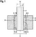
- Fig. 1shows a tool electrode and a workpiece 2 with a bore 3 in a schematic, partial sectional view for explaining a method for producing bores according to a first embodiment of the invention.
- the desired contour of a bore 4, in particular precision bore 4, which arises from the bore 3,has a diameter 5.
- the design of the bore 4 with the diameter 5is carried out by a plurality of method steps.
- the bore 4can serve as a high-precision guide bore with high dimensional and dimensional accuracy. Possible applications are injection technology or valve technology.
- the workpiece 2may in this case be a component or housing part of an injection valve or another component of an injection system.
- a plurality of holes 4can be configured in a workpiece 2. In the execution of the individual process steps, a parallel processing of several holes 3 of one or more workpieces 2 is possible.
- a bore 6 in the workpiece 2is produced in a conventional manner by a machining operation.
- the bore 6should have a cylindrical jacket-shaped ideal contour 8 with respect to a desired axis 7.
- the machiningis done under the influence of forces that produce the bore 6 with a real contour 6 in practice.
- This real contour 6has, for example, a projection 9, which results as a bulbous elevation between the real contour 6 and the ideal contour 8.
- a longitudinal axis of the bore 6may in this case also deviate from the desired axis 7.
- the bore 6is machined with an electrically abrading machining process.
- the tool electrode 1is introduced into the bore 6.
- a working gap (gap) 10there is a working gap (gap) 10.
- a diameter 11, the cylindrical tool electrode 1 in this embodimentis chosen so that no contact between the tool electrode 1 and the bore 6 exists.
- a working medium for the electrically-removing machining processis performed. This can also be done in a bathroom.
- the electrically removing machining processprocesses the bore 3 on the basis of the real contour 6 generated in the first step, wherein projections 9 are at least substantially removed. This results in the bore 3 with the shape correction 12.
- a mechanical processingcan be done by honing.
- the mechanical processingcan be performed precisely, so that the precision bore 4 results.
- the precision bore 4has a longitudinal axis which at least largely coincides with the desired axis 7.
- the diameter 5 of the precision bore 4is at least substantially constant.
- an at least largely cylindrical jacket-shaped configuration of the precision bore 4results.
- the precondition for the next method stepnamely the mechanical processing
- the electrically abrading machining methodin that a shape correction of the bore 3 with the real contour 6 takes place.
- the bore 3is then removed so far that it is designed with the shape correction 12.
- the desired dimensional accuracy and surface qualitycan be achieved, so that from the bore 3, the precision bore 4 is configured.
- the electrically-removing machining processwhich can be done thermally and anodically, the actual geometry of the bore 3, which has the real contour 6, to the desired geometry of the bore 3, which has the ideal contour 8, be aligned.
- a bore delay of the bore 3can be corrected.
- Thiscan also be a Delay can be corrected after a heat treatment.
- the subsequent mechanical processing with a mechanical machining tool, in particular a honing tool, such as a Honahlenot disturbed by projections 9, since they are removed.
- the combination of the electrically-removing machining method and the mechanical finishingis advantageous.
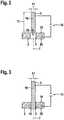
- Fig. 2shows the tool electrode 1 and the workpiece 2 in a schematic, partial sectional view for explaining the method for producing precision bores 4 according to a second embodiment of the invention.
- a voltage source 15is used.
- the tool electrode 1is connected to the cathode of the voltage source 15, while the workpiece 2 is connected to the anode of the voltage source 15.
- Via the voltage source 15, a voltageis applied between the tool electrode 1 and the workpiece 2, so that the electrically-removing machining process is set in motion.
- the longitudinal axis 16 of the tool electrode 1is coaxial with the target axis 7 of the bore 3 of the workpiece 2.
- a portion 17 of the tool electrode 1is shown in FIG the tool electrode 1 is cylindrical in shape.
- the section 17 of the tool electrode 1is initially located outside the bore 3 of the workpiece 2.
- the tool electrode 1is guided in a direction 18 along the desired axis 7 and the longitudinal axis 16 in the bore 3.
- the tool electrode 1can also be guided through the bore 6.
- the tool electrode 1is guided into the bore 3 from a side 19 of the workpiece 2, on which the tool electrode 1 is located in the initial state.
- another side 20 of the workpiece 2is shown, which faces away from the side 19.
- the portion 17 of the tool electrode 1partially emerges from the bore 3 at the side 20.
- the tool electrode 1can be guided with a constant advance into or through the bore 3. The method can also be carried out with distance control.
- the tool electrode 1can rotate relative to the workpiece 2 with respect to the longitudinal axis 16 in the implementation of the method.
- the tool electrode 1 and / or the workpiece 2can rotate about the desired axis 7. If both the tool electrode 1 and the workpiece 2 rotate, then both a synchronous and a mating run are possible. It is also possible that the tool electrode 1 rotates about the desired axis 7, while the workpiece 2 does not rotate. Further, it is possible that the workpiece 2 rotates about the target axis 7 while the tool electrode 1 is not rotating.
- the relative movement of the tool electrode 1 to the workpiece 2 along the longitudinal axis 16 by moving the tool electrode 1 and / or by moving the workpiece 2done.
- the supply of the working mediumcan be done from the side 19 in the bore 3, from the side 20 in the bore 3 or in the bathroom. Furthermore, the working medium can also be supplied through the tool electrode 1.
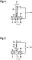
- Fig. 3shows the tool electrode 1 and the workpiece 2 in a schematic, partial sectional view for explaining the method for producing precision bores 4 according to a third embodiment of the invention.
- the tool electrode 1is relative to the workpiece 2 when the voltage generated by the voltage source 15 is applied between the tool electrode and the workpiece 2.
- the longitudinal axis 16 of the cylindrical tool electrode 1is coaxial with the target axis 7 of the bore 3.
- the tool electrode 1is guided through the bore 3 and protrudes on the side 20 of the bore 3.
- the diameter 11 of the tool electrode 1is in this case as large as possible chosen without the tool electrode 1, the pre-machined hole 3, the projections 9 may have touched.
- the tool electrode 1is not moved.
- the tool electrode 1to be set in oscillation along its longitudinal axis 16 during the electrical removal, for example by ultrasound.
- further variationsare possible, for example rotations of the tool electrode 1 relative to the workpiece 2 about the desired axis 7.
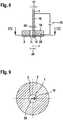
- Fig. 4shows the tool electrode 1 and the workpiece 2 in a schematic, partial sectional view for explaining the method for producing precision bores 4 according to a fourth embodiment of the invention.
- the longitudinal axis 16 of the cylindrical tool electrode 1is in this case coaxial with the desired axis 7 of the bore 3.
- the tool electrode 1immersed in the pre-machined hole 3 a.
- the tool electrode 1is through the bore 3 guided, wherein the tool electrode 1 protrudes on the side 20 of the bore 3.
- the diameter 11 of the tool electrode 1is selected as large as possible without the tool electrode 1 touching the workpiece 2.
- the tool electrode 1is guided out of the bore 3 of the workpiece 2 along its longitudinal axis 16 or along the desired axis 7.
- the tool electrode 1is moved in a direction 21.
- the movementcan be done with a constant feed.
- the movementcan also be distance-controlled.
- suitable variations of the methodare possible.
- the tool electrode 1can rotate relative to the tool 2 with respect to the desired axis 7.
- Fig. 5shows the tool electrode 1 and the workpiece 2 in a schematic, partial sectional view for explaining the method for producing precision bores 4 according to a fifth embodiment of the invention.
- the tool electrode 1is arranged with its longitudinal axis 16 coaxially on the desired axis 7.
- the tool electrode 1is designed as an arrow electrode 1.
- the arrow electrode 1has a head 25, which is configured conically at least in sections.
- the tool electrode 1is guided with the head 25 in front of the side 19 in the bore 3.
- the tool electrode 1is moved in the direction 18 when the voltage of the power source 15 is applied between the tool electrode 1 and the workpiece 2.
- process-related conicitiescan be avoided in the electrically abrading machining process.
- the machiningcan be done with constant feed. This is especially true for the ECM procedure. In an ECDM method, a constant feed or a distance control can take place.
- Fig. 6shows the tool electrode 1 and the workpiece 2 in a schematic, partial sectional view for explaining the method for producing precision bores 4 according to a sixth embodiment.
- the tool electrode 1is guided through the bore 3, the tool electrode 1 protruding from the bore 3 on the side 20.
- the diameter 11 of the tool electrode 1is chosen to be significantly smaller than a diameter 26 of the at least approximately cylindrical bore 3.
- the longitudinal axis 16 of the tool electrode 1is oriented parallel to the desired axis 7.
- the longitudinal axis 16is offset from the desired axis 7.
- the longitudinal axis 16 of the tool electrode 1is radially offset from the desired axis 7 of the bore 3.
- a gap 10is formed, which serves as a working gap 10.
- the tool electrode 1is moved about the target axis 7 in accordance with a circular motion 27.
- the diameter 11is chosen as large as possible without the tool electrode 1 touching the workpiece 2.
- the offset between the longitudinal axis 16 and the desired axis 7is selected to be as large as possible without a contact between the tool electrode 1 and the workpiece 2 during the circular movement 27.
- a constant circular motion 27can take place.
- the movementcan take place with constant circular motion 27 or distance-controlled. It is also possible that the circular movement 27 is performed several times, the tool electrode 1 after a selectable number of passes or continuously radially further away from the target axis 7 of the bore 3 away.
- the execution of the methodoffers several variations. No additional rotation can be provided between the tool electrode 1 and the workpiece 2. It is also possible that the tool electrode 1 rotates about its longitudinal axis 16 during the circular movement 27, while the workpiece 2 rotates about the desired axis 7. Synchronism and reverse are possible here. It is also possible that the tool electrode 1 rotates about its longitudinal axis 16, while the workpiece 2 does not rotate. The workpiece 2 can also rotate about the desired axis 7, while the tool electrode 1 has no additional rotation. The different rotations can be done in synchronism and countercurrent to the circular movement 27 of the tool electrode 1.
- Fig. 7shows a section through the in Fig. 6 illustrated tool electrode 1 and the workpiece 2 along the designated VII line of intersection to explain the method according to the sixth embodiment.
- the circular motion 27 of the tool electrode 1is illustrated.
- movements 28, 29, 30 of the tool electrode 1can be performed.
- Fig. 8shows the tool electrode 1 and the workpiece 2 in a schematic, partial sectional view for explaining the method for producing precision bores 4 according to a seventh embodiment.
- the diameter 11 of the tool electrode 1is in this case made smaller than the diameter 26 of the approximately cylindrical bore 3.
- the tool electrode 1is moved translationally in a direction of movement 30.
- the direction of movement 30can vary here.
- the workpiece 2rotates about the desired axis 7.
- the longitudinal axis 16 of the tool electrode 1is radially offset from the desired axis 7.
- Die Tool electrode 1protrudes through the bore 3.
- the diameter 11 of the tool electrode 1is again chosen so large that no contact with the workpiece 2 occurs.
- the tool electrode 1can be moved radially further in the direction of movement 30 away from the desired axis 7 of the bore 3. It is also possible that no further movement takes place during the process by setting the necessary working gap 10 correctly already at the beginning of the process.
- a constant feedoccurs.
- the EDM process or ECDM processcan be done with constant feed or distance controlled processing.
- electrically working machining method of the third embodimentis particularly suitable in one embodiment as EDM method, ECM method or ECDM method.
- electrically working machining method of the fourth embodimentis preferably carried out as EDM method or ECDM method.
- That on the basis of Fig. 5 described electrically working machining method of the fifth embodimentis preferably carried out as an ECM method or ECDM method.
- That on the basis of 6 and 7 described electrically working machining method of the seventh embodimentis particularly suitable as EDM method, ECM method or ECDM method.
- That on the basis of 8 and 9 described electrically working machining method of the seventh embodimentis particularly suitable in one embodiment as EDM method, ECM method or ECDM method.
- the electrically abrading machining processis preferably followed directly by a mechanical processing in order to process the machined with the electrically machining process hole 3, wherein the projections 9 are at least substantially removed, the finishing of the precision bore 4.
- This mechanical processingis preferably carried out by honing.
Landscapes
- Engineering & Computer Science (AREA)
- Mechanical Engineering (AREA)
- Physics & Mathematics (AREA)
- Geometry (AREA)
- Manufacturing & Machinery (AREA)
- Chemical & Material Sciences (AREA)
- Combustion & Propulsion (AREA)
- General Engineering & Computer Science (AREA)
- Thermal Sciences (AREA)
- Electrical Discharge Machining, Electrochemical Machining, And Combined Machining (AREA)
- Finish Polishing, Edge Sharpening, And Grinding By Specific Grinding Devices (AREA)
Description
Translated fromGermanDie Erfindung betrifft ein Verfahren zum Herstellen von Bohrungen, insbesondere von Präzisionsbohrungen. Speziell betrifft die Erfindung die Herstellung von hochpräzisen Führungsbohrungen mit hoher Maß- und Formgenauigkeit, die beispielsweise in der Einspritztechnik, insbesondere bei Brennstoffeinspritzventilen, und der Ventiltechnik zum Einsatz kommen können.The invention relates to a method for producing bores, in particular precision bores. Specifically, the invention relates to the production of high-precision guide holes with high dimensional and dimensional accuracy, which can be used, for example, in injection technology, in particular in fuel injection valves, and the valve technology.
Die Herstellung von hochpräzisen Führungsbohrungen erfolgt im letzten Bearbeitungsschritt durch mechanische Bearbeitungsverfahren, wie zum Beispiel Schleifen oder Honen. Durch die vorausgegangenen Bearbeitungsschritte, insbesondere durch Weichbearbeitungen, wie beispielsweise Bohren, oder eine Wärmebehandlung, weisen die Führungsbohrungen zu diesem Zeitpunkt in der Regel eine erhebliche Abweichung vom Endmaß und der Endform auf. Durch den letzten mechanischen Bearbeitungsschritt, das heißt durch das Schleifen oder Honen, sollen diese Abweichungen idealerweise korrigiert werden. Auf Grund von verfahrensbedingten Nachteilen, wie beispielsweise Prozesskräften, die zu einer Ausrichtung der Werkzeuge führen, ist eine Formkorrektur nur im eingeschränkten Maße und gegebenenfalls nur durch eine mechanische Bearbeitung mit geringen Materialabtragungsraten zur Reduzierung der verfahrensbedingten Nachteile möglich. Dies betrifft speziell Bohrungen mit sehr kleinen Durchmessern, beispielsweise von weniger als zwei Millimeter. Falls das gewünschte Ergebnis durch die mechanische Bearbeitung mit geringer Materialabtragsrate möglich ist, dann führt auch dies zu hohen Prozesszeiten und damit zu hohen Herstellungskosten.The production of high-precision guide bores takes place in the last processing step by mechanical processing methods, such as grinding or honing. By the preceding processing steps, in particular by soft machining, such as drilling, or a heat treatment, the guide holes at this time usually a considerable deviation from the final gauge and the final shape. By the last mechanical processing step, ie by grinding or honing, these deviations should ideally be corrected. Due to process-related disadvantages, such as process forces that lead to an alignment of the tools, a shape correction is possible only to a limited extent and possibly only by a mechanical machining with low material removal rates to reduce the process-related disadvantages. This concerns especially holes with very small diameters, for example, less than two millimeters. If the desired result is possible by the mechanical processing with a low material removal rate, then this also leads to high process times and thus to high production costs.
Aus der
Das erfindungsgemäße Verfahren zum Herstellen von Bohrungen mit den Merkmalen des Anspruchs 1 hat den Vorteil, dass der Herstellungsprozess optimiert ist. Speziell ist eine hochpräzise und qualitativ hochwertige Herstellung von Bohrungen möglich, wobei auch bei geringen Durchmessern eine wirtschaftliche Herstellung möglich ist.The inventive method for producing bores with the features of
Durch die in den Unteransprüchen aufgeführten Maßnahmen sind vorteilhafte Weiterbildungen des im Anspruch 1 angegebenen Verfahrens möglich.The measures listed in the dependent claims advantageous developments of the method specified in
In vorteilhafter Weise besteht die Prozessfolge aus dem elektrisch abtragenden Bearbeitungsverfahren und der nachgeordneten mechanischen Honbearbeitung. Durch das elektrisch abtragende Bearbeitungsverfahren erfolgt hierbei gezielt eine kraftfreie Formkorrektur. Durch die nachgeordnete mechanische Honbearbeitung kann die Ausgestaltung des exakten Maßes und der gewünschten Oberflächenqualität der Bohrung erfolgen. Durch die gezielte Verfahrensabfolge und durch die aufeinander abgestimmten Bearbeitungsprozesse können Bohrungen, insbesondere Führungsbohrungen, hinsichtlich der Maßgenauigkeit und der Formgenauigkeit deutlich verbessert gefertigt werden.The process sequence advantageously consists of the electrically removing machining process and the downstream mechanical honing treatment. Due to the electrically abrasive machining process, a force-free one is used Shape correction. By subordinate mechanical Honbearbeitung the configuration of the exact size and the desired surface quality of the bore can be done. Through the targeted process sequence and through the coordinated machining processes bores, in particular guide holes, can be made significantly improved in terms of dimensional accuracy and dimensional accuracy.
Außerdem ist besonders bei Bohrungen mit kleinen Durchmessern, insbesondere mit Durchmessern von weniger als 2 mm, eine Reduzierung der Gesamtbearbeitungszeit möglich.In addition, especially with holes with small diameters, in particular with diameters of less than 2 mm, a reduction of the total machining time is possible.
In vorteilhafter Weise ist als elektrisch abtragendes Bearbeitungsverfahren ein ECM Verfahren, ein EDM-Verfahren oder ein ECDM-Verfahren gewählt. ECM bedeutet elektrochemisches Abtragen (Elysieren). EDM bedeutet elektro-erosives Abtragen (Funkenerosion). ECDM bedeutet elektrochemisch-erosives Abtragen.Advantageously, an ECM method, an EDM method or an ECDM method is selected as the electrically removing machining method. ECM means electrochemical removal (Elysieren). EDM means electro-erosive removal (spark erosion). ECDM means electrochemical erosive ablation.
In vorteilhafter Weise ist eine Trennung des Bearbeitungsschwerpunkts, der Formkorrektur und des Bearbeitungsschwerpunkts der Endmaß- und Oberflächenqualität bei der Endbearbeitung von Bohrungen durch die gezielte Nutzung von einzelnen Verfahrensvorteilen bezogen auf den jeweiligen Bearbeitungsschwerpunkt möglich. Dabei ist eine Formkorrektur durch das elektrisch abtragende Bearbeitungsverfahren kraftfrei und somit hochpräzise möglich. Anschließend werden das Endmaß und die Oberflächenqualität durch den mechanischen Bearbeitungsprozess, beispielsweise Honen, hochpräzise und qualitativ hochwertig hergestellt.Advantageously, a separation of the processing center, the shape correction and the processing focus of the final dimension and surface quality in the completion of drilling through the targeted use of individual process advantages based on the respective processing focus is possible. In this case, a shape correction by the electrically-removing machining process without force and thus highly accurate possible. Subsequently, the final dimension and the surface quality are produced by the mechanical machining process, for example honing, with high precision and high quality.
Durch diese Abfolge und durch die gezielte Nutzung von einzelnen Verfahrensvorteilen bezogen auf den jeweiligen Bearbeitungsschwerpunkt ist eine Steigerung der Bearbeitungsgenauigkeit und eine Reduzierung der Gesamtbearbeitungszeit bei der Endbearbeitung von Bohrungen, insbesondere Führungsbohrungen, möglich. Speziell betrifft dies Bohrungen mit kleinen Durchmessern, die kleiner als 2 mm sein können.Through this sequence and through the targeted use of individual process advantages relative to the respective main focus of the process, it is possible to increase the machining accuracy and to reduce the overall processing time in the final machining of bores, in particular guide bores. Specifically, this relates to holes with small diameters, which may be smaller than 2 mm.
Das mechanische Bearbeiten der mit dem elektrisch abtragenden Bearbeitungsverfahren bearbeiteten Bohrung erfolgt somit in vorteilhafter Weise durch Honen der mit dem elektrisch abtragenden Bearbeitungsverfahren bearbeiteten Bohrung. Durch die Bearbeitung der Bohrung mit dem elektrisch abtragenden Bearbeitungsverfahren erfolgt eine Formkorrektur, bei der innerhalb einer vorgegebenen Idealkontur liegende Vorsprünge der Kontur der Bohrung durch elektrisches Abtragen zumindest im Wesentlichen entfernt werden. Innerhalb der vorgegebenen Idealkontur liegende Vorsprünge würden bei der nachfolgenden mechanischen Bearbeitung Kräfte auf das Werkzeug, insbesondere eine Honahle, ausüben. Hierdurch kann es beispielsweise zu einer Verbiegung der Honahle kommen, was sich in einer Formungenauigkeit und Beeinträchtigung der Oberflächengüte auswirkt. Durch die Abtragung der Vorsprünge, die innerhalb der vorgegebenen Idealkontur liegen, werden beispielsweise solche unerwünschten, auf das Werkzeug zur mechanischen Bearbeitung wirkenden Kräfte zumindest verringert. Hierdurch können die gewünschte Formgenauigkeit und Oberflächengüte durch die mechanische Bearbeitung erzielt werden. Das Bearbeiten der Bohrung mit dem elektrisch abtragenden Bearbeitungsverfahren erfolgt mittels einer Werkzeugelektrode und eine Längsachse der Werkzeugelektrode wird bei der Bearbeitung der Bohrung zumindest näherungsweise parallel zu einer Sollachse der Bohrung orientiert. Da das elektrisch abtragende Bearbeitungsverfahren eine kraftfreie Formkorrektur ermöglicht, kann innerhalb gewisser Grenzen eine beliebige Wahl der Längsachse der Werkzeugelektrode bezüglich der Bohrung erfolgen. Die Werkzeugelektrode wird mit geeigneten Abmessungen, insbesondere einem geeigneten Durchmesser, gewählt, so dass beim Ausrichten der Werkzeugelektrode an der Sollachse der Bohrung keine Berührung mit dem Werkstück, in dem die Bohrung ausgestaltet ist, das heißt der Bohrungswand, erfolgt. Da die Intensität des elektrischen Abtragens von der lokalen Spaltbreite zwischen der Werkzeugelektrode und dem Werkstück abhängt, ergibt sich durch die Ausrichtung der Längsachse der Werkzeugelektrode an der Sollachse der Bohrung eine Vergleichmäßigung der Bohrung entlang der Längsachse der Werkzeugelektrode. Der Begriff der parallelen Orientierung der Längsachse der Werkzeugelektrode zu der Sollachse der Bohrung schließt hierbei eine koaxiale Orientierung ein, bei der die Längsachse der Werkzeugelektrode und die Sollachse der Bohrung aufeinander liegen und somit identisch sind.The machining of the hole machined with the electrically-removing machining method is thus advantageously carried out by honing the hole machined with the electrically-removing machining method. By machining the bore with the electrically-removing machining process, a shape correction takes place in which protrusions of the contour of the bore lying within a predetermined ideal contour are at least substantially removed by electrical removal. Within the given ideal contour lying projections would exercise in the subsequent mechanical processing forces on the tool, in particular a Honahle. This can lead, for example, to a bending of the honing haw, which results in an inaccurate shape and impairment of the surface quality. By removing the projections, which are within the predetermined ideal contour, for example, such unwanted, acting on the tool for mechanical processing forces are at least reduced. As a result, the desired dimensional accuracy and surface quality can be achieved by the mechanical processing. The machining of the bore with the electrically removing machining process takes place by means of a tool electrode and a longitudinal axis of the tool electrode is oriented at least approximately parallel to a desired axis of the bore during machining of the bore. Since the electrically abrading machining method allows a force-free shape correction, can be done within certain limits, any choice of the longitudinal axis of the tool electrode with respect to the bore. The tool electrode is selected with suitable dimensions, in particular a suitable diameter, so that when aligning the tool electrode at the desired axis of the bore no contact with the workpiece in which the bore is configured, that is, the bore wall, takes place. Since the intensity of the electrical removal depends on the local gap width between the tool electrode and the workpiece, the orientation of the longitudinal axis of the tool electrode at the nominal axis of the bore results in a homogenization of the bore along the longitudinal axis of the tool electrode. The term parallel orientation of the longitudinal axis of the tool electrode to the desired axis of the bore in this case includes a coaxial orientation, in which the longitudinal axis of the tool electrode and the desired axis of the bore lie on each other and are therefore identical.
Vorteilhaft ist es, dass die Längsachse der Werkzeugelektrode bei der Bearbeitung der Bohrung zumindest zeitweise auf der Sollachse der Bohrung liegt. Speziell bei dieser Anordnung der Werkzeugelektrode ist es vorteilhaft, dass die Werkzeugelektrode bei der Bearbeitung der Bohrung zumindest zeitweise entlang ihrer Längsachse in die Bohrung hineingeführt wird und/oder dass die Werkzeugelektrode bei der Bearbeitung der Bohrung zumindest zeitweise entlang ihrer Längsachse aus der Bohrung herausgeführt wird und/oder dass die Werkzeugelektrode bei der Bearbeitung der Bohrung zumindest zeitweise durch die Bohrung hindurchgeführt ist und in zumindest einer Richtung entlang ihrer Längsachse relativ zu der Bohrung verfahren wird. Hierbei ist es möglich, dass die Werkzeugelektrode bei der Bearbeitung der Bohrung auf einer festen Längsachse angeordnet bleibt, wobei ein Vorschub der Werkzeugelektrode entlang der Längsachse erfolgt. Die Zuführung des Arbeitsmediums kann hierbei von einer Seite erfolgen, von der auch die Werkzeugelektrode zugeführt wird, oder von der anderen Seite. Die Zuführung des Arbeitsmediums kann auch im Bad erfolgen. Durch die Bewegung der Werkzeugselektrode kann das elektrochemische Abtragen zur Formkorrektur vorteilhaft beeinflusst werden.It is advantageous that the longitudinal axis of the tool electrode during machining of the bore is at least temporarily on the desired axis of the bore. Especially with this arrangement of the tool electrode, it is advantageous that the tool electrode in the Machining the bore is guided at least temporarily along its longitudinal axis in the bore and / or that the tool electrode during machining of the bore is led out at least temporarily along its longitudinal axis from the bore and / or that the tool electrode during machining of the bore at least temporarily through the bore is passed and is moved in at least one direction along its longitudinal axis relative to the bore. In this case, it is possible for the tool electrode to remain arranged on a fixed longitudinal axis during the machining of the bore, wherein a feed of the tool electrode takes place along the longitudinal axis. The supply of the working medium can in this case take place from one side, from which the tool electrode is also supplied, or from the other side. The supply of the working medium can also be done in the bathroom. The movement of the tool electrode can advantageously influence the electrochemical removal for shape correction.
Vorteilhaft ist es auch, dass die Werkzeugelektrode bei der Bearbeitung der Bohrung relativ zu der Bohrung zumindest näherungsweise ruht. Hierbei ist es ferner vorteilhaft, dass die Werkzeugselektrode bei der Bearbeitung der Bohrung mit einer oszillierenden Bewegung entlang der Sollachse betätigt wird. Die oszillierende Bewegung kann beispielsweise durch Ultraschall erzeugt werden. Hierdurch ist ohne ein Verfahren der Werkzeugelektrode ein vorteilhafte Beeinflussung des elektrischen Abtragens möglich.It is also advantageous that the tool electrode at least approximately rests relative to the bore during machining of the bore. Here, it is also advantageous that the tool electrode is actuated during the machining of the bore with an oscillating movement along the desired axis. The oscillating movement can be generated for example by ultrasound. As a result, without a method of the tool electrode, an advantageous influencing of the electrical removal is possible.
Vorteilhaft ist es auch, dass die Werkzeugelektrode bei der Bearbeitung der Bohrung mit einer Kreisbewegung um die Sollachse der Bohrung bewegt wird. Zusätzlich oder alternativ ist es von Vorteil, dass die Werkzeugelektrode bei der Bearbeitung der Bohrung zumindest zeitweise in und/oder entgegen einer radialen Richtung senkrecht zu der Sollachse bewegt wird. Hierdurch kann das elektrochemische Abtragen mehr oder weniger lokalisiert werden, um in Bezug auf den jeweiligen Anwendungsfall eine Vergleichsmäßigung der Bohrung in Bezug auf die Sollachse zu erzielen.It is also advantageous that the tool electrode is moved during the machining of the bore with a circular movement about the desired axis of the bore. Additionally or alternatively, it is advantageous that the tool electrode is moved during machining of the bore at least temporarily in and / or against a radial direction perpendicular to the desired axis. As a result, the electrochemical removal can be more or less localized to achieve a comparison of the bore with respect to the desired axis with respect to the particular application.
Vorteilhaft ist es auch, dass die Werkzeugelektrode als Pfeilelektrode ausgestaltet ist. Hierdurch kann das elektrochemische Abtragen im Zeitverlauf lokal bezüglich der Längsachse der Werkzeugelektrode erfolgen.It is also advantageous that the tool electrode is designed as an arrow electrode. As a result, the electrochemical removal over time can be carried out locally with respect to the longitudinal axis of the tool electrode.
Vorteilhaft ist es auch, dass zumindest ein Bearbeitungsabschnitt der Werkzeugelektrode, der bei der Bearbeitung in die Bohrung geführt wird, als zylinderförmiger Bearbeitungsabschnitt ausgestaltet ist und dass ein Durchmesser des zylinderförmigen Bearbeitungsabschnitts so groß ausgewählt wird, dass sich der Bearbeitungsabschnitt der Werkzeugselektrode berührungslos in die Bohrung einführen lässt. Hierbei kann der Durchmesser des zylinderförmigen Bearbeitungsabschnitts speziell möglichst groß gewählt sein. Durch diese Ausgestaltung kann entlang der Sollachse eine Vergleichmäßigung erfolgen, während entsprechend dem gewählten Durchmesser durch paralleles, aber nicht koaxiales Ausrichten der Längsachse der Werkzeugelektrode eine radial selektive Abtragung möglich ist. Durch Bewegen der Werkzeugselektrode entlang einer Kreisbahn kann hierbei eine Vergleichmäßigung der Bohrung in Bezug auf die Sollachse erzielt werden. Auch andere Bewegungen der Werkzeugelektrode sind möglich.It is also advantageous that at least one machining section of the tool electrode, which is guided during machining into the bore, is designed as a cylindrical machining section and that a diameter of the cylindrical machining section is selected so large that the machining section of the tool electrode is inserted without contact into the bore leaves. In this case, the diameter of the cylindrical processing section can be selected as large as possible be. As a result of this embodiment, a homogenization can take place along the setpoint axis, while according to the selected diameter a radially selective removal is possible by aligning the longitudinal axis of the tool electrode in parallel but not coaxially. By moving the tool electrode along a circular path in this case a homogenization of the bore can be achieved with respect to the desired axis. Other movements of the tool electrode are possible.
Bevorzugte Ausführungsbeispiele der Erfindung sind in der nachfolgenden Beschreibung unter Bezugnahme auf die beigefügten Zeichnungen, in denen sich entsprechende Elemente mit übereinstimmenden Bezugszeichen versehen sind, näher erläutert. Es zeigt:
Fig. 1 eine Werkzeugelektrode und ein Werkstück in einer schematischen, auszugsweisen Schnittdarstellung zur Erläuterung eines Verfahrens zum Herstellen von Bohrungen entsprechend einer ersten Ausführungsform der Erfindung;Fig. 2 eine Werkzeugselektrode und ein Werkstück in einer schematischen, auszugsweisen Schnittdarstellung zur Erläuterung eines Verfahrens zum Herstellen von Bohrungen entsprechend einer zweiten Ausführungsform der Erfindung;Fig. 3 eine Werkzeugselektrode und ein Werkstück in einer schematischen, auszugsweisen Schnittdarstellung zur Erläuterung eines Verfahrens zum Herstellen von Bohrungen entsprechend einer dritten Ausführungsform der Erfindung;Fig. 4 eine Werkzeugselektrode und ein Werkstück in einer schematischen, auszugsweisen Schnittdarstellung zur Erläuterung eines Verfahrens zum Herstellen von Bohrungen entsprechend einer vierten Ausführungsform der Erfindung;Fig. 5 eine Werkzeugselektrode und ein Werkstück in einer schematischen, auszugsweisen Schnittdarstellung zur Erläuterung eines Verfahrens zum Herstellen von Bohrungen entsprechend einer fünften Ausführungsform der Erfindung;Fig. 6 eine Werkzeugselektrode und ein Werkstück in einer schematischen, auszugsweisen Schnittdarstellung zur Erläuterung eines Verfahrens zum Herstellen von Bohrungen entsprechend einer sechsten Ausführungsform der Erfindung;Fig. 7 einen Schnitt durch die inFig. 6 dargestellte Werkzeugelektrode und das Werkstück entlang der mit VII bezeichneten Schnittlinie zur Erläuterung des Verfahrens entsprechend der sechsten Ausführungsform;Fig. 8 eine Werkzeugelektrode und ein Werkstück in einer schematischen, auszugsweisen Schnittdarstellung zur Erläuterung eines Verfahrens zum Herstellen von Bohrungen entsprechend einer siebten Ausführungsform der Erfindung undFig. 9 einen Schnitt durch die inFig. 8 dargestellte Werkzeugelektrode und das Werkstück entlang der mit IX bezeichneten Schnittlinie zur Erläuterung des Verfahrens entsprechend der siebten Ausführungsform.
Fig. 1 a tool electrode and a workpiece in a schematic, partial sectional view for explaining a method for producing bores according to a first embodiment of the invention;Fig. 2 a tool electrode and a workpiece in a schematic, partial sectional view for explaining a method for producing bores according to a second embodiment of the invention;Fig. 3 a tool electrode and a workpiece in a schematic, partial sectional view for explaining a method for producing bores according to a third embodiment of the invention;Fig. 4 a tool electrode and a workpiece in a schematic, partial sectional view for explaining a method for producing bores according to a fourth embodiment of the invention;Fig. 5 a tool electrode and a workpiece in a schematic, partial sectional view for explaining a method for producing bores according to a fifth embodiment of the invention;Fig. 6 a tool electrode and a workpiece in a schematic, partial sectional view for explaining a method for producing bores according to a sixth embodiment of the invention;Fig. 7 a section through the inFig. 6 shown tool electrode and the workpiece along the designated VII line of intersection to explain the method according to the sixth embodiment;Fig. 8 a tool electrode and a workpiece in a schematic, partial sectional view for explaining a method for producing bores according to a seventh embodiment of the invention andFig. 9 a section through the inFig. 8 illustrated tool electrode and the workpiece along the section line designated IX to explain the method according to the seventh embodiment.
In einem ersten Verfahrensschritt wird auf herkömmliche Weise eine Bohrung 6 in dem Werkstück 2 durch eine spanabhebende Bearbeitung erzeugt. Idealerweise sollte die Bohrung 6 bezüglich einer Sollachse 7 eine zylindermantelförmige Idealkontur 8 aufweisen. Die zerspanende Bearbeitung erfolgt jedoch unter dem Einfluss von Kräften, die in der Praxis die Bohrung 6 mit einer Realkontur 6 erzeugen. Diese Realkontur 6 weist beispielsweise einen Vorsprung 9 auf, der sich als bauchförmige Erhebung zwischen der Realkontur 6 und der Idealkontur 8 ergibt. Eine Längsachse der Bohrung 6 kann hierbei auch von der Sollachse 7 abweichen.In a first method step, a
Nach der zerspanenden Bearbeitung des Werkstücks 2 wird die Bohrung 6 mit einem elektrisch abtragenden Bearbeitungsverfahren bearbeitet. Hierfür wird die Werkzeugelektrode 1 in die Bohrung 6 eingebracht. Zwischen der Werkzeugelektrode 1 und der momentanen Bohrung 3, das heißt der Realkontur 6, besteht ein Arbeitsspalt (Spalt) 10. Ein Durchmesser 11, der in diesem Ausführungsbeispiel zylinderförmigen Werkzeugelektrode 1 ist hierbei so gewählt, dass kein Kontakt zwischen der Werkzeugelektrode 1 und der Bohrung 6 besteht.After the machining of the
Durch den Spalt 10 wird ein Arbeitsmedium für das elektrisch abtragende Bearbeitungsverfahren geführt. Dies kann auch in einem Bad erfolgen.Through the
Das elektrisch abtragende Bearbeitungsverfahren bearbeitet die Bohrung 3 ausgehend von der im ersten Schritt erzeugten Realkontur 6, wobei Vorsprünge 9 zumindest im Wesentlichen entfernt werden. Hierdurch ergibt sich die Bohrung 3 mit der Formkorrektur 12. Somit hat die Bohrung 3 nach dem elektrisch abtragenden Behandlungsverfahren die Ausgestaltung der dargestellten Bohrung (Formkorrektur) 12.The electrically removing machining process processes the
Da Vorsprünge 9 entfernt sind, kann ausgehend von der Bohrung 12 eine mechanische Bearbeitung der mit dem elektrisch abtragenden Bearbeitungsverfahren bearbeiteten Bohrung 3 erfolgen. Insbesondere kann eine mechanische Bearbeitung durch Honen erfolgen. Hierbei kann das mechanische Bearbeiten präzise durchgeführt werden, so dass sich die Präzisionsbohrung 4 ergibt. Die Präzisionsbohrung 4 weist eine Längsachse auf, die zumindest weitgehend mit der Sollachse 7 übereinstimmt. Außerdem ist der Durchmesser 5 der Präzisionsbohrung 4 zumindest weitgehend konstant. Ferner ergibt sich eine zumindest weitgehend zylindermantelförmige Ausgestaltung der Präzisionsbohrung 4.Since
Somit kann durch das elektrisch abtragende Bearbeitungsverfahren die Voraussetzung für den nächsten Verfahrensschritt, nämlich die mechanische Bearbeitung, geschaffen werden, indem eine Formkorrektur der Bohrung 3 mit der Realkontur 6 erfolgt. Durch das elektrisch abtragende Bearbeitungsverfahren wird die Bohrung 3 dann so weit abgetragen, dass diese mit der Formkorrektur 12 ausgestaltet ist. Durch die mechanische Endbearbeitung kann dann die gewünschte Formgenauigkeit und Oberflächengüte erzielt werden, so dass aus der Bohrung 3 die Präzisionsbohrung 4 ausgestaltet wird.Thus, the precondition for the next method step, namely the mechanical processing, can be created by the electrically abrading machining method, in that a shape correction of the
Durch das elektrisch abtragende Bearbeitungsverfahren, das thermisch und anodisch erfolgen kann, kann die Ist-Geometrie der Bohrung 3, die die Realkontur 6 aufweist, an die Soll-Geometrie der Bohrung 3, die die Idealkontur 8 aufweist, angeglichen werden. Speziell kann hierbei ein Bohrungsverzug der Bohrung 3 korrigiert werden. Hierbei kann auch ein Verzug nach einer Wärmebehandlung korrigiert werden. Somit wird die nachfolgende mechanische Bearbeitung mit einem mechanischen Bearbeitungswerkzeug, insbesondere einem Honwerkzeug, wie beispielsweise einer Honahle, durch Vorsprünge 9 nicht gestört, da diese entfernt sind. Insbesondere bei Mikrogeometrien und/oder unsymmetrisch konstruierten Werkstücken 2 beziehungsweise Bauteilen ist die Kombination aus dem elektrisch abtragenden Bearbeitungsverfahren und dem mechanischen Endbearbeiten von Vorteil.By the electrically-removing machining process, which can be done thermally and anodically, the actual geometry of the
Bei der Ausführung des elektrisch abtragenden Bearbeitungsverfahrens sind unterschiedliche Ausführungsformen möglich, die einzeln oder in Kombination ausgeführt werden können.In the embodiment of the electrically-removing machining method, different embodiments are possible, which can be carried out individually or in combination.
Die Werkzeugelektrode 1 kann bei der Durchführung des Verfahrens relativ zu dem Werkstück 2 bezüglich der Längsachse 16 rotieren. Hierbei können die Werkzeugelektrode 1 und/oder das Werkstück 2 um die Sollachse 7 rotieren. Wenn sowohl die Werkzeugelektrode 1 als auch das Werkstück 2 rotieren, dann sind sowohl ein Gleichlauf als auch ein Gegenlauf möglich. Möglich ist es auch, dass die Werkzeugelektrode 1 um die Sollachse 7 rotiert, während das Werkstück 2 nicht rotiert. Ferner ist es möglich, dass das Werkstück 2 um die Sollachse 7 rotiert, während die Werkzeugelektrode 1 nicht rotiert. Außerdem kann auch die Relativbewegung der Werkzeugelektrode 1 zu dem Werkstück 2 entlang der Längsachse 16 durch Bewegen der Werkzeugelektrode 1 und/oder durch Bewegen des Werkstücks 2 erfolgen.The
Die Zuführung des Arbeitsmediums kann von der Seite 19 aus in die Bohrung 3, von der Seite 20 aus in die Bohrung 3 oder auch im Bad erfolgen. Ferner kann das Arbeitsmedium auch durch die Werkzeugelektrode 1 zugeführt werden.The supply of the working medium can be done from the
Bei gegebenem Versatz der Längsachse 16 bezüglich der Sollachse 7 ist der Durchmesser 11 so groß wie möglich gewählt, ohne dass die Werkzeugelektrode 1 das Werkstück 2 berührt. Dies ist gleichbedeutend damit, dass bei gegebenem Durchmesser 11 der Werkzeugelektrode 1 der Versatz zwischen der Längsachse 16 und der Sollachse 7 möglichst groß gewählt wird, ohne dass während der Kreisbewegung 27 eine Berührung zwischen der Werkzeugelektrode 1 und dem Werkstück 2 erfolgt. Speziell beim ECM-Verfahren kann eine konstante Kreisbewegung 27 erfolgen. Beim EDM-Verfahren oder ECDM-Verfahren kann die Bewegung mit konstanter Kreisbewegung 27 oder abstandsgeregelt erfolgen. Möglich ist es auch, dass die Kreisbewegung 27 mehrfach durchgeführt wird, wobei die Werkzeugelektrode 1 nach einer wählbaren Anzahl von Durchläufen oder kontinuierlich radial weiter von der Sollachse 7 der Bohrung 3 weg verstellt wird.For a given offset of the
Die Ausführung des Verfahrens bietet hierbei mehrere Variationsmöglichkeiten. Zwischen der Werkzeugelektrode 1 und dem Werkstück 2 kann keine zusätzliche Rotation vorgesehen sein. Möglich ist es auch, dass die Werkzeugelektrode 1 während der Kreisbewegung 27 um ihre Längsachse 16 rotiert, während das Werkstück 2 um die Sollachse 7 rotiert. Gleichlauf und Gegenlauf sind hierbei möglich. Möglich ist es auch, dass die Werkzeugelektrode 1 um ihre Längsachse 16 rotiert, während das Werkstück 2 nicht rotiert. Das Werkstück 2 kann auch um die Sollachse 7 rotieren, während die Werkzeugelektrode 1 keine zusätzliche Rotation hat. Die unterschiedlichen Rotationen können hierbei im Gleichlauf und Gegenlauf zur Kreisbewegung 27 der Werkzeugelektrode 1 erfolgen.The execution of the method offers several variations. No additional rotation can be provided between the
Während des Verfahrens kann die Werkzeugelektrode 1 radial in der Bewegungsrichtung 30 weiter von der Sollachse 7 der Bohrung 3 weg bewegt werden. Möglich ist es auch, dass keine weitere Bewegung während des Verfahrens erfolgt, indem bereits bei Prozessbeginn der notwendige Arbeitsspalt 10 richtig eingestellt wird. Speziell beim ECM-Verfahren erfolgt ein konstanter Vorschub. Speziell beim EDM-Verfahren oder ECDM-Verfahren kann mit konstantem Vorschub oder abstandsgeregelt eine Bearbeitung erfolgen.During the process, the
Die beschriebenen Ausführungsformen können einzeln oder auch in beliebigen Kombinationen zur Bearbeitung des Werkstücks 2 kombiniert werden, um die Präzisionsbohrung 4 auszubilden.The described embodiments can be combined individually or in any combination for machining the
Das anhand der
Das anhand der
Das anhand der
Das anhand der
Das anhand der
Das anhand der
Nach dem elektrisch abtragenden Bearbeitungsverfahren schließt sich vorzugsweise direkt eine mechanische Bearbeitung an, um die mit dem elektrisch abtragenden Bearbeitungsverfahren bearbeitete Bohrung 3, bei der Vorsprünge 9 zumindest im Wesentlichen entfernt sind, der Endbearbeitung zur Präzisionsbohrung 4 zu unterziehen. Dieses mechanische Bearbeiten erfolgt vorzugsweise durch Honen.After the electrically abrading machining process is preferably followed directly by a mechanical processing in order to process the machined with the electrically
Die Erfindung ist nicht auf die beschriebenen Ausführungsbeispiele beschränkt.The invention is not limited to the described embodiments.
Claims (9)
- Method for producing highly precise guide bores (4) with a predefined ideal contour (8) and a nominal axis (7), which has the following machining steps:producing a bore (3) in a workpiece (2) by machining, wherein the bore (3) comprises an actual contour (6) with at least one protrusion (9) within the predefined ideal contour (8), and a longitudinal axis which deviates from the nominal axis (7),machining the bore (3) by an electrical discharge machining method, wherein the at least one protrusion (9), located within the predefined ideal contour (8) of the contour of the bore (3), is at least substantially removed by electrical discharge machining and an actual geometry of the bore (3), which has the actual contour (6), is matched to a nominal geometry of the bore (3), which has the ideal contour (8),and subsequently, mechanical machining of the bore (3) machined by the electrical discharge machining method, wherein the highly precise guide bore (4) is produced, the longitudinal axis of which coincides at least largely with the nominal axis (7).
- Method according to Claim 1,
characterized
in that the machining of the bore (3) by the electrical discharge machining method takes place by means of a tool electrode (1), and in that a longitudinal axis (16) of the tool electrode (1) is oriented at least approximately parallel to a nominal axis (7) of the bore (3) during the machining of the bore (3). - Method according to Claim 2,
characterized
in that the longitudinal axis (16) of the tool electrode (1) at least temporarily lies at least approximately on the nominal axis (7) of the bore (3) during the machining of the bore (3). - Method according to Claim 2 or 3,
characterized
in that the tool electrode (1) is guided at least temporarily into the bore (3) along its longitudinal axis (16) during the machining of the bore (3), and/or in that the tool electrode (1) is guided at least temporarily out of the bore (3) along its longitudinal axis (16) during the machining of the bore (3), and/or
in that the tool electrode (1) is guided at least temporarily through the bore (3) during the machining of the bore (3) and is moved in at least one direction (18, 21) along its longitudinal axis (16) relative to the bore (3). - Method according to one of Claims 2 to 4,
characterized
in that the tool electrode (1) at least temporarily rests at least approximately relative to the bore (3) during the machining of the bore (3). - Method according to Claim 5,
characterized
in that the tool electrode (1) is activated so as to carry out an oscillating movement along the nominal axis (7) during the machining of the bore (3). - Method according to one of Claims 2 to 6,
characterized
in that the tool electrode (1) is moved at least temporarily with a circular movement (27) about the nominal axis (7) of the bore (3) during the machining of the bore (3), and/or
in that the tool electrode (1) is moved at least temporarily in and/or counter to a direction (28, 29, 30) perpendicular to the nominal axis (7) during the machining of the bore (3). - Method according to one of Claims 2 to 7,
characterized
in that, during the electrical discharge machining method, the tool electrode (1) rotates about its longitudinal axis (16) and/or the workpiece (2) rotates about the nominal axis (7). - Method according to one of Claims 2 to 7,
characterized
in that the tool electrode (1) is configured as an arrow electrode (1), or in that at least one machining portion (17) of the tool electrode (1), said machining portion (17) being guided into the bore (3) during machining, is configured as a cylindrical machining portion (17), and in that a diameter (11) of the cylindrical machining portion (17) is selected to be large enough that the machining portion (17) of the tool electrode (1) can be introduced into the bore (1) in a contactless manner or can be guided in the bore (3) in a contactless manner.
Applications Claiming Priority (2)
| Application Number | Priority Date | Filing Date | Title |
|---|---|---|---|
| DE102010063721 | 2010-12-21 | ||
| DE102011002658ADE102011002658A1 (en) | 2010-12-21 | 2011-01-13 | Method of making holes |
Publications (3)
| Publication Number | Publication Date |
|---|---|
| EP2468442A2 EP2468442A2 (en) | 2012-06-27 |
| EP2468442A3 EP2468442A3 (en) | 2013-07-03 |
| EP2468442B1true EP2468442B1 (en) | 2017-07-19 |
Family
ID=45349385
Family Applications (1)
| Application Number | Title | Priority Date | Filing Date |
|---|---|---|---|
| EP11193647.2ANot-in-forceEP2468442B1 (en) | 2010-12-21 | 2011-12-15 | Method for producing boreholes |
Country Status (2)
| Country | Link |
|---|---|
| EP (1) | EP2468442B1 (en) |
| DE (1) | DE102011002658A1 (en) |
Families Citing this family (4)
| Publication number | Priority date | Publication date | Assignee | Title |
|---|---|---|---|---|
| EP2829346A1 (en)* | 2013-07-25 | 2015-01-28 | Siemens Aktiengesellschaft | Electrode having a head, methods for producing a head and a method for making such an electrode |
| EP2829347A1 (en)* | 2013-07-25 | 2015-01-28 | Siemens Aktiengesellschaft | Electrode, and a method for making such an electrode |
| CN103817486A (en)* | 2014-02-26 | 2014-05-28 | 上海翡叶动力科技有限公司 | Method for machining small conical hole used for installing servo motor encoder |
| DE102018213392A1 (en)* | 2018-08-09 | 2020-02-13 | MTU Aero Engines AG | Process for producing bores in materials that are difficult to machine |
Citations (1)
| Publication number | Priority date | Publication date | Assignee | Title |
|---|---|---|---|---|
| DE102004019543A1 (en)* | 2004-04-22 | 2005-11-10 | Robert Bosch Gmbh | Production of a through-opening in a workpiece e.g. injection nozzle comprise placing a tool electrode through the workpiece in the outlet region of the through-opening using a through-opening recognition unit and further processing |
Family Cites Families (5)
| Publication number | Priority date | Publication date | Assignee | Title |
|---|---|---|---|---|
| DE10355907A1 (en)* | 2003-11-29 | 2005-06-30 | Robert Bosch Gmbh | Method and device for eroding small throttle bores with defined hydraulic properties |
| DE102004054587B3 (en)* | 2004-11-11 | 2006-05-18 | Siemens Ag | Production method e.g. for reproducible micro drillings, having micro drilled hole with diameter of maximally 110micro m and aspect relationship of least 10 with drilling provided by electro-chemical process |
| GB0602742D0 (en)* | 2005-06-06 | 2006-03-22 | Delphi Tech Inc | Machining method |
| DE102005034940A1 (en)* | 2005-07-22 | 2007-01-25 | Dorner Gmbh | Burr-free hole formation, e.g. in tube wall, by electrochemical machining method using hollow electrode through which electrolyte flows |
| DE102010030586A1 (en)* | 2010-06-28 | 2011-12-29 | Robert Bosch Gmbh | Metallic component for high pressure applications |
- 2011
- 2011-01-13DEDE102011002658Apatent/DE102011002658A1/ennot_activeWithdrawn
- 2011-12-15EPEP11193647.2Apatent/EP2468442B1/ennot_activeNot-in-force
Patent Citations (1)
| Publication number | Priority date | Publication date | Assignee | Title |
|---|---|---|---|---|
| DE102004019543A1 (en)* | 2004-04-22 | 2005-11-10 | Robert Bosch Gmbh | Production of a through-opening in a workpiece e.g. injection nozzle comprise placing a tool electrode through the workpiece in the outlet region of the through-opening using a through-opening recognition unit and further processing |
Also Published As
| Publication number | Publication date |
|---|---|
| EP2468442A3 (en) | 2013-07-03 |
| DE102011002658A1 (en) | 2012-06-21 |
| EP2468442A2 (en) | 2012-06-27 |
Similar Documents
| Publication | Publication Date | Title |
|---|---|---|
| EP2686126B1 (en) | Process and apparatus for electrochemically machining workpieces | |
| DE102012201305B4 (en) | Electrode and plant for electrochemical machining and process for this purpose | |
| EP2468442B1 (en) | Method for producing boreholes | |
| EP1409186B1 (en) | Erosion device with an erosion head for removing metal connecting elements | |
| CH710045B1 (en) | Device for the electrochemical processing of a metallic workpiece. | |
| WO2021073675A1 (en) | Method and electrode for machining components by electrochemical machining | |
| DE102006034116A1 (en) | Method and device for electrochemical processing | |
| DE102014203018B4 (en) | Finishing method and device for finishing | |
| DE202021001172U1 (en) | Device for the electrochemical processing of electrically conductive workpieces | |
| DE102013225018B4 (en) | Method for producing a nozzle body | |
| DE102021001623A1 (en) | Device for the electrochemical processing of electrically conductive workpieces | |
| EP1510286B1 (en) | Method and device for changing a tool or workpiece in a machine tool with a tool or workpiece characteristics detecting means | |
| DE202021001175U1 (en) | Device for the electrochemical processing of electrically conductive workpieces | |
| EP2724804B1 (en) | Deformation measurement during electrochemical machining | |
| DE202021001176U1 (en) | Device for the electrochemical processing of electrically conductive workpieces | |
| DE202021001177U1 (en) | Device for the electrochemical processing of electrically conductive workpieces | |
| DE202021001170U1 (en) | Device for the electrochemical processing of electrically conductive workpieces | |
| DE202021001167U1 (en) | Device for the electrochemical processing of electrically conductive workpieces | |
| DE202021001164U1 (en) | Device for the electrochemical processing of electrically conductive workpieces | |
| DE202021001171U1 (en) | Device for the electrochemical processing of electrically conductive workpieces | |
| DE202021001173U1 (en) | Device for the electrochemical processing of electrically conductive workpieces | |
| DE202021001166U1 (en) | Device for the electrochemical processing of electrically conductive workpieces | |
| DE10355907A1 (en) | Method and device for eroding small throttle bores with defined hydraulic properties | |
| DE102021001620A1 (en) | Device for the electrochemical processing of electrically conductive workpieces | |
| DE102021001661A1 (en) | Device for the electrochemical processing of electrically conductive workpieces |
Legal Events
| Date | Code | Title | Description |
|---|---|---|---|
| AK | Designated contracting states | Kind code of ref document:A2 Designated state(s):AL AT BE BG CH CY CZ DE DK EE ES FI FR GB GR HR HU IE IS IT LI LT LU LV MC MK MT NL NO PL PT RO RS SE SI SK SM TR | |
| AX | Request for extension of the european patent | Extension state:BA ME | |
| PUAI | Public reference made under article 153(3) epc to a published international application that has entered the european phase | Free format text:ORIGINAL CODE: 0009012 | |
| REG | Reference to a national code | Ref country code:DE Ref legal event code:R079 Ref document number:502011012651 Country of ref document:DE Free format text:PREVIOUS MAIN CLASS: B23H0005040000 Ipc:B23H0009140000 | |
| PUAL | Search report despatched | Free format text:ORIGINAL CODE: 0009013 | |
| AK | Designated contracting states | Kind code of ref document:A3 Designated state(s):AL AT BE BG CH CY CZ DE DK EE ES FI FR GB GR HR HU IE IS IT LI LT LU LV MC MK MT NL NO PL PT RO RS SE SI SK SM TR | |
| AX | Request for extension of the european patent | Extension state:BA ME | |
| RIC1 | Information provided on ipc code assigned before grant | Ipc:B24B 1/00 20060101ALI20130527BHEP Ipc:B23H 9/14 20060101AFI20130527BHEP Ipc:B23P 13/02 20060101ALI20130527BHEP | |
| 17P | Request for examination filed | Effective date:20140103 | |
| RBV | Designated contracting states (corrected) | Designated state(s):AL AT BE BG CH CY CZ DE DK EE ES FI FR GB GR HR HU IE IS IT LI LT LU LV MC MK MT NL NO PL PT RO RS SE SI SK SM TR | |
| 17Q | First examination report despatched | Effective date:20150928 | |
| GRAP | Despatch of communication of intention to grant a patent | Free format text:ORIGINAL CODE: EPIDOSNIGR1 | |
| INTG | Intention to grant announced | Effective date:20170306 | |
| GRAS | Grant fee paid | Free format text:ORIGINAL CODE: EPIDOSNIGR3 | |
| GRAA | (expected) grant | Free format text:ORIGINAL CODE: 0009210 | |
| AK | Designated contracting states | Kind code of ref document:B1 Designated state(s):AL AT BE BG CH CY CZ DE DK EE ES FI FR GB GR HR HU IE IS IT LI LT LU LV MC MK MT NL NO PL PT RO RS SE SI SK SM TR | |
| REG | Reference to a national code | Ref country code:GB Ref legal event code:FG4D Free format text:NOT ENGLISH | |
| REG | Reference to a national code | Ref country code:CH Ref legal event code:EP | |
| REG | Reference to a national code | Ref country code:IE Ref legal event code:FG4D Free format text:LANGUAGE OF EP DOCUMENT: GERMAN | |
| REG | Reference to a national code | Ref country code:AT Ref legal event code:REF Ref document number:909911 Country of ref document:AT Kind code of ref document:T Effective date:20170815 | |
| REG | Reference to a national code | Ref country code:DE Ref legal event code:R096 Ref document number:502011012651 Country of ref document:DE | |
| REG | Reference to a national code | Ref country code:NL Ref legal event code:MP Effective date:20170719 | |
| REG | Reference to a national code | Ref country code:LT Ref legal event code:MG4D | |
| REG | Reference to a national code | Ref country code:FR Ref legal event code:PLFP Year of fee payment:7 | |
| PG25 | Lapsed in a contracting state [announced via postgrant information from national office to epo] | Ref country code:NO Free format text:LAPSE BECAUSE OF FAILURE TO SUBMIT A TRANSLATION OF THE DESCRIPTION OR TO PAY THE FEE WITHIN THE PRESCRIBED TIME-LIMIT Effective date:20171019 Ref country code:FI Free format text:LAPSE BECAUSE OF FAILURE TO SUBMIT A TRANSLATION OF THE DESCRIPTION OR TO PAY THE FEE WITHIN THE PRESCRIBED TIME-LIMIT Effective date:20170719 Ref country code:SE Free format text:LAPSE BECAUSE OF FAILURE TO SUBMIT A TRANSLATION OF THE DESCRIPTION OR TO PAY THE FEE WITHIN THE PRESCRIBED TIME-LIMIT Effective date:20170719 Ref country code:NL Free format text:LAPSE BECAUSE OF FAILURE TO SUBMIT A TRANSLATION OF THE DESCRIPTION OR TO PAY THE FEE WITHIN THE PRESCRIBED TIME-LIMIT Effective date:20170719 Ref country code:HR Free format text:LAPSE BECAUSE OF FAILURE TO SUBMIT A TRANSLATION OF THE DESCRIPTION OR TO PAY THE FEE WITHIN THE PRESCRIBED TIME-LIMIT Effective date:20170719 Ref country code:LT Free format text:LAPSE BECAUSE OF FAILURE TO SUBMIT A TRANSLATION OF THE DESCRIPTION OR TO PAY THE FEE WITHIN THE PRESCRIBED TIME-LIMIT Effective date:20170719 | |
| PGFP | Annual fee paid to national office [announced via postgrant information from national office to epo] | Ref country code:TR Payment date:20171213 Year of fee payment:7 Ref country code:FR Payment date:20171219 Year of fee payment:7 | |
| PG25 | Lapsed in a contracting state [announced via postgrant information from national office to epo] | Ref country code:LV Free format text:LAPSE BECAUSE OF FAILURE TO SUBMIT A TRANSLATION OF THE DESCRIPTION OR TO PAY THE FEE WITHIN THE PRESCRIBED TIME-LIMIT Effective date:20170719 Ref country code:IS Free format text:LAPSE BECAUSE OF FAILURE TO SUBMIT A TRANSLATION OF THE DESCRIPTION OR TO PAY THE FEE WITHIN THE PRESCRIBED TIME-LIMIT Effective date:20171119 Ref country code:ES Free format text:LAPSE BECAUSE OF FAILURE TO SUBMIT A TRANSLATION OF THE DESCRIPTION OR TO PAY THE FEE WITHIN THE PRESCRIBED TIME-LIMIT Effective date:20170719 Ref country code:GR Free format text:LAPSE BECAUSE OF FAILURE TO SUBMIT A TRANSLATION OF THE DESCRIPTION OR TO PAY THE FEE WITHIN THE PRESCRIBED TIME-LIMIT Effective date:20171020 Ref country code:RS Free format text:LAPSE BECAUSE OF FAILURE TO SUBMIT A TRANSLATION OF THE DESCRIPTION OR TO PAY THE FEE WITHIN THE PRESCRIBED TIME-LIMIT Effective date:20170719 Ref country code:PL Free format text:LAPSE BECAUSE OF FAILURE TO SUBMIT A TRANSLATION OF THE DESCRIPTION OR TO PAY THE FEE WITHIN THE PRESCRIBED TIME-LIMIT Effective date:20170719 Ref country code:BG Free format text:LAPSE BECAUSE OF FAILURE TO SUBMIT A TRANSLATION OF THE DESCRIPTION OR TO PAY THE FEE WITHIN THE PRESCRIBED TIME-LIMIT Effective date:20171019 | |
| REG | Reference to a national code | Ref country code:DE Ref legal event code:R097 Ref document number:502011012651 Country of ref document:DE | |
| PG25 | Lapsed in a contracting state [announced via postgrant information from national office to epo] | Ref country code:RO Free format text:LAPSE BECAUSE OF FAILURE TO SUBMIT A TRANSLATION OF THE DESCRIPTION OR TO PAY THE FEE WITHIN THE PRESCRIBED TIME-LIMIT Effective date:20170719 Ref country code:CZ Free format text:LAPSE BECAUSE OF FAILURE TO SUBMIT A TRANSLATION OF THE DESCRIPTION OR TO PAY THE FEE WITHIN THE PRESCRIBED TIME-LIMIT Effective date:20170719 Ref country code:DK Free format text:LAPSE BECAUSE OF FAILURE TO SUBMIT A TRANSLATION OF THE DESCRIPTION OR TO PAY THE FEE WITHIN THE PRESCRIBED TIME-LIMIT Effective date:20170719 | |
| PLBE | No opposition filed within time limit | Free format text:ORIGINAL CODE: 0009261 | |
| STAA | Information on the status of an ep patent application or granted ep patent | Free format text:STATUS: NO OPPOSITION FILED WITHIN TIME LIMIT | |
| PG25 | Lapsed in a contracting state [announced via postgrant information from national office to epo] | Ref country code:IT Free format text:LAPSE BECAUSE OF FAILURE TO SUBMIT A TRANSLATION OF THE DESCRIPTION OR TO PAY THE FEE WITHIN THE PRESCRIBED TIME-LIMIT Effective date:20170719 Ref country code:SM Free format text:LAPSE BECAUSE OF FAILURE TO SUBMIT A TRANSLATION OF THE DESCRIPTION OR TO PAY THE FEE WITHIN THE PRESCRIBED TIME-LIMIT Effective date:20170719 Ref country code:SK Free format text:LAPSE BECAUSE OF FAILURE TO SUBMIT A TRANSLATION OF THE DESCRIPTION OR TO PAY THE FEE WITHIN THE PRESCRIBED TIME-LIMIT Effective date:20170719 Ref country code:EE Free format text:LAPSE BECAUSE OF FAILURE TO SUBMIT A TRANSLATION OF THE DESCRIPTION OR TO PAY THE FEE WITHIN THE PRESCRIBED TIME-LIMIT Effective date:20170719 | |
| 26N | No opposition filed | Effective date:20180420 | |
| REG | Reference to a national code | Ref country code:DE Ref legal event code:R119 Ref document number:502011012651 Country of ref document:DE | |
| REG | Reference to a national code | Ref country code:CH Ref legal event code:PL | |
| GBPC | Gb: european patent ceased through non-payment of renewal fee | Effective date:20171215 | |
| PG25 | Lapsed in a contracting state [announced via postgrant information from national office to epo] | Ref country code:SI Free format text:LAPSE BECAUSE OF FAILURE TO SUBMIT A TRANSLATION OF THE DESCRIPTION OR TO PAY THE FEE WITHIN THE PRESCRIBED TIME-LIMIT Effective date:20170719 | |
| REG | Reference to a national code | Ref country code:IE Ref legal event code:MM4A | |
| PG25 | Lapsed in a contracting state [announced via postgrant information from national office to epo] | Ref country code:LU Free format text:LAPSE BECAUSE OF NON-PAYMENT OF DUE FEES Effective date:20171215 Ref country code:MT Free format text:LAPSE BECAUSE OF FAILURE TO SUBMIT A TRANSLATION OF THE DESCRIPTION OR TO PAY THE FEE WITHIN THE PRESCRIBED TIME-LIMIT Effective date:20170719 | |
| REG | Reference to a national code | Ref country code:BE Ref legal event code:MM Effective date:20171231 | |
| PG25 | Lapsed in a contracting state [announced via postgrant information from national office to epo] | Ref country code:DE Free format text:LAPSE BECAUSE OF NON-PAYMENT OF DUE FEES Effective date:20180703 Ref country code:IE Free format text:LAPSE BECAUSE OF NON-PAYMENT OF DUE FEES Effective date:20171215 | |
| PG25 | Lapsed in a contracting state [announced via postgrant information from national office to epo] | Ref country code:BE Free format text:LAPSE BECAUSE OF NON-PAYMENT OF DUE FEES Effective date:20171231 Ref country code:LI Free format text:LAPSE BECAUSE OF NON-PAYMENT OF DUE FEES Effective date:20171231 Ref country code:CH Free format text:LAPSE BECAUSE OF NON-PAYMENT OF DUE FEES Effective date:20171231 Ref country code:GB Free format text:LAPSE BECAUSE OF NON-PAYMENT OF DUE FEES Effective date:20171215 | |
| REG | Reference to a national code | Ref country code:AT Ref legal event code:MM01 Ref document number:909911 Country of ref document:AT Kind code of ref document:T Effective date:20171215 | |
| PG25 | Lapsed in a contracting state [announced via postgrant information from national office to epo] | Ref country code:AT Free format text:LAPSE BECAUSE OF NON-PAYMENT OF DUE FEES Effective date:20171215 | |
| PG25 | Lapsed in a contracting state [announced via postgrant information from national office to epo] | Ref country code:MC Free format text:LAPSE BECAUSE OF FAILURE TO SUBMIT A TRANSLATION OF THE DESCRIPTION OR TO PAY THE FEE WITHIN THE PRESCRIBED TIME-LIMIT Effective date:20170719 Ref country code:HU Free format text:LAPSE BECAUSE OF FAILURE TO SUBMIT A TRANSLATION OF THE DESCRIPTION OR TO PAY THE FEE WITHIN THE PRESCRIBED TIME-LIMIT; INVALID AB INITIO Effective date:20111215 | |
| PG25 | Lapsed in a contracting state [announced via postgrant information from national office to epo] | Ref country code:CY Free format text:LAPSE BECAUSE OF NON-PAYMENT OF DUE FEES Effective date:20170719 Ref country code:FR Free format text:LAPSE BECAUSE OF NON-PAYMENT OF DUE FEES Effective date:20181231 | |
| PG25 | Lapsed in a contracting state [announced via postgrant information from national office to epo] | Ref country code:MK Free format text:LAPSE BECAUSE OF FAILURE TO SUBMIT A TRANSLATION OF THE DESCRIPTION OR TO PAY THE FEE WITHIN THE PRESCRIBED TIME-LIMIT Effective date:20170719 | |
| PG25 | Lapsed in a contracting state [announced via postgrant information from national office to epo] | Ref country code:PT Free format text:LAPSE BECAUSE OF FAILURE TO SUBMIT A TRANSLATION OF THE DESCRIPTION OR TO PAY THE FEE WITHIN THE PRESCRIBED TIME-LIMIT Effective date:20170719 | |
| PG25 | Lapsed in a contracting state [announced via postgrant information from national office to epo] | Ref country code:AL Free format text:LAPSE BECAUSE OF FAILURE TO SUBMIT A TRANSLATION OF THE DESCRIPTION OR TO PAY THE FEE WITHIN THE PRESCRIBED TIME-LIMIT Effective date:20170719 | |
| PG25 | Lapsed in a contracting state [announced via postgrant information from national office to epo] | Ref country code:TR Free format text:LAPSE BECAUSE OF NON-PAYMENT OF DUE FEES Effective date:20181215 |