EP2468324B1 - Method and system for detecting or verifying a blood circuit connected to an extracorporeal blood treatment console - Google Patents
Method and system for detecting or verifying a blood circuit connected to an extracorporeal blood treatment consoleDownload PDFInfo
- Publication number
- EP2468324B1 EP2468324B1EP10015918.5AEP10015918AEP2468324B1EP 2468324 B1EP2468324 B1EP 2468324B1EP 10015918 AEP10015918 AEP 10015918AEP 2468324 B1EP2468324 B1EP 2468324B1
- Authority
- EP
- European Patent Office
- Prior art keywords
- blood
- pump
- pressure
- passage
- liquid
- Prior art date
- Legal status (The legal status is an assumption and is not a legal conclusion. Google has not performed a legal analysis and makes no representation as to the accuracy of the status listed.)
- Active
Links
- 239000008280bloodSubstances0.000titleclaimsdescription265
- 210000004369bloodAnatomy0.000titleclaimsdescription265
- 238000011282treatmentMethods0.000titleclaimsdescription53
- 238000000034methodMethods0.000titleclaimsdescription21
- 239000007788liquidSubstances0.000claimsdescription44
- 230000037452primingEffects0.000claimsdescription43
- 239000012530fluidSubstances0.000claimsdescription36
- 238000005086pumpingMethods0.000claimsdescription20
- 230000002572peristaltic effectEffects0.000claimsdescription6
- 230000000007visual effectEffects0.000claimsdescription5
- 238000006073displacement reactionMethods0.000claimsdescription2
- 230000017531blood circulationEffects0.000description4
- 230000008569processEffects0.000description4
- 238000012795verificationMethods0.000description4
- 238000001514detection methodMethods0.000description3
- 238000010586diagramMethods0.000description3
- 238000001631haemodialysisMethods0.000description3
- 230000000322hemodialysisEffects0.000description3
- 230000002792vascularEffects0.000description3
- 230000001419dependent effectEffects0.000description2
- 101100284769Drosophila melanogaster hemo geneProteins0.000description1
- FAPWRFPIFSIZLT-UHFFFAOYSA-MSodium chlorideChemical compound[Na+].[Cl-]FAPWRFPIFSIZLT-UHFFFAOYSA-M0.000description1
- 239000003146anticoagulant agentSubstances0.000description1
- 229940127219anticoagulant drugDrugs0.000description1
- 238000009530blood pressure measurementMethods0.000description1
- 239000003153chemical reaction reagentSubstances0.000description1
- 239000000385dialysis solutionSubstances0.000description1
- 238000001914filtrationMethods0.000description1
- 229920002457flexible plasticPolymers0.000description1
- 230000036541healthEffects0.000description1
- 239000003978infusion fluidSubstances0.000description1
- 239000012528membraneSubstances0.000description1
- 238000012986modificationMethods0.000description1
- 230000004048modificationEffects0.000description1
- 238000012544monitoring processMethods0.000description1
- 238000010926purgeMethods0.000description1
- 230000009467reductionEffects0.000description1
- 230000004044responseEffects0.000description1
- 238000011144upstream manufacturingMethods0.000description1
Images

Classifications
- A—HUMAN NECESSITIES
- A61—MEDICAL OR VETERINARY SCIENCE; HYGIENE
- A61M—DEVICES FOR INTRODUCING MEDIA INTO, OR ONTO, THE BODY; DEVICES FOR TRANSDUCING BODY MEDIA OR FOR TAKING MEDIA FROM THE BODY; DEVICES FOR PRODUCING OR ENDING SLEEP OR STUPOR
- A61M1/00—Suction or pumping devices for medical purposes; Devices for carrying-off, for treatment of, or for carrying-over, body-liquids; Drainage systems
- A61M1/14—Dialysis systems; Artificial kidneys; Blood oxygenators ; Reciprocating systems for treatment of body fluids, e.g. single needle systems for hemofiltration or pheresis
- A61M1/16—Dialysis systems; Artificial kidneys; Blood oxygenators ; Reciprocating systems for treatment of body fluids, e.g. single needle systems for hemofiltration or pheresis with membranes
- A—HUMAN NECESSITIES
- A61—MEDICAL OR VETERINARY SCIENCE; HYGIENE
- A61M—DEVICES FOR INTRODUCING MEDIA INTO, OR ONTO, THE BODY; DEVICES FOR TRANSDUCING BODY MEDIA OR FOR TAKING MEDIA FROM THE BODY; DEVICES FOR PRODUCING OR ENDING SLEEP OR STUPOR
- A61M1/00—Suction or pumping devices for medical purposes; Devices for carrying-off, for treatment of, or for carrying-over, body-liquids; Drainage systems
- A61M1/36—Other treatment of blood in a by-pass of the natural circulatory system, e.g. temperature adaptation, irradiation ; Extra-corporeal blood circuits
- A61M1/3607—Regulation parameters
- A61M1/3609—Physical characteristics of the blood, e.g. haematocrit, urea
- A—HUMAN NECESSITIES
- A61—MEDICAL OR VETERINARY SCIENCE; HYGIENE
- A61M—DEVICES FOR INTRODUCING MEDIA INTO, OR ONTO, THE BODY; DEVICES FOR TRANSDUCING BODY MEDIA OR FOR TAKING MEDIA FROM THE BODY; DEVICES FOR PRODUCING OR ENDING SLEEP OR STUPOR
- A61M1/00—Suction or pumping devices for medical purposes; Devices for carrying-off, for treatment of, or for carrying-over, body-liquids; Drainage systems
- A61M1/36—Other treatment of blood in a by-pass of the natural circulatory system, e.g. temperature adaptation, irradiation ; Extra-corporeal blood circuits
- A61M1/3621—Extra-corporeal blood circuits
- A61M1/3627—Degassing devices; Buffer reservoirs; Drip chambers; Blood filters
- A61M1/3632—Combined venous-cardiotomy reservoirs
- A—HUMAN NECESSITIES
- A61—MEDICAL OR VETERINARY SCIENCE; HYGIENE
- A61M—DEVICES FOR INTRODUCING MEDIA INTO, OR ONTO, THE BODY; DEVICES FOR TRANSDUCING BODY MEDIA OR FOR TAKING MEDIA FROM THE BODY; DEVICES FOR PRODUCING OR ENDING SLEEP OR STUPOR
- A61M1/00—Suction or pumping devices for medical purposes; Devices for carrying-off, for treatment of, or for carrying-over, body-liquids; Drainage systems
- A61M1/36—Other treatment of blood in a by-pass of the natural circulatory system, e.g. temperature adaptation, irradiation ; Extra-corporeal blood circuits
- A61M1/3621—Extra-corporeal blood circuits
- A61M1/3643—Priming, rinsing before or after use
- A61M1/3644—Mode of operation
- A61M1/3646—Expelling the residual body fluid after use, e.g. back to the body
- G—PHYSICS
- G01—MEASURING; TESTING
- G01B—MEASURING LENGTH, THICKNESS OR SIMILAR LINEAR DIMENSIONS; MEASURING ANGLES; MEASURING AREAS; MEASURING IRREGULARITIES OF SURFACES OR CONTOURS
- G01B13/00—Measuring arrangements characterised by the use of fluids
- A—HUMAN NECESSITIES
- A61—MEDICAL OR VETERINARY SCIENCE; HYGIENE
- A61M—DEVICES FOR INTRODUCING MEDIA INTO, OR ONTO, THE BODY; DEVICES FOR TRANSDUCING BODY MEDIA OR FOR TAKING MEDIA FROM THE BODY; DEVICES FOR PRODUCING OR ENDING SLEEP OR STUPOR
- A61M1/00—Suction or pumping devices for medical purposes; Devices for carrying-off, for treatment of, or for carrying-over, body-liquids; Drainage systems
- A61M1/34—Filtering material out of the blood by passing it through a membrane, i.e. hemofiltration or diafiltration
- A—HUMAN NECESSITIES
- A61—MEDICAL OR VETERINARY SCIENCE; HYGIENE
- A61M—DEVICES FOR INTRODUCING MEDIA INTO, OR ONTO, THE BODY; DEVICES FOR TRANSDUCING BODY MEDIA OR FOR TAKING MEDIA FROM THE BODY; DEVICES FOR PRODUCING OR ENDING SLEEP OR STUPOR
- A61M1/00—Suction or pumping devices for medical purposes; Devices for carrying-off, for treatment of, or for carrying-over, body-liquids; Drainage systems
- A61M1/36—Other treatment of blood in a by-pass of the natural circulatory system, e.g. temperature adaptation, irradiation ; Extra-corporeal blood circuits
- A61M1/3621—Extra-corporeal blood circuits
- A61M1/3627—Degassing devices; Buffer reservoirs; Drip chambers; Blood filters
- A—HUMAN NECESSITIES
- A61—MEDICAL OR VETERINARY SCIENCE; HYGIENE
- A61M—DEVICES FOR INTRODUCING MEDIA INTO, OR ONTO, THE BODY; DEVICES FOR TRANSDUCING BODY MEDIA OR FOR TAKING MEDIA FROM THE BODY; DEVICES FOR PRODUCING OR ENDING SLEEP OR STUPOR
- A61M1/00—Suction or pumping devices for medical purposes; Devices for carrying-off, for treatment of, or for carrying-over, body-liquids; Drainage systems
- A61M1/36—Other treatment of blood in a by-pass of the natural circulatory system, e.g. temperature adaptation, irradiation ; Extra-corporeal blood circuits
- A61M1/3621—Extra-corporeal blood circuits
- A61M1/3643—Priming, rinsing before or after use
- A—HUMAN NECESSITIES
- A61—MEDICAL OR VETERINARY SCIENCE; HYGIENE
- A61M—DEVICES FOR INTRODUCING MEDIA INTO, OR ONTO, THE BODY; DEVICES FOR TRANSDUCING BODY MEDIA OR FOR TAKING MEDIA FROM THE BODY; DEVICES FOR PRODUCING OR ENDING SLEEP OR STUPOR
- A61M2205/00—General characteristics of the apparatus
- A61M2205/12—General characteristics of the apparatus with interchangeable cassettes forming partially or totally the fluid circuit
- A61M2205/123—General characteristics of the apparatus with interchangeable cassettes forming partially or totally the fluid circuit with incorporated reservoirs
- A—HUMAN NECESSITIES
- A61—MEDICAL OR VETERINARY SCIENCE; HYGIENE
- A61M—DEVICES FOR INTRODUCING MEDIA INTO, OR ONTO, THE BODY; DEVICES FOR TRANSDUCING BODY MEDIA OR FOR TAKING MEDIA FROM THE BODY; DEVICES FOR PRODUCING OR ENDING SLEEP OR STUPOR
- A61M2205/00—General characteristics of the apparatus
- A61M2205/33—Controlling, regulating or measuring
- A61M2205/3331—Pressure; Flow
- A—HUMAN NECESSITIES
- A61—MEDICAL OR VETERINARY SCIENCE; HYGIENE
- A61M—DEVICES FOR INTRODUCING MEDIA INTO, OR ONTO, THE BODY; DEVICES FOR TRANSDUCING BODY MEDIA OR FOR TAKING MEDIA FROM THE BODY; DEVICES FOR PRODUCING OR ENDING SLEEP OR STUPOR
- A61M2205/00—General characteristics of the apparatus
- A61M2205/33—Controlling, regulating or measuring
- A61M2205/3365—Rotational speed
- A—HUMAN NECESSITIES
- A61—MEDICAL OR VETERINARY SCIENCE; HYGIENE
- A61M—DEVICES FOR INTRODUCING MEDIA INTO, OR ONTO, THE BODY; DEVICES FOR TRANSDUCING BODY MEDIA OR FOR TAKING MEDIA FROM THE BODY; DEVICES FOR PRODUCING OR ENDING SLEEP OR STUPOR
- A61M2205/00—General characteristics of the apparatus
- A61M2205/33—Controlling, regulating or measuring
- A61M2205/3379—Masses, volumes, levels of fluids in reservoirs, flow rates
- A—HUMAN NECESSITIES
- A61—MEDICAL OR VETERINARY SCIENCE; HYGIENE
- A61M—DEVICES FOR INTRODUCING MEDIA INTO, OR ONTO, THE BODY; DEVICES FOR TRANSDUCING BODY MEDIA OR FOR TAKING MEDIA FROM THE BODY; DEVICES FOR PRODUCING OR ENDING SLEEP OR STUPOR
- A61M2205/00—General characteristics of the apparatus
- A61M2205/50—General characteristics of the apparatus with microprocessors or computers
- A61M2205/502—User interfaces, e.g. screens or keyboards
- A—HUMAN NECESSITIES
- A61—MEDICAL OR VETERINARY SCIENCE; HYGIENE
- A61M—DEVICES FOR INTRODUCING MEDIA INTO, OR ONTO, THE BODY; DEVICES FOR TRANSDUCING BODY MEDIA OR FOR TAKING MEDIA FROM THE BODY; DEVICES FOR PRODUCING OR ENDING SLEEP OR STUPOR
- A61M2205/00—General characteristics of the apparatus
- A61M2205/60—General characteristics of the apparatus with identification means
- A61M2205/6018—General characteristics of the apparatus with identification means providing set-up signals for the apparatus configuration
- A—HUMAN NECESSITIES
- A61—MEDICAL OR VETERINARY SCIENCE; HYGIENE
- A61M—DEVICES FOR INTRODUCING MEDIA INTO, OR ONTO, THE BODY; DEVICES FOR TRANSDUCING BODY MEDIA OR FOR TAKING MEDIA FROM THE BODY; DEVICES FOR PRODUCING OR ENDING SLEEP OR STUPOR
- A61M2205/00—General characteristics of the apparatus
- A61M2205/70—General characteristics of the apparatus with testing or calibration facilities
Definitions
- the inventionrelates to extracorporeal blood treatment systems and particularly to connecting a releasable blood circuit to a blood treatment console.
- the inventionmay be applied to determine or verify the type or size of disposable extracorporeal circuit coupled to a blood treatment console.
- An extracorporeal blood treatment systemmay include a blood treatment or blood collection console (referred to herein as a blood treatment console) and a disposable blood circuit that connects to they console.
- the blood circuittypically includes all or a portion of a blood passage having an access line (such as a flexible plastic tube, conduit or other liquid passage) into which blood is withdrawn from a patient and a return line through which treated blood is infused to the patient.
- the blood circuitis typically releasably connected to the blood treatment console.
- the blood treatment consolemay be used with various types of blood circuits, such as adult and non-adult, e.g. pediatric, blood circuits.
- the consoleshould be properly configured manually or automatically to operate with the attached blood circuit.
- the operational settings for the consolemay depend on the type of blood circuit that is attached. For example, the pump speed for moving blood through the circuit and pressure levels in the circuit may differ for an adult blood circuit and a non-adult, e.g. pediatric blood circuit. Operational settings appropriate for one type of blood circuit may not be appropriate for another type of blood circuit.
- the operational settings for a consolemay be set manually by an operator, such as by nurse or other health care provider.
- the consolemay offer the operator a selection of settings and prompt the operator to enter operational settings for a blood treatment to be performed on a patient.
- the console operatortypically presses buttons, soft keys, a touch screen or other input devices on the console to select the operational settings appropriate for the blood circuit and patient.
- the operatoralso loads the blood circuit' onto the console, such as by connecting blood lines in the circuit to the console.
- the operatormay also connect the blood lines to the patient, such as by connecting the access and return blood lines to catheters or needles inserted in the vascular system of the patient.
- console operatorsare generally medical professions who are trained in the operation of the blood treatment system, especially in how to select the correct operational settings for the console and the proper the blood circuit. Nevertheless, there is a possibility that the operation settings for one blood circuit may be inadvertently used for a different type of blood circuit.
- the operation settings inputted to or automatically selected by the consolecorrespond to the type of blood circuit connected to the console. For example, when a pediatric blood circuit is connected to the console the operational settings of the console should be for a pediatric patient.
- WO 2008/125894 and U.S. Patent Application Publication 2010/0114005disclose techniques for detecting the type of blood circuit attached to a blood console.
- An apparatus for controlling an extracorporeal system, including automatically selecting proper console settings,is disclosed in WO 2006/123197 .
- WO 2009/051669discloses an enclosure for containing a hemodialysis unit that includes a housing suitable to support components for performing hemodialysis including a dialyzer, one or more pumps to circulate blood through the dialyzer, a source of dialysate, and one or more pumps to circulate the dialysate through the dialyzer.
- the housingmay have a front panel at which blood circuit connections and dialysate fluidic connections are located, e.g., blood line connections for patient blood access, connections for a reagent supply, dialyzer connections for both blood flow and dialysate, etc.
- the blood flow pumpmay comprise two (or more) pod pumps. Each pod pump includes a rigid chamber with a flexible diaphragm or membrane dividing each chamber into a pumping compartment and control compartment. There are four entry/exit valves for these compartments, two for the pumping compartment and two for the control compartment.
- the valves for the control compartment of the chambersare two-way proportional valves, one connected to a first control fluid source (e.g., a high pressure air source), and the other connected to a second control fluid source (e.g., a low pressure air source) or a vacuum source.
- the fluid valvescan be opened and closed to direct fluid flow when the pod pumps are operating.
- a volume calculation cycleinvolves determining and re-determining the volume of the pump chamber at different conditions and comparing the volumes determined at the different conditions.
- the blood treatment systemautomatically selected the proper operational settings upon detecting that a blood circuit has been connected to the console.
- the blood treatment systemautomatically verify that settings manually programmed into the console by an operator are proper for the blood circuit attached to the console. It is also desirable that the selection or verification of the blood circuit occur before the blood circuit is coupled to the patient for blood treatment.
- An extracorporeal blood treatment system and methodhave been invented and are disclosed herein which automatically recognizes the type of extracorporeal circuit applied to the console of the system.
- the system and method disclosed hereinmay be applied to program the console with the operational settings proper for the type of blood circuit connected to the console.
- the disclosed system and methodmay also be applied to verify that operational settings programmed into the console are proper for the type of blood circuit connected to the console.
- the disclosed system and methodmay be applied to detect or verify whether the blood circuit connected to the console is suitable for an adult patient or a pediatric patient.
- the disclosed system and methodmay be applied alone or in combination with other systems for detecting or verifying the type of blood circuit attached to a console.
- An novel apparatushas been conceived and is disclosed herein including at least one pump and a controller, the pump being connectable to an extracorporeal blood circuit including a blood access or return passage, a blood passage coupled to the pump, wherein the blood passage includes a chamber having an gas filled portion, and the controller: controls the pump to pump a liquid into the blood return or access passage and the blood passage; closes the return or access passage or issues a prompt to close the passage, after the passages are filled with the liquid; receives first pressure data from the pressure sensor while the pump is stopped and the shut-off device connected to the blood passage remains closed; determines a first pressure value based on the first pressure data; while the shut-off device is closed, controls the pump to pump an additional amount of the liquid into the passages; receives second pressure data generated by the pressure sensor while the shut-off device remains closed and the additional amount of the liquid is pumped in the passages; determines a second pressure value based on the second pressure data, and determines a dimensional characteristic of the blood passage based on the second pressure value
- the additional amount of the liquidmay be determined by a predetermined pumping operation, and the dimensional characteristic of the blood passage may be determined based on a comparison of the first pressure value and the second pressure value.
- the dimensional characteristic of the blood passagemay be alternatively determined based on the additional amount of the fluid pumped to cause the second pressure value to reach a predetermined pressure value.
- the liquidmay be a priming liquid drawn from a source of the priming liquid connectable to the blood passage.
- the dimensional characteristicmay be a diameter of the blood passage.
- the blood passagemay be a blood tube for withdrawing blood from the patient.
- the controllermay further cause the console to generate an audible or visual signal indicative of the determined dimensional characteristic.
- the audible or visual signalmay indicate whether the blood passage is for an adult blood circuit or a non-adult blood circuit.
- the consolemay display or report a type of the extracorporeal circuit corresponding to the.determination of the dimensional characteristic.
- the controllermay verify whether the determined dimensional characteristic is within a predetermined range of dimensional characteristics associated with an operational setting of the console.
- the pumpmay be a peristaltic pump.
- the predetermine amount of the liquidmay be based on pumping the liquid at a predetermined rate and for a predetermined period.
- the blood treatment devicemay attach to the console separately from the blood passage.
- the pressure sensormay be mounted.on at least one of the extracorporeal blood treatment console, the blood treatment device, bubble trap and the blood circuit.
- the apparatusmay be a hemodialysis apparatus or an hemo(dia)filtration apparatus.
- the shut-off devicemay be a clamp attached to the blood passage.
- the controllermay include a non-transitory memory and a processor executing program instructions stored in the memory.
- the program instructionscause the controller to operate the pump, receive pressure data from the pressure sensor and generate displays or reports.
- an apparatus for extracorporeal blood treatmentcomprising: an extracorporeal blood treatment console including a pump and a controller; a blood circuit including access and return passages and a blood passage, wherein the access passage is adapted to receive blood from a vascular system of a mammalian patient, the blood passage receives blood from the access passage and the return passages coveys treated blood to be infused to the patient, the passages include one or more blood chambers having a gas filled region; a peristaltic pump associated with the extracorporeal blood treatment console, wherein at least one of the blood passages is connected to the pump when the extracorporeal circuit connects to the extracorporeal blood treatment console;' a source of priming fluid; a pressure sensor generating pressure data indicative of a pressure in the blood passage; the controller controlling the peristaltic pump and receiving the pressure data, wherein the controller: controls the pump to pump a liquid into the return passage; closes the access passage downstream of the blood chamber or prompts closure of access passage
- a methodhas been conceived and is disclosed herein to determine a type of blood circuit attached to an extracorporeal blood treatment console having a pump, the circuit including a first blood passage and a second blood passage connectable to the pump and including a chamber having a gas filled region, the method comprises: pumping a liquid into the first blood passage, wherein the pumped liquid flows through the second blood passage; closing the second blood passage downstream of the chamber after the first blood passage and second blood passage fills with the liquid; sensing a first pressure of the liquid while the liquid is in the first and second blood passages, the pump is stopped and the second blood passage remains closed; after sensing the first pressure and while the second passage remains closed, pumping an additional amount of the liquid into the first blood passage; sensing a second pressure while the additional amount of liquid remains in the first and second blood passages and while the second blood passage remains closed; determining a dimensional characteristic of one of the blood passages based on the second pressure and the amount of the additional liquid.
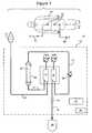
- FIGURE 1is a schematic diagram of an extracorporeal blood treatment system configured to detect or verify a type of blood circuit attached to the console.
- FIGURE 2is a schematic diagram of a portion of the extracorporeal blood treatment system shown in Figure 1 .
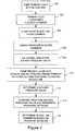
- FIGURE 3is a flow chart of steps performed by a controller of the extracorporeal blood circuit for' detecting or verifying a type of blood circuit attached to the console.
- FIGURE 1shows schematically a blood treatment system 10 coupled to a priming bag 12 filled with a saline solution.
- the figurehas been simplified to exclude components of the blood treatment system not pertinent to this description.
- the priming bag 12is used to purge the passages of the blood circuit in the system of air and contaminates before starting blood treatment.
- the blood treatment system 10is conventional with the exception of the shut-off device 14, such as a clamp or, valve, on the blood access line 16.
- the program instructions for detecting the blood circuit stored in a controller 18are not conventional.
- a nurse or other medical professionalBefore blood is withdrawn from the patient into the blood treatment system 10, a nurse or other medical professional connects the priming bag 12 to the blood return line 20 for the blood circuit. After priming, the blood return line 20 is disconnected from the priming bag and connected via access ports 22 to the vascular system of the patient 24.
- the blood return line 20is connected to a first bubble trap 26. Priming fluid flow from the first bubble trap through a blood pump line 17 to a blood chamber 28, also referred to as an arterial chamber, of a blood treatment device 30.
- the blood pump line 17provides a passage for blood from the blood chamber 28 to flow to a second bubble trap 34.
- the first and second bubble traps 26, 34may each have an associated pressure sensor 50a, 50b. Each pressure sensor 50a, 50b generates data indicating a pressure in its respective bubble trap, such as a gas pressure in an upper region of the bubble trap.
- the blood pump line 17is coupled to a peristaltic blood pump 32, such as a roller pump.
- the pump 32moves the priming liquid through the blood lines 20, 17 to the second bubble trap 34.
- the priming fluidflows from the second bubble trap to a blood access line 16 and to a drain or collection bag 38.
- the return line 20is disconnected from the priming bag 12 and connected to the access port 22 to infuse treated blood from the blood circuit into the patient 24, the access line 16 is separated from the drain or collection bag 38 and connected to an access port 22 to withdraw blood from the patient to the blood circuit.
- the blood circuit or portions thereofmay be releasably connected to a control and pumping console 42 that includes a least one pump 32, a controller 18 and a user interface 44 such as a display and keypad.
- the user interfaceallows an operator to input operating parameters for the blood treatment and monitor the blood treatment and other processes performed by the system 10. These operating parameters, e.g., settings, may depend on whether an adult or pediatric blood circuit is to be used in the blood treatment.
- the controller 18may generally include a computer or other processor and non-transitory computer memory storing program instructions for controlling the pumps and other controllable features of the system.
- the computer or processorexecutes the program instructions to control the pumps to prime the blood circuit, regulate blood treatment and (of particular relevance to the present invention) to detect or verify the type of blood circuit attached to the console.
- FIGURE 2is a schematic diagram of a portion of the blood treatment system 10 shown in Figure 1 .
- Figure 2illustrates an example of a bubble trap 26, 34 having a blood chamber 46 which includes an upper air or gas filled portion 48.
- a pressure sensor 50a, 50bis mounted to the bubble trap 26, 34 and monitors the fluid pressure in the blood chamber 46 and particularly the air filled portion 48 of that chamber.
- shut-off device 14While the shut-off device 14 is open, priming fluid drains from the blood chamber 46 and flows to a drain or collection bag 38 or other drainage collection vessel.
- the pump 32is stopped and the shut-off device is closed 14 to block the drainage of priming fluid from the chamber and to retain a portion of the priming fluid in the blood circuit.
- the shut-off deviceshould be closed quickly after the pump is stopped to ensure that the blood circuit is substantially filled with priming fluid, except for the gas filled region of the second bubble trap.
- the shut-off devicemay be automatically shut by the controller 18 in conjunction with the stopping of the pump 32. Alternatively, the shut-off device may be manually closed in response to an audiovisual prompt generated by the controller. After the pump is stopped and the shut-off device is closed, a first pressure level is measured by the pressure sensor 50b mounted to the second bubble trap 46.
- the blood pumpmay pump a predetermined additional amount of priming fluid such that at least some of the additional priming fluid enters the chamber 46 of the second bubble trap 34.
- the pressure in the chamber 46rises as the additional priming fluid enters the chamber because the fluid is prevented from draining due to the closed shut-off device. Assuming that the chamber 46 has a gas filled portion 48, the pressure in the chamber should rise in direct proportion to the amount of priming fluid entering the chamber.
- the volume of the gas filled portionis reduced in proportion to the amount of priming fluid entering the chamber while the shut-off device 14 is closed.
- the pumpingmay be at a predetermined rate and period to add priming fluid to the chamber while the shut-off device is closed.
- the amount of priming fluid addeddepends on the diameter of the return line 20.
- the short blood lines 17may be ignored due their relatively small volume. The larger the diameter of the return line, the greater the amount of priming fluid moved with each rotation of the pump 32.
- the pressure in the chamber 46will also depend on the diameter of the blood lines, e.g., the blood return line 20.
- the pressure rise in the chamber 46indicates the diameter of the blood return line 20 provided that the pumping of priming fluid into the chamber while the shut-off device is closed is controlled.
- the controlmay be to cause a predetermined pumping displacement, such as turning the pump through a half or quarter rotation.
- FIGURE 3is a flow chart showing exemplary control steps that are executed by the controller to detect or verify the type of blood circuit.
- step 100the controller operates the blood pump 32 to pump priming liquid from the priming bag 12 through the blood return line 20, blood treatment device 30, blood pump access line 16 and into the blood chamber 46 of the second bubble trap 34.
- step 102the priming liquid flows from the blood chamber 46 and into and through the blood access line 16, and is collected in the drain or collection bag 38.
- step 104the blood pump is stopped and the shut-off device shut to close the access line 16.
- step 106the controller 18 collects a first set of pressure data from a pressure sensor 50b monitoring pressure in the blood chamber 46, or a pressure in another portion of the blood circuit. Step 106 may be performed while the shut-off device is closed and the pump is stopped.
- step 108the controller 18 determines and stores a first pressure value based on the first pressure data.
- the first pressure levelmay alternatively be measured while the pump is turning and the shut-off device opened.
- the pumpmay be stopped and the shut-off device closed after the first pressure level is measured.
- the closing of the shut-off devicemay affect the pressure in the line and be a factor in determining the pressure differential between the first and second pressure levels.
- step 110while the shut-off device is closed, the controller controls the blood pump 32 to pump a predetermined amount of additional priming liquid into the return line 20, bubble trap 34 and a portion of the access line 16 upstream of the shut-off device 14.
- the blood pump 32is controlled to turn through a predetermined angle or number of rotations such that a predetermined amount of additional priming liquid is pumped into the blood circuit.
- the blood pumpmay controlled to turn a quarter or half turn to pump additional priming fluid into the blood chamber and raise the pressure in the lines 20, 17 and second bubble trap 34.
- step 112the controller 18 collects second pressure data generated by the pressure sensor 50b while the shut-off device 14 remains closed.
- the second pressure datais collection while the additional priming liquid remains in the access line, the blood treatment device and blood passage.
- a second pressure valueis determined by the controller based on the second pressure data.
- the first set of pressure datamay be stored in non-tangible computer memory assessable by a processor associated with the controller.
- the processorexecutes program instructions stored in the memory which cause the processor to control the pump and'console to perform the steps shown in Figure 3 .
- step 114the controller compares the first pressure value and the second pressure value to determine the pressure increase due to the additional predetermined amount of liquid added to the blood circuit in step 110. This determination may be based on whether the pressure increase is'within a predetermined range corresponding to an adult blood circuit or a predetermined range corresponding to a non-adult blood circuit, such as a pediatric blood circuit.
- the pressure increaseis dependent on the volume of the return line, which is dependent on the diameter of the return line.
- the pressure increasecan be used to determine the diameter of a line in the blood circuit, which indicates the type of blood circuit connected to the console. By indicating the diameter of a blood line, the pressure increase can be used by the controller to determine a dimensional characteristic of the blood passage.
- step 110may be performed by controlling the blood pump to pump the priming fluid until the pressure in the blood chamber 46 reaches a predetermined level.
- the controllerdetermines the amount of pumping, such as by determining the amount of rotation of the blood pump during step 110. For a small diameter return line, the pump rotation will be less to reach a predetermined pressure than the amount of pump rotation needed to increase the pressure in a large diameter a line.
- the amount of pump rotation needed to reach a predetermine pressure riseis an alternative method to determine the dimensional characteristic of the blood access line.
- the types of releasable blood circuits which may be attached to the consolemay include an adult circuit suitable for performing treatments on adult patients (large diameter blood line for adults), and a pediatric circuit suitable for performing treatment on child patients (pediatric blood line are relatively small diameter tubes). These two types of blood circuits, for adults and children, differ in the internal diameter of the access line. The diameter of the access line is greater in blood circuits for adults and is smaller for pediatric blood circuits.
- the settings or desired values of the flow rates of the blood pump and others pumps on the console for pumping the various fluids to be used in the blood treatmentare lower than the corresponding settings or desired values for a treatment destined for an adult.
- the steps show in Figure 3may be used by the controller to automatically determine and recognize the type of blood circuit attached to the console. Alternatively, the steps may be used by the controller to verify that the type of blood circuit mounted to the console is the same blood circuit type which the operated identified while inputting the parameters to the user interface 44.
- the controllermay operates an automatic intervention, e.g. a stop of the priming procedure or issue an alert to the user.
- the detection and verification process herein describedenables the controller to recognize whether an extracorporeal blood circuit of the disposable type for adults has been mounted on the treatment apparatus in the place of one for children, and vice versa. In this way an accidental exchange of circuits, which could cause damage to a patient, can be avoided.
Landscapes
- Health & Medical Sciences (AREA)
- Heart & Thoracic Surgery (AREA)
- Vascular Medicine (AREA)
- Life Sciences & Earth Sciences (AREA)
- General Health & Medical Sciences (AREA)
- Anesthesiology (AREA)
- Biomedical Technology (AREA)
- Hematology (AREA)
- Veterinary Medicine (AREA)
- Animal Behavior & Ethology (AREA)
- Engineering & Computer Science (AREA)
- Public Health (AREA)
- Cardiology (AREA)
- Urology & Nephrology (AREA)
- Emergency Medicine (AREA)
- Physics & Mathematics (AREA)
- General Physics & Mathematics (AREA)
- External Artificial Organs (AREA)
Description
- The invention relates to extracorporeal blood treatment systems and particularly to connecting a releasable blood circuit to a blood treatment console. The invention may be applied to determine or verify the type or size of disposable extracorporeal circuit coupled to a blood treatment console.
- An extracorporeal blood treatment system may include a blood treatment or blood collection console (referred to herein as a blood treatment console) and a disposable blood circuit that connects to they console. The blood circuit typically includes all or a portion of a blood passage having an access line (such as a flexible plastic tube, conduit or other liquid passage) into which blood is withdrawn from a patient and a return line through which treated blood is infused to the patient. The blood circuit is typically releasably connected to the blood treatment console.
- The blood treatment console may be used with various types of blood circuits, such as adult and non-adult, e.g. pediatric, blood circuits.. When a blood circuit is attached, the console should be properly configured manually or automatically to operate with the attached blood circuit. The operational settings for the console may depend on the type of blood circuit that is attached. For example, the pump speed for moving blood through the circuit and pressure levels in the circuit may differ for an adult blood circuit and a non-adult, e.g. pediatric blood circuit. Operational settings appropriate for one type of blood circuit may not be appropriate for another type of blood circuit.
- The operational settings for a console may be set manually by an operator, such as by nurse or other health care provider. The console may offer the operator a selection of settings and prompt the operator to enter operational settings for a blood treatment to be performed on a patient. The console operator typically presses buttons, soft keys, a touch screen or other input devices on the console to select the operational settings appropriate for the blood circuit and patient. The operator also loads the blood circuit' onto the console, such as by connecting blood lines in the circuit to the console. The operator may also connect the blood lines to the patient, such as by connecting the access and return blood lines to catheters or needles inserted in the vascular system of the patient.
- The console operators are generally medical professions who are trained in the operation of the blood treatment system, especially in how to select the correct operational settings for the console and the proper the blood circuit. Nevertheless, there is a possibility that the operation settings for one blood circuit may be inadvertently used for a different type of blood circuit.
- It is important that the operation settings inputted to or automatically selected by the console correspond to the type of blood circuit connected to the console. For example, when a pediatric blood circuit is connected to the console the operational settings of the console should be for a pediatric patient.
- Certain techniques have been published to detect the type of blood circuit attached to a blood treatment console. By way of example,
WO 2008/125894 andU.S. Patent Application Publication 2010/0114005 disclose techniques for detecting the type of blood circuit attached to a blood console. An apparatus for controlling an extracorporeal system, including automatically selecting proper console settings, is disclosed inWO 2006/123197 .WO 2009/051669 discloses an enclosure for containing a hemodialysis unit that includes a housing suitable to support components for performing hemodialysis including a dialyzer, one or more pumps to circulate blood through the dialyzer, a source of dialysate, and one or more pumps to circulate the dialysate through the dialyzer. The housing may have a front panel at which blood circuit connections and dialysate fluidic connections are located, e.g., blood line connections for patient blood access, connections for a reagent supply, dialyzer connections for both blood flow and dialysate, etc. For example, the blood flow pump may comprise two (or more) pod pumps. Each pod pump includes a rigid chamber with a flexible diaphragm or membrane dividing each chamber into a pumping compartment and control compartment. There are four entry/exit valves for these compartments, two for the pumping compartment and two for the control compartment. The valves for the control compartment of the chambers are two-way proportional valves, one connected to a first control fluid source (e.g., a high pressure air source), and the other connected to a second control fluid source (e.g., a low pressure air source) or a vacuum source. The fluid valves can be opened and closed to direct fluid flow when the pod pumps are operating. A volume calculation cycle involves determining and re-determining the volume of the pump chamber at different conditions and comparing the volumes determined at the different conditions. Even with these existing techniques, there remains a need and desire for devices and methods that accurately, simply and quickly detect the type of blood circuit connected to a blood console or verifying that the blood circuit connected to the console corresponds to the operational settings of the console. - It is desirable that the blood treatment system automatically selected the proper operational settings upon detecting that a blood circuit has been connected to the console. Alternatively, it is desirable that the blood treatment system automatically verify that settings manually programmed into the console by an operator are proper for the blood circuit attached to the console. It is also desirable that the selection or verification of the blood circuit occur before the blood circuit is coupled to the patient for blood treatment.
- The invention is defined by the independent claims.
- An extracorporeal blood treatment system and method have been invented and are disclosed herein which automatically recognizes the type of extracorporeal circuit applied to the console of the system. The system and method disclosed herein may be applied to program the console with the operational settings proper for the type of blood circuit connected to the console. The disclosed system and method may also be applied to verify that operational settings programmed into the console are proper for the type of blood circuit connected to the console.
- The disclosed system and method may be applied to detect or verify whether the blood circuit connected to the console is suitable for an adult patient or a pediatric patient. The disclosed system and method may be applied alone or in combination with other systems for detecting or verifying the type of blood circuit attached to a console.
- An novel apparatus has been conceived and is disclosed herein including at least one pump and a controller, the pump being connectable to an extracorporeal blood circuit including a blood access or return passage, a blood passage coupled to the pump, wherein the blood passage includes a chamber having an gas filled portion, and the controller: controls the pump to pump a liquid into the blood return or access passage and the blood passage; closes the return or access passage or issues a prompt to close the passage, after the passages are filled with the liquid; receives first pressure data from the pressure sensor while the pump is stopped and the shut-off device connected to the blood passage remains closed; determines a first pressure value based on the first pressure data; while the shut-off device is closed, controls the pump to pump an additional amount of the liquid into the passages; receives second pressure data generated by the pressure sensor while the shut-off device remains closed and the additional amount of the liquid is pumped in the passages; determines a second pressure value based on the second pressure data,
and determines a dimensional characteristic of the blood passage based on the second pressure value and the additional amount of the liquid. - The additional amount of the liquid may be determined by a predetermined pumping operation, and the dimensional characteristic of the blood passage may be determined based on a comparison of the first pressure value and the second pressure value. The dimensional characteristic of the blood passage may be alternatively determined based on the additional amount of the fluid pumped to cause the second pressure value to reach a predetermined pressure value. The liquid may be a priming liquid drawn from a source of the priming liquid connectable to the blood passage.
- The dimensional characteristic may be a diameter of the blood passage. The blood passage may be a blood tube for withdrawing blood from the patient.
- The controller may further cause the console to generate an audible or visual signal indicative of the determined dimensional characteristic. The audible or visual signal may indicate whether the blood passage is for an adult blood circuit or a non-adult blood circuit. The console may display or report a type of the extracorporeal circuit corresponding to the.determination of the dimensional characteristic. The controller may verify whether the determined dimensional characteristic is within a predetermined range of dimensional characteristics associated with an operational setting of the console.
- The pump may be a peristaltic pump. The predetermine amount of the liquid may be based on pumping the liquid at a predetermined rate and for a predetermined period. The blood treatment device may attach to the console separately from the blood passage. The pressure sensor may be mounted.on at least one of the extracorporeal blood treatment console, the blood treatment device, bubble trap and the blood circuit. The apparatus may be a hemodialysis apparatus or an hemo(dia)filtration apparatus. The shut-off device may be a clamp attached to the blood passage.
- The controller may include a non-transitory memory and a processor executing program instructions stored in the memory. The program instructions cause the controller to operate the pump, receive pressure data from the pressure sensor and generate displays or reports.
- An apparatus for extracorporeal blood treatment has been conceived and is disclosed herein comprising: an extracorporeal blood treatment console including a pump and a controller; a blood circuit including access and return passages and a blood passage, wherein the access passage is adapted to receive blood from a vascular system of a mammalian patient, the blood passage receives blood from the access passage and the return passages coveys treated blood to be infused to the patient, the passages include one or more blood chambers having a gas filled region; a peristaltic pump associated with the extracorporeal blood treatment console, wherein at least one of the blood passages is connected to the pump when the extracorporeal circuit connects to the extracorporeal blood treatment console;' a source of priming fluid; a pressure sensor generating pressure data indicative of a pressure in the blood passage; the controller controlling the peristaltic pump and receiving the pressure data, wherein the controller: controls the pump to pump a liquid into the return passage; closes the access passage downstream of the blood chamber or prompts closure of access passage downstream of the blood chamber; receives first pressure data while the pump is stopped and after the closure of the access passage; determines and stores a first pressure value based on the first pressure data; while the shut-off device is closed, controls the pump to perform a predetermined pumping operation to pump an additional amount of the liquid into the passages or to pump an additional amount of the liquid until the pressure detected by the pressure sensor reaches a predetermined pressure value; collects second pressure data generated by the pressure sensor while the shut-off device remains closed and the additional amount of the liquid is in the passages and chamber; determines a second pressure value based on the second pressure data or determines the additional amount of the liquid, and determines a dimensional characteristic of the blood passage based on a comparison of the first pressure value and the second pressure value or based on the additional amount of the liquid pumped to reach the predetermined pressure value.
- A method has been conceived and is disclosed herein to determine a type of blood circuit attached to an extracorporeal blood treatment console having a pump, the circuit including a first blood passage and a second blood passage connectable to the pump and including a chamber having a gas filled region, the method comprises: pumping a liquid into the first blood passage, wherein the pumped liquid flows through the second blood passage; closing the second blood passage downstream of the chamber after the first blood passage and second blood passage fills with the liquid; sensing a first pressure of the liquid while the liquid is in the first and second blood passages, the pump is stopped and the second blood passage remains closed; after sensing the first pressure and while the second passage remains closed, pumping an additional amount of the liquid into the first blood passage; sensing a second pressure while the additional amount of liquid remains in the first and second blood passages and while the second blood passage remains closed; determining a dimensional characteristic of one of the blood passages based on the second pressure and the amount of the additional liquid.
- The description will be made with reference to the accompanying figures of the drawings, provided by way of non-limiting example, in which:
FIGURE 1 is a schematic diagram of an extracorporeal blood treatment system configured to detect or verify a type of blood circuit attached to the console.FIGURE 2 is a schematic diagram of a portion of the extracorporeal blood treatment system shown inFigure 1 .FIGURE 3 is a flow chart of steps performed by a controller of the extracorporeal blood circuit for' detecting or verifying a type of blood circuit attached to the console.FIGURE 1 shows schematically ablood treatment system 10 coupled to a primingbag 12 filled with a saline solution. The figure has been simplified to exclude components of the blood treatment system not pertinent to this description. The primingbag 12 is used to purge the passages of the blood circuit in the system of air and contaminates before starting blood treatment. Theblood treatment system 10 is conventional with the exception of the shut-offdevice 14, such as a clamp or, valve, on theblood access line 16. In addition, the program instructions for detecting the blood circuit stored in acontroller 18 are not conventional.- Before blood is withdrawn from the patient into the
blood treatment system 10, a nurse or other medical professional connects the primingbag 12 to theblood return line 20 for the blood circuit. After priming, theblood return line 20 is disconnected from the priming bag and connected viaaccess ports 22 to the vascular system of thepatient 24. - The
blood return line 20 is connected to a first bubble trap 26. Priming fluid flow from the first bubble trap through ablood pump line 17 to ablood chamber 28, also referred to as an arterial chamber, of ablood treatment device 30. Theblood pump line 17 provides a passage for blood from theblood chamber 28 to flow to asecond bubble trap 34. The first and second bubble traps 26, 34 may each have an associated pressure sensor 50a, 50b. Each pressure sensor 50a, 50b generates data indicating a pressure in its respective bubble trap, such as a gas pressure in an upper region of the bubble trap. - The
blood pump line 17 is coupled to aperistaltic blood pump 32, such as a roller pump. Thepump 32 moves the priming liquid through theblood lines second bubble trap 34. The priming fluid flows from the second bubble trap to ablood access line 16 and to a drain or collection bag 38. Theblood return line 20, first bubble trap 26,blood chamber 28,blood pump line 17,second bubble trap 34 and theblood access line 16 blood circuit, e.g., blood flow passage, through the extracorporeal blood treatment device. - After the
blood treatment system 10 has been primed by filling priming liquid in all lines of at least the blood circuit, thereturn line 20 is disconnected from the primingbag 12 and connected to theaccess port 22 to infuse treated blood from the blood circuit into thepatient 24, theaccess line 16 is separated from the drain or collection bag 38 and connected to anaccess port 22 to withdraw blood from the patient to the blood circuit. - The blood circuit or portions thereof may be releasably connected to a control and pumping
console 42 that includes a least onepump 32, acontroller 18 and auser interface 44 such as a display and keypad. The user interface allows an operator to input operating parameters for the blood treatment and monitor the blood treatment and other processes performed by thesystem 10. These operating parameters, e.g., settings, may depend on whether an adult or pediatric blood circuit is to be used in the blood treatment. - The
controller 18 may generally include a computer or other processor and non-transitory computer memory storing program instructions for controlling the pumps and other controllable features of the system. The computer or processor executes the program instructions to control the pumps to prime the blood circuit, regulate blood treatment and (of particular relevance to the present invention) to detect or verify the type of blood circuit attached to the console. FIGURE 2 is a schematic diagram of a portion of theblood treatment system 10 shown inFigure 1 .Figure 2 illustrates an example of abubble trap 26, 34 having ablood chamber 46 which includes an upper air or gas filledportion 48. A pressure sensor 50a, 50b is mounted to thebubble trap 26, 34 and monitors the fluid pressure in theblood chamber 46 and particularly the air filledportion 48 of that chamber.- While the shut-off
device 14 is open, priming fluid drains from theblood chamber 46 and flows to a drain or collection bag 38 or other drainage collection vessel. Thepump 32 is stopped and the shut-off device is closed 14 to block the drainage of priming fluid from the chamber and to retain a portion of the priming fluid in the blood circuit. The shut-off device should be closed quickly after the pump is stopped to ensure that the blood circuit is substantially filled with priming fluid, except for the gas filled region of the second bubble trap. The shut-off device may be automatically shut by thecontroller 18 in conjunction with the stopping of thepump 32. Alternatively, the shut-off device may be manually closed in response to an audiovisual prompt generated by the controller. After the pump is stopped and the shut-off device is closed, a first pressure level is measured by the pressure sensor 50b mounted to thesecond bubble trap 46. - After the first pressure level is measured and the shut-off device closed, the blood pump may pump a predetermined additional amount of priming fluid such that at least some of the additional priming fluid enters the
chamber 46 of thesecond bubble trap 34. The pressure in thechamber 46 rises as the additional priming fluid enters the chamber because the fluid is prevented from draining due to the closed shut-off device. Assuming that thechamber 46 has a gas filledportion 48, the pressure in the chamber should rise in direct proportion to the amount of priming fluid entering the chamber. - As the priming fluid enters the
chamber 46, the volume of thegas portion 48 is reduced. Boyle's Law states that for a compressible gas the product of the pressure and volume is a constant (P x V = K). Accordingly, the reduction of the volume of thegas portion 48 in the chamber should result in a proportional rise in the pressure as sensed by the pressure sensor 50b. - The volume of the gas filled portion is reduced in proportion to the amount of priming fluid entering the chamber while the shut-off
device 14 is closed. The pumping may be at a predetermined rate and period to add priming fluid to the chamber while the shut-off device is closed. The amount of priming fluid added depends on the diameter of thereturn line 20. Theshort blood lines 17 may be ignored due their relatively small volume. The larger the diameter of the return line, the greater the amount of priming fluid moved with each rotation of thepump 32. - Because the amount of priming fluid added to the
chamber 46 of thebubble trap 34 while the shut-offdevice 14 is closed depends on the diameter of the blood lines, the pressure in thechamber 46 will also depend on the diameter of the blood lines, e.g., theblood return line 20. The pressure rise in thechamber 46 indicates the diameter of theblood return line 20 provided that the pumping of priming fluid into the chamber while the shut-off device is closed is controlled. In one example, the control may be to cause a predetermined pumping displacement, such as turning the pump through a half or quarter rotation. FIGURE 3 is a flow chart showing exemplary control steps that are executed by the controller to detect or verify the type of blood circuit.- In
step 100, the controller operates theblood pump 32 to pump priming liquid from the primingbag 12 through theblood return line 20,blood treatment device 30, bloodpump access line 16 and into theblood chamber 46 of thesecond bubble trap 34. Instep 102, the priming liquid flows from theblood chamber 46 and into and through theblood access line 16, and is collected in the drain or collection bag 38. - In
step 104, the blood pump is stopped and the shut-off device shut to close theaccess line 16. Instep 106, thecontroller 18 collects a first set of pressure data from a pressure sensor 50b monitoring pressure in theblood chamber 46, or a pressure in another portion of the blood circuit. Step 106 may be performed while the shut-off device is closed and the pump is stopped. - In
step 108, thecontroller 18 determines and stores a first pressure value based on the first pressure data. - The first pressure level may alternatively be measured while the pump is turning and the shut-off device opened. In this alternative pressure measurement, the pump may be stopped and the shut-off device closed after the first pressure level is measured. However, the closing of the shut-off device may affect the pressure in the line and be a factor in determining the pressure differential between the first and second pressure levels.
- In
step 110, while the shut-off device is closed, the controller controls theblood pump 32 to pump a predetermined amount of additional priming liquid into thereturn line 20,bubble trap 34 and a portion of theaccess line 16 upstream of the shut-offdevice 14. Theblood pump 32 is controlled to turn through a predetermined angle or number of rotations such that a predetermined amount of additional priming liquid is pumped into the blood circuit. For example, the blood pump may controlled to turn a quarter or half turn to pump additional priming fluid into the blood chamber and raise the pressure in thelines second bubble trap 34. - In
step 112, thecontroller 18 collects second pressure data generated by the pressure sensor 50b while the shut-offdevice 14 remains closed. The second pressure data is collection while the additional priming liquid remains in the access line, the blood treatment device and blood passage. A second pressure value is determined by the controller based on the second pressure data. The first set of pressure data may be stored in non-tangible computer memory assessable by a processor associated with the controller. The processor executes program instructions stored in the memory which cause the processor to control the pump and'console to perform the steps shown inFigure 3 . - In
step 114, the controller compares the first pressure value and the second pressure value to determine the pressure increase due to the additional predetermined amount of liquid added to the blood circuit instep 110. This determination may be based on whether the pressure increase is'within a predetermined range corresponding to an adult blood circuit or a predetermined range corresponding to a non-adult blood circuit, such as a pediatric blood circuit. - The pressure increase is dependent on the volume of the return line, which is dependent on the diameter of the return line. The pressure increase can be used to determine the diameter of a line in the blood circuit, which indicates the type of blood circuit connected to the console. By indicating the diameter of a blood line, the pressure increase can be used by the controller to determine a dimensional characteristic of the blood passage.
- Alternatively, step 110 may be performed by controlling the blood pump to pump the priming fluid until the pressure in the
blood chamber 46 reaches a predetermined level. When the predetermined pressure level is reached, the controller determines the amount of pumping, such as by determining the amount of rotation of the blood pump duringstep 110. For a small diameter return line, the pump rotation will be less to reach a predetermined pressure than the amount of pump rotation needed to increase the pressure in a large diameter a line. The amount of pump rotation needed to reach a predetermine pressure rise is an alternative method to determine the dimensional characteristic of the blood access line. - The types of releasable blood circuits which may be attached to the console may include an adult circuit suitable for performing treatments on adult patients (large diameter blood line for adults), and a pediatric circuit suitable for performing treatment on child patients (pediatric blood line are relatively small diameter tubes). These two types of blood circuits, for adults and children, differ in the internal diameter of the access line. The diameter of the access line is greater in blood circuits for adults and is smaller for pediatric blood circuits.
- In setting-up of the console for an extracorporeal treatment for a child in general, the settings or desired values of the flow rates of the blood pump and others pumps on the console for pumping the various fluids to be used in the blood treatment (blood flow rate, anticoagulant flow rate, dialysis fluid flow rate, replacement fluid flow rate, infusion fluid flow rate etc.) are lower than the corresponding settings or desired values for a treatment destined for an adult.
- The steps show in
Figure 3 may be used by the controller to automatically determine and recognize the type of blood circuit attached to the console. Alternatively, the steps may be used by the controller to verify that the type of blood circuit mounted to the console is the same blood circuit type which the operated identified while inputting the parameters to theuser interface 44. - If the detection or verification process shown in
Figure 3 recognizes that the blood circuit matches the adult/child selection made by the operator, no alert (audible or visual) to the operator is generated by the controller. If the detection verification process determines that the blood circuit does not match the type of blood circuit selected by the operator using the user interface, the controller may operates an automatic intervention, e.g. a stop of the priming procedure or issue an alert to the user. - The detection and verification process herein described enables the controller to recognize whether an extracorporeal blood circuit of the disposable type for adults has been mounted on the treatment apparatus in the place of one for children, and vice versa. In this way an accidental exchange of circuits, which could cause damage to a patient, can be avoided.
- While the invention has been described in connection with what is presently considered to be the most practical and preferred embodiment, it is to be understood that the invention is not to be limited to the disclosed embodiment, but on the contrary, is intended to cover various modifications and equivalent arrangements included within the appended claims.
Claims (7)
- An apparatus for extracorporeal blood treatment comprising:an extracorporeal blood treatment console (42) including a controller (18);a blood circuit including an blood passage having a blood return line (20) adapted to convey treated blood to be infused in a mammalian patient, a blood pump line (17) coupled to a blood chamber (34) having a gas filled region (48) and a blood access line (16) adapted to receive blood withdrawn from the patient;a peristaltic pump (32) associated with the extracorporeal blood treatment console (42) and adapted to connect to the blood pump line (17) of the blood passage;a source (12) of priming fluid;a pressure sensor (50b) generating pressure data indicative of a pressure in the blood chamber (34);the controller (18) controlling the peristaltic pump (32) and receiving the pressure data, wherein the controller (18) is configured to perform the following step:a. controlling the pump (32) to pump the priming fluid into the blood passage;
characterized in that the apparatus comprises a shut off device (14) andin that the controller (18) is configured to perform the following steps:b. stopping the pump and closing the blood passage downstream of the blood chamber by means of the shut-off device (14) or prompting closure of blood passage downstream of the blood chamber;c. receiving first pressure data while the pump (32) is stopped and after the closure of the blood passage;d. determining and storing a first pressure value based on the first pressure data;e. while the shut-off device (14) is closed, controlling the pump (32) to perform a predetermined pumping operation to pump an additional amount of the priming fluid into the blood passage or to pump an additional amount of the priming fluid until the pressure detected by the pressure sensor reaches a predetermined pressure value;f. collecting second pressure data generated by the pressure sensor (50b) while the shut-off device (14) remains closed and the additional amount of the priming fluid is in the blood passage;g. determining a second pressure value based on the second pressure data or determining the additional amount of the priming fluid, andh. determining a dimensional characteristic of the blood passage based on a comparison of the first pressure value and the second pressure value or based on the additional amount of the liquid pumped to reach the predetermined pressure value. - The apparatus of claim 1 wherein the dimensional characteristic is a diameter of the blood passage.
- The apparatus of any of claims 1 to 2 wherein the controller (18) generates an audible or visual signal indicative of whether the blood passage is for an adult blood circuit or a non-adult blood circuit.
- The extracorporeal blood treatment console of any of claims 1 to 3 wherein the controller (18) generates an audible or visual signal indicative of the determined dimensional characteristic.
- The extracorporeal blood treatment console of any of claims 1 to 4 wherein the controller verifies whether the determined dimensional characteristic is within a predetermined range of dimensional characteristics associated with an operational setting of the console (18).
- A method to determine a type of blood circuit attached to an extracorporeal blood treatment console (18) having a pump (32), the circuit including a blood passage and a chamber (34) having a gas filled region (48) and in blood fluid communication with the blood passage,characterized in that the method comprises:pumping a liquid into the blood passage;closing the blood passage downstream of the chamber (34) after the liquid is pumped into the blood passage;sensing a first pressure of the chamber (34) while the liquid is in the blood passage, the pump (32) is stopped and the passage remains closed;after sensing the first pressure and while the passage remains closed, pumping an additional amount of the liquid into the blood passage;sensing a second pressure while the additional amount of liquid remains in the blood passage and chamber (34), and while the blood passage remains closed, anddetermining a dimensional characteristic of the blood passage based on the second pressure and the amount of the additional liquid;wherein the additional amount of liquid is pumped until the second pressure reaches a predetermined pressure value and the determination of the dimensional characteristic is based on a determination of the volume of the additional amount of the liquid pumped; orwherein the additional amount of liquid is pumped for a predetermined pumping displacement and a comparison is made of the first and second pressures to determine the dimensional characteristic.
- The method of claim 6 wherein the pumping at the predetermined pumping rate and for a predetermined pumping period is achieved by turning the pump (32) through a predetermined rotation.
Priority Applications (9)
| Application Number | Priority Date | Filing Date | Title |
|---|---|---|---|
| PL10015918TPL2468324T3 (en) | 2010-12-22 | 2010-12-22 | Method and system for detecting or verifying a blood circuit connected to an extracorporeal blood treatment console |
| EP10015918.5AEP2468324B1 (en) | 2010-12-22 | 2010-12-22 | Method and system for detecting or verifying a blood circuit connected to an extracorporeal blood treatment console |
| ES10015918.5TES2479618T3 (en) | 2010-12-22 | 2010-12-22 | Method and system to detect or verify a blood circuit connected to an extracorporeal blood treatment console |
| US13/997,532US9791270B2 (en) | 2010-12-22 | 2011-12-21 | Method and system for detecting or verifying a blood circuit connected to an extracorporeal blood treatment console |
| CN201180062467.3ACN103282062B (en) | 2010-12-22 | 2011-12-21 | Method and system for testing or validating a blood circuit connected to an extracorporeal blood processing console |
| CA2822015ACA2822015C (en) | 2010-12-22 | 2011-12-21 | Method and system for detecting or verifying a blood circuit connected to an extracorporeal blood treatment console |
| AU2011346745AAU2011346745B2 (en) | 2010-12-22 | 2011-12-21 | Method and system for detecting or verifying a blood circuit connected to an extracorporeal blood treatment console |
| KR1020137019337AKR101538875B1 (en) | 2010-12-22 | 2011-12-21 | Method and device for detecting or verifying a blood circuit connected to an extracorporeal blood treatment console |
| PCT/IB2011/003103WO2012085644A1 (en) | 2010-12-22 | 2011-12-21 | Method and system for detecting or verifying a blood circuit connected to an extracorporeal blood treatment console |
Applications Claiming Priority (1)
| Application Number | Priority Date | Filing Date | Title |
|---|---|---|---|
| EP10015918.5AEP2468324B1 (en) | 2010-12-22 | 2010-12-22 | Method and system for detecting or verifying a blood circuit connected to an extracorporeal blood treatment console |
Publications (2)
| Publication Number | Publication Date |
|---|---|
| EP2468324A1 EP2468324A1 (en) | 2012-06-27 |
| EP2468324B1true EP2468324B1 (en) | 2014-04-02 |
Family
ID=43982416
Family Applications (1)
| Application Number | Title | Priority Date | Filing Date |
|---|---|---|---|
| EP10015918.5AActiveEP2468324B1 (en) | 2010-12-22 | 2010-12-22 | Method and system for detecting or verifying a blood circuit connected to an extracorporeal blood treatment console |
Country Status (9)
| Country | Link |
|---|---|
| US (1) | US9791270B2 (en) |
| EP (1) | EP2468324B1 (en) |
| KR (1) | KR101538875B1 (en) |
| CN (1) | CN103282062B (en) |
| AU (1) | AU2011346745B2 (en) |
| CA (1) | CA2822015C (en) |
| ES (1) | ES2479618T3 (en) |
| PL (1) | PL2468324T3 (en) |
| WO (1) | WO2012085644A1 (en) |
Cited By (3)
| Publication number | Priority date | Publication date | Assignee | Title |
|---|---|---|---|---|
| US10279098B2 (en) | 2015-04-07 | 2019-05-07 | Nxstage Medical, Inc. | Blood treatment device priming devices, methods, and systems |
| US10345175B2 (en) | 2011-05-31 | 2019-07-09 | Nxstage Medical, Inc. | Pressure measurement devices, methods, and systems |
| US10864312B2 (en) | 2005-11-09 | 2020-12-15 | B. Braun Medical Inc. | Diaphragm pressure pod for medical fluids |
Families Citing this family (13)
| Publication number | Priority date | Publication date | Assignee | Title |
|---|---|---|---|---|
| WO2014093121A1 (en)* | 2012-12-12 | 2014-06-19 | Edwards Lifesciences Corporation | Analyte sensing system and method for controlling presentation of information |
| WO2014093170A1 (en)* | 2012-12-12 | 2014-06-19 | Edwards Lifesciences Corporation | System and method for detecting occlusions in a blood access device |
| EP2959927A1 (en)* | 2014-06-26 | 2015-12-30 | Medela Holding AG | Device for the extraction and forwarding of blood |
| EP3171916B1 (en)* | 2014-07-25 | 2021-12-15 | Kpr U.S., Llc | Flow detection system for flow control apparatus |
| KR102584051B1 (en)* | 2015-06-25 | 2023-09-27 | 감브로 룬디아 아베 | Detection of disruption of fluid communication between two fluid-containing systems |
| JP6111351B1 (en)* | 2016-01-25 | 2017-04-05 | 日機装株式会社 | Blood purification equipment |
| EP3498317A4 (en)* | 2016-08-09 | 2020-03-04 | Nikkiso Co., Ltd. | BLOOD CLEANING DEVICE AND PRIMING METHOD |
| US11590334B2 (en) | 2016-08-09 | 2023-02-28 | Nikkiso Co., Ltd. | Blood circuit adapter set and blood circuit |
| EP3348291B1 (en)* | 2017-01-12 | 2019-12-04 | Gambro Lundia AB | Extracorporeal blood treatment apparatus and method for checking the connection of a soft bag in an extracorporeal blood treatment apparatus |
| ES2933693T3 (en) | 2019-11-18 | 2023-02-13 | Eitan Medical Ltd | Rapid test for medical pump |
| US12318528B2 (en) | 2020-10-30 | 2025-06-03 | Mozarc Medical Us Llc | Variable orifice fistula graft |
| EP4523222A1 (en)* | 2022-05-12 | 2025-03-19 | Gambro Lundia AB | Configuration of a dialysis machine for extracorporeal blood therapy |
| EP4470574A1 (en)* | 2023-05-31 | 2024-12-04 | Fresenius Medical Care Deutschland GmbH | Apparatus and method for controlling a blood processing apparatus |
Family Cites Families (8)
| Publication number | Priority date | Publication date | Assignee | Title |
|---|---|---|---|---|
| WO2006123197A1 (en) | 2005-05-18 | 2006-11-23 | Gambro Lundia Ab | An apparatus for controlling blood flow in an extracorporeal circuit. |
| WO2007049092A1 (en) | 2005-10-27 | 2007-05-03 | Gambro Lundia Ab | Extracorporeal blood set |
| US8388567B2 (en) | 2007-04-12 | 2013-03-05 | Gambro Lundia Ab | Apparatus for extracorporeal blood treatment |
| DE102007024463A1 (en)* | 2007-05-25 | 2008-11-27 | Fresenius Medical Care Deutschland Gmbh | Method and device for checking the correct coupling of an adding device to a therapy device |
| CN101687069B (en)* | 2007-06-29 | 2013-01-16 | 株式会社Jms | Hemodialyzer |
| EP3037117B1 (en)* | 2007-10-12 | 2017-12-20 | DEKA Products Limited Partnership | Blood line connector |
| JP5595930B2 (en)* | 2008-01-23 | 2014-09-24 | デカ・プロダクツ・リミテッド・パートナーシップ | Disposable components for fluid line automatic connection systems |
| US9677555B2 (en) | 2011-12-21 | 2017-06-13 | Deka Products Limited Partnership | System, method, and apparatus for infusing fluid |
- 2010
- 2010-12-22EPEP10015918.5Apatent/EP2468324B1/enactiveActive
- 2010-12-22PLPL10015918Tpatent/PL2468324T3/enunknown
- 2010-12-22ESES10015918.5Tpatent/ES2479618T3/enactiveActive
- 2011
- 2011-12-21CACA2822015Apatent/CA2822015C/enactiveActive
- 2011-12-21AUAU2011346745Apatent/AU2011346745B2/enactiveActive
- 2011-12-21WOPCT/IB2011/003103patent/WO2012085644A1/enactiveApplication Filing
- 2011-12-21KRKR1020137019337Apatent/KR101538875B1/enactiveActive
- 2011-12-21USUS13/997,532patent/US9791270B2/enactiveActive
- 2011-12-21CNCN201180062467.3Apatent/CN103282062B/enactiveActive
Cited By (8)
| Publication number | Priority date | Publication date | Assignee | Title |
|---|---|---|---|---|
| US10864312B2 (en) | 2005-11-09 | 2020-12-15 | B. Braun Medical Inc. | Diaphragm pressure pod for medical fluids |
| US10345175B2 (en) | 2011-05-31 | 2019-07-09 | Nxstage Medical, Inc. | Pressure measurement devices, methods, and systems |
| US11529448B2 (en) | 2011-05-31 | 2022-12-20 | Nxstage Medical, Inc. | Pressure measurement devices, methods, and systems |
| US12171926B2 (en) | 2011-05-31 | 2024-12-24 | Nxstage Medical, Inc. | Pressure measurement devices, methods, and systems |
| US10279098B2 (en) | 2015-04-07 | 2019-05-07 | Nxstage Medical, Inc. | Blood treatment device priming devices, methods, and systems |
| US10987461B2 (en) | 2015-04-07 | 2021-04-27 | Nxstage Medical, Inc. | Blood treatment device priming devices, methods, and systems |
| US11679190B2 (en) | 2015-04-07 | 2023-06-20 | Nxstage Medical, Inc. | Blood treatment device priming devices, methods, and systems |
| US11969534B2 (en) | 2015-04-07 | 2024-04-30 | Nxstage Medical, Inc. | Blood treatment device priming devices, methods, and systems |
Also Published As
| Publication number | Publication date |
|---|---|
| KR101538875B1 (en) | 2015-07-22 |
| AU2011346745B2 (en) | 2015-06-11 |
| CN103282062B (en) | 2015-09-23 |
| CA2822015A1 (en) | 2012-06-28 |
| CA2822015C (en) | 2015-11-10 |
| PL2468324T3 (en) | 2014-06-30 |
| KR20130118354A (en) | 2013-10-29 |
| CN103282062A (en) | 2013-09-04 |
| ES2479618T3 (en) | 2014-07-24 |
| US9791270B2 (en) | 2017-10-17 |
| WO2012085644A1 (en) | 2012-06-28 |
| EP2468324A1 (en) | 2012-06-27 |
| AU2011346745A1 (en) | 2013-05-02 |
| US20140048460A1 (en) | 2014-02-20 |
Similar Documents
| Publication | Publication Date | Title |
|---|---|---|
| EP2468324B1 (en) | Method and system for detecting or verifying a blood circuit connected to an extracorporeal blood treatment console | |
| US10258733B2 (en) | Apparatus and method of controlling an extracorporeal blood treatment | |
| EP2142235B1 (en) | Apparatus for extracorporeal blood treatment | |
| CA2723978C (en) | A medical fluid circuit comprising a low level detector 1 | |
| US20100191164A1 (en) | Hemodialysis apparatus | |
| CN108601880A (en) | System and method for controlling venous air recovery in a portable dialysis system | |
| CA3060041C (en) | Apparatus and method to check extracorporeal circuit | |
| US11577012B2 (en) | Auto adjustment of blood treatment parameters based on patient comfort | |
| CN116887874A (en) | Method and device for evaluating measured pressure values | |
| KR102710202B1 (en) | Device for determining static pressure in peritoneal dialysis patients | |
| CA3208509A1 (en) | Device and method for disconnection |
Legal Events
| Date | Code | Title | Description |
|---|---|---|---|
| AK | Designated contracting states | Kind code of ref document:A1 Designated state(s):AL AT BE BG CH CY CZ DE DK EE ES FI FR GB GR HR HU IE IS IT LI LT LU LV MC MK MT NL NO PL PT RO RS SE SI SK SM TR | |
| AX | Request for extension of the european patent | Extension state:BA ME | |
| PUAI | Public reference made under article 153(3) epc to a published international application that has entered the european phase | Free format text:ORIGINAL CODE: 0009012 | |
| 17P | Request for examination filed | Effective date:20121019 | |
| 17Q | First examination report despatched | Effective date:20130326 | |
| GRAP | Despatch of communication of intention to grant a patent | Free format text:ORIGINAL CODE: EPIDOSNIGR1 | |
| INTG | Intention to grant announced | Effective date:20140107 | |
| GRAS | Grant fee paid | Free format text:ORIGINAL CODE: EPIDOSNIGR3 | |
| GRAA | (expected) grant | Free format text:ORIGINAL CODE: 0009210 | |
| AK | Designated contracting states | Kind code of ref document:B1 Designated state(s):AL AT BE BG CH CY CZ DE DK EE ES FI FR GB GR HR HU IE IS IT LI LT LU LV MC MK MT NL NO PL PT RO RS SE SI SK SM TR | |
| REG | Reference to a national code | Ref country code:GB Ref legal event code:FG4D | |
| REG | Reference to a national code | Ref country code:AT Ref legal event code:REF Ref document number:659689 Country of ref document:AT Kind code of ref document:T Effective date:20140415 Ref country code:CH Ref legal event code:EP | |
| REG | Reference to a national code | Ref country code:IE Ref legal event code:FG4D | |
| REG | Reference to a national code | Ref country code:DE Ref legal event code:R096 Ref document number:602010014727 Country of ref document:DE Effective date:20140515 | |
| REG | Reference to a national code | Ref country code:PL Ref legal event code:T3 | |
| REG | Reference to a national code | Ref country code:ES Ref legal event code:FG2A Ref document number:2479618 Country of ref document:ES Kind code of ref document:T3 Effective date:20140724 | |
| REG | Reference to a national code | Ref country code:AT Ref legal event code:MK05 Ref document number:659689 Country of ref document:AT Kind code of ref document:T Effective date:20140402 | |
| REG | Reference to a national code | Ref country code:NL Ref legal event code:VDEP Effective date:20140402 | |
| REG | Reference to a national code | Ref country code:LT Ref legal event code:MG4D | |
| PG25 | Lapsed in a contracting state [announced via postgrant information from national office to epo] | Ref country code:NO Free format text:LAPSE BECAUSE OF FAILURE TO SUBMIT A TRANSLATION OF THE DESCRIPTION OR TO PAY THE FEE WITHIN THE PRESCRIBED TIME-LIMIT Effective date:20140702 Ref country code:CZ Free format text:LAPSE BECAUSE OF FAILURE TO SUBMIT A TRANSLATION OF THE DESCRIPTION OR TO PAY THE FEE WITHIN THE PRESCRIBED TIME-LIMIT Effective date:20140402 Ref country code:FI Free format text:LAPSE BECAUSE OF FAILURE TO SUBMIT A TRANSLATION OF THE DESCRIPTION OR TO PAY THE FEE WITHIN THE PRESCRIBED TIME-LIMIT Effective date:20140402 Ref country code:NL Free format text:LAPSE BECAUSE OF FAILURE TO SUBMIT A TRANSLATION OF THE DESCRIPTION OR TO PAY THE FEE WITHIN THE PRESCRIBED TIME-LIMIT Effective date:20140402 Ref country code:IS Free format text:LAPSE BECAUSE OF FAILURE TO SUBMIT A TRANSLATION OF THE DESCRIPTION OR TO PAY THE FEE WITHIN THE PRESCRIBED TIME-LIMIT Effective date:20140802 Ref country code:CY Free format text:LAPSE BECAUSE OF FAILURE TO SUBMIT A TRANSLATION OF THE DESCRIPTION OR TO PAY THE FEE WITHIN THE PRESCRIBED TIME-LIMIT Effective date:20140402 Ref country code:BG Free format text:LAPSE BECAUSE OF FAILURE TO SUBMIT A TRANSLATION OF THE DESCRIPTION OR TO PAY THE FEE WITHIN THE PRESCRIBED TIME-LIMIT Effective date:20140702 Ref country code:LT Free format text:LAPSE BECAUSE OF FAILURE TO SUBMIT A TRANSLATION OF THE DESCRIPTION OR TO PAY THE FEE WITHIN THE PRESCRIBED TIME-LIMIT Effective date:20140402 Ref country code:GR Free format text:LAPSE BECAUSE OF FAILURE TO SUBMIT A TRANSLATION OF THE DESCRIPTION OR TO PAY THE FEE WITHIN THE PRESCRIBED TIME-LIMIT Effective date:20140703 | |
| PG25 | Lapsed in a contracting state [announced via postgrant information from national office to epo] | Ref country code:AT Free format text:LAPSE BECAUSE OF FAILURE TO SUBMIT A TRANSLATION OF THE DESCRIPTION OR TO PAY THE FEE WITHIN THE PRESCRIBED TIME-LIMIT Effective date:20140402 Ref country code:HR Free format text:LAPSE BECAUSE OF FAILURE TO SUBMIT A TRANSLATION OF THE DESCRIPTION OR TO PAY THE FEE WITHIN THE PRESCRIBED TIME-LIMIT Effective date:20140402 Ref country code:RS Free format text:LAPSE BECAUSE OF FAILURE TO SUBMIT A TRANSLATION OF THE DESCRIPTION OR TO PAY THE FEE WITHIN THE PRESCRIBED TIME-LIMIT Effective date:20140402 Ref country code:SE Free format text:LAPSE BECAUSE OF FAILURE TO SUBMIT A TRANSLATION OF THE DESCRIPTION OR TO PAY THE FEE WITHIN THE PRESCRIBED TIME-LIMIT Effective date:20140402 Ref country code:LV Free format text:LAPSE BECAUSE OF FAILURE TO SUBMIT A TRANSLATION OF THE DESCRIPTION OR TO PAY THE FEE WITHIN THE PRESCRIBED TIME-LIMIT Effective date:20140402 | |
| PG25 | Lapsed in a contracting state [announced via postgrant information from national office to epo] | Ref country code:PT Free format text:LAPSE BECAUSE OF FAILURE TO SUBMIT A TRANSLATION OF THE DESCRIPTION OR TO PAY THE FEE WITHIN THE PRESCRIBED TIME-LIMIT Effective date:20140804 | |
| REG | Reference to a national code | Ref country code:DE Ref legal event code:R097 Ref document number:602010014727 Country of ref document:DE | |
| PG25 | Lapsed in a contracting state [announced via postgrant information from national office to epo] | Ref country code:EE Free format text:LAPSE BECAUSE OF FAILURE TO SUBMIT A TRANSLATION OF THE DESCRIPTION OR TO PAY THE FEE WITHIN THE PRESCRIBED TIME-LIMIT Effective date:20140402 Ref country code:RO Free format text:LAPSE BECAUSE OF FAILURE TO SUBMIT A TRANSLATION OF THE DESCRIPTION OR TO PAY THE FEE WITHIN THE PRESCRIBED TIME-LIMIT Effective date:20140402 Ref country code:DK Free format text:LAPSE BECAUSE OF FAILURE TO SUBMIT A TRANSLATION OF THE DESCRIPTION OR TO PAY THE FEE WITHIN THE PRESCRIBED TIME-LIMIT Effective date:20140402 Ref country code:BE Free format text:LAPSE BECAUSE OF FAILURE TO SUBMIT A TRANSLATION OF THE DESCRIPTION OR TO PAY THE FEE WITHIN THE PRESCRIBED TIME-LIMIT Effective date:20140402 Ref country code:SK Free format text:LAPSE BECAUSE OF FAILURE TO SUBMIT A TRANSLATION OF THE DESCRIPTION OR TO PAY THE FEE WITHIN THE PRESCRIBED TIME-LIMIT Effective date:20140402 | |
| PLBE | No opposition filed within time limit | Free format text:ORIGINAL CODE: 0009261 | |
| STAA | Information on the status of an ep patent application or granted ep patent | Free format text:STATUS: NO OPPOSITION FILED WITHIN TIME LIMIT | |
| 26N | No opposition filed | Effective date:20150106 | |
| REG | Reference to a national code | Ref country code:DE Ref legal event code:R097 Ref document number:602010014727 Country of ref document:DE Effective date:20150106 | |
| PG25 | Lapsed in a contracting state [announced via postgrant information from national office to epo] | Ref country code:SI Free format text:LAPSE BECAUSE OF FAILURE TO SUBMIT A TRANSLATION OF THE DESCRIPTION OR TO PAY THE FEE WITHIN THE PRESCRIBED TIME-LIMIT Effective date:20140402 Ref country code:LU Free format text:LAPSE BECAUSE OF FAILURE TO SUBMIT A TRANSLATION OF THE DESCRIPTION OR TO PAY THE FEE WITHIN THE PRESCRIBED TIME-LIMIT Effective date:20141222 | |
| REG | Reference to a national code | Ref country code:CH Ref legal event code:PL | |
| REG | Reference to a national code | Ref country code:IE Ref legal event code:MM4A | |
| PG25 | Lapsed in a contracting state [announced via postgrant information from national office to epo] | Ref country code:CH Free format text:LAPSE BECAUSE OF NON-PAYMENT OF DUE FEES Effective date:20141231 Ref country code:IE Free format text:LAPSE BECAUSE OF NON-PAYMENT OF DUE FEES Effective date:20141222 Ref country code:LI Free format text:LAPSE BECAUSE OF NON-PAYMENT OF DUE FEES Effective date:20141231 | |
| REG | Reference to a national code | Ref country code:FR Ref legal event code:PLFP Year of fee payment:6 | |
| PG25 | Lapsed in a contracting state [announced via postgrant information from national office to epo] | Ref country code:SM Free format text:LAPSE BECAUSE OF FAILURE TO SUBMIT A TRANSLATION OF THE DESCRIPTION OR TO PAY THE FEE WITHIN THE PRESCRIBED TIME-LIMIT Effective date:20140402 | |
| PG25 | Lapsed in a contracting state [announced via postgrant information from national office to epo] | Ref country code:MC Free format text:LAPSE BECAUSE OF FAILURE TO SUBMIT A TRANSLATION OF THE DESCRIPTION OR TO PAY THE FEE WITHIN THE PRESCRIBED TIME-LIMIT Effective date:20140402 | |
| PG25 | Lapsed in a contracting state [announced via postgrant information from national office to epo] | Ref country code:MT Free format text:LAPSE BECAUSE OF FAILURE TO SUBMIT A TRANSLATION OF THE DESCRIPTION OR TO PAY THE FEE WITHIN THE PRESCRIBED TIME-LIMIT Effective date:20140402 Ref country code:HU Free format text:LAPSE BECAUSE OF FAILURE TO SUBMIT A TRANSLATION OF THE DESCRIPTION OR TO PAY THE FEE WITHIN THE PRESCRIBED TIME-LIMIT; INVALID AB INITIO Effective date:20101222 | |
| REG | Reference to a national code | Ref country code:FR Ref legal event code:PLFP Year of fee payment:7 | |
| REG | Reference to a national code | Ref country code:FR Ref legal event code:PLFP Year of fee payment:8 | |
| PG25 | Lapsed in a contracting state [announced via postgrant information from national office to epo] | Ref country code:MK Free format text:LAPSE BECAUSE OF FAILURE TO SUBMIT A TRANSLATION OF THE DESCRIPTION OR TO PAY THE FEE WITHIN THE PRESCRIBED TIME-LIMIT Effective date:20140402 | |
| PG25 | Lapsed in a contracting state [announced via postgrant information from national office to epo] | Ref country code:AL Free format text:LAPSE BECAUSE OF FAILURE TO SUBMIT A TRANSLATION OF THE DESCRIPTION OR TO PAY THE FEE WITHIN THE PRESCRIBED TIME-LIMIT Effective date:20140402 | |
| PGFP | Annual fee paid to national office [announced via postgrant information from national office to epo] | Ref country code:ES Payment date:20190107 Year of fee payment:9 | |
| REG | Reference to a national code | Ref country code:ES Ref legal event code:FD2A Effective date:20210526 | |
| PG25 | Lapsed in a contracting state [announced via postgrant information from national office to epo] | Ref country code:ES Free format text:LAPSE BECAUSE OF NON-PAYMENT OF DUE FEES Effective date:20191223 | |
| PGFP | Annual fee paid to national office [announced via postgrant information from national office to epo] | Ref country code:TR Payment date:20221021 Year of fee payment:13 | |
| PGFP | Annual fee paid to national office [announced via postgrant information from national office to epo] | Ref country code:PL Payment date:20221006 Year of fee payment:13 | |
| PGFP | Annual fee paid to national office [announced via postgrant information from national office to epo] | Ref country code:DE Payment date:20241121 Year of fee payment:15 | |
| PGFP | Annual fee paid to national office [announced via postgrant information from national office to epo] | Ref country code:GB Payment date:20241122 Year of fee payment:15 | |
| PGFP | Annual fee paid to national office [announced via postgrant information from national office to epo] | Ref country code:FR Payment date:20241121 Year of fee payment:15 | |
| PG25 | Lapsed in a contracting state [announced via postgrant information from national office to epo] | Ref country code:PL Free format text:LAPSE BECAUSE OF NON-PAYMENT OF DUE FEES Effective date:20231222 | |
| PGFP | Annual fee paid to national office [announced via postgrant information from national office to epo] | Ref country code:IT Payment date:20241121 Year of fee payment:15 |