EP2468199B1 - Polyaxial bone anchoring device - Google Patents
Polyaxial bone anchoring deviceDownload PDFInfo
- Publication number
- EP2468199B1 EP2468199B1EP10197083.8AEP10197083AEP2468199B1EP 2468199 B1EP2468199 B1EP 2468199B1EP 10197083 AEP10197083 AEP 10197083AEP 2468199 B1EP2468199 B1EP 2468199B1
- Authority
- EP
- European Patent Office
- Prior art keywords
- head
- anchoring device
- bone anchoring
- polyaxial bone
- surface portion
- Prior art date
- Legal status (The legal status is an assumption and is not a legal conclusion. Google has not performed a legal analysis and makes no representation as to the accuracy of the status listed.)
- Active
Links
- 238000004873anchoringMethods0.000titleclaimsdescription53
- 210000000988bone and boneAnatomy0.000titleclaimsdescription53
- 210000003128headAnatomy0.000description74
- 230000004048modificationEffects0.000description6
- 238000012986modificationMethods0.000description6
- 210000001331noseAnatomy0.000description5
- 239000000463materialSubstances0.000description4
- -1for exampleSubstances0.000description3
- 239000004696Poly ether ether ketoneSubstances0.000description2
- RTAQQCXQSZGOHL-UHFFFAOYSA-NTitaniumChemical compound[Ti]RTAQQCXQSZGOHL-UHFFFAOYSA-N0.000description2
- 230000006835compressionEffects0.000description2
- 238000007906compressionMethods0.000description2
- 238000002788crimpingMethods0.000description2
- 238000003780insertionMethods0.000description2
- 230000037431insertionEffects0.000description2
- 229910052751metalInorganic materials0.000description2
- 239000002184metalSubstances0.000description2
- 229920002530polyetherether ketonePolymers0.000description2
- 230000036316preloadEffects0.000description2
- 230000006641stabilisationEffects0.000description2
- 238000011105stabilizationMethods0.000description2
- 239000010936titaniumSubstances0.000description2
- GDOPTJXRTPNYNR-UHFFFAOYSA-NCC1CCCC1Chemical compoundCC1CCCC1GDOPTJXRTPNYNR-UHFFFAOYSA-N0.000description1
- 229910001200FerrotitaniumInorganic materials0.000description1
- 238000010276constructionMethods0.000description1
- 230000008878couplingEffects0.000description1
- 238000010168coupling processMethods0.000description1
- 238000005859coupling reactionMethods0.000description1
- 230000001419dependent effectEffects0.000description1
- 238000011161developmentMethods0.000description1
- 230000018109developmental processEffects0.000description1
- 229910001092metal group alloyInorganic materials0.000description1
- 238000000034methodMethods0.000description1
- 229910001000nickel titaniumInorganic materials0.000description1
- HLXZNVUGXRDIFK-UHFFFAOYSA-Nnickel titaniumChemical compound[Ti].[Ti].[Ti].[Ti].[Ti].[Ti].[Ti].[Ti].[Ti].[Ti].[Ti].[Ni].[Ni].[Ni].[Ni].[Ni].[Ni].[Ni].[Ni].[Ni].[Ni].[Ni].[Ni].[Ni].[Ni]HLXZNVUGXRDIFK-UHFFFAOYSA-N0.000description1
- 239000004033plasticSubstances0.000description1
- 239000010935stainless steelSubstances0.000description1
- 229910001220stainless steelInorganic materials0.000description1
- 238000001356surgical procedureMethods0.000description1
- 229910052719titaniumInorganic materials0.000description1
Images


Classifications
- A—HUMAN NECESSITIES
- A61—MEDICAL OR VETERINARY SCIENCE; HYGIENE
- A61B—DIAGNOSIS; SURGERY; IDENTIFICATION
- A61B17/00—Surgical instruments, devices or methods
- A61B17/56—Surgical instruments or methods for treatment of bones or joints; Devices specially adapted therefor
- A61B17/58—Surgical instruments or methods for treatment of bones or joints; Devices specially adapted therefor for osteosynthesis, e.g. bone plates, screws or setting implements
- A61B17/68—Internal fixation devices, including fasteners and spinal fixators, even if a part thereof projects from the skin
- A61B17/70—Spinal positioners or stabilisers, e.g. stabilisers comprising fluid filler in an implant
- A61B17/7001—Screws or hooks combined with longitudinal elements which do not contact vertebrae
- A61B17/7035—Screws or hooks, wherein a rod-clamping part and a bone-anchoring part can pivot relative to each other
- A61B17/7037—Screws or hooks, wherein a rod-clamping part and a bone-anchoring part can pivot relative to each other wherein pivoting is blocked when the rod is clamped
- A—HUMAN NECESSITIES
- A61—MEDICAL OR VETERINARY SCIENCE; HYGIENE
- A61F—FILTERS IMPLANTABLE INTO BLOOD VESSELS; PROSTHESES; DEVICES PROVIDING PATENCY TO, OR PREVENTING COLLAPSING OF, TUBULAR STRUCTURES OF THE BODY, e.g. STENTS; ORTHOPAEDIC, NURSING OR CONTRACEPTIVE DEVICES; FOMENTATION; TREATMENT OR PROTECTION OF EYES OR EARS; BANDAGES, DRESSINGS OR ABSORBENT PADS; FIRST-AID KITS
- A61F2/00—Filters implantable into blood vessels; Prostheses, i.e. artificial substitutes or replacements for parts of the body; Appliances for connecting them with the body; Devices providing patency to, or preventing collapsing of, tubular structures of the body, e.g. stents
- A61F2/02—Prostheses implantable into the body
- A61F2/30—Joints
- A61F2/44—Joints for the spine, e.g. vertebrae, spinal discs
- A61F2/4455—Joints for the spine, e.g. vertebrae, spinal discs for the fusion of spinal bodies, e.g. intervertebral fusion of adjacent spinal bodies, e.g. fusion cages
- Y—GENERAL TAGGING OF NEW TECHNOLOGICAL DEVELOPMENTS; GENERAL TAGGING OF CROSS-SECTIONAL TECHNOLOGIES SPANNING OVER SEVERAL SECTIONS OF THE IPC; TECHNICAL SUBJECTS COVERED BY FORMER USPC CROSS-REFERENCE ART COLLECTIONS [XRACs] AND DIGESTS
- Y10—TECHNICAL SUBJECTS COVERED BY FORMER USPC
- Y10S—TECHNICAL SUBJECTS COVERED BY FORMER USPC CROSS-REFERENCE ART COLLECTIONS [XRACs] AND DIGESTS
- Y10S606/00—Surgery
- Y10S606/907—Composed of particular material or coated
- Y10S606/913—Monolithic
Definitions
- the inventionrelates to a polyaxial bone anchoring device for anchoring a stabilization rod in a bone or in a vertebra.
- the bone anchoring deviceincludes an anchoring element, a receiving part for receiving a head of the bone anchoring element and for receiving a stabilization rod to be connected to the anchoring element.
- the anchoring elementis pivotably connected to the receiving part and can be fixed at an angle by exerting pressure onto the head via a pressure element which is arranged in the receiving part.
- the pressure elementcomprises a head contacting surface that contacts the head.
- the headis slightly oversized with respect to the head contacting surface to achieve an interference fit such that the head is clamped by friction before it is locked.
- US 2004/0267264 A1describes a polyaxial fixation device wherein the polyaxial bone screw includes an engagement member that is adapted to provide sufficient friction between the spherical head and the receiver member to enable the shank to be maintained in a desired angular orientation before locking the spherical head within the receiver member.
- the engagement memberis realized, for example, by an open snap ring around the head or by spring members provided at the compression cap to frictionally engage the spherical head or by a slot provided in the compression cap.
- US 2010/0145394 A1shows a bone fixation assembly including a plurality of bone fixation elements. Each bone anchor is received in an anchor seat, and the anchor seats are joined by a fixation rod so as to operatively couple and fix the position and orientation of the vertebrae relative to each other.
- the bone anchoris free to rotate relative to the anchor seat, and is also free to pivot in a desired direction relative to the anchor seat.
- WO 2009/014540 A1shows a locking mechanism and method of fixation, such as the fixation of a fixation device like a bone screw and of a rod to the spine.
- the locking mechanismincludes a body, an insert, a rod seat and a set screw.
- the bodyincludes a bottom portion configured to receive the fixation device and the insert but prevents the insert and fixation device from passing therethrough once the insert and fixation device are engaged.
- the bodyfurther includes a side portion configured to receive the rod. Between the rod and the insert is a rod seat.
- WO 2009/055747 A1shows a surgical fixation system including a pair of spinal rods, an occipital fixation element, a crosslink connector and a plurality of anchor elements. These elements may be made of a biologically inert material, preferably any metal customarily used for surgical devices, such as for example titanium or stainless steel. It further shows a frictional connection between the head of the anchor element and the seat of the coresponding coupling element.
- a temporary clamping of the head in a desired angular position with respect to the receiving part without locking the headcan be achieved.
- Thisallows to maintain the receiving part in an adjustable angular position.
- the pressure elementsexerts a preload onto the head wherein the head is not locked but prevented from freely pivoting.
- the headis temporarily clamped, the alignment of the receiving part with respect to the rod and the insertion of the rod is facilitated, in particular in a situation in which a multitude of bone anchors have to be connected to the rod.
- adjustments of the rodare still possible without completely loosening the head.
- the amount of preload exerted onto the head by the pressure membercan be exactly predefined by dimensioning the size of the pressure member with respect to the head in view of the interference fit between the pressure member and the head.
- the headmay be secured in the seat. This enables an easy assembly of the device without additional crimp tools.
- the polyaxial bone anchoring deviceincludes a bone anchoring element 1 in the form of a screw member having a threaded shaft 2 and a head 3.
- the head 3is shaped as a spherical segment that has a size including the equator or largest diameter E of the sphere. On its free end the head 3 has a recess 4 for engagement with a tool.
- the bone anchoring devicefurther includes a receiving part 5 for connecting the screw member 1 to a rod 100.
- a pressure element 6is arranged in the receiving part on top of the head 3.
- For securing the rod 100 in the receiving part and for exerting pressure onto the head a locking device in the form of an inner screw 7 which cooperates with the receiving part 5is provided.
- the receiving part 5is substantially cylindrical and has a top end 5a and a bottom end 5b and a coaxial bore 51 extending towards the bottom end 5b.
- a seat portion 52is provided for accommodating the head 3.
- the seat portion 52is spherically-shaped with a radius corresponding to the radius of the head 3 and has an opening 52b through which the shaft can extend. It allows the head 3 to pivot in the seat portion 52 similar to a ball and socket joint.
- the height of the seat portion 52is such that the seat portion 52 includes the region of the head 3 with the largest diameter E, as shown in Fig. 6 .
- a hollow cylindrical edge portion 52ais provided that has an inner diameter that is smaller than that of bore 51 and only slightly smaller than the greatest outer diameter E of the head.
- the head 3has a slight oversize with respect to the cylindrical edge portion 52a to allow the head to be pushed through the edge portion into the seat. Hence, once the head 3 has been introduced into the seat portion 52 it is held by the cylindrical edge portion 52a within the seat portion.
- the receiving parthas a substantially U-shaped recess 53 that forms a channel for receiving the rod 100.
- a channel axis Lis formed that extends perpendicular to a central axis C of the receiving part 5.
- An internal thread 54is provided at the receiving part adjacent the top end 5a for cooperating with the inner screw 7 of the locking device.
- two recesses 55that are arranged at 180° offset from each other are provided that extend from the bore 51 to a distance from the bottom end 5b into the seat portion 52.
- the recesses 55are located at 90° with respect to the channel axis L.
- the shape of the recesses 55is configured to accommodate a portion of the pressure element 6 to be described below.
- the pressure element 6is formed in one piece. It is of substantially cylindrical construction and has an outer diameter which allows it to move in the axial direction within the bore 51 of the receiving part 5.
- the pressure elementhas a top end 6a and a bottom end 6b.
- a cylindrical recess 61is provided which is configured to receive the rod 100 therein.
- a spherical recess 62is provided for receiving the head 3 therein.
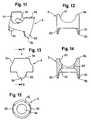
- the lugs 63have an approximate V-shape seen in the side view, as for example shown in Fig. 13 , wherein the corners are rounded and the bottom is straight.
- the shape of the lugsis not restricted to the shape shown in the embodiment. For example, it can be rectangular or U-shaped or otherwise shaped.
- the lugs 63are arranged at 90° with respect to the channel axis formed by the cylindrical recess.
- the depth of the spherical recess 62is such that the lugs 63 extend beyond the area with the greatest outer diameter E of the spherical head 3 when the pressure element is mounted onto the head 3.
- the size of the spherical recess 62 with respect to the spherical head 3is such that the head 3 has a slight oversize with respect to the spherical recess 62 such that when the spherical head 3 is inserted into the spherical recess 62 an interference fit is achieved that holds the head by frictional forces exerted by the lugs 63 onto the head.
- the strength of the frictional forcescan be adjusted by designing an appropriate interference fit between the head and the spherical recess 62 with the lugs 63.
- the pressure element 6has a coaxial bore 64 for allowing access to the screw head 3 with a tool (not shown).
- All parts of the bone anchoring deviceare made of a body-compatible material, such as a body-compatible metal, for example, titanium, body-compatible metal alloys such as, for example, Nitinol or from a body-compatible plastic material, such as, for example, polyetheretherketone (PEEK) or combinations thereof.
- a body-compatible materialsuch as a body-compatible metal, for example, titanium, body-compatible metal alloys such as, for example, Nitinol or from a body-compatible plastic material, such as, for example, polyetheretherketone (PEEK) or combinations thereof.
- PEEKpolyetheretherketone
- the head 3 of the bone anchoring deviceis introduced into the spherical recess 62 of the pressure element 6. Since the head 3 has a slightly greater diameter than the diameter of the spherical recess 62 the head 3 is held by an interference fit within the spherical recess 62 as shown in Fig. 16b ). Thereby, the lugs 63 extend around the head beyond the region with the largest diameter E. In this condition, the head can be pivoted with respect to the pressure element 6 by applying a force to overcome the friction force between the head and the lugs 63.
- the screw element 1 with the mounted pressure elementis introduced into the receiving part 5 from the top end 5a.
- the pressure element 6is oriented such that its cylindrical recess 61 is aligned with the U-shaped recess 53 of the receiving part. Therefore, the lugs 63 are oriented such that they can engage the recesses 55 of the receiving part as previously shown in Fig. 7 .
- the head 3is inserted into the seat portion 52a by overcoming the force inserted through the interference fit between the upper cylindrical edge 52a of the seat portion and the head 3.
- the head 3 with the pressure element 6When the head 3 with the pressure element 6 is mounted within the receiving part 5, the head 3 is held by the friction forces exerted by the lugs 63 onto the head. Further, since the head 3 is held in the seat portion 52 by the cylindrical upper edge 52a of the seat portion, the head is temporarily held in the receiving part in an adjustable angular position. No additional fixation of the pressure element, such as crimping, is necessary since the pressure element is secured against rotation by the engagement of the lugs 63 in the recesses 55 and against escape through the open top end by the interference fit with the head which itself is held by the upper edge 52a in the seat portion.
- the bone anchoring devicemay be delivered in a pre-assembled condition as shown in Fig. 16d ). Usually, several bone anchoring devices are necessary.
- the screw membersare then screwed into the bone or a vertebra and then the receiving parts are aligned to have the correct orientation for the insertion of the rod 100. Since the head is temporarily clamped, for pivoting the receiving parts it is necessary to apply a force to overcome the clamping force until each receiving part has the correct orientation.
- the rod, that connects the bone anchoring devicesis inserted and the inner screw 7 is tightened to move the pressure element downwards to lock the head so that the angular position of the screw member with respect to the receiving part is fixed.
- the rodis simultaneously fixed by the inner screw.
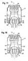
- a second embodiment of the polyaxial bone anchoring deviceis shown in Fig. 17 . All parts that are the same as that of the previous embodiments are indicated with the same reference numerals and the description thereof is not repeated.
- the polyaxial anchoring device according to the second embodimentdiffers from the bone anchoring device according to the first embodiment in that the cylindrical edge 52a of the seat portion 52 may be not present.
- the receiving parthas two recesses 56 in its inner wall that are offset from each other by 180° and oriented in the direction of the channel axis L. The location of the recesses is at a position nearer to the second end 5b than the greatest diameter E of the head 3 when the head 3 is inserted into the seat portion 52.
- the pressure elementcomprises two additional lugs 63 that extend beyond the region with the greatest diameter E of the head and are oriented 90° each with respect to the lugs 63.
- Each of the lugs 63has an outwardly extending nose 65.
- the nose 65snaps into the recesses 56 when the screw member with the pressure element is inserted into the receiving part and provides an additional form fit connection between the receiving part and the pressure element.
- the recesseshave such a height with respect to an axial direction that a further downward movement of the pressure element to lock the head 3 is possible.
- a third embodiment of the polyaxial bone anchoring deviceis shown in Fig. 18 .
- the polyaxial bone anchoring device according to the third embodimentdiffers from the bone anchoring device according to the second embodiment that instead of the recesses 56 and the noses 65 the lugs 63 have slightly outwardly extending flaps 66 that extend more outwardly than the inner diameter of the receiving part allows. When the head with the pressure element is inserted the flaps 66 press against the inner wall of the receiving part and additionally hold the head through a force-fit connection.
- the head 3is not held in the seat portion by an edge or by noses or flaps.
- the pressure elementis held by crimping within the receiving part.
- modificationsinclude more than two lugs or other shapes of the lugs as described with respect to the first embodiment.
- the lugs according to the first embodimentcan be provided at other places than perpendicular to the channel axis.
- the additional lugs and the noses of the second embodiment or the flaps of the third embodimentcan be provided at other places or in other numbers.
- the seat portionmay have another shape than a spherical shape.
- itcan be tapered. All shapes that allow pivoting of the head like a ball and socket joint are possible. Also the head and the head contacting surface needs not to be spherical. It can be otherwise curved.
- anchoring elementall kinds of anchoring elements can be used and combined with a receiving part.
- These anchoring elementare e.g. screws of different lengths, with different diameters, cannulated screws, screws with different thread forms, nails, etc.
- the head and the shaftcan be separate parts that are connectable to each other.
- receiving partscan be used in particular such with different locking devices.
- the one-part locking devicesuch as the inner screw which locks the rod and the head simultaneously
- a two-part locking device with an outer screw and an inner screwcan be used instead of the one-part locking device.
- the pressure elementhas a U-shaped recess with legs extending above the rod.
- the head and the rodcan be fixed independently.
- outer nuts, outer caps, bayonet locking devices or othersare also possible.
- the shape of the receiving partis not limited to the embodiment shown.
- the receiving partcan have an asymmetric end portion for allowing a greater pivot angle of the screw member to a particular side.
- the receiving partis configured to allow the introduction of the screw element from the bottom end.
Landscapes
- Health & Medical Sciences (AREA)
- Orthopedic Medicine & Surgery (AREA)
- Neurology (AREA)
- Life Sciences & Earth Sciences (AREA)
- Engineering & Computer Science (AREA)
- Biomedical Technology (AREA)
- Surgery (AREA)
- General Health & Medical Sciences (AREA)
- Veterinary Medicine (AREA)
- Heart & Thoracic Surgery (AREA)
- Public Health (AREA)
- Animal Behavior & Ethology (AREA)
- Nuclear Medicine, Radiotherapy & Molecular Imaging (AREA)
- Medical Informatics (AREA)
- Molecular Biology (AREA)
- Vascular Medicine (AREA)
- Transplantation (AREA)
- Oral & Maxillofacial Surgery (AREA)
- Cardiology (AREA)
- Surgical Instruments (AREA)
Description
- The invention relates to a polyaxial bone anchoring device for anchoring a stabilization rod in a bone or in a vertebra. The bone anchoring device includes an anchoring element, a receiving part for receiving a head of the bone anchoring element and for receiving a stabilization rod to be connected to the anchoring element. The anchoring element is pivotably connected to the receiving part and can be fixed at an angle by exerting pressure onto the head via a pressure element which is arranged in the receiving part. The pressure element comprises a head contacting surface that contacts the head. The head is slightly oversized with respect to the head contacting surface to achieve an interference fit such that the head is clamped by friction before it is locked.
US 2004/0267264 A1 , from which the preamble of claim 1 derives, describes a polyaxial fixation device wherein the polyaxial bone screw includes an engagement member that is adapted to provide sufficient friction between the spherical head and the receiver member to enable the shank to be maintained in a desired angular orientation before locking the spherical head within the receiver member. The engagement member is realized, for example, by an open snap ring around the head or by spring members provided at the compression cap to frictionally engage the spherical head or by a slot provided in the compression cap.US 2010/0145394 A1 shows a bone fixation assembly including a plurality of bone fixation elements. Each bone anchor is received in an anchor seat, and the anchor seats are joined by a fixation rod so as to operatively couple and fix the position and orientation of the vertebrae relative to each other. The bone anchor is free to rotate relative to the anchor seat, and is also free to pivot in a desired direction relative to the anchor seat.WO 2009/014540 A1 shows a locking mechanism and method of fixation, such as the fixation of a fixation device like a bone screw and of a rod to the spine. The locking mechanism includes a body, an insert, a rod seat and a set screw. The body includes a bottom portion configured to receive the fixation device and the insert but prevents the insert and fixation device from passing therethrough once the insert and fixation device are engaged. The body further includes a side portion configured to receive the rod. Between the rod and the insert is a rod seat.WO 2009/055747 A1 shows a surgical fixation system including a pair of spinal rods, an occipital fixation element, a crosslink connector and a plurality of anchor elements. These elements may be made of a biologically inert material, preferably any metal customarily used for surgical devices, such as for example titanium or stainless steel. It further shows a frictional connection between the head of the anchor element and the seat of the coresponding coupling element.- It is an object of the invention to provide a bone anchoring device which allows an improved handling during surgery while ensuring safe fixation.
- The object is solved by an anchoring device according to claim 1. Further developments are given in the dependent claims.
- With the bone anchoring device a temporary clamping of the head in a desired angular position with respect to the receiving part without locking the head can be achieved. This allows to maintain the receiving part in an adjustable angular position. In this condition, the pressure elements exerts a preload onto the head wherein the head is not locked but prevented from freely pivoting. When the head is temporarily clamped, the alignment of the receiving part with respect to the rod and the insertion of the rod is facilitated, in particular in a situation in which a multitude of bone anchors have to be connected to the rod. When the rod is already inserted into the receiving part, adjustments of the rod are still possible without completely loosening the head.
- The amount of preload exerted onto the head by the pressure member can be exactly predefined by dimensioning the size of the pressure member with respect to the head in view of the interference fit between the pressure member and the head.
- The head may be secured in the seat. This enables an easy assembly of the device without additional crimp tools.
- Further features and advantages of the invention will become apparent from the description of embodiments by means of the accompanying drawings.
- In the drawings:
- Fig. 1
- shows a perspective exploded view of the polyaxial bone anchoring device according to a first embodiment.
- Fig. 2
- shows a perspective view of the bone anchoring device in an assembled state.
- Fig. 3
- shows a cross-sectional view of the polyaxial bone anchoring device in the assembled state, the cross-section being taken in a plane perpendicular to the rod axis.
- Fig. 4
- shows a cross-sectional view of the bone anchoring device along line A-A in
Fig. 3 . - Fig. 5
- shows a cross-sectional view of the bone device in the assembled state, the cross-section taken in a plane including the rod axis.
- Fig. 6
- shows an enlarged view of a portion of
Fig. 5 . - Fig. 7
- shows a perspective view of the receiving part of the polyaxial bone anchoring device.
- Fig. 8
- shows a side view of the receiving part of
Fig. 7 . - Fig. 9
- shows a cross-sectional view of the receiving part, the section being taken in a plane including the rod axis.
- Fig. 10
- shows a cross-sectional view of the receiving part, the section being taken in a plane perpendicular to the rod axis.
- Fig. 11
- shows a perspective view of the pressure element.
- Fig. 12
- shows a side view of the pressure element.
- Fig. 13.
- shows a side view of the pressure element of
Fig. 12 rotated by 90°. - Fig. 14
- shows a cross-sectional view of the pressure element along line B-B in
Fig. 13 . - Fig. 15
- shows a bottom view of the pressure element of
Fig. 11 . - Figs. 16a) to 16d)
- show steps of assembly of the polyaxial bone anchoring device
- Fig. 17
- shows a cross-sectional view of the polyaxial bone anchoring device according to a second embodiment, the section being taken in a plane including the rod axis.
- Fig. 18
- shows a cross-sectional view of the polyaxial bone anchoring device according to a third embodiment, the section being taken along a plane including the rod axis.
- The polyaxial bone anchoring device according to a first embodiment which is generally shown in
Figs. 1 and 2 includes a bone anchoring element 1 in the form of a screw member having a threadedshaft 2 and ahead 3. Thehead 3 is shaped as a spherical segment that has a size including the equator or largest diameter E of the sphere. On its free end thehead 3 has a recess 4 for engagement with a tool. The bone anchoring device further includes a receivingpart 5 for connecting the screw member 1 to arod 100. Apressure element 6 is arranged in the receiving part on top of thehead 3. For securing therod 100 in the receiving part and for exerting pressure onto the head a locking device in the form of an inner screw 7 which cooperates with the receivingpart 5 is provided. - As shown in particular in
Figs. 3 to 10 , the receivingpart 5 is substantially cylindrical and has atop end 5a and abottom end 5b and acoaxial bore 51 extending towards thebottom end 5b. At thebottom end 5b, aseat portion 52 is provided for accommodating thehead 3. Theseat portion 52 is spherically-shaped with a radius corresponding to the radius of thehead 3 and has anopening 52b through which the shaft can extend. It allows thehead 3 to pivot in theseat portion 52 similar to a ball and socket joint. The height of theseat portion 52 is such that theseat portion 52 includes the region of thehead 3 with the largest diameter E, as shown inFig. 6 . - Between the
bore 51 and theseat portion 52 a hollowcylindrical edge portion 52a is provided that has an inner diameter that is smaller than that ofbore 51 and only slightly smaller than the greatest outer diameter E of the head. In other words, thehead 3 has a slight oversize with respect to thecylindrical edge portion 52a to allow the head to be pushed through the edge portion into the seat. Hence, once thehead 3 has been introduced into theseat portion 52 it is held by thecylindrical edge portion 52a within the seat portion. - At the
top end 5a the receiving part has a substantiallyU-shaped recess 53 that forms a channel for receiving therod 100. By means of the U-shaped recess a channel axis L is formed that extends perpendicular to a central axis C of the receivingpart 5. Aninternal thread 54 is provided at the receiving part adjacent thetop end 5a for cooperating with the inner screw 7 of the locking device. - As can be seen particular in
Figs. 7, 9 and 10 , tworecesses 55 that are arranged at 180° offset from each other are provided that extend from thebore 51 to a distance from thebottom end 5b into theseat portion 52. Therecesses 55 are located at 90° with respect to the channel axis L. The shape of therecesses 55 is configured to accommodate a portion of thepressure element 6 to be described below. - The
pressure element 6 is formed in one piece. It is of substantially cylindrical construction and has an outer diameter which allows it to move in the axial direction within thebore 51 of the receivingpart 5. The pressure element has atop end 6a and abottom end 6b. At thetop end 6a acylindrical recess 61 is provided which is configured to receive therod 100 therein. At thebottom end 6b aspherical recess 62 is provided for receiving thehead 3 therein. At thebottom end 6b there are two opposing cut-outs in a circumferential direction by means of which two downwardly extendingopposing lugs 63 are provided, the inner surface of which is spherically shaped and the outer surface of which is cylindrical. Thelugs 63 have an approximate V-shape seen in the side view, as for example shown inFig. 13 , wherein the corners are rounded and the bottom is straight. However, the shape of the lugs is not restricted to the shape shown in the embodiment. For example, it can be rectangular or U-shaped or otherwise shaped. Thelugs 63 are arranged at 90° with respect to the channel axis formed by the cylindrical recess. The depth of thespherical recess 62 is such that thelugs 63 extend beyond the area with the greatest outer diameter E of thespherical head 3 when the pressure element is mounted onto thehead 3. - The size of the
spherical recess 62 with respect to thespherical head 3 is such that thehead 3 has a slight oversize with respect to thespherical recess 62 such that when thespherical head 3 is inserted into thespherical recess 62 an interference fit is achieved that holds the head by frictional forces exerted by thelugs 63 onto the head. The strength of the frictional forces can be adjusted by designing an appropriate interference fit between the head and thespherical recess 62 with thelugs 63. - Furthermore, the
pressure element 6 has acoaxial bore 64 for allowing access to thescrew head 3 with a tool (not shown). - All parts of the bone anchoring device are made of a body-compatible material, such as a body-compatible metal, for example, titanium, body-compatible metal alloys such as, for example, Nitinol or from a body-compatible plastic material, such as, for example, polyetheretherketone (PEEK) or combinations thereof. The parts can be made of the same or of different materials.
- The assembly of the bone anchoring device will now be described with reference to
Figs. 16a) to 16d ). First, as shown inFig. 16a ) thehead 3 of the bone anchoring device is introduced into thespherical recess 62 of thepressure element 6. Since thehead 3 has a slightly greater diameter than the diameter of thespherical recess 62 thehead 3 is held by an interference fit within thespherical recess 62 as shown inFig. 16b ). Thereby, thelugs 63 extend around the head beyond the region with the largest diameter E. In this condition, the head can be pivoted with respect to thepressure element 6 by applying a force to overcome the friction force between the head and thelugs 63. - Then, the screw element 1 with the mounted pressure element is introduced into the receiving
part 5 from thetop end 5a. Thereby, thepressure element 6 is oriented such that itscylindrical recess 61 is aligned with theU-shaped recess 53 of the receiving part. Therefore, thelugs 63 are oriented such that they can engage therecesses 55 of the receiving part as previously shown inFig. 7 . Finally, as shown inFig. 16d ) thehead 3 is inserted into theseat portion 52a by overcoming the force inserted through the interference fit between the uppercylindrical edge 52a of the seat portion and thehead 3. - When the
head 3 with thepressure element 6 is mounted within the receivingpart 5, thehead 3 is held by the friction forces exerted by thelugs 63 onto the head. Further, since thehead 3 is held in theseat portion 52 by the cylindricalupper edge 52a of the seat portion, the head is temporarily held in the receiving part in an adjustable angular position. No additional fixation of the pressure element, such as crimping, is necessary since the pressure element is secured against rotation by the engagement of thelugs 63 in therecesses 55 and against escape through the open top end by the interference fit with the head which itself is held by theupper edge 52a in the seat portion. - In use, the bone anchoring device may be delivered in a pre-assembled condition as shown in
Fig. 16d ). Usually, several bone anchoring devices are necessary. The screw members are then screwed into the bone or a vertebra and then the receiving parts are aligned to have the correct orientation for the insertion of therod 100. Since the head is temporarily clamped, for pivoting the receiving parts it is necessary to apply a force to overcome the clamping force until each receiving part has the correct orientation. When all receiving parts are aligned, the rod, that connects the bone anchoring devices, is inserted and the inner screw 7 is tightened to move the pressure element downwards to lock the head so that the angular position of the screw member with respect to the receiving part is fixed. The rod is simultaneously fixed by the inner screw. - A second embodiment of the polyaxial bone anchoring device is shown in
Fig. 17 . All parts that are the same as that of the previous embodiments are indicated with the same reference numerals and the description thereof is not repeated. The polyaxial anchoring device according to the second embodiment differs from the bone anchoring device according to the first embodiment in that thecylindrical edge 52a of theseat portion 52 may be not present. Instead of the hollowcylindrical edge 52a the receiving part has tworecesses 56 in its inner wall that are offset from each other by 180° and oriented in the direction of the channel axis L. The location of the recesses is at a position nearer to thesecond end 5b than the greatest diameter E of thehead 3 when thehead 3 is inserted into theseat portion 52. - The pressure element comprises two
additional lugs 63 that extend beyond the region with the greatest diameter E of the head and are oriented 90° each with respect to thelugs 63. Each of thelugs 63 has an outwardly extendingnose 65. Thenose 65 snaps into therecesses 56 when the screw member with the pressure element is inserted into the receiving part and provides an additional form fit connection between the receiving part and the pressure element. The recesses have such a height with respect to an axial direction that a further downward movement of the pressure element to lock thehead 3 is possible. - A third embodiment of the polyaxial bone anchoring device is shown in
Fig. 18 . The polyaxial bone anchoring device according to the third embodiment differs from the bone anchoring device according to the second embodiment that instead of therecesses 56 and thenoses 65 thelugs 63 have slightly outwardly extendingflaps 66 that extend more outwardly than the inner diameter of the receiving part allows. When the head with the pressure element is inserted theflaps 66 press against the inner wall of the receiving part and additionally hold the head through a force-fit connection. - Modification of the previously described embodiments are conceivable. In a first modification, the
head 3 is not held in the seat portion by an edge or by noses or flaps. In such a modification, in order to avoid a movement of the head with the pressure element in the direction towards thetop end 5a, the pressure element is held by crimping within the receiving part. - Other modifications include more than two lugs or other shapes of the lugs as described with respect to the first embodiment. In further modifications, the lugs according to the first embodiment can be provided at other places than perpendicular to the channel axis. Also, the additional lugs and the noses of the second embodiment or the flaps of the third embodiment can be provided at other places or in other numbers.
- The seat portion may have another shape than a spherical shape. For example, it can be tapered. All shapes that allow pivoting of the head like a ball and socket joint are possible. Also the head and the head contacting surface needs not to be spherical. It can be otherwise curved.
- For the anchoring element all kinds of anchoring elements can be used and combined with a receiving part. These anchoring element are e.g. screws of different lengths, with different diameters, cannulated screws, screws with different thread forms, nails, etc. The head and the shaft can be separate parts that are connectable to each other.
- Various kinds of receiving parts can be used in particular such with different locking devices. For example, instead of the one-part locking device such as the inner screw which locks the rod and the head simultaneously, a two-part locking device with an outer screw and an inner screw can be used. In this case, the pressure element has a U-shaped recess with legs extending above the rod. With the two-part locking device, the head and the rod can be fixed independently. Further, outer nuts, outer caps, bayonet locking devices or others are also possible. The shape of the receiving part is not limited to the embodiment shown. For example, the receiving part can have an asymmetric end portion for allowing a greater pivot angle of the screw member to a particular side.
- In a further modification, the receiving part is configured to allow the introduction of the screw element from the bottom end.
Claims (14)
- A polyaxial bone anchoring device including
an anchoring element (1) having a shaft (2) for anchoring in the bone and a head (3), the head having a curved outer surface portion having a region with a largest outer diameter (E);
a receiving part (5) having a top end (5a) and a bottom end (5b), a channel (53) for receiving a rod therein, a coaxial bore (51) extending from the top end (5a) in the direction of the bottom end (5b) and a seat portion (52) for receiving the head at the bottom end;
a pressure element (6) arranged within the bore, the pressure element (6) having a head contacting surface portion (62, 63) that contacts the curved outer surface portion of the head (3);
wherein the head (3) is pivotable with respect to the receiving part (5) and can be fixed at an angle by exerting pressure via the pressure element (6) onto the head,
and wherein the head has an oversize in the curved outer surface portion with respect to the head contacting surface portion (62, 63) such that an interference fit is achieved that clamps the head by the friction between the outer surface portion and the head contacting surface portion,characterized in that the seat (52)
has an upper edge (52a) above the region with the largest outer diameter (E) of the head and wherein the head has such an oversize with respect to the upper edge (52a) that the head can be passed through the edge portion (52a) and is prevented from movement towards the top end (5a) once it is in the seat (52). - The polyaxial bone anchoring device of claim 1, wherein the head contacting surface portion (62, 63) contacts the head at least in a region including the largest diameter (E).
- The polyaxial bone anchoring device of claim 1 or 2, wherein the receiving part has a recess (55) at its inner wall that extends into the seat portion (52) to accommodate the head contacting surface portion (63).
- The polyaxial bone anchoring device of one of claims 1 to 3, wherein the head contacting surface portion includes at least two distinct portions (63) clamping the head from opposite sides.
- The polyaxial bone anchoring device of claim 4, wherein the portions are formed as lugs (63).
- The polyaxial bone anchoring device of one of claims 1 to 5, wherein the pressure element (6) is substantially cylindrical with an upper end (6a) and a lower end (6b) and wherein it has a recess (62) at its lower end facing the head by means of which the head contacting surface portion (63) is provided.
- The polyaxial bone anchoring device of one of claims 1 to 6, further configured to hold the head (3) in the seat (52) against movement towards the top end (5a).
- The polyaxial bone anchoring device of one of claims 1 to 7, wherein the head contacting surface portion (62,63) includes a spring element (65) that snaps into a recess (56) provided at the inner wall of the receiving part (5) to prevent movement of the head (3) towards the top end (5a) once it is in the seat portion (52).
- The polyaxial bone anchoring device of one of claims 1 to 8, wherein the head contacting surface portion (64) has a flap (66) with an oversize with respect to the inner wall of the receiving part to achieve an interference fit between the flap (66) and the receiving part (5) that prevents the movement of the head towards the top end (5a).
- The polyaxial bone anchoring device of one of claims 1 to 9, wherein the pressure element has a rod receiving channel (61).
- The polyaxial bone anchoring device of one of claims 1 to 10, wherein the outer surface portion of the head (3) is spherical.
- The polyaxial bone anchoring device of one of claims 1 to 11, wherein the head contacting surface (62, 63) is spherical.
- The polyaxial bone anchoring device of one of claims 1 to 12, wherein the seat portion (52) is spherical.
- The polyaxial bone anchoring device of one of claims 1 to 13, wherein a fixation device (7) is provided that cooperates with the receiving part (5) to lock the head (3) in the seat (52) and to fix the rod (100) in the channel (53).
Priority Applications (11)
| Application Number | Priority Date | Filing Date | Title |
|---|---|---|---|
| EP10197083.8AEP2468199B1 (en) | 2010-12-27 | 2010-12-27 | Polyaxial bone anchoring device |
| EP13177920.9AEP2659845A1 (en) | 2010-12-27 | 2010-12-27 | Polyaxial bone anchoring device |
| ES13179464.6TES2614270T3 (en) | 2010-12-27 | 2010-12-27 | Polyaxial bone anchoring device |
| EP13179464.6AEP2662038B1 (en) | 2010-12-27 | 2010-12-27 | Polyaxial bone anchoring device |
| ES10197083TES2433933T3 (en) | 2010-12-27 | 2010-12-27 | Polyaxial bone anchoring device |
| JP2011279564AJP6071193B2 (en) | 2010-12-27 | 2011-12-21 | Polyaxial bone anchoring device |
| CN201110431521.9ACN102525622B (en) | 2010-12-27 | 2011-12-21 | Polyaxial bone anchoring device |
| TW100147588ATW201228631A (en) | 2010-12-27 | 2011-12-21 | Polyaxial bone anchoring device |
| KR1020110139132AKR20120074219A (en) | 2010-12-27 | 2011-12-21 | Polyaxial bone anchoring device |
| US13/338,188US9333011B2 (en) | 2010-12-27 | 2011-12-27 | Polyaxial bone anchoring device |
| US13/618,000US9585698B2 (en) | 2010-12-27 | 2012-09-14 | Polyaxial bone anchoring device |
Applications Claiming Priority (1)
| Application Number | Priority Date | Filing Date | Title |
|---|---|---|---|
| EP10197083.8AEP2468199B1 (en) | 2010-12-27 | 2010-12-27 | Polyaxial bone anchoring device |
Related Child Applications (1)
| Application Number | Title | Priority Date | Filing Date |
|---|---|---|---|
| EP13179464.6ADivisionEP2662038B1 (en) | 2010-12-27 | 2010-12-27 | Polyaxial bone anchoring device |
Publications (2)
| Publication Number | Publication Date |
|---|---|
| EP2468199A1 EP2468199A1 (en) | 2012-06-27 |
| EP2468199B1true EP2468199B1 (en) | 2013-08-07 |
Family
ID=44017758
Family Applications (3)
| Application Number | Title | Priority Date | Filing Date |
|---|---|---|---|
| EP13177920.9AWithdrawnEP2659845A1 (en) | 2010-12-27 | 2010-12-27 | Polyaxial bone anchoring device |
| EP10197083.8AActiveEP2468199B1 (en) | 2010-12-27 | 2010-12-27 | Polyaxial bone anchoring device |
| EP13179464.6AActiveEP2662038B1 (en) | 2010-12-27 | 2010-12-27 | Polyaxial bone anchoring device |
Family Applications Before (1)
| Application Number | Title | Priority Date | Filing Date |
|---|---|---|---|
| EP13177920.9AWithdrawnEP2659845A1 (en) | 2010-12-27 | 2010-12-27 | Polyaxial bone anchoring device |
Family Applications After (1)
| Application Number | Title | Priority Date | Filing Date |
|---|---|---|---|
| EP13179464.6AActiveEP2662038B1 (en) | 2010-12-27 | 2010-12-27 | Polyaxial bone anchoring device |
Country Status (7)
| Country | Link |
|---|---|
| US (2) | US9333011B2 (en) |
| EP (3) | EP2659845A1 (en) |
| JP (1) | JP6071193B2 (en) |
| KR (1) | KR20120074219A (en) |
| CN (1) | CN102525622B (en) |
| ES (2) | ES2433933T3 (en) |
| TW (1) | TW201228631A (en) |
Families Citing this family (26)
| Publication number | Priority date | Publication date | Assignee | Title |
|---|---|---|---|---|
| US9980753B2 (en) | 2009-06-15 | 2018-05-29 | Roger P Jackson | pivotal anchor with snap-in-place insert having rotation blocking extensions |
| US8444681B2 (en) | 2009-06-15 | 2013-05-21 | Roger P. Jackson | Polyaxial bone anchor with pop-on shank, friction fit retainer and winged insert |
| US8979904B2 (en) | 2007-05-01 | 2015-03-17 | Roger P Jackson | Connecting member with tensioned cord, low profile rigid sleeve and spacer with torsion control |
| US8007522B2 (en) | 2008-02-04 | 2011-08-30 | Depuy Spine, Inc. | Methods for correction of spinal deformities |
| CN103826560A (en) | 2009-06-15 | 2014-05-28 | 罗杰.P.杰克逊 | Polyaxial Bone Anchor with Socket Stem and Winged Inserts with Friction Fit Compression Collars |
| US9345519B1 (en)* | 2010-07-02 | 2016-05-24 | Presidio Surgical, Inc. | Pedicle screw |
| EP2606841B1 (en)* | 2011-12-23 | 2016-03-09 | Biedermann Technologies GmbH & Co. KG | Polyaxial bone anchoring device |
| US9782204B2 (en) | 2012-09-28 | 2017-10-10 | Medos International Sarl | Bone anchor assemblies |
| US9271761B2 (en) | 2012-12-11 | 2016-03-01 | Zimmer Spine | Bone anchoring device |
| EP2764840B1 (en)* | 2013-02-11 | 2017-05-03 | Biedermann Technologies GmbH & Co. KG | Coupling assembly for coupling a rod to a bone anchoring element and bone anchoring device with such a coupling assembly |
| US20140277153A1 (en) | 2013-03-14 | 2014-09-18 | DePuy Synthes Products, LLC | Bone Anchor Assemblies and Methods With Improved Locking |
| US9775660B2 (en) | 2013-03-14 | 2017-10-03 | DePuy Synthes Products, Inc. | Bottom-loading bone anchor assemblies and methods |
| US9724145B2 (en) | 2013-03-14 | 2017-08-08 | Medos International Sarl | Bone anchor assemblies with multiple component bottom loading bone anchors |
| US9259247B2 (en) | 2013-03-14 | 2016-02-16 | Medos International Sarl | Locking compression members for use with bone anchor assemblies and methods |
| US10342582B2 (en) | 2013-03-14 | 2019-07-09 | DePuy Synthes Products, Inc. | Bone anchor assemblies and methods with improved locking |
| ES2611014T3 (en) | 2014-01-13 | 2017-05-04 | Biedermann Technologies Gmbh & Co. Kg | Coupling assembly for coupling a rod to a bone anchoring element, and polyaxial bone anchoring device |
| CN108697445B (en) | 2016-02-26 | 2022-04-19 | 美多斯国际有限公司 | Polyaxial bone fixation element |
| US9962192B2 (en) | 2016-03-17 | 2018-05-08 | Medos International Sarl | Multipoint fixation implants |
| US11026730B2 (en) | 2017-05-10 | 2021-06-08 | Medos International Sarl | Bone anchors with drag features and related methods |
| US10898232B2 (en) | 2018-03-20 | 2021-01-26 | Medos International Sàrl | Multipoint fixation implants and related methods |
| US11571244B2 (en) | 2019-05-22 | 2023-02-07 | Nuvasive, Inc. | Posterior spinal fixation screws |
| EP4103083B1 (en) | 2020-02-14 | 2024-10-23 | Medos International Sàrl | Integrated multipoint fixation screw |
| USD956233S1 (en)* | 2020-04-24 | 2022-06-28 | Solco Biomedical Co., Ltd. | Cervical screw |
| CN111973324B (en)* | 2020-08-20 | 2022-11-11 | 四川大学华西医院 | Orthopedic implant system based on stress adaptive and controllable adjustment and its control method |
| US12364515B2 (en) | 2021-03-05 | 2025-07-22 | Medos International Sàrl | Multi-feature polyaxial screw |
| WO2022184797A1 (en) | 2021-03-05 | 2022-09-09 | Medos International Sarl | Selectively locking polyaxial screw |
Family Cites Families (33)
| Publication number | Priority date | Publication date | Assignee | Title |
|---|---|---|---|---|
| DE19507141B4 (en) | 1995-03-01 | 2004-12-23 | Harms, Jürgen, Prof. Dr.med. | Locking |
| US5879350A (en) | 1996-09-24 | 1999-03-09 | Sdgi Holdings, Inc. | Multi-axial bone screw assembly |
| US6010503A (en) | 1998-04-03 | 2000-01-04 | Spinal Innovations, Llc | Locking mechanism |
| US6113601A (en) | 1998-06-12 | 2000-09-05 | Bones Consulting, Llc | Polyaxial pedicle screw having a loosely coupled locking cap |
| DE19936286C2 (en) | 1999-08-02 | 2002-01-17 | Lutz Biedermann | bone screw |
| US6488681B2 (en) | 2001-01-05 | 2002-12-03 | Stryker Spine S.A. | Pedicle screw assembly |
| US8353932B2 (en) | 2005-09-30 | 2013-01-15 | Jackson Roger P | Polyaxial bone anchor assembly with one-piece closure, pressure insert and plastic elongate member |
| US6837889B2 (en) | 2002-03-01 | 2005-01-04 | Endius Incorporated | Apparatus for connecting a longitudinal member to a bone portion |
| US7066937B2 (en) | 2002-02-13 | 2006-06-27 | Endius Incorporated | Apparatus for connecting a longitudinal member to a bone portion |
| US7087057B2 (en)* | 2003-06-27 | 2006-08-08 | Depuy Acromed, Inc. | Polyaxial bone screw |
| WO2005065397A2 (en) | 2003-12-30 | 2005-07-21 | Depuy Spine Sarl | Bone anchor assemblies |
| US7604655B2 (en) | 2004-10-25 | 2009-10-20 | X-Spine Systems, Inc. | Bone fixation system and method for using the same |
| US10076361B2 (en) | 2005-02-22 | 2018-09-18 | Roger P. Jackson | Polyaxial bone screw with spherical capture, compression and alignment and retention structures |
| US7811310B2 (en) | 2005-05-04 | 2010-10-12 | Spinefrontier, Inc | Multistage spinal fixation locking mechanism |
| WO2007041702A2 (en) | 2005-10-04 | 2007-04-12 | Alphaspine, Inc. | Pedicle screw system with provisional locking aspects |
| ES2313182T3 (en)* | 2005-10-12 | 2009-03-01 | Biedermann Motech Gmbh | PIVOTABLE POLIAXIAL STORM IN A SINGLE FLAT. |
| US20070118117A1 (en) | 2005-10-20 | 2007-05-24 | Ebi, L.P. | Bone fixation assembly |
| WO2008008511A2 (en) | 2006-07-14 | 2008-01-17 | Laszlo Garamszegi | Pedicle screw assembly with inclined surface seat |
| WO2008118295A2 (en) | 2007-03-26 | 2008-10-02 | Laszlo Garamszegi | Bottom-loading pedicle screw assembly |
| US20100160980A1 (en)* | 2007-07-26 | 2010-06-24 | Biotechni America Spine Group, Inc. | Spinal fixation assembly |
| ES2348814T3 (en) | 2007-07-31 | 2010-12-15 | Biedermann Motech Gmbh | ANCHORAGE DEVICE Ã “SEO. |
| DE102007042953B4 (en)* | 2007-08-30 | 2015-01-22 | Aesculap Ag | Orthopedic retention system |
| EP2211742A4 (en)* | 2007-10-24 | 2012-12-19 | Nuvasive Inc | Surgical fixation system and related methods |
| CA2742399A1 (en)* | 2008-11-03 | 2010-06-03 | Dustin M. Harvey | Uni-planar bone fixation assembly |
| ES2378588T3 (en) | 2008-12-30 | 2012-04-16 | Biedermann Motech Gmbh | Receiving part for receiving a rod for coupling the rod in a bone anchoring element and bone anchoring device with such receiving part |
| ES2548580T3 (en)* | 2009-02-20 | 2015-10-19 | Biedermann Technologies Gmbh & Co. Kg | Receiving part for housing a rod for coupling to a bone anchoring element and bone anchoring device that includes such receiving part |
| EP2548525B1 (en) | 2009-09-25 | 2014-04-02 | Biedermann Technologies GmbH & Co. KG | Bone anchoring device |
| ES2525046T3 (en) | 2009-12-21 | 2014-12-16 | Biedermann Technologies Gmbh & Co. Kg | Bone anchoring device |
| EP2606842B1 (en) | 2010-03-29 | 2018-08-29 | Biedermann Technologies GmbH & Co. KG | Bone anchoring device |
| EP3047812B1 (en) | 2010-11-22 | 2020-01-01 | Biedermann Technologies GmbH & Co. KG | Polyaxial bone anchoring device |
| US9044274B2 (en)* | 2010-12-01 | 2015-06-02 | Amendia, Inc. | Bone screw system |
| ES2461843T3 (en) | 2010-12-23 | 2014-05-21 | Biedermann Technologies Gmbh & Co. Kg | Bone anchoring device |
| EP2606841B1 (en) | 2011-12-23 | 2016-03-09 | Biedermann Technologies GmbH & Co. KG | Polyaxial bone anchoring device |
- 2010
- 2010-12-27EPEP13177920.9Apatent/EP2659845A1/ennot_activeWithdrawn
- 2010-12-27ESES10197083Tpatent/ES2433933T3/enactiveActive
- 2010-12-27EPEP10197083.8Apatent/EP2468199B1/enactiveActive
- 2010-12-27ESES13179464.6Tpatent/ES2614270T3/enactiveActive
- 2010-12-27EPEP13179464.6Apatent/EP2662038B1/enactiveActive
- 2011
- 2011-12-21TWTW100147588Apatent/TW201228631A/enunknown
- 2011-12-21KRKR1020110139132Apatent/KR20120074219A/ennot_activeCeased
- 2011-12-21CNCN201110431521.9Apatent/CN102525622B/ennot_activeExpired - Fee Related
- 2011-12-21JPJP2011279564Apatent/JP6071193B2/ennot_activeExpired - Fee Related
- 2011-12-27USUS13/338,188patent/US9333011B2/enactiveActive
- 2012
- 2012-09-14USUS13/618,000patent/US9585698B2/enactiveActive
Also Published As
| Publication number | Publication date |
|---|---|
| JP2012135618A (en) | 2012-07-19 |
| US20130066376A1 (en) | 2013-03-14 |
| EP2468199A1 (en) | 2012-06-27 |
| ES2614270T3 (en) | 2017-05-30 |
| KR20120074219A (en) | 2012-07-05 |
| US20120165882A1 (en) | 2012-06-28 |
| TW201228631A (en) | 2012-07-16 |
| EP2659845A1 (en) | 2013-11-06 |
| US9333011B2 (en) | 2016-05-10 |
| CN102525622A (en) | 2012-07-04 |
| JP6071193B2 (en) | 2017-02-01 |
| ES2433933T3 (en) | 2013-12-13 |
| EP2662038B1 (en) | 2016-10-19 |
| EP2662038A1 (en) | 2013-11-13 |
| CN102525622B (en) | 2016-04-20 |
| US9585698B2 (en) | 2017-03-07 |
Similar Documents
| Publication | Publication Date | Title |
|---|---|---|
| EP2468199B1 (en) | Polyaxial bone anchoring device | |
| US20220031368A1 (en) | Bone anchoring device | |
| US9924974B2 (en) | Polyaxial bone anchoring device | |
| US20220031369A1 (en) | Polyaxial bone anchoring device with enlarged pivot angle | |
| US9247965B2 (en) | Polyaxial bone anchoring device with enlarged pivot angle | |
| US9277938B2 (en) | Polyaxial bone anchoring system | |
| EP2837347B1 (en) | Bone anchoring device | |
| EP3047812B1 (en) | Polyaxial bone anchoring device | |
| EP2335625B1 (en) | Bone anchoring device | |
| US9192417B2 (en) | Monoplanar bone anchoring device with selectable pivot plane | |
| US20130110178A1 (en) | High angulation polyaxial bone anchoring device | |
| EP2674123A1 (en) | Polyaxial bone anchoring device |
Legal Events
| Date | Code | Title | Description |
|---|---|---|---|
| AK | Designated contracting states | Kind code of ref document:A1 Designated state(s):AL AT BE BG CH CY CZ DE DK EE ES FI FR GB GR HR HU IE IS IT LI LT LU LV MC MK MT NL NO PL PT RO RS SE SI SK SM TR | |
| AX | Request for extension of the european patent | Extension state:BA ME | |
| PUAI | Public reference made under article 153(3) epc to a published international application that has entered the european phase | Free format text:ORIGINAL CODE: 0009012 | |
| 17P | Request for examination filed | Effective date:20121112 | |
| GRAP | Despatch of communication of intention to grant a patent | Free format text:ORIGINAL CODE: EPIDOSNIGR1 | |
| GRAS | Grant fee paid | Free format text:ORIGINAL CODE: EPIDOSNIGR3 | |
| GRAA | (expected) grant | Free format text:ORIGINAL CODE: 0009210 | |
| AK | Designated contracting states | Kind code of ref document:B1 Designated state(s):AL AT BE BG CH CY CZ DE DK EE ES FI FR GB GR HR HU IE IS IT LI LT LU LV MC MK MT NL NO PL PT RO RS SE SI SK SM TR | |
| REG | Reference to a national code | Ref country code:GB Ref legal event code:FG4D | |
| REG | Reference to a national code | Ref country code:CH Ref legal event code:NV Representative=s name:NOVAGRAAF INTERNATIONAL SA, CH Ref country code:CH Ref legal event code:EP Ref country code:AT Ref legal event code:REF Ref document number:625373 Country of ref document:AT Kind code of ref document:T Effective date:20130815 | |
| REG | Reference to a national code | Ref country code:IE Ref legal event code:FG4D | |
| REG | Reference to a national code | Ref country code:DE Ref legal event code:R096 Ref document number:602010009173 Country of ref document:DE Effective date:20131002 | |
| REG | Reference to a national code | Ref country code:ES Ref legal event code:FG2A Ref document number:2433933 Country of ref document:ES Kind code of ref document:T3 Effective date:20131213 | |
| REG | Reference to a national code | Ref country code:AT Ref legal event code:MK05 Ref document number:625373 Country of ref document:AT Kind code of ref document:T Effective date:20130807 | |
| REG | Reference to a national code | Ref country code:NL Ref legal event code:VDEP Effective date:20130807 | |
| REG | Reference to a national code | Ref country code:LT Ref legal event code:MG4D | |
| PG25 | Lapsed in a contracting state [announced via postgrant information from national office to epo] | Ref country code:PT Free format text:LAPSE BECAUSE OF FAILURE TO SUBMIT A TRANSLATION OF THE DESCRIPTION OR TO PAY THE FEE WITHIN THE PRESCRIBED TIME-LIMIT Effective date:20131209 Ref country code:LT Free format text:LAPSE BECAUSE OF FAILURE TO SUBMIT A TRANSLATION OF THE DESCRIPTION OR TO PAY THE FEE WITHIN THE PRESCRIBED TIME-LIMIT Effective date:20130807 Ref country code:IS Free format text:LAPSE BECAUSE OF FAILURE TO SUBMIT A TRANSLATION OF THE DESCRIPTION OR TO PAY THE FEE WITHIN THE PRESCRIBED TIME-LIMIT Effective date:20131207 Ref country code:AT Free format text:LAPSE BECAUSE OF FAILURE TO SUBMIT A TRANSLATION OF THE DESCRIPTION OR TO PAY THE FEE WITHIN THE PRESCRIBED TIME-LIMIT Effective date:20130807 Ref country code:NO Free format text:LAPSE BECAUSE OF FAILURE TO SUBMIT A TRANSLATION OF THE DESCRIPTION OR TO PAY THE FEE WITHIN THE PRESCRIBED TIME-LIMIT Effective date:20131107 Ref country code:CY Free format text:LAPSE BECAUSE OF FAILURE TO SUBMIT A TRANSLATION OF THE DESCRIPTION OR TO PAY THE FEE WITHIN THE PRESCRIBED TIME-LIMIT Effective date:20130828 Ref country code:SE Free format text:LAPSE BECAUSE OF FAILURE TO SUBMIT A TRANSLATION OF THE DESCRIPTION OR TO PAY THE FEE WITHIN THE PRESCRIBED TIME-LIMIT Effective date:20130807 Ref country code:HR Free format text:LAPSE BECAUSE OF FAILURE TO SUBMIT A TRANSLATION OF THE DESCRIPTION OR TO PAY THE FEE WITHIN THE PRESCRIBED TIME-LIMIT Effective date:20130807 | |
| PG25 | Lapsed in a contracting state [announced via postgrant information from national office to epo] | Ref country code:NL Free format text:LAPSE BECAUSE OF FAILURE TO SUBMIT A TRANSLATION OF THE DESCRIPTION OR TO PAY THE FEE WITHIN THE PRESCRIBED TIME-LIMIT Effective date:20130807 Ref country code:GR Free format text:LAPSE BECAUSE OF FAILURE TO SUBMIT A TRANSLATION OF THE DESCRIPTION OR TO PAY THE FEE WITHIN THE PRESCRIBED TIME-LIMIT Effective date:20131108 Ref country code:BE Free format text:LAPSE BECAUSE OF FAILURE TO SUBMIT A TRANSLATION OF THE DESCRIPTION OR TO PAY THE FEE WITHIN THE PRESCRIBED TIME-LIMIT Effective date:20130807 Ref country code:PL Free format text:LAPSE BECAUSE OF FAILURE TO SUBMIT A TRANSLATION OF THE DESCRIPTION OR TO PAY THE FEE WITHIN THE PRESCRIBED TIME-LIMIT Effective date:20130807 Ref country code:FI Free format text:LAPSE BECAUSE OF FAILURE TO SUBMIT A TRANSLATION OF THE DESCRIPTION OR TO PAY THE FEE WITHIN THE PRESCRIBED TIME-LIMIT Effective date:20130807 Ref country code:LV Free format text:LAPSE BECAUSE OF FAILURE TO SUBMIT A TRANSLATION OF THE DESCRIPTION OR TO PAY THE FEE WITHIN THE PRESCRIBED TIME-LIMIT Effective date:20130807 Ref country code:SI Free format text:LAPSE BECAUSE OF FAILURE TO SUBMIT A TRANSLATION OF THE DESCRIPTION OR TO PAY THE FEE WITHIN THE PRESCRIBED TIME-LIMIT Effective date:20130807 | |
| PG25 | Lapsed in a contracting state [announced via postgrant information from national office to epo] | Ref country code:CY Free format text:LAPSE BECAUSE OF FAILURE TO SUBMIT A TRANSLATION OF THE DESCRIPTION OR TO PAY THE FEE WITHIN THE PRESCRIBED TIME-LIMIT Effective date:20130807 | |
| PG25 | Lapsed in a contracting state [announced via postgrant information from national office to epo] | Ref country code:CZ Free format text:LAPSE BECAUSE OF FAILURE TO SUBMIT A TRANSLATION OF THE DESCRIPTION OR TO PAY THE FEE WITHIN THE PRESCRIBED TIME-LIMIT Effective date:20130807 Ref country code:DK Free format text:LAPSE BECAUSE OF FAILURE TO SUBMIT A TRANSLATION OF THE DESCRIPTION OR TO PAY THE FEE WITHIN THE PRESCRIBED TIME-LIMIT Effective date:20130807 Ref country code:EE Free format text:LAPSE BECAUSE OF FAILURE TO SUBMIT A TRANSLATION OF THE DESCRIPTION OR TO PAY THE FEE WITHIN THE PRESCRIBED TIME-LIMIT Effective date:20130807 Ref country code:SK Free format text:LAPSE BECAUSE OF FAILURE TO SUBMIT A TRANSLATION OF THE DESCRIPTION OR TO PAY THE FEE WITHIN THE PRESCRIBED TIME-LIMIT Effective date:20130807 Ref country code:RO Free format text:LAPSE BECAUSE OF FAILURE TO SUBMIT A TRANSLATION OF THE DESCRIPTION OR TO PAY THE FEE WITHIN THE PRESCRIBED TIME-LIMIT Effective date:20130807 | |
| PLBE | No opposition filed within time limit | Free format text:ORIGINAL CODE: 0009261 | |
| STAA | Information on the status of an ep patent application or granted ep patent | Free format text:STATUS: NO OPPOSITION FILED WITHIN TIME LIMIT | |
| 26N | No opposition filed | Effective date:20140508 | |
| REG | Reference to a national code | Ref country code:DE Ref legal event code:R097 Ref document number:602010009173 Country of ref document:DE Effective date:20140508 | |
| PG25 | Lapsed in a contracting state [announced via postgrant information from national office to epo] | Ref country code:LU Free format text:LAPSE BECAUSE OF FAILURE TO SUBMIT A TRANSLATION OF THE DESCRIPTION OR TO PAY THE FEE WITHIN THE PRESCRIBED TIME-LIMIT Effective date:20131227 | |
| REG | Reference to a national code | Ref country code:IE Ref legal event code:MM4A | |
| PG25 | Lapsed in a contracting state [announced via postgrant information from national office to epo] | Ref country code:IE Free format text:LAPSE BECAUSE OF NON-PAYMENT OF DUE FEES Effective date:20131227 | |
| PG25 | Lapsed in a contracting state [announced via postgrant information from national office to epo] | Ref country code:MC Free format text:LAPSE BECAUSE OF FAILURE TO SUBMIT A TRANSLATION OF THE DESCRIPTION OR TO PAY THE FEE WITHIN THE PRESCRIBED TIME-LIMIT Effective date:20130807 | |
| PG25 | Lapsed in a contracting state [announced via postgrant information from national office to epo] | Ref country code:SM Free format text:LAPSE BECAUSE OF FAILURE TO SUBMIT A TRANSLATION OF THE DESCRIPTION OR TO PAY THE FEE WITHIN THE PRESCRIBED TIME-LIMIT Effective date:20130807 | |
| PG25 | Lapsed in a contracting state [announced via postgrant information from national office to epo] | Ref country code:TR Free format text:LAPSE BECAUSE OF FAILURE TO SUBMIT A TRANSLATION OF THE DESCRIPTION OR TO PAY THE FEE WITHIN THE PRESCRIBED TIME-LIMIT Effective date:20130807 | |
| PG25 | Lapsed in a contracting state [announced via postgrant information from national office to epo] | Ref country code:MK Free format text:LAPSE BECAUSE OF FAILURE TO SUBMIT A TRANSLATION OF THE DESCRIPTION OR TO PAY THE FEE WITHIN THE PRESCRIBED TIME-LIMIT Effective date:20130807 Ref country code:BG Free format text:LAPSE BECAUSE OF FAILURE TO SUBMIT A TRANSLATION OF THE DESCRIPTION OR TO PAY THE FEE WITHIN THE PRESCRIBED TIME-LIMIT Effective date:20130807 Ref country code:RS Free format text:LAPSE BECAUSE OF FAILURE TO SUBMIT A TRANSLATION OF THE DESCRIPTION OR TO PAY THE FEE WITHIN THE PRESCRIBED TIME-LIMIT Effective date:20131107 Ref country code:HU Free format text:LAPSE BECAUSE OF FAILURE TO SUBMIT A TRANSLATION OF THE DESCRIPTION OR TO PAY THE FEE WITHIN THE PRESCRIBED TIME-LIMIT; INVALID AB INITIO Effective date:20101227 | |
| PG25 | Lapsed in a contracting state [announced via postgrant information from national office to epo] | Ref country code:MT Free format text:LAPSE BECAUSE OF FAILURE TO SUBMIT A TRANSLATION OF THE DESCRIPTION OR TO PAY THE FEE WITHIN THE PRESCRIBED TIME-LIMIT Effective date:20130807 | |
| REG | Reference to a national code | Ref country code:FR Ref legal event code:PLFP Year of fee payment:6 | |
| REG | Reference to a national code | Ref country code:FR Ref legal event code:PLFP Year of fee payment:7 | |
| PGFP | Annual fee paid to national office [announced via postgrant information from national office to epo] | Ref country code:FR Payment date:20161221 Year of fee payment:7 Ref country code:ES Payment date:20161221 Year of fee payment:7 | |
| PGFP | Annual fee paid to national office [announced via postgrant information from national office to epo] | Ref country code:IT Payment date:20161229 Year of fee payment:7 | |
| REG | Reference to a national code | Ref country code:FR Ref legal event code:ST Effective date:20180831 | |
| PG25 | Lapsed in a contracting state [announced via postgrant information from national office to epo] | Ref country code:FR Free format text:LAPSE BECAUSE OF NON-PAYMENT OF DUE FEES Effective date:20180102 Ref country code:AL Free format text:LAPSE BECAUSE OF FAILURE TO SUBMIT A TRANSLATION OF THE DESCRIPTION OR TO PAY THE FEE WITHIN THE PRESCRIBED TIME-LIMIT Effective date:20130807 Ref country code:IT Free format text:LAPSE BECAUSE OF NON-PAYMENT OF DUE FEES Effective date:20171227 | |
| REG | Reference to a national code | Ref country code:ES Ref legal event code:FD2A Effective date:20190704 | |
| PG25 | Lapsed in a contracting state [announced via postgrant information from national office to epo] | Ref country code:ES Free format text:LAPSE BECAUSE OF NON-PAYMENT OF DUE FEES Effective date:20171228 | |
| P01 | Opt-out of the competence of the unified patent court (upc) registered | Effective date:20230525 | |
| PGFP | Annual fee paid to national office [announced via postgrant information from national office to epo] | Ref country code:DE Payment date:20241218 Year of fee payment:15 | |
| PGFP | Annual fee paid to national office [announced via postgrant information from national office to epo] | Ref country code:GB Payment date:20241213 Year of fee payment:15 | |
| PGFP | Annual fee paid to national office [announced via postgrant information from national office to epo] | Ref country code:CH Payment date:20250101 Year of fee payment:15 |