EP2468198A1 - Bone anchoring device - Google Patents
Bone anchoring deviceDownload PDFInfo
- Publication number
- EP2468198A1 EP2468198A1EP10196880AEP10196880AEP2468198A1EP 2468198 A1EP2468198 A1EP 2468198A1EP 10196880 AEP10196880 AEP 10196880AEP 10196880 AEP10196880 AEP 10196880AEP 2468198 A1EP2468198 A1EP 2468198A1
- Authority
- EP
- European Patent Office
- Prior art keywords
- head
- bone anchoring
- pressure element
- anchoring device
- pressure
- Prior art date
- Legal status (The legal status is an assumption and is not a legal conclusion. Google has not performed a legal analysis and makes no representation as to the accuracy of the status listed.)
- Granted
Links
- 238000004873anchoringMethods0.000titleclaimsabstractdescription52
- 210000000988bone and boneAnatomy0.000titleclaimsabstractdescription47
- 230000036316preloadEffects0.000claimsabstractdescription6
- 239000002861polymer materialSubstances0.000claimsabstract2
- 239000000463materialSubstances0.000claimsdescription5
- 229920001971elastomerPolymers0.000claimsdescription3
- 239000000806elastomerSubstances0.000claimsdescription3
- 238000001356surgical procedureMethods0.000abstractdescription2
- 238000002788crimpingMethods0.000description3
- -1for exampleSubstances0.000description3
- 238000012986modificationMethods0.000description3
- 230000004048modificationEffects0.000description3
- 239000004696Poly ether ether ketoneSubstances0.000description2
- 239000004699Ultra-high molecular weight polyethyleneSubstances0.000description2
- JUPQTSLXMOCDHR-UHFFFAOYSA-Nbenzene-1,4-diol;bis(4-fluorophenyl)methanoneChemical compoundOC1=CC=C(O)C=C1.C1=CC(F)=CC=C1C(=O)C1=CC=C(F)C=C1JUPQTSLXMOCDHR-UHFFFAOYSA-N0.000description2
- 230000006835compressionEffects0.000description2
- 238000007906compressionMethods0.000description2
- 238000003780insertionMethods0.000description2
- 230000037431insertionEffects0.000description2
- 239000004033plasticSubstances0.000description2
- 229920003023plasticPolymers0.000description2
- 229920002530polyetherether ketonePolymers0.000description2
- 230000006641stabilisationEffects0.000description2
- 238000011105stabilizationMethods0.000description2
- 229920000785ultra high molecular weight polyethylenePolymers0.000description2
- RTAQQCXQSZGOHL-UHFFFAOYSA-NTitaniumChemical compound[Ti]RTAQQCXQSZGOHL-UHFFFAOYSA-N0.000description1
- 230000004308accommodationEffects0.000description1
- 238000010276constructionMethods0.000description1
- 230000001419dependent effectEffects0.000description1
- 238000011161developmentMethods0.000description1
- 230000018109developmental processEffects0.000description1
- 229910052751metalInorganic materials0.000description1
- 239000002184metalSubstances0.000description1
- 229910001092metal group alloyInorganic materials0.000description1
- HLXZNVUGXRDIFK-UHFFFAOYSA-Nnickel titaniumChemical compound[Ti].[Ti].[Ti].[Ti].[Ti].[Ti].[Ti].[Ti].[Ti].[Ti].[Ti].[Ni].[Ni].[Ni].[Ni].[Ni].[Ni].[Ni].[Ni].[Ni].[Ni].[Ni].[Ni].[Ni].[Ni]HLXZNVUGXRDIFK-UHFFFAOYSA-N0.000description1
- 229910001000nickel titaniumInorganic materials0.000description1
- 229910052710siliconInorganic materials0.000description1
- 239000010703siliconSubstances0.000description1
- 239000007787solidSubstances0.000description1
- 239000010936titaniumSubstances0.000description1
- 229910052719titaniumInorganic materials0.000description1
Images


Classifications
- A—HUMAN NECESSITIES
- A61—MEDICAL OR VETERINARY SCIENCE; HYGIENE
- A61B—DIAGNOSIS; SURGERY; IDENTIFICATION
- A61B17/00—Surgical instruments, devices or methods
- A61B17/56—Surgical instruments or methods for treatment of bones or joints; Devices specially adapted therefor
- A61B17/58—Surgical instruments or methods for treatment of bones or joints; Devices specially adapted therefor for osteosynthesis, e.g. bone plates, screws or setting implements
- A61B17/68—Internal fixation devices, including fasteners and spinal fixators, even if a part thereof projects from the skin
- A61B17/84—Fasteners therefor or fasteners being internal fixation devices
- A61B17/86—Pins or screws or threaded wires; nuts therefor
- A—HUMAN NECESSITIES
- A61—MEDICAL OR VETERINARY SCIENCE; HYGIENE
- A61B—DIAGNOSIS; SURGERY; IDENTIFICATION
- A61B17/00—Surgical instruments, devices or methods
- A61B17/56—Surgical instruments or methods for treatment of bones or joints; Devices specially adapted therefor
- A61B17/58—Surgical instruments or methods for treatment of bones or joints; Devices specially adapted therefor for osteosynthesis, e.g. bone plates, screws or setting implements
- A61B17/68—Internal fixation devices, including fasteners and spinal fixators, even if a part thereof projects from the skin
- A61B17/70—Spinal positioners or stabilisers, e.g. stabilisers comprising fluid filler in an implant
- A61B17/7001—Screws or hooks combined with longitudinal elements which do not contact vertebrae
- A61B17/7035—Screws or hooks, wherein a rod-clamping part and a bone-anchoring part can pivot relative to each other
- A61B17/7037—Screws or hooks, wherein a rod-clamping part and a bone-anchoring part can pivot relative to each other wherein pivoting is blocked when the rod is clamped
- A—HUMAN NECESSITIES
- A61—MEDICAL OR VETERINARY SCIENCE; HYGIENE
- A61B—DIAGNOSIS; SURGERY; IDENTIFICATION
- A61B17/00—Surgical instruments, devices or methods
- A61B17/56—Surgical instruments or methods for treatment of bones or joints; Devices specially adapted therefor
- A61B17/58—Surgical instruments or methods for treatment of bones or joints; Devices specially adapted therefor for osteosynthesis, e.g. bone plates, screws or setting implements
- A61B17/68—Internal fixation devices, including fasteners and spinal fixators, even if a part thereof projects from the skin
- A61B17/70—Spinal positioners or stabilisers, e.g. stabilisers comprising fluid filler in an implant
- Y—GENERAL TAGGING OF NEW TECHNOLOGICAL DEVELOPMENTS; GENERAL TAGGING OF CROSS-SECTIONAL TECHNOLOGIES SPANNING OVER SEVERAL SECTIONS OF THE IPC; TECHNICAL SUBJECTS COVERED BY FORMER USPC CROSS-REFERENCE ART COLLECTIONS [XRACs] AND DIGESTS
- Y10—TECHNICAL SUBJECTS COVERED BY FORMER USPC
- Y10T—TECHNICAL SUBJECTS COVERED BY FORMER US CLASSIFICATION
- Y10T29/00—Metal working
- Y10T29/49—Method of mechanical manufacture
- Y10T29/49826—Assembling or joining
Definitions
- the inventionrelates to a bone anchoring device for anchoring a stabilization rod in a bone or in a vertebra.
- the bone anchoring deviceincludes an anchoring element, a receiving part for receiving a head of the bone anchoring element and for receiving a stabilization rod to be connected to the anchoring element.
- the anchoring elementis pivotably connected to the receiving part and can be fixed at an angle by exerting pressure onto the head via a pressure element which is arranged in the receiving part.
- the headcomprises a recess which accommodates a closed ring which is configured to cooperate in such a way with the head and the pressure element that the pressure element can assume a position within the receiving part in which it clamps the head via the ring by friction without locking it.
- US 2004/0267264 Aldescribes a polyaxial fixation device, wherein the polyaxial bone screw includes an engagement member that is adapted to provide sufficient friction between the spherical head and the receiver member to enable the shank to be maintained in a desired angular orientation before locking the spherical head within the receiver member.
- the engagement memberis realized, for example, by an open snap ring around the head or by spring members provided at the compression cap to frictionally engage the spherical head or by a slot provided in the compression cap.
- a temporary clamping of the head in a desired angular position with respect to the receiving part without locking the headcan be achieved.
- Thisallows the receiving part to be held in an adjustable angular position.
- the pressure elementexerts a preload onto the head via the ring in which the head is not locked but frictionally prevented from freely pivoting.
- the headis temporarily clamped the alignment of the receiving part to the rod and the insertion of the rod is facilitated.
- adjustments of the rodare still possible without completely loosening the head within the receiving part.
- the pressure elementcan be pressed onto the head to lock the head in its desired portion.
- the bone anchoring devicehas only few parts which are of simple design.
- the heads of already manufactured bone anchoring devicescan easily be upgraded to the system according to the present invention. Only a groove around the head and a closed ring which is accommodated by the groove have to be provided.
- the parts of the bone anchoring devicecan be manufactured in series at low costs.
- the polyaxial bone anchoring device 1according to a first embodiment as shown in Figs. 1, 2 and 5a includes a bone anchoring element 2 in the form of a screw member 2 having a threaded shaft 3 and a head 4.
- the head 4includes a tool recess 4a at its free end for engagement with a tool (not shown) to insert the threaded shaft 3 into the bone.
- the bone anchoring device 1further includes a receiving part 5 for connecting the screw member 2 to a rod 20.
- a pressure element 6is arranged in the receiving part 5 on top of the head 4.
- a locking devicefor example an inner screw 7, which cooperates with the receiving part 5, is provided.
- the head 4is shaped as spherical segment having a flat free end and having the tool recess 4a at the flat free end.
- An annular groove 41is provided at a position above the greatest diameter in a direction towards the free end.
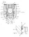
- the cross-section of the annular groove 41is substantially trapezoidal with an open side, as can be seen from Fig. 6a .
- the annular groove 41serves for accommodation of a ring 8.
- the ground of the annular groove 41is substantially coaxial to the axis of the screw member 2.
- the edges on the ground of the annular groove 41can be rounded.
- the free end of the head 4can also differ from the flat form.
- the receiving part 5is a substantially cylindrical one piece part and has a top end 51 and a bottom end 52.
- a passageway extending from the top end 51 to the bottom end 52is formed by a coaxial bore 53 followed by a seat portion 54 for receiving the head 4 of the screw member 2.
- the seat portion 54has an opening 55 at the bottom end 52 through which the shaft 3 of the screw member 2 extends.
- the seat portion 54is shown to be spherically-shaped, but it can be tapered or it can have any other shape that allows to receive the head 4 so that it can pivot with respect to the receiving part 5.
- a substantially U-shaped recess 56is provided by means of which two free legs 57, 58 are formed that are the sidewalls of a channel for receiving the rod 20.
- An internal thread 59is provided at the legs for cooperating with the inner screw 7.
- the receiving part 5further comprises at a distance from the bottom end 52 which is smaller than the distance from the top end 51 two blind holes 500a, 500b forming crimp bores that extend from the outer surface to a distance from the inner wall of the coaxial bore 53 for crimping in a manner described below.
- the blind holes 500a, 500bare arranged at 180° offset from each other and at 90° with respect to the channel formed by the U-shaped recess 56.
- the blind holes 500a, 500bare aligned perpendicular with respect to the bore axis of the coaxial bore 53.
- the portions of the receiving part 5 that are between the closed ends of the blind holes 500a, 500b and the coaxial bore 53 of the receiving part 5are configured to be deformable portions.
- the pressure element 6is formed in one piece. It is of substantially cylindrical construction and has an outer diameter, which allows it to move in the axial direction within the bore 53 of the receiving part 5.
- the pressure element 6has a top end 61 and a bottom end 62. When the pressure element 6 is inserted into the receiving part 5, the bottom end 62 faces the head 4 of the screw element 2.
- a U-shaped recess 64is provided at the top end 61, a U-shaped recess 64 is provided by means of which two free legs 65, 66 are formed that form a channel to receive the rod 20 therein.
- the pressure element 6includes a coaxial bore 67 for accessing the screw head 4 with a tool (not shown).
- the pressure element 6is a solid member which is arranged in the receiving part 5 such that the U-shaped recess 56 of the receiving part 5 and the U-shaped recess 64 of the pressure element 6 are aligned.
- the pressure element 6includes two crimp bores corresponding to the crimp bores 500a, 500b of the receiving part 5 wherein after crimping the pressure element 6 is held in a rotationally aligned position and at an axial position in which it can exert slight preload onto the head 4.
- Fig. 4a to 4dshow the ring 8.
- the ring 8is closed. It has a substantially circular cross-section in an undeformed state.
- the ring 8is made of a plastic material which is elastically deformable, for example a bio-compatible elastomer.
- a bio-compatible elastomerfor example UHMWPE (Ultra-high-molecular-weight polyethylene), Silicon, PCU, SIBS or combinations thereof can be used.
- the other parts of the bone anchoring device 1are made of a body-compatible material, such as a body-compatible metal, for example, titanium, body-compatible metal alloys such as, for example, Nitinol or from a body-compatible plastic material, such as, for example, PEEK or combinations thereof.
- the size of the ring 8is such that when the ring is inserted into the annular groove 41 it is substantially undeformed and projects slightly out of the annular groove 41. Since the cross-section of the annular groove 41 is trapezoidal the annular groove 41 provides space for the deformation of the ring 8 upon exertion of a load onto the ring 8 by the pressure element 6.
- the head 4In the assembled state as shown in Fig. 5a , the head 4 is located in the seat 54 and the pressure element 6 is arranged on top of the head 4.
- the height of the free legs 65, 66 of the pressure element 6is configured such that the free legs 65, 66 do not extend above the rod 20 when the rod is inserted and rests on the bottom of the channel.
- the pressure element 6as shown in Fig.
- 5a and 5bcan assume a first position which is defined by connecting the pressure element 6 and the receiving part 5 by crimping through the crimp bores 500a, 500b, 600a, 600b, in which the ring 8 and the pressure element 6 cooperate in such a way that the pressure element 6 exerts a preload force onto the head 4 via the ring 8 in which the head 4 is maintained at an angular position by friction before locking the head 4.
- the forceis exerted onto the head 4 via the inner screw 7, the rod 20, the pressure element 6 and the ring 8.
- the ring 8which has a substantially circular cross-section is deformed such that its cross-section is substantially oval in this first position.
- the ring 8exerts a counter force onto the pressure element 6 so that the head 4 is maintained in an angular position.
- This positioncan be adjusted by applying a force to the screw member 2 to overcome the friction force.
- the pressure element 6can also assume a second position in which the head 4 is locked by screwing in the inner screw 7.
- the pressure element 6can assume third positions in which the head 4 is capable of freely pivoting. In these positions the pressure element 6 is substantially not in frictional contact with the ring 8.
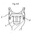
- Figs. 6a to 6dshow the assembly of the bone anchoring element 2.
- the ring 8is mounted on the head 4 of the bone anchoring element 2 and is accommodated by the annular groove 41 as shown in Fig. 6b and 6c .
- Fig. 6dshows the bone anchoring element 2 with mounted pressure element 6. When moving the pressure element 6 downwards in the direction of the shaft 3 the head 4 is maintained at an angular position by friction.
- the bone anchoring device 1In use, first, the bone anchoring device 1 is provided in a pre-assembled state with the pressure element 6 being in the first position in which the head 4 is temporarily frictionally clamped. Usually several bone anchoring devices 1 are necessary. The screw members 2 are then screwed into the bone or a vertebra and then the receiving parts 5 are pivoted by applying a force to overcome the clamping force until each receiving part 5 has the correct orientation for the insertion of the rod 20. Due to the temporary clamping, the receiving part 5 is held in this angular position. The rod 20, which connects the bone anchoring devices 1, is inserted and the inner screw 7 is tightened to move the pressure element 6 downwards to lock the head 4 so that the angular position of the screw member 2 with respect to the receiving part 5 is fixed. The rod 20 is then fixed by the inner screw 7.
- anchoring elementall kinds of anchoring elements can be used and combined with a receiving part.
- These anchoring elementsare e.g. screws of different length, with different diameters, cannulated screws, screws with different thread forms, nails, etc.
- the head and the shaftcan be separate parts which can be connected to each other.
- receiving partscan be used in particular such with different locking devices.
- the one-part locking devicesuch as the inner screw which locks the rod and the head simultaneously
- a two-part locking devices with an outer screw and an inner screwcan be used instead of the one-part locking device.
- the pressure elementhas an U-shaped recess with legs extending above the rod.
- outer nuts, outer caps, bayonet locking devices or othersare also possible.
- the shape of the receiving partis not limited to the embodiment shown.
- the receiving partcan have an asymmetric end portion for allowing a greater pivot angle of the screw member to one side.
- the annular grooveis not provided on the head but on the inner wall of the receiving part for accommodating the ring.
- the ring and the headcooperate in such a way that the pressure element exerts a preload force onto the head via the ring in which the head is maintained at an angular position by friction before locking the head 4.
- a ringis provided which is made of a non-flexible material such as PEEK for example.
- PEEKa non-flexible material
- Such ringshould only have a slight oversize with respect to the surface of the head, to ensure the frictional contact.
- the ring's cross-sectioncan also be substantially oval, rectangular, etc. or can vary over the circumference of the ring.
- the receiving partis configured to allow the introduction of the screw element from the bottom end.
Landscapes
- Health & Medical Sciences (AREA)
- Orthopedic Medicine & Surgery (AREA)
- Life Sciences & Earth Sciences (AREA)
- Surgery (AREA)
- Neurology (AREA)
- Heart & Thoracic Surgery (AREA)
- Engineering & Computer Science (AREA)
- Biomedical Technology (AREA)
- Nuclear Medicine, Radiotherapy & Molecular Imaging (AREA)
- Medical Informatics (AREA)
- Molecular Biology (AREA)
- Animal Behavior & Ethology (AREA)
- General Health & Medical Sciences (AREA)
- Public Health (AREA)
- Veterinary Medicine (AREA)
- Surgical Instruments (AREA)
Abstract
Description
- The invention relates to a bone anchoring device for anchoring a stabilization rod in a bone or in a vertebra. The bone anchoring device includes an anchoring element, a receiving part for receiving a head of the bone anchoring element and for receiving a stabilization rod to be connected to the anchoring element. The anchoring element is pivotably connected to the receiving part and can be fixed at an angle by exerting pressure onto the head via a pressure element which is arranged in the receiving part. The head comprises a recess which accommodates a closed ring which is configured to cooperate in such a way with the head and the pressure element that the pressure element can assume a position within the receiving part in which it clamps the head via the ring by friction without locking it.
US 2004/0267264 Al describes a polyaxial fixation device, wherein the polyaxial bone screw includes an engagement member that is adapted to provide sufficient friction between the spherical head and the receiver member to enable the shank to be maintained in a desired angular orientation before locking the spherical head within the receiver member. The engagement member is realized, for example, by an open snap ring around the head or by spring members provided at the compression cap to frictionally engage the spherical head or by a slot provided in the compression cap.- It is an object of the invention to provide a bone anchoring device which allows an improved handling during surgery and which can be manufactured cost-effectively in a simple manner.
- The object is solved by a bone anchoring device according to claim 1. Further developments are given in the dependent claims.
- With the bone anchoring device a temporary clamping of the head in a desired angular position with respect to the receiving part without locking the head can be achieved. This allows the receiving part to be held in an adjustable angular position. In this position the pressure element exerts a preload onto the head via the ring in which the head is not locked but frictionally prevented from freely pivoting. When the head is temporarily clamped the alignment of the receiving part to the rod and the insertion of the rod is facilitated. Also, when the rod is already inserted into the receiving part, adjustments of the rod are still possible without completely loosening the head within the receiving part. Finally, the pressure element can be pressed onto the head to lock the head in its desired portion.
- In addition, the bone anchoring device has only few parts which are of simple design.
- Furthermore, the heads of already manufactured bone anchoring devices can easily be upgraded to the system according to the present invention. Only a groove around the head and a closed ring which is accommodated by the groove have to be provided.
- The parts of the bone anchoring device can be manufactured in series at low costs.
- Further features and advantages of the invention will become apparent from the description of embodiments by means of the accompanying drawings.
- In the drawings:
- Fig. 1
- shows a perspective exploded view of the bone anchoring device.
- Fig. 2
- shows the bone anchoring device of
Fig. 1 in an assembled state. - Fig. 3 a
- a perspective view of the bone anchoring element.
- Fig. 3b
- shows a cross-sectional view of the bone anchoring element, the cross-section being taken in a plane containing the screw axis.
- Fig. 3c
- shows a top view of the bone anchoring element.
- Fig. 4a
- shows a perspective view of the ring.
- Fig. 4b
- shows a side view of the ring.
- Fig. 4c
- shows a cross-sectional view of the ring.
- Fig. 4d
- shows a top view of the ring.
- Fig. 5a
- shows a cross-sectional view of the bone anchoring device in an assembled state before fmal locking of the head.
- Fig. 5b
- shows an enlarged portion of
Fig. 5a . - Fig. 6a
- shows a cross-sectional exploded view of the bone anchoring element and the ring.
- Fig. 6b
- shows a cross sectional view of the bone anchoring element and the ring in an assembled state.
- Fig. 6c
- shows an enlarged portion of
Fig. 6b . - Fig. 6d
- shows a cross sectional view of the bone anchoring element, the ring and the pressure element in an assembled state.
- The polyaxial bone anchoring device 1 according to a first embodiment as shown in
Figs. 1, 2 and5a includes abone anchoring element 2 in the form of ascrew member 2 having a threadedshaft 3 and ahead 4. Thehead 4 includes atool recess 4a at its free end for engagement with a tool (not shown) to insert the threadedshaft 3 into the bone. The bone anchoring device 1 further includes a receivingpart 5 for connecting thescrew member 2 to arod 20. Apressure element 6 is arranged in the receivingpart 5 on top of thehead 4. For securing therod 20 in the receivingpart 5 and for exerting pressure onto thehead 4, a locking device, for example aninner screw 7, which cooperates with the receivingpart 5, is provided. - As shown in
Figs 3a, 3b and 3c , thehead 4 is shaped as spherical segment having a flat free end and having thetool recess 4a at the flat free end. Anannular groove 41 is provided at a position above the greatest diameter in a direction towards the free end. The cross-section of theannular groove 41 is substantially trapezoidal with an open side, as can be seen fromFig. 6a . Theannular groove 41 serves for accommodation of aring 8. The ground of theannular groove 41 is substantially coaxial to the axis of thescrew member 2. The edges on the ground of theannular groove 41 can be rounded. The free end of thehead 4 can also differ from the flat form. - The receiving
part 5 is a substantially cylindrical one piece part and has atop end 51 and abottom end 52. A passageway extending from thetop end 51 to thebottom end 52 is formed by acoaxial bore 53 followed by aseat portion 54 for receiving thehead 4 of thescrew member 2. Theseat portion 54 has anopening 55 at thebottom end 52 through which theshaft 3 of thescrew member 2 extends. Theseat portion 54 is shown to be spherically-shaped, but it can be tapered or it can have any other shape that allows to receive thehead 4 so that it can pivot with respect to the receivingpart 5. At the top end 51 a substantiallyU-shaped recess 56 is provided by means of which twofree legs rod 20. Aninternal thread 59 is provided at the legs for cooperating with theinner screw 7. - The receiving
part 5 further comprises at a distance from thebottom end 52 which is smaller than the distance from thetop end 51 two blind holes 500a, 500b forming crimp bores that extend from the outer surface to a distance from the inner wall of thecoaxial bore 53 for crimping in a manner described below. The blind holes 500a, 500b are arranged at 180° offset from each other and at 90° with respect to the channel formed by theU-shaped recess 56. The blind holes 500a, 500b are aligned perpendicular with respect to the bore axis of thecoaxial bore 53. The portions of the receivingpart 5 that are between the closed ends of the blind holes 500a, 500b and thecoaxial bore 53 of the receivingpart 5 are configured to be deformable portions. - The
pressure element 6 is formed in one piece. It is of substantially cylindrical construction and has an outer diameter, which allows it to move in the axial direction within thebore 53 of the receivingpart 5. Thepressure element 6 has atop end 61 and abottom end 62. When thepressure element 6 is inserted into the receivingpart 5, thebottom end 62 faces thehead 4 of thescrew element 2. At thetop end 61, aU-shaped recess 64 is provided by means of which twofree legs rod 20 therein. Furthermore, thepressure element 6 includes acoaxial bore 67 for accessing thescrew head 4 with a tool (not shown). As shown inFigs. 1 and 2 ., thepressure element 6 is a solid member which is arranged in the receivingpart 5 such that theU-shaped recess 56 of the receivingpart 5 and theU-shaped recess 64 of thepressure element 6 are aligned. - The
pressure element 6 includes two crimp bores corresponding to the crimp bores 500a, 500b of the receivingpart 5 wherein after crimping thepressure element 6 is held in a rotationally aligned position and at an axial position in which it can exert slight preload onto thehead 4. Fig. 4a to 4d show thering 8. As shown inFig. 4c thering 8 is closed. It has a substantially circular cross-section in an undeformed state. Thering 8 is made of a plastic material which is elastically deformable, for example a bio-compatible elastomer. As an elastomer, for example UHMWPE (Ultra-high-molecular-weight polyethylene), Silicon, PCU, SIBS or combinations thereof can be used. The other parts of the bone anchoring device 1 are made of a body-compatible material, such as a body-compatible metal, for example, titanium, body-compatible metal alloys such as, for example, Nitinol or from a body-compatible plastic material, such as, for example, PEEK or combinations thereof.- The size of the
ring 8 is such that when the ring is inserted into theannular groove 41 it is substantially undeformed and projects slightly out of theannular groove 41. Since the cross-section of theannular groove 41 is trapezoidal theannular groove 41 provides space for the deformation of thering 8 upon exertion of a load onto thering 8 by thepressure element 6. - In the assembled state as shown in
Fig. 5a , thehead 4 is located in theseat 54 and thepressure element 6 is arranged on top of thehead 4. The height of thefree legs pressure element 6 is configured such that thefree legs rod 20 when the rod is inserted and rests on the bottom of the channel. Thepressure element 6 as shown inFig. 5a and 5b can assume a first position which is defined by connecting thepressure element 6 and the receivingpart 5 by crimping through the crimp bores 500a, 500b, 600a, 600b, in which thering 8 and thepressure element 6 cooperate in such a way that thepressure element 6 exerts a preload force onto thehead 4 via thering 8 in which thehead 4 is maintained at an angular position by friction before locking thehead 4. The force is exerted onto thehead 4 via theinner screw 7, therod 20, thepressure element 6 and thering 8. Thering 8 which has a substantially circular cross-section is deformed such that its cross-section is substantially oval in this first position. By the deformation, thering 8 exerts a counter force onto thepressure element 6 so that thehead 4 is maintained in an angular position. This position can be adjusted by applying a force to thescrew member 2 to overcome the friction force. Thepressure element 6 can also assume a second position in which thehead 4 is locked by screwing in theinner screw 7. Furthermore, thepressure element 6 can assume third positions in which thehead 4 is capable of freely pivoting. In these positions thepressure element 6 is substantially not in frictional contact with thering 8. By selecting the size of thering 8 and the size of theannular groove 41, a desired friction force can be achieved. Figs. 6a to 6d show the assembly of thebone anchoring element 2. Thering 8 is mounted on thehead 4 of thebone anchoring element 2 and is accommodated by theannular groove 41 as shown inFig. 6b and 6c .Fig. 6d shows thebone anchoring element 2 with mountedpressure element 6. When moving thepressure element 6 downwards in the direction of theshaft 3 thehead 4 is maintained at an angular position by friction.- In use, first, the bone anchoring device 1 is provided in a pre-assembled state with the
pressure element 6 being in the first position in which thehead 4 is temporarily frictionally clamped. Usually several bone anchoring devices 1 are necessary. Thescrew members 2 are then screwed into the bone or a vertebra and then the receivingparts 5 are pivoted by applying a force to overcome the clamping force until each receivingpart 5 has the correct orientation for the insertion of therod 20. Due to the temporary clamping, the receivingpart 5 is held in this angular position. Therod 20, which connects the bone anchoring devices 1, is inserted and theinner screw 7 is tightened to move thepressure element 6 downwards to lock thehead 4 so that the angular position of thescrew member 2 with respect to the receivingpart 5 is fixed. Therod 20 is then fixed by theinner screw 7. - For the anchoring element all kinds of anchoring elements can be used and combined with a receiving part. These anchoring elements are e.g. screws of different length, with different diameters, cannulated screws, screws with different thread forms, nails, etc. The head and the shaft can be separate parts which can be connected to each other.
- Various kinds of receiving parts can be used in particular such with different locking devices. For example, instead of the one-part locking device such as the inner screw which locks the rod and the head simultaneously, a two-part locking devices with an outer screw and an inner screw can be used. In this case the pressure element has an U-shaped recess with legs extending above the rod. With the two-part locking device the head and the rod can be fixed independently. Further, outer nuts, outer caps, bayonet locking devices or others are also possible. The shape of the receiving part is not limited to the embodiment shown. For example, the receiving part can have an asymmetric end portion for allowing a greater pivot angle of the screw member to one side.
- In a modification the annular groove is not provided on the head but on the inner wall of the receiving part for accommodating the ring. The ring and the head cooperate in such a way that the pressure element exerts a preload force onto the head via the ring in which the head is maintained at an angular position by friction before locking the
head 4. - In a further modification a ring is provided which is made of a non-flexible material such as PEEK for example. Such ring should only have a slight oversize with respect to the surface of the head, to ensure the frictional contact. Further, the ring's cross-section can also be substantially oval, rectangular, etc. or can vary over the circumference of the ring.
- It is also possible to use one or several flexible elements which are arranged in the annular groove of the head or the pressure element, instead of using one single ring. The cross-sections of these elements or the ring, respectively may also vary.
- In a further modification, the receiving part is configured to allow the introduction of the screw element from the bottom end.
Claims (10)
- A bone anchoring device (1) includingan anchoring element (2) having a shaft (3) for anchoring in the bone and a head (4),a receiving part (5) having a top end (51) and a bottom end (52), a recess (56) for receiving a rod (20) therein, a coaxial bore (53) extending from the top end (51) in the direction of the bottom end (52) and a seat (54) for receiving the head (4) near the bottom end (52);a pressure element (6) which is movable within the bore (53);an element (8) made of a polymer material which is arranged between the head (4) and the pressure element (6);wherein the head (4) is pivotable with respect to the receiving part (5) and can be fixed at an angle by exerting pressure via the pressure element (6) onto the head (4), andwherein the pressure element (6) can assume a first position in which the element (8) and the pressure element (6) are in direct contact such that the pressure element (6) exerts a preload force onto the head (4) via the element (8) in which the head (4) is maintained at an angular position by friction before locking the head (4).
- The bone anchoring device (1) of claim 1, wherein the pressure element (6) can assume a second position in which it presses onto the head (4) such that the head (4) is locked.
- The bone anchoring device (1) of claim 1 or 2, wherein the element (8) is a closed ring (8).
- The bone anchoring device (1) of one of claims 1 to 3, wherein the head (4) comprises a groove (41) which is formed such that it can accommodate the element (8).
- The bone anchoring device (1) of claim 4, wherein the head (4) is spherical having a free end and the groove (41) is located at a position above the greatest diameter of the head (4) in a direction towards the free end.
- The bone anchoring device (1) of one of claims 1 to 3, wherein the pressure element (6) comprises a groove (41) which is formed such that it can accommodate the element (8).
- The bone anchoring device (1) of one of claims 1 to 6, wherein when the pressure element (6) is in the first position the element (8) has a slight oversize with respect to the annular groove (41) so that between the element (8) and the pressure element (6) a friction fit is achieved.
- The bone anchoring device (1) of one of claims 1 to 7, wherein the element (8) is made of an elastomer material.
- The bone anchoring device (1) of one of claims 1 to 8, wherein the cross-section of the element (8) is substantially circular in an undeformed state.
- The bone anchoring device (1) of one of claims 1 to 9, wherein a fixation element (7) is provided for fixing the rod (20).
Priority Applications (10)
| Application Number | Priority Date | Filing Date | Title |
|---|---|---|---|
| ES10196880.8TES2461843T3 (en) | 2010-12-23 | 2010-12-23 | Bone anchoring device |
| EP10196880.8AEP2468198B1 (en) | 2010-12-23 | 2010-12-23 | Bone anchoring device |
| CN201110428639.6ACN102525620B (en) | 2010-12-23 | 2011-12-20 | Bone anchoring device |
| KR1020110138379AKR20120072322A (en) | 2010-12-23 | 2011-12-20 | Bone anchoring device |
| TW100147235ATW201225903A (en) | 2010-12-23 | 2011-12-20 | Bone anchoring device |
| JP2011278133AJP5917905B2 (en) | 2010-12-23 | 2011-12-20 | Bone anchor device |
| US13/336,708US10433877B2 (en) | 2010-12-23 | 2011-12-23 | Bone anchoring device |
| US16/552,661US11123109B2 (en) | 2010-12-23 | 2019-08-27 | Bone anchoring device |
| US17/403,343US11992243B2 (en) | 2010-12-23 | 2021-08-16 | Bone anchoring device |
| US18/654,633US20240350177A1 (en) | 2010-12-23 | 2024-05-03 | Bone anchoring device |
Applications Claiming Priority (1)
| Application Number | Priority Date | Filing Date | Title |
|---|---|---|---|
| EP10196880.8AEP2468198B1 (en) | 2010-12-23 | 2010-12-23 | Bone anchoring device |
Publications (2)
| Publication Number | Publication Date |
|---|---|
| EP2468198A1true EP2468198A1 (en) | 2012-06-27 |
| EP2468198B1 EP2468198B1 (en) | 2014-02-19 |
Family
ID=43927781
Family Applications (1)
| Application Number | Title | Priority Date | Filing Date |
|---|---|---|---|
| EP10196880.8AActiveEP2468198B1 (en) | 2010-12-23 | 2010-12-23 | Bone anchoring device |
Country Status (7)
| Country | Link |
|---|---|
| US (4) | US10433877B2 (en) |
| EP (1) | EP2468198B1 (en) |
| JP (1) | JP5917905B2 (en) |
| KR (1) | KR20120072322A (en) |
| CN (1) | CN102525620B (en) |
| ES (1) | ES2461843T3 (en) |
| TW (1) | TW201225903A (en) |
Cited By (19)
| Publication number | Priority date | Publication date | Assignee | Title |
|---|---|---|---|---|
| EP2620112A1 (en)* | 2012-01-30 | 2013-07-31 | Biedermann Technologies GmbH & Co. KG | Bone anchoring device |
| FR2993170A1 (en)* | 2012-07-12 | 2014-01-17 | Clariance | Friction device for connecting poly-axial screw to connector of spinal fixation device, has ring and bushing positioned against spherical head of screw, to axially pre-position connector relative to axial anchoring position of screw |
| GB2507620A (en)* | 2010-11-02 | 2014-05-07 | Roger P Jackson | Polyaxial bone anchor with pop-on shank and pivotable retainer |
| WO2016168163A1 (en)* | 2015-04-13 | 2016-10-20 | Medos International Sarl | Bone anchor assemblies with orientation indicator |
| US9636146B2 (en) | 2012-01-10 | 2017-05-02 | Roger P. Jackson | Multi-start closures for open implants |
| US9662143B2 (en) | 2004-02-27 | 2017-05-30 | Roger P Jackson | Dynamic fixation assemblies with inner core and outer coil-like member |
| US9668771B2 (en) | 2009-06-15 | 2017-06-06 | Roger P Jackson | Soft stabilization assemblies with off-set connector |
| US9717533B2 (en) | 2013-12-12 | 2017-08-01 | Roger P. Jackson | Bone anchor closure pivot-splay control flange form guide and advancement structure |
| US9717534B2 (en) | 2009-06-15 | 2017-08-01 | Roger P. Jackson | Polyaxial bone anchor with pop-on shank and friction fit retainer with low profile edge lock |
| US9770265B2 (en) | 2012-11-21 | 2017-09-26 | Roger P. Jackson | Splay control closure for open bone anchor |
| US10058354B2 (en) | 2013-01-28 | 2018-08-28 | Roger P. Jackson | Pivotal bone anchor assembly with frictional shank head seating surfaces |
| US10064658B2 (en) | 2014-06-04 | 2018-09-04 | Roger P. Jackson | Polyaxial bone anchor with insert guides |
| US10349983B2 (en) | 2003-05-22 | 2019-07-16 | Alphatec Spine, Inc. | Pivotal bone anchor assembly with biased bushing for pre-lock friction fit |
| US10383660B2 (en) | 2007-05-01 | 2019-08-20 | Roger P. Jackson | Soft stabilization assemblies with pretensioned cords |
| US10470801B2 (en) | 2007-01-18 | 2019-11-12 | Roger P. Jackson | Dynamic spinal stabilization with rod-cord longitudinal connecting members |
| EP3766443A1 (en)* | 2019-07-18 | 2021-01-20 | Biedermann Technologies GmbH & Co. KG | Bone anchoring device |
| US11147591B2 (en) | 2004-11-10 | 2021-10-19 | Roger P Jackson | Pivotal bone anchor receiver assembly with threaded closure |
| US11191571B2 (en) | 2020-02-25 | 2021-12-07 | Biedermann Technologies Gmbh & Co. Kg | Bone anchoring device |
| US11229457B2 (en) | 2009-06-15 | 2022-01-25 | Roger P. Jackson | Pivotal bone anchor assembly with insert tool deployment |
Families Citing this family (33)
| Publication number | Priority date | Publication date | Assignee | Title |
|---|---|---|---|---|
| US8366753B2 (en) | 2003-06-18 | 2013-02-05 | Jackson Roger P | Polyaxial bone screw assembly with fixed retaining structure |
| US8926670B2 (en) | 2003-06-18 | 2015-01-06 | Roger P. Jackson | Polyaxial bone screw assembly |
| US7776067B2 (en) | 2005-05-27 | 2010-08-17 | Jackson Roger P | Polyaxial bone screw with shank articulation pressure insert and method |
| US8926672B2 (en) | 2004-11-10 | 2015-01-06 | Roger P. Jackson | Splay control closure for open bone anchor |
| US8444681B2 (en) | 2009-06-15 | 2013-05-21 | Roger P. Jackson | Polyaxial bone anchor with pop-on shank, friction fit retainer and winged insert |
| US9216041B2 (en) | 2009-06-15 | 2015-12-22 | Roger P. Jackson | Spinal connecting members with tensioned cords and rigid sleeves for engaging compression inserts |
| US9980753B2 (en) | 2009-06-15 | 2018-05-29 | Roger P Jackson | pivotal anchor with snap-in-place insert having rotation blocking extensions |
| US9168069B2 (en) | 2009-06-15 | 2015-10-27 | Roger P. Jackson | Polyaxial bone anchor with pop-on shank and winged insert with lower skirt for engaging a friction fit retainer |
| US7901437B2 (en) | 2007-01-26 | 2011-03-08 | Jackson Roger P | Dynamic stabilization member with molded connection |
| US8007522B2 (en) | 2008-02-04 | 2011-08-30 | Depuy Spine, Inc. | Methods for correction of spinal deformities |
| CN103826560A (en) | 2009-06-15 | 2014-05-28 | 罗杰.P.杰克逊 | Polyaxial Bone Anchor with Socket Stem and Winged Inserts with Friction Fit Compression Collars |
| US11464549B2 (en) | 2009-06-15 | 2022-10-11 | Roger P. Jackson | Pivotal bone anchor assembly with horizontal tool engagement grooves and insert with upright arms having flared outer portions |
| EP2485654B1 (en) | 2009-10-05 | 2021-05-05 | Jackson P. Roger | Polyaxial bone anchor with non-pivotable retainer and pop-on shank, some with friction fit |
| AU2011299558A1 (en) | 2010-09-08 | 2013-05-02 | Roger P. Jackson | Dynamic stabilization members with elastic and inelastic sections |
| EP2659845A1 (en) | 2010-12-27 | 2013-11-06 | Biedermann Technologies GmbH & Co. KG | Polyaxial bone anchoring device |
| JP5865479B2 (en)* | 2011-03-24 | 2016-02-17 | ロジャー・ピー・ジャクソン | Multiaxial bone anchor with compound joint and pop-mounted shank |
| US9782204B2 (en) | 2012-09-28 | 2017-10-10 | Medos International Sarl | Bone anchor assemblies |
| US8852239B2 (en) | 2013-02-15 | 2014-10-07 | Roger P Jackson | Sagittal angle screw with integral shank and receiver |
| US10342582B2 (en) | 2013-03-14 | 2019-07-09 | DePuy Synthes Products, Inc. | Bone anchor assemblies and methods with improved locking |
| US9724145B2 (en) | 2013-03-14 | 2017-08-08 | Medos International Sarl | Bone anchor assemblies with multiple component bottom loading bone anchors |
| US9259247B2 (en) | 2013-03-14 | 2016-02-16 | Medos International Sarl | Locking compression members for use with bone anchor assemblies and methods |
| US9775660B2 (en)* | 2013-03-14 | 2017-10-03 | DePuy Synthes Products, Inc. | Bottom-loading bone anchor assemblies and methods |
| US9566092B2 (en) | 2013-10-29 | 2017-02-14 | Roger P. Jackson | Cervical bone anchor with collet retainer and outer locking sleeve |
| US9451993B2 (en) | 2014-01-09 | 2016-09-27 | Roger P. Jackson | Bi-radial pop-on cervical bone anchor |
| US9597119B2 (en) | 2014-06-04 | 2017-03-21 | Roger P. Jackson | Polyaxial bone anchor with polymer sleeve |
| CN108697445B (en) | 2016-02-26 | 2022-04-19 | 美多斯国际有限公司 | Polyaxial bone fixation element |
| US11026730B2 (en) | 2017-05-10 | 2021-06-08 | Medos International Sarl | Bone anchors with drag features and related methods |
| US10610265B1 (en) | 2017-07-31 | 2020-04-07 | K2M, Inc. | Polyaxial bone screw with increased angulation |
| USD956233S1 (en)* | 2020-04-24 | 2022-06-28 | Solco Biomedical Co., Ltd. | Cervical screw |
| WO2021263088A1 (en) | 2020-06-26 | 2021-12-30 | K2M, Inc. | Modular head assembly |
| WO2022108875A1 (en) | 2020-11-19 | 2022-05-27 | K2M, Inc. | Modular head assembly for spinal fixation |
| US12364515B2 (en) | 2021-03-05 | 2025-07-22 | Medos International Sàrl | Multi-feature polyaxial screw |
| WO2022184797A1 (en) | 2021-03-05 | 2022-09-09 | Medos International Sarl | Selectively locking polyaxial screw |
Citations (4)
| Publication number | Priority date | Publication date | Assignee | Title |
|---|---|---|---|---|
| US20040267264A1 (en) | 2003-06-27 | 2004-12-30 | Konieczynski David D. | Polyaxial bone screw |
| US20060173456A1 (en)* | 2005-01-31 | 2006-08-03 | Hawkes David T | Polyaxial pedicle screw assembly |
| US20080269809A1 (en)* | 2007-03-26 | 2008-10-30 | Laszlo Garamszegi | Bottom-loading pedicle screw assembly |
| WO2009132110A1 (en)* | 2008-04-22 | 2009-10-29 | Synthes Usa, Llc | Bone fixation element with reduction tabs |
Family Cites Families (22)
| Publication number | Priority date | Publication date | Assignee | Title |
|---|---|---|---|---|
| DE19720782B4 (en)* | 1997-05-17 | 2004-12-09 | Synthes Ag Chur, Chur | Device for connecting a side member to a pedicle screw |
| US6248105B1 (en) | 1997-05-17 | 2001-06-19 | Synthes (U.S.A.) | Device for connecting a longitudinal support with a pedicle screw |
| US6113601A (en)* | 1998-06-12 | 2000-09-05 | Bones Consulting, Llc | Polyaxial pedicle screw having a loosely coupled locking cap |
| US7001389B1 (en)* | 2002-07-05 | 2006-02-21 | Navarro Richard R | Fixed and variable locking fixation assembly |
| WO2006047711A2 (en)* | 2004-10-25 | 2006-05-04 | Alphaspine, Inc. | Pedicle screw systems and methods |
| US8353939B2 (en)* | 2005-01-12 | 2013-01-15 | Warsaw Orthopedic, Inc. | Anchor retaining mechanisms for bone plates |
| US10076361B2 (en)* | 2005-02-22 | 2018-09-18 | Roger P. Jackson | Polyaxial bone screw with spherical capture, compression and alignment and retention structures |
| EP1741396B1 (en) | 2005-07-08 | 2009-09-23 | BIEDERMANN MOTECH GmbH | Bone anchoring device |
| US20070118117A1 (en)* | 2005-10-20 | 2007-05-24 | Ebi, L.P. | Bone fixation assembly |
| US8057519B2 (en)* | 2006-01-27 | 2011-11-15 | Warsaw Orthopedic, Inc. | Multi-axial screw assembly |
| US20080015597A1 (en)* | 2006-04-28 | 2008-01-17 | Whipple Dale E | Large diameter bone anchor assembly |
| US7806913B2 (en)* | 2006-08-16 | 2010-10-05 | Depuy Spine, Inc. | Modular multi-level spine stabilization system and method |
| US7867258B2 (en) | 2006-10-17 | 2011-01-11 | Warsaw Orthopedic, Inc. | Multi-axial bone attachment member |
| ES2373770T3 (en)* | 2006-11-22 | 2012-02-08 | Biedermann Motech Gmbh | BONE ANCHORAGE DEVICE. |
| ES2390174T3 (en)* | 2008-07-24 | 2012-11-07 | Mitsubishi Electric Corporation | Train braking device |
| EP2160988B1 (en)* | 2008-09-04 | 2012-12-26 | Biedermann Technologies GmbH & Co. KG | Rod-shaped implant in particular for stabilizing the spinal column and stabilization device including such a rod-shaped implant |
| ES2375879T3 (en)* | 2008-12-23 | 2012-03-07 | Biedermann Motech Gmbh | RECEPTION AREA OF A ROD FOR COUPLING THE ROD IN AN BONE ANCHORAGE ELEMENT AND BONE ANCHORAGE DEVICE WITH SUCH RECEPTION AREA. |
| US8361123B2 (en)* | 2009-10-16 | 2013-01-29 | Depuy Spine, Inc. | Bone anchor assemblies and methods of manufacturing and use thereof |
| WO2012030712A1 (en)* | 2010-08-30 | 2012-03-08 | Zimmer Spine, Inc. | Polyaxial pedicle screw |
| AU2011324058A1 (en)* | 2010-11-02 | 2013-06-20 | Roger P. Jackson | Polyaxial bone anchor with pop-on shank and pivotable retainer |
| US8734495B2 (en)* | 2012-01-18 | 2014-05-27 | Globus Medical, Inc. | Securing fasteners |
| EP3766443B1 (en)* | 2019-07-18 | 2023-02-15 | Biedermann Technologies GmbH & Co. KG | Bone anchoring device |
- 2010
- 2010-12-23ESES10196880.8Tpatent/ES2461843T3/enactiveActive
- 2010-12-23EPEP10196880.8Apatent/EP2468198B1/enactiveActive
- 2011
- 2011-12-20CNCN201110428639.6Apatent/CN102525620B/ennot_activeExpired - Fee Related
- 2011-12-20TWTW100147235Apatent/TW201225903A/enunknown
- 2011-12-20KRKR1020110138379Apatent/KR20120072322A/ennot_activeWithdrawn
- 2011-12-20JPJP2011278133Apatent/JP5917905B2/ennot_activeExpired - Fee Related
- 2011-12-23USUS13/336,708patent/US10433877B2/enactiveActive
- 2019
- 2019-08-27USUS16/552,661patent/US11123109B2/enactiveActive
- 2021
- 2021-08-16USUS17/403,343patent/US11992243B2/enactiveActive
- 2024
- 2024-05-03USUS18/654,633patent/US20240350177A1/enactivePending
Patent Citations (4)
| Publication number | Priority date | Publication date | Assignee | Title |
|---|---|---|---|---|
| US20040267264A1 (en) | 2003-06-27 | 2004-12-30 | Konieczynski David D. | Polyaxial bone screw |
| US20060173456A1 (en)* | 2005-01-31 | 2006-08-03 | Hawkes David T | Polyaxial pedicle screw assembly |
| US20080269809A1 (en)* | 2007-03-26 | 2008-10-30 | Laszlo Garamszegi | Bottom-loading pedicle screw assembly |
| WO2009132110A1 (en)* | 2008-04-22 | 2009-10-29 | Synthes Usa, Llc | Bone fixation element with reduction tabs |
Cited By (29)
| Publication number | Priority date | Publication date | Assignee | Title |
|---|---|---|---|---|
| US10349983B2 (en) | 2003-05-22 | 2019-07-16 | Alphatec Spine, Inc. | Pivotal bone anchor assembly with biased bushing for pre-lock friction fit |
| US9662143B2 (en) | 2004-02-27 | 2017-05-30 | Roger P Jackson | Dynamic fixation assemblies with inner core and outer coil-like member |
| US11147591B2 (en) | 2004-11-10 | 2021-10-19 | Roger P Jackson | Pivotal bone anchor receiver assembly with threaded closure |
| US10470801B2 (en) | 2007-01-18 | 2019-11-12 | Roger P. Jackson | Dynamic spinal stabilization with rod-cord longitudinal connecting members |
| US10383660B2 (en) | 2007-05-01 | 2019-08-20 | Roger P. Jackson | Soft stabilization assemblies with pretensioned cords |
| US11229457B2 (en) | 2009-06-15 | 2022-01-25 | Roger P. Jackson | Pivotal bone anchor assembly with insert tool deployment |
| US9717534B2 (en) | 2009-06-15 | 2017-08-01 | Roger P. Jackson | Polyaxial bone anchor with pop-on shank and friction fit retainer with low profile edge lock |
| US9668771B2 (en) | 2009-06-15 | 2017-06-06 | Roger P Jackson | Soft stabilization assemblies with off-set connector |
| GB2507620A (en)* | 2010-11-02 | 2014-05-07 | Roger P Jackson | Polyaxial bone anchor with pop-on shank and pivotable retainer |
| US9636146B2 (en) | 2012-01-10 | 2017-05-02 | Roger P. Jackson | Multi-start closures for open implants |
| US12193712B2 (en) | 2012-01-30 | 2025-01-14 | Biedermann Technologies Gmbh & Co. Kg | Bone anchoring device |
| US9597121B2 (en) | 2012-01-30 | 2017-03-21 | Biedermann Technologies Gmbh & Co. Kg | Bone anchoring device |
| US9078705B2 (en) | 2012-01-30 | 2015-07-14 | Biedermann Technologies Gmbh & Co. Kg | Bone anchoring device |
| EP2620112A1 (en)* | 2012-01-30 | 2013-07-31 | Biedermann Technologies GmbH & Co. KG | Bone anchoring device |
| US11058462B2 (en) | 2012-01-30 | 2021-07-13 | Biedermann Technologies Gmbh & Co. Kg | Bone anchoring device |
| US10335204B2 (en) | 2012-01-30 | 2019-07-02 | Biedermann Technologies Gmbh & Co. Kg | Bone anchoring device |
| EP2837347A3 (en)* | 2012-01-30 | 2015-04-22 | Biedermann Technologies GmbH & Co. KG | Bone anchoring device |
| US10448976B2 (en) | 2012-01-30 | 2019-10-22 | Biedermann Technologies Gmbh & Co. Kg | Bone anchoring device |
| FR2993170A1 (en)* | 2012-07-12 | 2014-01-17 | Clariance | Friction device for connecting poly-axial screw to connector of spinal fixation device, has ring and bushing positioned against spherical head of screw, to axially pre-position connector relative to axial anchoring position of screw |
| US9770265B2 (en) | 2012-11-21 | 2017-09-26 | Roger P. Jackson | Splay control closure for open bone anchor |
| US10058354B2 (en) | 2013-01-28 | 2018-08-28 | Roger P. Jackson | Pivotal bone anchor assembly with frictional shank head seating surfaces |
| US9717533B2 (en) | 2013-12-12 | 2017-08-01 | Roger P. Jackson | Bone anchor closure pivot-splay control flange form guide and advancement structure |
| US10064658B2 (en) | 2014-06-04 | 2018-09-04 | Roger P. Jackson | Polyaxial bone anchor with insert guides |
| US9833263B2 (en) | 2015-04-13 | 2017-12-05 | Medos International Sarl | Bone anchor assemblies with orientation indicator |
| WO2016168163A1 (en)* | 2015-04-13 | 2016-10-20 | Medos International Sarl | Bone anchor assemblies with orientation indicator |
| EP3766443A1 (en)* | 2019-07-18 | 2021-01-20 | Biedermann Technologies GmbH & Co. KG | Bone anchoring device |
| US11464546B2 (en) | 2019-07-18 | 2022-10-11 | Biedermann Technologies Gmbh & Co. Kg | Bone anchoring device |
| US11191571B2 (en) | 2020-02-25 | 2021-12-07 | Biedermann Technologies Gmbh & Co. Kg | Bone anchoring device |
| US12207846B2 (en) | 2020-02-25 | 2025-01-28 | Biedermann Technologies Gmbh & Co. Kg | Bone anchoring device |
Also Published As
| Publication number | Publication date |
|---|---|
| CN102525620A (en) | 2012-07-04 |
| US11123109B2 (en) | 2021-09-21 |
| EP2468198B1 (en) | 2014-02-19 |
| KR20120072322A (en) | 2012-07-03 |
| US20240350177A1 (en) | 2024-10-24 |
| JP5917905B2 (en) | 2016-05-18 |
| US20220031368A1 (en) | 2022-02-03 |
| US20120165881A1 (en) | 2012-06-28 |
| ES2461843T3 (en) | 2014-05-21 |
| US11992243B2 (en) | 2024-05-28 |
| TW201225903A (en) | 2012-07-01 |
| JP2012130697A (en) | 2012-07-12 |
| CN102525620B (en) | 2015-08-05 |
| US10433877B2 (en) | 2019-10-08 |
| US20200054364A1 (en) | 2020-02-20 |
Similar Documents
| Publication | Publication Date | Title |
|---|---|---|
| US20240350177A1 (en) | Bone anchoring device | |
| US12193712B2 (en) | Bone anchoring device | |
| US9333011B2 (en) | Polyaxial bone anchoring device | |
| US9924974B2 (en) | Polyaxial bone anchoring device | |
| EP3047812B1 (en) | Polyaxial bone anchoring device | |
| US9155568B2 (en) | Bone anchoring device | |
| US9486246B2 (en) | Bone anchoring device | |
| EP2559391A1 (en) | Polyaxial bone anchoring system |
Legal Events
| Date | Code | Title | Description |
|---|---|---|---|
| 17P | Request for examination filed | Effective date:20120105 | |
| AK | Designated contracting states | Kind code of ref document:A1 Designated state(s):AL AT BE BG CH CY CZ DE DK EE ES FI FR GB GR HR HU IE IS IT LI LT LU LV MC MK MT NL NO PL PT RO RS SE SI SK SM TR | |
| AX | Request for extension of the european patent | Extension state:BA ME | |
| PUAI | Public reference made under article 153(3) epc to a published international application that has entered the european phase | Free format text:ORIGINAL CODE: 0009012 | |
| GRAP | Despatch of communication of intention to grant a patent | Free format text:ORIGINAL CODE: EPIDOSNIGR1 | |
| INTG | Intention to grant announced | Effective date:20130409 | |
| GRAP | Despatch of communication of intention to grant a patent | Free format text:ORIGINAL CODE: EPIDOSNIGR1 | |
| INTG | Intention to grant announced | Effective date:20130903 | |
| GRAS | Grant fee paid | Free format text:ORIGINAL CODE: EPIDOSNIGR3 | |
| GRAA | (expected) grant | Free format text:ORIGINAL CODE: 0009210 | |
| AK | Designated contracting states | Kind code of ref document:B1 Designated state(s):AL AT BE BG CH CY CZ DE DK EE ES FI FR GB GR HR HU IE IS IT LI LT LU LV MC MK MT NL NO PL PT RO RS SE SI SK SM TR | |
| REG | Reference to a national code | Ref country code:GB Ref legal event code:FG4D | |
| REG | Reference to a national code | Ref country code:CH Ref legal event code:NV Representative=s name:NOVAGRAAF INTERNATIONAL SA, CH Ref country code:CH Ref legal event code:EP | |
| REG | Reference to a national code | Ref country code:AT Ref legal event code:REF Ref document number:652654 Country of ref document:AT Kind code of ref document:T Effective date:20140315 | |
| REG | Reference to a national code | Ref country code:DE Ref legal event code:R096 Ref document number:602010013619 Country of ref document:DE Effective date:20140403 | |
| REG | Reference to a national code | Ref country code:IE Ref legal event code:FG4D | |
| REG | Reference to a national code | Ref country code:ES Ref legal event code:FG2A Ref document number:2461843 Country of ref document:ES Kind code of ref document:T3 Effective date:20140521 | |
| REG | Reference to a national code | Ref country code:NL Ref legal event code:VDEP Effective date:20140219 | |
| REG | Reference to a national code | Ref country code:AT Ref legal event code:MK05 Ref document number:652654 Country of ref document:AT Kind code of ref document:T Effective date:20140219 | |
| REG | Reference to a national code | Ref country code:LT Ref legal event code:MG4D | |
| PG25 | Lapsed in a contracting state [announced via postgrant information from national office to epo] | Ref country code:NO Free format text:LAPSE BECAUSE OF FAILURE TO SUBMIT A TRANSLATION OF THE DESCRIPTION OR TO PAY THE FEE WITHIN THE PRESCRIBED TIME-LIMIT Effective date:20140519 Ref country code:IS Free format text:LAPSE BECAUSE OF FAILURE TO SUBMIT A TRANSLATION OF THE DESCRIPTION OR TO PAY THE FEE WITHIN THE PRESCRIBED TIME-LIMIT Effective date:20140619 Ref country code:LT Free format text:LAPSE BECAUSE OF FAILURE TO SUBMIT A TRANSLATION OF THE DESCRIPTION OR TO PAY THE FEE WITHIN THE PRESCRIBED TIME-LIMIT Effective date:20140219 | |
| PG25 | Lapsed in a contracting state [announced via postgrant information from national office to epo] | Ref country code:SE Free format text:LAPSE BECAUSE OF FAILURE TO SUBMIT A TRANSLATION OF THE DESCRIPTION OR TO PAY THE FEE WITHIN THE PRESCRIBED TIME-LIMIT Effective date:20140219 Ref country code:AT Free format text:LAPSE BECAUSE OF FAILURE TO SUBMIT A TRANSLATION OF THE DESCRIPTION OR TO PAY THE FEE WITHIN THE PRESCRIBED TIME-LIMIT Effective date:20140219 Ref country code:NL Free format text:LAPSE BECAUSE OF FAILURE TO SUBMIT A TRANSLATION OF THE DESCRIPTION OR TO PAY THE FEE WITHIN THE PRESCRIBED TIME-LIMIT Effective date:20140219 Ref country code:FI Free format text:LAPSE BECAUSE OF FAILURE TO SUBMIT A TRANSLATION OF THE DESCRIPTION OR TO PAY THE FEE WITHIN THE PRESCRIBED TIME-LIMIT Effective date:20140219 Ref country code:PT Free format text:LAPSE BECAUSE OF FAILURE TO SUBMIT A TRANSLATION OF THE DESCRIPTION OR TO PAY THE FEE WITHIN THE PRESCRIBED TIME-LIMIT Effective date:20140619 Ref country code:CY Free format text:LAPSE BECAUSE OF FAILURE TO SUBMIT A TRANSLATION OF THE DESCRIPTION OR TO PAY THE FEE WITHIN THE PRESCRIBED TIME-LIMIT Effective date:20140219 | |
| PG25 | Lapsed in a contracting state [announced via postgrant information from national office to epo] | Ref country code:RS Free format text:LAPSE BECAUSE OF FAILURE TO SUBMIT A TRANSLATION OF THE DESCRIPTION OR TO PAY THE FEE WITHIN THE PRESCRIBED TIME-LIMIT Effective date:20140219 Ref country code:BE Free format text:LAPSE BECAUSE OF FAILURE TO SUBMIT A TRANSLATION OF THE DESCRIPTION OR TO PAY THE FEE WITHIN THE PRESCRIBED TIME-LIMIT Effective date:20140219 Ref country code:LV Free format text:LAPSE BECAUSE OF FAILURE TO SUBMIT A TRANSLATION OF THE DESCRIPTION OR TO PAY THE FEE WITHIN THE PRESCRIBED TIME-LIMIT Effective date:20140219 Ref country code:HR Free format text:LAPSE BECAUSE OF FAILURE TO SUBMIT A TRANSLATION OF THE DESCRIPTION OR TO PAY THE FEE WITHIN THE PRESCRIBED TIME-LIMIT Effective date:20140219 | |
| PG25 | Lapsed in a contracting state [announced via postgrant information from national office to epo] | Ref country code:DK Free format text:LAPSE BECAUSE OF FAILURE TO SUBMIT A TRANSLATION OF THE DESCRIPTION OR TO PAY THE FEE WITHIN THE PRESCRIBED TIME-LIMIT Effective date:20140219 Ref country code:RO Free format text:LAPSE BECAUSE OF FAILURE TO SUBMIT A TRANSLATION OF THE DESCRIPTION OR TO PAY THE FEE WITHIN THE PRESCRIBED TIME-LIMIT Effective date:20140219 Ref country code:CZ Free format text:LAPSE BECAUSE OF FAILURE TO SUBMIT A TRANSLATION OF THE DESCRIPTION OR TO PAY THE FEE WITHIN THE PRESCRIBED TIME-LIMIT Effective date:20140219 Ref country code:EE Free format text:LAPSE BECAUSE OF FAILURE TO SUBMIT A TRANSLATION OF THE DESCRIPTION OR TO PAY THE FEE WITHIN THE PRESCRIBED TIME-LIMIT Effective date:20140219 | |
| REG | Reference to a national code | Ref country code:DE Ref legal event code:R097 Ref document number:602010013619 Country of ref document:DE | |
| PG25 | Lapsed in a contracting state [announced via postgrant information from national office to epo] | Ref country code:PL Free format text:LAPSE BECAUSE OF FAILURE TO SUBMIT A TRANSLATION OF THE DESCRIPTION OR TO PAY THE FEE WITHIN THE PRESCRIBED TIME-LIMIT Effective date:20140219 Ref country code:SK Free format text:LAPSE BECAUSE OF FAILURE TO SUBMIT A TRANSLATION OF THE DESCRIPTION OR TO PAY THE FEE WITHIN THE PRESCRIBED TIME-LIMIT Effective date:20140219 | |
| PLBE | No opposition filed within time limit | Free format text:ORIGINAL CODE: 0009261 | |
| STAA | Information on the status of an ep patent application or granted ep patent | Free format text:STATUS: NO OPPOSITION FILED WITHIN TIME LIMIT | |
| 26N | No opposition filed | Effective date:20141120 | |
| PG25 | Lapsed in a contracting state [announced via postgrant information from national office to epo] | Ref country code:RS Free format text:LAPSE BECAUSE OF FAILURE TO SUBMIT A TRANSLATION OF THE DESCRIPTION OR TO PAY THE FEE WITHIN THE PRESCRIBED TIME-LIMIT Effective date:20140903 | |
| REG | Reference to a national code | Ref country code:DE Ref legal event code:R097 Ref document number:602010013619 Country of ref document:DE Effective date:20141120 | |
| PG25 | Lapsed in a contracting state [announced via postgrant information from national office to epo] | Ref country code:SI Free format text:LAPSE BECAUSE OF FAILURE TO SUBMIT A TRANSLATION OF THE DESCRIPTION OR TO PAY THE FEE WITHIN THE PRESCRIBED TIME-LIMIT Effective date:20140219 | |
| PG25 | Lapsed in a contracting state [announced via postgrant information from national office to epo] | Ref country code:LU Free format text:LAPSE BECAUSE OF FAILURE TO SUBMIT A TRANSLATION OF THE DESCRIPTION OR TO PAY THE FEE WITHIN THE PRESCRIBED TIME-LIMIT Effective date:20141223 | |
| REG | Reference to a national code | Ref country code:IE Ref legal event code:MM4A | |
| PG25 | Lapsed in a contracting state [announced via postgrant information from national office to epo] | Ref country code:IE Free format text:LAPSE BECAUSE OF NON-PAYMENT OF DUE FEES Effective date:20141223 | |
| REG | Reference to a national code | Ref country code:FR Ref legal event code:PLFP Year of fee payment:6 | |
| PG25 | Lapsed in a contracting state [announced via postgrant information from national office to epo] | Ref country code:SM Free format text:LAPSE BECAUSE OF FAILURE TO SUBMIT A TRANSLATION OF THE DESCRIPTION OR TO PAY THE FEE WITHIN THE PRESCRIBED TIME-LIMIT Effective date:20140219 | |
| PG25 | Lapsed in a contracting state [announced via postgrant information from national office to epo] | Ref country code:MC Free format text:LAPSE BECAUSE OF FAILURE TO SUBMIT A TRANSLATION OF THE DESCRIPTION OR TO PAY THE FEE WITHIN THE PRESCRIBED TIME-LIMIT Effective date:20140219 | |
| PG25 | Lapsed in a contracting state [announced via postgrant information from national office to epo] | Ref country code:GR Free format text:LAPSE BECAUSE OF FAILURE TO SUBMIT A TRANSLATION OF THE DESCRIPTION OR TO PAY THE FEE WITHIN THE PRESCRIBED TIME-LIMIT Effective date:20140520 Ref country code:BG Free format text:LAPSE BECAUSE OF FAILURE TO SUBMIT A TRANSLATION OF THE DESCRIPTION OR TO PAY THE FEE WITHIN THE PRESCRIBED TIME-LIMIT Effective date:20140219 | |
| PG25 | Lapsed in a contracting state [announced via postgrant information from national office to epo] | Ref country code:HU Free format text:LAPSE BECAUSE OF FAILURE TO SUBMIT A TRANSLATION OF THE DESCRIPTION OR TO PAY THE FEE WITHIN THE PRESCRIBED TIME-LIMIT; INVALID AB INITIO Effective date:20101223 Ref country code:MT Free format text:LAPSE BECAUSE OF FAILURE TO SUBMIT A TRANSLATION OF THE DESCRIPTION OR TO PAY THE FEE WITHIN THE PRESCRIBED TIME-LIMIT Effective date:20140219 Ref country code:TR Free format text:LAPSE BECAUSE OF FAILURE TO SUBMIT A TRANSLATION OF THE DESCRIPTION OR TO PAY THE FEE WITHIN THE PRESCRIBED TIME-LIMIT Effective date:20140219 | |
| REG | Reference to a national code | Ref country code:FR Ref legal event code:PLFP Year of fee payment:7 | |
| PGFP | Annual fee paid to national office [announced via postgrant information from national office to epo] | Ref country code:FR Payment date:20161221 Year of fee payment:7 Ref country code:ES Payment date:20161221 Year of fee payment:7 | |
| PGFP | Annual fee paid to national office [announced via postgrant information from national office to epo] | Ref country code:IT Payment date:20161229 Year of fee payment:7 | |
| PG25 | Lapsed in a contracting state [announced via postgrant information from national office to epo] | Ref country code:MK Free format text:LAPSE BECAUSE OF FAILURE TO SUBMIT A TRANSLATION OF THE DESCRIPTION OR TO PAY THE FEE WITHIN THE PRESCRIBED TIME-LIMIT Effective date:20140219 | |
| REG | Reference to a national code | Ref country code:FR Ref legal event code:ST Effective date:20180831 | |
| PG25 | Lapsed in a contracting state [announced via postgrant information from national office to epo] | Ref country code:FR Free format text:LAPSE BECAUSE OF NON-PAYMENT OF DUE FEES Effective date:20180102 Ref country code:AL Free format text:LAPSE BECAUSE OF FAILURE TO SUBMIT A TRANSLATION OF THE DESCRIPTION OR TO PAY THE FEE WITHIN THE PRESCRIBED TIME-LIMIT Effective date:20140219 Ref country code:IT Free format text:LAPSE BECAUSE OF NON-PAYMENT OF DUE FEES Effective date:20171223 | |
| REG | Reference to a national code | Ref country code:ES Ref legal event code:FD2A Effective date:20190703 | |
| PG25 | Lapsed in a contracting state [announced via postgrant information from national office to epo] | Ref country code:ES Free format text:LAPSE BECAUSE OF NON-PAYMENT OF DUE FEES Effective date:20171224 | |
| P01 | Opt-out of the competence of the unified patent court (upc) registered | Effective date:20230526 | |
| PGFP | Annual fee paid to national office [announced via postgrant information from national office to epo] | Ref country code:DE Payment date:20241218 Year of fee payment:15 | |
| PGFP | Annual fee paid to national office [announced via postgrant information from national office to epo] | Ref country code:GB Payment date:20241213 Year of fee payment:15 | |
| PGFP | Annual fee paid to national office [announced via postgrant information from national office to epo] | Ref country code:CH Payment date:20250101 Year of fee payment:15 |