EP2467280B1 - System and method using a multi-plane curtain - Google Patents
System and method using a multi-plane curtainDownload PDFInfo
- Publication number
- EP2467280B1 EP2467280B1EP10810425.8AEP10810425AEP2467280B1EP 2467280 B1EP2467280 B1EP 2467280B1EP 10810425 AEP10810425 AEP 10810425AEP 2467280 B1EP2467280 B1EP 2467280B1
- Authority
- EP
- European Patent Office
- Prior art keywords
- vehicle
- scanning
- scanner
- safety zone
- signal
- Prior art date
- Legal status (The legal status is an assumption and is not a legal conclusion. Google has not performed a legal analysis and makes no representation as to the accuracy of the status listed.)
- Active
Links
- 239000000463materialSubstances0.000claimsdescription9
- 238000001514detection methodMethods0.000claimsdescription8
- 230000007246mechanismEffects0.000claimsdescription8
- 230000004044responseEffects0.000claimsdescription3
- 230000004048modificationEffects0.000description2
- 238000012986modificationMethods0.000description2
- 230000008901benefitEffects0.000description1
- 150000001875compoundsChemical class0.000description1
- 239000011521glassSubstances0.000description1
- 239000002184metalSubstances0.000description1
- 230000003287optical effectEffects0.000description1
Images


Classifications
- B—PERFORMING OPERATIONS; TRANSPORTING
- B60—VEHICLES IN GENERAL
- B60R—VEHICLES, VEHICLE FITTINGS, OR VEHICLE PARTS, NOT OTHERWISE PROVIDED FOR
- B60R1/00—Optical viewing arrangements; Real-time viewing arrangements for drivers or passengers using optical image capturing systems, e.g. cameras or video systems specially adapted for use in or on vehicles
- G—PHYSICS
- G01—MEASURING; TESTING
- G01S—RADIO DIRECTION-FINDING; RADIO NAVIGATION; DETERMINING DISTANCE OR VELOCITY BY USE OF RADIO WAVES; LOCATING OR PRESENCE-DETECTING BY USE OF THE REFLECTION OR RERADIATION OF RADIO WAVES; ANALOGOUS ARRANGEMENTS USING OTHER WAVES
- G01S7/00—Details of systems according to groups G01S13/00, G01S15/00, G01S17/00
- G01S7/48—Details of systems according to groups G01S13/00, G01S15/00, G01S17/00 of systems according to group G01S17/00
- G01S7/481—Constructional features, e.g. arrangements of optical elements
- G01S7/4817—Constructional features, e.g. arrangements of optical elements relating to scanning
- B—PERFORMING OPERATIONS; TRANSPORTING
- B60—VEHICLES IN GENERAL
- B60R—VEHICLES, VEHICLE FITTINGS, OR VEHICLE PARTS, NOT OTHERWISE PROVIDED FOR
- B60R11/00—Arrangements for holding or mounting articles, not otherwise provided for
- B60R11/04—Mounting of cameras operative during drive; Arrangement of controls thereof relative to the vehicle
- B—PERFORMING OPERATIONS; TRANSPORTING
- B60—VEHICLES IN GENERAL
- B60W—CONJOINT CONTROL OF VEHICLE SUB-UNITS OF DIFFERENT TYPE OR DIFFERENT FUNCTION; CONTROL SYSTEMS SPECIALLY ADAPTED FOR HYBRID VEHICLES; ROAD VEHICLE DRIVE CONTROL SYSTEMS FOR PURPOSES NOT RELATED TO THE CONTROL OF A PARTICULAR SUB-UNIT
- B60W40/00—Estimation or calculation of non-directly measurable driving parameters for road vehicle drive control systems not related to the control of a particular sub unit, e.g. by using mathematical models
- B60W40/02—Estimation or calculation of non-directly measurable driving parameters for road vehicle drive control systems not related to the control of a particular sub unit, e.g. by using mathematical models related to ambient conditions
- G—PHYSICS
- G01—MEASURING; TESTING
- G01S—RADIO DIRECTION-FINDING; RADIO NAVIGATION; DETERMINING DISTANCE OR VELOCITY BY USE OF RADIO WAVES; LOCATING OR PRESENCE-DETECTING BY USE OF THE REFLECTION OR RERADIATION OF RADIO WAVES; ANALOGOUS ARRANGEMENTS USING OTHER WAVES
- G01S17/00—Systems using the reflection or reradiation of electromagnetic waves other than radio waves, e.g. lidar systems
- G01S17/02—Systems using the reflection of electromagnetic waves other than radio waves
- G01S17/04—Systems determining the presence of a target
- G—PHYSICS
- G01—MEASURING; TESTING
- G01S—RADIO DIRECTION-FINDING; RADIO NAVIGATION; DETERMINING DISTANCE OR VELOCITY BY USE OF RADIO WAVES; LOCATING OR PRESENCE-DETECTING BY USE OF THE REFLECTION OR RERADIATION OF RADIO WAVES; ANALOGOUS ARRANGEMENTS USING OTHER WAVES
- G01S17/00—Systems using the reflection or reradiation of electromagnetic waves other than radio waves, e.g. lidar systems
- G01S17/02—Systems using the reflection of electromagnetic waves other than radio waves
- G01S17/06—Systems determining position data of a target
- G01S17/42—Simultaneous measurement of distance and other co-ordinates
- G—PHYSICS
- G01—MEASURING; TESTING
- G01S—RADIO DIRECTION-FINDING; RADIO NAVIGATION; DETERMINING DISTANCE OR VELOCITY BY USE OF RADIO WAVES; LOCATING OR PRESENCE-DETECTING BY USE OF THE REFLECTION OR RERADIATION OF RADIO WAVES; ANALOGOUS ARRANGEMENTS USING OTHER WAVES
- G01S17/00—Systems using the reflection or reradiation of electromagnetic waves other than radio waves, e.g. lidar systems
- G01S17/87—Combinations of systems using electromagnetic waves other than radio waves
- G—PHYSICS
- G01—MEASURING; TESTING
- G01S—RADIO DIRECTION-FINDING; RADIO NAVIGATION; DETERMINING DISTANCE OR VELOCITY BY USE OF RADIO WAVES; LOCATING OR PRESENCE-DETECTING BY USE OF THE REFLECTION OR RERADIATION OF RADIO WAVES; ANALOGOUS ARRANGEMENTS USING OTHER WAVES
- G01S17/00—Systems using the reflection or reradiation of electromagnetic waves other than radio waves, e.g. lidar systems
- G01S17/88—Lidar systems specially adapted for specific applications
- G01S17/93—Lidar systems specially adapted for specific applications for anti-collision purposes
- G—PHYSICS
- G02—OPTICS
- G02B—OPTICAL ELEMENTS, SYSTEMS OR APPARATUS
- G02B26/00—Optical devices or arrangements for the control of light using movable or deformable optical elements
- G02B26/08—Optical devices or arrangements for the control of light using movable or deformable optical elements for controlling the direction of light
- G02B26/10—Scanning systems
- G02B26/105—Scanning systems with one or more pivoting mirrors or galvano-mirrors
- G—PHYSICS
- G05—CONTROLLING; REGULATING
- G05D—SYSTEMS FOR CONTROLLING OR REGULATING NON-ELECTRIC VARIABLES
- G05D1/00—Control of position, course, altitude or attitude of land, water, air or space vehicles, e.g. using automatic pilots
- G05D1/02—Control of position or course in two dimensions
- G05D1/021—Control of position or course in two dimensions specially adapted to land vehicles
- G05D1/0231—Control of position or course in two dimensions specially adapted to land vehicles using optical position detecting means
- G05D1/0238—Control of position or course in two dimensions specially adapted to land vehicles using optical position detecting means using obstacle or wall sensors
Definitions
- the present inventive conceptsrelate to the field of safety scanning systems and vehicles using the same.
- Material transport vehicles and systemssuch as fork lift trucks, tuggers, and the like, are used in a wide variety of applications.
- Such vehiclescan include manned vehicles and automated guided vehicles (AGVs).
- AGVsautomated guided vehicles
- Some such vehicles and systemscan include sensors and scanners used for navigation and safety.
- DE 197 57 848discloses an apparatus for optical detection of objects and in particular of vehicles, within a monitored sector.
- the apparatuscomprises a rotating pulsed transmitter emitting a collimated light beam, a receiver, and plane mirrors arranged such as to reflect the rotated beam in several planes within the observed sector.
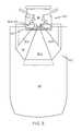
- FIG. 1is a top view and FIG. 2 is a perspective view of a material transport vehicle 100 that includes a bottom laser range scanner 110 and a laser range scanner 104 mounted near a top of the vehicle, in accordance with the prior art. Both of laser scanners 110 and 104 are used for safety.
- a mast 103can be part of or connected to vehicle 100.
- a light 102is mounted on the mast 103 to communicate signals to nearby individuals, such as signals used for warning and safety purposes.
- the laser scanner 104is also mounted on mast 103.
- Bottom laser scanner 110is mounted on a front portion of the vehicle 100 at a set height from a ground surface upon which the vehicle travels.
- the bottom laser scanner 110projects a laser beam in front of the vehicle 100 to define two zones, a safety zone 112 and a warning zone 114. If the bottom laser scanner detects a body or object (collectively "body”) in the safety zone 112 the scanner can send a signal to a controller (not shown) of the vehicle 110 which in turn communicates to the drive mechanisms (also not shown) of the vehicle 110. In response to receipt of a signal indicating detection of a body in the safety zone 112, the controller can cause the drive mechanisms to halt movement and/or operation of the vehicle. The controller can also cause light 102 to signal the presence of the condition. In this way, bottom laser scanner can be useful for providing safety relative to a body in front of the vehicle 100.
- the bottom laser scanner 110can send a signal to the controller.
- the controllerrather than halting operation, could cause the drive mechanism to slow operation and could cause the light 102 to communicate a warning signal. Such detections could also cause audible alarms to be activated.
- laser scanner 104Since the bottom laser scanner 110 projects parallel to the ground surface, objects beneath or above the plane are not detected.
- the use of laser scanner 104enables the safety zone to be extended to a third dimension, because the laser scanner 104 creates a scanning plane that projects from the laser scanner 104 to about a front edge of the safety zone 112, but also below the plane of the bottom laser scanner 110 to about the ground surface.
- the scanning plane produced by the laser scanner 104is referred to as a "light curtain" 116.
- laser scanner 104also communicates signals to the controller.
- the controllercan exercise an algorithm for causing the appropriate warning signals and drive mechanism control. For example, the controller can determine what to do if the laser scanner 104 detected a body momentarily, but the bottom scanner 110 never detected a body.
- vehicleincluding a multi-plane scanner support system as defined in claim 1.
- the systemincludes a scanner and a mirror block.
- the systemmay include a bracket configured to be secured in a fixed orientation with respect to a scanner; and the mirror block arranged to receive a scanning signal from the scanner and to reflect the scanning signal into a plurality of directions to create multiple scanning planes.
- the scanneris a laser range scanner.
- the mirror blockcan include a plurality of flat surface, each flat surface arranged to reflect the scanning signal to form a different one of the multiple scanning planes.
- the mirror blockcan include a contoured reflective surface configured to form a bent light curtain comprising the multiple scanning planes.
- the bracket and mirror blockcan be formed as a single unit.
- the mirror blockcan include a plurality of mirrors that receive the scanning signal.
- the plurality of mirrorscan include machined prisms.
- the vehicleincludes a controller operatively coupled to a drive mechanism.
- the multi-plane scanning systemincludes a laser range scanner coupled to the controller; a bracket configured to be secured in a fixed orientation with respect to the laser range scanner; and a mirror block arranged to receive a scanning signal from the laser range scanner and to reflect the scanning signal into a plurality of directions to create multiple scanning planes.
- the laser range scanneris configured to receive a signal from the multiple scanning planes, communicate the signal to the controller as a detection signal, and the controller modifies operation of the vehicle in response to the detection signal.
- the vehiclecan be an unmanned vehicle.
- the vehiclecan further include a bottom scanner that projects a safety zone and is also coupled to the controller, wherein the safety zone and at least one of the multiple planes intersect.
- spatially relative termssuch as “beneath,” “below,” “lower,” “above,” “upper” and the like may be used to describe an element and/or feature's relationship to another element(s) and/or feature(s) as, for example, illustrated in the figures. It will be understood that the spatially relative terms are intended to encompass different orientations of the device in use and/or operation in addition to the orientation depicted in the figures. For example, if the device in the figures is turned over, elements described as “below” and/or “beneath” other elements or features would then be oriented “above” the other elements or features. The device may be otherwise oriented (e.g., rotated 90 degrees or at other orientations) and the spatially relative descriptors used herein interpreted accordingly.
- FIG. 3shows a top view of a material transport vehicle 100 including multi-plane scanner support system 504 and scanner 104 in accordance with aspects of the present invention.
- FIG. 4provides a perspective view of the same arrangement.
- a bottom laser range scanner 110is includes that projects a safety zone 112 and a warning zone 114.
- a mast 103is included with a light mounted thereto.
- multi-plane scanner support system 504 and laser scanner 104are also mounted to mast 103.
- Vehicle 100includes a controller (not shown) to which laser scanner 104 and bottom laser scanner 110 are coupled. And the controller is coupled to a vehicle drive mechanism (not shown) that controls the operation of the vehicle. The controller is also coupled to light 102, as described with respect to FIGS. 1 and 2 previously described.
- the multi-plane scanner support systemis mounted relative to the scanner 104 such a light curtain 300 having multiple scanning planes 302, 304, and 306, is generated from the single laser 104. That is, typical lasers used scan a field of view of up to about 270 degrees.
- one or more reflective surfaces of the multi-plane scanner supportreceive the scanning signal in different portions of its scan to create multiple scanning planes 302, 304, and 306.
- a practical benefit of such an approach with material transport vehiclesis that it enables safety zone extension and detection to the front right and left areas of the vehicle. This can be extremely useful, for example, when an AGV is navigating around a corner - which are not covered by traditional safety zones and in FIGS. 1 and 2 .
- light curtain 300comprises three relatively discrete scanning planes 302, 304 and 306, but in other embodiments a contoured light curtain can be formed using a contoured multi-plane scanner support system 504.
- laser range scanneris a S100 laser range scanner by SICK, Inc. of Waldkirch, Germany.
- LSM100, S300, and S3000 modelsare other examples of a suitable laser range scanner, also by SICK, Inc.
- the laser scannerpoints about 34 degrees above horizontal and about 66 inches above the ground surface.
- the front plane 302has a field ground projection of about 1100 mm from the front of the vehicle 100 and the side planes 304, 306 have field ground projections of about 800mm from the center of the front of the vehicle 100. These are example, specific dimensions can differ depending, for example, on the vehicle.
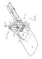
- FIGS. 5A-5Care different views of an embodiment of a laser range scanner and mirror system, in accordance with aspects of the present invention.
- Multi-plane scanner support system 504includes a bracket 510 that has the laser disposed therein, so that reflective surfaces attached to the bracket 510 reflect the laser beam of laser scanner 104 during operation.
- those reflective surfacesare comprised of three mirror blocks 512, 514, 516 attached to bracket 510.
- Each mirror blockincludes a reflective surface 513, 515, 517 that receives a scanning signal from the laser 104.
- Each of reflective surfaces 513, 515, 517is used to form a respective scanning plane.
- surface 513reflects the laser scanning beam along scanning plane 302
- reflective surface 515reflects the laser scanning beam along scanning plane 304
- reflective surface 517reflects the laser scanning beam along scanning plane 306 in FIGS. 3 and 4 .
- FIGS. 6Ais a perspective view of an embodiment of mirror block 512 and FIG. 6B is a perspective view of an embodiment of a bracket 510 of FIGS. 5A-5C .
- reflective surface 513(not shown in FIG. 6A ) would be attached to a surface A of mirror block 512.
- the reflective surfacecould take any of a variety of forms, such as a plate made from polished or machined metal or other material (e.g., glass).
- Mirror block 512is mounted to surface 510a of bracket 510, shown in FIG. 6B .
- mirror block 514would be mounted to surface 510b and mirror block 516 would be mounted to surface 510c.
- two or more of bracket 510, mirror blocks 512, 514, 516 and reflective surfaces 513, 515, 517can be made of a single material or compound.
- a contoured reflective surfacecould be used to form a bent light curtain, again having multiple planes. For example, concave curves, convex curve, bends, warps, prisms etc can be used to tailor the light curtain to have the desired number and shaped plurality of scanning planes.
- the present embodimentsachieve multiple planes without "nodding" mechanisms, are less expensive to make and maintain.
Landscapes
- Physics & Mathematics (AREA)
- Engineering & Computer Science (AREA)
- Electromagnetism (AREA)
- General Physics & Mathematics (AREA)
- Radar, Positioning & Navigation (AREA)
- Remote Sensing (AREA)
- Computer Networks & Wireless Communication (AREA)
- Automation & Control Theory (AREA)
- Aviation & Aerospace Engineering (AREA)
- Mechanical Engineering (AREA)
- Optics & Photonics (AREA)
- Multimedia (AREA)
- Mathematical Physics (AREA)
- Transportation (AREA)
- Optical Radar Systems And Details Thereof (AREA)
- Traffic Control Systems (AREA)
- Control Of Position, Course, Altitude, Or Attitude Of Moving Bodies (AREA)
Description
- The present inventive concepts relate to the field of safety scanning systems and vehicles using the same.
- Material transport vehicles and systems, such as fork lift trucks, tuggers, and the like, are used in a wide variety of applications. Such vehicles can include manned vehicles and automated guided vehicles (AGVs). Some such vehicles and systems can include sensors and scanners used for navigation and safety.
DE 197 57 848 discloses an apparatus for optical detection of objects and in particular of vehicles, within a monitored sector. The apparatus comprises a rotating pulsed transmitter emitting a collimated light beam, a receiver, and plane mirrors arranged such as to reflect the rotated beam in several planes within the observed sector.FIG. 1 is a top view andFIG. 2 is a perspective view of amaterial transport vehicle 100 that includes a bottomlaser range scanner 110 and alaser range scanner 104 mounted near a top of the vehicle, in accordance with the prior art. Both oflaser scanners - A
mast 103 can be part of or connected tovehicle 100. Alight 102 is mounted on themast 103 to communicate signals to nearby individuals, such as signals used for warning and safety purposes. Thelaser scanner 104 is also mounted onmast 103. Bottom laser scanner 110 is mounted on a front portion of thevehicle 100 at a set height from a ground surface upon which the vehicle travels. Thebottom laser scanner 110 projects a laser beam in front of thevehicle 100 to define two zones, asafety zone 112 and awarning zone 114. If the bottom laser scanner detects a body or object (collectively "body") in thesafety zone 112 the scanner can send a signal to a controller (not shown) of thevehicle 110 which in turn communicates to the drive mechanisms (also not shown) of thevehicle 110. In response to receipt of a signal indicating detection of a body in thesafety zone 112, the controller can cause the drive mechanisms to halt movement and/or operation of the vehicle. The controller can also causelight 102 to signal the presence of the condition. In this way, bottom laser scanner can be useful for providing safety relative to a body in front of thevehicle 100.- When a body detected in the
warning zone 114, thebottom laser scanner 110 can send a signal to the controller. The controller, rather than halting operation, could cause the drive mechanism to slow operation and could cause thelight 102 to communicate a warning signal. Such detections could also cause audible alarms to be activated. - Since the
bottom laser scanner 110 projects parallel to the ground surface, objects beneath or above the plane are not detected. The use oflaser scanner 104 enables the safety zone to be extended to a third dimension, because thelaser scanner 104 creates a scanning plane that projects from thelaser scanner 104 to about a front edge of thesafety zone 112, but also below the plane of thebottom laser scanner 110 to about the ground surface. The scanning plane produced by thelaser scanner 104 is referred to as a "light curtain" 116. Likebottom scanner 110,laser scanner 104 also communicates signals to the controller. The controller can exercise an algorithm for causing the appropriate warning signals and drive mechanism control. For example, the controller can determine what to do if thelaser scanner 104 detected a body momentarily, but thebottom scanner 110 never detected a body. - In accordance with one aspect of the present disclosure, provided is vehicle including a multi-plane scanner support system as defined in claim 1. The system includes a scanner and a mirror block. The system may include a bracket configured to be secured in a fixed orientation with respect to a scanner; and the mirror block arranged to receive a scanning signal from the scanner and to reflect the scanning signal into a plurality of directions to create multiple scanning planes.
- The scanner is a laser range scanner.
- The mirror block can include a plurality of flat surface, each flat surface arranged to reflect the scanning signal to form a different one of the multiple scanning planes.
- The mirror block can include a contoured reflective surface configured to form a bent light curtain comprising the multiple scanning planes.
- The bracket and mirror block can be formed as a single unit.
- The mirror block can include a plurality of mirrors that receive the scanning signal.
- The plurality of mirrors can include machined prisms.
- In an embodiment the vehicle includes a controller operatively coupled to a drive mechanism. The multi-plane scanning system includes a laser range scanner coupled to the controller; a bracket configured to be secured in a fixed orientation with respect to the laser range scanner; and a mirror block arranged to receive a scanning signal from the laser range scanner and to reflect the scanning signal into a plurality of directions to create multiple scanning planes. The laser range scanner is configured to receive a signal from the multiple scanning planes, communicate the signal to the controller as a detection signal, and the controller modifies operation of the vehicle in response to the detection signal.
- The vehicle can be an unmanned vehicle.
- The vehicle can further include a bottom scanner that projects a safety zone and is also coupled to the controller, wherein the safety zone and at least one of the multiple planes intersect.
- The present invention will become more apparent in view of the attached drawings and accompanying detailed description. The embodiments depicted therein are provided by way of example, not by way of limitation, wherein like reference numerals refer to the same or similar elements. The drawings are not necessarily to scale, emphasis instead being placed upon illustrating aspects of the invention. In the drawings:
FIG. 1 is a top view of a material transport vehicle with a prior art laser range scanner system, in accordance with the prior art;FIG. 2 is a perspective view of the prior art system ofFIG. 1 ;FIG. 3 is a top view of a material transport vehicle with an embodiment of a multi-plane laser range scanner system, in accordance with the present invention;FIG. 4 is a perspective view of the system ofFIG. 2 , in accordance with aspects of the present invention;FIGS. 5A-5C are different views of an embodiment of a laser range scanner and mirror system, in accordance with aspects of the present invention;FIGS. 6A is a perspective view of an embodiment of a mirror block, in accordance with aspects of the present invention; andFIG. 6B is a perspective view of an embodiment of a bracket that can be used to support the mirror block ofFIG. 6A , in accordance with aspects of the present invention.- Hereinafter, aspects of the present invention will be described by explaining illustrative embodiments in accordance therewith, with reference to the attached drawings. While describing these embodiments, detailed descriptions of well-known items, functions, or configurations are typically omitted for conciseness.
- It will be understood that, although the terms first, second, etc. are be used herein to describe various elements, these elements should not be limited by these terms. These terms are used to distinguish one element from another, but not to imply a required sequence of elements. For example, a first element can be termed a second element, and, similarly, a second element can be termed a first element, without departing from the scope of the present invention. As used herein, the term "and/or" includes any and all combinations of one or more of the associated listed items.
- It will be understood that when an element is referred to as being "on" or "connected" or "coupled" to another element, it can be directly on or connected or coupled to the other element or intervening elements can be present. In contrast, when an element is referred to as being "directly on" or "directly connected" or "directly coupled" to another element, there are no intervening elements present. Other words used to describe the relationship between elements should be interpreted in a like fashion (e.g., "between" versus "directly between," "adjacent" versus "directly adjacent," etc.).
- The terminology used herein is for the purpose of describing particular embodiments only and is not intended to be limiting of the invention. As used herein, the singular forms "a," "an" and "the" are intended to include the plural forms as well, unless the context clearly indicates otherwise. It will be further understood that the terms "comprises," "comprising," "includes" and/or "including," when used herein, specify the presence of stated features, steps, operations, elements, and/or components, but do not preclude the presence or addition of one or more other features, steps, operations, elements, components, and/or groups thereof.
- Spatially relative terms, such as "beneath," "below," "lower," "above," "upper" and the like may be used to describe an element and/or feature's relationship to another element(s) and/or feature(s) as, for example, illustrated in the figures. It will be understood that the spatially relative terms are intended to encompass different orientations of the device in use and/or operation in addition to the orientation depicted in the figures. For example, if the device in the figures is turned over, elements described as "below" and/or "beneath" other elements or features would then be oriented "above" the other elements or features. The device may be otherwise oriented (e.g., rotated 90 degrees or at other orientations) and the spatially relative descriptors used herein interpreted accordingly.
FIG. 3 shows a top view of amaterial transport vehicle 100 including multi-plane scanner support system 504 andscanner 104 in accordance with aspects of the present invention.FIG. 4 provides a perspective view of the same arrangement. As inFIGS. 1 and2 , a bottomlaser range scanner 110 is includes that projects asafety zone 112 and awarning zone 114. And amast 103 is included with a light mounted thereto.- In this embodiment, multi-plane scanner support system 504 and
laser scanner 104 are also mounted tomast 103.Vehicle 100 includes a controller (not shown) to whichlaser scanner 104 andbottom laser scanner 110 are coupled. And the controller is coupled to a vehicle drive mechanism (not shown) that controls the operation of the vehicle. The controller is also coupled tolight 102, as described with respect toFIGS. 1 and2 previously described. - Unlike the prior art, the multi-plane scanner support system is mounted relative to the
scanner 104 such alight curtain 300 having multiple scanningplanes single laser 104. That is, typical lasers used scan a field of view of up to about 270 degrees. In the present invention, one or more reflective surfaces of the multi-plane scanner support receive the scanning signal in different portions of its scan to createmultiple scanning planes FIGS. 1 and2 . - In
FIG. 3 ,light curtain 300 comprises three relatively discrete scanning planes 302, 304 and 306, but in other embodiments a contoured light curtain can be formed using a contoured multi-plane scanner support system 504. - In the illustrative embodiment, laser range scanner is a S100 laser range scanner by SICK, Inc. of Waldkirch, Germany. Although the LSM100, S300, and S3000 models are other examples of a suitable laser range scanner, also by SICK, Inc. The laser scanner points about 34 degrees above horizontal and about 66 inches above the ground surface. The
front plane 302 has a field ground projection of about 1100 mm from the front of thevehicle 100 and the side planes 304, 306 have field ground projections of about 800mm from the center of the front of thevehicle 100. These are example, specific dimensions can differ depending, for example, on the vehicle. FIGS. 5A-5C are different views of an embodiment of a laser range scanner and mirror system, in accordance with aspects of the present invention;- In
FIGS. 5A-5C an embodiment ofscanning system 500 is shown that uses multi-plane scanner support system 504 andscanner 104 attached tomast 103, as discussed above. Multi-plane scanner support system 504 includes abracket 510 that has the laser disposed therein, so that reflective surfaces attached to thebracket 510 reflect the laser beam oflaser scanner 104 during operation. In this embodiment, those reflective surfaces are comprised of threemirror blocks bracket 510. Each mirror block includes areflective surface laser 104. Each ofreflective surfaces surface 513 reflects the laser scanning beam alongscanning plane 302,reflective surface 515 reflects the laser scanning beam alongscanning plane 304, andreflective surface 517 reflects the laser scanning beam alongscanning plane 306 inFIGS. 3 and4 . FIGS. 6A is a perspective view of an embodiment ofmirror block 512 andFIG. 6B is a perspective view of an embodiment of abracket 510 ofFIGS. 5A-5C . In this embodiment, reflective surface 513 (not shown inFIG. 6A ) would be attached to a surface A ofmirror block 512. The reflective surface could take any of a variety of forms, such as a plate made from polished or machined metal or other material (e.g., glass).Mirror block 512 is mounted tosurface 510a ofbracket 510, shown inFIG. 6B . Similarly,mirror block 514 would be mounted tosurface 510b and mirror block 516 would be mounted tosurface 510c.- In some embodiments, two or more of
bracket 510, mirror blocks 512, 514, 516 andreflective surfaces - The present embodiments achieve multiple planes without "nodding" mechanisms, are less expensive to make and maintain.
- While the foregoing has described what are considered to be the best mode and/or other preferred embodiments, it is understood that various modifications can be made therein and that the invention or inventions may be implemented in various forms and embodiments, and that they may be applied in numerous applications, only some of which have been described herein. It is intended by the following claims to claim that which is literally described and all equivalents thereto, including all modifications and variations that fall within the scope of each claim.
Claims (13)
- A vehicle having a multi-plane scanning system (500), comprising:a bottom laser scanner (110), which projects a horizontal scanning plane in front of the vehicle and parallel to a ground surface to define a safety zone (112);a laser range scanner (104) mounted near a top of the vehicle; anda mirror block (512, 514, 516) comprising a plurality of reflective surfaces (513, 515. 517) and arranged to receive a scanning signal from the laser range scanner (104) and to reflect the scanning signal to generate a light curtain (300) having multiple scanning planes (302, 304, 306) downwardly projecting toward the ground surface to extend the safety zone (112) to a third dimension, wherein the multiple scanning planes include a scanning plane projecting to the front edge of the safety zone, a scanning plane projecting to the right side of the safety zone and a scanning plane projecting to the left side of the safety zone.
- The vehicle (100) of claim 1, wherein the mirror block includes a plurality of flat surfaces, each flat surface arranged to reflect the scanning signal to form a different one of the multiple scanning planes.
- The vehicle (100) of claim 1, wherein the mirror block includes a contoured reflective surface configured to form a bent light curtain comprising the multiple scanning planes.
- The vehicle (100) of claim 1, further comprising a bracket (510) configured to couple the mirror block (512, 514, 516) in a fixed orientation with respect to the laser range scanner (104).
- The vehicle (100) of claim 1, wherein the mirror block includes a plurality of mirrors (513, 515, 517) that receive the scanning signal.
- The vehicle (100) of claim 5, wherein the plurality of mirrors (513, 515, 517) includes machined prisms.
- The vehicle (100) of claim 1, further comprising:a controller operatively coupled to a drive mechanism;wherein the laser range scanner (104) is coupled to the controller;and whereinthe laser range scanner (104) is configured to receive a signal from the multiple scanning planes (302, 304, 306), communicate the signal to the controller as a detection signal, and the controller modifies operation of the vehicle (100) in response to the detection signal.
- The vehicle (100) of claim 7, wherein the vehicle is an unmanned vehicle.
- The vehicle (100) of claim 8, wherein the vehicle is a material transport vehicle.
- The vehicle (100) of claim 1, wherein the light curtain (300) comprises three relatively discrete scanning planes (302, 304, 306)
- The vehicle (100) of claim 1, wherein the light curtain (300) is a contoured light curtain.
- The vehicle (100) of claim 1, wherein the laser range scanner (104) points about 34 degrees above horizontal and about 66 inches above the ground surface.
- The vehicle (100) of claim 1, wherein the scanning plane (302) protecting to the front edge of the safety zone has a field ground projection of about 1100 mm from the front of the vehicle (100) and scanning planes (304, 306) projecting to the left and right side of the safety zone have field ground projections of about 800 mm from the center of the front of the vehicle (100).
Applications Claiming Priority (2)
| Application Number | Priority Date | Filing Date | Title |
|---|---|---|---|
| US12/542,279US8169596B2 (en) | 2009-08-17 | 2009-08-17 | System and method using a multi-plane curtain |
| PCT/US2010/045451WO2011022303A2 (en) | 2009-08-17 | 2010-08-13 | System and method using a multi-plane curtain |
Publications (3)
| Publication Number | Publication Date |
|---|---|
| EP2467280A2 EP2467280A2 (en) | 2012-06-27 |
| EP2467280A4 EP2467280A4 (en) | 2012-11-14 |
| EP2467280B1true EP2467280B1 (en) | 2014-11-05 |
Family
ID=43588415
Family Applications (1)
| Application Number | Title | Priority Date | Filing Date |
|---|---|---|---|
| EP10810425.8AActiveEP2467280B1 (en) | 2009-08-17 | 2010-08-13 | System and method using a multi-plane curtain |
Country Status (6)
| Country | Link |
|---|---|
| US (3) | US8169596B2 (en) |
| EP (1) | EP2467280B1 (en) |
| KR (1) | KR101328484B1 (en) |
| CN (1) | CN102648112B (en) |
| CA (1) | CA2807721C (en) |
| WO (1) | WO2011022303A2 (en) |
Families Citing this family (34)
| Publication number | Priority date | Publication date | Assignee | Title |
|---|---|---|---|---|
| US8169596B2 (en) | 2009-08-17 | 2012-05-01 | Seegrid Corporation | System and method using a multi-plane curtain |
| JP2012236244A (en)* | 2011-05-10 | 2012-12-06 | Sony Corp | Robot device, method of controlling the same, and program for controlling the same |
| US9181048B1 (en)* | 2011-12-30 | 2015-11-10 | The Rosemyr Corporation | Portable storage container system |
| WO2013112907A1 (en) | 2012-01-25 | 2013-08-01 | Adept Technology, Inc. | Autonomous mobile robot for handling job assignments in a physical environment inhabited by stationary and non-stationary obstacles |
| ES2827192T3 (en) | 2012-02-08 | 2021-05-20 | Omron Tateisi Electronics Co | Task management system for a fleet of autonomous mobile robots |
| JP6255724B2 (en)* | 2013-06-10 | 2018-01-10 | セイコーエプソン株式会社 | Robot and robot operation method |
| KR101551667B1 (en)* | 2013-11-27 | 2015-09-09 | 현대모비스(주) | LIDAR Sensor System |
| US9567102B1 (en)* | 2014-01-29 | 2017-02-14 | Stan W. Ross | Safety system with projectable warning indicia |
| CN104142138B (en)* | 2014-07-15 | 2016-08-24 | 华东建筑设计研究院有限公司 | scanner auxiliary device |
| JP6527941B2 (en)* | 2015-03-23 | 2019-06-12 | 株式会社Fuji | Moving body |
| DE102015105560A1 (en)* | 2015-04-13 | 2016-10-13 | Hamburg Innovation Gmbh | Sensor device with optoelectronic sensor and measuring range extension |
| JP6542574B2 (en)* | 2015-05-12 | 2019-07-10 | 株式会社豊田中央研究所 | forklift |
| CN105606023A (en)* | 2015-12-18 | 2016-05-25 | 武汉万集信息技术有限公司 | Vehicle profile dimensions measuring method and system |
| DE102015226771A1 (en)* | 2015-12-29 | 2017-06-29 | Robert Bosch Gmbh | Deflection device for a lidar sensor |
| JP6754594B2 (en)* | 2016-03-23 | 2020-09-16 | 株式会社小松製作所 | Motor grader |
| EP3269678B1 (en) | 2016-07-14 | 2019-03-06 | Toyota Material Handling Manufacturing Sweden AB | Floor conveyor |
| EP3269680B1 (en)* | 2016-07-14 | 2020-09-30 | Toyota Material Handling Manufacturing Sweden AB | Floor conveyor |
| EP3269679B2 (en)* | 2016-07-14 | 2024-12-04 | Toyota Material Handling Manufacturing Sweden AB | Floor conveyor |
| KR102231883B1 (en)* | 2016-08-26 | 2021-03-29 | 크라운 이큅먼트 코포레이션 | Multi-field scanning tools for material handling vehicles |
| WO2018039559A2 (en) | 2016-08-26 | 2018-03-01 | Crown Equipment Corporation | Materials handling vehicle obstacle scanning tools |
| KR102402134B1 (en)* | 2016-08-26 | 2022-05-30 | 크라운 이큅먼트 코포레이션 | Material Handling Vehicle Path Validation and Dynamic Path Correction |
| WO2018182812A2 (en)* | 2016-12-30 | 2018-10-04 | Innovusion Ireland Limited | Multiwavelength lidar design |
| US11474254B2 (en) | 2017-11-07 | 2022-10-18 | Piaggio Fast Forward Inc. | Multi-axes scanning system from single-axis scanner |
| CN110376601B (en)* | 2018-08-14 | 2022-08-12 | 北京京东乾石科技有限公司 | Method and system for determining target pose |
| FR3091525B1 (en) | 2019-01-04 | 2021-01-29 | Balyo | Self-guided handling equipment incorporating detection means |
| US11840436B2 (en) | 2019-04-02 | 2023-12-12 | The Raymond Corporation | Mast and supplementary object detection system for a material handling vehicle |
| CN110515046A (en)* | 2019-07-29 | 2019-11-29 | 上海卫星装备研究所 | Satellite SAR antenna TR channel width phase check device and its operating method |
| WO2021183605A1 (en) | 2020-03-10 | 2021-09-16 | Seegrid Corporation | Self-driving vehicle path adaptation system and method |
| CN112158705B (en)* | 2020-08-31 | 2021-06-29 | 猫岐智能科技(上海)有限公司 | Light curtain imaging method and system, light curtain identification method and system, light curtain device and elevator equipment |
| US20230023551A1 (en)* | 2021-07-20 | 2023-01-26 | Murata Machinery, Ltd. | Autonomous traveling body |
| WO2023066472A1 (en) | 2021-10-19 | 2023-04-27 | Abb Schweiz Ag | Robotic system comprising an environment sensor |
| USD1013000S1 (en) | 2022-03-25 | 2024-01-30 | Seegrid Corporation | Mobile robot |
| WO2024070180A1 (en)* | 2022-09-27 | 2024-04-04 | オプテックス株式会社 | Scan sensor |
| US12292535B2 (en) | 2022-11-08 | 2025-05-06 | Seegrid Corporation | Method and system for calibrating a light-curtain |
Family Cites Families (28)
| Publication number | Priority date | Publication date | Assignee | Title |
|---|---|---|---|---|
| DE2532602C3 (en)* | 1975-07-21 | 1979-07-05 | Erwin Sick Gmbh Optik-Elektronik, 7808 Waldkirch | Optical device with a light curtain |
| JPS5596475A (en)* | 1979-01-19 | 1980-07-22 | Nissan Motor Co Ltd | Obstacle detector for vehicle |
| DE3635271C1 (en)* | 1986-10-16 | 1987-10-29 | Sick Optik Elektronik Erwin | Light curtain device |
| DE3707978C1 (en)* | 1987-03-12 | 1988-03-17 | Sick Optik Elektronik Erwin | Light curtain |
| US5805275A (en)* | 1993-04-08 | 1998-09-08 | Kollmorgen Corporation | Scanning optical rangefinder |
| US7359782B2 (en)* | 1994-05-23 | 2008-04-15 | Automotive Technologies International, Inc. | Vehicular impact reactive system and method |
| FR2724464B1 (en)* | 1994-09-13 | 1996-11-22 | Matra Marconi Space France | ON-BOARD DEVICE FOR MEASURING LIGHT BACK BROADCAST |
| DE19530281C2 (en)* | 1995-08-17 | 1999-01-07 | Johann Hipp | Device for optically detecting obstacles in front of vehicles |
| US6141105A (en)* | 1995-11-17 | 2000-10-31 | Minolta Co., Ltd. | Three-dimensional measuring device and three-dimensional measuring method |
| US7983802B2 (en)* | 1997-10-22 | 2011-07-19 | Intelligent Technologies International, Inc. | Vehicular environment scanning techniques |
| DE19757848C2 (en)* | 1997-12-24 | 2003-04-30 | Sick Ag | Device for the optical detection of objects |
| US6252659B1 (en)* | 1998-03-26 | 2001-06-26 | Minolta Co., Ltd. | Three dimensional measurement apparatus |
| US6429941B1 (en)* | 1998-07-14 | 2002-08-06 | Minolta Co., Ltd. | Distance measuring equipment and method |
| JP2000147124A (en)* | 1998-11-12 | 2000-05-26 | Denso Corp | On-vehicle radar device |
| US6710325B2 (en)* | 2001-12-20 | 2004-03-23 | Dynapar Corporation | Light curtain mounting system wherein housing and mounting bracket include curved surfaces |
| KR100470147B1 (en)* | 2002-07-13 | 2005-02-05 | 지오텍컨설탄트 주식회사 | Method for Three-Dimensional Surveying System and Inferring Orientation of Rock-mass Joints Using Reference Coordinate and Laser-Scanner |
| US7076366B2 (en)* | 2002-09-06 | 2006-07-11 | Steven Simon | Object collision avoidance system for a vehicle |
| US6985212B2 (en)* | 2003-05-19 | 2006-01-10 | Rosemount Aerospace Inc. | Laser perimeter awareness system |
| JP3941795B2 (en)* | 2004-04-28 | 2007-07-04 | 株式会社デンソー | Leading vehicle recognition device |
| EP1612509A1 (en)* | 2004-07-01 | 2006-01-04 | Sick IVP AB | Optical profilometer |
| DE102004047022A1 (en)* | 2004-09-28 | 2006-04-06 | Siemens Ag | Device for monitoring room areas |
| JP4883517B2 (en)* | 2004-11-19 | 2012-02-22 | 学校法人福岡工業大学 | Three-dimensional measuring apparatus, three-dimensional measuring method, and three-dimensional measuring program |
| US20090184811A1 (en)* | 2008-01-23 | 2009-07-23 | Althoff Nicholas K | Methods and system for an impact avoidance system |
| US7947944B2 (en)* | 2008-11-03 | 2011-05-24 | Trimble Navigation Limited | Laser transmitter, laser receiver and method |
| US8169596B2 (en) | 2009-08-17 | 2012-05-01 | Seegrid Corporation | System and method using a multi-plane curtain |
| JP5637995B2 (en)* | 2009-10-30 | 2014-12-10 | 株式会社オプトエレクトロニクス | Optical information reader |
| WO2013123600A1 (en)* | 2012-02-21 | 2013-08-29 | Flow-Rite Safety Solutions Inc. | Warning device and collision avoidance system |
| JP6132659B2 (en)* | 2013-02-27 | 2017-05-24 | シャープ株式会社 | Ambient environment recognition device, autonomous mobile system using the same, and ambient environment recognition method |
- 2009
- 2009-08-17USUS12/542,279patent/US8169596B2/enactiveActive
- 2010
- 2010-08-13CNCN201080036411.6Apatent/CN102648112B/ennot_activeExpired - Fee Related
- 2010-08-13WOPCT/US2010/045451patent/WO2011022303A2/enactiveApplication Filing
- 2010-08-13KRKR1020127006927Apatent/KR101328484B1/ennot_activeExpired - Fee Related
- 2010-08-13CACA2807721Apatent/CA2807721C/enactiveActive
- 2010-08-13EPEP10810425.8Apatent/EP2467280B1/enactiveActive
- 2012
- 2012-04-30USUS13/460,096patent/US9310608B2/enactiveActive
- 2016
- 2016-04-12USUS15/096,748patent/US9910137B2/enactiveActive
Also Published As
| Publication number | Publication date |
|---|---|
| WO2011022303A2 (en) | 2011-02-24 |
| EP2467280A4 (en) | 2012-11-14 |
| EP2467280A2 (en) | 2012-06-27 |
| US20120218538A1 (en) | 2012-08-30 |
| KR20120062785A (en) | 2012-06-14 |
| CN102648112B (en) | 2015-01-28 |
| US8169596B2 (en) | 2012-05-01 |
| US9310608B2 (en) | 2016-04-12 |
| CA2807721C (en) | 2017-11-07 |
| CN102648112A (en) | 2012-08-22 |
| HK1172589A1 (en) | 2013-04-26 |
| KR101328484B1 (en) | 2013-11-13 |
| WO2011022303A3 (en) | 2011-06-23 |
| CA2807721A1 (en) | 2011-02-24 |
| US9910137B2 (en) | 2018-03-06 |
| US20110037963A1 (en) | 2011-02-17 |
| US20160223655A1 (en) | 2016-08-04 |
Similar Documents
| Publication | Publication Date | Title |
|---|---|---|
| EP2467280B1 (en) | System and method using a multi-plane curtain | |
| US11669101B1 (en) | Light steering device with an array of oscillating reflective slats | |
| US20160188977A1 (en) | Mobile Security Robot | |
| JP2019507326A (en) | LIDAR scanning device for use in automobiles | |
| US10401865B1 (en) | Light steering device with an array of oscillating reflective slats | |
| JP7227391B2 (en) | Method and system for detecting obstacles in sensor housing | |
| KR102179238B1 (en) | Human following cruise and autonomous method for a vehicle | |
| KR960703760A (en) | PROCESS FOR TREATING AN OBJECT, IN PARTICULAR AN AEROPLANE | |
| EP4049964A1 (en) | Industrial vehicle | |
| JP2023539790A (en) | Dual shaft axial flux motor for optical scanners | |
| JP2022523193A (en) | Methods and systems for detecting degraded LIDAR range measurement accuracy | |
| US11474254B2 (en) | Multi-axes scanning system from single-axis scanner | |
| CN113167904A (en) | Object detection device | |
| KR101737535B1 (en) | A improved laser range finder device | |
| US20220100192A1 (en) | Self-guided handling apparatus comprising a detection means | |
| CN115145273B (en) | Obstacle avoidance control method, robot and computer readable storage medium | |
| KR20170087006A (en) | Omnidirectional obstacle detection apparatus, autonomous driving robot using it and omnidirectional obstacle detection method of autonomous driving robot | |
| HK1172589B (en) | System and method using a multi-plane curtain | |
| JP2006247803A (en) | Autonomous mobile robot | |
| KR20240158833A (en) | Glass walls and doors detection and distance measuring for robots and method of controlling the same | |
| US12436536B1 (en) | Light steering device with a plurality of beam-steering optics | |
| WO2025080642A1 (en) | Autonomous mobile robot systems | |
| Nimesh et al. | Collision Avoidance System for Mobile Robots |
Legal Events
| Date | Code | Title | Description |
|---|---|---|---|
| PUAI | Public reference made under article 153(3) epc to a published international application that has entered the european phase | Free format text:ORIGINAL CODE: 0009012 | |
| 17P | Request for examination filed | Effective date:20120316 | |
| AK | Designated contracting states | Kind code of ref document:A2 Designated state(s):AL AT BE BG CH CY CZ DE DK EE ES FI FR GB GR HR HU IE IS IT LI LT LU LV MC MK MT NL NO PL PT RO SE SI SK SM TR | |
| A4 | Supplementary search report drawn up and despatched | Effective date:20121012 | |
| RIC1 | Information provided on ipc code assigned before grant | Ipc:G01S 7/481 20060101AFI20121008BHEP Ipc:G05D 1/02 20060101ALI20121008BHEP Ipc:G02B 26/10 20060101ALI20121008BHEP | |
| DAX | Request for extension of the european patent (deleted) | ||
| 17Q | First examination report despatched | Effective date:20130611 | |
| REG | Reference to a national code | Ref country code:DE Ref legal event code:R079 Ref document number:602010020029 Country of ref document:DE Free format text:PREVIOUS MAIN CLASS: B60R0001000000 Ipc:G01S0007481000 | |
| GRAP | Despatch of communication of intention to grant a patent | Free format text:ORIGINAL CODE: EPIDOSNIGR1 | |
| INTG | Intention to grant announced | Effective date:20140616 | |
| RIC1 | Information provided on ipc code assigned before grant | Ipc:G01S 17/87 20060101ALI20140602BHEP Ipc:G02B 26/10 20060101ALI20140602BHEP Ipc:G01S 7/481 20060101AFI20140602BHEP Ipc:G01S 17/42 20060101ALI20140602BHEP Ipc:G05D 1/02 20060101ALI20140602BHEP | |
| GRAS | Grant fee paid | Free format text:ORIGINAL CODE: EPIDOSNIGR3 | |
| GRAA | (expected) grant | Free format text:ORIGINAL CODE: 0009210 | |
| AK | Designated contracting states | Kind code of ref document:B1 Designated state(s):AL AT BE BG CH CY CZ DE DK EE ES FI FR GB GR HR HU IE IS IT LI LT LU LV MC MK MT NL NO PL PT RO SE SI SK SM TR | |
| REG | Reference to a national code | Ref country code:GB Ref legal event code:FG4D | |
| REG | Reference to a national code | Ref country code:CH Ref legal event code:EP | |
| REG | Reference to a national code | Ref country code:AT Ref legal event code:REF Ref document number:694900 Country of ref document:AT Kind code of ref document:T Effective date:20141115 | |
| REG | Reference to a national code | Ref country code:IE Ref legal event code:FG4D | |
| REG | Reference to a national code | Ref country code:DE Ref legal event code:R096 Ref document number:602010020029 Country of ref document:DE Effective date:20141218 | |
| REG | Reference to a national code | Ref country code:SE Ref legal event code:TRGR | |
| REG | Reference to a national code | Ref country code:AT Ref legal event code:MK05 Ref document number:694900 Country of ref document:AT Kind code of ref document:T Effective date:20141105 | |
| REG | Reference to a national code | Ref country code:NL Ref legal event code:VDEP Effective date:20141105 | |
| REG | Reference to a national code | Ref country code:LT Ref legal event code:MG4D | |
| PG25 | Lapsed in a contracting state [announced via postgrant information from national office to epo] | Ref country code:NL Free format text:LAPSE BECAUSE OF FAILURE TO SUBMIT A TRANSLATION OF THE DESCRIPTION OR TO PAY THE FEE WITHIN THE PRESCRIBED TIME-LIMIT Effective date:20141105 Ref country code:ES Free format text:LAPSE BECAUSE OF FAILURE TO SUBMIT A TRANSLATION OF THE DESCRIPTION OR TO PAY THE FEE WITHIN THE PRESCRIBED TIME-LIMIT Effective date:20141105 Ref country code:LT Free format text:LAPSE BECAUSE OF FAILURE TO SUBMIT A TRANSLATION OF THE DESCRIPTION OR TO PAY THE FEE WITHIN THE PRESCRIBED TIME-LIMIT Effective date:20141105 Ref country code:PT Free format text:LAPSE BECAUSE OF FAILURE TO SUBMIT A TRANSLATION OF THE DESCRIPTION OR TO PAY THE FEE WITHIN THE PRESCRIBED TIME-LIMIT Effective date:20150305 Ref country code:IS Free format text:LAPSE BECAUSE OF FAILURE TO SUBMIT A TRANSLATION OF THE DESCRIPTION OR TO PAY THE FEE WITHIN THE PRESCRIBED TIME-LIMIT Effective date:20150305 Ref country code:NO Free format text:LAPSE BECAUSE OF FAILURE TO SUBMIT A TRANSLATION OF THE DESCRIPTION OR TO PAY THE FEE WITHIN THE PRESCRIBED TIME-LIMIT Effective date:20150205 | |
| PG25 | Lapsed in a contracting state [announced via postgrant information from national office to epo] | Ref country code:LV Free format text:LAPSE BECAUSE OF FAILURE TO SUBMIT A TRANSLATION OF THE DESCRIPTION OR TO PAY THE FEE WITHIN THE PRESCRIBED TIME-LIMIT Effective date:20141105 Ref country code:PL Free format text:LAPSE BECAUSE OF FAILURE TO SUBMIT A TRANSLATION OF THE DESCRIPTION OR TO PAY THE FEE WITHIN THE PRESCRIBED TIME-LIMIT Effective date:20141105 Ref country code:HR Free format text:LAPSE BECAUSE OF FAILURE TO SUBMIT A TRANSLATION OF THE DESCRIPTION OR TO PAY THE FEE WITHIN THE PRESCRIBED TIME-LIMIT Effective date:20141105 Ref country code:AT Free format text:LAPSE BECAUSE OF FAILURE TO SUBMIT A TRANSLATION OF THE DESCRIPTION OR TO PAY THE FEE WITHIN THE PRESCRIBED TIME-LIMIT Effective date:20141105 Ref country code:CY Free format text:LAPSE BECAUSE OF FAILURE TO SUBMIT A TRANSLATION OF THE DESCRIPTION OR TO PAY THE FEE WITHIN THE PRESCRIBED TIME-LIMIT Effective date:20141105 Ref country code:GR Free format text:LAPSE BECAUSE OF FAILURE TO SUBMIT A TRANSLATION OF THE DESCRIPTION OR TO PAY THE FEE WITHIN THE PRESCRIBED TIME-LIMIT Effective date:20150206 | |
| REG | Reference to a national code | Ref country code:HK Ref legal event code:GR Ref document number:1172589 Country of ref document:HK | |
| PG25 | Lapsed in a contracting state [announced via postgrant information from national office to epo] | Ref country code:DK Free format text:LAPSE BECAUSE OF FAILURE TO SUBMIT A TRANSLATION OF THE DESCRIPTION OR TO PAY THE FEE WITHIN THE PRESCRIBED TIME-LIMIT Effective date:20141105 Ref country code:CZ Free format text:LAPSE BECAUSE OF FAILURE TO SUBMIT A TRANSLATION OF THE DESCRIPTION OR TO PAY THE FEE WITHIN THE PRESCRIBED TIME-LIMIT Effective date:20141105 Ref country code:EE Free format text:LAPSE BECAUSE OF FAILURE TO SUBMIT A TRANSLATION OF THE DESCRIPTION OR TO PAY THE FEE WITHIN THE PRESCRIBED TIME-LIMIT Effective date:20141105 Ref country code:SK Free format text:LAPSE BECAUSE OF FAILURE TO SUBMIT A TRANSLATION OF THE DESCRIPTION OR TO PAY THE FEE WITHIN THE PRESCRIBED TIME-LIMIT Effective date:20141105 | |
| REG | Reference to a national code | Ref country code:DE Ref legal event code:R097 Ref document number:602010020029 Country of ref document:DE | |
| PLBE | No opposition filed within time limit | Free format text:ORIGINAL CODE: 0009261 | |
| STAA | Information on the status of an ep patent application or granted ep patent | Free format text:STATUS: NO OPPOSITION FILED WITHIN TIME LIMIT | |
| 26N | No opposition filed | Effective date:20150806 | |
| PG25 | Lapsed in a contracting state [announced via postgrant information from national office to epo] | Ref country code:SI Free format text:LAPSE BECAUSE OF FAILURE TO SUBMIT A TRANSLATION OF THE DESCRIPTION OR TO PAY THE FEE WITHIN THE PRESCRIBED TIME-LIMIT Effective date:20141105 | |
| PG25 | Lapsed in a contracting state [announced via postgrant information from national office to epo] | Ref country code:LU Free format text:LAPSE BECAUSE OF FAILURE TO SUBMIT A TRANSLATION OF THE DESCRIPTION OR TO PAY THE FEE WITHIN THE PRESCRIBED TIME-LIMIT Effective date:20150813 Ref country code:MC Free format text:LAPSE BECAUSE OF FAILURE TO SUBMIT A TRANSLATION OF THE DESCRIPTION OR TO PAY THE FEE WITHIN THE PRESCRIBED TIME-LIMIT Effective date:20141105 | |
| REG | Reference to a national code | Ref country code:CH Ref legal event code:PL | |
| PG25 | Lapsed in a contracting state [announced via postgrant information from national office to epo] | Ref country code:CH Free format text:LAPSE BECAUSE OF NON-PAYMENT OF DUE FEES Effective date:20150831 Ref country code:LI Free format text:LAPSE BECAUSE OF NON-PAYMENT OF DUE FEES Effective date:20150831 | |
| PG25 | Lapsed in a contracting state [announced via postgrant information from national office to epo] | Ref country code:RO Free format text:LAPSE BECAUSE OF FAILURE TO SUBMIT A TRANSLATION OF THE DESCRIPTION OR TO PAY THE FEE WITHIN THE PRESCRIBED TIME-LIMIT Effective date:20141105 | |
| REG | Reference to a national code | Ref country code:IE Ref legal event code:MM4A | |
| PG25 | Lapsed in a contracting state [announced via postgrant information from national office to epo] | Ref country code:IE Free format text:LAPSE BECAUSE OF NON-PAYMENT OF DUE FEES Effective date:20150813 | |
| REG | Reference to a national code | Ref country code:FR Ref legal event code:PLFP Year of fee payment:7 | |
| PG25 | Lapsed in a contracting state [announced via postgrant information from national office to epo] | Ref country code:MT Free format text:LAPSE BECAUSE OF FAILURE TO SUBMIT A TRANSLATION OF THE DESCRIPTION OR TO PAY THE FEE WITHIN THE PRESCRIBED TIME-LIMIT Effective date:20141105 | |
| PG25 | Lapsed in a contracting state [announced via postgrant information from national office to epo] | Ref country code:HU Free format text:LAPSE BECAUSE OF FAILURE TO SUBMIT A TRANSLATION OF THE DESCRIPTION OR TO PAY THE FEE WITHIN THE PRESCRIBED TIME-LIMIT; INVALID AB INITIO Effective date:20100813 Ref country code:BG Free format text:LAPSE BECAUSE OF FAILURE TO SUBMIT A TRANSLATION OF THE DESCRIPTION OR TO PAY THE FEE WITHIN THE PRESCRIBED TIME-LIMIT Effective date:20141105 Ref country code:SM Free format text:LAPSE BECAUSE OF FAILURE TO SUBMIT A TRANSLATION OF THE DESCRIPTION OR TO PAY THE FEE WITHIN THE PRESCRIBED TIME-LIMIT Effective date:20141105 | |
| REG | Reference to a national code | Ref country code:FR Ref legal event code:PLFP Year of fee payment:8 | |
| PG25 | Lapsed in a contracting state [announced via postgrant information from national office to epo] | Ref country code:TR Free format text:LAPSE BECAUSE OF FAILURE TO SUBMIT A TRANSLATION OF THE DESCRIPTION OR TO PAY THE FEE WITHIN THE PRESCRIBED TIME-LIMIT Effective date:20141105 | |
| PG25 | Lapsed in a contracting state [announced via postgrant information from national office to epo] | Ref country code:BE Free format text:LAPSE BECAUSE OF FAILURE TO SUBMIT A TRANSLATION OF THE DESCRIPTION OR TO PAY THE FEE WITHIN THE PRESCRIBED TIME-LIMIT Effective date:20141105 | |
| PG25 | Lapsed in a contracting state [announced via postgrant information from national office to epo] | Ref country code:MK Free format text:LAPSE BECAUSE OF FAILURE TO SUBMIT A TRANSLATION OF THE DESCRIPTION OR TO PAY THE FEE WITHIN THE PRESCRIBED TIME-LIMIT Effective date:20141105 | |
| REG | Reference to a national code | Ref country code:FR Ref legal event code:PLFP Year of fee payment:9 | |
| PG25 | Lapsed in a contracting state [announced via postgrant information from national office to epo] | Ref country code:AL Free format text:LAPSE BECAUSE OF FAILURE TO SUBMIT A TRANSLATION OF THE DESCRIPTION OR TO PAY THE FEE WITHIN THE PRESCRIBED TIME-LIMIT Effective date:20141105 | |
| PGFP | Annual fee paid to national office [announced via postgrant information from national office to epo] | Ref country code:SE Payment date:20220827 Year of fee payment:13 Ref country code:FI Payment date:20220829 Year of fee payment:13 | |
| PGFP | Annual fee paid to national office [announced via postgrant information from national office to epo] | Ref country code:FR Payment date:20220825 Year of fee payment:13 | |
| P01 | Opt-out of the competence of the unified patent court (upc) registered | Effective date:20230426 | |
| PG25 | Lapsed in a contracting state [announced via postgrant information from national office to epo] | Ref country code:FI Free format text:LAPSE BECAUSE OF NON-PAYMENT OF DUE FEES Effective date:20230813 | |
| PG25 | Lapsed in a contracting state [announced via postgrant information from national office to epo] | Ref country code:SE Free format text:LAPSE BECAUSE OF NON-PAYMENT OF DUE FEES Effective date:20230814 | |
| PG25 | Lapsed in a contracting state [announced via postgrant information from national office to epo] | Ref country code:FR Free format text:LAPSE BECAUSE OF NON-PAYMENT OF DUE FEES Effective date:20230831 | |
| PGFP | Annual fee paid to national office [announced via postgrant information from national office to epo] | Ref country code:DE Payment date:20240828 Year of fee payment:15 | |
| PGFP | Annual fee paid to national office [announced via postgrant information from national office to epo] | Ref country code:GB Payment date:20240827 Year of fee payment:15 | |
| PGFP | Annual fee paid to national office [announced via postgrant information from national office to epo] | Ref country code:IT Payment date:20240822 Year of fee payment:15 |