EP2467096B1 - Porous implant structures - Google Patents
Porous implant structuresDownload PDFInfo
- Publication number
- EP2467096B1 EP2467096B1EP10810598.2AEP10810598AEP2467096B1EP 2467096 B1EP2467096 B1EP 2467096B1EP 10810598 AEP10810598 AEP 10810598AEP 2467096 B1EP2467096 B1EP 2467096B1
- Authority
- EP
- European Patent Office
- Prior art keywords
- struts
- porous structure
- nodes
- cell
- strut
- Prior art date
- Legal status (The legal status is an assumption and is not a legal conclusion. Google has not performed a legal analysis and makes no representation as to the accuracy of the status listed.)
- Active
Links
Images


Classifications
- A—HUMAN NECESSITIES
- A61—MEDICAL OR VETERINARY SCIENCE; HYGIENE
- A61F—FILTERS IMPLANTABLE INTO BLOOD VESSELS; PROSTHESES; DEVICES PROVIDING PATENCY TO, OR PREVENTING COLLAPSING OF, TUBULAR STRUCTURES OF THE BODY, e.g. STENTS; ORTHOPAEDIC, NURSING OR CONTRACEPTIVE DEVICES; FOMENTATION; TREATMENT OR PROTECTION OF EYES OR EARS; BANDAGES, DRESSINGS OR ABSORBENT PADS; FIRST-AID KITS
- A61F2/00—Filters implantable into blood vessels; Prostheses, i.e. artificial substitutes or replacements for parts of the body; Appliances for connecting them with the body; Devices providing patency to, or preventing collapsing of, tubular structures of the body, e.g. stents
- A61F2/02—Prostheses implantable into the body
- A61F2/28—Bones
- A—HUMAN NECESSITIES
- A61—MEDICAL OR VETERINARY SCIENCE; HYGIENE
- A61L—METHODS OR APPARATUS FOR STERILISING MATERIALS OR OBJECTS IN GENERAL; DISINFECTION, STERILISATION OR DEODORISATION OF AIR; CHEMICAL ASPECTS OF BANDAGES, DRESSINGS, ABSORBENT PADS OR SURGICAL ARTICLES; MATERIALS FOR BANDAGES, DRESSINGS, ABSORBENT PADS OR SURGICAL ARTICLES
- A61L27/00—Materials for grafts or prostheses or for coating grafts or prostheses
- A61L27/02—Inorganic materials
- A61L27/04—Metals or alloys
- A61L27/06—Titanium or titanium alloys
- A—HUMAN NECESSITIES
- A61—MEDICAL OR VETERINARY SCIENCE; HYGIENE
- A61L—METHODS OR APPARATUS FOR STERILISING MATERIALS OR OBJECTS IN GENERAL; DISINFECTION, STERILISATION OR DEODORISATION OF AIR; CHEMICAL ASPECTS OF BANDAGES, DRESSINGS, ABSORBENT PADS OR SURGICAL ARTICLES; MATERIALS FOR BANDAGES, DRESSINGS, ABSORBENT PADS OR SURGICAL ARTICLES
- A61L27/00—Materials for grafts or prostheses or for coating grafts or prostheses
- A61L27/40—Composite materials, i.e. containing one material dispersed in a matrix of the same or different material
- A61L27/42—Composite materials, i.e. containing one material dispersed in a matrix of the same or different material having an inorganic matrix
- A—HUMAN NECESSITIES
- A61—MEDICAL OR VETERINARY SCIENCE; HYGIENE
- A61L—METHODS OR APPARATUS FOR STERILISING MATERIALS OR OBJECTS IN GENERAL; DISINFECTION, STERILISATION OR DEODORISATION OF AIR; CHEMICAL ASPECTS OF BANDAGES, DRESSINGS, ABSORBENT PADS OR SURGICAL ARTICLES; MATERIALS FOR BANDAGES, DRESSINGS, ABSORBENT PADS OR SURGICAL ARTICLES
- A61L27/00—Materials for grafts or prostheses or for coating grafts or prostheses
- A61L27/50—Materials characterised by their function or physical properties, e.g. injectable or lubricating compositions, shape-memory materials, surface modified materials
- A61L27/56—Porous materials, e.g. foams or sponges
- B—PERFORMING OPERATIONS; TRANSPORTING
- B33—ADDITIVE MANUFACTURING TECHNOLOGY
- B33Y—ADDITIVE MANUFACTURING, i.e. MANUFACTURING OF THREE-DIMENSIONAL [3-D] OBJECTS BY ADDITIVE DEPOSITION, ADDITIVE AGGLOMERATION OR ADDITIVE LAYERING, e.g. BY 3-D PRINTING, STEREOLITHOGRAPHY OR SELECTIVE LASER SINTERING
- B33Y10/00—Processes of additive manufacturing
- B—PERFORMING OPERATIONS; TRANSPORTING
- B33—ADDITIVE MANUFACTURING TECHNOLOGY
- B33Y—ADDITIVE MANUFACTURING, i.e. MANUFACTURING OF THREE-DIMENSIONAL [3-D] OBJECTS BY ADDITIVE DEPOSITION, ADDITIVE AGGLOMERATION OR ADDITIVE LAYERING, e.g. BY 3-D PRINTING, STEREOLITHOGRAPHY OR SELECTIVE LASER SINTERING
- B33Y70/00—Materials specially adapted for additive manufacturing
- B33Y70/10—Composites of different types of material, e.g. mixtures of ceramics and polymers or mixtures of metals and biomaterials
- B—PERFORMING OPERATIONS; TRANSPORTING
- B33—ADDITIVE MANUFACTURING TECHNOLOGY
- B33Y—ADDITIVE MANUFACTURING, i.e. MANUFACTURING OF THREE-DIMENSIONAL [3-D] OBJECTS BY ADDITIVE DEPOSITION, ADDITIVE AGGLOMERATION OR ADDITIVE LAYERING, e.g. BY 3-D PRINTING, STEREOLITHOGRAPHY OR SELECTIVE LASER SINTERING
- B33Y80/00—Products made by additive manufacturing
- A—HUMAN NECESSITIES
- A61—MEDICAL OR VETERINARY SCIENCE; HYGIENE
- A61F—FILTERS IMPLANTABLE INTO BLOOD VESSELS; PROSTHESES; DEVICES PROVIDING PATENCY TO, OR PREVENTING COLLAPSING OF, TUBULAR STRUCTURES OF THE BODY, e.g. STENTS; ORTHOPAEDIC, NURSING OR CONTRACEPTIVE DEVICES; FOMENTATION; TREATMENT OR PROTECTION OF EYES OR EARS; BANDAGES, DRESSINGS OR ABSORBENT PADS; FIRST-AID KITS
- A61F2/00—Filters implantable into blood vessels; Prostheses, i.e. artificial substitutes or replacements for parts of the body; Appliances for connecting them with the body; Devices providing patency to, or preventing collapsing of, tubular structures of the body, e.g. stents
- A61F2/02—Prostheses implantable into the body
- A61F2/30—Joints
- A61F2002/30001—Additional features of subject-matter classified in A61F2/28, A61F2/30 and subgroups thereof
- A61F2002/30108—Shapes
- A61F2002/30199—Three-dimensional shapes
- A61F2002/3028—Three-dimensional shapes polyhedral different from parallelepipedal and pyramidal
- A—HUMAN NECESSITIES
- A61—MEDICAL OR VETERINARY SCIENCE; HYGIENE
- A61F—FILTERS IMPLANTABLE INTO BLOOD VESSELS; PROSTHESES; DEVICES PROVIDING PATENCY TO, OR PREVENTING COLLAPSING OF, TUBULAR STRUCTURES OF THE BODY, e.g. STENTS; ORTHOPAEDIC, NURSING OR CONTRACEPTIVE DEVICES; FOMENTATION; TREATMENT OR PROTECTION OF EYES OR EARS; BANDAGES, DRESSINGS OR ABSORBENT PADS; FIRST-AID KITS
- A61F2/00—Filters implantable into blood vessels; Prostheses, i.e. artificial substitutes or replacements for parts of the body; Appliances for connecting them with the body; Devices providing patency to, or preventing collapsing of, tubular structures of the body, e.g. stents
- A61F2/02—Prostheses implantable into the body
- A61F2/30—Joints
- A61F2002/30001—Additional features of subject-matter classified in A61F2/28, A61F2/30 and subgroups thereof
- A61F2002/30316—The prosthesis having different structural features at different locations within the same prosthesis; Connections between prosthetic parts; Special structural features of bone or joint prostheses not otherwise provided for
- A61F2002/30535—Special structural features of bone or joint prostheses not otherwise provided for
- A61F2002/30593—Special structural features of bone or joint prostheses not otherwise provided for hollow
- A—HUMAN NECESSITIES
- A61—MEDICAL OR VETERINARY SCIENCE; HYGIENE
- A61F—FILTERS IMPLANTABLE INTO BLOOD VESSELS; PROSTHESES; DEVICES PROVIDING PATENCY TO, OR PREVENTING COLLAPSING OF, TUBULAR STRUCTURES OF THE BODY, e.g. STENTS; ORTHOPAEDIC, NURSING OR CONTRACEPTIVE DEVICES; FOMENTATION; TREATMENT OR PROTECTION OF EYES OR EARS; BANDAGES, DRESSINGS OR ABSORBENT PADS; FIRST-AID KITS
- A61F2/00—Filters implantable into blood vessels; Prostheses, i.e. artificial substitutes or replacements for parts of the body; Appliances for connecting them with the body; Devices providing patency to, or preventing collapsing of, tubular structures of the body, e.g. stents
- A61F2/02—Prostheses implantable into the body
- A61F2/30—Joints
- A61F2/30767—Special external or bone-contacting surface, e.g. coating for improving bone ingrowth
- A61F2/30907—Nets or sleeves applied to surface of prostheses or in cement
- A61F2002/30909—Nets
- A61F2002/30914—Details of the mesh structure, e.g. disposition of the woven warp and weft wires
- A—HUMAN NECESSITIES
- A61—MEDICAL OR VETERINARY SCIENCE; HYGIENE
- A61F—FILTERS IMPLANTABLE INTO BLOOD VESSELS; PROSTHESES; DEVICES PROVIDING PATENCY TO, OR PREVENTING COLLAPSING OF, TUBULAR STRUCTURES OF THE BODY, e.g. STENTS; ORTHOPAEDIC, NURSING OR CONTRACEPTIVE DEVICES; FOMENTATION; TREATMENT OR PROTECTION OF EYES OR EARS; BANDAGES, DRESSINGS OR ABSORBENT PADS; FIRST-AID KITS
- A61F2/00—Filters implantable into blood vessels; Prostheses, i.e. artificial substitutes or replacements for parts of the body; Appliances for connecting them with the body; Devices providing patency to, or preventing collapsing of, tubular structures of the body, e.g. stents
- A61F2/02—Prostheses implantable into the body
- A61F2/30—Joints
- A61F2/30767—Special external or bone-contacting surface, e.g. coating for improving bone ingrowth
- A61F2002/3092—Special external or bone-contacting surface, e.g. coating for improving bone ingrowth having an open-celled or open-pored structure
- A—HUMAN NECESSITIES
- A61—MEDICAL OR VETERINARY SCIENCE; HYGIENE
- A61F—FILTERS IMPLANTABLE INTO BLOOD VESSELS; PROSTHESES; DEVICES PROVIDING PATENCY TO, OR PREVENTING COLLAPSING OF, TUBULAR STRUCTURES OF THE BODY, e.g. STENTS; ORTHOPAEDIC, NURSING OR CONTRACEPTIVE DEVICES; FOMENTATION; TREATMENT OR PROTECTION OF EYES OR EARS; BANDAGES, DRESSINGS OR ABSORBENT PADS; FIRST-AID KITS
- A61F2/00—Filters implantable into blood vessels; Prostheses, i.e. artificial substitutes or replacements for parts of the body; Appliances for connecting them with the body; Devices providing patency to, or preventing collapsing of, tubular structures of the body, e.g. stents
- A61F2/02—Prostheses implantable into the body
- A61F2/30—Joints
- A61F2/3094—Designing or manufacturing processes
- A61F2/30942—Designing or manufacturing processes for designing or making customized prostheses, e.g. using templates, CT or NMR scans, finite-element analysis or CAD-CAM techniques
- A61F2002/30962—Designing or manufacturing processes for designing or making customized prostheses, e.g. using templates, CT or NMR scans, finite-element analysis or CAD-CAM techniques using stereolithography
- A—HUMAN NECESSITIES
- A61—MEDICAL OR VETERINARY SCIENCE; HYGIENE
- A61F—FILTERS IMPLANTABLE INTO BLOOD VESSELS; PROSTHESES; DEVICES PROVIDING PATENCY TO, OR PREVENTING COLLAPSING OF, TUBULAR STRUCTURES OF THE BODY, e.g. STENTS; ORTHOPAEDIC, NURSING OR CONTRACEPTIVE DEVICES; FOMENTATION; TREATMENT OR PROTECTION OF EYES OR EARS; BANDAGES, DRESSINGS OR ABSORBENT PADS; FIRST-AID KITS
- A61F2230/00—Geometry of prostheses classified in groups A61F2/00 - A61F2/26 or A61F2/82 or A61F9/00 or A61F11/00 or subgroups thereof
- A61F2230/0063—Three-dimensional shapes
- A—HUMAN NECESSITIES
- A61—MEDICAL OR VETERINARY SCIENCE; HYGIENE
- A61L—METHODS OR APPARATUS FOR STERILISING MATERIALS OR OBJECTS IN GENERAL; DISINFECTION, STERILISATION OR DEODORISATION OF AIR; CHEMICAL ASPECTS OF BANDAGES, DRESSINGS, ABSORBENT PADS OR SURGICAL ARTICLES; MATERIALS FOR BANDAGES, DRESSINGS, ABSORBENT PADS OR SURGICAL ARTICLES
- A61L24/00—Surgical adhesives or cements; Adhesives for colostomy devices
- A61L24/001—Use of materials characterised by their function or physical properties
- A61L24/0036—Porous materials, e.g. foams or sponges
- Y—GENERAL TAGGING OF NEW TECHNOLOGICAL DEVELOPMENTS; GENERAL TAGGING OF CROSS-SECTIONAL TECHNOLOGIES SPANNING OVER SEVERAL SECTIONS OF THE IPC; TECHNICAL SUBJECTS COVERED BY FORMER USPC CROSS-REFERENCE ART COLLECTIONS [XRACs] AND DIGESTS
- Y02—TECHNOLOGIES OR APPLICATIONS FOR MITIGATION OR ADAPTATION AGAINST CLIMATE CHANGE
- Y02P—CLIMATE CHANGE MITIGATION TECHNOLOGIES IN THE PRODUCTION OR PROCESSING OF GOODS
- Y02P10/00—Technologies related to metal processing
- Y02P10/25—Process efficiency
- Y—GENERAL TAGGING OF NEW TECHNOLOGICAL DEVELOPMENTS; GENERAL TAGGING OF CROSS-SECTIONAL TECHNOLOGIES SPANNING OVER SEVERAL SECTIONS OF THE IPC; TECHNICAL SUBJECTS COVERED BY FORMER USPC CROSS-REFERENCE ART COLLECTIONS [XRACs] AND DIGESTS
- Y10—TECHNICAL SUBJECTS COVERED BY FORMER USPC
- Y10T—TECHNICAL SUBJECTS COVERED BY FORMER US CLASSIFICATION
- Y10T29/00—Metal working
- Y10T29/49—Method of mechanical manufacture
- Y10T29/49826—Assembling or joining
Definitions
- the present inventiongenerally relates to porous structures suitable for medical implants, and more particularly to porous structures suitable for medical implants that have improved combinations of strength, porosity and connectivity and methods for fabricating such improved porous structures.
- Metal foam structuresare porous, three-dimensional structures with a variety of uses, including medical implants.
- Metal foam structuresare suitable for medical implants, particularly orthopedic implants, because they have the requisite strength for weight bearing purposes as well as the porosity to encourage bone/tissue in-growth.
- many orthopedic implantsinclude porous sections that provide a scaffold structure to encourage bone in-growth during healing and a weight bearing section intended to render the patient ambulatory more quickly.
- Metal foam structurescan be fabricated by a variety of methods. For example, one such method is mixing a powdered metal with a pore-forming agent (PFA) and then pressing the mixture into the desired shape. The PFA is removed using heat in a "burn out” process. The remaining metal skeleton may then be sintered to form a porous metal foam structure.
- PFApore-forming agent
- Another similar conventional methodinclude applying a binder to polyurethane foam, applying metal powder to the binder, burning out the polyurethane foam and sintering the metal powder together to form a "green" part. Binder and metal powder are re-applied to the green part and the green part is re- sintered until the green part has the desired strut thickness and porosity. The green part is then machined to the final shape and re- sintered.
- metal foams formed by such conventional methodsprovide good porosity, they may not provide sufficient strength to serve as weight bearing structures in many medical implants. Further, the processes used to form metal foams may lead to the formation of undesirable metal compounds in the metal foams by the reaction between the metal and the PFA. Conventional metal foam fabrication processes also consume substantial amounts of energy and may produce noxious fumes.
- Rapid manufacturing technologiessuch as direct metal fabrication (DMF) and solid free-form fabrication (SFF) have recently been used to produce metal foam used in medical implants or portions of medical implants.
- RMT methodsallow for structures to be built from 3-D CAD models.
- DMF techniquesproduce three-dimensional structures one layer at a time from a powder which is solidified by irradiating a layer of the powder with an energy source such as a laser or an electron beam.
- the powderis fused, melted or sintered, by the application of the energy source, which is directed in raster-scan fashion to selected portions of the powder layer.
- an additional layer of powderis dispensed, and the process is repeated with fusion taking place between the layers, until the desired structure is complete.
- metal powders reportedly used in such direct fabrication techniquesinclude two-phase metal powders of the copper-tin, copper-solder and bronze-nickel systems.
- the metal structures formed by DMFmay be relatively dense, for example, having densities of 70% to 80% of a corresponding molded metal structure, or conversely, may be relatively porous, with porosities approaching 80% or more.
- DMFcan be used to provide dense structures strong enough to serve as weight bearing structures in medical implants, such structures do not have enough porosity to promote tissue and bone in-growth. Conversely, DMF can be used to provide porous structures having enough porosity to promote tissue and bone in-growth, but such porous structures lack the strength needed to serve as weight bearing structures.
- Other laser RMT techniquesare similarly deficient for orthopedic implants requiring strength, porosity and connectivity.
- some medical implantsrequire multiple structures, each designed for one or more different purposes.
- a porous plugmay be placed in a recess of a solid structure and the two structures may then be joined by sintering.
- EP1683593describes porous structures having nodes at which more than two struts intersect and methods of making such structures.
- the patent EP1683593A2discloses a method of producing a three-dimensional porous tissue in-growth structure, the method comprises depositing a first layer of a powder made from a metal onto a substrate; and scanning a laser beam to form a portion of a plurality of predetermined unit cells.
- porous implant structuresthat provide both the required strength and desired porosity, particularly for various orthopedic applications.
- This disclosureprovides improved porous structures that have both the strength suitable for weight bearing structures and the porosity suitable for tissue in-growth structures and a method for fabricating such improved porous structures.
- One objective of the inventionis to provide porous biocompatible structures suitable for use as medical implants that have improved strength and porosity as disclosed in claim 1.
- Another objective of the inventionis to provide methods to fabricate porous biocompatible structures suitable for use as medical implants that have improved strength and porosity as disclosed in claim 12.
- a porous structurecomprising: a plurality of struts, each strut comprises a first end, a second end; and a continuous elongated body between the first and second ends, where the body has a thickness and a length; and a plurality of nodes, each node comprises an intersection between one end of a first strut and the body of a second strut, wherein no more than two struts intersect at a node
- first and second ends of one or more strutsextend between the body of two other struts.
- body of one or more strutscomprise a plurality of nodes.
- a porous structurecomprising a plurality of struts, wherein one or more struts comprise a curved portion having a length and thickness; a plurality of junctions where two of said curved portions intersect tangentially; and a plurality of modified nodes, each modified node comprises an opening formed by three or more of said junctions.
- the porous structureincludes at least one strut comprising a straight portion having a length and a thickness.
- the porous structureincludes at least one strut having a first end, a second end; and a continuous elongated body between the first and second ends, where the body has a thickness and a length; and at least one closed node comprising an intersection between one end of a first strut and the body of a second strut, wherein the strut can comprise of a straight portion, a curved portion, or both.
- a porous structurethere are methods for fabricating a porous structure.
- One such methodis as claimed in claim 12.
- Another such methodcomprises the steps of: creating a model of the porous structure, the creation step comprises defining a plurality of struts and a plurality of nodes to form the porous structure and fabricating the porous structure according to the model by exposing metallic powder to an energy source.
- the defining stepcomprises the steps of providing a first end, a second end; and a continuous elongated body between the first and second ends for each strut, selecting a thickness and a length for the body; and providing an intersection between one end of a first strut and the body of a second strut for each node.
- the methodincludes defining the first and second ends of one or more struts extend between the body of two other struts. In another preferred embodiment, defining the body of one or more struts to comprise a plurality of nodes.
- a method for fabricating a porous structurecomprising the steps of: creating a model of the porous structure; the creation step comprises selecting at least one frame shape and size for one or more cells of the porous structure, where the frame shape comprises a geometric shape selected from the group consisting of Archimedean shapes, Platonic shapes, strictly convex polyhedrons, prisms, anti-prisms and combinations thereof; adding one or more struts to the frame where the struts comprises a curved portion, said adding step is performed by inscribing or circumscribing the curved portion of the one or more struts within or around one or more faces of the selected shape; selecting a thickness for the frame and the one or more struts; and fabricating the porous structure according to the model by exposing metallic powder to an energy source.
- the creation stepincludes the step of removing a portion of the frame from one or more cells of the model.
- the methodmay further comprise creating a model of the porous structure wherein, for at least some nodes, no more than two struts intersect at the same location.
- the methodmay comprise creating a model of the porous structure wherein at least one strut or strut portion is curved.
- the disclosed porous structuresmay be fabricated using a rapid manufacturing technologies such as direct metal fabrication process.
- the strutscan be sintered, melted, welded, bonded, fused, or otherwise connected to another strut.
- the struts and nodescan define a plurality of fenestrations. Further, the struts and nodes can be fused, melted, welded, bonded, sintered, or otherwise connected to one another to form a cell, which can be fused, melted, welded, bonded, sintered, or otherwise connected to other cells to form a continuous reticulated structure.
- At least one, some, or all struts of a cellmay have a uniform strut diameter. In some refinements, one, some, or all of the struts of a cell may have a non-uniform strut diameter. In some refinements, a cell may have combinations of struts having uniform and non-uniform strut diameters. In some refinements, at least one, some, or all of the uniform diameter struts of a cell may or may not share similar, different, or identical strut diameters, longitudinal shapes, cross-sectional shapes, sizes, shape profiles, strut thicknesses, material characteristics, strength profiles, or other properties. In some refinements, one, some, or all struts within a cell may grow or shrink in diameter at similar, different, or identical rates along a predetermined strut length.
- struts within a cellmay extend between two nodes.
- strutsmay have varying cross-sectional diameters along a strut length, including a minimum diameter at a middle portion disposed between the two nodes.
- strutsmay have two opposing ends, with each end connected to a node and a middle portion disposed between the two ends. Struts may flare or taper outwardly as they extend from the middle portion towards each node so that a diameter of the middle portion is generally smaller than a diameter of either or both of the two opposing ends.
- the strutsmay flare in a parabolic fluted shape or may taper frusto-conically.
- At least one, some, or all struts within a cellare curved.
- one, some, or all of the cells within a porous structurecomprise at least one curved strut.
- all of the struts that make up a porous structureare curved.
- curved strutsmay form complete rings or ring segments. The rings or ring segments may be inter-connected to form open sides or fenestrations of multiple-sided cells. In some instances, a single ring may form a shared wall portion which connects two adjacent multiple-sided cells.
- one or more ring segments alone or in combination with straight strut portionsmay form a shared wall portion which connects two adjacent multiple-sided cells.
- the number of sides of each cellmay range from about 4 to about 24. More preferably, the number of sides of each cell may range from about 4 to about 16.
- One geometry that has been found to be particularly effectiveis a dodecahedron or 12 sided cell.
- the geometries of the individual cells or the cells of the porous structuremay vary widely and in the geometries may vary randomly from cell to cell of a porous structure.
- the configurations of the cells, struts, nodes and/or junctionsmay vary randomly throughout the porous structure to more closely simulate natural bone tissue.
- each cellmay be multiple-sided and having an overall shape that may fit within a geometric shape selected from the group consisting of tetrahedrons, truncated tetrahedrons, cuboctahedrons, truncated hexahedrons, truncated octahedrons, rhombicuboctahedrons, truncated cuboctahedrons, snub hexahedrons, snub cuboctahedrons, icosidodecahedrons, truncated dodecahedrons, truncated icosahedrons, rhombicosidodecahedrons, truncated icosidodecahedrons, snub dodecahedrons, snub icosidodecahedrons, cubes, octahedrons, dodecahedrons, dode
- the powderis selected from the group consisting of metal, ceramic, metal-ceramic (cermet), glass, glass-ceramic, polymer, composite and combinations thereof.
- the metallic materialis selected from the group consisting of titanium, titanium alloy, zirconium, zirconium alloy, niobium, niobium alloy, tantalum, tantalum alloy, nickel-chromium (e.g., stainless steel), cobalt-chromium alloy and combinations thereof.
- the porous structureforms at least a portion of a medical implant, such as an orthopedic implant, dental implant or vascular implant.
- Porous orthopedic implant structures for cell and tissue in-growth and weight bearing strengthare also disclosed that may be fabricated using a near-net shape manufacturing process such as a direct metal fabrication (DMF) process for use with metallic biomaterials or a stereo-lithography manufacturing process for use with polymeric biomaterials.
- a powdered biocompatible materialis provided in layers and individual particles of one layer of powdered biocompatible material are fused or sintered together one layer at a time.
- Exemplary porous structurescomprise a plurality of three-dimensional cells. Each cell comprises a plurality of struts. Each strut may be sintered or fused to one other strut at a node. Each node may comprise a junction of not more than two struts.
- each celldefines a plurality of fenestrations.
- Each cellcomprises from about 4 to about 24 fenestrations.
- At least one strut of at least some of the cellsare curved.
- Each cellmay be fused or sintered to at least one other cell to form a continuous reticulated structure.
- Rapid Manufacturing Techniquessuch as Direct Metal Fabrication (DMF) can be used to produce porous structures for medical implants.
- DMFDirect Metal Fabrication
- DMFDirect Metal Fabrication
- DMFDirect Metal Fabrication
- using DMF or other RMT to fabricate porous structurescan create weak areas between fenestrations of the three-dimensional porous structure. This is mostly due to the shapes and configurations of the cells that have been used in the prior art to form these porous structures.
- fracturestypically occur at areas where struts are connected together at a node. The fractures occur in porous structures of the prior art because the cross-sectional area of a strut where it connects to the node is typically less than the cross-sectional area of the resulting node.
- the areas where the struts connect to their nodeare common points of structural failure.
- the pattern of failure at the stress riserscan also occur when the molten phase of particles does not completely melt and fuse together or when the surrounding substrate surfaces is too cold, which causes the hot powdered material to bead up during the DMF process.
- improved porous structuresthat can be fabricated using RMT, including DMF, and other free-form fabrication and near net-shape processes (e.g., selective laser sintering, electron beam melting, and stereo-lithography) are desired.
- FIGS. 1A and 1Bprovide an illustration of where fractures may occur.
- FIGS. 1A-1Billustrate an example of a porous structure with three or four struts, respectively, connected at a single node, where the struts of FIG. 1A have the same diameters and the struts of FIG. 1B have different diameters.
- three struts 102 of generally equal diametersare connected together at node 104.
- Three stress risers 106are created at the connections between the three struts 102.
- FIG. 1Bis a SEM (Scanning Electron Microscope) microphotograph of a structure 200 fabricated using RMT, and it shows an example of strut fracture surfaces 202.
- the sample shownis occluded with build powder 204 in the areas around the strut fracture surfaces 202.
- FIGS. 3-5various embodiments of the present invention are shown.
- struts 302, 402, and 502are connected together at their respective nodes 304, 404, and 504 in various combinations.
- Each of nodes 304, 404, and 504is a connection between only two struts.
- node 504acomprises a connection between struts 502a and 502b
- node 504bcomprises a connection between struts 502b and 502c
- node 504ccomprises a connection between struts 502b and 502d.
- the diameter or cross-sectional area where the struts 302, 402, and 502 are connectedis substantially equal to the cross-sectional area at the respective nodes 304, 404, and 504. Therefore, the effect of the stress risers (not shown) on the strength of the structure is lessened in the structures illustrated in FIGS. 3-5 . Consequently, the resulting structures are substantially stronger than the structures of the prior art illustrated in FIGS. 1A-1B .
- FIGS. 6-8illustrate alternative embodiments of the porous structures of the present invention comprising strut and node combinations where at least some of the struts are characterized by a smaller cross-sectional diameter at the body of the strut than at the stress riser.
- the struts 602, 702, and 802are characterized by a fluted or conical shape where each of struts 602, 702, and 802 flares to a wider cross-sectional diameter as the strut approaches and connects at the respective nodes 604, 704, and 804.
- the designs of FIGS. 6-8illustrate incorporate fluted struts 602, 702, and 802 and non-fluted struts 606, 706, and 806, where both types of struts are connected at the respective nodes 604, 704, and 804.
- each of the connections between the fluted struts 602, 702, and 802 and the non-fluted struts 606, 706, and 806has a cross-sectional diameter that is essentially equivalent to the maximum cross-sectional diameter of fluted struts 602, 702, and 802. Accordingly, the effect of the stress risers (not shown) of the structures are thereby reduced.
- FIG. 9Ait is a plan view of the struts 802 and nodes 804 in FIG. 8 .
- FIG. 9Bis a plan view of an individual node in FIGS. 6-8 , which is labeled as struts 602 and node 604 for demonstrative purposes. Referring to FIGS.
- the fluted struts 602, 802have a larger or maximum cross-sectional diameter at the ends 606, 806 that meet at the nodes 804, 604, and a smaller or minimum cross-sectional diameter at the middle portions.
- the effect of stress risers (not shown) at the junctions between the struts fluted struts 602, 702, and 802 and the non-fluted struts 606, 706, and 806are reduced.
- only two struts, e.g., 602 and 606,meet any given node, e.g . 604, for added strength.
- FIGS. 10A-10Fillustrate 2-D representations of various configurations of the frame of the struts and nodes in a porous structure of the prior art.
- the strutsare not represented in 3-D but rather each strut is represented by a different line, e.g., its frame, that is either solid, bolded solid, or dashed lines.
- This representationis simply exemplary and not meant to be limiting.
- 10Amay show two struts meeting at a node, the stress risers of this configuration has the effect of the stress risers at a node with four struts connecting or intersecting one another.
- U.S. Publication Nos. 2006/0147332 and 2010/0010638show examples of these prior art configurations employed to form porous structures.
- FIGS. 11A-11Fillustrate exemplary embodiments of the present invention for modifying the corresponding configurations of the prior art to ensure that no more than two struts intersect at a node. As seen in FIGS. 11A-11F , each of nodes 1102 has only two struts intersecting.
- FIGS. 11A-11Fshow at nodes 1102, the end of one strut intersect the body of another strut.
- the modification of the prior art configurations according to one embodiment of the present inventionforms a modified pore 1104 that is open in each configuration that provides additional porosity with added strength, which is a great improvement over the prior art.
- FIGS. 12A-12Dillustrate 3-D representations of exemplary embodiments of the porous structure of the present invention formed with one or more configurations in FIGS. 11A-11F , where the frames, e.g ., lines, have been given a thickness to form struts.
- the porous structureshave struts 1202 that intersect one another at nodes 1204 where no more than two nodes intersect at a node.
- the conventional nodes 1002 of FIGS. 10A-10Fare effectively being "opened” up to ensure that no more than two struts meet at a node.
- this "opening" up of the conventional nodes 1002 of FIGS. 10A-10F into nodes 1102 of FIGS. 11A-11Fhas the added benefit of reducing heat variations during the fabrication process. As with any other thermal processes, being able to control the heat variations, e.g ., cooling, of the material is important to obtain the desired material properties.
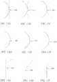
- FIGS. 13A-13Millustrate 2-D representations of these various exemplary configurations of the frame of the two struts of the present invention forming a node, including frames for struts that are straight, curved, or a combination of both. As shown, only two struts intersect each other at the node 1302. At least in FIGS. 13A-13C , the struts intersect one another tangentially at the node 1302, providing increased mechanical strength and bonding.
- FIG. 13A-13Millustrate 2-D representations of these various exemplary configurations of the frame of the two struts of the present invention forming a node, including frames for struts that are straight, curved, or a combination of both. As shown, only two struts intersect each other at the node 1302. At least in FIGS. 13A-13C , the struts intersect one another tangentially at the node 1302, providing increased mechanical strength and bonding.
- FIG. 13A-13Millustrate 2-D representations of these various exemplary configuration
- FIGS. 15A-15Cillustrate 2-D representations of exemplary configurations of the present invention of various curved frames and corresponding struts intersecting to form a node 1502.
- the dashed linesrepresent the frames 1504 and the solid lines represent the corresponding struts 1506.
- node 1502ais formed where the circular strut with its center at 1508 tangentially intersect or meet the circular strut with its center at 1510.
- the node 1502bis formed where the circular strut with its center at 1508 tangentially intersect or meet the circular strut with its center at 1512.
- FIG. 15Bshows the circular strut with its center at 1514 tangentially intersecting the circular strut with its center at 1516 to form node 1502c.
- FIG. 15Cshows the circular strut with its center at 1518 tangentially intersecting the circular strut with its center at 1520 to form node 1502d.
- FIG. 16illustrates a 3-D representation of an exemplary embodiment of the porous structure of the present invention comprising one or more frame configurations in FIGS. 13A-13M , including frames for struts that are straight, curved, or a combination of both.
- FIG. 17illustrates a 3-D representation of an exemplary frame for a generally cubical cell 1700 formed by twelve struts 1702 and sixteen nodes 1704. Again, for simplification purposes, only some of the struts and nodes are labeled.
- sixteen nodes 1704 that form connections between only two struts 1702as opposed to eight nodes that form connections between three struts as in a conventional cube design (not shown)
- the cell 1700provides stronger nodes 1704, and stronger connections between the struts 1702 and nodes 1704.
- this novel configuration of one embodiment of the present inventionavoids variations in cross-sectional diameters between struts 1702 and nodes 1704.
- FIG. 18illustrates a porous structure 1800 formed from a plurality of connected cells 1802, which are similar to those shown in FIG. 17 .
- FIGS. 19-20show another comparison between the arrangement of cells of the prior art in FIG. 19 and one embodiment of the arrangement of cells of the present invention in FIG. 20 .
- the porous structure of the prior artis weak due to the increased effect of the stress risers.
- the arrangement in FIG. 19is weak due to the increased effect of the stress risers.
- FIG. 20 of the present inventionprovides the requisite porosity with an improved strength because no more than two struts intersect at a node.
- the arrangement of FIG. 20has the added benefit of having more trabecular features, resembling the characteristics of cancellous bone, unlike the regular prior art configuration.
- the advantage of looking trabecular while being formed in a calculated mannerprovides another benefit to the porous structures formed in accordance with the invention: a decreased need for expansive randomization of the porous structure. Consequently, the arrangement of FIG. 20 resembles the characteristics of bones more so than the prior art configuration of FIG. 19 .
- FIG. 21is a blown up view of the arrangement in FIG. 20 where the dashed lines 2102 represent the frames of the struts to better show where the struts meet to form a node.
- FIG. 22illustrates another embodiment of a cell of the present invention.
- Cell 2200is based on a tetrahedron-shaped cell, or a triangular pyramid, where it is formed using only six struts 2202 and eight nodes 2204. Each node 2204 connects only two struts 2202 together.
- FIG. 23illustrates a similar cell 2300, which is a square-based pyramid. Referring to FIG. 23 , eight struts 2302 and eleven nodes 2304 are used to form the cell 2300. Other geometrical shapes for cells, such as dodecahedrons, icosahedrons, octagonal prisms, pentagonal prisms, cuboids and various random patterns are discussed below.
- the thickness of each strutcan be selected.
- the thickness for each strutcan be uniform or vary from one strut to another strut.
- the strutscan incorporate the fluted struts of FIGS. 6-8 .
- the strutsdo not have to be cylindrical in shape.
- the cross-section of the strutscan be rectantgular or square or any other shape, e.g ., geometric shape or irregular shapes, that would be suitable for the application.
- various cell designs of various shapescan be created using various techniques discussed above, e.g., DMF.
- DMFdigital multi-dimensional multi-sided design
- cells with an overall geometric shapesuch as Archimedean shapes, Platonic shapes, strictly convex polyhedrons, prisms, anti-prisms and various combinations thereof are within the contemplation of the present invention.
- the number of sides of each cellmay range from about 4 to about 24. More preferably, the number of sides of each cell may range from about 4 to about 16.
- One geometry that has been found to be particularly effectiveis a dodecahedron or 12 sided cell.
- the geometries of the individual cells or the cells of the porous structuremay vary widely and in the geometries may vary randomly from cell to cell of a porous structure.
- FIGS. 24A and 24Billustrate a conventionally designed dodecahedral cell 2400 from a prior art porous structure with each node 2404 being a connection between three struts 2402.
- U.S. Publication Nos. 2006/0147332 and 2010/0010638disclose examples of porous structures formed from these conventional cells.
- a porous structure with a given porosity and having a desired volumecan be formed using a plurality of cells 2400 by attaching one cell 2400 to another cell 2400 until the desired volume is achieved.
- the gagtures using the prior art cell configurationmay be disadvantageous because they do not resemble the randomness of native cancellous structures. That is, they do not adequately resemble the features of trabecular bone.
- FIGS. 25A and 25Billustrate one embodiment of the present invention that provides a solution to these problems of the prior art.
- cell 2500eliminated the conventional nodes 2404 in FIGS. 24A and 24B by using curved struts 2502 that form a ring or hoop, thereby eliminating the stress concentration factors caused by these nodes.
- cells 2500replace conventional nodes 2404 in FIGS. 24A and 24B with modified nodes 2504 that can be open or porous to provide additional porosity, which is an added benefit for many applications, such as enhancing tissue/bone ingrowth for orthopeadic implants. Accordingly, cell 2500 provides additional strength with increased porosity while the conventional cell 2400 is weaker and less porous.
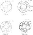
- FIGS. 26-28illustrate one embodiment to forming the cell in FIGS. 25A and 25B .
- FIG. 26illustrates a dodecahedral frame 2600 for prior art cells as discussed with respect to FIGS. 24A and 24B .
- FIG. 27illustrates frame 2700 which comprises frame 2800 of FIG. 28 superimposed over the dodecahedral frame 2600 of FIG. 26.
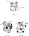
- FIG. 29Aillustrates a cell similar to that of FIGS. 25A and 25B formed by selecting a thickness for frame 2800.
- the cell 2900is constructed from twelve curved struts 2902 that, in this embodiment, may form a ring, a loop, an annulus, or a hoop.
- the curved struts 2902are joined together at triangular modified nodes 2904 that are more easily seen in FIGS. 29B .
- the thicker circlesrepresent four of the curved struts 2902 of the cell 2900 while the thinner circles highlight the modified nodes 2904 formed by struts 2902.
- Each modified node 2904includes three fused connections or sintering junctions 2906 between two different curved struts 2902. That is, curved struts 2902 tangentially intersect one another at the resepective junction 2906.
- modified node 2904may also be porous with openings 2908 disposed between the three junctions 2906 or occluded with no openings disposed between the three junctions 2906.
- modified node 2904has openings 2908 disposed between the three junctions 2906 to provide additional porosity in conjunction with the porosity provided by the fenestrations 2910 of the curved struts 2902.
- the struts' thicknessmay render the individual junctions 2906 relatively long as indicated by the distance 2912. These long, generally tangential sintering junctions 2906 provide increased mechanical strength and bonding.
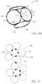
- FIG. 30it depicts an unfolded or flattened two-dimensional representation of FIG. 27 , with conventional frame 3008 and the frame 3010 of cell 2900.
- the location and number of individual junctions 3006, as compared to conventional nodes 3004 of the conventional configuration 3008,is different when using curved struts 3002 provided by the invention.
- junctions 3006are generally located around the center of the body of curved struts 3002, while conventional nodes 3002 is located at the end of the conventional struts.
- the number of junctions 3006 where the curved struts 3002 meetis three times the number of conventional nodes 3004 where straight struts meet for frame 3008. Accordingly, the increased number of junctions provide increased mechanical strength.
- FIGS. 31-34illustrate how frames for cells based on a typical polyhedron can be modified with curved struts to form a cell similar to cell 2900 of FIG. 29 .
- FIG. 31illustrates a frame 3100 of a truncated tetrahedral cell unfolded into a 2-D representation.
- frame 3202represents frame 3100 of FIG. 31 as modified by one embodiment the present invention to be formed with curved struts 3202.
- FIG. 33illustrates the frame 3300 of a truncated octahedral cell unfolded into a 2-D representation
- frame 3402 of FIG. 34represents frame 3300 of FIG.
- the present inventionto be formed with curved struts 3402.
- the cells formed with frames 3200 and 3400have increased mechanical strength and porosity over frames 3100 and 3300, respectively.
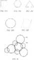
- FIGS. 35A-35Eillustrate one way of modifying a typical polyhedron frame with curved struts.
- the polyhedroncan be modified by inscribing, within the polyhedron, a circle or other shapes that contain curved features, such as an ellipse or oblong.
- FIG. 35Ais a circle inscribed within a square
- FIG. 35Bis a circle inscribed within a hexagon
- FIG. 35Cis a circle inscribed within a triangle
- FIG. 35Dis a circle inscribed within an octagon
- FIG. 35Eis an oval inscribed within a parallelogram.
- FIGS. 35A-35Eare merely demonstrative of the different configurations available and are not intended to limit the scope of the invention.
- FIG. 36illustrates another way of modifying a typical polyhedron frame with curved struts.
- the polyhedroncan be modified by circumscribing the polyhedron with a circle or other shapes that contain curved features, such as an ellipse or oblong.
- FIG. 36illustrates a frame 3600 of a truncated tetrahedral cell with circles 3602 circumscribed around each face of the cell. Some or all portions of frame 3600 may be removed to form a new cell frame that can be used to fabricate a porous structure according to the present invention.
- FIGS. 37-39illustrate embodiments of the present invention that incorporate both straight and curved struts.
- FIGS. 37A and 37Billustrate cell 3700 formed from frame 2700 of FIG. 27 , which is a combination of the dodecahedral frame 2600 of FIG. 26 with frame 2800 of FIG. 28 .
- Cell 3700has increased strength due to the addition of the curved struts, which result in a blending of the stress risers.
- cell 3700has modified node 3704 comprising a conventional node formed with straight struts 3702b and a node formed by three junctions of the curved struts 3702a.
- FIG. 38illustrates cell 3800 formed by keeping one or more conventional nodes 3804 formed by straight struts 3802 while modifying the other struts of the cells with curved struts 3806 to form junctions 3808 and modified nodes 3810.
- some strutsare selectively thicker than other struts, depending on applications.
- the cell 3800has at least one curved strut 3802, and preferably a plurality of curved struts 3802 that form modified node 3804a when joined with two other curved struts 3802.
- the modified nodescan be formed by joining together curved struts, curved strut sections, straight struts, or straight strut sections, or combinations thereof.
- An example of a node formed by joining together straight and curved strutsis shown in FIGS. 39A-39C as modified node 3904b.
- Modified nodes 3804aare preferably triangular formed by three junctions 3806.
- Cell 3800may contain some convention nodes 3808 that join straight struts 3810 or straight strut sections that may comprise notches formed by intersecting angles practiced in the prior art.
- the modified node 3804amay be porous as discussed previously and indicated by 3804a or occluded as indicated at 3804b.
- the occluded modified nodes 3804b and the porous modified nodes 3804amay be formed by tangent sintering three or more junctions 3806 between curved or "ring-like" struts together.
- cell 3900is an example of such combination.
- Cell 3900has curved struts 3902a that are "ring-like" and struts 3902b. It also has straight struts 3906 and conventional nodes 3908. The combination of struts forms porous modified nodes 3904a and occluded modified nodes 3904b.
- the cells 3800 within a porous structuremay be homogeneous, they may be arranged in a random and/or predetermined fashion with respect to each other to more closely resemble the appearance of cancellous bone.
- CADcomputer aided design
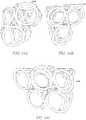
- FIGS. 40 and 41show exemplary configurations of how the cells 2400, 2900, and 3700 from FIGS. 24 , 29 , and 37 , respectively, can be combined, e.g ., attached, joined, tiled, stacked, or repeated.
- FIG. 40illustrates arrangement 4000 comprising cell 2400 and cell 2900 from FIGS. 24 and 29 , respectively.
- conventional nodes 2404is placed partially within modified nodes 2904.
- FIGS. 41A and 41Billustrate arrangement 4100 comprising cells 2400, 2900, and 3700.
- FIGS. 40 and 41are illustrative and do not limit the combination that can be made with these cells or other cells formed according to the embodiments of the present invention.
- FIG. 42illustrates a porous structure 4200 formed by joining a plurality of cells 4202 together, where the shape of cells 4202 is based on a truncated tetrahedron.
- One or more curved struts 4204which may or may not form complete rings are inscribed within, or circumscribed around, each face of the selected polyhedral shape, which is a truncated tetrahedron in FIG. 42 .
- the truncated tetrahedron shape or other selected polyhedral shapemay be formed using a large number of short straight struts to closely approximate truly curved ring struts, such as the ring struts of cell 2900 in FIG. 29 .
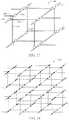
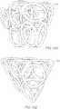
- FIGS. 43-45illustrate 3-D representations of exemplary arrangements cells formed in accordance with the embodiments of the present invention. Specifically, FIG. 43 illustrates one way cells based on truncated octahedra can be stacked to form bitruncated cubic honeycomb structure 4300, which is by space-filling tessellation. The cells of structure 4300 in both shades of gray are truncated octahedra.
- each cellis not modified with a curved strut but rather the dashed circle serves to illustrate that one or more faces of one or more truncated octahedra can be modified according to the embodiments of the present invention, e.g ., curved struts to form porous structures with increased strength and porosity.
- FIG. 44illustrates one way, e.g ., space-filling tessellation, cells based on a combination of cubes (light grey), truncated cuboctahedra (black), and truncated octahedra (dark grey) can be stacked to form cantitruncated cubic honeycomb structure 4400.
- FIG. 45illustrates one way, e.g ., space-filling tessellation, cells based on a combination of cuboctahedra (black), truncated octahedra (dark grey) and truncated tetrahedra (light grey) can be stacked to form truncated alternated cubic honeycomb structure 4500.
- the dashed circlesrepresent how one or more polyhedron of structure 4500 can be modified according to the embodiments of the present invention, e.g ., curved struts to form porous structures with increased strength and porosity.
- FIG. 46illustrates a frame view of the bitruncated cubic honeycomb structure 4300 of FIG. 43 .
- FIG. 47illustrates a frame view cantitruncated cubic honeycomb structure 4500 of FIG. 45 .
- porous structures formed with polyhedralare not random, and thus, are not as suitable for implantation purposes, particularly for bones, because they do not adequately resemble the features of trabecular bone.
- modifying certain or all cells of the frames in FIGS. 46 and 47would result in porous structures resembling trabecular bone.
- At least one curved strut portionmay generally form a portion of a ring which at least partially inscribes or circumscribes a side of a polyhedron.
- a polyhedral shapemay be any one of isogonal or vertex-transitive, isotoxal or edge-transitive, isohedral or face-transitive, regular, quasi-regular, semi-regular, uniform, or noble.
- Disclosed curved strut portionsmay also be at least partially inscribed within or circumscribed around one or more sides of one or more of the following Archimedean shapes: truncated tetrahedrons, cuboctahedrons, truncated cubes ( i.e ., truncated hexahedrons), truncated octahedrons, rhombicuboctahedrons ( i.e ., small rhombicuboctahedrons), truncated cuboctahedrons ( i.e ., great rhombicuboctahedrons), snub cubes ( i.e ., snub hexahedrons, snub cuboctahedrons -- either or both chiral forms), icosidodecahedrons, truncated dodecahedrons, truncated icosahedrons
- Archimedean shapesare highly symmetric, semi-regular convex polyhedrons composed of two or more types of regular polygons meeting in identical vertices, they may generally be categorized as being easily stackable and arrangeable for use in repeating patterns to fill up a volumetric space.
- curved strut portionsare provided to form a porous structure, the curved strut portions generally forming a ring strut portion at least partially inscribing within or circumscribing around one or more polygonal sides of one or more Platonic shapes (e.g ., tetrahedrons, cubes, octahedrons, dodecahedrons, and icosahedrons), uniform polyhedrons (e.g ., prisms, prismatoids such as antiprisms, uniform prisms, right prisms, parallelpipeds, and cuboids), polytopes, polygons, polyhedrons, polyforms, and/or honeycombs.
- Platonic shapese.g ., tetrahedrons, cubes, octahedrons, dodecahedrons, and icosahedrons
- uniform polyhedronse.g ., prisms, prismatoids such as antip
- antiprismsinclude, but are not limited to square antiprisms, octagonal antiprisms, pentagonal antiprisms, decagonal antiprisms, hexagonal antiprsims, and dodecagonal antiprisms.
- a porous structuremay be formed from cells comprising the shape of a strictly convex polyhedron, (e.g ., a Johnson shape), wherein curved strut portions generally form a ring strut portion at least partially inscribed within or circumscribed around one or more face of the strictly convex polyhedron, wherein each face of the strictly convex polyhedron is a regular polygon, and wherein the strictly convex polyhedron is not uniform ( i.e ., it is not a Platonic shape, Archimedean shape, prism, or antiprism).
- a strictly convex polyhedrone.g a Johnson shape
- curved strut portionsgenerally form a ring strut portion at least partially inscribed within or circumscribed around one or more face of the strictly convex polyhedron, wherein each face of the strictly convex polyhedron is a regular polygon, and wherein the strictly convex polyhedron is not uniform ( i.e ., it is not a
- each face of the strictly convex polyhedronmust be the same polygon, or that the same polygons join around each vertex.
- pyramids, cupolas, and rotundasuch as square pyramids, pentagonal pyramids, triangular cupolas, square cupolas, pentagonal cupolas, and pentagonal rotunda are contemplated.
- modified pyramids and dipyramidssuch as elongated triangular pyramids (or elongated tetrahedrons), elongated square pyramids (or augmented cubes), elongated pentagonal pyramids, gyroelongated square pyramids, gyroelongated pentagonal pyramids (or diminished icosahedrons), triangular dipyramids, pentagonal dipyramids, elongated triangular dipyramids, elongated square dipyramids (or biaugmented cubes), elongated pentagonal dipyramids, gyroelongated square dipyramids may be employed.
- Modified cupolas and rotunda shapessuch as elongated triangular cupolas, elongated square cupolas (diminished rhombicuboctahedrons), elongated pentagonal cupolas, elongated pentagonal rotunda, gyroelongated triangular cupolas, gyroelongated square cupolas, gyroelongated pentagonal cupolas, gyroelongated pentagonal rotunda, gyrobifastigium, triangular orthobicupolas (gyrate cuboctahedrons), square orthobicupolas, square gyrobicupolas, pentagonal orthobicupolas, pentagonal gyrobicupolas, pentagonal orthocupolarotunda, pentagonal gyrocupolarotunda, pentagonal orthobirotunda (gyrate icosid
- Augmented prismssuch as augmented triangular prisms, biaugmented triangular prisms, triaugmented triangular prisms, augmented pentagonal prisms, biaugmented pentagonal prisms, augmented hexagonal prisms, parabiaugmented hexagonal prisms, metabiaugmented hexagonal prisms, and triaugmented hexagonal prisms may also be practiced with the invention.
- Modified Platonic shapessuch as augmented dodecahedrons, parabiaugmented dodecahedrons, metabiaugmented dodecahedrons, triaugmented dodecahedrons, metabidiminished icosahedrons, tridiminished icosahedrons, and augmented tridiminished icosahedrons may be employed.
- modified Archimedian shapessuch as augmented truncated tetrahedrons, augmented truncated cubes, biaugmented truncated cubes, augmented truncated dodecahedrons, parabiaugmented truncated dodecahedrons, metabiaugmented truncated dodecahedrons, triaugmented truncated dodecahedrons, gyrate rhombicosidodecahedrons, parabigyrate rhombicosidodecahedrons, metabigyrate rhombicosidodecahedrons, trigyrate rhombicosidodecahedrons, diminished rhombicosidodecahedrons, paragyrate diminished rhombicosidodecahedrons, metagyrate diminished rhombicosidodecahedrons, bigyrate diminished rhombicosidodecahedrons,
- Snub disphenoids(Siamese dodecahedrons), snub square antiprisms, sphenocorona, augmented sphenocorona, sphenomegacorona, hebesphenomegacorona, disphenocingulum, bilunabirotunda, and triangular hebesphenorotunda and other miscellaneous non-uniform convex polyhedron shapes are contemplated.
- the average cross section of the cell fenestrations of the present inventionis in the range of 0.01 to 2000 microns. More preferably, the average cross section of the cell fenestrations is in the range of 50 to 1000 microns. Most preferably, the average cross section of the cell fenestrationsis in the range of 100 to 500 microns.
- Cell fenestrationscan include, but are not limited to, (1) any openings created by the struts such as the open modified pores, e.g ., 3804a of FIG. 38 or 1104 of FIGS. 11A-11F , created by the junctions, e.g ., 3806 of FIG. 38 or nodes 1102 of FIGS.
- the average cross section of a fenestrationmay be the average diameter of that particular fenestration, and in embodimenst where the cell fenestrations are generally rectangular or square, the average cross section of a fenestration may be the average distance going from one side to the opposite side.
- FIGS. 51A and 51Billustrate a cell 5100 formed from an octahedron frame shown in FIG. 48 modified according to one embodiment of the present invention, shown in FIGS. 49-50 .
- frame 4900is formed by inscribing circles within the faces of frame 4800 in FIG. 48 .
- frame 5000is formed by removing frame 4800 from frame 4900 of FIG. 49 .
- the frame 5000generally fits within the octahedron frame 4800.
- FIGS. 51A and 51Billustrate the completed cell 5100, which is formed by selecting a shape and thickness for frame 5000 in FIG. 50 . Referring to FIGS.
- cell 5100generally comprises eight curved struts 5102 that may be provided in the form of rings.
- the eight curved struts 5102are connected to one another at twelve different junctions 5106.
- Six porous modified nodes 5104, each modified node having a generally rectangular shapeare formed by the four different junctions 5106 and the corresponding struts 5102.
- curved struts 5102have a rectangular or square cross-section rather than a circular cross-section of cells similar to cells 2500 in FIGS. 25A and 25B .
- Cells with a rectangular or square cross-sectionprovide the porous structure with a roughness different than that of the cells with a circular cross-section. It is envisioned that struts of other embodiments can have different shapes for a cross-section. Accordingly, the struts of a cell can have the same cross-section, the shape of the cross-section of the struts can be randomly chosen, or the cross-section shape can be selectively picked to achieve the strength, porosity, and/or roughness desired.
- FIGS. 53A-53Dillustrate yet another cell 5300 based on a truncated tetrahedron frame shown in FIG. 52 as modified by one embodiment of the present invention.
- the cell 5300is formed in a similar manner to cell 5100 of FIGS. 51A and 51B . That is, frame 5200 is inscribed with circles to form a second frame comprising circular struts, and frame 5200 is removed leaving behind the circular frame.
- Cell 5300is completed by selecting a thickness and shape of the cross-sectional area for the frame 5300.
- the thickness and shape of the cross-section of the strutscan be uniform or it can vary randomly or in a predetermined manner, including struts with a uniform cross-section or struts that are fluted.
- Cell 5300includes four larger curved struts 5302a that correspond with the four large hexagonal sides of the truncated tetrahedral frame 5200 and four smaller curved struts 5202b that correspond with the four smaller triangular sides of the truncated tetrahedral frame 5200.
- a cellcan be formed by circumscribing a circle about the large sides 5202 and small sides 5204 of the truncated tetrahedral frame 5200.
- FIG. 36A 2-D representation of this alternative embodiment is shown in FIG. 36 . While not expressly shown in the drawings, it is also contemplated that in some embodiments, combinations of inscribed and circumscribed curved struts may be employed. As illustrated in FIGS. 53A-53D , porous triangular modified nodes 5304 are formed between three junctions 5306 that connect the struts 5202a and 5202b together, but those skilled in the art will recognize that occluded modified nodes 3804b as shown in FIG. 38 may also be employed. Also, as shown in FIGS. 53A-53D , larger curved struts 5302a have a circular cross-section while smaller curved struts 5302b have a rectangular cross-section. FIGS.
- 54A-54Eillustrate various angles of a porous structure formed by stacking cells 5300 of FIG. 53 in one exemplary manner. It is envisioned that that in some embodiments, cells 5300 of FIG. 53 can be stacked in different manners as known be a person skilled in the art.
- FIGS. 55A-55Eillustrate yet another embodiment where a cell 5500 is based on a hexagonal prism (Prismatic) frame with upper and lower hexagons and that includes six vertical sides.
- the six smaller curved struts 5502aare used for the six sides and larger upper and lower curved struts 5502b are used for the top and bottom.
- the eight curved struts 5302a, 5302bare connected by occluded modified nodes 5504 but, it will be apparent to those skilled in the art that porous modified nodes such as those shown in FIG. 25 may also be employed.
- porous modified nodessuch as those shown in FIG. 25 may also be employed.
- FIGS. 56A-56Billustrate various angles of a porous structure formed by stacking cells 5500 of FIGS. 55A-55E in one exemplary manner.
- cells 5500are placed adjacent to one another to form a layer 5602 and the layers are placed on top of one another either in a predetermined or random manner.
- FIGS. 56A and 56Billustrate various angles of a porous structure formed by stacking cells 5500 of FIGS. 55A-55E in one exemplary manner.
- cells 5500are placed adjacent to one another to form a layer 5602 and the layers are placed on top of one another either in a predetermined or random manner.
- 57A and 57Bsimilarly show a greater number of cells 5500 stacked in the same manner as shown in FIGS. 56A and 56B .
- cells 5500are stacked by layers 5702. It is envisioned that in some embodiments, cells 5500 of FIG. 55 can be stacked in different manners as known to a person skilled in the art.
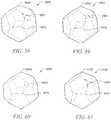
- FIGS. 58-61illustrate dodecahedral frames 5800, 5900, 6000, and 6100 modified according to another embodiment of the invention.
- the particular embodiments of FIGS. 58-61adjust the conventional nodes by ensuring at least one of the conventional nodes have no more than two nodes intersecting at a node as shown by at least FIGS. 11A- 11F .
- frames 5800, 5900, 6000, and 6100have at least one modified node 5804, 5904, 6004, and 6104.
- the configurations of the cells, struts, nodes and/or junctionsmay vary randomly throughout the porous structure to more closely simulate natural bone tissue.
- the cells formed according to the present inventionsuch as the cells illustrated in FIGS. 25A-25B , 29A , 37A-37B, 38 , 39A- 39C , 42 , 51A-51B , 53A-53D , or 55A-55B , can be stacked or repeated according to the methods outlined in U.S. Application No. 61/260,811 .
- the methods of U.S. Application No. 61/260,811can also be employed to modify conventional nodes such that no more than two struts intersect at a node.
- the porous structure formed according to the inventioncan be used in medical implants, such as an orthopedic implant, dental implant or vascular implant.
- the present disclosurealso provides for a method to fabricate the porous structures described above.
- the improved porous structures of the present inventionis formed by using a free-from fabrication method, including rapid manufacturing techniques (RMT) such as direct metal fabrication (DMF).
- RMTrapid manufacturing techniques
- DMFdirect metal fabrication
- the desired structurescan be formed directly from computer controlled databases, which greatly reduces the time and expense required to fabricate various articles and structures.
- RMT or free-form fabricationemploys a computer-aided machine or apparatus that has an energy source such as a laser beam to melt or sinter powder to build the structure one layer at a time according to the model selected in the database of the computer component of the machine.
- RMTis an additive fabrication technique for manufacturing objects by sequential delivering energy and/or material to specified points in space to produce that part.
- the objectscan be produced in a layer-wise fashion from laser-fusible powders that are dispensed one layer at a time.
- the powderis fused, melted, remelted, or sintered, by application of the laser energy that is directed in raster-scan fashion to portions of the powder layer corresponding to a cross section of the object. After fusing the powder on one particular layer, an additional layer of powder is dispensed, and the process is repeated until the object is completed.
- the porous structureis formed from powder that is selected from the group consisting of metal, ceramic, metal-ceramic (cermet), glass, glass-ceramic, polymer, composite and combinations thereof.
- metallic powderis used and is selected from the group consisting of titanium, titanium alloy, zirconium, zirconium alloy, niobium, niobium alloy, tantalum, tantalum alloy, nickel-chromium (e.g., stainless steel), cobalt-chromium alloy and combinations thereof.
- the modelis built by starting with a prior art configuration and modifying the struts and nodes of the prior art configuration by either (1) adjusting the number struts that intersect at a node, such as the configurations in FIGS. 3-8 , 11A-11F , 12A-12D , 17-20 , or 22-23 , or (2) introduce curved portions to the struts such as the configurations in FIGS. 13A-13M , 14 , 15A-15C , 16 , or 58-61 .
- curved "ring-like" strutscan be added to form cells illustrated in FIGS. 25A-25B , 29A , 37A-37B, 38 , 39A-39C , 42 , 51A-51B , 53A-53D , or 55A- 55B .
- these cellscan be formed by starting with a frame 2600 based on a polyhedron, such as a dodecahedron.
- the next stepis to inscribe circles within each face of the frame 2600 to form frame 2700, which is frame 2800 superimposed on frame 2600. Subsequently, frame 2600 can be removed from frame 2700, leaving only frame 2800.
- the thickness and shape of the cross-section of frame 2800can be selected to form a completed cell, such as cell 2900 in FIG. 29A .
- a portion of the faces of frame 2600can be inscribed with circles and/or a portion of frame 2600 can be removed to form, or frame 2600 is not removed at all.
- the cells formed by such combinationsare illustrated in FIGS. 37A-37B, 38 , and 39A-39C .
- FIGS. 48-53 and 55the same steps can be applied to any type of frames based on a polyhedron.
- stacking, tiling or repeating algorithmcan be applied to create a model of a porous structure with the desired dimensions formed from unit cells or struts and nodes of the present invention.
- One such stacking algorithmis space filling tessellation shown by FIGS. 43-45 .
- the methods disclosed in U.S. Application No. 61/260,81 leanbe applied to stack the cells of the present invention or to form the struts according to the disclosures of the present invention by controlled randomization.
Landscapes
- Health & Medical Sciences (AREA)
- Chemical & Material Sciences (AREA)
- Engineering & Computer Science (AREA)
- Materials Engineering (AREA)
- Manufacturing & Machinery (AREA)
- Animal Behavior & Ethology (AREA)
- Transplantation (AREA)
- Life Sciences & Earth Sciences (AREA)
- Oral & Maxillofacial Surgery (AREA)
- General Health & Medical Sciences (AREA)
- Public Health (AREA)
- Veterinary Medicine (AREA)
- Epidemiology (AREA)
- Medicinal Chemistry (AREA)
- Dermatology (AREA)
- Composite Materials (AREA)
- Orthopedic Medicine & Surgery (AREA)
- Cardiology (AREA)
- Biomedical Technology (AREA)
- Heart & Thoracic Surgery (AREA)
- Vascular Medicine (AREA)
- Dispersion Chemistry (AREA)
- Structural Engineering (AREA)
- Ceramic Engineering (AREA)
- Civil Engineering (AREA)
- Inorganic Chemistry (AREA)
- Prostheses (AREA)
- Powder Metallurgy (AREA)
- Materials For Medical Uses (AREA)
- Dental Preparations (AREA)
Description
- The present invention generally relates to porous structures suitable for medical implants, and more particularly to porous structures suitable for medical implants that have improved combinations of strength, porosity and connectivity and methods for fabricating such improved porous structures.
- Metal foam structures are porous, three-dimensional structures with a variety of uses, including medical implants. Metal foam structures are suitable for medical implants, particularly orthopedic implants, because they have the requisite strength for weight bearing purposes as well as the porosity to encourage bone/tissue in-growth. For example, many orthopedic implants include porous sections that provide a scaffold structure to encourage bone in-growth during healing and a weight bearing section intended to render the patient ambulatory more quickly.
- Metal foam structures can be fabricated by a variety of methods. For example, one such method is mixing a powdered metal with a pore-forming agent (PFA) and then pressing the mixture into the desired shape. The PFA is removed using heat in a "burn out" process. The remaining metal skeleton may then be sintered to form a porous metal foam structure.
- Another similar conventional method include applying a binder to polyurethane foam, applying metal powder to the binder, burning out the polyurethane foam and sintering the metal powder together to form a "green" part. Binder and metal powder are re-applied to the green part and the green part is re- sintered until the green part has the desired strut thickness and porosity. The green part is then machined to the final shape and re- sintered.
- While metal foams formed by such conventional methods provide good porosity, they may not provide sufficient strength to serve as weight bearing structures in many medical implants. Further, the processes used to form metal foams may lead to the formation of undesirable metal compounds in the metal foams by the reaction between the metal and the PFA. Conventional metal foam fabrication processes also consume substantial amounts of energy and may produce noxious fumes.
- Rapid manufacturing technologies (RMT) such as direct metal fabrication (DMF) and solid free-form fabrication (SFF) have recently been used to produce metal foam used in medical implants or portions of medical implants. In general, RMT methods allow for structures to be built from 3-D CAD models. For example, DMF techniques produce three-dimensional structures one layer at a time from a powder which is solidified by irradiating a layer of the powder with an energy source such as a laser or an electron beam. The powder is fused, melted or sintered, by the application of the energy source, which is directed in raster-scan fashion to selected portions of the powder layer. After fusing a pattern in one power layer, an additional layer of powder is dispensed, and the process is repeated with fusion taking place between the layers, until the desired structure is complete.
- Examples of metal powders reportedly used in such direct fabrication techniques include two-phase metal powders of the copper-tin, copper-solder and bronze-nickel systems. The metal structures formed by DMF may be relatively dense, for example, having densities of 70% to 80% of a corresponding molded metal structure, or conversely, may be relatively porous, with porosities approaching 80% or more.
- While DMF can be used to provide dense structures strong enough to serve as weight bearing structures in medical implants, such structures do not have enough porosity to promote tissue and bone in-growth. Conversely, DMF can be used to provide porous structures having enough porosity to promote tissue and bone in-growth, but such porous structures lack the strength needed to serve as weight bearing structures. Other laser RMT techniques are similarly deficient for orthopedic implants requiring strength, porosity and connectivity.
- As a result of the deficiencies of metal foam implants and implants fabricated using conventional DMF methods, some medical implants require multiple structures, each designed for one or more different purposes. For example, because some medical implants require both a porous structure to promote bone and tissue in-growth and a weight bearing structure, a porous plug may be placed in a recess of a solid structure and the two structures may then be joined by sintering. Obviously, using a single structure would be preferable to using two distinct structures and sintering them together.
EP1683593 describes porous structures having nodes at which more than two struts intersect and methods of making such structures. - The patent
EP1683593A2 discloses a method of producing a three-dimensional porous tissue in-growth structure, the method comprises depositing a first layer of a powder made from a metal onto a substrate; and scanning a laser beam to form a portion of a plurality of predetermined unit cells. - In light of the above, there is still a need for porous implant structures that provide both the required strength and desired porosity, particularly for various orthopedic applications. This disclosure provides improved porous structures that have both the strength suitable for weight bearing structures and the porosity suitable for tissue in-growth structures and a method for fabricating such improved porous structures.
- One objective of the invention is to provide porous biocompatible structures suitable for use as medical implants that have improved strength and porosity as disclosed in claim 1.
- Another objective of the invention is to provide methods to fabricate porous biocompatible structures suitable for use as medical implants that have improved strength and porosity as disclosed in claim 12.
- To meet the above objectives, there is provided, in accordance with one aspect of the invention, there is a porous structure comprising: a plurality of struts, each strut comprises a first end, a second end; and a continuous elongated body between the first and second ends, where the body has a thickness and a length; and a plurality of nodes, each node comprises an intersection between one end of a first strut and the body of a second strut, wherein no more than two struts intersect at a node
- In a preferred embodiment, the first and second ends of one or more struts extend between the body of two other struts. In another preferred embodiment, the body of one or more struts comprise a plurality of nodes.
- In accordance with another aspect of the invention, there is a porous structure comprising a plurality of struts, wherein one or more struts comprise a curved portion having a length and thickness; a plurality of junctions where two of said curved portions intersect tangentially; and a plurality of modified nodes, each modified node comprises an opening formed by three or more of said junctions.
- In a preferred embodiment, the porous structure includes at least one strut comprising a straight portion having a length and a thickness. In another preferred embodiment, the porous structure includes at least one strut having a first end, a second end; and a continuous elongated body between the first and second ends, where the body has a thickness and a length; and at least one closed node comprising an intersection between one end of a first strut and the body of a second strut, wherein the strut can comprise of a straight portion, a curved portion, or both.
- In accordance with another aspect of the invention, there are methods for fabricating a porous structure. One such method is as claimed in claim 12. Another such method comprises the steps of: creating a model of the porous structure, the creation step comprises defining a plurality of struts and a plurality of nodes to form the porous structure and fabricating the porous structure according to the model by exposing metallic powder to an energy source. The defining step comprises the steps of providing a first end, a second end; and a continuous elongated body between the first and second ends for each strut, selecting a thickness and a length for the body; and providing an intersection between one end of a first strut and the body of a second strut for each node.
- In a preferred embodiment, the method includes defining the first and second ends of one or more struts extend between the body of two other struts. In another preferred embodiment, defining the body of one or more struts to comprise a plurality of nodes.
- Also described herein is a method for fabricating a porous structure comprising the steps of: creating a model of the porous structure; the creation step comprises selecting at least one frame shape and size for one or more cells of the porous structure, where the frame shape comprises a geometric shape selected from the group consisting of Archimedean shapes, Platonic shapes, strictly convex polyhedrons, prisms, anti-prisms and combinations thereof; adding one or more struts to the frame where the struts comprises a curved portion, said adding step is performed by inscribing or circumscribing the curved portion of the one or more struts within or around one or more faces of the selected shape; selecting a thickness for the frame and the one or more struts; and fabricating the porous structure according to the model by exposing metallic powder to an energy source.
- In a preferred embodiment, the creation step includes the step of removing a portion of the frame from one or more cells of the model. In another preferred embodiment, the fabrication step includes defining N(1, x) layer-by-layer patterns for the porous structure based on the selected dimensions, at least one cell shape and at least one cell size, where N ranges from 1 for the first layer at a bottom of the porous structure to x for the top layer at a top of the porous structure; depositing an Nth layer of powdered biocompatible material; fusing or sintering the Nth pattern in the deposited Nth layer of powdered biocompatible material; and repeating the depositing and fusing or sintering steps for N=1 through N=x.
- In a refinement, the method may further comprise creating a model of the porous structure wherein, for at least some nodes, no more than two struts intersect at the same location.
- In another refinement, the method may comprise creating a model of the porous structure wherein at least one strut or strut portion is curved.
- The disclosed porous structures may be fabricated using a rapid manufacturing technologies such as direct metal fabrication process. The struts can be sintered, melted, welded, bonded, fused, or otherwise connected to another strut. The struts and nodes can define a plurality of fenestrations. Further, the struts and nodes can be fused, melted, welded, bonded, sintered, or otherwise connected to one another to form a cell, which can be fused, melted, welded, bonded, sintered, or otherwise connected to other cells to form a continuous reticulated structure.
- In some refinements, at least one, some, or all struts of a cell may have a uniform strut diameter. In some refinements, one, some, or all of the struts of a cell may have a non-uniform strut diameter. In some refinements, a cell may have combinations of struts having uniform and non-uniform strut diameters. In some refinements, at least one, some, or all of the uniform diameter struts of a cell may or may not share similar, different, or identical strut diameters, longitudinal shapes, cross-sectional shapes, sizes, shape profiles, strut thicknesses, material characteristics, strength profiles, or other properties. In some refinements, one, some, or all struts within a cell may grow or shrink in diameter at similar, different, or identical rates along a predetermined strut length.
- In some refinements, struts within a cell may extend between two nodes. In a further refinement of this concept, struts may have varying cross-sectional diameters along a strut length, including a minimum diameter at a middle portion disposed between the two nodes. In further refinement of this concept, struts may have two opposing ends, with each end connected to a node and a middle portion disposed between the two ends. Struts may flare or taper outwardly as they extend from the middle portion towards each node so that a diameter of the middle portion is generally smaller than a diameter of either or both of the two opposing ends. In some instances, the struts may flare in a parabolic fluted shape or may taper frusto-conically.
- In other refinements, at least one, some, or all struts within a cell are curved. In further refinement of this concept, one, some, or all of the cells within a porous structure comprise at least one curved strut. In further refinement of this concept, all of the struts that make up a porous structure are curved. In further refinement of this concept, curved struts may form complete rings or ring segments. The rings or ring segments may be inter-connected to form open sides or fenestrations of multiple-sided cells. In some instances, a single ring may form a shared wall portion which connects two adjacent multiple-sided cells. In some instances, one or more ring segments alone or in combination with straight strut portions may form a shared wall portion which connects two adjacent multiple-sided cells. In still a further refinement, the number of sides of each cell may range from about 4 to about 24. More preferably, the number of sides of each cell may range from about 4 to about 16. One geometry that has been found to be particularly effective is a dodecahedron or 12 sided cell. However, as explained and illustrated below, the geometries of the individual cells or the cells of the porous structure may vary widely and in the geometries may vary randomly from cell to cell of a porous structure.
- In another refinement, the configurations of the cells, struts, nodes and/or junctions may vary randomly throughout the porous structure to more closely simulate natural bone tissue.
- In another refinement, each cell may be multiple-sided and having an overall shape that may fit within a geometric shape selected from the group consisting of tetrahedrons, truncated tetrahedrons, cuboctahedrons, truncated hexahedrons, truncated octahedrons, rhombicuboctahedrons, truncated cuboctahedrons, snub hexahedrons, snub cuboctahedrons, icosidodecahedrons, truncated dodecahedrons, truncated icosahedrons, rhombicosidodecahedrons, truncated icosidodecahedrons, snub dodecahedrons, snub icosidodecahedrons, cubes, octahedrons, dodecahedrons, icosahedrons, prisms, prismatoids, antiprisms, uniform prisms, right prisms, parallelpipeds, cuboids, polytopes, honeycombs, square pyramids, pentagonal pyramids, triangular cupolas, square cupolas, pentagonal cupolas, pentagonal rotundas, elongated triangular pyramids, elongated square pyramids, elongated pentagonal pyramids, gyroelongated square pyramids, gyroelongated pentagonal pyramids, triangular dipyramids, pentagonal dipyramids, elongated triangular dipyramids, elongated square dipyramids, elongated pentagonal dipyramids, gyroelongated square dipyramids, elongated triangular cupolas, elongated square cupolas, elongated pentagonal cupolas, elongated pentagonal rotundas, gyroelongated triangular cupolas, gyroelongated square cupolas, gyroelongated pentagonal cupolas, gyroelongated pentagonal rotundas, gyrobifastigium, triangular orthobicupolas, square orthobicupolas, square gyrobicupolas, pentagonal orthobicupolas, pentagonal gyrobicupolas, pentagonal orthocupolarotundas, pentagonal gyrocupolarotundas, pentagonal orthobirotundas, elongated triangular orthobicupolas, elongated triangular gyrobicupolas, elongated square gyrobicupolas, elongated pentagonal orthobicupolas, elongated pentagonal gyrobicupolas, elongated pentagonal orthocupolarotundas, elongated pentagonal gyrocupolarotundas, elongated pentagonal orthobirotundas, elongated pentagonal gyrobirotundas, gyroelongated triangular bicupolas, gyroelongated square bicupolas, gyroelongated pentagonal bicupolas, gyroelongated pentagonal cupolarotundas, gyroelongated pentagonal birotundas, augmented triangular prisms, biaugmented triangular prisms, triaugmented triangular prisms, augmented pentagonal prisms, biaugmented pentagonal prisms, augmented hexagonal prisms, parabiaugmented hexagonal prisms, metabiaugmented hexagonal prisms, triaugmented hexagonal prisms, augmented dodecahedrons, parabiaugmented dodecahedrons, metabiaugmented dodecahedrons, triaugmented dodecahedrons, metabidiminished icosahedrons, tridiminished icosahedrons, augmented tridiminished icosahedrons, augmented truncated tetrahedrons, augmented truncated cubes, biaugmented truncated cubes, augmented truncated dodecahedrons, parabiaugmented truncated dodecahedrons, metabiaugmented truncated dodecahedrons, triaugmented truncated dodecahedrons, gyrate rhombicosidodecahedrons, parabigyrate rhombicosidodecahedrons, metabigyrate rhombicosidodecahedrons, trigyrate rhombicosidodecahedrons, diminished rhombicosidodecahedrons, paragyrate diminished rhombicosidodecahedrons, metagyrate diminished rhombicosidodecahedrons, bigyrate diminished rhombicosidodecahedrons, parabidiminished rhombicosidodecahedrons, metabidiminished rhombicosidodecahedrons, gyrate bidiminished rhombicosidodecahedrons, and tridiminished rhombicosidodecahedrons, snub disphenoids, snub square antiprisms, sphenocorons, augmented sphenocoronas, sphenomegacorona, hebesphenomegacorona, disphenocingulum, bilunabirotundas, triangular hebesphenorotundas, and combinations thereof.
- In another refinement, the powder is selected from the group consisting of metal, ceramic, metal-ceramic (cermet), glass, glass-ceramic, polymer, composite and combinations thereof.
- In another refinement, the metallic material is selected from the group consisting of titanium, titanium alloy, zirconium, zirconium alloy, niobium, niobium alloy, tantalum, tantalum alloy, nickel-chromium (e.g., stainless steel), cobalt-chromium alloy and combinations thereof.
- In another refinement, the porous structure forms at least a portion of a medical implant, such as an orthopedic implant, dental implant or vascular implant.
- Porous orthopedic implant structures for cell and tissue in-growth and weight bearing strength are also disclosed that may be fabricated using a near-net shape manufacturing process such as a direct metal fabrication (DMF) process for use with metallic biomaterials or a stereo-lithography manufacturing process for use with polymeric biomaterials. In instances where a DMF process is utilized, a powdered biocompatible material is provided in layers and individual particles of one layer of powdered biocompatible material are fused or sintered together one layer at a time. Exemplary porous structures comprise a plurality of three-dimensional cells. Each cell comprises a plurality of struts. Each strut may be sintered or fused to one other strut at a node. Each node may comprise a junction of not more than two struts. The struts and nodes of each cell define a plurality of fenestrations. Each cell comprises from about 4 to about 24 fenestrations. At least one strut of at least some of the cells are curved. Each cell may be fused or sintered to at least one other cell to form a continuous reticulated structure.
- Other advantages and features will be apparent from the following detailed description when read in conjunction with the attached drawings. The foregoing has outlined rather broadly the features and technical advantages of the present invention in order that the detailed description of the invention that follows may be better understood. Additional features and advantages of the invention will be described hereinafter which form the subject of the claims of the invention. It should be appreciated by those skilled in the art that the conception and specific embodiment disclosed may be readily utilized as a basis for modifying or designing other structures for carrying out the same purposes of the present invention. The novel features which are believed to be characteristic of the invention, both as to its organization and method of operation, together with further objects and advantages will be better understood from the following description when considered in connection with the accompanying figures. It is to be expressly understood, however, that each of the figures is provided for the purpose of illustration and description only and is not intended as a definition of the limits of the present invention.
- For a more complete understanding of the present invention, reference is now made to the following descriptions taken in conjunction with the accompanying drawing, in which:
FIGS. 1A-1B illustrate 3-D representations of an example of the struts at a node in a porous structure of the prior art where the struts ofFIG. 1A have like diameters and the struts ofFIG. 1B have different diameters.FIG. 2 is a SEM (Scanning Electron Microscope) microphotograph of an example of fractured struts of the prior art.FIGS. 3-5 illustrate 3-D representations of one embodiment of the struts and nodes of the present invention.FIGS. 6-8 illustrate 3-D representations of another embodiment of the struts and nodes of the present invention where at least some of the struts comprises a smaller cross-sectional diameter at the body portion of the strut as compared to the cross-sectional diameter at the node.FIGS. 9A and 9B illustrate plan views of the embodiments inFIGS. 6-8 .FIGS. 10A-10F illustrate 2-D representations of various configurations of the frame of struts and nodes in a porous structure of the prior art.FIGS. 11A-11F illustrate 2-D representations of the corresponding configurations of the frame of struts and nodes of the prior art inFIGS. 10A-10F modified by one embodiment of the present invention.FIGS. 12A-12D illustrate 3-D representations of exemplary embodiments of the porous structure of the present invention comprising one or more frame configurations inFIGS. 11A-11F .FIGS. 13A-13M illustrate 2-D representations of various exemplary configurations of the frame of the two struts of the present invention forming a node, including frames for struts that are straight, curved, or a combination of both.FIG. 14 illustrates a 2-D representation of an exemplary embodiment of the porous structure of the present invention comprising one or more frame configurations inFIGS. 13A-13M .FIGS. 15A-15C illustrate 2-D representations of exemplary configurations of various curved frames and corresponding struts of the present invention intersecting to form a node.FIG. 16 illustrates a 3-D representation of an exemplary embodiment of the porous structure of the present invention comprising one or more frame configurations inFIGS. 13A-13M , including frames for struts that are straight, curved, or a combination of both.FIG. 17 illustrates a 3-D representation of an exemplary frame for a generally cubical cell of the porous structure of the present invention.FIG. 18 illustrates a 3-D representation of an exemplary arrangement of frames for cubical cells inFIG. 17 .FIG. 19 illustrates a 3-D representation of an arrangement of cubical cells of the porous structure of the prior art.FIG. 20 illustrates a 3-D representation of an exemplary arrangement of cubical cells of the porous structure of the present invention.FIG. 21 illustrates a blown up view of the arrangement inFIG. 20 .FIG. 22 illustrates a 3-D representation of an exemplary frame for a tetrahedron-shaped cell of the porous structure of the present invention.FIG. 23 illustrates a 3-D representation of an exemplary frame for square-based pyramid cell of the porous structure of the present invention.FIGS. 24A and 24B illustrate various views of 3-D representations of a conventional cell of the porous structure of the prior art based on a dodecahedral shape.FIGS. 25A and 25B illustrate various views of 3-D representations of one embodiment of a cell of the porous structure of the present invention also based on a dodecahedral shape.FIGS. 26-28 illustrate 3-D representations of a frame of the convention cell inFIGS. 24A and 24B modified by one embodiment of the present invention.FIGS. 29A and29B illustrate 3-D representations of a cell of the present invention formed fromFIGS. 26-28 , whereFIG. 29B is a partial view of a 3-D representation of the frame of the cell.FIG. 30 illustrates the frame ofFIG. 27 unfolded into a 2-D representation.FIG. 31 illustrates a frame of a truncated tetrahedral cell unfolded into a 2-D representation.FIG. 32 illustrates the frame ofFIG. 31 formed with curved struts according to one embodiment of the present invention.FIG. 33 illustrates the frame of a truncated octahedral cell unfolded into a 2-D representation.FIG. 34 illustrates the frame ofFIG. 33 formed with curved struts according to one embodiment of the present invention.FIGS. 35A-35E illustrate 2-D representations of examples of a circle or an ellipse inscribed within various geometric shapes according to one embodiment of the present invention.FIG. 36 illustrates the frame of a truncated tetrahedral cell unfolded into a 2-D representation with circles circumscribed around each face of the cell according to one embodiment of the present invention.FIGS. 37A and 37B illustrate various views of 3-D representations of another embodiment of a cell of the present invention based on a dodecahedral shape.FIG. 38 illustrates a 3-D representation of yet another embodiment of a cell of the present invention based on a dodecahedral shape.FIGS. 39A-38C illustrate various views of 3-D representations of yet another embodiment of a cell of the present invention based on a dodecahedral shape.FIG. 40 illustrates a 3-D representation of an exemplary arrangement of the cells ofFIGS. 24 and 25 .FIGS. 41A and41B illustrate various views of 3-D representations of an exemplary arrangement of the cells ofFIGS. 24, 25 , and37 FIG. 42 illustrates a 3-D representation of an exemplary arrangement of the cells based on a truncated tetrahedral shape having one or more curved struts.FIG. 43 illustrates a 3-D representation of an exemplary arrangement of the present invention of cells based on truncated octahedra.FIG. 44 illustrates a 3-D representation of an exemplary arrangement of the present invention of cells based on cubes (light grey), truncated cuboctahedra (black), and truncated octahedra (dark grey).FIG. 45 illustrates a 3-D representation of an exemplary arrangement of the present invention of cells based on cuboctahedra (black), truncated octahedra (dark grey) and truncated tetrahedra (light grey).FIG. 46 illustrates a frame view of the arrangement ofFIG. 42 .FIG. 47 illustrates a frame view of the arrangement ofFIG. 43 .FIGS. 48-50 illustrate 3-D reprsentations of a frame based an octahedron modified by one embodiment of the present invention.FIGS. 51A and 51B illustrate various views of 3-D representations of a cell of the present invention formed from the frames ofFIGS. 48-50 .FIG. 52 illustrates a 3-D representation of a frame based a truncated tetrahedron.FIGS. 53A-53D illustrate various views of 3-D representations of a cell formed from the frame ofFIG. 52 that was modified by one embodiment of the present invention.FIGS. 54A-54E illustrate various views of 3-D representations of an exemplary arrangement of the cells ofFIG. 53 .FIGS. 55A-55E illustrate 3-D representations of a cell formed from a frame based on a hexagonal prism that was modified by one embodiment of the present invention.FIGS. 56A-56B and 57A-57B illustrate 3-D representations of an exemplary arrangement of the cells ofFIG. 55 .FIGS. 58-61 illustrate 3-D representations of frames based on a dodecahedron modified by various embodiments of the present invention.- It should be understood that the drawings are not necessarily to scale and that the disclosed embodiments are sometimes illustrated diagrammatically and in partial views. In certain instances, details which are not necessary for an understanding of the disclosed methods and apparatuses or which render other details difficult to perceive may have been omitted. Also, for simplification purposes, there may be only one exemplary instance, rather than all, is labeled. It should be understood, of course, that this disclosure is not limited to the particular embodiments illustrated herein.
- As discussed above, Rapid Manufacturing Techniques (RMT) such as Direct Metal Fabrication (DMF) can be used to produce porous structures for medical implants. However, using DMF or other RMT to fabricate porous structures can create weak areas between fenestrations of the three-dimensional porous structure. This is mostly due to the shapes and configurations of the cells that have been used in the prior art to form these porous structures. In particular, fractures typically occur at areas where struts are connected together at a node. The fractures occur in porous structures of the prior art because the cross-sectional area of a strut where it connects to the node is typically less than the cross-sectional area of the resulting node. The areas where the struts connect to their node, typically referred to as stress risers, are common points of structural failure. The pattern of failure at the stress risers can also occur when the molten phase of particles does not completely melt and fuse together or when the surrounding substrate surfaces is too cold, which causes the hot powdered material to bead up during the DMF process. Regardless of the exact causes of strut fractures and the resulting poor performance of porous structures of the prior art, improved porous structures that can be fabricated using RMT, including DMF, and other free-form fabrication and near net-shape processes (e.g., selective laser sintering, electron beam melting, and stereo-lithography) are desired.
FIGS. 1A and 1B provide an illustration of where fractures may occur.FIGS. 1A-1B illustrate an example of a porous structure with three or four struts, respectively, connected at a single node, where the struts ofFIG. 1A have the same diameters and the struts ofFIG. 1B have different diameters. Specifically, inFIG. 1A , threestruts 102 of generally equal diameters are connected together atnode 104. Threestress risers 106 are created at the connections between the three struts 102. Because the cross-sectional diameters ofstruts 102 at thestress risers 106 are less than the cross-sectional diameter of thenode 104, thestress risers 106 are locations for a typical strut failure. InFIG. 1B , threesmaller struts 108 are connected to alarger strut 110 at anode 112. Three of the four resulting stress risers are shown at 114, which have substantially smaller cross-sectional diameters than thenode 112.FIG. 2 is a SEM (Scanning Electron Microscope) microphotograph of astructure 200 fabricated using RMT, and it shows an example of strut fracture surfaces 202. InFIG. 2 , the sample shown is occluded withbuild powder 204 in the areas around the strut fracture surfaces 202.- Referring to
FIGS. 3-5 , various embodiments of the present invention are shown. InFIGS. 3-5 , struts 302, 402, and 502 are connected together at theirrespective nodes nodes FIG. 5 ,node 504a comprises a connection betweenstruts node 504b comprises a connection betweenstruts node 504c comprises a connection betweenstruts struts respective nodes struts respective nodes FIGS. 3-5 . Consequently, the resulting structures are substantially stronger than the structures of the prior art illustrated inFIGS. 1A-1B . FIGS. 6-8 illustrate alternative embodiments of the porous structures of the present invention comprising strut and node combinations where at least some of the struts are characterized by a smaller cross-sectional diameter at the body of the strut than at the stress riser. Thestruts struts respective nodes FIGS. 6-8 illustrate incorporatefluted struts non-fluted struts respective nodes - Thus, each of the connections between the
fluted struts non-fluted struts fluted struts FIG. 9A , it is a plan view of thestruts 802 andnodes 804 inFIG. 8 .FIG. 9B is a plan view of an individual node inFIGS. 6-8 , which is labeled asstruts 602 andnode 604 for demonstrative purposes. Referring toFIGS. 9A-9B , the fluted struts 602, 802 have a larger or maximum cross-sectional diameter at theends nodes struts non-fluted struts FIGS. 10A-10F illustrate 2-D representations of various configurations of the frame of the struts and nodes in a porous structure of the prior art. For simplification purposes, the struts are not represented in 3-D but rather each strut is represented by a different line,e.g., its frame, that is either solid, bolded solid, or dashed lines. This representation is simply exemplary and not meant to be limiting. In the prior art, it is typical for a porous structure to have more than two struts meeting at anode 1002, regardless whether the strut may be straight, curved or irregular. WhileFIG. 10A may show two struts meeting at a node, the stress risers of this configuration has the effect of the stress risers at a node with four struts connecting or intersecting one another. For example,U.S. Publication Nos. 2006/0147332 and2010/0010638 show examples of these prior art configurations employed to form porous structures.- In contrast, to the prior art configurations of
FIGS. 10A-10F , the present invention reduces the effect of the stress risers at the nodes by ensuring that no more than two struts intersect at a node. Consequently, some embodiments result in the diameter or cross-sectional area where the struts intersect being substantially equal to the cross-sectional area at each node, thereby reducing the effect of the stress risers on the strength of the structure.FIGS. 11A-11F illustrate exemplary embodiments of the present invention for modifying the corresponding configurations of the prior art to ensure that no more than two struts intersect at a node. As seen inFIGS. 11A-11F , each ofnodes 1102 has only two struts intersecting. For simplification purposes, only one of the numerous nodes in 11A-11F is labeled with thenumber 1102. In particular, theFIGS. 11A-11F show atnodes 1102, the end of one strut intersect the body of another strut. Further, the modification of the prior art configurations according to one embodiment of the present invention forms a modifiedpore 1104 that is open in each configuration that provides additional porosity with added strength, which is a great improvement over the prior art.FIGS. 12A-12D illustrate 3-D representations of exemplary embodiments of the porous structure of the present invention formed with one or more configurations inFIGS. 11A-11F , where the frames,e.g., lines, have been given a thickness to form struts. InFIGS. 12A-12D , the porous structures havestruts 1202 that intersect one another atnodes 1204 where no more than two nodes intersect at a node. - As demonstrated by
FIGS. 11A-11F , theconventional nodes 1002 ofFIGS. 10A-10F are effectively being "opened" up to ensure that no more than two struts meet at a node. In addition to reducing the effect of stress risers at the node, this "opening" up of theconventional nodes 1002 ofFIGS. 10A-10F intonodes 1102 ofFIGS. 11A-11F has the added benefit of reducing heat variations during the fabrication process. As with any other thermal processes, being able to control the heat variations,e.g., cooling, of the material is important to obtain the desired material properties. - Referring to
FIGS. 13A-13M , the present invention also provides for embodiments that reduce the effect of stress risers by incorporating curved struts into the porous structures.FIGS. 13A-13M illustrate 2-D representations of these various exemplary configurations of the frame of the two struts of the present invention forming a node, including frames for struts that are straight, curved, or a combination of both. As shown, only two struts intersect each other at thenode 1302. At least inFIGS. 13A-13C , the struts intersect one another tangentially at thenode 1302, providing increased mechanical strength and bonding.FIG. 14 illustrates 2-D representation of an exemplary embodiment of the porous structure of the present invention comprising one or more frame configurations inFIGS. 13A-13M , including frames for struts that are straight, curved, or a combination of both. As shown byFIG. 14 , no more than two struts, whether curved or straight, meet at each node.FIGS. 15A-15C illustrate 2-D representations of exemplary configurations of the present invention of various curved frames and corresponding struts intersecting to form a node 1502. InFIGS. 15A-15C , the dashed lines represent theframes 1504 and the solid lines represent the correspondingstruts 1506. As shown,node 1502a is formed where the circular strut with its center at 1508 tangentially intersect or meet the circular strut with its center at 1510. Thenode 1502b is formed where the circular strut with its center at 1508 tangentially intersect or meet the circular strut with its center at 1512. Similarly,FIG. 15B shows the circular strut with its center at 1514 tangentially intersecting the circular strut with its center at 1516 to formnode 1502c. Likewise,FIG. 15C shows the circular strut with its center at 1518 tangentially intersecting the circular strut with its center at 1520 to form node 1502d.FIG. 16 illustrates a 3-D representation of an exemplary embodiment of the porous structure of the present invention comprising one or more frame configurations inFIGS. 13A-13M , including frames for struts that are straight, curved, or a combination of both. FIG. 17 illustrates a 3-D representation of an exemplary frame for a generallycubical cell 1700 formed by twelvestruts 1702 and sixteennodes 1704. Again, for simplification purposes, only some of the struts and nodes are labeled. By using sixteennodes 1704 that form connections between only twostruts 1702 as opposed to eight nodes that form connections between three struts as in a conventional cube design (not shown), thecell 1700 providesstronger nodes 1704, and stronger connections between thestruts 1702 andnodes 1704. As a result, this novel configuration of one embodiment of the present invention avoids variations in cross-sectional diameters betweenstruts 1702 andnodes 1704. As a result, the negative effects of stress risers like those shown atstress risers FIGS. 1A-1B on the strength of the structure are lessened.FIG. 18 illustrates aporous structure 1800 formed from a plurality of connected cells 1802, which are similar to those shown inFIG. 17 . Similarly,FIGS. 19-20 show another comparison between the arrangement of cells of the prior art inFIG. 19 and one embodiment of the arrangement of cells of the present invention inFIG. 20 . As previously discussed, by having more than two struts intersect at a node, the porous structure of the prior art is weak due to the increased effect of the stress risers. On the other hand, the arrangement inFIG. 20 of the present invention provides the requisite porosity with an improved strength because no more than two struts intersect at a node. In addition, the arrangement ofFIG. 20 has the added benefit of having more trabecular features, resembling the characteristics of cancellous bone, unlike the regular prior art configuration. Moreover, the advantage of looking trabecular while being formed in a calculated manner provides another benefit to the porous structures formed in accordance with the invention: a decreased need for expansive randomization of the porous structure. Consequently, the arrangement ofFIG. 20 resembles the characteristics of bones more so than the prior art configuration ofFIG. 19 .FIG. 21 is a blown up view of the arrangement inFIG. 20 where the dashedlines 2102 represent the frames of the struts to better show where the struts meet to form a node.- Similarly,
FIG. 22 illustrates another embodiment of a cell of the present invention.Cell 2200 is based on a tetrahedron-shaped cell, or a triangular pyramid, where it is formed using only sixstruts 2202 and eightnodes 2204. Eachnode 2204 connects only twostruts 2202 together.FIG. 23 illustrates asimilar cell 2300, which is a square-based pyramid. Referring toFIG. 23 , eightstruts 2302 and elevennodes 2304 are used to form thecell 2300. Other geometrical shapes for cells, such as dodecahedrons, icosahedrons, octagonal prisms, pentagonal prisms, cuboids and various random patterns are discussed below. In addition,FIGS. 17, 18 ,22 and 23 illustrate frames of struts that can be built from these frames where the thickness of each strut can be selected. As such, the thickness for each strut can be uniform or vary from one strut to another strut. Further, the struts can incorporate the fluted struts ofFIGS. 6-8 . In addition, the struts do not have to be cylindrical in shape. As further discussed below, the cross-section of the struts can be rectantgular or square or any other shape,e.g., geometric shape or irregular shapes, that would be suitable for the application. - As discussed above with respect to
FIGS. 17, 18 ,22, and 23 , various cell designs of various shapes can be created using various techniques discussed above,e.g., DMF. Generally speaking, almost any three-dimensional multiple-sided design may be employed. For example, cells with an overall geometric shape such as Archimedean shapes, Platonic shapes, strictly convex polyhedrons, prisms, anti-prisms and various combinations thereof are within the contemplation of the present invention. In other embodiments, the number of sides of each cell may range from about 4 to about 24. More preferably, the number of sides of each cell may range from about 4 to about 16. One geometry that has been found to be particularly effective is a dodecahedron or 12 sided cell. However, as explained and illustrated below, the geometries of the individual cells or the cells of the porous structure may vary widely and in the geometries may vary randomly from cell to cell of a porous structure. - For example,
FIGS. 24A and 24B illustrate a conventionally designeddodecahedral cell 2400 from a prior art porous structure with eachnode 2404 being a connection between threestruts 2402. Again,U.S. Publication Nos. 2006/0147332 and2010/0010638 disclose examples of porous structures formed from these conventional cells. A porous structure with a given porosity and having a desired volume can be formed using a plurality ofcells 2400 by attaching onecell 2400 to anothercell 2400 until the desired volume is achieved. Further, the tructures using the prior art cell configuration may be disadvantageous because they do not resemble the randomness of native cancellous structures. That is, they do not adequately resemble the features of trabecular bone. More importantly, referring toFIGS. 24A and 24B , higher stresses are placed at eachnode 2404 because thestruts 2402 intersect one another at 120° angles, thereby increasing stress concentration factors due to the formation of notches or grooves on the face of thenodes 2404 and the connection between more than twostruts 2402 at eachnode 2404. FIGS. 25A and 25B illustrate one embodiment of the present invention that provides a solution to these problems of the prior art. As shown byFIGS. 25A and 25B ,cell 2500 eliminated theconventional nodes 2404 inFIGS. 24A and 24B by usingcurved struts 2502 that form a ring or hoop, thereby eliminating the stress concentration factors caused by these nodes. In addition,cells 2500 replaceconventional nodes 2404 inFIGS. 24A and 24B with modifiednodes 2504 that can be open or porous to provide additional porosity, which is an added benefit for many applications, such as enhancing tissue/bone ingrowth for orthopeadic implants. Accordingly,cell 2500 provides additional strength with increased porosity while theconventional cell 2400 is weaker and less porous.FIGS. 26-28 illustrate one embodiment to forming the cell inFIGS. 25A and 25B .FIG. 26 illustrates adodecahedral frame 2600 for prior art cells as discussed with respect toFIGS. 24A and 24B .FIG. 27 illustratesframe 2700 which comprisesframe 2800 ofFIG. 28 superimposed over thedodecahedral frame 2600 ofFIG. 26. FIG. 29A illustrates a cell similar to that ofFIGS. 25A and 25B formed by selecting a thickness forframe 2800. InFIG. 29A , thecell 2900 is constructed from twelvecurved struts 2902 that, in this embodiment, may form a ring, a loop, an annulus, or a hoop. Thecurved struts 2902 are joined together at triangular modifiednodes 2904 that are more easily seen inFIGS. 29B . Referring toFIG. 29B , the thicker circles represent four of thecurved struts 2902 of thecell 2900 while the thinner circles highlight the modifiednodes 2904 formed bystruts 2902. Each modifiednode 2904 includes three fused connections orsintering junctions 2906 between two differentcurved struts 2902. That is,curved struts 2902 tangentially intersect one another at theresepective junction 2906. Depending on the thickness of eachstrut 2902, modifiednode 2904 may also be porous withopenings 2908 disposed between the threejunctions 2906 or occluded with no openings disposed between the threejunctions 2906. Preferably, modifiednode 2904 hasopenings 2908 disposed between the threejunctions 2906 to provide additional porosity in conjunction with the porosity provided by thefenestrations 2910 of thecurved struts 2902. Referring toFIG. 29B , while thestruts 2906 tangentially intersect one another,e.g., their frame tangentially meet, the struts' thickness may render theindividual junctions 2906 relatively long as indicated by thedistance 2912. These long, generallytangential sintering junctions 2906 provide increased mechanical strength and bonding.- Referring to
FIG. 30 , it depicts an unfolded or flattened two-dimensional representation ofFIG. 27 , withconventional frame 3008 and theframe 3010 ofcell 2900. As shown byFIG. 30 , the location and number ofindividual junctions 3006, as compared toconventional nodes 3004 of theconventional configuration 3008, is different when usingcurved struts 3002 provided by the invention. For example,junctions 3006 are generally located around the center of the body ofcurved struts 3002, whileconventional nodes 3002 is located at the end of the conventional struts. In addition, in this particular embodiment, the number ofjunctions 3006 where thecurved struts 3002 meet is three times the number ofconventional nodes 3004 where straight struts meet forframe 3008. Accordingly, the increased number of junctions provide increased mechanical strength. FIGS. 31-34 illustrate how frames for cells based on a typical polyhedron can be modified with curved struts to form a cell similar tocell 2900 ofFIG. 29 . Specifically,FIG. 31 illustrates aframe 3100 of a truncated tetrahedral cell unfolded into a 2-D representation. InFIG. 32 ,frame 3202 representsframe 3100 ofFIG. 31 as modified by one embodiment the present invention to be formed withcurved struts 3202. Similarly,FIG. 33 illustrates theframe 3300 of a truncated octahedral cell unfolded into a 2-D representation, andframe 3402 ofFIG. 34 representsframe 3300 ofFIG. 31 as modified by one embodiment the present invention to be formed withcurved struts 3402. As discussed above,e.g., with respect toFIG. 30 , the cells formed withframes frames FIGS. 35A-35E illustrate one way of modifying a typical polyhedron frame with curved struts. According to one embodiment of the invention, the polyhedron can be modified by inscribing, within the polyhedron, a circle or other shapes that contain curved features, such as an ellipse or oblong. Specifically,FIG. 35A is a circle inscribed within a square,FIG. 35B is a circle inscribed within a hexagon,FIG. 35C is a circle inscribed within a triangle,FIG. 35D is a circle inscribed within an octagon, andFIG. 35E is an oval inscribed within a parallelogram.FIGS. 35A-35E are merely demonstrative of the different configurations available and are not intended to limit the scope of the invention.FIG. 36 illustrates another way of modifying a typical polyhedron frame with curved struts. According to another embodiment of the invention, the polyhedron can be modified by circumscribing the polyhedron with a circle or other shapes that contain curved features, such as an ellipse or oblong.FIG. 36 illustrates aframe 3600 of a truncated tetrahedral cell withcircles 3602 circumscribed around each face of the cell. Some or all portions offrame 3600 may be removed to form a new cell frame that can be used to fabricate a porous structure according to the present invention.FIGS. 37-39 illustrate embodiments of the present invention that incorporate both straight and curved struts. Specifically,FIGS. 37A and 37B illustratecell 3700 formed fromframe 2700 ofFIG. 27 , which is a combination of thedodecahedral frame 2600 ofFIG. 26 withframe 2800 ofFIG. 28 .Cell 3700 has increased strength due to the addition of the curved struts, which result in a blending of the stress risers. As shown,cell 3700 has modifiednode 3704 comprising a conventional node formed withstraight struts 3702b and a node formed by three junctions of thecurved struts 3702a.FIG. 38 illustratescell 3800 formed by keeping one or more conventional nodes 3804 formed bystraight struts 3802 while modifying the other struts of the cells withcurved struts 3806 to form junctions 3808 and modifiednodes 3810. InFIG. 38 some struts are selectively thicker than other struts, depending on applications.- Referring to
FIG. 38 , thecell 3800 has at least onecurved strut 3802, and preferably a plurality ofcurved struts 3802 that form modified node 3804a when joined with two othercurved struts 3802. In other embodiments, the modified nodes can be formed by joining together curved struts, curved strut sections, straight struts, or straight strut sections, or combinations thereof. An example of a node formed by joining together straight and curved struts is shown inFIGS. 39A-39C as modifiednode 3904b. Modified nodes 3804a are preferably triangular formed by threejunctions 3806.Cell 3800 may contain some convention nodes 3808 that joinstraight struts 3810 or straight strut sections that may comprise notches formed by intersecting angles practiced in the prior art. The modified node 3804a may be porous as discussed previously and indicated by 3804a or occluded as indicated at 3804b. The occluded modifiednodes 3804b and the porous modified nodes 3804a may be formed by tangent sintering three ormore junctions 3806 between curved or "ring-like" struts together. Any combination ofoccluded nodes 3804b, porous modified nodes 3804a, conventional nodes 3808,straight struts 3810, curvedstruts 3802, and portions or segments thereof may be used in different predetermined or random ways in order to create stronger, more cancellous-appearing cell structure. Referring toFIGS. 39A-39C ,cell 3900 is an example of such combination.Cell 3900 hascurved struts 3902a that are "ring-like" and struts 3902b. It also hasstraight struts 3906 andconventional nodes 3908. The combination of struts forms porous modifiednodes 3904a and occluded modifiednodes 3904b. - Thus, while the
cells 3800 within a porous structure may be homogeneous, they may be arranged in a random and/or predetermined fashion with respect to each other to more closely resemble the appearance of cancellous bone. In some instances, it may be desirable to utilize one or more heterogeneous cell configurations which may be arranged systematically in predetermined patterns and/or arranged in random fashion to create a porous structure. Various arrangements can be designed using computer aided design (CAD) software or other equivalent software as will be apparent to those skilled in the art. FIGS. 40 and41 show exemplary configurations of how thecells FIGS. 24 ,29 , and37 , respectively, can be combined,e.g., attached, joined, tiled, stacked, or repeated. Specifically,FIG. 40 illustratesarrangement 4000 comprisingcell 2400 andcell 2900 fromFIGS. 24 and29 , respectively. Inarrangement 4000, at the face wherecell 2400 attaches tocell 2900,conventional nodes 2404 is placed partially within modifiednodes 2904. Accordingly, by using various combinations ofcells 2400 andcells 2900, or other cells formed according to the present invention, a number of modifiednodes 2504 can be selectively occluded completely or partially by matching conventional nodes with modified nodes.FIGS. 41A and41B illustratearrangement 4100 comprisingcells FIGS. 40 and41 are illustrative and do not limit the combination that can be made with these cells or other cells formed according to the embodiments of the present invention.FIG. 42 illustrates aporous structure 4200 formed by joining a plurality ofcells 4202 together, where the shape ofcells 4202 is based on a truncated tetrahedron. One or morecurved struts 4204 which may or may not form complete rings are inscribed within, or circumscribed around, each face of the selected polyhedral shape, which is a truncated tetrahedron inFIG. 42 . Alternatively, the truncated tetrahedron shape or other selected polyhedral shape may be formed using a large number of short straight struts to closely approximate truly curved ring struts, such as the ring struts ofcell 2900 inFIG. 29 .FIGS. 43-45 illustrate 3-D representations of exemplary arrangements cells formed in accordance with the embodiments of the present invention. Specifically,FIG. 43 illustrates one way cells based on truncated octahedra can be stacked to form bitruncatedcubic honeycomb structure 4300, which is by space-filling tessellation. The cells ofstructure 4300 in both shades of gray are truncated octahedra. For simplification purposes, each cell is not modified with a curved strut but rather the dashed circle serves to illustrate that one or more faces of one or more truncated octahedra can be modified according to the embodiments of the present invention,e.g., curved struts to form porous structures with increased strength and porosity. Similarly,FIG. 44 illustrates one way,e.g., space-filling tessellation, cells based on a combination of cubes (light grey), truncated cuboctahedra (black), and truncated octahedra (dark grey) can be stacked to form cantitruncatedcubic honeycomb structure 4400. Again, it is understood that the dashed circles represent how one or more polyhedron ofporous structure 4400 can be modified according to the embodiments of the present invention,e.g., curved struts to form porous structures with increased strength and porosity. Likewise,FIG. 45 illustrates one way,e.g., space-filling tessellation, cells based on a combination of cuboctahedra (black), truncated octahedra (dark grey) and truncated tetrahedra (light grey) can be stacked to form truncated alternatedcubic honeycomb structure 4500. Again, it is understood that the dashed circles represent how one or more polyhedron ofstructure 4500 can be modified according to the embodiments of the present invention,e.g., curved struts to form porous structures with increased strength and porosity.FIG. 46 illustrates a frame view of the bitruncatedcubic honeycomb structure 4300 ofFIG. 43 .FIG. 47 illustrates a frame view cantitruncatedcubic honeycomb structure 4500 ofFIG. 45 . As shown byFIGS. 46 and 47 , porous structures formed with polyhedral are not random, and thus, are not as suitable for implantation purposes, particularly for bones, because they do not adequately resemble the features of trabecular bone. On the other hand, as it can be envisioned that modifying certain or all cells of the frames inFIGS. 46 and 47 would result in porous structures resembling trabecular bone.- When curved struts are employed, at least one curved strut portion may generally form a portion of a ring which at least partially inscribes or circumscribes a side of a polyhedron. Such a polyhedral shape may be any one of isogonal or vertex-transitive, isotoxal or edge-transitive, isohedral or face-transitive, regular, quasi-regular, semi-regular, uniform, or noble. Disclosed curved strut portions may also be at least partially inscribed within or circumscribed around one or more sides of one or more of the following Archimedean shapes: truncated tetrahedrons, cuboctahedrons, truncated cubes (i.e., truncated hexahedrons), truncated octahedrons, rhombicuboctahedrons (i.e., small rhombicuboctahedrons), truncated cuboctahedrons (i.e., great rhombicuboctahedrons), snub cubes (i.e., snub hexahedrons, snub cuboctahedrons -- either or both chiral forms), icosidodecahedrons, truncated dodecahedrons, truncated icosahedrons (i.e., buckyball or soccer ball-shaped), rhombicosidodecahedrons (i.e., small rhombicosidodecahedrons), truncated icosidodecahedrons (i.e., great rhombicosidodecahedrons), snub dodecahedron or snub icosidodecahedrons (either or both chiral forms). Since Archimedean shapes are highly symmetric, semi-regular convex polyhedrons composed of two or more types of regular polygons meeting in identical vertices, they may generally be categorized as being easily stackable and arrangeable for use in repeating patterns to fill up a volumetric space.
- In some embodiments, curved strut portions according to the invention are provided to form a porous structure, the curved strut portions generally forming a ring strut portion at least partially inscribing within or circumscribing around one or more polygonal sides of one or more Platonic shapes (e.g., tetrahedrons, cubes, octahedrons, dodecahedrons, and icosahedrons), uniform polyhedrons (e.g., prisms, prismatoids such as antiprisms, uniform prisms, right prisms, parallelpipeds, and cuboids), polytopes, polygons, polyhedrons, polyforms, and/or honeycombs. Examples of antiprisms include, but are not limited to square antiprisms, octagonal antiprisms, pentagonal antiprisms, decagonal antiprisms, hexagonal antiprsims, and dodecagonal antiprisms.
- In yet other embodiments, a porous structure may be formed from cells comprising the shape of a strictly convex polyhedron, (e.g., a Johnson shape), wherein curved strut portions generally form a ring strut portion at least partially inscribed within or circumscribed around one or more face of the strictly convex polyhedron, wherein each face of the strictly convex polyhedron is a regular polygon, and wherein the strictly convex polyhedron is not uniform (i.e., it is not a Platonic shape, Archimedean shape, prism, or antiprism). In such embodiments, there is no requirement that each face of the strictly convex polyhedron must be the same polygon, or that the same polygons join around each vertex. In some examples, pyramids, cupolas, and rotunda such as square pyramids, pentagonal pyramids, triangular cupolas, square cupolas, pentagonal cupolas, and pentagonal rotunda are contemplated. Moreover, modified pyramids and dipyramids such as elongated triangular pyramids (or elongated tetrahedrons), elongated square pyramids (or augmented cubes), elongated pentagonal pyramids, gyroelongated square pyramids, gyroelongated pentagonal pyramids (or diminished icosahedrons), triangular dipyramids, pentagonal dipyramids, elongated triangular dipyramids, elongated square dipyramids (or biaugmented cubes), elongated pentagonal dipyramids, gyroelongated square dipyramids may be employed. Modified cupolas and rotunda shapes such as elongated triangular cupolas, elongated square cupolas (diminished rhombicuboctahedrons), elongated pentagonal cupolas, elongated pentagonal rotunda, gyroelongated triangular cupolas, gyroelongated square cupolas, gyroelongated pentagonal cupolas, gyroelongated pentagonal rotunda, gyrobifastigium, triangular orthobicupolas (gyrate cuboctahedrons), square orthobicupolas, square gyrobicupolas, pentagonal orthobicupolas, pentagonal gyrobicupolas, pentagonal orthocupolarotunda, pentagonal gyrocupolarotunda, pentagonal orthobirotunda (gyrate icosidodecahedron), elongated triangular orthobicupolas, elongated triangular gyrobicupolas, elongated square gyrobicupolas (gyrate rhombicuboctahedrons), elongated pentagonal orthobicupolas, elongated pentagonal gyrobicupolas, elongated pentagonal orthocupolarotunda, elongated pentagonal gyrocupolarotunda, elongated pentagonal orthobirotunda, elongated pentagonal gyrobirotunda, gyroelongated triangular bicupolas (either or both chiral forms), gyroelongated square bicupolas (either or both chiral forms), gyroelongated pentagonal bicupolas (either or both chiral forms), gyroelongated pentagonal cupolarotunda (either or both chiral forms), and gyroelongated pentagonal birotunda (either or both chiral forms) may be utilised. Augmented prisms such as augmented triangular prisms, biaugmented triangular prisms, triaugmented triangular prisms, augmented pentagonal prisms, biaugmented pentagonal prisms, augmented hexagonal prisms, parabiaugmented hexagonal prisms, metabiaugmented hexagonal prisms, and triaugmented hexagonal prisms may also be practiced with the invention. Modified Platonic shapes such as augmented dodecahedrons, parabiaugmented dodecahedrons, metabiaugmented dodecahedrons, triaugmented dodecahedrons, metabidiminished icosahedrons, tridiminished icosahedrons, and augmented tridiminished icosahedrons may be employed. Moreover, modified Archimedian shapes such as augmented truncated tetrahedrons, augmented truncated cubes, biaugmented truncated cubes, augmented truncated dodecahedrons, parabiaugmented truncated dodecahedrons, metabiaugmented truncated dodecahedrons, triaugmented truncated dodecahedrons, gyrate rhombicosidodecahedrons, parabigyrate rhombicosidodecahedrons, metabigyrate rhombicosidodecahedrons, trigyrate rhombicosidodecahedrons, diminished rhombicosidodecahedrons, paragyrate diminished rhombicosidodecahedrons, metagyrate diminished rhombicosidodecahedrons, bigyrate diminished rhombicosidodecahedrons, parabidiminished rhombicosidodecahedrons, metabidiminished rhombicosidodecahedrons, gyrate bidiminished rhombicosidodecahedrons, and tridiminished rhombicosidodecahedrons are envisaged. Snub disphenoids (Siamese dodecahedrons), snub square antiprisms, sphenocorona, augmented sphenocorona, sphenomegacorona, hebesphenomegacorona, disphenocingulum, bilunabirotunda, and triangular hebesphenorotunda and other miscellaneous non-uniform convex polyhedron shapes are contemplated.
- In some embodiments, the average cross section of the cell fenestrations of the present invention is in the range of 0.01 to 2000 microns. More preferably, the average cross section of the cell fenestrations is in the range of 50 to 1000 microns. Most preferably, the average cross section of the cell fenestrationsis in the range of 100 to 500 microns. Cell fenestrations can include, but are not limited to, (1) any openings created by the struts such as the open modified pores,e.g., 3804a of
FIG. 38 or 1104 ofFIGS. 11A-11F , created by the junctions,e.g., 3806 ofFIG. 38 ornodes 1102 ofFIGS. 11A-11F , or (2) any openings inscribed by the struts themselves,e.g., 2910 ofFIG. 29B . For example, in embodiments where the cell fenestrations are generally circular, the average cross section of a fenestration may be the average diameter of that particular fenestration, and in embodimenst where the cell fenestrations are generally rectangular or square, the average cross section of a fenestration may be the average distance going from one side to the opposite side. - Applying the above principles to other embodiments,
FIGS. 51A and 51B illustrate acell 5100 formed from an octahedron frame shown inFIG. 48 modified according to one embodiment of the present invention, shown inFIGS. 49-50 . InFIG. 49 ,frame 4900 is formed by inscribing circles within the faces offrame 4800 inFIG. 48 . InFIG. 50 ,frame 5000 is formed by removingframe 4800 fromframe 4900 ofFIG. 49 . As shown inFIG. 49 , theframe 5000 generally fits within theoctahedron frame 4800.FIGS. 51A and 51B illustrate the completedcell 5100, which is formed by selecting a shape and thickness forframe 5000 inFIG. 50 . Referring toFIGS. 51A and 51B ,cell 5100 generally comprises eightcurved struts 5102 that may be provided in the form of rings. The eightcurved struts 5102 are connected to one another at twelvedifferent junctions 5106. Six porous modifiednodes 5104, each modified node having a generally rectangular shape are formed by the fourdifferent junctions 5106 and the correspondingstruts 5102. As shown byFIGS. 51A and 51B , unlike the curved struts ofcell 2500 ofFIGS. 25A and 25B ,curved struts 5102 have a rectangular or square cross-section rather than a circular cross-section of cells similar tocells 2500 inFIGS. 25A and 25B . Cells with a rectangular or square cross-section provide the porous structure with a roughness different than that of the cells with a circular cross-section. It is envisioned that struts of other embodiments can have different shapes for a cross-section. Accordingly, the struts of a cell can have the same cross-section, the shape of the cross-section of the struts can be randomly chosen, or the cross-section shape can be selectively picked to achieve the strength, porosity, and/or roughness desired. - As another alternative,
FIGS. 53A-53D illustrate yet anothercell 5300 based on a truncated tetrahedron frame shown inFIG. 52 as modified by one embodiment of the present invention. Referring toFIGS. 53A-53D , thecell 5300 is formed in a similar manner tocell 5100 ofFIGS. 51A and 51B . That is,frame 5200 is inscribed with circles to form a second frame comprising circular struts, andframe 5200 is removed leaving behind the circular frame.Cell 5300 is completed by selecting a thickness and shape of the cross-sectional area for theframe 5300. As discussed above, the thickness and shape of the cross-section of the struts can be uniform or it can vary randomly or in a predetermined manner, including struts with a uniform cross-section or struts that are fluted.Cell 5300 includes four largercurved struts 5302a that correspond with the four large hexagonal sides of the truncatedtetrahedral frame 5200 and four smaller curved struts 5202b that correspond with the four smaller triangular sides of the truncatedtetrahedral frame 5200. Alternative, a cell can be formed by circumscribing a circle about the large sides 5202 and small sides 5204 of the truncatedtetrahedral frame 5200. A 2-D representation of this alternative embodiment is shown inFIG. 36 . While not expressly shown in the drawings, it is also contemplated that in some embodiments, combinations of inscribed and circumscribed curved struts may be employed. As illustrated inFIGS. 53A-53D , porous triangular modifiednodes 5304 are formed between threejunctions 5306 that connect the struts 5202a and 5202b together, but those skilled in the art will recognize that occluded modifiednodes 3804b as shown inFIG. 38 may also be employed. Also, as shown inFIGS. 53A-53D , largercurved struts 5302a have a circular cross-section while smallercurved struts 5302b have a rectangular cross-section.FIGS. 54A-54E illustrate various angles of a porous structure formed by stackingcells 5300 ofFIG. 53 in one exemplary manner. It is envisioned that that in some embodiments,cells 5300 ofFIG. 53 can be stacked in different manners as known be a person skilled in the art. FIGS. 55A-55E illustrate yet another embodiment where acell 5500 is based on a hexagonal prism (Prismatic) frame with upper and lower hexagons and that includes six vertical sides. The six smallercurved struts 5502a are used for the six sides and larger upper and lowercurved struts 5502b are used for the top and bottom. In thecell 5500 illustrated inFIGS. 55A-55E , the eightcurved struts nodes 5504 but, it will be apparent to those skilled in the art that porous modified nodes such as those shown inFIG. 25 may also be employed. In the particular embodiment shown inFIGS. 55A-55E , the six smallercurved struts 5502a used for the six sides have a slightly smaller cross-sectional area than the two larger upper and lowercurved struts 5302b. However, it would be apparent to those skilled in the art that the struts with uniform or substantially uniform cross-sectional areas can also be employed without departing from the scope of this disclosure.FIGS. 56A-56B illustrate various angles of a porous structure formed by stackingcells 5500 ofFIGS. 55A-55E in one exemplary manner. InFIGS. 56A and 56B ,cells 5500 are placed adjacent to one another to form alayer 5602 and the layers are placed on top of one another either in a predetermined or random manner.FIGS. 57A and 57B similarly show a greater number ofcells 5500 stacked in the same manner as shown inFIGS. 56A and 56B . As seen,cells 5500 are stacked bylayers 5702. It is envisioned that in some embodiments,cells 5500 ofFIG. 55 can be stacked in different manners as known to a person skilled in the art.FIGS. 58-61 illustratedodecahedral frames conventional nodes FIGS. 58-61 adjust the conventional nodes by ensuring at least one of the conventional nodes have no more than two nodes intersecting at a node as shown by at leastFIGS. 11A- 11F . As shown byFIGS. 58-61 , frames 5800, 5900, 6000, and 6100 have at least one modifiednode - In some embodiment, the configurations of the cells, struts, nodes and/or junctions may vary randomly throughout the porous structure to more closely simulate natural bone tissue. Particularly, the cells formed according to the present invention, such as the cells illustrated in
FIGS. 25A-25B ,29A ,37A-37B, 38 ,39A- 39C ,42 ,51A-51B ,53A-53D , or55A-55B , can be stacked or repeated according to the methods outlined inU.S. Application No. 61/260,811 U.S. Application No. 61/260,811 - As further discussed in the following paragraphs, the present disclosure also provides for a method to fabricate the porous structures described above.
Preferably, the improved porous structures of the present invention is formed by using a free-from fabrication method, including rapid manufacturing techniques (RMT) such as direct metal fabrication (DMF). Generally, in free-form fabrication techniques, the desired structures can be formed directly from computer controlled databases, which greatly reduces the time and expense required to fabricate various articles and structures. Typically in RMT or free-form fabrication employs a computer-aided machine or apparatus that has an energy source such as a laser beam to melt or sinter powder to build the structure one layer at a time according to the model selected in the database of the computer component of the machine. - For example, RMT is an additive fabrication technique for manufacturing objects by sequential delivering energy and/or material to specified points in space to produce that part. Particularly, the objects can be produced in a layer-wise fashion from laser-fusible powders that are dispensed one layer at a time. The powder is fused, melted, remelted, or sintered, by application of the laser energy that is directed in raster-scan fashion to portions of the powder layer corresponding to a cross section of the object. After fusing the powder on one particular layer, an additional layer of powder is dispensed, and the process is repeated until the object is completed.
- Detailed descriptions of selective laser sintering technology may be found in
U.S. Patent Nos. 4,863,538 ;5,017,753 ;5,076,869 ; and4,944,817 . Current practice is to control the manufacturing process by computer using a mathematical model created with the aid of a computer. Consequently, RMT such as selective laser re-melting and sintering technologies have enabled the direct manufacture of solid or 3-D structures of high resolution and dimensional accuracy from a variety of materials. - In one embodiment of the present invention, the porous structure is formed from powder that is selected from the group consisting of metal, ceramic, metal-ceramic (cermet), glass, glass-ceramic, polymer, composite and combinations thereof. In another embodiment, metallic powder is used and is selected from the group consisting of titanium, titanium alloy, zirconium, zirconium alloy, niobium, niobium alloy, tantalum, tantalum alloy, nickel-chromium (e.g., stainless steel), cobalt-chromium alloy and combinations thereof.
- As known by those skilled in the art, creating models of cells or structures according to the disclosure of the present invention can be done with computer aided design (CAD) software or other similar software. In one embodiment, the model is built by starting with a prior art configuration and modifying the struts and nodes of the prior art configuration by either (1) adjusting the number struts that intersect at a node, such as the configurations in
FIGS. 3-8 ,11A-11F ,12A-12D ,17-20 , or22-23 , or (2) introduce curved portions to the struts such as the configurations inFIGS. 13A-13M ,14 ,15A-15C ,16 , or58-61 . In another embodiment, curved "ring-like" struts can be added to form cells illustrated inFIGS. 25A-25B ,29A ,37A-37B, 38 ,39A-39C ,42 ,51A-51B ,53A-53D , or55A- 55B . Referring toFIG. 26 , in one embodiment, these cells can be formed by starting with aframe 2600 based on a polyhedron, such as a dodecahedron. Referring toFIG. 27 , the next step is to inscribe circles within each face of theframe 2600 to formframe 2700, which isframe 2800 superimposed onframe 2600.
Subsequently,frame 2600 can be removed fromframe 2700, leaving onlyframe 2800. The thickness and shape of the cross-section offrame 2800 can be selected to form a completed cell, such ascell 2900 inFIG. 29A . As discussed above, a portion of the faces offrame 2600 can be inscribed with circles and/or a portion offrame 2600 can be removed to form, orframe 2600 is not removed at all. The cells formed by such combinations are illustrated inFIGS. 37A-37B, 38 , and39A-39C . As shown byFIGS. 48-53 and55 , the same steps can be applied to any type of frames based on a polyhedron. Also with the aid of computer software, stacking, tiling or repeating algorithm can be applied to create a model of a porous structure with the desired dimensions formed from unit cells or struts and nodes of the present invention. One such stacking algorithm is space filling tessellation shown byFIGS. 43-45 . As mentioned above, the methods disclosed inU.S. Application No. 61/260,81 lean be applied to stack the cells of the present invention or to form the struts according to the disclosures of the present invention by controlled randomization. - It will be understood that the scope of the present application is not intended to be limited to the particular embodiments of the process, machine, manufacture, composition of matter, means, methods and steps described in the specification. As one of ordinary skill in the art will readily appreciate from the disclosure of the present invention, processes, machines, manufacture, compositions of matter, means, methods, or steps, presently existing or later to be developed that perform substantially the same function or achieve substantially the same result as the corresponding embodiments described herein may be utilized according to the present invention. Accordingly, the appended claims are intended to include within their scope such processes, machines, manufacture, compositions of matter, means, methods, or steps.
Claims (22)
- A porous structure comprising:
a plurality of struts, each strut comprises:a first end;a second end; anda continuous elongated body between said first and second ends, said body having a thickness and a length; anda plurality of nodes, each node comprises an intersection between one end of a first strut and the body of a second strut, wherein no more than two struts intersect at a node. - The porous structure of claim 1, wherein the first and second ends of one or more struts extend between the body of two other struts.
- The porous structure of claim 1 or claim 2, wherein the body of one or more struts comprise a plurality of nodes.
- The porous structure of any preceding claim, wherein the cross-section of at least one end of one or more struts is larger than the cross-section of a portion of the body of said one or more struts.
- The porous structure of any preceding claim, wherein at least a portion of the body of one or more struts is curved.
- The porous structure of any preceding claim, wherein the plurality of struts can be sintered, melted, welded, bonded, fused, or otherwise connected to one another.
- The porous structure of any preceding claim, wherein a plurality of the struts and nodes defines at least one fenestration.
- The porous structure of any preceding claim, further comprising material selected from the group consisting of metal, ceramic, metal-ceramic, glass, glass-ceramic, polymer, composite and combinations thereof.
- The porous structure of claim 8, wherein the metallic material is selected from the group consisting of titanium, titanium alloy, zirconium, zirconium alloy, niobium, niobium alloy, tantalum, tantalum alloy, nickel-chromium, cobalt-chromium alloy and combinations thereof.
- The porous structure of any preceding claim, wherein the cross section of one or more struts comprises a polygon.
- The porous structure of any preceding claim, wherein at least a portion of the cross-section is curved.
- A method for fabricating a porous structure comprising the steps of:creating a model of the porous structure, wherein the creation step comprises:defining one or more struts with a first end, a second end, and a continuous elongated body between the first and second ends for each strut, selecting a thickness and length for the body; anddefining at least one node with an intersection between one end of a first strut and the body of a second strut for each node, wherein no more than two struts intersect at a node; andfabricating the porous structure according to the model by exposing fusible material to an energy source.
- The method of claim 12, which further comprises the step of defining the first and second ends of one or more struts to extend between the body of two other struts.
- The method of claim 12 or claim 13, which further comprises the step of defining the body of one or more struts to comprise a plurality of nodes.
- The method of any of claims 12 to 14, which further comprises the step of defining the cross-section of at least one end of one or more struts to be larger than the cross-section of a portion of the body of said one or more struts.
- The method of any of claims 12 to 15, which further comprises the step of defining at least a portion of the body of one or more struts to be curved.
- The method of any of claims 12 to 16, which further comprises the step of sintering, melting, welding, bonding, or fusing a plurality of struts to one another.
- The method any of claims 12 to 17, which further comprises the step of defining at least one fenestration within the porous structure using a plurality of the struts and nodes.
- The method of any of claims 12 to 18, wherein the fabricating step further comprises selecting a material for fabricating the one or more struts from the group consisting of metal, ceramic, metal-ceramic, glass, glass-ceramic, polymer, composite and combinations thereof.
- The method of claim 19, which further comprises selecting a metallic material from the group consisting of titanium, titanium alloy, zirconium, zirconium alloy, niobium, niobium alloy, tantalum, tantalum alloy, nickel-chromium, cobalt-chromium alloy and combinations thereof.
- The method of any of claims 12 to 20, which further comprises the step of defining the cross section of one or more struts with a polygon.
- The method of any of claims 12 to 21, which further comprises the step of defining at least a portion the cross-section with a curved portion.
Priority Applications (2)
| Application Number | Priority Date | Filing Date | Title |
|---|---|---|---|
| EP24155651.3AEP4353479A3 (en) | 2009-08-19 | 2010-08-19 | Porous implant structures |
| EP18199395.7AEP3498228B1 (en) | 2009-08-19 | 2010-08-19 | Porous implant structures |
Applications Claiming Priority (2)
| Application Number | Priority Date | Filing Date | Title |
|---|---|---|---|
| US23526909P | 2009-08-19 | 2009-08-19 | |
| PCT/US2010/046022WO2011022550A1 (en) | 2009-08-19 | 2010-08-19 | Porous implant structures |
Related Child Applications (2)
| Application Number | Title | Priority Date | Filing Date |
|---|---|---|---|
| EP24155651.3ADivisionEP4353479A3 (en) | 2009-08-19 | 2010-08-19 | Porous implant structures |
| EP18199395.7ADivisionEP3498228B1 (en) | 2009-08-19 | 2010-08-19 | Porous implant structures |
Publications (3)
| Publication Number | Publication Date |
|---|---|
| EP2467096A1 EP2467096A1 (en) | 2012-06-27 |
| EP2467096A4 EP2467096A4 (en) | 2014-06-25 |
| EP2467096B1true EP2467096B1 (en) | 2018-10-10 |
Family
ID=43607329
Family Applications (4)
| Application Number | Title | Priority Date | Filing Date |
|---|---|---|---|
| EP24155651.3APendingEP4353479A3 (en) | 2009-08-19 | 2010-08-19 | Porous implant structures |
| EP10810598.2AActiveEP2467096B1 (en) | 2009-08-19 | 2010-08-19 | Porous implant structures |
| EP18199395.7AActiveEP3498228B1 (en) | 2009-08-19 | 2010-08-19 | Porous implant structures |
| EP10810605.5AActiveEP2467097B1 (en) | 2009-08-19 | 2010-08-19 | Porous implant structures |
Family Applications Before (1)
| Application Number | Title | Priority Date | Filing Date |
|---|---|---|---|
| EP24155651.3APendingEP4353479A3 (en) | 2009-08-19 | 2010-08-19 | Porous implant structures |
Family Applications After (2)
| Application Number | Title | Priority Date | Filing Date |
|---|---|---|---|
| EP18199395.7AActiveEP3498228B1 (en) | 2009-08-19 | 2010-08-19 | Porous implant structures |
| EP10810605.5AActiveEP2467097B1 (en) | 2009-08-19 | 2010-08-19 | Porous implant structures |
Country Status (11)
| Country | Link |
|---|---|
| US (8) | US20120215310A1 (en) |
| EP (4) | EP4353479A3 (en) |
| JP (4) | JP5883787B2 (en) |
| KR (2) | KR101782919B1 (en) |
| CN (3) | CN106730036B (en) |
| AU (4) | AU2010284207B2 (en) |
| BR (2) | BR112012003683A2 (en) |
| CA (2) | CA2771384A1 (en) |
| IN (2) | IN2012DN01469A (en) |
| RU (2) | RU2576610C2 (en) |
| WO (2) | WO2011022560A1 (en) |
Families Citing this family (171)
| Publication number | Priority date | Publication date | Assignee | Title |
|---|---|---|---|---|
| US6610067B2 (en) | 2000-05-01 | 2003-08-26 | Arthrosurface, Incorporated | System and method for joint resurface repair |
| AU2003261497B2 (en) | 2002-11-08 | 2009-02-26 | Howmedica Osteonics Corp. | Laser-produced porous surface |
| US20060147332A1 (en) | 2004-12-30 | 2006-07-06 | Howmedica Osteonics Corp. | Laser-produced porous structure |
| US8388624B2 (en) | 2003-02-24 | 2013-03-05 | Arthrosurface Incorporated | Trochlear resurfacing system and method |
| WO2006004885A2 (en) | 2004-06-28 | 2006-01-12 | Arthrosurface, Inc. | System for articular surface replacement |
| US8728387B2 (en) | 2005-12-06 | 2014-05-20 | Howmedica Osteonics Corp. | Laser-produced porous surface |
| US8608749B2 (en) | 2006-02-27 | 2013-12-17 | Biomet Manufacturing, Llc | Patient-specific acetabular guides and associated instruments |
| US8407067B2 (en) | 2007-04-17 | 2013-03-26 | Biomet Manufacturing Corp. | Method and apparatus for manufacturing an implant |
| US8092465B2 (en) | 2006-06-09 | 2012-01-10 | Biomet Manufacturing Corp. | Patient specific knee alignment guide and associated method |
| US9173661B2 (en) | 2006-02-27 | 2015-11-03 | Biomet Manufacturing, Llc | Patient specific alignment guide with cutting surface and laser indicator |
| US7967868B2 (en) | 2007-04-17 | 2011-06-28 | Biomet Manufacturing Corp. | Patient-modified implant and associated method |
| US9918740B2 (en) | 2006-02-27 | 2018-03-20 | Biomet Manufacturing, Llc | Backup surgical instrument system and method |
| US8568487B2 (en) | 2006-02-27 | 2013-10-29 | Biomet Manufacturing, Llc | Patient-specific hip joint devices |
| US8535387B2 (en) | 2006-02-27 | 2013-09-17 | Biomet Manufacturing, Llc | Patient-specific tools and implants |
| US8603180B2 (en) | 2006-02-27 | 2013-12-10 | Biomet Manufacturing, Llc | Patient-specific acetabular alignment guides |
| US9907659B2 (en) | 2007-04-17 | 2018-03-06 | Biomet Manufacturing, Llc | Method and apparatus for manufacturing an implant |
| US10278711B2 (en) | 2006-02-27 | 2019-05-07 | Biomet Manufacturing, Llc | Patient-specific femoral guide |
| US9339278B2 (en) | 2006-02-27 | 2016-05-17 | Biomet Manufacturing, Llc | Patient-specific acetabular guides and associated instruments |
| US8591516B2 (en) | 2006-02-27 | 2013-11-26 | Biomet Manufacturing, Llc | Patient-specific orthopedic instruments |
| US9345548B2 (en) | 2006-02-27 | 2016-05-24 | Biomet Manufacturing, Llc | Patient-specific pre-operative planning |
| US20150335438A1 (en) | 2006-02-27 | 2015-11-26 | Biomet Manufacturing, Llc. | Patient-specific augments |
| US9113971B2 (en) | 2006-02-27 | 2015-08-25 | Biomet Manufacturing, Llc | Femoral acetabular impingement guide |
| US8377066B2 (en) | 2006-02-27 | 2013-02-19 | Biomet Manufacturing Corp. | Patient-specific elbow guides and associated methods |
| US8608748B2 (en) | 2006-02-27 | 2013-12-17 | Biomet Manufacturing, Llc | Patient specific guides |
| US9289253B2 (en) | 2006-02-27 | 2016-03-22 | Biomet Manufacturing, Llc | Patient-specific shoulder guide |
| US9795399B2 (en) | 2006-06-09 | 2017-10-24 | Biomet Manufacturing, Llc | Patient-specific knee alignment guide and associated method |
| GB2442441B (en) | 2006-10-03 | 2011-11-09 | Biomet Uk Ltd | Surgical instrument |
| US9358029B2 (en) | 2006-12-11 | 2016-06-07 | Arthrosurface Incorporated | Retrograde resection apparatus and method |
| WO2010121250A1 (en) | 2009-04-17 | 2010-10-21 | Arthrosurface Incorporated | Glenoid resurfacing system and method |
| US10945743B2 (en) | 2009-04-17 | 2021-03-16 | Arthrosurface Incorporated | Glenoid repair system and methods of use thereof |
| DE102009028503B4 (en) | 2009-08-13 | 2013-11-14 | Biomet Manufacturing Corp. | Resection template for the resection of bones, method for producing such a resection template and operation set for performing knee joint surgery |
| AU2010284207B2 (en) | 2009-08-19 | 2016-01-28 | Smith & Nephew, Inc. | Porous implant structures |
| US8632547B2 (en) | 2010-02-26 | 2014-01-21 | Biomet Sports Medicine, Llc | Patient-specific osteotomy devices and methods |
| EP2542165A4 (en) | 2010-03-05 | 2015-10-07 | Arthrosurface Inc | Tibial resurfacing system and method |
| US9271744B2 (en) | 2010-09-29 | 2016-03-01 | Biomet Manufacturing, Llc | Patient-specific guide for partial acetabular socket replacement |
| US9968376B2 (en) | 2010-11-29 | 2018-05-15 | Biomet Manufacturing, Llc | Patient-specific orthopedic instruments |
| US9241745B2 (en) | 2011-03-07 | 2016-01-26 | Biomet Manufacturing, Llc | Patient-specific femoral version guide |
| US8715289B2 (en) | 2011-04-15 | 2014-05-06 | Biomet Manufacturing, Llc | Patient-specific numerically controlled instrument |
| US8956364B2 (en) | 2011-04-29 | 2015-02-17 | Biomet Manufacturing, Llc | Patient-specific partial knee guides and other instruments |
| US8668700B2 (en) | 2011-04-29 | 2014-03-11 | Biomet Manufacturing, Llc | Patient-specific convertible guides |
| JP2012232023A (en)* | 2011-05-06 | 2012-11-29 | Osaka Univ | Porous artificial bone |
| US8532807B2 (en) | 2011-06-06 | 2013-09-10 | Biomet Manufacturing, Llc | Pre-operative planning and manufacturing method for orthopedic procedure |
| US9084618B2 (en) | 2011-06-13 | 2015-07-21 | Biomet Manufacturing, Llc | Drill guides for confirming alignment of patient-specific alignment guides |
| US20130001121A1 (en) | 2011-07-01 | 2013-01-03 | Biomet Manufacturing Corp. | Backup kit for a patient-specific arthroplasty kit assembly |
| US8764760B2 (en) | 2011-07-01 | 2014-07-01 | Biomet Manufacturing, Llc | Patient-specific bone-cutting guidance instruments and methods |
| JP5884321B2 (en)* | 2011-07-08 | 2016-03-15 | ソニー株式会社 | Manufacturing method of structure |
| US8597365B2 (en) | 2011-08-04 | 2013-12-03 | Biomet Manufacturing, Llc | Patient-specific pelvic implants for acetabular reconstruction |
| US9066734B2 (en) | 2011-08-31 | 2015-06-30 | Biomet Manufacturing, Llc | Patient-specific sacroiliac guides and associated methods |
| US9295497B2 (en) | 2011-08-31 | 2016-03-29 | Biomet Manufacturing, Llc | Patient-specific sacroiliac and pedicle guides |
| US9386993B2 (en) | 2011-09-29 | 2016-07-12 | Biomet Manufacturing, Llc | Patient-specific femoroacetabular impingement instruments and methods |
| KR20130046337A (en) | 2011-10-27 | 2013-05-07 | 삼성전자주식회사 | Multi-view device and contol method thereof, display apparatus and contol method thereof, and display system |
| US9301812B2 (en) | 2011-10-27 | 2016-04-05 | Biomet Manufacturing, Llc | Methods for patient-specific shoulder arthroplasty |
| US9554910B2 (en) | 2011-10-27 | 2017-01-31 | Biomet Manufacturing, Llc | Patient-specific glenoid guide and implants |
| US9451973B2 (en) | 2011-10-27 | 2016-09-27 | Biomet Manufacturing, Llc | Patient specific glenoid guide |
| EP2804565B1 (en) | 2011-12-22 | 2018-03-07 | Arthrosurface Incorporated | System for bone fixation |
| WO2013112586A1 (en)* | 2012-01-24 | 2013-08-01 | Smith & Nephew, Inc. | Porous structure and methods of making same |
| US9237950B2 (en) | 2012-02-02 | 2016-01-19 | Biomet Manufacturing, Llc | Implant with patient-specific porous structure |
| DE102012203869B4 (en)* | 2012-03-13 | 2016-06-30 | Fraunhofer-Gesellschaft zur Förderung der angewandten Forschung e.V. | Process for the construction of mechanical components |
| AU2013235162B2 (en)* | 2012-03-20 | 2017-09-21 | J Martin Lovely Thompson | Framework serving as structural support and utility space |
| CN103445883A (en)* | 2012-06-04 | 2013-12-18 | 合硕生技股份有限公司 | Medical implant with hollowed-out net frame |
| WO2014008126A1 (en) | 2012-07-03 | 2014-01-09 | Arthrosurface Incorporated | System and method for joint resurfacing and repair |
| US9907654B2 (en) | 2012-12-11 | 2018-03-06 | Dr. H.C. Robert Mathys Stiftung | Bone substitute and method for producing the same |
| US9060788B2 (en) | 2012-12-11 | 2015-06-23 | Biomet Manufacturing, Llc | Patient-specific acetabular guide for anterior approach |
| US9204977B2 (en) | 2012-12-11 | 2015-12-08 | Biomet Manufacturing, Llc | Patient-specific acetabular guide for anterior approach |
| US9839438B2 (en) | 2013-03-11 | 2017-12-12 | Biomet Manufacturing, Llc | Patient-specific glenoid guide with a reusable guide holder |
| US9579107B2 (en) | 2013-03-12 | 2017-02-28 | Biomet Manufacturing, Llc | Multi-point fit for patient specific guide |
| US9498233B2 (en) | 2013-03-13 | 2016-11-22 | Biomet Manufacturing, Llc. | Universal acetabular guide and associated hardware |
| US9826981B2 (en) | 2013-03-13 | 2017-11-28 | Biomet Manufacturing, Llc | Tangential fit of patient-specific guides |
| GB2511825A (en)* | 2013-03-14 | 2014-09-17 | Ostomycure As | Implant |
| US9517145B2 (en) | 2013-03-15 | 2016-12-13 | Biomet Manufacturing, Llc | Guide alignment system and method |
| US9492200B2 (en) | 2013-04-16 | 2016-11-15 | Arthrosurface Incorporated | Suture system and method |
| US10553875B2 (en) | 2013-04-16 | 2020-02-04 | California Institute Of Technology | Use and fabrication of microscaffolds and nanoscaffolds |
| WO2014172495A2 (en)* | 2013-04-16 | 2014-10-23 | California Institute Of Technology | Design, use and fabrication of microscaffolds and nanoscaffolds |
| CN103622765A (en)* | 2013-11-08 | 2014-03-12 | 深圳先进技术研究院 | Artificial hip joint structure |
| US11607319B2 (en) | 2014-03-07 | 2023-03-21 | Arthrosurface Incorporated | System and method for repairing articular surfaces |
| US10624748B2 (en) | 2014-03-07 | 2020-04-21 | Arthrosurface Incorporated | System and method for repairing articular surfaces |
| US9931219B2 (en)* | 2014-03-07 | 2018-04-03 | Arthrosurface Incorporated | Implant and anchor assembly |
| CN103908357B (en)* | 2014-04-09 | 2017-01-11 | 飞而康快速制造科技有限责任公司 | Artificial skeletal structure |
| RU2016143164A (en)* | 2014-04-11 | 2018-05-14 | Смит Энд Нефью, Инк. | DMLS ORTHOPEDIC INTRAMEDOLLARY DEVICE AND METHOD OF MANUFACTURE |
| US10282488B2 (en) | 2014-04-25 | 2019-05-07 | Biomet Manufacturing, Llc | HTO guide with optional guided ACL/PCL tunnels |
| US9408616B2 (en) | 2014-05-12 | 2016-08-09 | Biomet Manufacturing, Llc | Humeral cut guide |
| WO2015175880A1 (en)* | 2014-05-15 | 2015-11-19 | Northwestern University | Ink compositions for three-dimensional printing and methods of forming objects using the ink compositions |
| US9839436B2 (en) | 2014-06-03 | 2017-12-12 | Biomet Manufacturing, Llc | Patient-specific glenoid depth control |
| US9561040B2 (en) | 2014-06-03 | 2017-02-07 | Biomet Manufacturing, Llc | Patient-specific glenoid depth control |
| US9504550B2 (en) | 2014-06-26 | 2016-11-29 | Vertera, Inc. | Porous devices and processes for producing same |
| US20170202511A1 (en)* | 2014-06-26 | 2017-07-20 | Vertera, Inc. | Porous lumbar and cervical medical devices and processes for producing same |
| US9498922B2 (en) | 2014-06-26 | 2016-11-22 | Vertera, Inc. | Apparatus and process for producing porous devices |
| CN104207867B (en)* | 2014-08-13 | 2017-02-22 | 中国科学院福建物质结构研究所 | Low-modulus medical implant porous scaffold structure |
| US9826994B2 (en) | 2014-09-29 | 2017-11-28 | Biomet Manufacturing, Llc | Adjustable glenoid pin insertion guide |
| US9833245B2 (en) | 2014-09-29 | 2017-12-05 | Biomet Sports Medicine, Llc | Tibial tubercule osteotomy |
| EP3045300A1 (en)* | 2015-01-15 | 2016-07-20 | Airbus Operations GmbH | Stiffening component and method for manufacturing a stiffening component |
| US10098746B1 (en) | 2015-02-13 | 2018-10-16 | Nextstep Arthropedix, LLC | Medical implants having desired surface features and methods of manufacturing |
| US9820868B2 (en) | 2015-03-30 | 2017-11-21 | Biomet Manufacturing, Llc | Method and apparatus for a pin apparatus |
| WO2016166641A1 (en)* | 2015-04-13 | 2016-10-20 | Marco Lanzetta | Prosthesis for the trapeze-metacarpal joint of the thumb |
| US10226262B2 (en) | 2015-06-25 | 2019-03-12 | Biomet Manufacturing, Llc | Patient-specific humeral guide designs |
| US10568647B2 (en) | 2015-06-25 | 2020-02-25 | Biomet Manufacturing, Llc | Patient-specific humeral guide designs |
| WO2017005514A1 (en) | 2015-07-09 | 2017-01-12 | Waldemar Link Gmbh & Co. Kg | Porous structure for bone implants |
| CN105287054B (en)* | 2015-11-06 | 2017-07-07 | 郝明仲 | The cellular bone prosthesis stereochemical structure of one species and its application |
| CN105496611A (en)* | 2015-12-15 | 2016-04-20 | 广州中国科学院先进技术研究所 | Porous implant filled with O-intersecting lines units |
| US10596660B2 (en) | 2015-12-15 | 2020-03-24 | Howmedica Osteonics Corp. | Porous structures produced by additive layer manufacturing |
| AU2016369593B2 (en) | 2015-12-16 | 2021-04-01 | Nuvasive, Inc. | Porous spinal fusion implant |
| DE102015226063A1 (en)* | 2015-12-18 | 2017-06-22 | Aesculap Ag | Medical product and medical kit for use in the treatment, in particular for use in filling and / or closure, a bone cavity |
| CN105476732A (en)* | 2015-12-31 | 2016-04-13 | 温州康诺克医疗器械有限公司 | Artificial bone grain |
| CN105616040A (en)* | 2016-03-18 | 2016-06-01 | 广州市健齿生物科技有限公司 | Porous artificial temporal-mandibular joint structure and making method |
| CN105769389A (en)* | 2016-03-24 | 2016-07-20 | 广州市健齿生物科技有限公司 | Closely arranged artificial porous bone structure |
| CN105798305A (en)* | 2016-03-24 | 2016-07-27 | 广州市健齿生物科技有限公司 | Method for preparing artificial porous bone structure |
| CN105877874B (en)* | 2016-04-06 | 2017-12-15 | 四川大学 | Porous bone ware of Bionic Design class bone and preparation method thereof |
| US20200000595A1 (en) | 2016-06-07 | 2020-01-02 | HD LifeSciences LLC | High X-Ray Lucency Lattice Structures |
| CN106344221A (en)* | 2016-10-26 | 2017-01-25 | 四川大学 | Bonelike porous biomechanical bionic designed spinal fusion device and preparation method and use thereof |
| CA3061043A1 (en) | 2017-02-14 | 2018-08-23 | HD LifeSciences LLC | High x-ray lucency lattice structures and variably x-ray lucent markers |
| WO2018156687A1 (en)* | 2017-02-22 | 2018-08-30 | Board Of Regents, The University Of Texas System | A novel flexible microfluidic meshwork for glaucoma surgery |
| US10905436B2 (en) | 2017-03-02 | 2021-02-02 | Optimotion Implants, Llc | Knee arthroplasty systems and methods |
| US12083027B2 (en) | 2017-03-02 | 2024-09-10 | Optimotion Implants LLC | Universal femoral trial system and methods |
| US11406502B2 (en) | 2017-03-02 | 2022-08-09 | Optimotion Implants LLC | Orthopedic implants and methods |
| US10722310B2 (en) | 2017-03-13 | 2020-07-28 | Zimmer Biomet CMF and Thoracic, LLC | Virtual surgery planning system and method |
| CA3058365A1 (en) | 2017-04-01 | 2018-10-04 | HD LifeSciences LLC | Three-dimensional lattice structures for implants |
| EP3606473A4 (en) | 2017-04-01 | 2020-12-30 | HD Lifesciences LLC | FLUID INTERFACE SYSTEM FOR IMPLANTS |
| US11628517B2 (en)* | 2017-06-15 | 2023-04-18 | Howmedica Osteonics Corp. | Porous structures produced by additive layer manufacturing |
| US11160663B2 (en) | 2017-08-04 | 2021-11-02 | Arthrosurface Incorporated | Multicomponent articular surface implant |
| ES2930317T3 (en)* | 2017-10-11 | 2022-12-09 | Link Waldemar Gmbh Co | Implantable drug eluting device comprising a microporous structure |
| EP3479798B1 (en) | 2017-11-03 | 2023-06-21 | Howmedica Osteonics Corp. | Flexible construct for femoral reconstruction |
| US10940015B2 (en)* | 2017-11-21 | 2021-03-09 | Institute for Musculoskeletal Science and Education, Ltd. | Implant with improved flow characteristics |
| RU2699337C2 (en)* | 2017-11-24 | 2019-09-04 | Акционерное Общество "Наука И Инновации" | Method of processing porous implants based on metal materials |
| RU2689794C1 (en)* | 2017-12-29 | 2019-05-29 | Акционерное Общество "Наука И Инновации" | Porous structure for medical implants |
| EA201800026A1 (en)* | 2017-12-29 | 2019-07-31 | Акционерное Общество "Наука И Инновации" | IMPLANT FOR REPLACEMENT OF BONE TRACECULAR DEFECTS |
| WO2019132706A1 (en)* | 2017-12-29 | 2019-07-04 | Акционерное Общество "Наука И Инновации" | Implant for osteotomy |
| US10183442B1 (en) | 2018-03-02 | 2019-01-22 | Additive Device, Inc. | Medical devices and methods for producing the same |
| USD871577S1 (en) | 2018-03-02 | 2019-12-31 | Restor3D, Inc. | Studded airway stent |
| USD870889S1 (en) | 2018-03-02 | 2019-12-24 | Restor3D, Inc. | Cutout airway stent |
| USD870888S1 (en) | 2018-03-02 | 2019-12-24 | Restor3D, Inc. | Accordion airway stent |
| USD870890S1 (en) | 2018-03-02 | 2019-12-24 | Restor3D, Inc. | Spiral airway stent |
| JP7566632B2 (en)* | 2018-03-30 | 2024-10-15 | デピュイ・シンセス・プロダクツ・インコーポレイテッド | Surface texture and method of fabrication of three-dimensional porous structures for bone ingrowth - Patents.com |
| US11325206B2 (en)* | 2018-04-20 | 2022-05-10 | Ut-Battelle, Llc | Additive manufactured interpenetrating phase composite |
| US12083007B2 (en)* | 2018-06-12 | 2024-09-10 | Bellaseno Gmbh | 3D printed implant with internal channels |
| EP3826582A4 (en) | 2018-07-26 | 2022-05-25 | Nanohive Medical LLC | DYNAMIC IMPLANT FIXATION PLATE |
| JP7250374B2 (en)* | 2018-12-12 | 2023-04-03 | グローバル アドバンスト メタルズ ユー.エス.エー.,インコーポレイティド | Spherical niobium alloy powder, product containing same, and method for producing same |
| WO2020139103A1 (en)* | 2018-12-25 | 2020-07-02 | Акционерное Общество "Наука И Инновации" | Cellular structure for implants |
| CN111388156B (en)* | 2018-12-29 | 2021-09-10 | 上海微创医疗器械(集团)有限公司 | Biological coatings and implants |
| US11497617B2 (en) | 2019-01-16 | 2022-11-15 | Nanohive Medical Llc | Variable depth implants |
| CN109925097B (en)* | 2019-01-28 | 2020-12-18 | 国家康复辅具研究中心 | Octahedral rod structural unit, bone implant and evaluation method of mass transfer performance |
| WO2020186099A1 (en) | 2019-03-12 | 2020-09-17 | Arthrosurface Incorporated | Humeral and glenoid articular surface implant systems and methods |
| US10889053B1 (en) | 2019-03-25 | 2021-01-12 | Restor3D, Inc. | Custom surgical devices and method for manufacturing the same |
| CN109984871B (en)* | 2019-04-16 | 2021-06-01 | 华南协同创新研究院 | Porous implant structure for repairing bone injury and processing method |
| CN110037832B (en)* | 2019-04-16 | 2021-06-01 | 华南协同创新研究院 | Composite unit structure porous scaffold for bone repair and processing method |
| RU2708781C1 (en)* | 2019-05-06 | 2019-12-11 | Акционерное Общество "Наука И Инновации" | Cellular structure of the implant |
| CN110327137A (en)* | 2019-07-31 | 2019-10-15 | 华南协同创新研究院 | Porous scaffold for bone repair and preparation method thereof |
| US11969350B2 (en) | 2019-09-20 | 2024-04-30 | Beacon Biomedical, Llc | Spinal implant with surface projections |
| US11517438B2 (en)* | 2019-09-25 | 2022-12-06 | Depuy Ireland Unlimited Company | Three-dimensional porous structures for bone ingrowth and methods for producing |
| JPWO2021100751A1 (en)* | 2019-11-18 | 2021-05-27 | ||
| WO2021100752A1 (en)* | 2019-11-18 | 2021-05-27 | クラレノリタケデンタル株式会社 | Dental intraoral device and manufacturing method thereof |
| US12434302B2 (en) | 2019-11-25 | 2025-10-07 | Ortho Development Corporation | Method for manufacturing porous structures using additive manufacturing |
| US11498124B1 (en)* | 2019-11-25 | 2022-11-15 | Ortho Development Corporation | Method for sintering porous structures from powder using additive manufacturing |
| USD920517S1 (en) | 2020-01-08 | 2021-05-25 | Restor3D, Inc. | Osteotomy wedge |
| US10772732B1 (en) | 2020-01-08 | 2020-09-15 | Restor3D, Inc. | Sheet based triply periodic minimal surface implants for promoting osseointegration and methods for producing same |
| USD920515S1 (en) | 2020-01-08 | 2021-05-25 | Restor3D, Inc. | Spinal implant |
| USD920516S1 (en) | 2020-01-08 | 2021-05-25 | Restor3D, Inc. | Osteotomy wedge |
| RU2738941C1 (en)* | 2020-02-04 | 2020-12-18 | Алексей Вячеславович Мазаев | Metastructure based on modified bravais lattices |
| US11339922B2 (en)* | 2020-07-09 | 2022-05-24 | National Taiwan University Of Science And Technology | Ventilated three dimensional structure from additive manufacture for easy powder removal during post process |
| CN112006815A (en)* | 2020-07-30 | 2020-12-01 | 北京科技大学 | Porous gradient scaffold for bone repair and preparation method thereof |
| CN112006816B (en)* | 2020-07-30 | 2022-06-03 | 北京科技大学 | Porous gradient scaffold with mixed structural units and preparation method thereof |
| US11547567B2 (en)* | 2020-12-28 | 2023-01-10 | Majmaah University | Artificial bone structure and method of manufacturing artificial bone structure |
| RU209141U1 (en)* | 2021-03-02 | 2022-02-02 | Акционерное Общество "Наука И Инновации" | AUGMENT FOR IMPLANTATION |
| US12329629B2 (en)* | 2021-06-08 | 2025-06-17 | Howmedica Osteonics Corp. | Additive manufacturing of porous coatings separate from substrate |
| JP2023003757A (en)* | 2021-06-24 | 2023-01-17 | 株式会社アシックス | Buffer material, sole and shoes |
| FR3129859B1 (en)* | 2021-12-08 | 2024-11-29 | Commissariat Energie Atomique | Part comprising a porous structure and its manufacturing process |
| US11850144B1 (en) | 2022-09-28 | 2023-12-26 | Restor3D, Inc. | Ligament docking implants and processes for making and using same |
| US11806028B1 (en) | 2022-10-04 | 2023-11-07 | Restor3D, Inc. | Surgical guides and processes for producing and using the same |
| USD1051384S1 (en) | 2023-03-24 | 2024-11-12 | Restor3D, Inc. | Bone fixation pin |
| USD1053353S1 (en) | 2023-03-24 | 2024-12-03 | Restor3D, Inc. | Orthopedic screw |
| USD1052732S1 (en) | 2023-05-25 | 2024-11-26 | Restor3D, Inc. | Subtalar wedge |
| US11960266B1 (en) | 2023-08-23 | 2024-04-16 | Restor3D, Inc. | Patient-specific medical devices and additive manufacturing processes for producing the same |
Family Cites Families (107)
| Publication number | Priority date | Publication date | Assignee | Title |
|---|---|---|---|---|
| US1863538A (en) | 1929-09-09 | 1932-06-14 | Smet Lievin Louis De | Grinding machine |
| US1944817A (en) | 1933-08-12 | 1934-01-23 | William S Thomas | Water heater |
| AT385821B (en) | 1984-02-27 | 1988-05-25 | Miba Gleitlager Ag | HEAVY DUTY SLIDING BEARING |
| US5017753A (en) | 1986-10-17 | 1991-05-21 | Board Of Regents, The University Of Texas System | Method and apparatus for producing parts by selective sintering |
| US4863538A (en) | 1986-10-17 | 1989-09-05 | Board Of Regents, The University Of Texas System | Method and apparatus for producing parts by selective sintering |
| US4944817A (en) | 1986-10-17 | 1990-07-31 | Board Of Regents, The University Of Texas System | Multiple material systems for selective beam sintering |
| US5076869A (en) | 1986-10-17 | 1991-12-31 | Board Of Regents, The University Of Texas System | Multiple material systems for selective beam sintering |
| US5265395A (en)* | 1987-04-09 | 1993-11-30 | Haresh Lalvani | Node shapes of prismatic symmetry for a space frame building system |
| JPS63260937A (en)* | 1987-04-20 | 1988-10-27 | Inoue Mtp Co Ltd | Porous molding and its production |
| JP3038397B2 (en) | 1991-06-11 | 2000-05-08 | 石川島播磨重工業株式会社 | Porous implant material |
| US5448868A (en)* | 1992-10-21 | 1995-09-12 | Lalvani; Haresh | Periodic space structures composed of two nodal polyhedra for design applications |
| CA2087791A1 (en)* | 1993-01-21 | 1994-07-22 | Martin Thomas | Production of particle-stabilized metal foams |
| SE504560C2 (en) | 1993-05-12 | 1997-03-03 | Ralf Larson | Method and apparatus for the layered preparation of bodies from powder |
| US5518680A (en) | 1993-10-18 | 1996-05-21 | Massachusetts Institute Of Technology | Tissue regeneration matrices by solid free form fabrication techniques |
| US6176874B1 (en) | 1993-10-18 | 2001-01-23 | Masschusetts Institute Of Technology | Vascularized tissue regeneration matrices formed by solid free form fabrication techniques |
| US5490962A (en) | 1993-10-18 | 1996-02-13 | Massachusetts Institute Of Technology | Preparation of medical devices by solid free-form fabrication methods |
| US5639402A (en) | 1994-08-08 | 1997-06-17 | Barlow; Joel W. | Method for fabricating artificial bone implant green parts |
| US6136029A (en)* | 1997-10-01 | 2000-10-24 | Phillips-Origen Ceramic Technology, Llc | Bone substitute materials |
| US6165193A (en) | 1998-07-06 | 2000-12-26 | Microvention, Inc. | Vascular embolization with an expansible implant |
| US20050023710A1 (en) | 1998-07-10 | 2005-02-03 | Dmitri Brodkin | Solid free-form fabrication methods for the production of dental restorations |
| US6322728B1 (en) | 1998-07-10 | 2001-11-27 | Jeneric/Pentron, Inc. | Mass production of dental restorations by solid free-form fabrication methods |
| US20030114936A1 (en) | 1998-10-12 | 2003-06-19 | Therics, Inc. | Complex three-dimensional composite scaffold resistant to delimination |
| JP2002527144A (en) | 1998-10-12 | 2002-08-27 | セリックス, インコーポレイテッド | Composite for tissue regeneration and method for producing the same |
| US6283997B1 (en) | 1998-11-13 | 2001-09-04 | The Trustees Of Princeton University | Controlled architecture ceramic composites by stereolithography |
| DE19901643A1 (en) | 1999-01-19 | 2000-07-20 | Herbst Bremer Goldschlaegerei | Process for the production of dentures and dental auxiliary parts |
| US20020187458A1 (en) | 1999-01-19 | 2002-12-12 | Bego Bremer Goldschlagerei Wilh. Herbst Gmbh & Co. | Method for producing tooth replacements and auxiliary dental parts |
| RU2218242C2 (en) | 1999-02-11 | 2003-12-10 | Физический институт им. П.Н. Лебедева РАН | Method for making medical implants from biologically compatible materials |
| US6412232B1 (en)* | 1999-03-26 | 2002-07-02 | Anthony Italo Provitola | Structural system of toroidal elements and method of construction therewith |
| US6333029B1 (en) | 1999-06-30 | 2001-12-25 | Ethicon, Inc. | Porous tissue scaffoldings for the repair of regeneration of tissue |
| AU783249B2 (en) | 1999-11-15 | 2005-10-06 | Cerabio, Llc | Process for producing rigid reticulated articles |
| CA2401421A1 (en)* | 2000-03-03 | 2001-09-13 | Smith & Nephew, Inc. | Shaped particle and composition for bone deficiency and method of making the particle |
| SE521124C2 (en) | 2000-04-27 | 2003-09-30 | Arcam Ab | Device and method for making a three-dimensional product |
| US7014010B2 (en) | 2000-06-30 | 2006-03-21 | Phonak Ag | Method for manufacturing an ear device and ear device |
| US6540045B1 (en) | 2000-06-30 | 2003-04-01 | Phonak Ag | Method for manufacturing an ear device and ear device |
| JP4077146B2 (en)* | 2000-08-01 | 2008-04-16 | 新一 砂原 | Curved elastic joint construction method that integrates the backbone of buildings |
| CA2426659A1 (en) | 2000-10-24 | 2002-08-29 | Immunex Corporation | Method for treatment of tumors using combination therapy |
| US6620332B2 (en)* | 2001-01-25 | 2003-09-16 | Tecomet, Inc. | Method for making a mesh-and-plate surgical implant |
| US6660208B2 (en) | 2001-03-30 | 2003-12-09 | 3D Systems, Inc. | Detoxification of solid freeform fabrication materials |
| AU2002305201A1 (en) | 2001-04-19 | 2002-11-05 | Case Western Reserve University | Fabrication of a polymeric prosthetic implant |
| US6786562B2 (en) | 2001-08-22 | 2004-09-07 | Engineered Glass Products Llc | Refrigeration shelf and method of making the same |
| US7509240B2 (en) | 2001-10-15 | 2009-03-24 | The Regents Of The University Of Michigan | Solid freeform fabrication of structurally engineered multifunctional devices |
| WO2003034314A1 (en) | 2001-10-15 | 2003-04-24 | The Regents Of The University Of Michigan | Solid freeform fabrication of structurally engineered multifunctional devices |
| SE520710C2 (en) | 2001-12-05 | 2003-08-12 | Arcam Ab | Three-dimensional product manufacturing device includes camera for sensing surface characteristics of surface layer at the powder bed |
| SE520709C2 (en) | 2001-12-05 | 2003-08-12 | Arcam Ab | Three-dimensional product manufacturing device includes camera for sensing surface characteristics of surface layer at the powder bed |
| JP3905028B2 (en)* | 2002-12-12 | 2007-04-18 | 新一 砂原 | Building structure |
| JP4084576B2 (en)* | 2002-02-06 | 2008-04-30 | 新一 砂原 | Structure of the structure |
| US20030220696A1 (en)* | 2002-05-23 | 2003-11-27 | Levine David Jerome | Implantable porous metal |
| US20060147332A1 (en) | 2004-12-30 | 2006-07-06 | Howmedica Osteonics Corp. | Laser-produced porous structure |
| AU2003261497B2 (en) | 2002-11-08 | 2009-02-26 | Howmedica Osteonics Corp. | Laser-produced porous surface |
| JP3927487B2 (en) | 2002-12-02 | 2007-06-06 | 株式会社大野興業 | Manufacturing method of artificial bone model |
| SE524467C2 (en) | 2002-12-13 | 2004-08-10 | Arcam Ab | Apparatus for manufacturing a three-dimensional product, the apparatus comprising a housing |
| SE524432C2 (en) | 2002-12-19 | 2004-08-10 | Arcam Ab | Apparatus and method for making a three-dimensional product |
| SE524439C2 (en) | 2002-12-19 | 2004-08-10 | Arcam Ab | Apparatus and method for making a three-dimensional product |
| SE524421C2 (en) | 2002-12-19 | 2004-08-10 | Arcam Ab | Apparatus and method for making a three-dimensional product |
| SE524420C2 (en) | 2002-12-19 | 2004-08-10 | Arcam Ab | Apparatus and method for making a three-dimensional product |
| EP1596755B1 (en) | 2003-01-16 | 2016-10-12 | Massachusetts General Hospital | Methods for making oxidation resistant polymeric material |
| US20050008990A1 (en) | 2003-02-26 | 2005-01-13 | Therics, Inc. | Method and system for repairing endosseous implants, such as with a bone graft implant |
| DE10315563A1 (en) | 2003-04-05 | 2004-10-28 | Bego Medical Ag | Process for producing implant structures for dental implants and implant structure for dental implants |
| EP1648348B1 (en)* | 2003-07-24 | 2015-06-17 | Tecomet Inc. | Assembled non-random foams |
| SE527291C2 (en)* | 2003-09-17 | 2006-02-07 | Particular Ab | Ways to make jewelry and other precious metal products with complex geometries |
| JP4298704B2 (en) | 2003-10-20 | 2009-07-22 | ハリマ化成株式会社 | Dry powder metal fine particles and metal oxide fine particles and their uses |
| GB0325647D0 (en) | 2003-11-03 | 2003-12-10 | Finsbury Dev Ltd | Prosthetic implant |
| DE10361772B4 (en)* | 2003-12-31 | 2006-10-12 | Henning Kloss | Intervertebral disc implant |
| DE102004009126A1 (en) | 2004-02-25 | 2005-09-22 | Bego Medical Ag | Method and device for generating control data sets for the production of products by free-form sintering or melting and device for this production |
| DE102004009127A1 (en) | 2004-02-25 | 2005-09-15 | Bego Medical Ag | Method and device for producing products by sintering and / or melting |
| GB0412125D0 (en)* | 2004-05-29 | 2004-06-30 | Univ Liverpool | Porous metallic materials and method of production thereof |
| KR100619731B1 (en)* | 2004-07-26 | 2006-09-08 | 엘지전자 주식회사 | Reciprocating motor and reciprocating compressor having same |
| JP2006122072A (en)* | 2004-10-26 | 2006-05-18 | Asahi Intecc Co Ltd | In-vivo indwelling device |
| US7641984B2 (en)* | 2004-11-29 | 2010-01-05 | North Carolina State University | Composite metal foam and methods of preparation thereof |
| GB0501464D0 (en) | 2005-01-25 | 2005-03-02 | Leuven K U Res & Dev | Procedure for design and production of implant-based frameworks for complex dental prostheses |
| US7871578B2 (en)* | 2005-05-02 | 2011-01-18 | United Technologies Corporation | Micro heat exchanger with thermally conductive porous network |
| WO2006121374A1 (en) | 2005-05-11 | 2006-11-16 | Arcam Ab | Powder application system |
| ITMI20051717A1 (en) | 2005-09-16 | 2007-03-17 | Leader Italia S R L | DENTAL ENDOSSEO PLANT STRUCTURE WITH DEFAULT GEOMETRY SURFACE |
| JP4364858B2 (en) | 2005-09-29 | 2009-11-18 | 近畿車輌株式会社 | Car body for railway vehicles |
| GB2431354A (en) | 2005-10-24 | 2007-04-25 | Benoist Girard Sas | A prosthetic glenoid component with soft bearing surface |
| US8728387B2 (en)* | 2005-12-06 | 2014-05-20 | Howmedica Osteonics Corp. | Laser-produced porous surface |
| CA2572095C (en) | 2005-12-30 | 2009-12-08 | Howmedica Osteonics Corp. | Laser-produced implants |
| US9327056B2 (en) | 2006-02-14 | 2016-05-03 | Washington State University | Bone replacement materials |
| CN101415450A (en)* | 2006-02-14 | 2009-04-22 | 国立大学法人东京大学 | Method for producing bone supplement, three-dimensional cell culture carrier, and separation carrier for chromatography |
| ES2282037B1 (en) | 2006-03-08 | 2008-09-16 | Juan Carlos Garcia Aparicio | MANUFACTURING PROCEDURE FOR DIGITAL REMOVABLE DENTAL PROTESIES DESIGNED AND SYSTEM REQUIRED FOR SUCH PURPOSE. |
| ATE447907T1 (en) | 2006-03-31 | 2009-11-15 | Sintea Biotech S P A | ENDOPROSTHESIS FOR ORTHOPEDIC APPLICATIONS |
| WO2007122783A1 (en) | 2006-04-13 | 2007-11-01 | Kansai Technology Licensing Organization Co., Ltd. | Method of constructing artificial bone |
| JP5083936B2 (en)* | 2006-06-29 | 2012-11-28 | 日立金属株式会社 | Method for producing metal porous body |
| JP5108884B2 (en) | 2006-07-27 | 2012-12-26 | アルカム アーベー | Method and apparatus for generating a three-dimensional object |
| EP2054537A2 (en) | 2006-08-02 | 2009-05-06 | Boston Scientific Scimed, Inc. | Endoprosthesis with three-dimensional disintegration control |
| US8147861B2 (en) | 2006-08-15 | 2012-04-03 | Howmedica Osteonics Corp. | Antimicrobial implant |
| EP1917877A1 (en)* | 2006-11-03 | 2008-05-07 | Altmann Casting AG | Metal product |
| US20090310185A1 (en) | 2006-12-19 | 2009-12-17 | I6 Llc | Credential and method and system of making same |
| DE102006061143A1 (en) | 2006-12-22 | 2008-07-24 | Aepsilon Rechteverwaltungs Gmbh | Method, computer-readable medium and computer relating to the manufacture of dental prostheses |
| US9415567B2 (en)* | 2007-02-05 | 2016-08-16 | Boston Scientific Scimed, Inc. | Synthetic composite structures |
| EP2117613A1 (en)* | 2007-02-16 | 2009-11-18 | Cinvention Ag | Carbon stents |
| RU2325191C1 (en)* | 2007-02-16 | 2008-05-27 | Алексей Суренович Григорьян | Method of implant material production on basis of pored polytetrafluorethylene and material produced by this method |
| EP1972321B1 (en) | 2007-03-19 | 2014-12-24 | Lars Weisensel | Method for manufacturing a dental prosthesis and a dental prosthesis |
| DE102007014985A1 (en) | 2007-03-28 | 2008-10-02 | Aepsilon Rechteverwaltungs Gmbh | Method of making dental prostheses, method of creating a dataset and computer readable medium |
| JP2008271779A (en)* | 2007-03-29 | 2008-11-06 | Sanyo Electric Co Ltd | Electrical equipment |
| CN101678455B (en) | 2007-05-15 | 2012-09-26 | 阿卡姆股份公司 | Method and apparatus for generating three-dimensional products |
| ITUD20070092A1 (en) | 2007-05-29 | 2008-11-30 | Lima Lto S P A | PROSTHETIC ELEMENT AND RELATIVE PROCEDURE FOR IMPLEMENTATION |
| KR20080107028A (en)* | 2007-06-05 | 2008-12-10 | 박명찬 | Men's Health Aids |
| WO2009014718A1 (en) | 2007-07-24 | 2009-01-29 | Porex Corporation | Porous laser sintered articles |
| JP5323836B2 (en)* | 2007-08-29 | 2013-10-23 | ヴィート エヌブイ | Method for producing a three-dimensional macroporous filament structure based on phase inversion and the resulting structure |
| CN101292914B (en) | 2008-06-12 | 2010-08-18 | 上海交通大学 | Symmetrical character maxillofacial prosthesis producing method based on three-dimensional visual sensation measurement |
| CN101292915B (en) | 2008-06-12 | 2011-08-31 | 上海交通大学 | Asymmetric character maxillofacial prosthesis producing method based on three-dimensional visual sensation measurement |
| CN100588379C (en) | 2008-06-26 | 2010-02-10 | 上海交通大学 | Preparation method of artificial joint prosthesis with locally controllable porous structure |
| CN101310964B (en) | 2008-07-10 | 2010-08-11 | 华南理工大学 | Selective laser fusion rapid molding method and device of medical implantation material wax mould |
| US8828311B2 (en) | 2009-05-15 | 2014-09-09 | Board Of Regents, The University Of Texas System | Reticulated mesh arrays and dissimilar array monoliths by additive layered manufacturing using electron and laser beam melting |
| AU2010284207B2 (en) | 2009-08-19 | 2016-01-28 | Smith & Nephew, Inc. | Porous implant structures |
| KR101869106B1 (en)* | 2009-11-12 | 2018-06-19 | 스미스 앤드 네퓨, 인크. | Controlled randomized porous structures and methods for making same |
- 2010
- 2010-08-19AUAU2010284207Apatent/AU2010284207B2/enactiveActive
- 2010-08-19CNCN201610703368.3Apatent/CN106730036B/enactiveActive
- 2010-08-19CACA2771384Apatent/CA2771384A1/ennot_activeAbandoned
- 2010-08-19USUS13/391,102patent/US20120215310A1/ennot_activeAbandoned
- 2010-08-19EPEP24155651.3Apatent/EP4353479A3/enactivePending
- 2010-08-19KRKR1020127006901Apatent/KR101782919B1/enactiveActive
- 2010-08-19WOPCT/US2010/046032patent/WO2011022560A1/enactiveApplication Filing
- 2010-08-19WOPCT/US2010/046022patent/WO2011022550A1/enactiveApplication Filing
- 2010-08-19BRBR112012003683Apatent/BR112012003683A2/enactiveSearch and Examination
- 2010-08-19EPEP10810598.2Apatent/EP2467096B1/enactiveActive
- 2010-08-19BRBR112012003716Apatent/BR112012003716A2/enactiveSearch and Examination
- 2010-08-19EPEP18199395.7Apatent/EP3498228B1/enactiveActive
- 2010-08-19ININ1469DEN2012patent/IN2012DN01469A/enunknown
- 2010-08-19RURU2012109229/15Apatent/RU2576610C2/ennot_activeIP Right Cessation
- 2010-08-19JPJP2012525693Apatent/JP5883787B2/enactiveActive
- 2010-08-19RURU2012109230/15Apatent/RU2589510C2/ennot_activeIP Right Cessation
- 2010-08-19CACA2771317Apatent/CA2771317A1/ennot_activeAbandoned
- 2010-08-19ININ1464DEN2012patent/IN2012DN01464A/enunknown
- 2010-08-19JPJP2012525699Apatent/JP5931726B2/enactiveActive
- 2010-08-19KRKR1020127006903Apatent/KR101807224B1/enactiveActive
- 2010-08-19CNCN201080047154.6Apatent/CN102548509B/enactiveActive
- 2010-08-19USUS13/391,126patent/US9668863B2/enactiveActive
- 2010-08-19CNCN201080047155.0Apatent/CN102573704B/enactiveActive
- 2010-08-19EPEP10810605.5Apatent/EP2467097B1/enactiveActive
- 2015
- 2015-10-29JPJP2015213147Apatent/JP2016026025A/enactivePending
- 2016
- 2016-04-28AUAU2016202704Apatent/AU2016202704B2/enactiveActive
- 2016-04-28AUAU2016202703Apatent/AU2016202703B2/enactiveActive
- 2016-11-04USUS15/344,099patent/US10588749B2/enactiveActive
- 2017
- 2017-05-24USUS15/603,936patent/US10945847B2/enactiveActive
- 2017-07-03AUAU2017204550Apatent/AU2017204550B2/enactiveActive
- 2017-08-17JPJP2017157431Apatent/JP6762279B2/enactiveActive
- 2021
- 2021-01-26USUS17/158,397patent/US11529235B2/enactiveActive
- 2022
- 2022-11-16USUS17/988,003patent/US11793645B2/enactiveActive
- 2023
- 2023-09-20USUS18/370,685patent/US12102536B2/enactiveActive
- 2024
- 2024-09-03USUS18/822,796patent/US20240423802A1/enactivePending
Non-Patent Citations (1)
| Title |
|---|
| None* |
Also Published As
Similar Documents
| Publication | Publication Date | Title |
|---|---|---|
| US20210186701A1 (en) | Porous implant structures | |
| AU2010284197B9 (en) | Porous implant structures |
Legal Events
| Date | Code | Title | Description |
|---|---|---|---|
| PUAI | Public reference made under article 153(3) epc to a published international application that has entered the european phase | Free format text:ORIGINAL CODE: 0009012 | |
| 17P | Request for examination filed | Effective date:20120319 | |
| AK | Designated contracting states | Kind code of ref document:A1 Designated state(s):AL AT BE BG CH CY CZ DE DK EE ES FI FR GB GR HR HU IE IS IT LI LT LU LV MC MK MT NL NO PL PT RO SE SI SK SM TR | |
| DAX | Request for extension of the european patent (deleted) | ||
| A4 | Supplementary search report drawn up and despatched | Effective date:20140522 | |
| RIC1 | Information provided on ipc code assigned before grant | Ipc:A61F 2/30 20060101ALI20140516BHEP Ipc:A61F 2/28 20060101AFI20140516BHEP Ipc:A61L 27/56 20060101ALI20140516BHEP | |
| 17Q | First examination report despatched | Effective date:20151116 | |
| GRAP | Despatch of communication of intention to grant a patent | Free format text:ORIGINAL CODE: EPIDOSNIGR1 | |
| STAA | Information on the status of an ep patent application or granted ep patent | Free format text:STATUS: GRANT OF PATENT IS INTENDED | |
| INTG | Intention to grant announced | Effective date:20171122 | |
| GRAS | Grant fee paid | Free format text:ORIGINAL CODE: EPIDOSNIGR3 | |
| GRAA | (expected) grant | Free format text:ORIGINAL CODE: 0009210 | |
| STAA | Information on the status of an ep patent application or granted ep patent | Free format text:STATUS: THE PATENT HAS BEEN GRANTED | |
| AK | Designated contracting states | Kind code of ref document:B1 Designated state(s):AL AT BE BG CH CY CZ DE DK EE ES FI FR GB GR HR HU IE IS IT LI LT LU LV MC MK MT NL NO PL PT RO SE SI SK SM TR | |
| REG | Reference to a national code | Ref country code:GB Ref legal event code:FG4D | |
| REG | Reference to a national code | Ref country code:AT Ref legal event code:REF Ref document number:1050371 Country of ref document:AT Kind code of ref document:T Effective date:20181015 Ref country code:CH Ref legal event code:EP | |
| REG | Reference to a national code | Ref country code:IE Ref legal event code:FG4D | |
| REG | Reference to a national code | Ref country code:DE Ref legal event code:R096 Ref document number:602010054271 Country of ref document:DE | |
| REG | Reference to a national code | Ref country code:CH Ref legal event code:NV Representative=s name:MURGITROYD AND COMPANY, CH | |
| REG | Reference to a national code | Ref country code:NL Ref legal event code:FP | |
| REG | Reference to a national code | Ref country code:LT Ref legal event code:MG4D | |
| REG | Reference to a national code | Ref country code:AT Ref legal event code:MK05 Ref document number:1050371 Country of ref document:AT Kind code of ref document:T Effective date:20181010 | |
| PG25 | Lapsed in a contracting state [announced via postgrant information from national office to epo] | Ref country code:AT Free format text:LAPSE BECAUSE OF FAILURE TO SUBMIT A TRANSLATION OF THE DESCRIPTION OR TO PAY THE FEE WITHIN THE PRESCRIBED TIME-LIMIT Effective date:20181010 Ref country code:NO Free format text:LAPSE BECAUSE OF FAILURE TO SUBMIT A TRANSLATION OF THE DESCRIPTION OR TO PAY THE FEE WITHIN THE PRESCRIBED TIME-LIMIT Effective date:20190110 Ref country code:ES Free format text:LAPSE BECAUSE OF FAILURE TO SUBMIT A TRANSLATION OF THE DESCRIPTION OR TO PAY THE FEE WITHIN THE PRESCRIBED TIME-LIMIT Effective date:20181010 Ref country code:LV Free format text:LAPSE BECAUSE OF FAILURE TO SUBMIT A TRANSLATION OF THE DESCRIPTION OR TO PAY THE FEE WITHIN THE PRESCRIBED TIME-LIMIT Effective date:20181010 Ref country code:PL Free format text:LAPSE BECAUSE OF FAILURE TO SUBMIT A TRANSLATION OF THE DESCRIPTION OR TO PAY THE FEE WITHIN THE PRESCRIBED TIME-LIMIT Effective date:20181010 Ref country code:HR Free format text:LAPSE BECAUSE OF FAILURE TO SUBMIT A TRANSLATION OF THE DESCRIPTION OR TO PAY THE FEE WITHIN THE PRESCRIBED TIME-LIMIT Effective date:20181010 Ref country code:BG Free format text:LAPSE BECAUSE OF FAILURE TO SUBMIT A TRANSLATION OF THE DESCRIPTION OR TO PAY THE FEE WITHIN THE PRESCRIBED TIME-LIMIT Effective date:20190110 Ref country code:LT Free format text:LAPSE BECAUSE OF FAILURE TO SUBMIT A TRANSLATION OF THE DESCRIPTION OR TO PAY THE FEE WITHIN THE PRESCRIBED TIME-LIMIT Effective date:20181010 Ref country code:IS Free format text:LAPSE BECAUSE OF FAILURE TO SUBMIT A TRANSLATION OF THE DESCRIPTION OR TO PAY THE FEE WITHIN THE PRESCRIBED TIME-LIMIT Effective date:20190210 Ref country code:FI Free format text:LAPSE BECAUSE OF FAILURE TO SUBMIT A TRANSLATION OF THE DESCRIPTION OR TO PAY THE FEE WITHIN THE PRESCRIBED TIME-LIMIT Effective date:20181010 | |
| PG25 | Lapsed in a contracting state [announced via postgrant information from national office to epo] | Ref country code:SE Free format text:LAPSE BECAUSE OF FAILURE TO SUBMIT A TRANSLATION OF THE DESCRIPTION OR TO PAY THE FEE WITHIN THE PRESCRIBED TIME-LIMIT Effective date:20181010 Ref country code:GR Free format text:LAPSE BECAUSE OF FAILURE TO SUBMIT A TRANSLATION OF THE DESCRIPTION OR TO PAY THE FEE WITHIN THE PRESCRIBED TIME-LIMIT Effective date:20190111 Ref country code:PT Free format text:LAPSE BECAUSE OF FAILURE TO SUBMIT A TRANSLATION OF THE DESCRIPTION OR TO PAY THE FEE WITHIN THE PRESCRIBED TIME-LIMIT Effective date:20190210 Ref country code:AL Free format text:LAPSE BECAUSE OF FAILURE TO SUBMIT A TRANSLATION OF THE DESCRIPTION OR TO PAY THE FEE WITHIN THE PRESCRIBED TIME-LIMIT Effective date:20181010 | |
| REG | Reference to a national code | Ref country code:DE Ref legal event code:R097 Ref document number:602010054271 Country of ref document:DE | |
| PG25 | Lapsed in a contracting state [announced via postgrant information from national office to epo] | Ref country code:DK Free format text:LAPSE BECAUSE OF FAILURE TO SUBMIT A TRANSLATION OF THE DESCRIPTION OR TO PAY THE FEE WITHIN THE PRESCRIBED TIME-LIMIT Effective date:20181010 Ref country code:CZ Free format text:LAPSE BECAUSE OF FAILURE TO SUBMIT A TRANSLATION OF THE DESCRIPTION OR TO PAY THE FEE WITHIN THE PRESCRIBED TIME-LIMIT Effective date:20181010 | |
| PLBE | No opposition filed within time limit | Free format text:ORIGINAL CODE: 0009261 | |
| STAA | Information on the status of an ep patent application or granted ep patent | Free format text:STATUS: NO OPPOSITION FILED WITHIN TIME LIMIT | |
| PG25 | Lapsed in a contracting state [announced via postgrant information from national office to epo] | Ref country code:EE Free format text:LAPSE BECAUSE OF FAILURE TO SUBMIT A TRANSLATION OF THE DESCRIPTION OR TO PAY THE FEE WITHIN THE PRESCRIBED TIME-LIMIT Effective date:20181010 Ref country code:SM Free format text:LAPSE BECAUSE OF FAILURE TO SUBMIT A TRANSLATION OF THE DESCRIPTION OR TO PAY THE FEE WITHIN THE PRESCRIBED TIME-LIMIT Effective date:20181010 Ref country code:SK Free format text:LAPSE BECAUSE OF FAILURE TO SUBMIT A TRANSLATION OF THE DESCRIPTION OR TO PAY THE FEE WITHIN THE PRESCRIBED TIME-LIMIT Effective date:20181010 Ref country code:RO Free format text:LAPSE BECAUSE OF FAILURE TO SUBMIT A TRANSLATION OF THE DESCRIPTION OR TO PAY THE FEE WITHIN THE PRESCRIBED TIME-LIMIT Effective date:20181010 | |
| 26N | No opposition filed | Effective date:20190711 | |
| PG25 | Lapsed in a contracting state [announced via postgrant information from national office to epo] | Ref country code:SI Free format text:LAPSE BECAUSE OF FAILURE TO SUBMIT A TRANSLATION OF THE DESCRIPTION OR TO PAY THE FEE WITHIN THE PRESCRIBED TIME-LIMIT Effective date:20181010 | |
| PG25 | Lapsed in a contracting state [announced via postgrant information from national office to epo] | Ref country code:TR Free format text:LAPSE BECAUSE OF FAILURE TO SUBMIT A TRANSLATION OF THE DESCRIPTION OR TO PAY THE FEE WITHIN THE PRESCRIBED TIME-LIMIT Effective date:20181010 | |
| PG25 | Lapsed in a contracting state [announced via postgrant information from national office to epo] | Ref country code:LU Free format text:LAPSE BECAUSE OF NON-PAYMENT OF DUE FEES Effective date:20190819 Ref country code:MC Free format text:LAPSE BECAUSE OF FAILURE TO SUBMIT A TRANSLATION OF THE DESCRIPTION OR TO PAY THE FEE WITHIN THE PRESCRIBED TIME-LIMIT Effective date:20181010 | |
| REG | Reference to a national code | Ref country code:BE Ref legal event code:MM Effective date:20190831 | |
| PG25 | Lapsed in a contracting state [announced via postgrant information from national office to epo] | Ref country code:IE Free format text:LAPSE BECAUSE OF NON-PAYMENT OF DUE FEES Effective date:20190819 | |
| PG25 | Lapsed in a contracting state [announced via postgrant information from national office to epo] | Ref country code:BE Free format text:LAPSE BECAUSE OF NON-PAYMENT OF DUE FEES Effective date:20190831 | |
| PG25 | Lapsed in a contracting state [announced via postgrant information from national office to epo] | Ref country code:CY Free format text:LAPSE BECAUSE OF FAILURE TO SUBMIT A TRANSLATION OF THE DESCRIPTION OR TO PAY THE FEE WITHIN THE PRESCRIBED TIME-LIMIT Effective date:20181010 | |
| PG25 | Lapsed in a contracting state [announced via postgrant information from national office to epo] | Ref country code:HU Free format text:LAPSE BECAUSE OF FAILURE TO SUBMIT A TRANSLATION OF THE DESCRIPTION OR TO PAY THE FEE WITHIN THE PRESCRIBED TIME-LIMIT; INVALID AB INITIO Effective date:20100819 Ref country code:MT Free format text:LAPSE BECAUSE OF FAILURE TO SUBMIT A TRANSLATION OF THE DESCRIPTION OR TO PAY THE FEE WITHIN THE PRESCRIBED TIME-LIMIT Effective date:20181010 | |
| PGFP | Annual fee paid to national office [announced via postgrant information from national office to epo] | Ref country code:NL Payment date:20210813 Year of fee payment:12 | |
| PGFP | Annual fee paid to national office [announced via postgrant information from national office to epo] | Ref country code:IT Payment date:20210712 Year of fee payment:12 | |
| PG25 | Lapsed in a contracting state [announced via postgrant information from national office to epo] | Ref country code:MK Free format text:LAPSE BECAUSE OF FAILURE TO SUBMIT A TRANSLATION OF THE DESCRIPTION OR TO PAY THE FEE WITHIN THE PRESCRIBED TIME-LIMIT Effective date:20181010 | |
| REG | Reference to a national code | Ref country code:NL Ref legal event code:MM Effective date:20220901 | |
| PG25 | Lapsed in a contracting state [announced via postgrant information from national office to epo] | Ref country code:NL Free format text:LAPSE BECAUSE OF NON-PAYMENT OF DUE FEES Effective date:20220901 | |
| P01 | Opt-out of the competence of the unified patent court (upc) registered | Effective date:20230525 | |
| PG25 | Lapsed in a contracting state [announced via postgrant information from national office to epo] | Ref country code:IT Free format text:LAPSE BECAUSE OF NON-PAYMENT OF DUE FEES Effective date:20220819 | |
| PGFP | Annual fee paid to national office [announced via postgrant information from national office to epo] | Ref country code:DE Payment date:20240625 Year of fee payment:15 | |
| PGFP | Annual fee paid to national office [announced via postgrant information from national office to epo] | Ref country code:CH Payment date:20240901 Year of fee payment:15 | |
| PGFP | Annual fee paid to national office [announced via postgrant information from national office to epo] | Ref country code:GB Payment date:20250626 Year of fee payment:16 | |
| PGFP | Annual fee paid to national office [announced via postgrant information from national office to epo] | Ref country code:FR Payment date:20250623 Year of fee payment:16 |