EP2466376B1 - Optical System having Integrated Illumination and Imaging Optical Systems, and 3D Image Acquisition Apparatus including the Optical System - Google Patents
Optical System having Integrated Illumination and Imaging Optical Systems, and 3D Image Acquisition Apparatus including the Optical SystemDownload PDFInfo
- Publication number
- EP2466376B1 EP2466376B1EP11176499.9AEP11176499AEP2466376B1EP 2466376 B1EP2466376 B1EP 2466376B1EP 11176499 AEP11176499 AEP 11176499AEP 2466376 B1EP2466376 B1EP 2466376B1
- Authority
- EP
- European Patent Office
- Prior art keywords
- optical system
- light
- illumination
- light source
- objective lens
- Prior art date
- Legal status (The legal status is an assumption and is not a legal conclusion. Google has not performed a legal analysis and makes no representation as to the accuracy of the status listed.)
- Active
Links
Images


Classifications
- G—PHYSICS
- G02—OPTICS
- G02B—OPTICAL ELEMENTS, SYSTEMS OR APPARATUS
- G02B30/00—Optical systems or apparatus for producing three-dimensional [3D] effects, e.g. stereoscopic images
- G—PHYSICS
- G03—PHOTOGRAPHY; CINEMATOGRAPHY; ANALOGOUS TECHNIQUES USING WAVES OTHER THAN OPTICAL WAVES; ELECTROGRAPHY; HOLOGRAPHY
- G03B—APPARATUS OR ARRANGEMENTS FOR TAKING PHOTOGRAPHS OR FOR PROJECTING OR VIEWING THEM; APPARATUS OR ARRANGEMENTS EMPLOYING ANALOGOUS TECHNIQUES USING WAVES OTHER THAN OPTICAL WAVES; ACCESSORIES THEREFOR
- G03B15/00—Special procedures for taking photographs; Apparatus therefor
- G03B15/02—Illuminating scene
- G03B15/03—Combinations of cameras with lighting apparatus; Flash units
- G—PHYSICS
- G02—OPTICS
- G02B—OPTICAL ELEMENTS, SYSTEMS OR APPARATUS
- G02B7/00—Mountings, adjusting means, or light-tight connections, for optical elements
- G02B7/28—Systems for automatic generation of focusing signals
- G02B7/30—Systems for automatic generation of focusing signals using parallactic triangle with a base line
- G02B7/32—Systems for automatic generation of focusing signals using parallactic triangle with a base line using active means, e.g. light emitter
- G—PHYSICS
- G03—PHOTOGRAPHY; CINEMATOGRAPHY; ANALOGOUS TECHNIQUES USING WAVES OTHER THAN OPTICAL WAVES; ELECTROGRAPHY; HOLOGRAPHY
- G03B—APPARATUS OR ARRANGEMENTS FOR TAKING PHOTOGRAPHS OR FOR PROJECTING OR VIEWING THEM; APPARATUS OR ARRANGEMENTS EMPLOYING ANALOGOUS TECHNIQUES USING WAVES OTHER THAN OPTICAL WAVES; ACCESSORIES THEREFOR
- G03B13/00—Viewfinders; Focusing aids for cameras; Means for focusing for cameras; Autofocus systems for cameras
- G03B13/18—Focusing aids
- G03B13/20—Rangefinders coupled with focusing arrangements, e.g. adjustment of rangefinder automatically focusing camera
- G—PHYSICS
- G03—PHOTOGRAPHY; CINEMATOGRAPHY; ANALOGOUS TECHNIQUES USING WAVES OTHER THAN OPTICAL WAVES; ELECTROGRAPHY; HOLOGRAPHY
- G03B—APPARATUS OR ARRANGEMENTS FOR TAKING PHOTOGRAPHS OR FOR PROJECTING OR VIEWING THEM; APPARATUS OR ARRANGEMENTS EMPLOYING ANALOGOUS TECHNIQUES USING WAVES OTHER THAN OPTICAL WAVES; ACCESSORIES THEREFOR
- G03B35/00—Stereoscopic photography
- G03B35/08—Stereoscopic photography by simultaneous recording
- H—ELECTRICITY
- H04—ELECTRIC COMMUNICATION TECHNIQUE
- H04N—PICTORIAL COMMUNICATION, e.g. TELEVISION
- H04N13/00—Stereoscopic video systems; Multi-view video systems; Details thereof
Definitions
- 3D image acquisition apparatusessuch as 3D cameras that enable users to create 3D content on their own is increasing.
- 3D camerasneed to have a function through which depth information along with common 2D color image information are acquired through one photographing operation.
- Depth information indicating distances between the 3D camera and surfaces of an objectmay be acquired using stereo vision methods that use two cameras, or using triangulation methods that use structured light and a camera.
- stereo vision methodsthat use two cameras
- triangulation methodsthat use structured light and a camera.
- the greater the camera-to-object distancethe more imprecise the obtained depth information becomes, and these methods are highly dependent on the surface states of objects.
- acquiring precise depth information with these methodsis difficult.
- TOF techniquesmeasure a travel time of illumination light reflecting off an object after having been irradiated thereon to a light receiving unit for receiving the illumination light.
- TOF technologyinvolves irradiating light having a specific wavelength (for example, near infrared rays having a wavelength of 850 nm) onto an object by using an illumination optical system that includes a light emitting diode (LED) or a laser diode (LD), receiving the light with a light receiving unit after the light is reflected off the object, and a series of process for extracting depth information, for example, by modulating the received light using a modulator with a known gain wavelength.
- a specific wavelengthfor example, near infrared rays having a wavelength of 850 nm
- an illumination optical systemthat includes a light emitting diode (LED) or a laser diode (LD)
- LEDlight emitting diode
- LDlaser diode
- TOF technologies for the series of processesare available.
- an optical systemIn measuring distance using light reflected off an object after having been projected from an illumination optical system, the greater an amount of the reflected light that is incident on a 3D camera, the more precise obtained depth information becomes. This is because in signal processing for extracting depth information using a 3D camera, a signal-to-noise ratio is proportional to an amount of incident light, and the greater the signal-to-noise ratio, the more precise obtained depth information becomes. Therefore, an optical system needs to be designed to provide a 3D camera which receives as much incident light as possible.
- a 3D camera adopting TOF technologyincludes, in general, an illumination optical system that emits illumination light for acquiring depth information, and an imaging optical system for acquiring an image of an object.
- the illumination optical system and the imaging optical systemare separate systems, they have optical axes that do not match. Accordingly, parallax occurs between the illumination optical system and the imaging optical system. This may cause obtained depth information about an object to be imprecise, lowering utilization efficiency of illumination light.
- US2002/0183626 A1relates to systems and methods for examining a sample using a substantially monostatic, substantially confocal optical system comprising transmitting optics that collect light emitted from the sample following illumination thereof.
- the receiving opticsmay be arranged circumferentially around the light path traversed by the illuminating light.
- video apparatusmay be included to produce images or to align the system in proximity to the target tissue. The systems and methods of the invention according to this document may be directed towards the examination of a body tissue to provide a medical diagnosis.
- DE 199 07 546 A1relates to an optic electronic device for the capturing of objects in a monitoring area via a light transmitter.
- WO 03/073123 A1relates to lidar, which includes a transmitter and a receiver, as well as an optical system, which is arranged to direct at least part of the light sent by the transmitter as a transmitter beam progressing towards an object and to define the receiver beam to the receiver, at least part of the light arriving from the zone of which is focused on the receiver.
- DE 10 2004 038 940 A1relates to an optic electronic device for the capturing of objects in a monitoring area via a light transmitter.
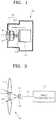
- FIG. 1is a conceptual view illustrating a structure of a 3D image acquisition apparatus 100, according to an example not belonging to the invention.
- the 3D image acquisition apparatus 100includes an objective lens 111 for focusing light reflected off an external object (not shown), an image processing unit 130 for processing the light focused by the objective lens 111 to generate an image signal, an illumination optical system 120 for illuminating the object to acquire depth information about the object, and a control unit 140 for controlling the operations of the objective lens 111, the image processing unit 130, and the illumination optical system 120.
- the illumination optical system 120may irradiate illumination light, for example, infrared rays, onto the object.
- the infrared illumination light reflected off the objectis focused on the image processing unit 130 by the objective lens 111.
- external visible light reflected off the objectmay be focused on the image processing unit 130.
- the image processing unit 130may generate a depth image signal for calculating the depth information about the object by modulating the illumination light using TOF technology.
- the image processing unit 130may generate a standard color (RGB) image signal by using the visible light.
- the control unit 140may calculate the depth information about the object using the generated depth image signal and the RGB image signal to generate an image for a user.
- the illumination optical system 120 for illuminating the objectmay be integrated with the objective lens 111, which forms an imaging optical system for imaging the object, into one optical system 110. That is, as illustrated in FIG. 1 , the illumination optical system 120 and the objective lens 111 may be disposed such that axes thereof are coaxial. When the optical axis of the illumination optical system 120 and the optical axis of the objective lens 111 coincide with each other, parallax will not occur between the optical illumination system 120 and the objective lens 111.
- the illumination light irradiated from the illumination optical system 120may travel along the optical axis of the objective lens 111 to illuminate the object, reflect off the object, and then travel along the optical axis of the objective lens 111 to be focused on the image processing unit 130 by the objective lens 111.
- the matching paths of the irradiated illumination light and the reflected illumination lightmay allow depth information regarding a distance between the object and the 3D image acquisition apparatus 100 to be precisely calculated.
- a relatively great portion of the illumination light scattered and reflected off the objectmay be incident back on the objective lens 111, and thus utilization efficiency of the illumination light may be improved. This may increase the amount of the illumination light collected by the image processing unit 130, thus further improving the precision of the depth information about the object.
- FIG. 2illustrates a detailed structure of the optical system 110 in which the objective lens 111 as the imaging optical system and the illumination optical system 120 are coaxially integrated on an optical axis OX, according to an exemplary embodiment.
- the optical system 110may include an imaging objective lens 111 having an aperture 115 in a center region thereof where the optical axis OX passes, an illumination objective lens 122 disposed within the aperture 115 of the imaging objective lens 111, and a light source 121 that provides illumination light to the illumination objective lens 122.
- the imaging objective lens 111 and the illumination objective lens 122are coaxially disposed with the optical axis OX passing centers thereof. Accordingly, the optical axis of the imaging objective lens 111 and the optical axis of the objective lens 122 may coincide with each other.
- each of the imaging objective lens 111 and the illumination objective lens 122are illustrated as one lens in FIG. 2 for convenience of illustration, the imaging objective lens 111 and the illumination objective lens 122 may each be, for example, a variable-magnification zoom lens including a plurality of lenses. Zoom magnifications of the imaging objective lens 111 and the illumination objective lens 122 may be synchronously controlled. In one embodiment, the control unit 140 may simultaneously control the imaging objective lens 111 and the illumination objective lens 122 to have the same zoom magnification.
- the light source 121may include an LED or an LD that emits light having an invisible near infrared wavelength of about 850 nm, for the safety of a user.
- the light source 121may emit light having a specifically defined waveform, for example, a sign wave, a lamp wave, or a square wave, according to a control signal received from the control unit 140.
- the light source 121may be located on the common optical axis of the imaging objective lens 111 and the illumination objective lens 122.
- the light source 121may be located between the imaging objective lens 111 and the illumination objective lens 122, and the image processing unit 130.
- the light source 121 and the illumination objective lens 122together may form the illumination optical system 120. Accordingly, after being incident on the illumination objective lens 122, infrared light emitted from the light source 121 may be projected onto the object via the illumination objective lens 122.
- the light source 121may be located on a focal plane of the illumination objective lens 122.
- the light source 121may be located on a non-focal plane of the imaging objective lens 111.
- a light component that is incident on the light source 121may be blurred, and thus the light source 121 may be almost or completely not seen by an imaging device 135 (see FIG. 3 ) of the image processing unit 130.
- the light source 121may not influence imaging by the imaging device 135.
- the image processing unit 130may include an additional optical structure.
- FIG. 3exemplarily illustrates a structure of the image processing unit 130.
- the image processing unit 130may include a collective lens 131, a first relay lens 132, an optical modulator 133, a second relay lens 134, and the imaging device 135 sequentially in a direction in which light travels.
- the collective lens 131may allow only light passing through a region of the imaging objective lens 111 to enter the imaging device 135.
- the collective lens 131may prevent the light source 121 from obstructing imaging.
- the light source 121may be disposed on a non-focal plane of the collective lens 131.
- the collective lens 131may be an aspheric lens that blocks a light portion passing through the light source 121, allowing only the rest of the light to be focused on the imaging device 135.
- an iris 136may be further disposed in front of the collective lens 131 with respect to the direction in which light travels.
- the iris 136 in FIG. 3is a ring type with an aperture in a center thereof, a disk type iris without an aperture may be used.
- the iris 136is disposed in front of the collective lens 131 in FIG. 3 with respect to the direction in which light travels, the location of the iris 136 is not specifically limited.
- the iris 136may be disposed between the collective lens 131 and the first relay lens 132.
- the first relay lens 132focuses light on the optical modulator 133.
- the second relay lens 134focuses light modulated by the optical modulator 133 on the imaging device 135.
- the optical modulator 133modulates incident light to have a predetermined gain waveform according to TOF technology to obtain the depth information about the object.
- the gain waveform obtained by the optical modulator 133may be determined, for example, according to a control of the control unit 140.
- the imaging device 135generates an electric image signal by sensing the light modulated by the optical modulator 133.
- the imaging device 135may be a semiconductor imaging device, for example, an imaging charge-coupled device (CCD) or a complementary metal oxide semiconductor (CMOS) imaging device.
- CCDimaging charge-coupled device
- CMOScomplementary metal oxide semiconductor
- FIG. 4illustrates a structure of an optical system 110a using one common objective lens.
- the optical system 110amay include one common objective lens 112, the light source 121 disposed on the optical axis OX between the common objective lens 112 and the image processing unit 130, and a matching lens 123 disposed between the light source 121 and the common objective lens 112.
- the common objective lens 112may be a variable-magnification zoom lens including a plurality of lenses. If the common objective lens 112 is a zoom lens, a zoom magnification of the illumination optical system and the imaging optical system may remain constant without an additional precise control mechanism.
- the elements of the optical system 110a not described above and operations thereofmay be identical to those of the optical system 110 of FIG. 2 . That is, the light source 121 may be located on a non-focal plane of the common objective lens 112. In this case, infrared light emitted from the light source 121 may not be projected precisely toward the object.
- the matching lens 123optically matches the light source 121 to a central region of the common objective lens 112. By using the matching lens 123, the infrared light emitted from the light source 121 may be projected accurately onto the object via the central region of the common objective lens 112. Thus, a field of illumination of the optical system 110a may accurately coincide with a field of view of the 3D image acquisition apparatus 100.
- FIG. 5is a schematic conceptual view illustrating a structure of an optical system 110b, according to another exemplary embodiment.
- the optical system 110bmay include the imaging objective lens 111 with the aperture 115 in the center thereof through which the optical axis OX passes, a plane mirror 124 located on the optical axis OX to correspond to the aperture 115, the light source 121 disposed off the optical axis OX to emit light toward the plane mirror 124, and the illumination objective lens 122 disposed between the light source 121 and the plane mirror 124.
- a flat transparent window 116may be further disposed within the aperture 115 of the imaging objective lens 111.
- the plane mirror 124may be disposed where the light source 121 is located in FIG. 2 . That is, the plane mirror 124 may be disposed on a non-focal plane of the imaging objective lens 111 between the imaging objective lens 111 and the image processing unit 130. As illustrated in FIG. 5 , the plane mirror 124 may be disposed at an incline on the optical axis OX to reflect illumination light incident thereon from the light source 121 toward the aperture 115 of the imaging objective lens 111. Therefore, the plane mirror 124 may align the illumination light from the light source 121, which is disposed off the optical axis OX, with the optical axis OX.
- the illumination objective lens 122is disposed within the aperture 115 of the imaging objective lens 111, while in the embodiment of FIG. 5 , the illumination objective lens 122 is disposed between the light source 121 and the plane mirror 124 off the optical axis OX.
- the locations of the light source 121 and the objective lens 122 off the optical axis OXmay lead to an increased degree of freedom in sizing and designing the light source 121, the illumination objective lens 122, and the imaging objective lens 111.
- the location of the plane mirror 124which is smaller in volume relative to the light source 121, on the optical axis OX may less likely obstruct imaging in the image processing unit 130. Accordingly, designing the collective lens 131 of the image processing unit 130 may be facilitated. In another embodiment, the collective lens 131 and the iris 136 may be omitted.
- FIG. 6is a conceptual view illustrating a structure of an optical system 110c.
- the optical system 110cmay include the common objective lens 112, the plane mirror 124 disposed on the optical axis OX between the common objective lens 112 and the image processing unit 130, the light source 121 disposed off the optical axis OX to emit light toward the plane mirror 124, and the matching lens 123 disposed between the light source 121 and the plane mirror 124.
- the common objective lens 112is a zoom lens
- a zoom magnification of the illumination optical system and the imaging optical systemmay remain constant without an additional control mechanism.
- the plane mirror 124may be located on a non-focal plane of the common objective lens 112.
- the matching lens 123may adjust a beam diameter of illumination light emitted from the light source 121 to be wholly incident on the plane mirror 124.
- the matching lens 123may optically match the light source 121 to the central region of the common objective lens 112 to enable the illumination light to be accurately projected onto the object via the central region of the common objective lens 112.
- FIG. 7is a conceptual view illustrating a structure of an optical system 110d.
- the optical system 110dmay include the imaging objective lens 111 with the aperture 115 in the center thereof through which the optical axis OX passes, the illumination objective lens 122 disposed within the aperture 115 of the imaging objective lens 111, the plane mirror 124 located on the optical axis OX to correspond to the aperture 115, the light source 121 disposed off the optical axis OX to emit light toward the plane mirror 124, and the matching lens 123 disposed between the light source 121 and the plane mirror 124.
- the descriptions of the imaging objective lens 111 and the illumination objective lens 122 with reference to FIG. 2may apply to those of FIG. 7 .
- the descriptions of the plane mirror 124 and the light source 121 with reference to FIG. 5may apply to those of FIG. 7 .
- the matching lens 123may adjust a beam diameter of illumination light emitted from the light source 121 to be wholly incident on the plane mirror 124.
- the matching lens 123may also serve as a relay lens for matching a focal point of the illumination objective lens 122 to the light source 121.
- FIG. 8is a conceptual view illustrating a structure of an optical system 110e.
- the optical system 110emay include the imaging objective lens 111 with the aperture 115 in the center thereof through which the optical axis OX passes, the illumination objective lens 122 disposed within the aperture 115 of the imaging objective lens 111, a curved mirror 125 located on the optical axis OX to correspond to the aperture 115, and the light source 121 disposed off the optical axis OX to emit light toward the curved mirror 125.
- the descriptions of the imaging objective lens 111 and the illumination objective lens 122 with reference to FIG. 2may apply to those of FIG. 8 .
- the curved mirror 125may be disposed on a non-focal plane of the imaging objective lens 111 on the optical axis OX between the imaging objective lens 111 and the image processing unit 130. As illustrated in FIG. 8 , the curved mirror 125 may be a convex mirror having a convex reflecting surface. Accordingly, condensed illumination light having a relatively small beam diameter may be emitted from the light source 121 to the curved mirror 125. To this end, a light transmission member 126, for example, an optical fiber, may be used to transmit the illumination light from the light source 121 to the curved mirror 125.
- the illumination lightmay be projected directly from the light source 121 toward the curved mirror 125 by using an appropriate collimating element.
- the illumination light emitted from the light source 121may diverge at an angle by reflecting off the curved mirror 125.
- the illumination light reflected off the curved mirror 125may be projected onto the object via the illumination objective lens 122.
- the curved mirror 125may serve as the matching lens 123 of FIG. 7 .
- the matching lens 123 of FIG. 7 for optical matching with the illumination objective lens 122may be omitted.
- the curved mirror 125may be a concave mirror having a concave reflecting surface. For example, when illumination light diverging at an angle, instead of the condensed illumination light having a relatively small beam diameter, is used, the illumination light may be adjusted to be incident on only the illumination objective lens 122 by using the curved mirror having the concave reflecting surface.
- FIG. 9is a conceptual view illustrating a structure of an optical system 100f, according to another exemplary embodiment.
- the optical system 100fmay include the imaging objective lens 111 with the aperture 115 in the center thereof through which the optical axis OX passes, the curved mirror 125 located on the optical axis OX to correspond to the aperture 115, and the light source 121 disposed off the optical axis OX to emit light toward the curved mirror 125.
- the flat transparent window 116 having zero curvaturemay be further disposed within the aperture 115 of the imaging objective lens 111.
- condensed illumination light having a relatively small beam diametermay be transmitted from the light source 121 to the curved mirror 125 by using the light transmission member 126, which may be an optical fiber.
- the curved mirror 125 having the convex reflecting surfacemay reflect the illumination light to diverge the illumination light at a constant angle.
- the illumination light reflected off the curved mirror 125may be projected directly onto the object through the transparent window 116. Accordingly, the illumination objective lens 122 may be unnecessary, and the imaging objective lens 111 may be a short focus lens having a fixed magnification corresponding to the curvature of the curved mirror 125.
- a field of illumination of the illumination optical system 120may be matched with a field of view of the 3D image acquisition apparatus 100.
- the field of view of the 3D image acquisition apparatus 100may be rectangular with an aspect ratio of about 4:3, while a cross-section (i.e., the field of illumination) of the illumination light is circular.
- a portion of the illumination lightmay not be used to obtain the depth information. This may reduce the utilization efficiency of the illumination light. Therefore, when the cross-section of the illumination light is made to be rectangular with an aspect ratio of about 4:3, which is equal to that of the field of view of the 3D image acquisition apparatus 100, the utilization efficiency of the illumination light may be improved.
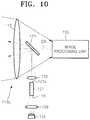
- FIG. 10is a schematic view illustrating a structure of an optical system 110g, illustrating the use of a beam shaping element disposed between the mirror and the light source for the present invention.
- the optical system 110gmay include the common objective lens 112, the plane mirror 124 disposed on the optical axis OX between the common objective lens 112 and the image processing unit 130, the light source 121 disposed off the optical axis OX to emit illumination light toward the plane mirror 124, a beam shaping element 127 disposed between the light source 121 and the plane mirror 124, a first matching lens 123 disposed between the plane mirror 124 and the beam shaping element 127 to match the illumination light emitted from the beam shaping element 127 to the center region of the common objective lens 112, and a second matching lens 128 disposed between the light source 121 and the beam shaping element 127 to project the illumination light emitted from the light source 121 onto the beam shaping element 127.
- the beam shaping element 127uniformly homogenizes the illumination light emitted from the light source 121 and changes a cross-sectional shape of the illumination light to a predetermined shape.
- the beam shaping element 127may change the cross-sectional shape of the illumination light to be rectangular with an aspect ratio of about 4:3.
- the beam shaping element 127may be an integrator rod made of a transparent material, for example, glass or a light-transmitting plastic, and having a rectangular cross-section.
- a light-incidence surface 127i and a light-exit surface 127e of the beam shaping element 127may each have an anti-reflection coating to reduce light loss due to reflection.
- a circumferential surface of the beam shaping element 127may have a high-reflectivity coating.
- the illumination light incident on the light-incidence surface 127iundergoes total internal reflection while traveling in the beam shaping element 127, and emerges from the beam shaping element 127 through the light-exit surface 127e.
- the illumination light emitted from the light-exit surface 127emay have a rectangular cross-section that is identical to that of the beam shaping element 127. Therefore, the field of illumination of the illumination optical system 120 may coincide with the field of view of the 3D image acquisition apparatus 100. While undergoing total continuous reflection in the beam shaping element 127, light beams traveling along various paths are mixed together, homogenizing light intensity across the whole cross-section of illumination. Consequently, the light intensity may be substantially the same at any spot within the field of illumination.
- the beam shaping element 127is used along with one common objective lens 112
- the beam shaping element 127is used along with the imaging objective lens 111 (see FIG. 5 and 9 ) with the aperture 115 in the center region thereof through which the optical axis OX passes, and as illustrated in FIG. 5 , the transparent window 116 being disposed within the aperture 115 of the imaging objective lens 111, and the illumination objective lens 122 may be disposed where the first matching lens 123 is located in FIG. 10 .
- the curved mirror 125(see FIG. 9 ) may be used instead of the plane mirror 124.
Landscapes
- Physics & Mathematics (AREA)
- General Physics & Mathematics (AREA)
- Optics & Photonics (AREA)
- Engineering & Computer Science (AREA)
- Multimedia (AREA)
- Signal Processing (AREA)
- Length Measuring Devices By Optical Means (AREA)
- Microscoopes, Condenser (AREA)
- Testing, Inspecting, Measuring Of Stereoscopic Televisions And Televisions (AREA)
- Studio Devices (AREA)
- Investigating Or Analysing Materials By Optical Means (AREA)
- Stroboscope Apparatuses (AREA)
- Stereoscopic And Panoramic Photography (AREA)
- Non-Portable Lighting Devices Or Systems Thereof (AREA)
Description
- Apparatuses consistent with exemplary embodiments related to an optical system in which an illumination optical system and an imaging optical system are integrated to have a coaxial optical axis in order to obtain more precise depth information, and a three-dimensional (3D) image acquisition apparatus including the optical system.
- With recent advances in 3D display apparatuses and increasing demand therefor, the significance of 3D content in which depth can be perceived is becoming important. Accordingly, research into 3D image acquisition apparatuses such as 3D cameras that enable users to create 3D content on their own is increasing. 3D cameras need to have a function through which depth information along with common 2D color image information are acquired through one photographing operation.
- Depth information indicating distances between the 3D camera and surfaces of an object may be acquired using stereo vision methods that use two cameras, or using triangulation methods that use structured light and a camera. However, according to these methods, the greater the camera-to-object distance, the more imprecise the obtained depth information becomes, and these methods are highly dependent on the surface states of objects. Thus, acquiring precise depth information with these methods is difficult.
- To address these problems, Time-of-Flight (TOF) techniques have been introduced. TOF techniques measure a travel time of illumination light reflecting off an object after having been irradiated thereon to a light receiving unit for receiving the illumination light. TOF technology involves irradiating light having a specific wavelength (for example, near infrared rays having a wavelength of 850 nm) onto an object by using an illumination optical system that includes a light emitting diode (LED) or a laser diode (LD), receiving the light with a light receiving unit after the light is reflected off the object, and a series of process for extracting depth information, for example, by modulating the received light using a modulator with a known gain wavelength. Various TOF technologies for the series of processes are available.
- In measuring distance using light reflected off an object after having been projected from an illumination optical system, the greater an amount of the reflected light that is incident on a 3D camera, the more precise obtained depth information becomes. This is because in signal processing for extracting depth information using a 3D camera, a signal-to-noise ratio is proportional to an amount of incident light, and the greater the signal-to-noise ratio, the more precise obtained depth information becomes. Therefore, an optical system needs to be designed to provide a 3D camera which receives as much incident light as possible.
- A 3D camera adopting TOF technology includes, in general, an illumination optical system that emits illumination light for acquiring depth information, and an imaging optical system for acquiring an image of an object. However, since the illumination optical system and the imaging optical system are separate systems, they have optical axes that do not match. Accordingly, parallax occurs between the illumination optical system and the imaging optical system. This may cause obtained depth information about an object to be imprecise, lowering utilization efficiency of illumination light.
US2002/0183626 A1 relates to systems and methods for examining a sample using a substantially monostatic, substantially confocal optical system comprising transmitting optics that collect light emitted from the sample following illumination thereof. In certain embodiments, the receiving optics may be arranged circumferentially around the light path traversed by the illuminating light. In certain embodiments, video apparatus may be included to produce images or to align the system in proximity to the target tissue. The systems and methods of the invention according to this document may be directed towards the examination of a body tissue to provide a medical diagnosis.DE 199 07 546 A1 relates to an optic electronic device for the capturing of objects in a monitoring area via a light transmitter.WO 03/073123 A1 DE 10 2004 038 940 A1 relates to an optic electronic device for the capturing of objects in a monitoring area via a light transmitter.- It is therefore the object of the invention to provide an improved optical system of a three-dimensional image acquisition apparatus and an improved three-dimensional image acquisition apparatus.
- This object is solved by the subject matter of the independent claim. Preferred embodiments are defined by the dependent claims.
- Additional aspects will be set forth in part in the description which follows and, in part, will be apparent from the description, or may be learned by practice of the presented embodiments.
- These and/or other aspects will become apparent and more readily appreciated from the following description of exemplary embodiments, taken in conjunction with the accompanying drawings of which:
FIG. 1 is a conceptual view illustrating a structure of a 3D image acquisition apparatus, according to an exemplary embodiment;FIG. 2 is a schematic conceptual view illustrating a detailed structure of an integrated optical system inFIG. 1 , according to an example not belonging to the invention;FIG. 3 is a schematic conceptual view illustrating a structure of an image processing unit ofFIGS. 1 and 2 , according to an exemplary embodiment;FIG. 4 is a schematic conceptual view illustrating a structure of an optical system, according to another example not belonging to the invention;FIG. 5 is a schematic conceptual view illustrating a structure of an optical system, according to another exemplary embodiment;FIG. 6 is a schematic conceptual view illustrating a structure of an optical system, according to another example not belonging to the invention;FIG. 7 is a schematic conceptual view illustrating a structure of an optical system, according to another example not belonging to the invention;FIG. 8 is a schematic conceptual view illustrating a structure of an optical system, according to another example not belonging to the invention;FIG. 9 is a schematic conceptual view illustrating a structure of an optical system, according to another exemplary embodiment; andFIG. 10 is a schematic conceptual view illustrating a structure of an optical system, showing a beam shaping element.- Reference will now be made in detail to exemplary embodiments of an optical system having integrated illumination and imaging optical systems, and a 3D image acquisition apparatus including the optical system, examples of which are illustrated in the accompanying drawings. In the drawings, like reference numerals in the drawings denote like elements, and the size of each component may be exaggerated for clarity.
FIG. 1 is a conceptual view illustrating a structure of a 3Dimage acquisition apparatus 100, according to an example not belonging to the invention. Referring toFIG. 1 , the 3Dimage acquisition apparatus 100 includes anobjective lens 111 for focusing light reflected off an external object (not shown), animage processing unit 130 for processing the light focused by theobjective lens 111 to generate an image signal, an illuminationoptical system 120 for illuminating the object to acquire depth information about the object, and acontrol unit 140 for controlling the operations of theobjective lens 111, theimage processing unit 130, and the illuminationoptical system 120.- The illumination
optical system 120 may irradiate illumination light, for example, infrared rays, onto the object. The infrared illumination light reflected off the object is focused on theimage processing unit 130 by theobjective lens 111. Simultaneously, external visible light reflected off the object may be focused on theimage processing unit 130. Theimage processing unit 130 may generate a depth image signal for calculating the depth information about the object by modulating the illumination light using TOF technology. Theimage processing unit 130 may generate a standard color (RGB) image signal by using the visible light. Thecontrol unit 140 may calculate the depth information about the object using the generated depth image signal and the RGB image signal to generate an image for a user. - According to one embodiment, the illumination
optical system 120 for illuminating the object may be integrated with theobjective lens 111, which forms an imaging optical system for imaging the object, into oneoptical system 110. That is, as illustrated inFIG. 1 , the illuminationoptical system 120 and theobjective lens 111 may be disposed such that axes thereof are coaxial. When the optical axis of the illuminationoptical system 120 and the optical axis of theobjective lens 111 coincide with each other, parallax will not occur between theoptical illumination system 120 and theobjective lens 111. Accordingly, the illumination light irradiated from the illuminationoptical system 120 may travel along the optical axis of theobjective lens 111 to illuminate the object, reflect off the object, and then travel along the optical axis of theobjective lens 111 to be focused on theimage processing unit 130 by theobjective lens 111. The matching paths of the irradiated illumination light and the reflected illumination light may allow depth information regarding a distance between the object and the 3Dimage acquisition apparatus 100 to be precisely calculated. Furthermore, a relatively great portion of the illumination light scattered and reflected off the object may be incident back on theobjective lens 111, and thus utilization efficiency of the illumination light may be improved. This may increase the amount of the illumination light collected by theimage processing unit 130, thus further improving the precision of the depth information about the object. FIG. 2 illustrates a detailed structure of theoptical system 110 in which theobjective lens 111 as the imaging optical system and the illuminationoptical system 120 are coaxially integrated on an optical axis OX, according to an exemplary embodiment. Referring toFIG. 2 , theoptical system 110 may include an imagingobjective lens 111 having anaperture 115 in a center region thereof where the optical axis OX passes, an illuminationobjective lens 122 disposed within theaperture 115 of the imagingobjective lens 111, and alight source 121 that provides illumination light to the illuminationobjective lens 122. As illustrated inFIG. 2 , the imagingobjective lens 111 and the illuminationobjective lens 122 are coaxially disposed with the optical axis OX passing centers thereof. Accordingly, the optical axis of theimaging objective lens 111 and the optical axis of theobjective lens 122 may coincide with each other.- Although each of the
imaging objective lens 111 and theillumination objective lens 122 are illustrated as one lens inFIG. 2 for convenience of illustration, theimaging objective lens 111 and theillumination objective lens 122 may each be, for example, a variable-magnification zoom lens including a plurality of lenses. Zoom magnifications of theimaging objective lens 111 and theillumination objective lens 122 may be synchronously controlled. In one embodiment, thecontrol unit 140 may simultaneously control theimaging objective lens 111 and theillumination objective lens 122 to have the same zoom magnification. - In some embodiments, the
light source 121 may include an LED or an LD that emits light having an invisible near infrared wavelength of about 850 nm, for the safety of a user. However, this is only exemplary, and light having any appropriate wavelength and various kinds of light sources may be used. Thelight source 121 may emit light having a specifically defined waveform, for example, a sign wave, a lamp wave, or a square wave, according to a control signal received from thecontrol unit 140. - As illustrated in
FIG. 2 , thelight source 121 may be located on the common optical axis of theimaging objective lens 111 and theillumination objective lens 122. Thelight source 121 may be located between the imagingobjective lens 111 and theillumination objective lens 122, and theimage processing unit 130. Thelight source 121 and theillumination objective lens 122 together may form the illuminationoptical system 120. Accordingly, after being incident on theillumination objective lens 122, infrared light emitted from thelight source 121 may be projected onto the object via theillumination objective lens 122. To this end, thelight source 121 may be located on a focal plane of theillumination objective lens 122. - Meanwhile, light reflected off the object and incident on the 3D
image acquisition apparatus 100 is focused on theimage processing unit 130 via theimaging objective lens 111. In this regard, to prevent thelight source 121 located on the optical axis OX between the imagingobjective lens 111 and theimage processing unit 130 from blocking the light that is to enter theimage processing unit 130, thelight source 121 may be located on a non-focal plane of theimaging objective lens 111. When thelight source 121 is located on a non-focal plane of theimaging objective lens 111, a light component that is incident on thelight source 121 may be blurred, and thus thelight source 121 may be almost or completely not seen by an imaging device 135 (seeFIG. 3 ) of theimage processing unit 130. Thus, even though thelight source 121 is located between the imagingobjective lens 111 and theimage processing unit 130, thelight source 121 may not influence imaging by theimaging device 135. - To further diminish interference by the
light source 121, theimage processing unit 130 may include an additional optical structure.FIG. 3 exemplarily illustrates a structure of theimage processing unit 130. Referring toFIG. 3 , theimage processing unit 130 may include acollective lens 131, afirst relay lens 132, anoptical modulator 133, asecond relay lens 134, and theimaging device 135 sequentially in a direction in which light travels. To prevent light passing through thelight source 121 from being detected by theimaging device 135, thecollective lens 131 may allow only light passing through a region of theimaging objective lens 111 to enter theimaging device 135. Thus, thecollective lens 131 may prevent thelight source 121 from obstructing imaging. To this end, thelight source 121 may be disposed on a non-focal plane of thecollective lens 131. Thecollective lens 131 may be an aspheric lens that blocks a light portion passing through thelight source 121, allowing only the rest of the light to be focused on theimaging device 135. To further block, for example, scattered light that may be generated by thelight source 121, aniris 136 may be further disposed in front of thecollective lens 131 with respect to the direction in which light travels. Although theiris 136 inFIG. 3 is a ring type with an aperture in a center thereof, a disk type iris without an aperture may be used. Although theiris 136 is disposed in front of thecollective lens 131 inFIG. 3 with respect to the direction in which light travels, the location of theiris 136 is not specifically limited. In another embodiment, theiris 136 may be disposed between thecollective lens 131 and thefirst relay lens 132. - The
first relay lens 132 focuses light on theoptical modulator 133. Thesecond relay lens 134 focuses light modulated by theoptical modulator 133 on theimaging device 135. Theoptical modulator 133 modulates incident light to have a predetermined gain waveform according to TOF technology to obtain the depth information about the object. The gain waveform obtained by theoptical modulator 133 may be determined, for example, according to a control of thecontrol unit 140. Theimaging device 135 generates an electric image signal by sensing the light modulated by theoptical modulator 133. In some embodiments theimaging device 135 may be a semiconductor imaging device, for example, an imaging charge-coupled device (CCD) or a complementary metal oxide semiconductor (CMOS) imaging device. - Although the
imaging objective lens 111 and theillumination objective lens 122 are illustrated as different lenses inFIG. 2 , one common objective lens may function as both theimaging objective lens 111 and theillumination objective lens 122.FIG. 4 illustrates a structure of anoptical system 110a using one common objective lens. Referring toFIG. 4 , theoptical system 110a may include one commonobjective lens 112, thelight source 121 disposed on the optical axis OX between the commonobjective lens 112 and theimage processing unit 130, and a matchinglens 123 disposed between thelight source 121 and the commonobjective lens 112. As described above, although illustrated as one lens inFIG. 4 for convenience of illustration, the commonobjective lens 112 may be a variable-magnification zoom lens including a plurality of lenses. If the commonobjective lens 112 is a zoom lens, a zoom magnification of the illumination optical system and the imaging optical system may remain constant without an additional precise control mechanism. - The elements of the
optical system 110a not described above and operations thereof may be identical to those of theoptical system 110 ofFIG. 2 . That is, thelight source 121 may be located on a non-focal plane of the commonobjective lens 112. In this case, infrared light emitted from thelight source 121 may not be projected precisely toward the object. The matchinglens 123 optically matches thelight source 121 to a central region of the commonobjective lens 112. By using thematching lens 123, the infrared light emitted from thelight source 121 may be projected accurately onto the object via the central region of the commonobjective lens 112. Thus, a field of illumination of theoptical system 110a may accurately coincide with a field of view of the 3Dimage acquisition apparatus 100. - To further diminish interference by the
light source 121, thelight source 121 may be located off the optical axis (OX), and a small mirror may be disposed on the optical axis OX.FIG. 5 is a schematic conceptual view illustrating a structure of anoptical system 110b, according to another exemplary embodiment. Referring toFIG. 5 , theoptical system 110b may include theimaging objective lens 111 with theaperture 115 in the center thereof through which the optical axis OX passes, aplane mirror 124 located on the optical axis OX to correspond to theaperture 115, thelight source 121 disposed off the optical axis OX to emit light toward theplane mirror 124, and theillumination objective lens 122 disposed between thelight source 121 and theplane mirror 124. To prevent external harmful components such as dust and moisture from entering the 3Dimage acquisition apparatus 100 through theaperture 115, a flattransparent window 116 may be further disposed within theaperture 115 of theimaging objective lens 111. - The
plane mirror 124 may be disposed where thelight source 121 is located inFIG. 2 . That is, theplane mirror 124 may be disposed on a non-focal plane of theimaging objective lens 111 between the imagingobjective lens 111 and theimage processing unit 130. As illustrated inFIG. 5 , theplane mirror 124 may be disposed at an incline on the optical axis OX to reflect illumination light incident thereon from thelight source 121 toward theaperture 115 of theimaging objective lens 111. Therefore, theplane mirror 124 may align the illumination light from thelight source 121, which is disposed off the optical axis OX, with the optical axis OX. - In
FIG. 2 , theillumination objective lens 122 is disposed within theaperture 115 of theimaging objective lens 111, while in the embodiment ofFIG. 5 , theillumination objective lens 122 is disposed between thelight source 121 and theplane mirror 124 off the optical axis OX. The locations of thelight source 121 and theobjective lens 122 off the optical axis OX may lead to an increased degree of freedom in sizing and designing thelight source 121, theillumination objective lens 122, and theimaging objective lens 111. Furthermore, the location of theplane mirror 124, which is smaller in volume relative to thelight source 121, on the optical axis OX may less likely obstruct imaging in theimage processing unit 130. Accordingly, designing thecollective lens 131 of theimage processing unit 130 may be facilitated. In another embodiment, thecollective lens 131 and theiris 136 may be omitted. - The common
objective lens 122 ofFIG. 4 may be used along with theplane mirror 124.FIG. 6 is a conceptual view illustrating a structure of anoptical system 110c. Referring toFIG. 6 , theoptical system 110c may include the commonobjective lens 112, theplane mirror 124 disposed on the optical axis OX between the commonobjective lens 112 and theimage processing unit 130, thelight source 121 disposed off the optical axis OX to emit light toward theplane mirror 124, and the matchinglens 123 disposed between thelight source 121 and theplane mirror 124. As described above, if the commonobjective lens 112 is a zoom lens, a zoom magnification of the illumination optical system and the imaging optical system may remain constant without an additional control mechanism. - As in the embodiment of
FIG. 5 , theplane mirror 124 may be located on a non-focal plane of the commonobjective lens 112. The matchinglens 123 may adjust a beam diameter of illumination light emitted from thelight source 121 to be wholly incident on theplane mirror 124. The matchinglens 123 may optically match thelight source 121 to the central region of the commonobjective lens 112 to enable the illumination light to be accurately projected onto the object via the central region of the commonobjective lens 112. - If the
plane mirror 124 is used, theillumination objective lens 122 may be disposed within theaperture 115 of theimaging objective lens 111 as inFIG. 2 .FIG. 7 is a conceptual view illustrating a structure of anoptical system 110d. Referring toFIG. 7 , theoptical system 110d may include theimaging objective lens 111 with theaperture 115 in the center thereof through which the optical axis OX passes, theillumination objective lens 122 disposed within theaperture 115 of theimaging objective lens 111, theplane mirror 124 located on the optical axis OX to correspond to theaperture 115, thelight source 121 disposed off the optical axis OX to emit light toward theplane mirror 124, and the matchinglens 123 disposed between thelight source 121 and theplane mirror 124. The descriptions of theimaging objective lens 111 and theillumination objective lens 122 with reference toFIG. 2 may apply to those ofFIG. 7 . The descriptions of theplane mirror 124 and thelight source 121 with reference toFIG. 5 may apply to those ofFIG. 7 . The matchinglens 123 may adjust a beam diameter of illumination light emitted from thelight source 121 to be wholly incident on theplane mirror 124. The matchinglens 123 may also serve as a relay lens for matching a focal point of theillumination objective lens 122 to thelight source 121. - Although the
plane mirror 124 with a flat reflecting surface is used inFIG. 5 and7 , a curved mirror with a reflecting surface having a curvature may also be used instead of theplane mirror 124.FIG. 8 is a conceptual view illustrating a structure of anoptical system 110e. Referring toFIG. 8 , theoptical system 110e may include theimaging objective lens 111 with theaperture 115 in the center thereof through which the optical axis OX passes, theillumination objective lens 122 disposed within theaperture 115 of theimaging objective lens 111, acurved mirror 125 located on the optical axis OX to correspond to theaperture 115, and thelight source 121 disposed off the optical axis OX to emit light toward thecurved mirror 125. The descriptions of theimaging objective lens 111 and theillumination objective lens 122 with reference toFIG. 2 may apply to those ofFIG. 8 . - Similar to the
plane mirror 124, thecurved mirror 125 may be disposed on a non-focal plane of theimaging objective lens 111 on the optical axis OX between the imagingobjective lens 111 and theimage processing unit 130. As illustrated inFIG. 8 , thecurved mirror 125 may be a convex mirror having a convex reflecting surface. Accordingly, condensed illumination light having a relatively small beam diameter may be emitted from thelight source 121 to thecurved mirror 125. To this end, alight transmission member 126, for example, an optical fiber, may be used to transmit the illumination light from thelight source 121 to thecurved mirror 125. When thelight transmission member 126, for example, an optical fiber, is used, an optical path from thelight source 121 to thecurved mirror 125 does not need to be straight, which may improve internal space utilization efficiency of the 3Dimage acquisition apparatus 100 including theoptical system 110e. However, in another embodiment, the illumination light may be projected directly from thelight source 121 toward thecurved mirror 125 by using an appropriate collimating element. - When the convex
curved mirror 125 is used, the illumination light emitted from thelight source 121 may diverge at an angle by reflecting off thecurved mirror 125. The illumination light reflected off thecurved mirror 125 may be projected onto the object via theillumination objective lens 122. When the curvature of the reflecting surface of thecurved mirror 125 is appropriately selected, thecurved mirror 125 may serve as the matchinglens 123 ofFIG. 7 . Thus, when thecurved mirror 125 is used, the matchinglens 123 ofFIG. 7 for optical matching with theillumination objective lens 122 may be omitted. Thecurved mirror 125 may be a concave mirror having a concave reflecting surface. For example, when illumination light diverging at an angle, instead of the condensed illumination light having a relatively small beam diameter, is used, the illumination light may be adjusted to be incident on only theillumination objective lens 122 by using the curved mirror having the concave reflecting surface. - Although serving only as a matching lens in
FIG. 8 , thecurved mirror 125 may also work as theillumination objective lens 122 for projecting illumination light onto the object.FIG. 9 is a conceptual view illustrating a structure of an optical system 100f, according to another exemplary embodiment. Referring toFIG. 9 , the optical system 100f may include theimaging objective lens 111 with theaperture 115 in the center thereof through which the optical axis OX passes, thecurved mirror 125 located on the optical axis OX to correspond to theaperture 115, and thelight source 121 disposed off the optical axis OX to emit light toward thecurved mirror 125. To prevent external harmful components such as dust and moisture from entering the 3Dimage acquisition apparatus 100 through theaperture 115, the flattransparent window 116 having zero curvature may be further disposed within theaperture 115 of theimaging objective lens 111. - As described above, condensed illumination light having a relatively small beam diameter may be transmitted from the
light source 121 to thecurved mirror 125 by using thelight transmission member 126, which may be an optical fiber. Thecurved mirror 125 having the convex reflecting surface may reflect the illumination light to diverge the illumination light at a constant angle. When the curvature of thecurved mirror 125 is appropriately selected, the illumination light reflected off thecurved mirror 125 may be projected directly onto the object through thetransparent window 116. Accordingly, theillumination objective lens 122 may be unnecessary, and theimaging objective lens 111 may be a short focus lens having a fixed magnification corresponding to the curvature of thecurved mirror 125. - To further increase utilization efficiency of illumination light in order to obtain more precise depth information about the object, a field of illumination of the illumination
optical system 120 may be matched with a field of view of the 3Dimage acquisition apparatus 100. In general, the field of view of the 3Dimage acquisition apparatus 100 may be rectangular with an aspect ratio of about 4:3, while a cross-section (i.e., the field of illumination) of the illumination light is circular. When the field of illumination and the field of view do not coincide with each other, a portion of the illumination light may not be used to obtain the depth information. This may reduce the utilization efficiency of the illumination light. Therefore, when the cross-section of the illumination light is made to be rectangular with an aspect ratio of about 4:3, which is equal to that of the field of view of the 3Dimage acquisition apparatus 100, the utilization efficiency of the illumination light may be improved. FIG. 10 is a schematic view illustrating a structure of anoptical system 110g, illustrating the use of a beam shaping element disposed between the mirror and the light source for the present invention. Referring toFIG. 10 , theoptical system 110g may include the commonobjective lens 112, theplane mirror 124 disposed on the optical axis OX between the commonobjective lens 112 and theimage processing unit 130, thelight source 121 disposed off the optical axis OX to emit illumination light toward theplane mirror 124, abeam shaping element 127 disposed between thelight source 121 and theplane mirror 124, afirst matching lens 123 disposed between theplane mirror 124 and thebeam shaping element 127 to match the illumination light emitted from thebeam shaping element 127 to the center region of the commonobjective lens 112, and asecond matching lens 128 disposed between thelight source 121 and thebeam shaping element 127 to project the illumination light emitted from thelight source 121 onto thebeam shaping element 127.- The
beam shaping element 127 uniformly homogenizes the illumination light emitted from thelight source 121 and changes a cross-sectional shape of the illumination light to a predetermined shape. For example, thebeam shaping element 127 may change the cross-sectional shape of the illumination light to be rectangular with an aspect ratio of about 4:3. To this end, thebeam shaping element 127 may be an integrator rod made of a transparent material, for example, glass or a light-transmitting plastic, and having a rectangular cross-section. A light-incidence surface 127i and a light-exit surface 127e of thebeam shaping element 127 may each have an anti-reflection coating to reduce light loss due to reflection. A circumferential surface of thebeam shaping element 127 may have a high-reflectivity coating. Accordingly, the illumination light incident on the light-incidence surface 127i undergoes total internal reflection while traveling in thebeam shaping element 127, and emerges from thebeam shaping element 127 through the light-exit surface 127e. The illumination light emitted from the light-exit surface 127e may have a rectangular cross-section that is identical to that of thebeam shaping element 127. Therefore, the field of illumination of the illuminationoptical system 120 may coincide with the field of view of the 3Dimage acquisition apparatus 100. While undergoing total continuous reflection in thebeam shaping element 127, light beams traveling along various paths are mixed together, homogenizing light intensity across the whole cross-section of illumination. Consequently, the light intensity may be substantially the same at any spot within the field of illumination. - Although in
FIG. 10 thebeam shaping element 127 is used along with one commonobjective lens 112, in the embodimemt of the invention thebeam shaping element 127 is used along with the imaging objective lens 111 (seeFIG. 5 and9 ) with theaperture 115 in the center region thereof through which the optical axis OX passes, and as illustrated inFIG. 5 , thetransparent window 116 being disposed within theaperture 115 of theimaging objective lens 111, and theillumination objective lens 122 may be disposed where thefirst matching lens 123 is located inFIG. 10 . The curved mirror 125 (seeFIG. 9 ) may be used instead of theplane mirror 124. - So far to help understand exemplary embodiments of optical systems including integrated illumination and imaging optical systems, and 3D image acquisition apparatuses including the optical systems, the above description is provided with reference to the appended drawings. However, it should be understood that the exemplary embodiments described herein should be considered in a descriptive sense only and not for purposes of limitation.
Claims (9)
- An optical system of a 3-dimensional image acquisition apparatus for projecting illumination light onto an object and to focus light reflected off the object, the optical system comprising:an imaging lens (111) with an aperture (115) in a center region thereof through which an optical axis passes;a mirror (124) that is disposed on said optical axis on a non-focal plane of the imaging lens;a light source (121) that is disposed off said optical axis to emit illumination light toward the mirror (124);a flat transparent window (116) that is disposed within the aperture (115) of the imaging lens (111); anda beam shaping element (127) disposed between the mirror (124) and the light source (121), which uniformly homogenizes the illumination light emitted from the light source (121), and changes a cross-sectional shape of the illumination light.
- The optical system of claim 1, wherein said mirror is a plane mirror.
- The optical system of claim 1, further comprising a first matching lens (123) disposed between the beam shaping element (127) and the mirror (124), and a second matching lens (128) disposed between the beam shaping element (127) and the light source (121).
- The optical system of claim 1, wherein the beam shaping element (127) comprises an integrator rod made of a transparent material and having a rectangular cross-section.
- The optical system of claim 1, wherein said mirror is a curved mirror.
- The optical system of claim 5, wherein the curved mirror comprises a convex mirror having a convex reflecting surface.
- The optical system of claim 1, further comprising an illumination lens disposed between the mirror and the light source (121), which projects the illumination light emitted from the light source onto an object, changes a cross-sectional shape of the illumination light, and further comprising a matching lens disposed between the beam shaping element and the light source (121), wherein the beam shaping element comprises an integrator rod made of a transparent material and having a rectangular cross-section.
- A 3-dimensional image acquisition apparatus comprising:the optical system of any one of the preceding claims,
wherein the optical system is adapted to project illumination light onto an object and to focus light reflected off the object;wherein the 3-dimensional image acquisition apparatus further comprises:an image processing unit (130) that processes the illumination light focused by the optical system to generate an image signal; anda control unit that controls operations of the optical system and the image processing unit. - The 3-dimensional image acquisition apparatus of claim 8, wherein the image processing unit (130) comprises:an optical modulator that modulates incident light to have a predetermined gain waveform;an imaging device that generates an electric image signal by sensing the modulated light; anda collective lens disposed in front of the optical modulator to prevent the light source from obstructing the generation of the electric image signal in the imaging device, and wherein the image processing unit (130) further comprises an iris that blocks light scattered from the light source located on the optical axis.
Applications Claiming Priority (1)
| Application Number | Priority Date | Filing Date | Title |
|---|---|---|---|
| KR1020100127867AKR101691156B1 (en) | 2010-12-14 | 2010-12-14 | Optical system having integrated illumination and imaging systems and 3D image acquisition apparatus including the optical system |
Publications (3)
| Publication Number | Publication Date |
|---|---|
| EP2466376A2 EP2466376A2 (en) | 2012-06-20 |
| EP2466376A3 EP2466376A3 (en) | 2014-07-02 |
| EP2466376B1true EP2466376B1 (en) | 2018-07-18 |
Family
ID=45002555
Family Applications (1)
| Application Number | Title | Priority Date | Filing Date |
|---|---|---|---|
| EP11176499.9AActiveEP2466376B1 (en) | 2010-12-14 | 2011-08-04 | Optical System having Integrated Illumination and Imaging Optical Systems, and 3D Image Acquisition Apparatus including the Optical System |
Country Status (4)
| Country | Link |
|---|---|
| US (1) | US9170471B2 (en) |
| EP (1) | EP2466376B1 (en) |
| JP (1) | JP5944156B2 (en) |
| KR (1) | KR101691156B1 (en) |
Families Citing this family (8)
| Publication number | Priority date | Publication date | Assignee | Title |
|---|---|---|---|---|
| JP5220172B2 (en)* | 2011-08-22 | 2013-06-26 | キヤノン株式会社 | Image acquisition device, image acquisition system, and objective optical system |
| JP2014056078A (en)* | 2012-09-12 | 2014-03-27 | Canon Inc | Image acquisition device, image acquisition system, and microscope device |
| KR20140064478A (en) | 2012-11-20 | 2014-05-28 | 삼성디스플레이 주식회사 | Image sensing unit, 3d image management apparatus, 3d camera system, and 3d image management method |
| US9805454B2 (en)* | 2014-07-15 | 2017-10-31 | Microsoft Technology Licensing, Llc | Wide field-of-view depth imaging |
| DE102014013179A1 (en)* | 2014-09-04 | 2016-03-10 | Diehl Bgt Defence Gmbh & Co. Kg | Targeting device for a guided missile |
| KR101602709B1 (en)* | 2014-12-01 | 2016-03-11 | 한양대학교 산학협력단 | Vision assistance apparatus |
| DE102016216611A1 (en)* | 2016-09-02 | 2018-03-08 | Carl Zeiss Meditec Ag | Illumination system for determining the topography of the cornea of an eye |
| US12299946B2 (en)* | 2022-11-28 | 2025-05-13 | Sony Semiconductor Solutions Corporation | Highly efficient active illumination imaging systems and methods |
Family Cites Families (18)
| Publication number | Priority date | Publication date | Assignee | Title |
|---|---|---|---|---|
| DE69635858T2 (en)* | 1995-06-22 | 2006-11-30 | 3Dv Systems Ltd. | TELECENTRIC 3D CAMERA AND RELATED METHOD |
| IL114278A (en) | 1995-06-22 | 2010-06-16 | Microsoft Internat Holdings B | Camera and method |
| DE19907546C2 (en) | 1998-03-27 | 2003-02-27 | Leuze Electronic Gmbh & Co | Optoelectronic device |
| JP3840341B2 (en) | 1998-10-15 | 2006-11-01 | 浜松ホトニクス株式会社 | Three-dimensional information detection method and apparatus |
| US6438396B1 (en)* | 1998-11-05 | 2002-08-20 | Cytometrics, Inc. | Method and apparatus for providing high contrast imaging |
| CA2356623C (en) | 1998-12-23 | 2005-10-18 | Medispectra, Inc. | Systems and methods for optical examination of samples |
| US6323942B1 (en) | 1999-04-30 | 2001-11-27 | Canesta, Inc. | CMOS-compatible three-dimensional image sensor IC |
| EP1152261A1 (en) | 2000-04-28 | 2001-11-07 | CSEM Centre Suisse d'Electronique et de Microtechnique SA | Device and method for spatially resolved photodetection and demodulation of modulated electromagnetic waves |
| FI113497B (en) | 2002-02-28 | 2004-04-30 | Vaisala Oyj | lidar |
| US20040037450A1 (en)* | 2002-08-22 | 2004-02-26 | Bradski Gary R. | Method, apparatus and system for using computer vision to identify facial characteristics |
| DE10319154B4 (en)* | 2003-04-29 | 2012-12-27 | Fraunhofer-Gesellschaft zur Förderung der angewandten Forschung e.V. | Maskless lithography system |
| US6870690B1 (en)* | 2003-09-09 | 2005-03-22 | Cbc-America | Dual-band lens |
| WO2005036372A2 (en) | 2003-10-09 | 2005-04-21 | Honda Motor Co., Ltd. | Systems and methods for determining depth using shuttered light pulses |
| DE102004038940A1 (en) | 2004-08-11 | 2006-02-23 | Leuze Electronic Gmbh & Co Kg | Equipment detecting film-packed objects in e.g. commercial storage and delivery operations, compares light signals returned by reflector and object, to determine its presence or absence |
| JP4389749B2 (en)* | 2004-10-15 | 2009-12-24 | 株式会社ニコン | Panning camera and video editing program |
| JP5132401B2 (en)* | 2008-04-16 | 2013-01-30 | キヤノン株式会社 | Image processing apparatus and image processing method |
| JP5010533B2 (en)* | 2008-05-21 | 2012-08-29 | 株式会社リコー | Imaging device |
| JP2010175435A (en)* | 2009-01-30 | 2010-08-12 | Nippon Hoso Kyokai <Nhk> | Three-dimensional information detecting apparatus and three-dimensional information detecting method |
- 2010
- 2010-12-14KRKR1020100127867Apatent/KR101691156B1/enactiveActive
- 2011
- 2011-06-09USUS13/156,789patent/US9170471B2/enactiveActive
- 2011-08-04EPEP11176499.9Apatent/EP2466376B1/enactiveActive
- 2011-12-12JPJP2011271493Apatent/JP5944156B2/enactiveActive
Non-Patent Citations (1)
| Title |
|---|
| None* |
Also Published As
| Publication number | Publication date |
|---|---|
| EP2466376A2 (en) | 2012-06-20 |
| JP5944156B2 (en) | 2016-07-05 |
| JP2012142926A (en) | 2012-07-26 |
| KR101691156B1 (en) | 2016-12-30 |
| US9170471B2 (en) | 2015-10-27 |
| KR20120066500A (en) | 2012-06-22 |
| US20120147143A1 (en) | 2012-06-14 |
| EP2466376A3 (en) | 2014-07-02 |
Similar Documents
| Publication | Publication Date | Title |
|---|---|---|
| EP2466376B1 (en) | Optical System having Integrated Illumination and Imaging Optical Systems, and 3D Image Acquisition Apparatus including the Optical System | |
| US9874637B2 (en) | Illumination optical system and 3D image acquisition apparatus including the same | |
| EP2846187B1 (en) | Projection system with infrared monitoring | |
| EP2375967B1 (en) | Camera for recording surface structures, such as for dental purposes | |
| EP2458424B1 (en) | Beam splitter for 3D camera, and 3D image acquisition apparatus employing the beam splitter | |
| KR102153045B1 (en) | Wavelength separation device and 3-dimensional image acquisition apparatus including the wavelength separation device | |
| TWI497031B (en) | Optical apparatus and method for creating an image of an object | |
| US10264954B2 (en) | Structured three-dimensional imaging device with reversible image guides | |
| JP2010176131A5 (en) | ||
| CN213091888U (en) | Depth measurement system and electronic device | |
| JP7314659B2 (en) | Range finder and camera | |
| US20040164221A1 (en) | Optical inspection system having an internal rangefinder | |
| JPH07101251B2 (en) | Microscope autofocus device | |
| JP2010279442A (en) | Anterior ocular segment measuring device | |
| US20230252671A1 (en) | Gaze Tracking | |
| JP2023081595A (en) | Distance measurement apparatus and distance measurement method | |
| CN116399223A (en) | Device and method for detecting wafer bonding alignment precision | |
| CN102566047B (en) | Illumination optical system and three-dimensional image acquisition apparatus including the same | |
| TW201943382A (en) | Endoscope system and light source device thereof capable of emitting the light source with wave band which the user requires and precisely obtaining the image data of the subject to be detected | |
| TW201943381A (en) | Endoscope system and light source machine thereof capable of accurately obtaining an image data of an object to be detected | |
| JP2002360502A (en) | Endoscope ranging device |
Legal Events
| Date | Code | Title | Description |
|---|---|---|---|
| PUAI | Public reference made under article 153(3) epc to a published international application that has entered the european phase | Free format text:ORIGINAL CODE: 0009012 | |
| AK | Designated contracting states | Kind code of ref document:A2 Designated state(s):AL AT BE BG CH CY CZ DE DK EE ES FI FR GB GR HR HU IE IS IT LI LT LU LV MC MK MT NL NO PL PT RO RS SE SI SK SM TR | |
| AX | Request for extension of the european patent | Extension state:BA ME | |
| RAP1 | Party data changed (applicant data changed or rights of an application transferred) | Owner name:SAMSUNG ELECTRONICS CO., LTD. | |
| PUAL | Search report despatched | Free format text:ORIGINAL CODE: 0009013 | |
| AK | Designated contracting states | Kind code of ref document:A3 Designated state(s):AL AT BE BG CH CY CZ DE DK EE ES FI FR GB GR HR HU IE IS IT LI LT LU LV MC MK MT NL NO PL PT RO RS SE SI SK SM TR | |
| AX | Request for extension of the european patent | Extension state:BA ME | |
| RIC1 | Information provided on ipc code assigned before grant | Ipc:G02B 7/32 20060101ALI20140523BHEP Ipc:G03B 35/08 20060101AFI20140523BHEP Ipc:G03B 13/20 20060101ALI20140523BHEP Ipc:G03B 15/03 20060101ALI20140523BHEP | |
| 17P | Request for examination filed | Effective date:20150102 | |
| RBV | Designated contracting states (corrected) | Designated state(s):AL AT BE BG CH CY CZ DE DK EE ES FI FR GB GR HR HU IE IS IT LI LT LU LV MC MK MT NL NO PL PT RO RS SE SI SK SM TR | |
| RIC1 | Information provided on ipc code assigned before grant | Ipc:G03B 15/03 20060101ALI20171222BHEP Ipc:G03B 35/08 20060101AFI20171222BHEP Ipc:G03B 13/20 20060101ALI20171222BHEP Ipc:G02B 7/32 20060101ALI20171222BHEP | |
| GRAP | Despatch of communication of intention to grant a patent | Free format text:ORIGINAL CODE: EPIDOSNIGR1 | |
| INTG | Intention to grant announced | Effective date:20180215 | |
| GRAS | Grant fee paid | Free format text:ORIGINAL CODE: EPIDOSNIGR3 | |
| GRAA | (expected) grant | Free format text:ORIGINAL CODE: 0009210 | |
| AK | Designated contracting states | Kind code of ref document:B1 Designated state(s):AL AT BE BG CH CY CZ DE DK EE ES FI FR GB GR HR HU IE IS IT LI LT LU LV MC MK MT NL NO PL PT RO RS SE SI SK SM TR | |
| REG | Reference to a national code | Ref country code:GB Ref legal event code:FG4D | |
| REG | Reference to a national code | Ref country code:CH Ref legal event code:EP | |
| REG | Reference to a national code | Ref country code:IE Ref legal event code:FG4D | |
| REG | Reference to a national code | Ref country code:AT Ref legal event code:REF Ref document number:1019990 Country of ref document:AT Kind code of ref document:T Effective date:20180815 | |
| REG | Reference to a national code | Ref country code:DE Ref legal event code:R096 Ref document number:602011050106 Country of ref document:DE | |
| REG | Reference to a national code | Ref country code:FR Ref legal event code:PLFP Year of fee payment:8 | |
| REG | Reference to a national code | Ref country code:NL Ref legal event code:MP Effective date:20180718 | |
| REG | Reference to a national code | Ref country code:LT Ref legal event code:MG4D | |
| REG | Reference to a national code | Ref country code:AT Ref legal event code:MK05 Ref document number:1019990 Country of ref document:AT Kind code of ref document:T Effective date:20180718 | |
| PG25 | Lapsed in a contracting state [announced via postgrant information from national office to epo] | Ref country code:NL Free format text:LAPSE BECAUSE OF FAILURE TO SUBMIT A TRANSLATION OF THE DESCRIPTION OR TO PAY THE FEE WITHIN THE PRESCRIBED TIME-LIMIT Effective date:20180718 | |
| PG25 | Lapsed in a contracting state [announced via postgrant information from national office to epo] | Ref country code:PL Free format text:LAPSE BECAUSE OF FAILURE TO SUBMIT A TRANSLATION OF THE DESCRIPTION OR TO PAY THE FEE WITHIN THE PRESCRIBED TIME-LIMIT Effective date:20180718 Ref country code:RS Free format text:LAPSE BECAUSE OF FAILURE TO SUBMIT A TRANSLATION OF THE DESCRIPTION OR TO PAY THE FEE WITHIN THE PRESCRIBED TIME-LIMIT Effective date:20180718 Ref country code:LT Free format text:LAPSE BECAUSE OF FAILURE TO SUBMIT A TRANSLATION OF THE DESCRIPTION OR TO PAY THE FEE WITHIN THE PRESCRIBED TIME-LIMIT Effective date:20180718 Ref country code:AT Free format text:LAPSE BECAUSE OF FAILURE TO SUBMIT A TRANSLATION OF THE DESCRIPTION OR TO PAY THE FEE WITHIN THE PRESCRIBED TIME-LIMIT Effective date:20180718 Ref country code:IS Free format text:LAPSE BECAUSE OF FAILURE TO SUBMIT A TRANSLATION OF THE DESCRIPTION OR TO PAY THE FEE WITHIN THE PRESCRIBED TIME-LIMIT Effective date:20181118 Ref country code:NO Free format text:LAPSE BECAUSE OF FAILURE TO SUBMIT A TRANSLATION OF THE DESCRIPTION OR TO PAY THE FEE WITHIN THE PRESCRIBED TIME-LIMIT Effective date:20181018 Ref country code:GR Free format text:LAPSE BECAUSE OF FAILURE TO SUBMIT A TRANSLATION OF THE DESCRIPTION OR TO PAY THE FEE WITHIN THE PRESCRIBED TIME-LIMIT Effective date:20181019 Ref country code:FI Free format text:LAPSE BECAUSE OF FAILURE TO SUBMIT A TRANSLATION OF THE DESCRIPTION OR TO PAY THE FEE WITHIN THE PRESCRIBED TIME-LIMIT Effective date:20180718 Ref country code:SE Free format text:LAPSE BECAUSE OF FAILURE TO SUBMIT A TRANSLATION OF THE DESCRIPTION OR TO PAY THE FEE WITHIN THE PRESCRIBED TIME-LIMIT Effective date:20180718 Ref country code:BG Free format text:LAPSE BECAUSE OF FAILURE TO SUBMIT A TRANSLATION OF THE DESCRIPTION OR TO PAY THE FEE WITHIN THE PRESCRIBED TIME-LIMIT Effective date:20181018 | |
| PG25 | Lapsed in a contracting state [announced via postgrant information from national office to epo] | Ref country code:LV Free format text:LAPSE BECAUSE OF FAILURE TO SUBMIT A TRANSLATION OF THE DESCRIPTION OR TO PAY THE FEE WITHIN THE PRESCRIBED TIME-LIMIT Effective date:20180718 Ref country code:ES Free format text:LAPSE BECAUSE OF FAILURE TO SUBMIT A TRANSLATION OF THE DESCRIPTION OR TO PAY THE FEE WITHIN THE PRESCRIBED TIME-LIMIT Effective date:20180718 Ref country code:HR Free format text:LAPSE BECAUSE OF FAILURE TO SUBMIT A TRANSLATION OF THE DESCRIPTION OR TO PAY THE FEE WITHIN THE PRESCRIBED TIME-LIMIT Effective date:20180718 Ref country code:AL Free format text:LAPSE BECAUSE OF FAILURE TO SUBMIT A TRANSLATION OF THE DESCRIPTION OR TO PAY THE FEE WITHIN THE PRESCRIBED TIME-LIMIT Effective date:20180718 | |
| REG | Reference to a national code | Ref country code:CH Ref legal event code:PL | |
| REG | Reference to a national code | Ref country code:DE Ref legal event code:R097 Ref document number:602011050106 Country of ref document:DE | |
| PG25 | Lapsed in a contracting state [announced via postgrant information from national office to epo] | Ref country code:IT Free format text:LAPSE BECAUSE OF FAILURE TO SUBMIT A TRANSLATION OF THE DESCRIPTION OR TO PAY THE FEE WITHIN THE PRESCRIBED TIME-LIMIT Effective date:20180718 Ref country code:RO Free format text:LAPSE BECAUSE OF FAILURE TO SUBMIT A TRANSLATION OF THE DESCRIPTION OR TO PAY THE FEE WITHIN THE PRESCRIBED TIME-LIMIT Effective date:20180718 Ref country code:CZ Free format text:LAPSE BECAUSE OF FAILURE TO SUBMIT A TRANSLATION OF THE DESCRIPTION OR TO PAY THE FEE WITHIN THE PRESCRIBED TIME-LIMIT Effective date:20180718 Ref country code:LU Free format text:LAPSE BECAUSE OF NON-PAYMENT OF DUE FEES Effective date:20180804 Ref country code:LI Free format text:LAPSE BECAUSE OF NON-PAYMENT OF DUE FEES Effective date:20180831 Ref country code:CH Free format text:LAPSE BECAUSE OF NON-PAYMENT OF DUE FEES Effective date:20180831 Ref country code:EE Free format text:LAPSE BECAUSE OF FAILURE TO SUBMIT A TRANSLATION OF THE DESCRIPTION OR TO PAY THE FEE WITHIN THE PRESCRIBED TIME-LIMIT Effective date:20180718 Ref country code:MC Free format text:LAPSE BECAUSE OF FAILURE TO SUBMIT A TRANSLATION OF THE DESCRIPTION OR TO PAY THE FEE WITHIN THE PRESCRIBED TIME-LIMIT Effective date:20180718 | |
| REG | Reference to a national code | Ref country code:BE Ref legal event code:MM Effective date:20180831 | |
| PLBE | No opposition filed within time limit | Free format text:ORIGINAL CODE: 0009261 | |
| STAA | Information on the status of an ep patent application or granted ep patent | Free format text:STATUS: NO OPPOSITION FILED WITHIN TIME LIMIT | |
| REG | Reference to a national code | Ref country code:IE Ref legal event code:MM4A | |
| PG25 | Lapsed in a contracting state [announced via postgrant information from national office to epo] | Ref country code:DK Free format text:LAPSE BECAUSE OF FAILURE TO SUBMIT A TRANSLATION OF THE DESCRIPTION OR TO PAY THE FEE WITHIN THE PRESCRIBED TIME-LIMIT Effective date:20180718 Ref country code:SK Free format text:LAPSE BECAUSE OF FAILURE TO SUBMIT A TRANSLATION OF THE DESCRIPTION OR TO PAY THE FEE WITHIN THE PRESCRIBED TIME-LIMIT Effective date:20180718 Ref country code:SM Free format text:LAPSE BECAUSE OF FAILURE TO SUBMIT A TRANSLATION OF THE DESCRIPTION OR TO PAY THE FEE WITHIN THE PRESCRIBED TIME-LIMIT Effective date:20180718 | |
| 26N | No opposition filed | Effective date:20190423 | |
| PG25 | Lapsed in a contracting state [announced via postgrant information from national office to epo] | Ref country code:IE Free format text:LAPSE BECAUSE OF NON-PAYMENT OF DUE FEES Effective date:20180804 | |
| PG25 | Lapsed in a contracting state [announced via postgrant information from national office to epo] | Ref country code:SI Free format text:LAPSE BECAUSE OF FAILURE TO SUBMIT A TRANSLATION OF THE DESCRIPTION OR TO PAY THE FEE WITHIN THE PRESCRIBED TIME-LIMIT Effective date:20180718 Ref country code:BE Free format text:LAPSE BECAUSE OF NON-PAYMENT OF DUE FEES Effective date:20180831 | |
| PG25 | Lapsed in a contracting state [announced via postgrant information from national office to epo] | Ref country code:MT Free format text:LAPSE BECAUSE OF NON-PAYMENT OF DUE FEES Effective date:20180804 | |
| PG25 | Lapsed in a contracting state [announced via postgrant information from national office to epo] | Ref country code:TR Free format text:LAPSE BECAUSE OF FAILURE TO SUBMIT A TRANSLATION OF THE DESCRIPTION OR TO PAY THE FEE WITHIN THE PRESCRIBED TIME-LIMIT Effective date:20180718 | |
| PG25 | Lapsed in a contracting state [announced via postgrant information from national office to epo] | Ref country code:PT Free format text:LAPSE BECAUSE OF FAILURE TO SUBMIT A TRANSLATION OF THE DESCRIPTION OR TO PAY THE FEE WITHIN THE PRESCRIBED TIME-LIMIT Effective date:20180718 Ref country code:HU Free format text:LAPSE BECAUSE OF FAILURE TO SUBMIT A TRANSLATION OF THE DESCRIPTION OR TO PAY THE FEE WITHIN THE PRESCRIBED TIME-LIMIT; INVALID AB INITIO Effective date:20110804 | |
| PG25 | Lapsed in a contracting state [announced via postgrant information from national office to epo] | Ref country code:CY Free format text:LAPSE BECAUSE OF FAILURE TO SUBMIT A TRANSLATION OF THE DESCRIPTION OR TO PAY THE FEE WITHIN THE PRESCRIBED TIME-LIMIT Effective date:20180718 Ref country code:MK Free format text:LAPSE BECAUSE OF NON-PAYMENT OF DUE FEES Effective date:20180718 | |
| P01 | Opt-out of the competence of the unified patent court (upc) registered | Effective date:20230530 | |
| PGFP | Annual fee paid to national office [announced via postgrant information from national office to epo] | Ref country code:DE Payment date:20240717 Year of fee payment:14 | |
| PGFP | Annual fee paid to national office [announced via postgrant information from national office to epo] | Ref country code:GB Payment date:20240718 Year of fee payment:14 | |
| PGFP | Annual fee paid to national office [announced via postgrant information from national office to epo] | Ref country code:FR Payment date:20240726 Year of fee payment:14 |