EP2465466B1 - Handheld dental device - Google Patents
Handheld dental deviceDownload PDFInfo
- Publication number
- EP2465466B1 EP2465466B1EP10196001.1AEP10196001AEP2465466B1EP 2465466 B1EP2465466 B1EP 2465466B1EP 10196001 AEP10196001 AEP 10196001AEP 2465466 B1EP2465466 B1EP 2465466B1
- Authority
- EP
- European Patent Office
- Prior art keywords
- dental device
- double layer
- light source
- light
- dental
- Prior art date
- Legal status (The legal status is an assumption and is not a legal conclusion. Google has not performed a legal analysis and makes no representation as to the accuracy of the status listed.)
- Active
Links
Images

Classifications
- A—HUMAN NECESSITIES
- A61—MEDICAL OR VETERINARY SCIENCE; HYGIENE
- A61C—DENTISTRY; APPARATUS OR METHODS FOR ORAL OR DENTAL HYGIENE
- A61C19/00—Dental auxiliary appliances
- A61C19/003—Apparatus for curing resins by radiation
- A61C19/004—Hand-held apparatus, e.g. guns
- A—HUMAN NECESSITIES
- A61—MEDICAL OR VETERINARY SCIENCE; HYGIENE
- A61C—DENTISTRY; APPARATUS OR METHODS FOR ORAL OR DENTAL HYGIENE
- A61C1/00—Dental machines for boring or cutting ; General features of dental machines or apparatus, e.g. hand-piece design
- A61C1/0046—Dental lasers
- A—HUMAN NECESSITIES
- A61—MEDICAL OR VETERINARY SCIENCE; HYGIENE
- A61C—DENTISTRY; APPARATUS OR METHODS FOR ORAL OR DENTAL HYGIENE
- A61C1/00—Dental machines for boring or cutting ; General features of dental machines or apparatus, e.g. hand-piece design
- A61C1/0061—Air and water supply systems; Valves specially adapted therefor
- A61C1/0069—Fluid temperature control
- H—ELECTRICITY
- H05—ELECTRIC TECHNIQUES NOT OTHERWISE PROVIDED FOR
- H05B—ELECTRIC HEATING; ELECTRIC LIGHT SOURCES NOT OTHERWISE PROVIDED FOR; CIRCUIT ARRANGEMENTS FOR ELECTRIC LIGHT SOURCES, IN GENERAL
- H05B47/00—Circuit arrangements for operating light sources in general, i.e. where the type of light source is not relevant
- H05B47/10—Controlling the light source
- H05B47/105—Controlling the light source in response to determined parameters
- H—ELECTRICITY
- H05—ELECTRIC TECHNIQUES NOT OTHERWISE PROVIDED FOR
- H05B—ELECTRIC HEATING; ELECTRIC LIGHT SOURCES NOT OTHERWISE PROVIDED FOR; CIRCUIT ARRANGEMENTS FOR ELECTRIC LIGHT SOURCES, IN GENERAL
- H05B47/00—Circuit arrangements for operating light sources in general, i.e. where the type of light source is not relevant
- H05B47/10—Controlling the light source
- H05B47/17—Operational modes, e.g. switching from manual to automatic mode or prohibiting specific operations
- A—HUMAN NECESSITIES
- A61—MEDICAL OR VETERINARY SCIENCE; HYGIENE
- A61C—DENTISTRY; APPARATUS OR METHODS FOR ORAL OR DENTAL HYGIENE
- A61C2204/00—Features not otherwise provided for
- A61C2204/002—Features not otherwise provided for using batteries
- H—ELECTRICITY
- H05—ELECTRIC TECHNIQUES NOT OTHERWISE PROVIDED FOR
- H05B—ELECTRIC HEATING; ELECTRIC LIGHT SOURCES NOT OTHERWISE PROVIDED FOR; CIRCUIT ARRANGEMENTS FOR ELECTRIC LIGHT SOURCES, IN GENERAL
- H05B47/00—Circuit arrangements for operating light sources in general, i.e. where the type of light source is not relevant
- H05B47/10—Controlling the light source
- H05B47/16—Controlling the light source by timing means
Definitions
- the inventionrelates to a hand-held dental appliance, according to claim 1.
- Hand-held dental devices with a light source and an energy source such as an accumulatorhave long been known in dental technology.
- An example of thisis the one from DE 42 11 230 A1 known dental appliance, in which the light source is operated by means of rechargeable accumulators.
- Wireless light curing devicesshould not be too heavy if possible.
- WO 2010/029519 A2discloses a pin-shaped wireless dental light curing device with a double-layer capacitor as an energy source.
- the present inventionseeks to provide a hand-held dental device that provides the energy supply with reserve even when using high-power light sources.
- an accumulatorsuch as a lithium-ion accumulator
- at least one additional high-capacitance double-layer capacitoris provided to combine an accumulator, such as a lithium-ion accumulator, with at least one additional high-capacitance double-layer capacitor.
- the charged by the accumulator double-layer capacitorhas a very high power density of, for example, 5 W / g and acts as the main source of energy for the light source.
- the voltage required for the polymerizationis maintained by the accumulator, for example, by consuming the amount of charge stored on the double-layer capacitor when the accumulator enters as a voltage supplier.
- the accumulatorpreferably has a fairly high energy density of, for example, 100 mWh / g, but a power density which is considerably lower than the power density of the double-layer capacitor and, for example, 1 W / g.
- the energy sourceis used mainly for charging the capacitor. To ensure the preferred and cheap potential distribution, you can ultimately use a voltage booster circuit if necessary.
- the double layer capacitormay have a voltage rating of 2.75 volts and be charged to 2.6 volts while the lithium ion battery cells each depend on 1.25 volts, that is, using 2 series connected cells , to be charged to 2.5 volts.
- balancing systemwhich ensures that all capacitors each have the same charge. This can also be achieved if, for example, 2 capacitors are connected in parallel and 2 in series, ie an overall arrangement of 4 capacitors is present.
- each double-layer capacitormay have any suitable capacitance.
- each double-layer capacitorhas a capacitance of at least 1 F, but it is also possible to provide a total capacitance of, for example, 200 F of 4 double-layer capacitors per 50 F.
- the double-layer capacitor used according to the invention as a primary energy storeis also particularly suitable for delivering a high current intensity.
- a cycle time of less than 10can be achieved Seconds realize with correspondingly high current load of the LED chips, and an irradiance of, for example, 10 W / cm 2 according to the invention can be achieved without the risk that a non-complete polymerization is made.
- the power densities of double-layer capacitorsby at least an order of magnitude, depending on the design by more than two orders of magnitude higher than those of lithium-ion batteries.
- both high-current pulsed operationis possible by the combination of the high power density in the region of the double-layer capacitors and the high energy density in the region of the lithium-ion accumulators without excessively loading the lithium-ion accumulator , as well as in relation to the stored energy low weight of the hand-held dental device.
- the heat dissipationis simplified: while at a duty of 30 seconds, for example, the heating takes place over a relatively long period of time, so that sets a uniformly high temperature level, arises at a comparatively short duty cycle of 10 seconds Temperature peak, which is also derivable via a heat buffer.
- the substrate of the LED chipscan be designed as a copper body with a comparatively high heat absorption capacity.
- the double-layer capacitorscan also be used as the secondary heat buffer, although they tolerate heating of, for example, 20 ° C. to 50 ° C., although at a lower temperature level, which can be used as a heat buffer capacity.
- the double-layer capacitorsare arranged in the front end of the dental device, in particular in the vicinity of the light source.
- the devicehas several, in particular four, double-layer capacitors.
- the devicehas several, in particular four, double-layer capacitors, which are arranged in particular adjacent to the LED in the front region of the dental device.
- the housingit is particularly favorable for the housing to accommodate a plurality of, in particular four, double-layer capacitors.
- the double-layer capacitorshave a capacity of more than Farad, in particular approximately 4 Farads.
- the double-layer capacitors (26, 28)have an energy density of more than 1 Wh / kg, in particular about 3 Wh / kg, and a power density of significantly more than 1 W / g, in particular about 8 W / g exhibit.
- At least two of the double-layer capacitorsprefferably be connected in parallel in parallel and / or at least two of the double-layer capacitors, which are connected to one another in particular via equalization circuits.
- the double-layer coderis formed by a lithium-ion capacitor.
- an external charging station and / or an external power supply deviceis provided.
- the dental devicehas at least one operating mode in which, when the charge on the at least one double-layer capacitor (26, 28) is no longer sufficient, switching to the accumulator (20) takes place automatically.
- the light sourcehas at least two LED chips which emit light with mutually identical or different wavelengths, in particular 7 LED chips, of which 6 LED chips do not have a wavelength of 460 nm to 500 nm, in particular 470 nm and a LED chip do not emit with a wavelength of 380 to 430 nm, in particular 410 nm.
- the lightwith an irradiance of 500 mW / cm 2 to 20,000 mW / cm 2 , in particular 8,000 mW / cm 2 to 12,000 mW / cm 2 for a period of at most two seconds, in particular about 0.5 seconds to 1.5 seconds, emitted.
- the operating modes of the dental appliancecan be selected via an operating unit issuing acoustic or optical signals in communication with the control unit.
- the dental devicehas a heat sink thermally connected to the LED for dissipating the heat generated by the light source has, which is arranged adjacent to the light source in particular at the front end of the housing.
- the dental deviceis formed by a light curing device or by a soft tissue laser.
- the light curing devicehas an in particular removable optical fiber which extends in front of the light source.
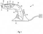
- Fig. 1 illustrated dental device 10has a housing 12 which is formed pistol-shaped substantially in a conventional manner.
- the housing 12receives at its front end a light source 14 in the form of an LED on the emitted light bundled a light guide is supplied.
- the housing 12also receives a switch 18, with which the dental device 10 is switched on for the light output.
- an accumulator 20is provided in a conventional manner, which preferably consists of a plurality of individual accumulator cells.
- a charging station 22is provided, which has a recess into which the handle 24 of the housing 12 fits.
- a plurality of double-layer capacitors 26, 28are arranged in the housing 12, wherein in Fig. 1 two double-layer capacitors 26, 28 are shown.
- the capacitors 26, 28are also arranged in the front region of the housing 12, but clearly behind the light source 14.
- the light source 14is mounted for cooling on a heat sink 30 which extends directly behind the light source 14. If necessary, the capacitors 26, 28 may be in heat conducting connections with the heat sink 30, so as to allow even a higher heat capacity without the capacitors 26, 28 would be affected too much by the heat release.
- the heat capacity of the double-layer capacitors 26, 28is at least twice, preferably four times, the heat capacity of the heat sink 30.
- the housing 12receives at its top, control elements.
- a control device 36is provided, which makes it possible to control and monitor all functions.
- the heat sink 30may have in known manner cooling fins, and can also be cooled by a likewise not shown blower in a suitable manner.
- Fig. 2a schematic circuit arrangement for the dental device 10 is shown.
- the circuit arrangementshows the light source 14, which is designed as a multiple arrangement of LED chips and is mounted on the heat sink 30, for example on a common heat sink 30 for a plurality of LED chips.
- the multiple arrangement of double-layer capacitors 26, 28is arranged, wherein here, for the sake of simplicity, four double-layer capacitors are shown.
- the double-layer capacitors 26, 28are connected to each other via a balancing circuit.
- Fig. 2shows only the light output, but not the charging of the double-layer capacitors 26, 28, which can be done both via the batteries 20 and via the charging station 22.
- a block diagramwhich shows the essential elements of the light curing device 10 according to the invention.
- the energy sourceis shown in the form of a block diagram and has an accumulator 20 and double-layer capacitors 26, 28. It is connected to a control device 36 which controls the discharge of the accumulator 20 on the one hand and the double-layer capacitors 26, 28 on the other hand as a central unit to supply the light source 14, which is also connected to the control device 36 with energy.
- the control device 36on a non-illustrated switching element, which ensures the switching in the desired manner.
- the polymerization cycleis initiated via a switch 18, which is likewise connected to the control device 36 and triggers a programmable timer which initially supplies charge from the double-layer capacitors 26, 28 of the light source 14 for a predetermined time.
- a switch 18which is likewise connected to the control device 36 and triggers a programmable timer which initially supplies charge from the double-layer capacitors 26, 28 of the light source 14 for a predetermined time.
- the double-layer capacitors 26, 28, of which in the embodiment according to FIG Fig. 2 four are shownare connected via a balancing circuit 29 with each other. This serves to ensure the uniformity of the charge on all four double-layer capacitors.
- the control device 36is also connected to an operating unit 34, which allows, for example, the setting of the polymerization time to be programmed or, for example, the selection of the calibration mode.
- an output unit 42is provided which can display the desired operating mode and any other parameters of the polymerization cycle on the one hand and of the dental device 10 on the other hand.
Landscapes
- Health & Medical Sciences (AREA)
- Oral & Maxillofacial Surgery (AREA)
- Dentistry (AREA)
- Epidemiology (AREA)
- Life Sciences & Earth Sciences (AREA)
- Animal Behavior & Ethology (AREA)
- General Health & Medical Sciences (AREA)
- Public Health (AREA)
- Veterinary Medicine (AREA)
- Physics & Mathematics (AREA)
- Optics & Photonics (AREA)
- Engineering & Computer Science (AREA)
- Water Supply & Treatment (AREA)
- Dental Tools And Instruments Or Auxiliary Dental Instruments (AREA)
Description
Translated fromGermanDie Erfindung betrifft ein handgeführtes Dentalgerät, gemäß dem Anspruch 1.The invention relates to a hand-held dental appliance, according to claim 1.
Handgeführte Dentalgeräte mit einer Lichtquelle und einer Energiequelle wie einem Akkumulator sind seit langem in der Dentaltechnik bekannt. Ein Beispiel hierfür ist das aus der
Kabellose Lichthärtgeräte sollen nach Möglichkeit nicht zu schwer sein.Wireless light curing devices should not be too heavy if possible.
Es ist das Bestreben der Zahnärzte und Zahntechniker, mit möglichst kurzen Polymerisationszyklen auszukommen. Hierzu stehen mittlerweile LED-Chips mit hoher Leistung zur Verfügung, die Lichtabgabezyklen von beispielsweise 20 oder 30 Sekunden ermöglichen.It is the endeavor of the dentists and dental technicians to get along with the shortest possible polymerization cycles. For this purpose, high-performance LED chips are now available which enable light emission cycles of, for example, 20 or 30 seconds.
Aus der
Aus der
Bei zu wenig Energie besteht die Problematik darin, dass die zur Verfügung stehende Ladungsmenge für einen Polymerisationszyklus nicht ausreicht, was dazu führen würde, dass nicht polymerisierte Monomere in den tieferen Schichten des Dentalrestaurationsteils verbleiben würden, die sehr kritisch gesehen werden, nachdem freie Radikale im Verdacht stehen, krebserregend zu wirken.With too little energy, the problem is that the amount of charge available is insufficient for one polymerization cycle, which would result in unpolymerized monomers remaining in the deeper layers of the dental restoration part, which are viewed very critically after free radicals are suspected stand to be carcinogenic.
Dies wird insbesondere dadurch kritischer, da die Leistungen von LED's heutzutage bis zu 10 Watt erreichen, so dass auch bei einem einzigen Polymerisationszyklus die Gefahr besteht, dass die gespeicherte Ladungsmenge nicht ausreicht, wenn der dortige Ultra-CapKondensator nicht ausreichend geladen ist.This is particularly critical because the performance of LEDs today reach up to 10 watts, so that even with a single polymerization cycle there is a risk that the stored charge amount is insufficient if the local Ultra Cap capacitor is not sufficiently charged.
Demgegenüber liegt der Erfindung die Aufgabe zugrunde, ein handgeführtes Dentalgerät zu schaffen, das auch bei der Verwendung von Hochleistungs-Lichtquellen die Energieversorgung mit Reserve zur Verfügung stellt.In contrast, the present invention seeks to provide a hand-held dental device that provides the energy supply with reserve even when using high-power light sources.
Diese Aufgabe wird erfindungsgemäß durch Anspruch 1 gelöst. Vorteilhafte Weiterbildungen ergeben sich aus den Unteransprüchen.This object is achieved by claim 1. Advantageous developments emerge from the subclaims.
Erfindungsgemäß ist es vorgesehen, einen Akkumulator, wie beispielsweise ein Lithium-Ionen-Akkumulator, mit mindestens einem zusätzlichen hochkapazitiven Doppelschicht-Kondensator zu kombinieren. Der von dem Akkumulator aufgeladene Doppelschicht-Kondensator hat eine sehr hohe Leistungsdichte von beispielsweise 5 W/g und wirkt als Haupt-Energielieferant für die Lichtquelle. Erfindungsgemäß wird die für die Polymerisation erforderliche Spannung durch den Akkumulator aufrechterhalten, beispielsweise, indem dann, wenn die Ladungsmenge, die auf dem Doppelschicht-Kondensator gespeichert ist, verbraucht wird, der Akkumulator als Spannungslieferant einspringt.According to the invention, it is provided to combine an accumulator, such as a lithium-ion accumulator, with at least one additional high-capacitance double-layer capacitor. The charged by the accumulator double-layer capacitor has a very high power density of, for example, 5 W / g and acts as the main source of energy for the light source. According to the invention, the voltage required for the polymerization is maintained by the accumulator, for example, by consuming the amount of charge stored on the double-layer capacitor when the accumulator enters as a voltage supplier.
Der Akkumulator hat bevorzugt eine recht hohe Energiedichte von beispielsweise 100 mWh/g, aber eine Leistungsdichte, die erheblich unter der Leistungsdichte des Doppelschicht-Kondensators liegt und beispielsweise 1 W/g beträgt.The accumulator preferably has a fairly high energy density of, for example, 100 mWh / g, but a power density which is considerably lower than the power density of the double-layer capacitor and, for example, 1 W / g.
In einer vorteilhaften Ausgestaltung wird die Energiequelle haptsächlich zur Aufladung des Kondensators verwendet. Um die bevorzugte und günstige Potentialverteilung sicherzustellen, kann man letztlich bei Bedarf auch eine Spannungserhöhungsschaltung einsetzen.In an advantageous embodiment, the energy source is used mainly for charging the capacitor. To ensure the preferred and cheap potential distribution, you can ultimately use a voltage booster circuit if necessary.
Es versteht sich, dass es anstelle dessen auch möglich ist, bei Aufladung des Akkumulators zugleich auch den Kondensator aufzuladen, und die Ladespannung beider lässt sich - auch im Verhältnis zueinander - in weiten Bereichen an die Erfordernisse anpassen. Beispielsweise kann der Doppelschicht-Kondensator (EDLC) eine Spannungsfestigkeit von 2,75 Volt haben und auf 2,6 Volt aufgeladen werden, während die Lithium-Ionen-Akkumulatorzellen je auf 1,25 Volt, also bei der Verwendung von 2 in Serie geschalteten Zellen, auf 2,5 Volt aufaeladen werden.It is understood that it is instead also possible to charge the capacitor at the same time when charging the battery, and the charging voltage of both can - even in relation to each other - in a wide range to adapt to the requirements. For example, the double layer capacitor (EDLC) may have a voltage rating of 2.75 volts and be charged to 2.6 volts while the lithium ion battery cells each depend on 1.25 volts, that is, using 2 series connected cells , to be charged to 2.5 volts.
Erfindungsgemäß besonders günstig ist es, wenn bei einer Mehrzahl von Kondensatoren eine Spannungs- und Stromvergleichmäßigung über ein sogenanntes balancing system erfolgt, das sicherstellt, dass alle Kondensatoren je die gleiche Ladung haben. Dies ist auch realisierbar, wenn beispielsweise 2 Kondensatoren parallel und 2 in Serie geschaltet sind, also eine Gesamtanordnung von 4 Kondensatoren vorliegt.According to the invention, it is particularly favorable if, in the case of a plurality of capacitors, voltage and current equalization take place via a so-called balancing system, which ensures that all capacitors each have the same charge. This can also be achieved if, for example, 2 capacitors are connected in parallel and 2 in series, ie an overall arrangement of 4 capacitors is present.
Die Doppelschicht-Kondensatore können eine beliebige geeignete Kapazität aufweisen. Typischerweise weist jeder Doppelschicht-Kondensator eine Kapazität von mindestens 1 F auf, wobei es aber auch möglich ist, eine Gesamtkapazität von beispielsweise 200 F aus 4 Doppelschicht-Kondensatore je 50 F zur Verfügung zu stellen.The bilayer capacitors may have any suitable capacitance. Typically, each double-layer capacitor has a capacitance of at least 1 F, but it is also possible to provide a total capacitance of, for example, 200 F of 4 double-layer capacitors per 50 F.
Besonders günstig ist es, dass der erfindungsgemäß als Primär-Energiespeicher verwendete Doppelschicht-Kondensator auch besonders geeignet ist, eine hohe Stromstärke abzugeben. So lässt sich beispielsweise im gepulsten Betrieb eine Zykluszeit von weniger als 10 Sekunden bei entsprechend hoher Strombeaufschlagung der LED-Chips realisieren, und eine Bestrahlungsstärke von beispielsweise 10 W/cm2 ist erfindungsgemäß erreichbar, ohne dass die Gefahr besteht, dass eine nicht-vollständige Polymerisation vorgenommen wird.It is particularly favorable that the double-layer capacitor used according to the invention as a primary energy store is also particularly suitable for delivering a high current intensity. For example, in pulsed operation, a cycle time of less than 10 can be achieved Seconds realize with correspondingly high current load of the LED chips, and an irradiance of, for example, 10 W / cm2 according to the invention can be achieved without the risk that a non-complete polymerization is made.
Erfindungsgemäß läßt sich in diesem Zusammenhang die Tatsache ausnutzen, dass die Leistungsdichten von Doppelschicht-Kondensatoren um mindestens eine Größenordnung, je nach Auslegung um mehr als zwei Größenordnungen höher als diejenigen von Lithium-lonen-Akkumulatoren sind.According to the invention can be exploited in this context, the fact that the power densities of double-layer capacitors by at least an order of magnitude, depending on the design by more than two orders of magnitude higher than those of lithium-ion batteries.
Erfindungsgemäß besonders günstig ist es, dass durch die Kombination der hohen Leistungsdichte im Bereich der Doppelschicht-Kondensatoren und die hohe Energiedichte im Bereich der Lithium-Ionen-Akkumulatoren sowohl ein Hochstrom-Impulsbetrieb möglich ist, ohne den Lithium-Ionen-Akkumulator zu stark zu belasten, als auch ein im Verhältnis zur gespeicherten Energie geringes Gewicht des handgeführten Dentalgeräts.According to the invention, it is particularly favorable that both high-current pulsed operation is possible by the combination of the high power density in the region of the double-layer capacitors and the high energy density in the region of the lithium-ion accumulators without excessively loading the lithium-ion accumulator , as well as in relation to the stored energy low weight of the hand-held dental device.
Da eine insgesamt verkürzte Behandlungsdauer erforderlich ist, ist auch die Wärmeableitung vereinfacht: Während bei einer Einschaltdauer von beispielsweise 30 Sekunden die Aufheizung über einen vergleichsweise längeren Zeitraum erfolgt, so dass sich ein gleichmäßig hohes Temperaturniveau einstellt, entsteht bei einer vergleichsweise kurzen Einschaltdauer von 10 Sekunden ein Temperaturpeak, der auch günstig über einen Wärmepuffer ableitbar ist. So kann beispielsweise das Substrat der LED-Chips als Kupferkörper mit einer vergleichsweise hohen Wärmeaufnahmekapazität ausgebildet sein. Als sekundärer Wärmepuffer lassen sich gegebenenfalls auch die Doppelschicht-Kondensatoren einsetzen, die - zwar auf einem geringeren Temperaturniveau - aber grundsätzlich auch eine Aufheizung von beispielsweise 20° C auf 50° C vertragen, die als Wärmepuffer-Kapazität einsetzbar ist.Since an overall shortened treatment time is required, the heat dissipation is simplified: while at a duty of 30 seconds, for example, the heating takes place over a relatively long period of time, so that sets a uniformly high temperature level, arises at a comparatively short duty cycle of 10 seconds Temperature peak, which is also derivable via a heat buffer. Thus, for example, the substrate of the LED chips can be designed as a copper body with a comparatively high heat absorption capacity. If necessary, the double-layer capacitors can also be used as the secondary heat buffer, although they tolerate heating of, for example, 20 ° C. to 50 ° C., although at a lower temperature level, which can be used as a heat buffer capacity.
Es ist günstig, wenn die Doppelschicht-Kondensatoren dem im vorderen Ende des Dentalgeräts insbesondere in der Nähe der Lichtquelle angeordnet sind.It is favorable if the double-layer capacitors are arranged in the front end of the dental device, in particular in the vicinity of the light source.
Erfindungsgemäß besonders günstig ist es, dass das Gerät mehrere, insbesondere vier, Doppelschicht-Kondensatoren aufweist.According to the invention, it is particularly favorable that the device has several, in particular four, double-layer capacitors.
Erfindungsgemäß besonders günstig ist es, dass das Gerät mehrere, insbesondere vier, Doppelschicht-Kondensatoren aufweist, die insbesondere der LED benachbart im vorderen Bereich des Dentalgeräts angeordnet sind.According to the invention, it is particularly favorable that the device has several, in particular four, double-layer capacitors, which are arranged in particular adjacent to the LED in the front region of the dental device.
Erfindungsgemäß besonders günstig ist es, dass das Gehäuse mehrere, insbesondere vier, Doppelschicht-Kondensatoren aufnimmt.According to the invention, it is particularly favorable for the housing to accommodate a plurality of, in particular four, double-layer capacitors.
Erfindungsgemäß besonders günstig ist es, dass die Doppelschicht-Kondensatoren eine Kapazität von mehr als Farad insbesondere etwa 4 Farad aufweisen.According to the invention, it is particularly favorable that the double-layer capacitors have a capacity of more than Farad, in particular approximately 4 Farads.
Erfindungsgemäß besonders günstig ist es, dass die Doppelschicht-Kondensatoren (26, 28) eine Energiedichte von mehr als 1 Wh/kg insbesondere etwa 3 Wh/kg, und eine Leistungsdichte von deutlich mehr als 1 W/g, insbesondere etwa 8 W/g aufweisen.According to the invention, it is particularly favorable that the double-layer capacitors (26, 28) have an energy density of more than 1 Wh / kg, in particular about 3 Wh / kg, and a power density of significantly more than 1 W / g, in particular about 8 W / g exhibit.
Erfindungsgemäß besonders günstig ist es, dass mindestens 2 der Doppelschicht-Kondensatoren parallel und/oder mindestens zwei der Doppelschicht-Kondensatoren seriell verbunden sind, die insbesondere über Vergleichmäßigungsschaltungen miteinander verbunden sind.It is particularly favorable in accordance with the invention for at least two of the double-layer capacitors to be connected in parallel in parallel and / or at least two of the double-layer capacitors, which are connected to one another in particular via equalization circuits.
Erfindungsgemäß besonders günstig ist es, dass der Doppelschicht-Kodensator von einem Lithium-Ionen-Kondensator gebildet ist.According to the invention, it is particularly favorable that the double-layer coder is formed by a lithium-ion capacitor.
Erfindungsgemäß besonders günstig ist es, dass eine externe Ladestation und/oder eine externe Energieversorgungseinrichtung vorgesehen ist.According to the invention, it is particularly advantageous that an external charging station and / or an external power supply device is provided.
Erfindungsgemäß besonders günstig ist es, dass das Dentalgerät wenigstens einen Betriebsmodus aufweist, in dem, wenn die Ladung auf dem mindestens einen Doppelschicht-Kondensator (26, 28) nicht mehr ausreicht, automatisch eine Umschaltung zur dem Akkumulator (20) erfolgt.According to the invention, it is particularly favorable that the dental device has at least one operating mode in which, when the charge on the at least one double-layer capacitor (26, 28) is no longer sufficient, switching to the accumulator (20) takes place automatically.
Erfindungsgemäß besonders günstig ist es, dass die Lichtquelle wenigstens zwei LED-Chips aufweist, die Licht mit zueinander gleichen oder unterschiedlichen Wellenlängen emittieren, insbesondere 7 LED-Chips, von denen 6 LED-Chips nicht mit einer Wellenlänge von 460 nm bis 500 nm, insbesondere 470 nm und ein LED-Chip nicht mit einer Wellenlänge von 380 bis 430 nm, insbesondere 410 nm emittieren.It is particularly favorable according to the invention that the light source has at least two LED chips which emit light with mutually identical or different wavelengths, in particular 7 LED chips, of which 6 LED chips do not have a wavelength of 460 nm to 500 nm, in particular 470 nm and a LED chip do not emit with a wavelength of 380 to 430 nm, in particular 410 nm.
Erfindungsgemäß besonders günstig ist es, dass in wenigstens einem der Belichtungsmodi das Licht mit einer Bestrahlungsstärke von 500 mW/cm2 bis 20.000 mW/cm2, insbesondere 8.000 mW/cm2 bis 12.000 mW/cm2 für einen Zeitraum von höchstens zwei Sekunden, insbesondere etwa 0,5 Sekunden bis 1,5 Sekunden, emittiert.According to the invention, it is particularly favorable that in at least one of the exposure modes the light with an irradiance of 500 mW / cm2 to 20,000 mW / cm2 , in particular 8,000 mW / cm2 to 12,000 mW / cm2 for a period of at most two seconds, in particular about 0.5 seconds to 1.5 seconds, emitted.
Erfindungsgemäß besonders günstig ist es, dass die Betriebsmodi des Dentalgerätes über eine mit der Steuereinheit in Verbindung stehende, akkustische oder optische Signale ausgebende Bedieneinheit auswählbar sind.According to the invention, it is particularly favorable that the operating modes of the dental appliance can be selected via an operating unit issuing acoustic or optical signals in communication with the control unit.
Erfindungsgemäß besonders günstig ist es, dass das Dentalgerät einen thermisch mit der LED verbundenen Kühlkörper für die Abführung der von der Lichtquelle erzeugten Wärme aufweist, der insbesondere am vorderen Ende des Gehäuses der Lichtquelle benachbart angeordnet ist.According to the invention, it is particularly favorable that the dental device has a heat sink thermally connected to the LED for dissipating the heat generated by the light source has, which is arranged adjacent to the light source in particular at the front end of the housing.
Erfindungsgemäß besonders günstig ist es, dass das Dentalgerät von einem Lichthärtgerät oder von einem Weichgewebelaser gebildet ist.According to the invention, it is particularly favorable that the dental device is formed by a light curing device or by a soft tissue laser.
Erfindungsgemäß besonders günstig ist es, dass das Lichthärtgerät einen insbesondere abnehmbaren Lichtleiter aufweist, der sich vor der Lichtquelle erstreckt.According to the invention, it is particularly favorable that the light curing device has an in particular removable optical fiber which extends in front of the light source.
Weitere Vorteile, Einzelheiten und Merkmale ergeben sich aus der nachfolgenden Beschreibung eines Ausführungsbeispiels der Erfindung anhand der Zeichnung.Further advantages, details and features will become apparent from the following description of an embodiment of the invention with reference to the drawing.
Es zeigen:
- Fig.1
- eine schematische Ansicht eines erfindungsgemäßen handgeführten Dentalgeräts in einer Ausführungsform; und
- Fig. 2
- eine schematische Ansicht einer Schaltung für das Dentalgerät in der Ausführung gemäß
Fig. 1 .
- Fig.1
- a schematic view of a hand-held dental device according to the invention in one embodiment; and
- Fig. 2
- a schematic view of a circuit for the dental device in the embodiment according to
Fig. 1 ,
Das in
Das Gehäuse 12 nimmt ferner einen Schalter 18 auf, mit welchem das Dentalgerät 10 für die Lichtabgabe einschaltbar ist. Im Handgriff 24 des Gehäuses 12 ist in an sich bekannter Weise ein Akkumulator 20 vorgesehen, der bevorzugt aus einer Mehrzahl von einzelnen Akkumulatorzellen besteht. Für das Wiederaufladen des Akkumulators 20 ist eine Ladestation 22 vorgesehen, die eine Ausnehmung aufweist, in die der Handgriff 24 des Gehäuses 12 hineinpasst. Beim Einstellen des Handgriffs 24 in die Ausnehmung der Ladestation 22 werden zugleich elektrische Kontakte hergestellt, die die Spannungsversorgung des Dentalgeräts 10, das handgeführt ausgebildet ist, sicherstellen.The
Erfindungsgemäß sind eine Mehrzahl von Doppelschicht-Kondensatoren 26, 28 in dem Gehäuse 12 angeordnet, wobei in
In dem dargestellten Ausführungsbeispiel beträgt die Wärmekapazität der Doppelschicht-Kondensatoren 26, 28 mindestens das Doppelte, bevorzugt das vierfache der Wärmekapazität des Kühlkörpers 30.In the illustrated embodiment, the heat capacity of the double-
In an sich bekannter Weise nimmt das Gehäuse 12 an seiner Oberseite, Steuerungselemente auf. Hierzu gehört eine Ausgabe beispielsweise in Form eines Lautsprechers 32 und eine Bedieneinheit 34. Diese kann die eine LCD-Ausgabeeinheit oder einen Touch Screen für die Einstellung und das Auswählen eines Polymerisationszykluses umfassen.In a conventional manner, the
Zur Steuerung des Dentalgeräts 10 ist eine Steuereinrichtung 36 vorgesehen, die es ermöglicht, sämtliche Funktionen zu steuern und zu überwachen.To control the
Auch wenn dies in
In
Bevorzugt in Nähe hierzu ist die Mehrfachanordnung von Doppelschicht-Kondensatoren 26, 28 angeordnet, wobei hier, der Einfachheit halber, vier Doppelschicht-Kondensatoren dargestellt sind. Tatsächlich sind die Doppelschicht-Kondensatoren 26, 28 über eine Vergleichmäßigungsschaltung miteinander verbunden.Preferably in the vicinity of this, the multiple arrangement of double-
Die Darstellung gemäß
Gemäß der Darstellung in
Die Auslösung des Polymerisationszyklusses erfolgt über einen Schalter 18, der ebenfalls mit der Steuereinrichtung 36 verbunden ist und einen programmierbaren Timer auslöst, der für eine vorgegebene Zeit Ladung zunächst aus den Doppelschicht-Kondensatoren 26, 28 der Lichtquelle 14 zuführt. Wenn die Ladung auf den Doppelschicht-Kondensatoren 26, 28 nicht mehr ausreicht, also wenn die Spannung an dieser Stelle zu gering geworden ist, erfolgt in erfindungsgemäß günstiger Ausgestaltung automatisch eine Umschaltung, so dass der Akkumulator 20 verzögerungsfrei den Polymerisationszyklus fortsetzt.The polymerization cycle is initiated via a
Die Doppelschicht-Kondensatoren 26, 28, von denen in der Ausführungsform gemäß
Die Steuereinrichtung 36 ist ferner mit einer Bedieneinheit 34 verbunden, die beispielsweise die Einstellung der zu programmierenden Polymerisationszeit oder beispielsweise die Anwahl des Kalibriermodus ermöglicht.The
Ferner ist eine Ausgabeeinheit 42 vorgesehen, die den gewünschten Betriebsmodus und beliebige andere Parameter des Polymerisationszyklusses einerseits und des Dentalgeräts 10 andererseits darstellen kann.Furthermore, an
Claims (13)
- A hand-held dental device, comprising a housing (12) in which a light source (14), in particular at least one LED, is connected to an energy source and a control device (36), wherein the energy source is composed of at least one accumulator (20), in particular a lithium ion accumulator (20), and at least one energy storage in the form of at least one double layer capacitor (26, 28).
- The dental device as claimed in claim 1,characterized in that the device comprises several, in particular four, double layer capacitors (26, 28).
- The dental device as claimed in one of the preceding claims,characterized in that the double layer capacitors (26,28) have a capacity of more than 1 Farad, in particular approximately 4 Farad.
- The dental device as claimed in one of the preceding claims,characterized in that at least 2 of the double layer capacitors (26, 28) are connected in parallel and/or at least 2 of the double layer capacitors (26, 28) are connected in series, which in particular are connected to each other via balancing circuits.
- The dental device as claimed in one of the preceding claims,characterized in that the double layer capacitor is formed by a lithium ion capacitor.
- The dental device as claimed in one of the preceding claims,characterized in that an external charging unit (22) and/or an external energy supply unit is provided
- The dental device as claimed in one of the preceding claims,characterized in that the dental device (10) comprises at least one operating mode in which, when the charge on the at least one double layer capacitor (26, 28) is not sufficient any longer, switching to the accumulator (20) takes place automatically.
- The dental device as claimed in one of the preceding claims,characterized in that the light source (14) comprises at least two LED chips which emit light at wavelengths which are equal to or different from one another, in particular 7 LED chips, of which 6 LED chips do not emit at a wavelength of 460 nm to 500 nm, in particular 470 nm, and one LED chip does not emit at a wavelength of 380 to 430 nm, in particular 410 nm.
- The dental device as claimed in one of the preceding claims,characterized in that in at least one of the exposure modes light is emitted at an irradiance of 500 mW/cm2 to 20,000 mW/cm2, in particular 8,000 mW/cm2 to 12,000 mW/cm2 for a period of two seconds at most, in particular approximately 0.5 seconds to 1.5 seconds.
- The dental device as claimed in one of the preceding claims,characterized in that the operating modes of the dental device (10) are selectable via an operating unit (34) which is connected to the control device (36) and which outputs acoustical or optical signals.
- The dental device as claimed in one of the preceding claims,characterized in that the dental device (10) comprises a heat sink (30) which is thermally connected to the LED for dissipating the heat which is produced by the light source (14), which heat sink is located in particular at the front end of the housing (12) adjacent to the light source (14).
- The dental device as claimed in one of the preceding claims,characterized in that the dental device (10) is formed by a light curing apparatus or by a soft tissue laser.
- The dental device as claimed in one of the preceding claims,characterized in that the light curing apparatus comprises a particularly detachable light guide which extends in front of the light source (14).
Priority Applications (7)
| Application Number | Priority Date | Filing Date | Title |
|---|---|---|---|
| EP10196001.1AEP2465466B1 (en) | 2010-12-20 | 2010-12-20 | Handheld dental device |
| ES10196001.1TES2605175T3 (en) | 2010-12-20 | 2010-12-20 | Hand-guided dental appliance |
| ES11193642.3TES2652496T3 (en) | 2010-12-20 | 2011-12-15 | Handpiece with light source |
| EP11193642.3AEP2465467B1 (en) | 2010-12-20 | 2011-12-15 | Handpiece with light source |
| US13/328,463US9179990B2 (en) | 2010-12-20 | 2011-12-16 | Hand-held dental device |
| JP2011277752AJP5735409B2 (en) | 2010-12-20 | 2011-12-19 | Hand-held dental device and its application |
| US14/877,336US20160022396A1 (en) | 2010-12-20 | 2015-10-07 | Hand-held dental device |
Applications Claiming Priority (1)
| Application Number | Priority Date | Filing Date | Title |
|---|---|---|---|
| EP10196001.1AEP2465466B1 (en) | 2010-12-20 | 2010-12-20 | Handheld dental device |
Publications (2)
| Publication Number | Publication Date |
|---|---|
| EP2465466A1 EP2465466A1 (en) | 2012-06-20 |
| EP2465466B1true EP2465466B1 (en) | 2016-10-12 |
Family
ID=43828168
Family Applications (2)
| Application Number | Title | Priority Date | Filing Date |
|---|---|---|---|
| EP10196001.1AActiveEP2465466B1 (en) | 2010-12-20 | 2010-12-20 | Handheld dental device |
| EP11193642.3AActiveEP2465467B1 (en) | 2010-12-20 | 2011-12-15 | Handpiece with light source |
Family Applications After (1)
| Application Number | Title | Priority Date | Filing Date |
|---|---|---|---|
| EP11193642.3AActiveEP2465467B1 (en) | 2010-12-20 | 2011-12-15 | Handpiece with light source |
Country Status (4)
| Country | Link |
|---|---|
| US (2) | US9179990B2 (en) |
| EP (2) | EP2465466B1 (en) |
| JP (1) | JP5735409B2 (en) |
| ES (2) | ES2605175T3 (en) |
Cited By (1)
| Publication number | Priority date | Publication date | Assignee | Title |
|---|---|---|---|---|
| US10368969B2 (en)* | 2017-04-21 | 2019-08-06 | Xlr8 Holdings, Llc | Hand-held device utilizing an activation mechanism which spans the circumference of said device |
Families Citing this family (8)
| Publication number | Priority date | Publication date | Assignee | Title |
|---|---|---|---|---|
| US11490999B2 (en)* | 2013-07-23 | 2022-11-08 | Ivoclar Vivadent Ag | Light curing device for dental restoration materials and method of curing dental restoration materials |
| JP2017533058A (en) | 2014-09-17 | 2017-11-09 | ギャリソン デンタル ソリューションズ,リミティド ライアビリティ カンパニー | Dental curing light |
| EP3106124B1 (en)* | 2015-06-17 | 2019-09-04 | Ivoclar Vivadent AG | Light hardening device |
| US20170215698A1 (en)* | 2016-01-28 | 2017-08-03 | Dental Wings Inc. | System and method for providing user feedback indications during intra-oral scanning process |
| EP3257470B1 (en)* | 2016-06-17 | 2019-07-24 | Ivoclar Vivadent AG | Light curing device with control circuit |
| USD810293S1 (en) | 2017-01-20 | 2018-02-13 | Garrison Dental Solutions, Llc | Dental instrument |
| US11439839B2 (en)* | 2017-08-09 | 2022-09-13 | Acuity Innovation And Design, Llc | Hand-held treatment device using LED light sources with interchangeable emitters |
| CN112515802B (en)* | 2019-09-18 | 2022-08-05 | 广州星际悦动股份有限公司 | Electric tooth brush |
Family Cites Families (27)
| Publication number | Priority date | Publication date | Assignee | Title |
|---|---|---|---|---|
| DE4211230C2 (en) | 1992-04-03 | 1997-06-26 | Ivoclar Ag | Rechargeable light curing device |
| US5420768A (en)* | 1993-09-13 | 1995-05-30 | Kennedy; John | Portable led photocuring device |
| JP2001517875A (en)* | 1997-09-25 | 2001-10-09 | ユニバーシティ オブ ブリストル | Light irradiation device |
| IT1296089B1 (en)* | 1997-11-10 | 1999-06-09 | Mectron Di Bianchetti Fernando | DENTAL HANDPIECE WITH LIGHT SOURCE FOR DIAGNOSTIC PURPOSE |
| US6200134B1 (en)* | 1998-01-20 | 2001-03-13 | Kerr Corporation | Apparatus and method for curing materials with radiation |
| KR20010099905A (en)* | 1998-12-23 | 2001-11-09 | 리차드 에이. 에크하드트 | Method and apparatus for sterilizing small objects |
| US6140776A (en)* | 1999-04-06 | 2000-10-31 | Rachwal; Erwin J. | Flashlight |
| US6386866B1 (en)* | 1999-11-12 | 2002-05-14 | Dentsply Research & Development Corp. | Ultrasonic dental insert and handpiece having a light source |
| JP2002200100A (en) | 2000-12-27 | 2002-07-16 | Dental Systems Kk | Projector |
| JP4046479B2 (en) | 2001-02-09 | 2008-02-13 | 株式会社リコー | Lighting device for photography |
| US6866506B2 (en) | 2001-05-23 | 2005-03-15 | Ivoclar Vivadent Ag | Light hardening apparatus particularly for a dental practice |
| DE10125340B4 (en)* | 2001-05-23 | 2004-08-05 | Ivoclar Vivadent Ag | Dental light device |
| US6955539B2 (en)* | 2001-07-12 | 2005-10-18 | Water Pik, Inc. | Characterization of motion of dual motor oral hygiene device |
| AU2003200381A1 (en)* | 2002-02-14 | 2003-09-04 | Gc Corporation | Light irradiation apparatus for dental photo polymerization composite resin |
| JP4130371B2 (en) | 2003-01-30 | 2008-08-06 | 株式会社松風 | LED light irradiator for oral cavity |
| US7250045B2 (en)* | 2003-02-25 | 2007-07-31 | Spectragenics, Inc. | Self-contained, eye-safe hair-regrowth-inhibition apparatus and method |
| DE10320141B4 (en)* | 2003-05-06 | 2010-11-25 | Ivoclar Vivadent Ag | light polymerization |
| JP3100119U (en) | 2003-08-28 | 2004-04-30 | 朱武隆 | Electric screwdriver |
| ES2379174T3 (en) | 2003-11-04 | 2012-04-23 | Glaxo Group Limited | Electric toothbrush |
| DE102004033699A1 (en) | 2004-07-13 | 2006-02-16 | Polydentia Sa | Cable less light hardening system for dental fillings is based upon an LED supplied by a rechargeable capacitor |
| US7210814B2 (en)* | 2005-04-29 | 2007-05-01 | Ultradent Products, Inc. | Dental curing light with specially arranged LEDs |
| JP2008061469A (en) | 2006-09-04 | 2008-03-13 | Toshiba Mitsubishi-Electric Industrial System Corp | Energy storage device using electric double-layer capacitor |
| CZ2008169A3 (en)* | 2008-03-14 | 2009-09-23 | Ydun, S. R. O. | Lead-free starting accumulator battery intended particularly for internal combustion engines and motor vehicles |
| JP5322514B2 (en) | 2008-06-30 | 2013-10-23 | 大崎データテック株式会社 | Periodic power supply device for thermal print head |
| WO2010029519A2 (en)* | 2008-09-15 | 2010-03-18 | Trd Instrum Ltd. | A curing light device |
| US9066777B2 (en)* | 2009-04-02 | 2015-06-30 | Kerr Corporation | Curing light device |
| US8496475B2 (en)* | 2009-12-11 | 2013-07-30 | Hu-Friedy Mfg. Co., LLC. | Integrated, lighted ultrasonic inserts |
- 2010
- 2010-12-20EPEP10196001.1Apatent/EP2465466B1/enactiveActive
- 2010-12-20ESES10196001.1Tpatent/ES2605175T3/enactiveActive
- 2011
- 2011-12-15ESES11193642.3Tpatent/ES2652496T3/enactiveActive
- 2011-12-15EPEP11193642.3Apatent/EP2465467B1/enactiveActive
- 2011-12-16USUS13/328,463patent/US9179990B2/enactiveActive
- 2011-12-19JPJP2011277752Apatent/JP5735409B2/enactiveActive
- 2015
- 2015-10-07USUS14/877,336patent/US20160022396A1/ennot_activeAbandoned
Non-Patent Citations (1)
| Title |
|---|
| None* |
Cited By (1)
| Publication number | Priority date | Publication date | Assignee | Title |
|---|---|---|---|---|
| US10368969B2 (en)* | 2017-04-21 | 2019-08-06 | Xlr8 Holdings, Llc | Hand-held device utilizing an activation mechanism which spans the circumference of said device |
Also Published As
| Publication number | Publication date |
|---|---|
| JP2012130691A (en) | 2012-07-12 |
| JP5735409B2 (en) | 2015-06-17 |
| EP2465467B1 (en) | 2017-10-25 |
| ES2605175T3 (en) | 2017-03-13 |
| US20120156637A1 (en) | 2012-06-21 |
| EP2465466A1 (en) | 2012-06-20 |
| US20160022396A1 (en) | 2016-01-28 |
| ES2652496T3 (en) | 2018-02-02 |
| US9179990B2 (en) | 2015-11-10 |
| EP2465467A1 (en) | 2012-06-20 |
Similar Documents
| Publication | Publication Date | Title |
|---|---|---|
| EP2465466B1 (en) | Handheld dental device | |
| EP2165402B1 (en) | Device, in particular charging device for charging an accumulator | |
| EP2962380B1 (en) | Circuit arrangement for inline voltage supply, use of such a circuit arrangement and device having such a circuit arrangement | |
| DE102006061270B4 (en) | Battery pack and battery module | |
| DE102011076981B4 (en) | Battery system, motor vehicle with this battery system and method for producing operational readiness in a motor vehicle with this battery system | |
| DE212017000113U1 (en) | Adapter, portable electrical energy system and electrical energy system | |
| DE102012110030A1 (en) | Energy storage device and method for operating the same | |
| DE102009027685A1 (en) | Solar-powered battery charger | |
| DE112011100550B4 (en) | cell capacity adjuster | |
| DE102008040524B4 (en) | Power tool with a device for pulse width modulated current control | |
| DE102013204888A1 (en) | Method for balancing different states of charge of batteries | |
| EP2254218B1 (en) | Device and method for charging batteries | |
| DE102007043093A1 (en) | Color temperature control of flash units | |
| DE102012209995A1 (en) | Switching device for a battery and corresponding switching method | |
| DE102014108601A1 (en) | Method for connecting a plurality of battery units to a two-pole input of a bidirectional battery converter and bidirectional battery converter and photovoltaic inverter | |
| DE102009028945B3 (en) | Manual welding device | |
| DE102010019088A1 (en) | Method for optimizing utilization of network-independent supply of e.g. music player in passenger car, involves subjecting battery units to charging process while reaching discharge state of battery units by switching to other battery units | |
| EP1798846A1 (en) | Electrical apparatus with battery compartement and power supply | |
| DE3315923C2 (en) | Charger for batteries and the like. | |
| DE102012020544A1 (en) | Device for charging two serially connected battery cells of energy storage i.e. battery, has charging devices connected with battery cells of energy storage and connected with power supply independent of state of charge of cells | |
| DE102007031563A1 (en) | Battery with a customizable charge shutdown voltage | |
| DE10333421A1 (en) | Electrically operated portable apparatus especially pocket torch and circuit can switch between battery and accumulator operation to extend accumulator life | |
| DE19931905C2 (en) | battery battery | |
| DE102017002621A1 (en) | Device for energy storage and / or energy delivery | |
| DE102007056976A1 (en) | Battery e.g. lithium-ion battery, storage charge adjusting method for load, involves utilizing adjusting switch for adjusting storage charge of battery, discharging battery upon initial value and charging battery upon storage charge |
Legal Events
| Date | Code | Title | Description |
|---|---|---|---|
| PUAI | Public reference made under article 153(3) epc to a published international application that has entered the european phase | Free format text:ORIGINAL CODE: 0009012 | |
| AK | Designated contracting states | Kind code of ref document:A1 Designated state(s):AL AT BE BG CH CY CZ DE DK EE ES FI FR GB GR HR HU IE IS IT LI LT LU LV MC MK MT NL NO PL PT RO RS SE SI SK SM TR | |
| AX | Request for extension of the european patent | Extension state:BA ME | |
| 17P | Request for examination filed | Effective date:20120626 | |
| 17Q | First examination report despatched | Effective date:20150527 | |
| GRAJ | Information related to disapproval of communication of intention to grant by the applicant or resumption of examination proceedings by the epo deleted | Free format text:ORIGINAL CODE: EPIDOSDIGR1 | |
| GRAP | Despatch of communication of intention to grant a patent | Free format text:ORIGINAL CODE: EPIDOSNIGR1 | |
| GRAP | Despatch of communication of intention to grant a patent | Free format text:ORIGINAL CODE: EPIDOSNIGR1 | |
| INTG | Intention to grant announced | Effective date:20160425 | |
| GRAJ | Information related to disapproval of communication of intention to grant by the applicant or resumption of examination proceedings by the epo deleted | Free format text:ORIGINAL CODE: EPIDOSDIGR1 | |
| GRAS | Grant fee paid | Free format text:ORIGINAL CODE: EPIDOSNIGR3 | |
| GRAP | Despatch of communication of intention to grant a patent | Free format text:ORIGINAL CODE: EPIDOSNIGR1 | |
| INTC | Intention to grant announced (deleted) | ||
| INTG | Intention to grant announced | Effective date:20160810 | |
| GRAA | (expected) grant | Free format text:ORIGINAL CODE: 0009210 | |
| AK | Designated contracting states | Kind code of ref document:B1 Designated state(s):AL AT BE BG CH CY CZ DE DK EE ES FI FR GB GR HR HU IE IS IT LI LT LU LV MC MK MT NL NO PL PT RO RS SE SI SK SM TR | |
| REG | Reference to a national code | Ref country code:GB Ref legal event code:FG4D Free format text:NOT ENGLISH | |
| REG | Reference to a national code | Ref country code:CH Ref legal event code:EP Ref country code:CH Ref legal event code:NV Representative=s name:KELLER AND PARTNER PATENTANWAELTE AG, CH | |
| REG | Reference to a national code | Ref country code:AT Ref legal event code:REF Ref document number:835754 Country of ref document:AT Kind code of ref document:T Effective date:20161015 | |
| REG | Reference to a national code | Ref country code:IE Ref legal event code:FG4D Free format text:LANGUAGE OF EP DOCUMENT: GERMAN | |
| REG | Reference to a national code | Ref country code:FR Ref legal event code:PLFP Year of fee payment:7 | |
| REG | Reference to a national code | Ref country code:DE Ref legal event code:R096 Ref document number:502010012546 Country of ref document:DE | |
| REG | Reference to a national code | Ref country code:SE Ref legal event code:TRGR | |
| REG | Reference to a national code | Ref country code:LT Ref legal event code:MG4D | |
| REG | Reference to a national code | Ref country code:NL Ref legal event code:MP Effective date:20161012 | |
| PG25 | Lapsed in a contracting state [announced via postgrant information from national office to epo] | Ref country code:LV Free format text:LAPSE BECAUSE OF FAILURE TO SUBMIT A TRANSLATION OF THE DESCRIPTION OR TO PAY THE FEE WITHIN THE PRESCRIBED TIME-LIMIT Effective date:20161012 | |
| REG | Reference to a national code | Ref country code:ES Ref legal event code:FG2A Ref document number:2605175 Country of ref document:ES Kind code of ref document:T3 Effective date:20170313 | |
| PG25 | Lapsed in a contracting state [announced via postgrant information from national office to epo] | Ref country code:NO Free format text:LAPSE BECAUSE OF FAILURE TO SUBMIT A TRANSLATION OF THE DESCRIPTION OR TO PAY THE FEE WITHIN THE PRESCRIBED TIME-LIMIT Effective date:20170112 Ref country code:LT Free format text:LAPSE BECAUSE OF FAILURE TO SUBMIT A TRANSLATION OF THE DESCRIPTION OR TO PAY THE FEE WITHIN THE PRESCRIBED TIME-LIMIT Effective date:20161012 Ref country code:GR Free format text:LAPSE BECAUSE OF FAILURE TO SUBMIT A TRANSLATION OF THE DESCRIPTION OR TO PAY THE FEE WITHIN THE PRESCRIBED TIME-LIMIT Effective date:20170113 | |
| PG25 | Lapsed in a contracting state [announced via postgrant information from national office to epo] | Ref country code:BE Free format text:LAPSE BECAUSE OF NON-PAYMENT OF DUE FEES Effective date:20161231 Ref country code:NL Free format text:LAPSE BECAUSE OF FAILURE TO SUBMIT A TRANSLATION OF THE DESCRIPTION OR TO PAY THE FEE WITHIN THE PRESCRIBED TIME-LIMIT Effective date:20161012 Ref country code:IS Free format text:LAPSE BECAUSE OF FAILURE TO SUBMIT A TRANSLATION OF THE DESCRIPTION OR TO PAY THE FEE WITHIN THE PRESCRIBED TIME-LIMIT Effective date:20170212 Ref country code:RS Free format text:LAPSE BECAUSE OF FAILURE TO SUBMIT A TRANSLATION OF THE DESCRIPTION OR TO PAY THE FEE WITHIN THE PRESCRIBED TIME-LIMIT Effective date:20161012 Ref country code:PL Free format text:LAPSE BECAUSE OF FAILURE TO SUBMIT A TRANSLATION OF THE DESCRIPTION OR TO PAY THE FEE WITHIN THE PRESCRIBED TIME-LIMIT Effective date:20161012 Ref country code:PT Free format text:LAPSE BECAUSE OF FAILURE TO SUBMIT A TRANSLATION OF THE DESCRIPTION OR TO PAY THE FEE WITHIN THE PRESCRIBED TIME-LIMIT Effective date:20170213 Ref country code:HR Free format text:LAPSE BECAUSE OF FAILURE TO SUBMIT A TRANSLATION OF THE DESCRIPTION OR TO PAY THE FEE WITHIN THE PRESCRIBED TIME-LIMIT Effective date:20161012 Ref country code:FI Free format text:LAPSE BECAUSE OF FAILURE TO SUBMIT A TRANSLATION OF THE DESCRIPTION OR TO PAY THE FEE WITHIN THE PRESCRIBED TIME-LIMIT Effective date:20161012 | |
| REG | Reference to a national code | Ref country code:DE Ref legal event code:R097 Ref document number:502010012546 Country of ref document:DE | |
| PG25 | Lapsed in a contracting state [announced via postgrant information from national office to epo] | Ref country code:SK Free format text:LAPSE BECAUSE OF FAILURE TO SUBMIT A TRANSLATION OF THE DESCRIPTION OR TO PAY THE FEE WITHIN THE PRESCRIBED TIME-LIMIT Effective date:20161012 Ref country code:RO Free format text:LAPSE BECAUSE OF FAILURE TO SUBMIT A TRANSLATION OF THE DESCRIPTION OR TO PAY THE FEE WITHIN THE PRESCRIBED TIME-LIMIT Effective date:20161012 Ref country code:CZ Free format text:LAPSE BECAUSE OF FAILURE TO SUBMIT A TRANSLATION OF THE DESCRIPTION OR TO PAY THE FEE WITHIN THE PRESCRIBED TIME-LIMIT Effective date:20161012 Ref country code:DK Free format text:LAPSE BECAUSE OF FAILURE TO SUBMIT A TRANSLATION OF THE DESCRIPTION OR TO PAY THE FEE WITHIN THE PRESCRIBED TIME-LIMIT Effective date:20161012 Ref country code:EE Free format text:LAPSE BECAUSE OF FAILURE TO SUBMIT A TRANSLATION OF THE DESCRIPTION OR TO PAY THE FEE WITHIN THE PRESCRIBED TIME-LIMIT Effective date:20161012 | |
| PLBE | No opposition filed within time limit | Free format text:ORIGINAL CODE: 0009261 | |
| STAA | Information on the status of an ep patent application or granted ep patent | Free format text:STATUS: NO OPPOSITION FILED WITHIN TIME LIMIT | |
| PG25 | Lapsed in a contracting state [announced via postgrant information from national office to epo] | Ref country code:BG Free format text:LAPSE BECAUSE OF FAILURE TO SUBMIT A TRANSLATION OF THE DESCRIPTION OR TO PAY THE FEE WITHIN THE PRESCRIBED TIME-LIMIT Effective date:20170112 Ref country code:SM Free format text:LAPSE BECAUSE OF FAILURE TO SUBMIT A TRANSLATION OF THE DESCRIPTION OR TO PAY THE FEE WITHIN THE PRESCRIBED TIME-LIMIT Effective date:20161012 | |
| 26N | No opposition filed | Effective date:20170713 | |
| PG25 | Lapsed in a contracting state [announced via postgrant information from national office to epo] | Ref country code:MC Free format text:LAPSE BECAUSE OF FAILURE TO SUBMIT A TRANSLATION OF THE DESCRIPTION OR TO PAY THE FEE WITHIN THE PRESCRIBED TIME-LIMIT Effective date:20161012 | |
| REG | Reference to a national code | Ref country code:IE Ref legal event code:MM4A | |
| PG25 | Lapsed in a contracting state [announced via postgrant information from national office to epo] | Ref country code:LU Free format text:LAPSE BECAUSE OF NON-PAYMENT OF DUE FEES Effective date:20161220 | |
| REG | Reference to a national code | Ref country code:FR Ref legal event code:PLFP Year of fee payment:8 | |
| PG25 | Lapsed in a contracting state [announced via postgrant information from national office to epo] | Ref country code:SI Free format text:LAPSE BECAUSE OF FAILURE TO SUBMIT A TRANSLATION OF THE DESCRIPTION OR TO PAY THE FEE WITHIN THE PRESCRIBED TIME-LIMIT Effective date:20161012 Ref country code:IE Free format text:LAPSE BECAUSE OF NON-PAYMENT OF DUE FEES Effective date:20161220 | |
| REG | Reference to a national code | Ref country code:BE Ref legal event code:MM Effective date:20161231 | |
| PG25 | Lapsed in a contracting state [announced via postgrant information from national office to epo] | Ref country code:CY Free format text:LAPSE BECAUSE OF FAILURE TO SUBMIT A TRANSLATION OF THE DESCRIPTION OR TO PAY THE FEE WITHIN THE PRESCRIBED TIME-LIMIT Effective date:20161012 Ref country code:HU Free format text:LAPSE BECAUSE OF FAILURE TO SUBMIT A TRANSLATION OF THE DESCRIPTION OR TO PAY THE FEE WITHIN THE PRESCRIBED TIME-LIMIT; INVALID AB INITIO Effective date:20101220 | |
| PG25 | Lapsed in a contracting state [announced via postgrant information from national office to epo] | Ref country code:MK Free format text:LAPSE BECAUSE OF FAILURE TO SUBMIT A TRANSLATION OF THE DESCRIPTION OR TO PAY THE FEE WITHIN THE PRESCRIBED TIME-LIMIT Effective date:20161012 Ref country code:TR Free format text:LAPSE BECAUSE OF FAILURE TO SUBMIT A TRANSLATION OF THE DESCRIPTION OR TO PAY THE FEE WITHIN THE PRESCRIBED TIME-LIMIT Effective date:20161012 | |
| PG25 | Lapsed in a contracting state [announced via postgrant information from national office to epo] | Ref country code:MT Free format text:LAPSE BECAUSE OF FAILURE TO SUBMIT A TRANSLATION OF THE DESCRIPTION OR TO PAY THE FEE WITHIN THE PRESCRIBED TIME-LIMIT Effective date:20161012 | |
| REG | Reference to a national code | Ref country code:FR Ref legal event code:PLFP Year of fee payment:9 | |
| PG25 | Lapsed in a contracting state [announced via postgrant information from national office to epo] | Ref country code:AL Free format text:LAPSE BECAUSE OF FAILURE TO SUBMIT A TRANSLATION OF THE DESCRIPTION OR TO PAY THE FEE WITHIN THE PRESCRIBED TIME-LIMIT Effective date:20161012 | |
| REG | Reference to a national code | Ref country code:CH Ref legal event code:PFA Owner name:IVOCLAR VIVADENT AG, LI Free format text:FORMER OWNER: IVOCLAR VIVADENT AG, LI | |
| P01 | Opt-out of the competence of the unified patent court (upc) registered | Effective date:20230607 | |
| PGFP | Annual fee paid to national office [announced via postgrant information from national office to epo] | Ref country code:GB Payment date:20231107 Year of fee payment:14 | |
| PGFP | Annual fee paid to national office [announced via postgrant information from national office to epo] | Ref country code:SE Payment date:20231107 Year of fee payment:14 Ref country code:IT Payment date:20231218 Year of fee payment:14 Ref country code:FR Payment date:20231107 Year of fee payment:14 Ref country code:DE Payment date:20231107 Year of fee payment:14 Ref country code:AT Payment date:20231114 Year of fee payment:14 | |
| PGFP | Annual fee paid to national office [announced via postgrant information from national office to epo] | Ref country code:ES Payment date:20240105 Year of fee payment:14 | |
| PGFP | Annual fee paid to national office [announced via postgrant information from national office to epo] | Ref country code:CH Payment date:20240101 Year of fee payment:14 | |
| REG | Reference to a national code | Ref country code:DE Ref legal event code:R119 Ref document number:502010012546 Country of ref document:DE | |
| REG | Reference to a national code | Ref country code:SE Ref legal event code:EUG | |
| REG | Reference to a national code | Ref country code:CH Ref legal event code:PL | |
| REG | Reference to a national code | Ref country code:AT Ref legal event code:MM01 Ref document number:835754 Country of ref document:AT Kind code of ref document:T Effective date:20241220 | |
| GBPC | Gb: european patent ceased through non-payment of renewal fee | Effective date:20241220 |