EP2465028B1 - Card dispensing apparatuses and associated methods of operation - Google Patents
Card dispensing apparatuses and associated methods of operationDownload PDFInfo
- Publication number
- EP2465028B1 EP2465028B1EP10808465.8AEP10808465AEP2465028B1EP 2465028 B1EP2465028 B1EP 2465028B1EP 10808465 AEP10808465 AEP 10808465AEP 2465028 B1EP2465028 B1EP 2465028B1
- Authority
- EP
- European Patent Office
- Prior art keywords
- card
- carriage
- hoppers
- hopper
- cards
- Prior art date
- Legal status (The legal status is an assumption and is not a legal conclusion. Google has not performed a legal analysis and makes no representation as to the accuracy of the status listed.)
- Not-in-force
Links
Images


Classifications
- G—PHYSICS
- G06—COMPUTING OR CALCULATING; COUNTING
- G06Q—INFORMATION AND COMMUNICATION TECHNOLOGY [ICT] SPECIALLY ADAPTED FOR ADMINISTRATIVE, COMMERCIAL, FINANCIAL, MANAGERIAL OR SUPERVISORY PURPOSES; SYSTEMS OR METHODS SPECIALLY ADAPTED FOR ADMINISTRATIVE, COMMERCIAL, FINANCIAL, MANAGERIAL OR SUPERVISORY PURPOSES, NOT OTHERWISE PROVIDED FOR
- G06Q20/00—Payment architectures, schemes or protocols
- G06Q20/30—Payment architectures, schemes or protocols characterised by the use of specific devices or networks
- G06Q20/34—Payment architectures, schemes or protocols characterised by the use of specific devices or networks using cards, e.g. integrated circuit [IC] cards or magnetic cards
- G06Q20/354—Card activation or deactivation
- B—PERFORMING OPERATIONS; TRANSPORTING
- B65—CONVEYING; PACKING; STORING; HANDLING THIN OR FILAMENTARY MATERIAL
- B65H—HANDLING THIN OR FILAMENTARY MATERIAL, e.g. SHEETS, WEBS, CABLES
- B65H1/00—Supports or magazines for piles from which articles are to be separated
- B65H1/04—Supports or magazines for piles from which articles are to be separated adapted to support articles substantially horizontally, e.g. for separation from top of pile
- B65H1/06—Supports or magazines for piles from which articles are to be separated adapted to support articles substantially horizontally, e.g. for separation from top of pile for separation from bottom of pile
- B—PERFORMING OPERATIONS; TRANSPORTING
- B65—CONVEYING; PACKING; STORING; HANDLING THIN OR FILAMENTARY MATERIAL
- B65H—HANDLING THIN OR FILAMENTARY MATERIAL, e.g. SHEETS, WEBS, CABLES
- B65H3/00—Separating articles from piles
- B65H3/44—Simultaneously, alternately, or selectively separating articles from two or more piles
- B—PERFORMING OPERATIONS; TRANSPORTING
- B65—CONVEYING; PACKING; STORING; HANDLING THIN OR FILAMENTARY MATERIAL
- B65H—HANDLING THIN OR FILAMENTARY MATERIAL, e.g. SHEETS, WEBS, CABLES
- B65H5/00—Feeding articles separated from piles; Feeding articles to machines
- B65H5/04—Feeding articles separated from piles; Feeding articles to machines by movable tables or carriages
- B—PERFORMING OPERATIONS; TRANSPORTING
- B65—CONVEYING; PACKING; STORING; HANDLING THIN OR FILAMENTARY MATERIAL
- B65H—HANDLING THIN OR FILAMENTARY MATERIAL, e.g. SHEETS, WEBS, CABLES
- B65H5/00—Feeding articles separated from piles; Feeding articles to machines
- B65H5/26—Duplicate, alternate, selective, or coacting feeds
- G—PHYSICS
- G06—COMPUTING OR CALCULATING; COUNTING
- G06Q—INFORMATION AND COMMUNICATION TECHNOLOGY [ICT] SPECIALLY ADAPTED FOR ADMINISTRATIVE, COMMERCIAL, FINANCIAL, MANAGERIAL OR SUPERVISORY PURPOSES; SYSTEMS OR METHODS SPECIALLY ADAPTED FOR ADMINISTRATIVE, COMMERCIAL, FINANCIAL, MANAGERIAL OR SUPERVISORY PURPOSES, NOT OTHERWISE PROVIDED FOR
- G06Q20/00—Payment architectures, schemes or protocols
- G06Q20/08—Payment architectures
- G06Q20/18—Payment architectures involving self-service terminals [SST], vending machines, kiosks or multimedia terminals
- G—PHYSICS
- G07—CHECKING-DEVICES
- G07F—COIN-FREED OR LIKE APPARATUS
- G07F11/00—Coin-freed apparatus for dispensing, or the like, discrete articles
- G07F11/46—Coin-freed apparatus for dispensing, or the like, discrete articles from movable storage containers or supports
- G07F11/60—Coin-freed apparatus for dispensing, or the like, discrete articles from movable storage containers or supports the storage containers or supports being rectilinearly movable
- G—PHYSICS
- G07—CHECKING-DEVICES
- G07F—COIN-FREED OR LIKE APPARATUS
- G07F17/00—Coin-freed apparatus for hiring articles; Coin-freed facilities or services
- G07F17/0014—Coin-freed apparatus for hiring articles; Coin-freed facilities or services for vending, access and use of specific services not covered anywhere else in G07F17/00
- G07F17/0021—Access to services on a time-basis
- G07F17/0028—Use of a wired telephone or public communication device
- B—PERFORMING OPERATIONS; TRANSPORTING
- B65—CONVEYING; PACKING; STORING; HANDLING THIN OR FILAMENTARY MATERIAL
- B65H—HANDLING THIN OR FILAMENTARY MATERIAL, e.g. SHEETS, WEBS, CABLES
- B65H2301/00—Handling processes for sheets or webs
- B65H2301/50—Auxiliary process performed during handling process
- B65H2301/54—Auxiliary process performed during handling process for managing processing of handled material
- B65H2301/544—Reading; Scanning
- B—PERFORMING OPERATIONS; TRANSPORTING
- B65—CONVEYING; PACKING; STORING; HANDLING THIN OR FILAMENTARY MATERIAL
- B65H—HANDLING THIN OR FILAMENTARY MATERIAL, e.g. SHEETS, WEBS, CABLES
- B65H2405/00—Parts for holding the handled material
- B65H2405/30—Other features of supports for sheets
- B65H2405/33—Compartmented support
- B—PERFORMING OPERATIONS; TRANSPORTING
- B65—CONVEYING; PACKING; STORING; HANDLING THIN OR FILAMENTARY MATERIAL
- B65H—HANDLING THIN OR FILAMENTARY MATERIAL, e.g. SHEETS, WEBS, CABLES
- B65H2511/00—Dimensions; Position; Numbers; Identification; Occurrences
- B65H2511/40—Identification
- B—PERFORMING OPERATIONS; TRANSPORTING
- B65—CONVEYING; PACKING; STORING; HANDLING THIN OR FILAMENTARY MATERIAL
- B65H—HANDLING THIN OR FILAMENTARY MATERIAL, e.g. SHEETS, WEBS, CABLES
- B65H2513/00—Dynamic entities; Timing aspects
- B65H2513/40—Movement
- B65H2513/42—Route, path
- B—PERFORMING OPERATIONS; TRANSPORTING
- B65—CONVEYING; PACKING; STORING; HANDLING THIN OR FILAMENTARY MATERIAL
- B65H—HANDLING THIN OR FILAMENTARY MATERIAL, e.g. SHEETS, WEBS, CABLES
- B65H2701/00—Handled material; Storage means
- B65H2701/10—Handled articles or webs
- B65H2701/19—Specific article or web
- B65H2701/1914—Cards, e.g. telephone, credit and identity cards
Definitions
- the following disclosurerelates generally to systems, apparatuses and methods for dispensing cards, such as wallet-sized cards and the like from kiosks and other structures.
- FIG. 1is an isometric view of a card dispenser 100 configured in accordance with the prior art.
- the card dispenser 100includes a card hopper 102 containing a plurality of cards 101, a card conveyor 104, a card reader 106, and a card outlet 108.
- the card dispenser 100is housed within the machine so that only the card outlet 108 is exposed.
- the card conveyor 104removes the bottom-most card 101 from the hopper 102 and moves the card forward past the card reader 106.
- the card reader 106reads information off a magnetic stripe on the card.
- the magnetic stripecan include one or more "tracks" of information.
- the informationcan include a unique code for associating the card with a particular account. For example, if the card is a prepaid credit card, then the code can be associated with a specific credit card account. Similarly, if the card is a prepaid phone card, then the code can be associated with a specific long-distance account.
- the card conveyor 104pushes the card through the outlet 108 to the user.
- One shortcoming of the prior art card dispenser 100is that it can only dispense a single type of card. As a result, additional card dispensers are required if more than one type of card is to be dispensed from a particular vending machine. Adding additional card dispensers, however, increases the cost, size, and weight of the vending machine. In addition, multiple card dispensers can increase the risk of card theft through the card outlets.
- US 2003/155370 A1relates to apparatuses and methods for dispensing magnetic cards, integrated circuit cards, and other similar items.
- a card dispensing apparatusthat includes at least first and second card hoppers and a movable card carriage that can move back and forth along a first axis between the first and second card hoppers to selectively receive the bottom-most card from any one of the card hoppers.
- a stepper motorcontrols movement of the card carriage back and forth on a carriage track parallel to the first axis, and can selectively position the card carriage under any one of the card hoppers as required for card removal.
- the card carriageis configured to extract or remove the bottom-most card from the respective card hopper and move the card forward parallel to a second axis.
- US 6 597 970 B1relates to an automated library kiosk.
- This documentdiscloses a self-service kiosk having a walk-in enclosure, interactive selection panel, multi-section inventory storage area for dispensing items and accepting returns. User selections are entered via instructions entered at an interactive panel containing a selection menu of graphical icons and messages.
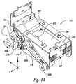
- FIG. 2Ais a top isometric view of a card dispenser 200 configured in accordance with an embodiment of the invention
- Figure 2Bis a top isometric view of the card dispenser 200 with a portion of a chassis 202 removed for clarity.
- the card dispenser 200can be used in a wide variety of kiosks, vending machines, and other machines for dispensing cards, such as wallet-sized credit cards, phone cards, in-store gift cards, etc.
- various embodiments of the card dispenser 200 disclosed hereincan be used with the kiosks and other card systems described in U.S. Patent Application Nos.: 10/504,438 , 10/504,436 , 10/504,437 , 11/294,637 , 10/558,907 , and 12/177,275 .
- the card dispenser 200can include a 5X5 array of card hoppers, a 6X3 array of card hoppers, etc. Accordingly, in other embodiments the card dispenser 200 can have other card hopper arrays and other overall dimensions. In these other embodiments, however, the card dispenser 200 can utilize the same card hopper assemblies 234, card carriage 212, controllers, positioning mechanisms, etc.
- the card dispenser 200includes a carriage positioning assembly 210 that can move a card carriage 212 in both the Y and Z directions as needed to position the card carriage 212 in front of a selected card hopper 232.
- the carriage positioning assembly 210includes a Y-axis support 214 that extends outwardly from a Z-axis shuttle 216.
- the Z-axis shuttle 216is movably coupled to a Z-axis support 204.
- the card carriage 212is movably coupled to the Y-axis support 214, and can move back and forth along the Y-axis relative to the Y-axis support 214.
- a customerselects a desired card using a keypad, touchpad, and/or other type of user interface on the kiosk or other type of particular machine in which the card dispenser 200 is positioned (not shown).
- the dispenser controller 240responds to the card selection by moving the card positioning assembly 210 up or down as needed along the Z-axis support 204 to position the card carriage 212 adjacent to the appropriate row of card hoppers 232.
- the controller 240moves the card carriage 212 left or right as needed along the Y-axis to position the card carriage 212 in front of the card hopper 232 holding the desired type of card.
- Figure 4is a bottom isometric view of the carriage positioning assembly 210 with the card carriage 212 and the scanner assembly 250 removed for clarity.
- the card carriage 212( Figure 3 ) is fixedly attached to a Y-axis shuttle 416.
- the Y-axis shuttle 416is movably coupled to the Y-axis support 214 by side edges 417a and 417b that are slidably received in corresponding slots 418a and 418b in the Y-axis support 214.
- the Y-axis shuttle 416is also attached to a direct drive belt 419 that is operably coupled to a drive pulley 426 and a driven pulley 428.
- the slider 516includes opposing grooves or slots 518 (identified individually as a first slot 518a and a second slot 518b) formed in opposing sidewalls thereof.
- the slots 518are configured to slidably receive opposing side edges 520 (identified individually as a first edge 520a and a second edge 520b) of the slot 521 formed in the bottom wall 592 of the card hopper 232 ( Figure 5A ).
- a card ejector plate 514is fixedly attached to an upper surface of the slider 516, and has a forward abutment feature or lip 522 configured to contact a rear edge portion 524 of the lower-most card 501 in the card stack.
- the dispenser controller 240( Figure 2B ) transmits a signal to the rotator 598 via the connector 536.
- the rotator 598rotates the slider pin 528 forward toward the -X direction. This drives the cam block 512 forward, which in turn causes the lip 522 of the ejector plate 514 to drive the card 501 out of the card hopper 232 via a card exit 596.
- Figure 6Ais an enlarged top isometric view of the card carriage 212
- Figure 6Bis a bottom isometric view of the card carriage 212.
- the card carriage 212includes a card transport assembly 620 that moves cards through the card carriage 212.
- the card transport assembly 620can include an X-axis motor 624 (e.g., a reversible 24VDC gear motor) that powers a drive pulley 626.
- a flat side portion 677 of the D-shaped intake roller 676initially faces toward the underside surface 680 of the card carriage 212, so that a leading edge 627 of the card 501 can enter the card carriage 212 through the card inlet 682 unimpeded.
- the X-axis motor 624drives the intake roller 676 in a first direction 678a, so that a round side portion 679 of the D-shaped roller 676 contacts the card 501 and pulls it from the respective hopper 232.
- the first drive rollers 630acontinue to move the card 501 forward under the card guide 684.
- the card exit sensor 670transmits this information to the dispenser controller 240.
- the dispenser controller 240can utilize this information to ascertain and control the position of the card 501 relative to the card carriage 212. For example, if the card 501 has not been properly read, the dispenser controller 240 can use the card position information from the sensor 670 to control the X-axis motor 624 (and the second drive rollers 630b) and move the card 501 back under the card reader 674 for a second attempt to read the card 501.
Landscapes
- Engineering & Computer Science (AREA)
- Business, Economics & Management (AREA)
- Mechanical Engineering (AREA)
- Physics & Mathematics (AREA)
- General Physics & Mathematics (AREA)
- Accounting & Taxation (AREA)
- Theoretical Computer Science (AREA)
- Strategic Management (AREA)
- General Business, Economics & Management (AREA)
- Finance (AREA)
- Microelectronics & Electronic Packaging (AREA)
- Computer Networks & Wireless Communication (AREA)
- Control Of Vending Devices And Auxiliary Devices For Vending Devices (AREA)
Description
- The following disclosure relates generally to systems, apparatuses and methods for dispensing cards, such as wallet-sized cards and the like from kiosks and other structures.
- Various types of vending machines and kiosks dispense prepaid credit cards, debit cards, phone cards, gift cards, and the like to customers. Such machines typically include a user interface for selecting a card, a monetary input device for receiving payment (e.g., a credit card reader or bill acceptor), and an outlet for dispensing the card to the customer. To purchase a card, the customer selects a desired card and deposits the required funds. Once the machine has confirmed payment, a card dispenser housed within the machine dispenses the desired card to the consumer via the outlet.
Figure 1 is an isometric view of acard dispenser 100 configured in accordance with the prior art. Thecard dispenser 100 includes acard hopper 102 containing a plurality ofcards 101, acard conveyor 104, acard reader 106, and acard outlet 108. In a typical card vending machine, thecard dispenser 100 is housed within the machine so that only thecard outlet 108 is exposed. In operation, after a user has selected a desired card and deposited the required funds, thecard conveyor 104 removes thebottom-most card 101 from thehopper 102 and moves the card forward past thecard reader 106.- As the card moves past the
card reader 106, thecard reader 106 reads information off a magnetic stripe on the card. The magnetic stripe can include one or more "tracks" of information. The information can include a unique code for associating the card with a particular account. For example, if the card is a prepaid credit card, then the code can be associated with a specific credit card account. Similarly, if the card is a prepaid phone card, then the code can be associated with a specific long-distance account. After moving past thecard reader 106, thecard conveyor 104 pushes the card through theoutlet 108 to the user. - One shortcoming of the prior
art card dispenser 100 is that it can only dispense a single type of card. As a result, additional card dispensers are required if more than one type of card is to be dispensed from a particular vending machine. Adding additional card dispensers, however, increases the cost, size, and weight of the vending machine. In addition, multiple card dispensers can increase the risk of card theft through the card outlets. US 2003/155370 A1 relates to apparatuses and methods for dispensing magnetic cards, integrated circuit cards, and other similar items. This document discloses a card dispensing apparatus that includes at least first and second card hoppers and a movable card carriage that can move back and forth along a first axis between the first and second card hoppers to selectively receive the bottom-most card from any one of the card hoppers. A stepper motor controls movement of the card carriage back and forth on a carriage track parallel to the first axis, and can selectively position the card carriage under any one of the card hoppers as required for card removal. The card carriage is configured to extract or remove the bottom-most card from the respective card hopper and move the card forward parallel to a second axis.US 6 597 970 B1 relates to an automated library kiosk. This document discloses a self-service kiosk having a walk-in enclosure, interactive selection panel, multi-section inventory storage area for dispensing items and accepting returns. User selections are entered via instructions entered at an interactive panel containing a selection menu of graphical icons and messages.US 5 857 588 A relates to an apparatus for dispensing tickets, cards and the like from a stack. This document discloses an apparatus for dispensing articles from a stack, the apparatus being particularly useful in dispensing articles having a leading edge, a trailing edge and a sensitive top or bottom surface.- It is therefore the object of the invention to provide an improved card dispensing apparatus and method for dispensing cards.
- This object is solved by the subject matter of the independent claims.
- Preferred embodiments are defined by the dependent claims.
Figure 1 is an isometric view of a card dispenser configured in accordance with the prior art.Figure 2A is an isometric view of a multi-hopper card dispensing apparatus configured in accordance with an embodiment of the disclosure, andFigure 2B is an isometric view of the card dispensing apparatus with a portion of a chassis removed for clarity.Figure 3 is an enlarged, top isometric view of a card carriage positioning assembly configured in accordance with an embodiment of the disclosure.Figure 4 is a bottom isometric view of the card carriage positioning assembly ofFigure 3 with selected structures removed for clarity.Figure 5A is an enlarged, top front isometric view of a card hopper assembly configured in accordance with an embodiment of the disclosure, andFigure 5B is a top rear isometric view of the card hopper assembly.Figure 6A is an enlarged top isometric view of a card carriage configured in accordance with an embodiment of the disclosure, andFigure 6B is a bottom isometric view of the card carriage.Figure 7 is a bottom isometric view of the card hopper assembly ofFigures 5A and5B ejecting a card into the card carriage ofFigures 6A and6B in accordance with an embodiment of the disclosure.Figure 8 is an isometric view of the card carriage positioning assembly ofFigure 3 , illustrating various aspects of a card scanner assembly configured in accordance with an embodiment of the disclosure.Figure 9 is a front isometric view of a card dispenser remote controller configured in accordance with an embodiment of the disclosure.Figure 10 is a front isometric view of a card vending structure that can include the card dispensing apparatus ofFigures 2A and2B .Figures 11A and 11B are flow diagrams illustrating a routine for dispensing a card from a kiosk or other enclosure in accordance with an embodiment of the disclosure.Figure 12A is a bottom isometric view of a card carriage having a card intake roller configured in accordance with another embodiment of the disclosure, andFigure 12B is an enlarged isometric view of the card intake roller ofFigure 12A .- The following disclosure describes apparatuses, systems and methods for dispensing various types of cards (e.g., wallet-sized credit cards, debit cards, phone cards, gift cards, and the like) and/or other items from vending machines, kiosks and/or other structures. The cards can have physical properties defined by one or more of the International Organization for Standardization (ISO) standards, which are commonly used for banking cards (ATM cards, credit cards, debit cards, etc.). The ISO standards can include ISO/IEC 7810 ID-1, ISO/IEC 7811, ISO/IEC 7812, ISO/IEC 7813, ISO 8583, and ISO 4909. These standards can define, for example, card size (e.g., 3.370 in. x 2.125 in.), card flexibility, and magstripe location, magnetic characteristics and data formats. The ISO standards can also provide standards for financial cards, including the allocation of card number ranges to different card issuing institutions. In addition or alternatively, the cards can also include features defined by the ABA (American Banking Association) CR-80 standard. The apparatuses, systems and methods disclosed herein can also include various features for reading information from, and for writing information to, various types of storage media on cards. Such media can include, for example, magnetic media (e.g., magnetic stripes or "magstripes") complying with one or more ISO standards, optical media, barcodes, memory chips, embedded integrated circuits, radio frequency tags, transponder devices, etc.
- Certain embodiments of the apparatuses and methods of the invention described herein are described in the context of computer-executable instructions performed by a general-purpose computer or other processing equipment. These computer-executable instructions can be stored on a computer-readable medium, such as a floppy disk, hard disk, CD-ROM, etc. These instructions can be stored on a server computer system and accessed via a communications link or a computer network, such as an intranet, the Internet, or other computer network. Because the basic structures and functions related to computer-readable routines and corresponding implementations are known, they have not been shown or described in detail here to avoid unnecessarily obscuring the described embodiments of the invention.
- Certain details are set forth in the following description and in
Figures 2A-9 to provide a thorough understanding of various embodiments of the invention. Those of ordinary skill in the relevant art will appreciate, however, that the invention can have additional embodiments that may be practiced without several of the details described below. In addition, some well-known structures and systems often associated with card dispensing apparatuses and methods have not been shown or described in detail below to avoid unnecessarily obscuring the description of the various embodiments of the invention. - The dimensions, angles, and other specifications shown in the figures are merely illustrative of particular embodiments of the invention. Accordingly, other embodiments of the invention can have other dimensions, angles, and specifications.
- In the drawings, identical reference numbers identify identical, or at least generally similar elements. To facilitate the discussion of any particular element, the most significant digit or digits in any reference number refers to the figure in which that element is first introduced. For example,
element 210 is first introduced and discussed with reference toFigure 2 . Figure 2A is a top isometric view of acard dispenser 200 configured in accordance with an embodiment of the invention, andFigure 2B is a top isometric view of thecard dispenser 200 with a portion of achassis 202 removed for clarity. Thecard dispenser 200 can be used in a wide variety of kiosks, vending machines, and other machines for dispensing cards, such as wallet-sized credit cards, phone cards, in-store gift cards, etc. For example, various embodiments of thecard dispenser 200 disclosed herein can be used with the kiosks and other card systems described inU.S. Patent Application Nos.: 10/504,438 ,10/504,436 10/504,437 11/294,637 10/558,907 12/177,275 - Referring to
Figures 2A and2B together, in one aspect of this embodiment thecard dispenser 200 includes acard hopper array 230 that includes a plurality of individual card hopper assemblies 234 (identified individually ascard hopper assemblies 234a-234o). Eachcard hopper assembly 234 includes a corresponding card hopper 232 (identified individually ascard hoppers 232a-232o). In the illustrated embodiment, each of thecard hoppers 232 is configured to hold at least about 50 wallet-sized cards (not shown), such as .030 inch thick flat or embossed style cards. Each card can include a magnetic stripe (e.g., a conventional magnetic stripe with three tracks of data), one or more barcodes (in, e.g., various different formats), etc. In other embodiments, the cards can have other sizes and other information storage features. - In the illustrated embodiment, the
card hoppers 232 are arranged in a 3X5 array made up of three vertical columns of five hoppers each. In this configuration, thecard dispenser 200 has a relatively compact overall size with a width W, a length L, and a height H. In the illustrated embodiment, the width W can be from about 7 inches to about 10 inches, or about 8.25 inches; the length L can be from about 10 inches to about 15 inches, or about 13.5 inches; and the height H can be from about 17 inches to about 24 inches, or about 21.75 inches. Because of the versatile design of thecard dispenser 200, however, in other embodiments thecard dispenser 200 can include more or fewer card hoppers in different arrays. For example, in other embodiments thecard dispenser 200 can include a 5X5 array of card hoppers, a 6X3 array of card hoppers, etc. Accordingly, in other embodiments thecard dispenser 200 can have other card hopper arrays and other overall dimensions. In these other embodiments, however, thecard dispenser 200 can utilize the samecard hopper assemblies 234,card carriage 212, controllers, positioning mechanisms, etc. - In another aspect of this embodiment, the
card dispenser 200 includes acarriage positioning assembly 210 that can move acard carriage 212 in both the Y and Z directions as needed to position thecard carriage 212 in front of a selectedcard hopper 232. Thecarriage positioning assembly 210 includes a Y-axis support 214 that extends outwardly from a Z-axis shuttle 216. The Z-axis shuttle 216 is movably coupled to a Z-axis support 204. As described in greater detail below, thecard carriage 212 is movably coupled to the Y-axis support 214, and can move back and forth along the Y-axis relative to the Y-axis support 214. The Z-axis shuttle 216 can move up and down along the Z-axis relative to the Z-axis support 204. A card dispenser controller 240 (e.g., a first circuit card assembly) is operably coupled to thecarriage positioning assembly 210 via a flexible cable 244 (e.g., a ribbon cable). Thedispenser controller 240 is also coupled to a remote controller 242 (e.g., a second circuit card assembly) and a carriage controller (not shown inFigures 2A or2B ). - In one embodiment of operation, a customer selects a desired card using a keypad, touchpad, and/or other type of user interface on the kiosk or other type of particular machine in which the
card dispenser 200 is positioned (not shown). After confirming payment for the card, thedispenser controller 240 responds to the card selection by moving thecard positioning assembly 210 up or down as needed along the Z-axis support 204 to position thecard carriage 212 adjacent to the appropriate row ofcard hoppers 232. In addition, thecontroller 240 moves thecard carriage 212 left or right as needed along the Y-axis to position thecard carriage 212 in front of thecard hopper 232 holding the desired type of card. As described in greater detail below, the card is then ejected by the correspondingcard hopper assembly 234 into thecard carriage 212. Thecard carriage 212 then draws the card inward and past an optional card reader (e.g., a magnetic stripe reader) to read information from data storage media (e.g., a magnetic stripe) on the card. In other embodiments, thecard carriage 212 can include a card writer (e.g., a write head) that can write information onto storage media, such as a magnetic media, optical media, and/or an IC. Once properly read (or written to), the card information can be used to activate the card (via, e.g., a remote database), track the sale of the card, retrieve a PIN associated with a card account, generate a receipt, and/or perform other useful functions known in the art. As described in greater detail below, thecarriage positioning assembly 210 can also include an optional scanner assembly 250 (having, e.g., a barcode scanner) for scanning and decoding machine-readable indicia on the card (e.g., a barcode containing a card number for inventory tracking purposes, a card price, a card type, etc.) after the card is withdrawn from therespective hopper 232. - Once the card information has been properly read (if necessary), the
carriage positioning assembly 210 positions thecard carriage 212 above a card acceptchute 260a, and thecard carriage 212 dispenses the card into the acceptchute 260a. From the card acceptchute 260a, the card travels to an outlet (not shown) for retrieval by the customer. Conversely, if the card has not been properly read after one or more tries, thecard carriage 212 drops the card into acard reject chute 260b. Thecard carriage 212 then returns to theappropriate card hopper 232 and retrieves another card for dispensing to the customer. Figure 3 is an enlarged isometric view of thecarriage positioning assembly 210 configured in accordance with an embodiment of the invention. Arack 306 having a row ofteeth 307 is fixedly attached to the Z-axis support 204. A Z-axis motor 320 (e.g., an electric motor, such as a bipolar stepper motor) is attached to a proximal end portion of the Y-axis support 214, and drives aspur gear 308 that engages theteeth 307 on therack 306. Themotor 320 responds to electrical signals from the dispenser controller 240 (Figure 2A ) via thecable 244 by moving thecarriage assembly 210 up or down as required along the Z-axis.- A Y-axis motor 322 (e.g., an electric motor, such as a bipolar stepper motor) is attached to a distal end portion of the Y-
axis support 214. The Y-axis motor 322 responds to signals from thedispenser controller 240 by moving thecard carriage 212 back and forth as required along the Y-axis. As this view illustrates, the dispenser controller 240 (Figures 2A and2B ) is also connected to a card carriage controller 344 (e.g., a third circuit card assembly) via thecable 244. As described in greater detail below, thecard carriage 212 responds to signals from thedispenser controller 240 via thecard carriage controller 344. The signals cause thecard carriage 212 to receive selected cards from thecard hoppers 232 and dispense the cards into the appropriate chute 260 (Figure 2A ). Figure 4 is a bottom isometric view of thecarriage positioning assembly 210 with thecard carriage 212 and thescanner assembly 250 removed for clarity. The card carriage 212 (Figure 3 ) is fixedly attached to a Y-axis shuttle 416. The Y-axis shuttle 416 is movably coupled to the Y-axis support 214 byside edges 417a and 417b that are slidably received in correspondingslots axis support 214. The Y-axis shuttle 416 is also attached to adirect drive belt 419 that is operably coupled to a drivepulley 426 and a drivenpulley 428. The Y-axis motor 322 can rotate thedrive pulley 426 in either direction as necessary to move the Y-axis shuttle 416 back and forth as desired along the Y-axis. A Y-axis sensor (e.g., a reflective infrared (IR) sensor) detects the position of the Y-axis shuttle 416 when the Y-axis shuttle 416 is in a "home" position toward the distal end of the Y-axis support 214. After ascertaining the home position, an incremental encoder (not shown) affixed to the Y-axis motor 322 can position the Y-axis shuttle 416 at any desired location along the Y-axis support 214 relative to the home position.- One or more biasing members 472 (e.g., constant force springs) can be wound around a
spool 470 that is rotatably attached to the Z-axis shuttle 216. Adistal end portion 473 of the one ormore biasing members 472 can be fixedly attached to the Z-axis support 204 at a location above the uppermost position of thecarriage positioning assembly 210. By virtue of the constant or near constant force in the biasingmembers 470, they can offset and/or neutrally balance the weight of thecarriage positioning assembly 210 as it moves up and down along the Z-axis support 204 during operation of thecard dispenser 200. This reduces the workload on the Z-axis motor 320 (Figure 3 ). In other embodiments, however, other biasing member configurations and other means can be used to neutrally balance or offset the weight of thecarriage positioning assembly 210, or the offsetting means can be omitted. Figure 5A is a top front isometric view of one of thecard hopper assemblies 234 configured in accordance with an embodiment of the invention, andFigure 5B is a top rear isometric view of thecard hopper assembly 234. Referring first toFigure 5A , eachcard hopper assembly 234 includes acorresponding card hopper 232. Thecard hopper 232 includes opposing side walls 590 (identified individually as afirst sidewall 590a and asecond sidewall 590b) and arear wall 590c extending therebetween. Thecard hopper 232 also includes abottom wall 592 that includes aslot 521 and acutout 523. Although only asingle card 501 is shown lying horizontally in thecard hopper 232 for purposes of illustration, those of ordinary skill in the art will appreciate that thecard hopper 232 is configured to hold a stack of cards, e.g., a vertical stack of at least 30 cards.- Referring next to
Figure 5B , thecard hopper assembly 234 further includes acard ejector assembly 530. Thecard ejector assembly 530 includes a rotator 598 (e.g., a rotary solenoid) that is electrically connected to the dispenser controller 240 (Figures 2A and2B ) via a quickdisconnect cable connector 536. Therotator 598 includes aslider pin 528 that extends downwardly from arotating arm 526. Theslider pin 528 extends into atransverse slot 538 formed in acam block 512 which is fixedly attached to aslider 516. Theslider 516 includes opposing grooves or slots 518 (identified individually as afirst slot 518a and asecond slot 518b) formed in opposing sidewalls thereof. The slots 518 are configured to slidably receive opposing side edges 520 (identified individually as afirst edge 520a and asecond edge 520b) of theslot 521 formed in thebottom wall 592 of the card hopper 232 (Figure 5A ). Acard ejector plate 514 is fixedly attached to an upper surface of theslider 516, and has a forward abutment feature orlip 522 configured to contact arear edge portion 524 of thelower-most card 501 in the card stack. In operation, the dispenser controller 240 (Figure 2B ) transmits a signal to therotator 598 via theconnector 536. In response to the signal, therotator 598 rotates theslider pin 528 forward toward the -X direction. This drives thecam block 512 forward, which in turn causes thelip 522 of theejector plate 514 to drive thecard 501 out of thecard hopper 232 via acard exit 596. - Embossed cards can sometimes stack unevenly. In addition, the embossed numbers and/or letters on such cards can sometimes nest together (especially if the cards are sequentially numbered), and this can cause the cards to interlock or stick together at the mating surfaces. One advantage of embodiments of employing a rotary solenoid for the
rotator 598 is that the relatively high power and quick motion of the rotary solenoid can overcome the interlock between the bottom card and the adjacent card above. This can facilitate quick card ejection and reduce binding of the ejection mechanism. - In the illustrated embodiment, each
hopper assembly 234 is designed to be detachably "clicked" into a rear portion of the chassis 202 (Figure 2A ) from the front side. To accomplish this, the aft end portion of thehopper assembly 234 can include a plurality of releasable attachment features 532 (identified individually as afirst attachment feature 532a, asecond attachment feature 532b, and athird attachment feature 532c). In the illustrated embodiment, the attachment features 532 can include ball studs that fit into corresponding Tinnerman fasteners on the dispenser chassis 202 (not shown). This "Plug and Play" concept makes the card hopper array 230 (Figures 2A and2B ) easy to assemble and easy to service from one side without tools. In other embodiments, other suitable fasteners and features known in the art can be used to attach the hopper assemblies to thechassis 202 including, for example, captive screws, captive nuts, and/or metal tabs. Figure 6A is an enlarged top isometric view of thecard carriage 212, andFigure 6B is a bottom isometric view of thecard carriage 212. Referring first toFigure 6A , in one aspect of this embodiment thecard carriage 212 includes acard transport assembly 620 that moves cards through thecard carriage 212. Thecard transport assembly 620 can include an X-axis motor 624 (e.g., a reversible 24VDC gear motor) that powers adrive pulley 626. Thedrive pulley 626 is operably engaged with aserpentine drive belt 618 that is operably wrapped around an associated system of driven pulleys 628 (identified individually as a first drivenpulley 628a, a second drivenpulley 628b, a third drivenpulley 628c, and a fourth drivenpulley 628d) and twoidler pulleys 629.- Referring to
Figures 6A and6B together, the first drivenpulley 628a is operably coupled to a card intake roller 676 (shown in partial section view inFigure 6B ) that extends transversely across thecard carriage 212. In one aspect of this embodiment, theintake roller 676 can include a compressible (e.g., rubber) exterior surface with a "D"-shaped cross section. In other embodiments, theintake roller 676 and/or variations thereof can have other cross-sectional shapes, such as obround shapes, oval shapes, etc. Moreover, theintake roller 676 can include one ormore rubber cords 681 a, b that extend along all or a portion of the length of the roller to contact and withdraw the cards from thecard hopper assembly 234. In the illustrated embodiment, for example, the cords 681 are arranged at about 180 degrees from each other and about 90 degrees from aflat side portion 677 of the D-shapedintake roller 676. In other embodiments, the cords 681 can have other shapes, sizes, and number, or they can be omitted. - The second driven
pulley 628b drives a first shaft, to which one or morefirst drive rollers 630a are operably coupled, and the third drivenpulley 628c drives a second shaft, to which one or moresecond drive rollers 630b are operably coupled. In another aspect of this embodiment, the drive rollers 630 can include compressible (e.g., rubber) exterior surfaces. Acard guide 684 is positioned between the two sets of drive rollers 630 and carries a reader 674 (e.g., a magnetic read head). In other embodiments, thecard carriage 212 can include a card writer (e.g. a write head) for writing information (e.g., an account number, PIN, etc.) to a card. Thecard guide 684 and thereader 674 can be space apart from anunderside surface 680 of thecard carriage 212 to form a slight gap therebetween that thecard 501 can pass through. - A
forward bulkhead 690 is fixedly attached to a front portion of thecard carriage 212 and carries afirst sensor 686a (e.g., a first IR reflective sensor) and asecond sensor 686b (e.g., a second IR reflective sensor). The sensors 686 can each include aninfrared source 687a and aninfrared receiver 687b. Theinfrared source 687a emits a beam of infrared light that reflects off of objects in front of the card carriage 212 (e.g., a stack of cards) and is detected by theinfrared receiver 687b. In operation, the sensors 686 detect the position of thecard carriage 212 relative to a selectedcard hopper 232, and transmit this information to thedispenser controller 240. The sensors 686 are vertically offset in the illustrated embodiment to facilitate determining the top and bottom of card stacks. Thedispenser controller 240 uses the information from the sensors 686 to accurately position thecard carriage 212 in the proper location to receive the bottom-most card from therespective card hopper 232 via acard inlet 682. - As described in greater detail below, a
flat side portion 677 of the D-shapedintake roller 676 initially faces toward theunderside surface 680 of thecard carriage 212, so that aleading edge 627 of thecard 501 can enter thecard carriage 212 through thecard inlet 682 unimpeded. Once thecard 501 is beneath theintake roller 676, theX-axis motor 624 drives theintake roller 676 in afirst direction 678a, so that around side portion 679 of the D-shapedroller 676 contacts thecard 501 and pulls it from therespective hopper 232. Thefirst drive rollers 630a continue to move thecard 501 forward under thecard guide 684. As thecard 501 passes beneath thecard reader 674, thereader 674 can read information from data storage media 608 (e.g., a magnetic stripe). After passing under thecard reader 674, thesecond drive rollers 630b can eject thecard 501 through acard exit 688. - As the
leading edge 627 of thecard 501 moves toward thecard exit 688, it depresses a sensor switch or lever 671 operably coupled to a card exit sensor 670 (Figure 6A ). As described in greater detail below, thecard exit sensor 670 transmits this information to thedispenser controller 240. Thedispenser controller 240 can utilize this information to ascertain and control the position of thecard 501 relative to thecard carriage 212. For example, if thecard 501 has not been properly read, thedispenser controller 240 can use the card position information from thesensor 670 to control the X-axis motor 624 (and thesecond drive rollers 630b) and move thecard 501 back under thecard reader 674 for a second attempt to read thecard 501. Moreover, when thecard 501 has been ejected from thecard carriage 212 and thesensor lever 671 returns to its initial position, thedispenser controller 240 can control theX-axis motor 624 to return the D-shapedintake roller 676 to its proper "start" position. This can be accomplished in one embodiment by anabsolute encoder 672 operably coupled to the fourth drivenpulley 628d. When theabsolute encoder 672 determines that thedrive belt 618 has reached a position in which theintake roller 676 is oriented with theflat side portion 677 facing toward thecard carriage surface 680, theencoder 672 sends a signal to thedispenser controller 240 to stop themotor 624. Figure 7 is a bottom isometric view of thecard hopper assembly 234 as it ejects thecard 501 into thecard carriage 212, in accordance with an embodiment of the invention. To transfer thecard 501 from thecard hopper 232 to thecard carriage 212, thecontroller 240 positions thecard carriage 212 so that the card inlet 682 (Figure 6B ) is positioned directly in front of thecard exit 596 of the card hopper 232 (Figure 5A ). Thecard ejector assembly 530 then drives the card 501 a preselected distance (e.g., about one inch) into thecard carriage 212 through theinlet 682 as described above with reference toFigures 5A and5B . After driving thecard 501 forward, a biasing member 740 (e.g., a coil spring) retracts theslider 516 as therotator 598 drives thecam block 512 back in the +X direction.- The
card intake roller 676 is initially positioned with the flat side portion 677 (Figure 6B ) facing toward thecard carriage 212 to form a gap between theflat side portion 677 and theunderside surface 680 of thecard carriage 212. Once thecard ejector assembly 530 drives the card 501 a preset distance through this gap, thecontroller 240 activates the X-axis motor 624 (Figure 6A ), causing theintake roller 676 to rotate in thefirst direction 678a (Figure 6B ) and draw thecard 501 into thecard carriage 212. Thefirst drive rollers 630a continue moving thecard 501 in the -X direction and under thecard guide 684 so that thereader 674 can read themagnetic stripe 608. In other embodiments, a write head or similar device known in the art (not shown) can write information to themagnetic stripe 608 or other storage media on thecard 501 as it passes under thecard guide 684. - If the
card reader 674 does not adequately read themagnetic stripe 608, thecontroller 240 can command the X-axis motor 624 (Figure 6A ) to reverse direction of the drive rollers 630 and move themagnetic stripe 508 back under thecard reader 624 in a second attempt to read themagnetic stripe 608. Thecard sensor switch 671 tells thecontroller 240 what the position of thecard 501 is during this procedure and thecontroller 240 controls the drive rollers 630 accordingly. This prevents the drive rollers 630 from moving thecard 501 too far in either direction. This process can be repeated until themagnetic stripe 608 has been adequately read, or until a preset number of attempts have failed and thecard 501 is determined to be defective. - As described in greater detail below, the
card 501 can also include machine-readable indicia, such as abarcode 750 that can be automatically read and/or decoded by the scanner assembly 250 (Figure 2A ). To read thebarcode 750, thecard carriage 212 can move thecard 501 along the X-axis as needed to position thebarcode 750 in a scanner envelope (not shown inFigure 7 ). In addition or alternatively, the Y-axis shuttle 416 (Figure 4 ) can move thecarriage 212 along the Y-axis as needed to position thebarcode 750 in the scanner envelope. - Once the
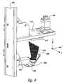
magnetic stripe 608 and/or thebarcode 750 have been adequately read, thecarriage positioning assembly 210 moves thecard carriage 212 into position over the card acceptchute 260a (Figure 2A ). The drive rollers 630 then eject thecard 501 through thecard exit 688, and thecard 501 falls into the card acceptchute 260a for retrieval by the user. Alternatively, if themagnetic stripe 608 and/or thebarcode 750 cannot be read or thecard 501 is otherwise determined to be unusable, thecard carriage 212 moves into position and ejects thecard 501 into thecard reject chute 260b. If thecard 501 is rejected, thecard carriage 212 can return to thecard hopper 232 to obtain another one of the selected cards to dispense to the user. Figure 8 is a rear isometric view of thescanner assembly 250 configured in accordance with an embodiment of the invention. Thescanner assembly 250 can include a reader 852 (e.g., an optical scanner with decoder circuitry) and a reflective surface ormirror 856 mounted to asupport member 850. Thesupport member 850 is fixedly attached to the Z-axis shuttle 216 (Figure 3 ), and accordingly moves up and down with the Z-axis shuttle 216.- The
reader 852 can be capable of reading several different types of indicia (e.g., several different styles of barcode images) that may be present on the bottom side of thecard 501. In one embodiment, thereader 852 can include a barcode scanner or reader (e.g., an Opticon NLV-1001) which uses a laser to scan a code symbol and has an onboard decoder to decipher the information before sending it to thedispenser controller 240. The Opticon NLV-1001 laser barcode scanner is capable of decoding the following 1 D symbols: JAN/UPC/EAN (WPC incl. add-on), Chinese Post, Codabar/NW-7, Code 11, Code 39, Code 93, Code 128, IATA, Industrial 2of5, Interleaved 2of5, ISBN-ISMN-ISSN, Korean Post, Matrix 2of5, MSI/Plessey-UK/Plessey, RSS, S-Code, Telepen, Tri-Optic, Composite Codes, and the following 2D symbols : MicroPDF417, PDF417. - In the illustrated embodiment, the
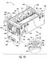
mirror 856 is positioned at an angle (e.g., a 45 degree angle) in front of thereader 852. As a result, when thereader 852 projects light (e.g., laser light) in ascan envelope 854, the light reflects off themirror 856 to orient thescan envelope 854 at an angle of 90 degrees, or about 90 degrees, to theunderside surface 680 of the card carriage 212 (Figures 6B and7 ), thereby saving space. Thecard 501 can be centered, or at least approximately centered, against the underside of thecard carriage 212. The Y-axis motor 322 can then move the Y-axis shuttle back and forth along the Y-axis as necessary to move the barcode 750 (Figure 7 ) into thescan envelope 854 of thestationary reader 852 so that thereader 852 can suitably read thebarcode 750. Thecard carriage 212 can be configured so that the entire portion of thecard 501 where thebarcode 750 or other indicia is printed is free of obstruction and therefore easily scanned. In other embodiments, the card dispenser 200 (Figures 2A and2B ) can include other types of known reading devices for reading barcodes, magnetic stripes, and/or other indicia and data storage devices on cards. Figure 9 is an enlarged isometric view of the card dispenserremote controller 242 configured in accordance with an embodiment of the invention. As shown inFigure 2A , theremote controller 242 is positioned on an accessible region of thecard dispenser chassis 202. Theremote controller 242 allows manual testing and operation of thecard dispenser 200 by a service person or other operator (not shown), and enables the operator to assess system health via one or more status lights 962 (e.g., light emitting diodes (LEDs); identified individually aslights 962a-c). Theremote controller 242 includes a plurality of manually operable actuators or buttons 960 that the operator can press to operate and/or test various functionalities of thecard dispenser 200. For example, theremote controller 242 can include a "home"button 960a that the operator can depress to return thecarriage positioning assembly 210 to its home position. Theremote controller 242 can also include an "up"button 960b to test movement of thecarriage positioning assembly 210 upward along the Z-axis. Theremote controller 242 can similarly include "left," "right," and "down" buttons, as well as a "read card"button 960c for testing the ability of thereader 674 to read data storage media such as magnetic stripes. Theremote controller 242 can also include a "reverse"button 960d and a "forward"button 960e for testing the reverse and forward motion, respectively, of the drive rollers 630 on the card carriage 212 (Figure 6B ). An "align roller"button 960f can be used to test the alignment capability of the flat side portion of the card intake roller 676 (Figure 6B ), and a "self test"button 960g can be used to initiate an automatic self test of thecard dispenser 200.Figure 10 is a front isometric view of an example of akiosk 1010 that can include thecard dispenser 200 described in detail above. In one aspect of this embodiment, thekiosk 1010 can include features at least generally similar in structure and function to corresponding features of the coin-counting machines and kiosks described inU.S. Patent No. 6,494,776 ,U.S. Patent No. 6,957,746 , andU.S. Patent Application No. 11/294,652 . In other embodiments, however, various aspects of thekiosk 1010 can differ from the machines and kiosks described in these references depending on the particular application. Moreover, in other embodiments, thecard dispenser 200 described herein can be used with other kiosks, vending machines, etc.- In another aspect of this embodiment, the
kiosk 1010 includes adisplay screen 1013 positioned proximate to auser interface 1052. Theuser interface 1052 includesuser selection buttons 1014 and akeypad 1011. Thedisplay screen 1013 can display various user instructions and prompts explaining how to purchase cards and/or perform other functions with thekiosk 1010. Theuser selection buttons 1014 can include, for example, various options for responding to the prompts and selecting a desired type of card or a desired method of payment. Similarly, thekeypad 1011 can allow the user to input various alphanumeric information, such as account numbers and/or monetary values, related to the card purchase transaction. - In a further aspect of this embodiment, the
kiosk 1010 also includes a coin input region ortray 1015 configured to receive a plurality of coins from a user for counting. In one embodiment, the user can elect to receive a redeemable voucher via anoutlet 1016 for a value related to the total amount of coins counted. In another embodiment, the user can elect to pay for a card (such as a prepaid credit card or phone card) with coins in addition to or as an alternative to paying for the card with a credit card via a card reader 1022 (e.g., a conventional card swipe) or with paper currency via abill acceptor 1020. - A user desiring to purchase a card from the
kiosk 1010 may do so by first reading the card purchase instructions and prompts displayed on thescreen 1013. (Alternatively, the instructions can be provided on the front or side of thekiosk 1010 along with product advertising and/or other graphics.) By using theselection buttons 1014 and/or thekeypad 1011 to respond to the prompts, the user can select a particular type of card (e.g., a credit card, debit card, phone card, etc.) and/or a particular card value. In one embodiment, the available card values (e.g., the prepaid amount of money or prepaid long-distance minutes associated with a card) can be predefined such that the user must choose from a limited number of options. In other embodiments, the value may be variable such that the user may be able to specify a particular card value. In either embodiment, the user then enters payment (e.g., via thecoin input tray 1015, thecard reader 1022, and/or the bill acceptor 1020) sufficient to cover the cost of the selected card. Once thekiosk 1010 confirms receipt of payment, thecard dispensing apparatus 200 dispenses the desired card of the desired value to the user via acard outlet 1070 associated with the card acceptchute 260a (Figure 2A ). - In one embodiment, the
kiosk 1010 can be networked via acentral computer 1050 to other card vending machines and/or remote computer systems to exchange information related to card purchases. Such information can include, for example, bank account and credit/debit card account information, in addition to long-distance calling card account information. In another embodiment, thekiosk 1010 can be networked to one or more remote computer systems and configured to transmit an appropriate signal when the machine is out of one or more types of cards. Service personnel with access to the remote computer system can then respond to the signal by restocking the machine with the needed cards. Similar signals can be transmitted from thekiosk 1010 to the remote computer when the machine is malfunctioning, jammed, full of coins or other currency, and/or subject to theft, vandalism, or another form of tampering. - In another embodiment, the
card carriage 212 can serve as a card reader for use by the customer when making purchases with an existing credit/debit card. In this embodiment, thecard reader 1022 can be replaced by a card slot (not shown) on the front of thekiosk 1010. To make a new card purchase with an existing card, the user inserts their existing credit/debit card into the slot, and the card is drawn into thecard carriage 212 and read. After the card has been read, the card carriage returns the card to the customer. Once the credit/debit card transaction has been approved, thecard carriage 212 dispenses the new card to the customer as described in detail above. Accordingly, in this embodiment, thecard carriage 212 and associated systems serve as both a card reader for use by customers as well as a card dispenser. This can eliminate the cost of theadditional card reader 1022 on the front of thekiosk 1010. Figure 11A is a flow diagram illustrating a routine 1100A for dispensing a selected card to a user with thecard dispenser 200 ofFigures 2A and2B , in accordance with an embodiment of the invention. In one aspect of this embodiment, the routine 1100A can be carried out by the central computer 1050 (Figure 10 ) according to computer-executable instructions stored on a computer-readable medium, such as a floppy disk, CD-ROM, integrated circuit chip, etc. The routine 1100A starts when thecentral computer 250 receives a request for a particular type of card. This request may come from theuser interface 1052 which, as described above, can include a keypad, touch screen, and/or other user selection buttons. In response to the card request, inblock 1102, the routine 1100A prompts the user for payment for the card. Such payment can include cash received in the form of coins or bills, credit received in the form of a credit card account number, and/or debit in the form of a debit card account number. In other embodiments, cards can be purchased using other forms of payment, including voucher and/or prepayment from a remote computer via a computer network or an associated web site.- In
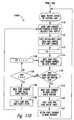
decision block 1104, the routine 1100A determines if payment for the card has been received from the user or otherwise confirmed. If payment has not been received, then indecision block 1106 the routine 1100A determines if the transaction should be terminated. In one embodiment, the routine 1100A can elect to terminate the transaction based on the amount of time that has elapsed without receiving payment from the user. In other embodiments, termination can be based on other factors, such as user termination input or lack of a user response to an appropriate prompt. If, however, the routine 1100A determines that the transaction should not be terminated, then the routine 1100A continues to wait for user payment and/or it can reprompt the user for payment. Once the routine 1100A confirms that payment has been received, the routine proceeds to block 1108 and signals the card dispenser controller 240 (Figures 2A and2B ) to issue the selected card to the user. Figure 11B is a flow diagram illustrating a routine 1100B that continues from routine 1100A. In one aspect of this embodiment, the routine 1100B can be carried out by the card dispenser controller 240 (Figures 2A and2B ) when it receives an instruction from thecentral computer 1050 to dispense a particular card to the user. Inblock 1110, the routine 1100B responds to the instruction by moving thecard carriage 212 into position in front of thecard hopper 232 that contains the desired card type. Inblock 1112, thecard hopper assembly 234 ejects the bottom-most card in thecard hopper 232 into the card carriage 212 (see, e.g.,Figure 7 ).- In
block 1113, the routine 1100B sets a counter toi = 1. Next, inblock 1114, the routine 1100B moves the card so that the magnetic stripe or other data storage media on the card passes under the card reader 674 (and/or a card writer). Indecision block 1116, the routine 1100B determines if the card was sufficiently read by the card reader 674 (or sufficiently written to by a card writer, if applicable). If so, then the routine 1100B proceeds to block 1118 and moves thecard carriage 212 into position relative to the card acceptchute 260a. Inblock 1120, the routine 1100B ejects the card into the card acceptchute 260a, from where the card passes to the card outlet chute 1070 (Figure 10 ) for retrieval by the user. Inblock 1122, the routine 1100B returns thecard carriage 212 to the home position, and awaits another signal to dispense a card. - Returning to
decision block 1116, if the card was not sufficiently read (or written to) by thecard reader 674, then the routine 1100B proceeds todecision block 1124 and determines ifi = η. Here, η can be a preselected number of times that a given card will be passed by thecard reader 674 in an attempt to sufficiently read (or write to) the card before the card is rejected. In one embodiment, for example, η can be three. In other embodiments, η can have other values (e.g., 2, 4, 6, 10, etc.) depending on other factors. Ifi does not equal η atdecision block 1124, then the routine 1100B proceeds to block 1126 and incrementsi by one. Next, the routine 1100B returns to block 1114 and repeats. Ifi does equal η atdecision block 1124, then the routine 1100B proceeds to block 1128 and moves thecard carriage 212 into position relative thecard reject chute 260b. Inblock 1130, the routine 1100B ejects the unread card into thecard reject chute 260b. The card rejectchute 260b can lead to an escrow bin that holds rejected cards for retrieval by a machine service person. Fromblock 1130, the routine 1100B returns to block 1110 and repeats until the desired card has been provided to the user (or until the machine runs out of the desired card type). Figure 12A is a bottom isometric view of acard carriage 1212 having acard intake roller 1276 configured in accordance with another embodiment of the invention, andFigure 12B is an enlarged isometric view of thecard intake roller 1276. Referring toFigures 12A and 12B together, thecard carriage 1212 is at least generally similar in structure and function to thecard carriage 212 described in detail above. For example,Figure 12A is a bottom isometric view of acard carriage 1212 having acard intake roller 1276 configured in accordance with another embodiment of the disclosure, andFigure 12B is an enlarged isometric view of thecard intake roller 1276. Referring toFigures 12A and 12B together, thecard carriage 1212 is at least generally similar in structure and function to thecard carriage 212 described in detail above. For example, thecard intake roller 1276 is driven by the first drivenpulley 628a which is operably coupled to acentral shaft 1280 of thecard intake roller 1276. In this particular embodiment, however, thecard intake roller 1276 has an oval or obround cross-sectional shape with opposing first and secondflat side portions 1277a, b, and opposing first and secondround side portions 1279 a, b. In one aspect of this embodiment, the round side portions 1279 can be formed fromcompressible members 1284a, b (e.g., rubber cords) having circular cross-sections. The compressible members 1284 are held in appropriately-shaped recesses in thebody 1282 of theroller 1276, so that a portion of each member is exposed to form a compressible, rounded outer surface of theintake roller 1276.- In operation, the flat side portions 1277 of the
intake roller 1276 initially face toward the underside surface of thecard carriage 1212, so that the leading edge of a card can pass under theroller 1276 unimpeded. Once the card is beneath theintake roller 1276, the X-axis motor 624 (Figure 6A ) drives theintake roller 1276 in a first direction so that one of the round side portions 1279 contacts the card and pulls it from therespective hopper 232. Thefirst drive rollers 630a continue to move the card forward under the card guide 684 (Figure 6B ). The card proceeds through thecard carriage 1212 as described above with reference to thecard carriage 212. - Unless the context clearly requires otherwise, throughout the description and the claims, the words "comprise," "comprising," and the like are to be construed in an inclusive sense as opposed to an exclusive or exhaustive sense; that is to say, in the sense of "including, but not limited to." Words using the singular or plural number also include the plural or singular number respectively. Additionally, the words "herein," "above," "below," and words of similar import, when used in this application, shall refer to this application as a whole and not to any particular portions of this application. When the claims use the word "or" in reference to a list of two or more items, that word covers all of the following interpretations of the word: any of the items in the list, all of the items in the list, and any combination of the items in the list.
Claims (8)
- A card dispensing apparatus (200) comprising:an array (230) of card hoppers, wherein the array of card hoppers includes at least two vertical columns of card hoppers positioned side by side, wherein each vertical column includes two or more card hoppers (232), and wherein each of the individual card hoppers is configured to hold a plurality of horizontally oriented cards (501) in a vertical stack;a plurality of card ejectors, wherein each of the card ejectors is fixed to a corresponding one of the card hoppers; anda card carriage (212) selectively movable between each of the card hoppers, wherein the card carriage is configured to respond to a card selection by moving into position proximate a corresponding one of the card hoppers, wherein the card ejector operably associated with the corresponding card hopper is configured to eject one of the cards from the corresponding card hopper in response to a signal associated with the card selection, wherein the card carriage includes an intake roller (676) configured to receive the ejected card from the corresponding card hopper and move the card fully onto the card carriage, and wherein the card carriage is further configured to transport the received card toward a card accept chute (260a) and dispense the card into the card accept chute for retrieval by a user.
- The card dispensing apparatus (200) of claim 1 wherein the card carriage includes a card reader, and wherein the card carriage is configured to dispense the card into the card accept chute after the card reader has sufficiently read information off the card.
- The card dispensing apparatus (200) of claim 1, further comprising a card reject chute (260b), wherein the card carriage is configured to dispense the card (501) into the card reject chute and retrieve another card from the corresponding card hopper if the card reader has insufficiently read information off the card.
- The card dispensing apparatus (200) of claim 1 wherein the array (230) of card hoppers includes an array of card hoppers, wherein each horizontal row of card hoppers includes two or more card hoppers, wherein the vertical columns of card hoppers are aligned with a Z axis and the horizontal rows of card hoppers are aligned with a Y axis, and wherein the card dispensing apparatus further comprises:a vertical support (204) extending adjacent to the card hopper array and aligned with the Z axis; anda horizontal support (214) extending outwardly from the vertical support and aligned with the Y-axis, wherein the card carriage is movably mounted to the horizontal support, wherein the horizontal support is movably coupled to the vertical support and configured to move up and down along the vertical support to position the card carriage at an appropriate elevation relative to the corresponding card hopper, and wherein the card carriage is configured to move back and forth along the horizontal support to position the card carriage adjacent to the corresponding card hopper.
- The card dispensing apparatus (200) of claim 1, wherein the array of card hoppers is a 3X5 array of three vertical columns of five card hoppers each.
- The card dispensing apparatus (200) of claim 1, wherein each of the card hoppers is configured to hold a card stack, and wherein each of the card ejectors is configured to drive the bottom-most card from the card stack to eject the bottom-most card from a corresponding one of the card hoppers.
- The card dispensing apparatus (200) of claim 1, further comprising a chassis that supports the array of card hoppers, wherein each of the card hopper assemblies includes one or more releasable attachment features which enable the card hoppers to be readily installed on the chassis without the use of tools.
- A method for dispensing cards from a kiosk (1010), the method comprising:receiving a request for a selected card (501);in response to the request, moving a card carriage (212) a first distance along a vertical axis and a second distance along a horizontal axis to position the card carriage proximate one of a plurality of card hoppers in an array of card hoppers;operating a card ejector being fixed to the one of the plurality of card hoppers and being separate from the card carriage to eject the selected card from a stack of cards held in the card hopper;moving the ejected card fully onto the card carriage via an intake roller (676) on the card carriage;reading information off the card;moving the card carriage away from the card hopper and the card ejector to a card accept chute (260a), and dispensing the card into the accept chute when the information was sufficiently read off the card; andmoving the card carriage to a card reject chute (260b) and dispensing the card into the reject chute when the information was insufficiently read off the card.
Applications Claiming Priority (2)
| Application Number | Priority Date | Filing Date | Title |
|---|---|---|---|
| US23334809P | 2009-08-12 | 2009-08-12 | |
| PCT/US2010/002249WO2011019407A1 (en) | 2009-08-12 | 2010-08-12 | Card dispensing apparatuses and associated methods of operation |
Publications (3)
| Publication Number | Publication Date |
|---|---|
| EP2465028A1 EP2465028A1 (en) | 2012-06-20 |
| EP2465028A4 EP2465028A4 (en) | 2013-03-27 |
| EP2465028B1true EP2465028B1 (en) | 2016-01-27 |
Family
ID=43586366
Family Applications (1)
| Application Number | Title | Priority Date | Filing Date |
|---|---|---|---|
| EP10808465.8ANot-in-forceEP2465028B1 (en) | 2009-08-12 | 2010-08-12 | Card dispensing apparatuses and associated methods of operation |
Country Status (5)
| Country | Link |
|---|---|
| US (1) | US8550294B2 (en) |
| EP (1) | EP2465028B1 (en) |
| ES (1) | ES2562107T3 (en) |
| PT (1) | PT2465028E (en) |
| WO (1) | WO2011019407A1 (en) |
Families Citing this family (27)
| Publication number | Priority date | Publication date | Assignee | Title |
|---|---|---|---|---|
| WO2003071472A1 (en) | 2002-02-15 | 2003-08-28 | Coinstar, Inc. | Apparatuses and methods for dispensing cards |
| US7789294B2 (en)* | 2005-02-18 | 2010-09-07 | Ebet Systems Pty Ltd | System and method for monitoring a validator |
| US9233812B2 (en) | 2005-12-05 | 2016-01-12 | Outerwall Inc. | Card dispensing apparatuses and associated methods of operation |
| US20100070474A1 (en)* | 2008-09-12 | 2010-03-18 | Lad Kamleshkumar K | Transferring or migrating portions of data objects, such as block-level data migration or chunk-based data migration |
| US8482413B2 (en) | 2011-09-09 | 2013-07-09 | Coinstar, Inc. | Access monitoring systems for use with consumer-operated kiosks and other enclosures |
| US9036890B2 (en) | 2012-06-05 | 2015-05-19 | Outerwall Inc. | Optical coin discrimination systems and methods for use with consumer-operated kiosks and the like |
| US9238558B2 (en) | 2012-09-12 | 2016-01-19 | Graphic Packaging International, Inc. | Reciprocating placer system |
| US8668069B1 (en) | 2012-11-30 | 2014-03-11 | Outerwall Inc. | Differential detection coin discrimination systems and methods for use with consumer-operated kiosks and the like |
| US9227800B2 (en)* | 2013-03-14 | 2016-01-05 | Outerwall Inc. | Multi-function card handling apparatus and methods of operation |
| US9022841B2 (en) | 2013-05-08 | 2015-05-05 | Outerwall Inc. | Coin counting and/or sorting machines and associated systems and methods |
| US9443367B2 (en) | 2014-01-17 | 2016-09-13 | Outerwall Inc. | Digital image coin discrimination for use with consumer-operated kiosks and the like |
| WO2017160251A1 (en)* | 2016-03-18 | 2017-09-21 | Kiliç Metin | Travel card and telephone card allocating machine having the characteristics of automatic credit card/bank card |
| WO2017214254A1 (en)* | 2016-06-09 | 2017-12-14 | Entrust Datacard Corporation | Array of card mechanisms |
| WO2017218574A1 (en)* | 2016-06-13 | 2017-12-21 | Entrust Datacard Corporation | Card counting systems and methods for same |
| US10192233B2 (en) | 2017-02-22 | 2019-01-29 | Arch Holdings, Lp | System and method for media trade-in |
| CN107032036A (en)* | 2017-05-18 | 2017-08-11 | 北京华沁智联科技有限公司 | Control the method and automatic vending warehouse in automatic vending warehouse |
| US10430767B2 (en) | 2017-05-24 | 2019-10-01 | Arch Holdings, Lp | Media life cycle management system |
| RU2672723C1 (en)* | 2017-05-25 | 2018-11-19 | Общество с ограниченной ответственностью "Монета" | Automated device for storage and distribution of bank cards |
| CN109830042B (en)* | 2019-01-30 | 2021-09-03 | 深圳市智莱科技股份有限公司 | Automatic sell goods way power supply system of equipment |
| US10964174B1 (en)* | 2019-12-17 | 2021-03-30 | Top Vending Machine Electronics Co., Ltd. | Stored-value card machine |
| US11610188B2 (en)* | 2020-04-15 | 2023-03-21 | Capital One Services, Llc | Systems and methods for ATM integrated card fabricator |
| US11881087B2 (en)* | 2022-02-10 | 2024-01-23 | Its, Inc. | Fund disbursement at an automated teller machine (ATM) using a credit push |
| US12080132B2 (en)* | 2022-07-14 | 2024-09-03 | Igt Global Solutions Corporation | Lottery ticket vending machine |
| JP2024043697A (en)* | 2022-09-20 | 2024-04-02 | ニデックインスツルメンツ株式会社 | Card issuing device |
| US20250046158A1 (en)* | 2023-08-03 | 2025-02-06 | Igt Global Solutions Corporation | Lottery ticket vending machine |
| US12190687B1 (en) | 2023-09-07 | 2025-01-07 | Igt Global Solutions Corporation | Lottery ticket dispensing system including lottery ticket vending machine and a lottery ticket vending machine side car |
| US20250111725A1 (en)* | 2023-10-03 | 2025-04-03 | Igt Global Solutions Corporation | Lottery ticket vending machine |
Citations (1)
| Publication number | Priority date | Publication date | Assignee | Title |
|---|---|---|---|---|
| US5857588A (en)* | 1995-01-24 | 1999-01-12 | Algonquin Industries, Inc. | Apparatus for dispensing tickets, cards and the like from a stack |
Family Cites Families (83)
| Publication number | Priority date | Publication date | Assignee | Title |
|---|---|---|---|---|
| US3160315A (en)* | 1961-03-30 | 1964-12-08 | Publisher S Vending Services I | Book vending machine |
| US3655092A (en)* | 1970-04-20 | 1972-04-11 | Daniel N Steiner | Apparatus for vending periodicals having self-compensating dispenser for decreasing supply |
| US3757917A (en) | 1971-12-30 | 1973-09-11 | Design And Dev Inc | Logic system for a postal facility |
| US3947118A (en) | 1974-11-22 | 1976-03-30 | Xerox Corporation | Method of photographing a plurality of cards |
| US4209108A (en)* | 1978-03-31 | 1980-06-24 | Winans Eugene P | Display assembly with card ejector |
| US4252250A (en) | 1978-09-28 | 1981-02-24 | Umc Industries, Inc. | Multiple-beam optical sensing system for an article vendor |
| US4322067A (en) | 1978-12-11 | 1982-03-30 | Philip Morris Incorporated | Article transfer apparatus |
| DE3147603C2 (en) | 1981-12-02 | 1984-08-09 | Scheidt & Bachmann GmbH, 4050 Mönchengladbach | Device for outputting individual card-shaped data carriers |
| US4591069A (en)* | 1983-11-14 | 1986-05-27 | Stewart Jeffrey A | Magazine dispensing apparatus |
| US4526264A (en)* | 1984-03-30 | 1985-07-02 | Macnamara Barry A | Electrically operated card dispenser |
| US4687119A (en) | 1985-10-23 | 1987-08-18 | Hubert Juillet | Dispenser for hot and cold products |
| GB2188467A (en) | 1986-03-26 | 1987-09-30 | De La Rue Syst | Sheet dispenser |
| US5271628A (en) | 1987-05-30 | 1993-12-21 | Universal Co., Ltd. | Crane game machine |
| JPS6475303A (en)* | 1987-09-14 | 1989-03-22 | Toshiba Corp | Conveying system device |
| EP0313294A3 (en) | 1987-10-23 | 1990-06-13 | Mag-Tek, Inc. | Document-handling apparatus |
| US4825054A (en) | 1988-02-16 | 1989-04-25 | Datacard Corporation | Method and apparatus for parallel integrated circuit card initialization and embossing |
| JPH01246698A (en) | 1988-03-29 | 1989-10-02 | Kubota Ltd | Product delivery device for vending machines |
| DE3814075A1 (en) | 1988-04-26 | 1989-11-09 | Gao Ges Automation Org | METHOD AND DEVICE FOR SEPARATING CARDS PRESENT IN A PACK |
| JPH0363795A (en) | 1989-08-01 | 1991-03-19 | Mitsubishi Heavy Ind Ltd | Automatic fare receiving device |
| GB2255664B (en) | 1991-04-09 | 1994-07-06 | Frank Victor Haymann | Preventing unauthorised usage of a credit card |
| JP3124074B2 (en) | 1991-09-30 | 2001-01-15 | 富士通株式会社 | Information vending machine |
| JP2869830B2 (en) | 1991-12-25 | 1999-03-10 | 株式会社エース電研 | Gaming equipment |
| CA2143943C (en) | 1992-09-04 | 2003-03-18 | Jens H. Molbak | Coupon/voucher dispensing machine and method |
| US5620079A (en) | 1992-09-04 | 1997-04-15 | Coinstar, Inc. | Coin counter/sorter and coupon/voucher dispensing machine and method |
| US6494776B1 (en) | 1992-09-04 | 2002-12-17 | Coinstar, Inc. | Coin counter/sorter and coupon/voucher dispensing machine and method |
| US5350906A (en) | 1992-11-25 | 1994-09-27 | Brody Bill E | Currency transfer system and method using fixed limit cards |
| WO1994020179A1 (en) | 1993-03-09 | 1994-09-15 | Kabushiki Kaisha Ace Denken | Game media dispensing machine and a game playing place controlling system |
| US5584589A (en) | 1993-03-19 | 1996-12-17 | Datacard Corporation | Graphics printer roller transport apparatus and method |
| US5665952A (en) | 1993-09-07 | 1997-09-09 | Ziarno; Witold A. | Method of streamlining the acknowledgement of a multiplicity of contribution or gift commitments made at a plurality of remote locations to distinct fund-raising organizations and gift recipients and system therefor |
| US5368286A (en) | 1993-10-05 | 1994-11-29 | Multivac, Inc. | Label inserter for packaging machine |
| JPH07129804A (en) | 1993-11-08 | 1995-05-19 | Eagle:Kk | Exchanging machine |
| US5555497A (en) | 1994-03-21 | 1996-09-10 | Helbling; Edward | Charitable contribution centralization system and apparatus |
| US5457305A (en) | 1994-03-31 | 1995-10-10 | Akel; William S. | Distributed on-line money access card transaction processing system |
| US5542571A (en)* | 1994-08-08 | 1996-08-06 | Lottery Enterprises, Inc. | Dispensing/vending machine and method with double dispensing protection |
| US5637845A (en) | 1994-12-12 | 1997-06-10 | Usa Technologies, Inc. | Credit and bank issued debit card operated system and method for controlling a prepaid card encoding/dispensing machine |
| US5746299A (en) | 1995-04-27 | 1998-05-05 | Coinstar, Inc. | Coin counter dejamming method and apparatus |
| US7156300B1 (en) | 1995-06-07 | 2007-01-02 | Electronic Data Systems Corporation | System and method for dispensing of a receipt reflecting prepaid phone services |
| US5743429A (en)* | 1995-09-26 | 1998-04-28 | Debit Dial Vending Corp. | Device for dispensing credit cards |
| GB9525522D0 (en) | 1995-12-14 | 1996-02-14 | At & T Global Inf Solution | An apparatus for issuing data cards |
| US6129275A (en) | 1995-12-20 | 2000-10-10 | The Eastern Company | Smart card transaction system and encoder-dispenser |
| JPH09231276A (en) | 1996-02-27 | 1997-09-05 | Canon Inc | Billing device, communication device, and communication system |
| JPH10171935A (en) | 1996-12-13 | 1998-06-26 | Nec Corp | Multi hopper embosser |
| US6233564B1 (en) | 1997-04-04 | 2001-05-15 | In-Store Media Systems, Inc. | Merchandising using consumer information from surveys |
| US6138106A (en) | 1997-05-19 | 2000-10-24 | Walker Asset Management Limited Partnership | Dynamically changing system for fulfilling concealed value gift certificate obligations |
| US6105009A (en) | 1997-06-16 | 2000-08-15 | Cuervo; Vincent | Automated teller machine dispenser of debit cards |
| US6405182B1 (en) | 1998-08-03 | 2002-06-11 | Vincent Cuervo | System for dispensing prepaid debit cards through point-of-sale terminals |
| US6415262B1 (en) | 1997-07-08 | 2002-07-02 | Walker Digital, Llc | Method and apparatus for determining a subscription to a product in a retail environment |
| US6102248A (en) | 1997-07-23 | 2000-08-15 | Asahi Seiko Co., Ltd. | Card type structures |
| US5974146A (en) | 1997-07-30 | 1999-10-26 | Huntington Bancshares Incorporated | Real time bank-centric universal payment system |
| DE69819527T2 (en) | 1997-09-03 | 2004-09-23 | Airgate Sourcing & Supply Pty. Ltd., Windsor | vending machine |
| DE69835685T2 (en) | 1997-10-23 | 2007-08-16 | Cash Technologies, Inc., Los Angeles | MEHRTRANSAKTIONSMÜNZGERÄT |
| US6012049A (en) | 1998-02-04 | 2000-01-04 | Citicorp Development Center, Inc. | System for performing financial transactions using a smartcard |
| DE69925530T2 (en) | 1998-03-06 | 2005-10-27 | Kabushiki Kaisha Sankyo Seiki Seisakusho | IC card reader |
| US6446832B1 (en) | 1998-03-27 | 2002-09-10 | Datacard Corporation | Virtual multihopper card feeder |
| JP3426982B2 (en) | 1998-09-24 | 2003-07-14 | 株式会社三協精機製作所 | Card engraving method and issuing method |
| US6494365B1 (en) | 1998-08-20 | 2002-12-17 | Sankyo Seiki Mfg. Co. Ltd. | Card issuing device and method |
| US6116402A (en) | 1998-10-23 | 2000-09-12 | Coinstar, Inc. | Voucher coding for self-service coin discriminator |
| EP1131761A4 (en) | 1998-11-17 | 2005-07-06 | Prenet Corp | Electronic payment system utilizing intermediary account |
| US6230928B1 (en) | 1998-11-25 | 2001-05-15 | Diebold, Incorporated | Automated merchant banking apparatus and method |
| US6547096B1 (en) | 2000-08-07 | 2003-04-15 | Munroe Chirnomas | Vending machine |
| US6527139B2 (en) | 2000-05-12 | 2003-03-04 | Asahi Seiko Co., Ltd. | Secure dispensing magazine for an article dispenser |
| BE1013576A3 (en) | 2000-06-28 | 2002-04-02 | Staar Sa | Input device and delivery of objects. |
| US20020026423A1 (en) | 2000-08-23 | 2002-02-28 | Sony Electronics, Inc. | Automated usage-independent and location-independent agent-based incentive method and system for customer retention |
| US6416270B1 (en)* | 2000-08-29 | 2002-07-09 | Compu Shop Services, Llc | Automated library kiosk |
| US6805286B2 (en) | 2001-02-20 | 2004-10-19 | Cubic Corporation | Dual magazine recirculating transport |
| US6786355B2 (en) | 2001-05-23 | 2004-09-07 | Munroe Chirnomas | Method and apparatus for article contact detection |
| US7677565B2 (en)* | 2001-09-28 | 2010-03-16 | Shuffle Master, Inc | Card shuffler with card rank and value reading capability |
| AU2003211085B2 (en) | 2002-02-15 | 2008-06-12 | Coinstar Asset Holdings, Llc | Methods and systems for exchanging and/or transferring various forms of value |
| US8033375B2 (en) | 2002-02-15 | 2011-10-11 | Coinstar, Inc. | Methods and systems for exchanging and/or transferring various forms of value |
| US7865432B2 (en) | 2002-02-15 | 2011-01-04 | Coinstar, Inc. | Methods and systems for exchanging and/or transferring various forms of value |
| WO2003071472A1 (en) | 2002-02-15 | 2003-08-28 | Coinstar, Inc. | Apparatuses and methods for dispensing cards |
| US20060207856A1 (en) | 2002-02-15 | 2006-09-21 | Dean Scott A | Methods and systems for exchanging and/or transferring various forms of value |
| US7044332B2 (en) | 2002-03-27 | 2006-05-16 | Giegerich David K | Product contact sensor for an article handler |
| EP1629356A4 (en) | 2003-06-03 | 2006-12-27 | Coinstar Inc | Methods and systems for providing products, such as digital content including games, ring tones, and/or graphics; and services, such as computer network service including internet service |
| US20080164279A1 (en) | 2003-06-13 | 2008-07-10 | Munroe Chirnomas | Article storage magazine for an article handling device |
| US7128261B1 (en) | 2004-10-08 | 2006-10-31 | Long Range Systems, Inc. | Method and apparatus for generating and dispensing gift cards |
| US20090045255A1 (en)* | 2004-10-12 | 2009-02-19 | Adams W Randall | Gaming system card reader/writer/dispenser having provision for card recycling |
| JP2006190366A (en)* | 2005-01-05 | 2006-07-20 | Asahi Seiko Kk | Automatic dispensing device for flat goods |
| US7764836B2 (en) | 2005-06-13 | 2010-07-27 | Shuffle Master, Inc. | Card shuffler with card rank and value reading capability using CMOS sensor |
| US7383099B2 (en)* | 2005-10-18 | 2008-06-03 | Pollard Banknote Limited Partnership | Apparatus for vending lottery tickets |
| US7748619B2 (en)* | 2005-12-05 | 2010-07-06 | Coinstar, Inc. | Card dispensing apparatuses and associated methods of operation |
| EP2223874B1 (en) | 2005-12-19 | 2013-12-04 | MEI, Inc. | Dispensing unit for notes of value |
| TWI367458B (en)* | 2008-12-31 | 2012-07-01 | Ind Tech Res Inst | Automatic card dispenser |
- 2010
- 2010-08-12EPEP10808465.8Apatent/EP2465028B1/ennot_activeNot-in-force
- 2010-08-12WOPCT/US2010/002249patent/WO2011019407A1/enactiveApplication Filing
- 2010-08-12PTPT108084658Tpatent/PT2465028E/enunknown
- 2010-08-12USUS12/806,531patent/US8550294B2/ennot_activeExpired - Fee Related
- 2010-08-12ESES10808465.8Tpatent/ES2562107T3/enactiveActive
Patent Citations (1)
| Publication number | Priority date | Publication date | Assignee | Title |
|---|---|---|---|---|
| US5857588A (en)* | 1995-01-24 | 1999-01-12 | Algonquin Industries, Inc. | Apparatus for dispensing tickets, cards and the like from a stack |
Also Published As
| Publication number | Publication date |
|---|---|
| WO2011019407A1 (en) | 2011-02-17 |
| US20110042403A1 (en) | 2011-02-24 |
| EP2465028A4 (en) | 2013-03-27 |
| EP2465028A1 (en) | 2012-06-20 |
| PT2465028E (en) | 2016-03-31 |
| US8550294B2 (en) | 2013-10-08 |
| ES2562107T3 (en) | 2016-03-02 |
Similar Documents
| Publication | Publication Date | Title |
|---|---|---|
| EP2465028B1 (en) | Card dispensing apparatuses and associated methods of operation | |
| EP1474774B1 (en) | Apparatuses and methods for dispensing cards | |
| US9227800B2 (en) | Multi-function card handling apparatus and methods of operation | |
| US8038059B2 (en) | Card dispensing apparatuses and associated methods of operation | |
| EP1102662B1 (en) | Ticket dispensing modules and method | |
| US9233812B2 (en) | Card dispensing apparatuses and associated methods of operation | |
| US7665394B2 (en) | Ticket dispensing modules and method | |
| US20020166882A1 (en) | Ticket dispensing modules and method | |
| JP6710350B2 (en) | Card dispenser | |
| JP5216258B2 (en) | Gift reader | |
| JP5226254B2 (en) | Gift reader | |
| JP4186033B2 (en) | Magnetic card and IC card processing method in handling device for plural types of memory cards | |
| JP5496384B2 (en) | Gift reader | |
| JPH08106562A (en) | Cash dispenser and gift card to be used for this |
Legal Events
| Date | Code | Title | Description |
|---|---|---|---|
| PUAI | Public reference made under article 153(3) epc to a published international application that has entered the european phase | Free format text:ORIGINAL CODE: 0009012 | |
| 17P | Request for examination filed | Effective date:20120312 | |
| AK | Designated contracting states | Kind code of ref document:A1 Designated state(s):AL AT BE BG CH CY CZ DE DK EE ES FI FR GB GR HR HU IE IS IT LI LT LU LV MC MK MT NL NO PL PT RO SE SI SK SM TR | |
| DAX | Request for extension of the european patent (deleted) | ||
| A4 | Supplementary search report drawn up and despatched | Effective date:20130222 | |
| RIC1 | Information provided on ipc code assigned before grant | Ipc:B65H 1/06 20060101ALI20130218BHEP Ipc:G06F 7/08 20060101AFI20130218BHEP | |
| RAP1 | Party data changed (applicant data changed or rights of an application transferred) | Owner name:OUTERWALL INC. | |
| 17Q | First examination report despatched | Effective date:20131220 | |
| GRAP | Despatch of communication of intention to grant a patent | Free format text:ORIGINAL CODE: EPIDOSNIGR1 | |
| INTG | Intention to grant announced | Effective date:20150813 | |
| GRAS | Grant fee paid | Free format text:ORIGINAL CODE: EPIDOSNIGR3 | |
| GRAA | (expected) grant | Free format text:ORIGINAL CODE: 0009210 | |
| AK | Designated contracting states | Kind code of ref document:B1 Designated state(s):AL AT BE BG CH CY CZ DE DK EE ES FI FR GB GR HR HU IE IS IT LI LT LU LV MC MK MT NL NO PL PT RO SE SI SK SM TR | |
| REG | Reference to a national code | Ref country code:GB Ref legal event code:FG4D | |
| REG | Reference to a national code | Ref country code:CH Ref legal event code:EP | |
| REG | Reference to a national code | Ref country code:AT Ref legal event code:REF Ref document number:772988 Country of ref document:AT Kind code of ref document:T Effective date:20160215 | |
| REG | Reference to a national code | Ref country code:IE Ref legal event code:FG4D | |
| REG | Reference to a national code | Ref country code:ES Ref legal event code:FG2A Ref document number:2562107 Country of ref document:ES Kind code of ref document:T3 Effective date:20160302 | |
| REG | Reference to a national code | Ref country code:DE Ref legal event code:R096 Ref document number:602010030431 Country of ref document:DE | |
| REG | Reference to a national code | Ref country code:NL Ref legal event code:FP | |
| REG | Reference to a national code | Ref country code:PT Ref legal event code:SC4A Free format text:AVAILABILITY OF NATIONAL TRANSLATION Effective date:20160216 | |
| REG | Reference to a national code | Ref country code:LT Ref legal event code:MG4D | |
| REG | Reference to a national code | Ref country code:AT Ref legal event code:MK05 Ref document number:772988 Country of ref document:AT Kind code of ref document:T Effective date:20160127 | |
| REG | Reference to a national code | Ref country code:FR Ref legal event code:PLFP Year of fee payment:7 | |
| PG25 | Lapsed in a contracting state [announced via postgrant information from national office to epo] | Ref country code:GR Free format text:LAPSE BECAUSE OF FAILURE TO SUBMIT A TRANSLATION OF THE DESCRIPTION OR TO PAY THE FEE WITHIN THE PRESCRIBED TIME-LIMIT Effective date:20160428 Ref country code:FI Free format text:LAPSE BECAUSE OF FAILURE TO SUBMIT A TRANSLATION OF THE DESCRIPTION OR TO PAY THE FEE WITHIN THE PRESCRIBED TIME-LIMIT Effective date:20160127 Ref country code:HR Free format text:LAPSE BECAUSE OF FAILURE TO SUBMIT A TRANSLATION OF THE DESCRIPTION OR TO PAY THE FEE WITHIN THE PRESCRIBED TIME-LIMIT Effective date:20160127 Ref country code:NO Free format text:LAPSE BECAUSE OF FAILURE TO SUBMIT A TRANSLATION OF THE DESCRIPTION OR TO PAY THE FEE WITHIN THE PRESCRIBED TIME-LIMIT Effective date:20160427 | |
| PG25 | Lapsed in a contracting state [announced via postgrant information from national office to epo] | Ref country code:SE Free format text:LAPSE BECAUSE OF FAILURE TO SUBMIT A TRANSLATION OF THE DESCRIPTION OR TO PAY THE FEE WITHIN THE PRESCRIBED TIME-LIMIT Effective date:20160127 Ref country code:LT Free format text:LAPSE BECAUSE OF FAILURE TO SUBMIT A TRANSLATION OF THE DESCRIPTION OR TO PAY THE FEE WITHIN THE PRESCRIBED TIME-LIMIT Effective date:20160127 Ref country code:AT Free format text:LAPSE BECAUSE OF FAILURE TO SUBMIT A TRANSLATION OF THE DESCRIPTION OR TO PAY THE FEE WITHIN THE PRESCRIBED TIME-LIMIT Effective date:20160127 Ref country code:PL Free format text:LAPSE BECAUSE OF FAILURE TO SUBMIT A TRANSLATION OF THE DESCRIPTION OR TO PAY THE FEE WITHIN THE PRESCRIBED TIME-LIMIT Effective date:20160127 Ref country code:LV Free format text:LAPSE BECAUSE OF FAILURE TO SUBMIT A TRANSLATION OF THE DESCRIPTION OR TO PAY THE FEE WITHIN THE PRESCRIBED TIME-LIMIT Effective date:20160127 Ref country code:IS Free format text:LAPSE BECAUSE OF FAILURE TO SUBMIT A TRANSLATION OF THE DESCRIPTION OR TO PAY THE FEE WITHIN THE PRESCRIBED TIME-LIMIT Effective date:20160527 | |
| PGFP | Annual fee paid to national office [announced via postgrant information from national office to epo] | Ref country code:LU Payment date:20160801 Year of fee payment:7 Ref country code:NL Payment date:20160810 Year of fee payment:7 | |
| REG | Reference to a national code | Ref country code:DE Ref legal event code:R097 Ref document number:602010030431 Country of ref document:DE | |
| PG25 | Lapsed in a contracting state [announced via postgrant information from national office to epo] | Ref country code:EE Free format text:LAPSE BECAUSE OF FAILURE TO SUBMIT A TRANSLATION OF THE DESCRIPTION OR TO PAY THE FEE WITHIN THE PRESCRIBED TIME-LIMIT Effective date:20160127 Ref country code:DK Free format text:LAPSE BECAUSE OF FAILURE TO SUBMIT A TRANSLATION OF THE DESCRIPTION OR TO PAY THE FEE WITHIN THE PRESCRIBED TIME-LIMIT Effective date:20160127 | |
| PGFP | Annual fee paid to national office [announced via postgrant information from national office to epo] | Ref country code:GB Payment date:20160810 Year of fee payment:7 Ref country code:IT Payment date:20160822 Year of fee payment:7 Ref country code:IE Payment date:20160809 Year of fee payment:7 Ref country code:DE Payment date:20160809 Year of fee payment:7 | |
| PG25 | Lapsed in a contracting state [announced via postgrant information from national office to epo] | Ref country code:SM Free format text:LAPSE BECAUSE OF FAILURE TO SUBMIT A TRANSLATION OF THE DESCRIPTION OR TO PAY THE FEE WITHIN THE PRESCRIBED TIME-LIMIT Effective date:20160127 Ref country code:RO Free format text:LAPSE BECAUSE OF FAILURE TO SUBMIT A TRANSLATION OF THE DESCRIPTION OR TO PAY THE FEE WITHIN THE PRESCRIBED TIME-LIMIT Effective date:20160127 Ref country code:CZ Free format text:LAPSE BECAUSE OF FAILURE TO SUBMIT A TRANSLATION OF THE DESCRIPTION OR TO PAY THE FEE WITHIN THE PRESCRIBED TIME-LIMIT Effective date:20160127 Ref country code:SK Free format text:LAPSE BECAUSE OF FAILURE TO SUBMIT A TRANSLATION OF THE DESCRIPTION OR TO PAY THE FEE WITHIN THE PRESCRIBED TIME-LIMIT Effective date:20160127 | |
| PGFP | Annual fee paid to national office [announced via postgrant information from national office to epo] | Ref country code:PT Payment date:20160811 Year of fee payment:7 Ref country code:FR Payment date:20160712 Year of fee payment:7 | |
| PLBE | No opposition filed within time limit | Free format text:ORIGINAL CODE: 0009261 | |
| STAA | Information on the status of an ep patent application or granted ep patent | Free format text:STATUS: NO OPPOSITION FILED WITHIN TIME LIMIT | |
| PG25 | Lapsed in a contracting state [announced via postgrant information from national office to epo] | Ref country code:BE Free format text:LAPSE BECAUSE OF FAILURE TO SUBMIT A TRANSLATION OF THE DESCRIPTION OR TO PAY THE FEE WITHIN THE PRESCRIBED TIME-LIMIT Effective date:20160127 | |
| PGFP | Annual fee paid to national office [announced via postgrant information from national office to epo] | Ref country code:ES Payment date:20160712 Year of fee payment:7 | |
| 26N | No opposition filed | Effective date:20161028 | |
| PG25 | Lapsed in a contracting state [announced via postgrant information from national office to epo] | Ref country code:SI Free format text:LAPSE BECAUSE OF FAILURE TO SUBMIT A TRANSLATION OF THE DESCRIPTION OR TO PAY THE FEE WITHIN THE PRESCRIBED TIME-LIMIT Effective date:20160127 Ref country code:BG Free format text:LAPSE BECAUSE OF FAILURE TO SUBMIT A TRANSLATION OF THE DESCRIPTION OR TO PAY THE FEE WITHIN THE PRESCRIBED TIME-LIMIT Effective date:20160427 | |
| PG25 | Lapsed in a contracting state [announced via postgrant information from national office to epo] | Ref country code:MC Free format text:LAPSE BECAUSE OF FAILURE TO SUBMIT A TRANSLATION OF THE DESCRIPTION OR TO PAY THE FEE WITHIN THE PRESCRIBED TIME-LIMIT Effective date:20160127 | |
| REG | Reference to a national code | Ref country code:DE Ref legal event code:R081 Ref document number:602010030431 Country of ref document:DE Owner name:COINSTAR, LLC, WILMINGTON, US Free format text:FORMER OWNER: OUTERWALL INC., BELLEVUE, WASH., US Ref country code:CH Ref legal event code:PL Ref country code:DE Ref legal event code:R082 Ref document number:602010030431 Country of ref document:DE Representative=s name:GRUENECKER PATENT- UND RECHTSANWAELTE PARTG MB, DE | |
| REG | Reference to a national code | Ref country code:NL Ref legal event code:PD Owner name:COINSTAR, LLC; US Free format text:DETAILS ASSIGNMENT: CHANGE OF OWNER(S), CHANGE OF LEGAL ENTITY; FORMER OWNER NAME: OUTERWALL INC. Effective date:20170321 | |
| PG25 | Lapsed in a contracting state [announced via postgrant information from national office to epo] | Ref country code:CH Free format text:LAPSE BECAUSE OF NON-PAYMENT OF DUE FEES Effective date:20160831 Ref country code:LI Free format text:LAPSE BECAUSE OF NON-PAYMENT OF DUE FEES Effective date:20160831 | |
| REG | Reference to a national code | Ref country code:GB Ref legal event code:732E Free format text:REGISTERED BETWEEN 20170525 AND 20170531 | |
| REG | Reference to a national code | Ref country code:LU Ref legal event code:HC Owner name:COINSTAR, LLC.; US Free format text:FORMER OWNER: OUTERWALL INC. Effective date:20170503 | |
| REG | Reference to a national code | Ref country code:GB Ref legal event code:732E Free format text:REGISTERED BETWEEN 20170810 AND 20170816 | |
| REG | Reference to a national code | Ref country code:GB Ref legal event code:732E Free format text:REGISTERED BETWEEN 20170817 AND 20170823 | |
| REG | Reference to a national code | Ref country code:FR Ref legal event code:CD Owner name:COINSTAR, LLC, US Effective date:20170823 Ref country code:FR Ref legal event code:CJ Effective date:20170823 | |
| REG | Reference to a national code | Ref country code:ES Ref legal event code:PC2A Owner name:COINSTAR, LLC. Effective date:20170928 | |
| REG | Reference to a national code | Ref country code:FR Ref legal event code:CA Effective date:20171010 | |
| REG | Reference to a national code | Ref country code:DE Ref legal event code:R119 Ref document number:602010030431 Country of ref document:DE | |
| REG | Reference to a national code | Ref country code:NL Ref legal event code:MM Effective date:20170901 | |
| GBPC | Gb: european patent ceased through non-payment of renewal fee | Effective date:20170812 | |
| REG | Reference to a national code | Ref country code:FR Ref legal event code:ST Effective date:20180430 | |
| REG | Reference to a national code | Ref country code:IE Ref legal event code:MM4A | |
| PG25 | Lapsed in a contracting state [announced via postgrant information from national office to epo] | Ref country code:HU Free format text:LAPSE BECAUSE OF FAILURE TO SUBMIT A TRANSLATION OF THE DESCRIPTION OR TO PAY THE FEE WITHIN THE PRESCRIBED TIME-LIMIT; INVALID AB INITIO Effective date:20100812 Ref country code:CY Free format text:LAPSE BECAUSE OF FAILURE TO SUBMIT A TRANSLATION OF THE DESCRIPTION OR TO PAY THE FEE WITHIN THE PRESCRIBED TIME-LIMIT Effective date:20160127 Ref country code:PT Free format text:LAPSE BECAUSE OF NON-PAYMENT OF DUE FEES Effective date:20180212 | |
| PG25 | Lapsed in a contracting state [announced via postgrant information from national office to epo] | Ref country code:NL Free format text:LAPSE BECAUSE OF NON-PAYMENT OF DUE FEES Effective date:20170901 Ref country code:TR Free format text:LAPSE BECAUSE OF FAILURE TO SUBMIT A TRANSLATION OF THE DESCRIPTION OR TO PAY THE FEE WITHIN THE PRESCRIBED TIME-LIMIT Effective date:20160127 Ref country code:MT Free format text:LAPSE BECAUSE OF NON-PAYMENT OF DUE FEES Effective date:20160831 Ref country code:MK Free format text:LAPSE BECAUSE OF FAILURE TO SUBMIT A TRANSLATION OF THE DESCRIPTION OR TO PAY THE FEE WITHIN THE PRESCRIBED TIME-LIMIT Effective date:20160127 Ref country code:LU Free format text:LAPSE BECAUSE OF NON-PAYMENT OF DUE FEES Effective date:20170812 | |
| PG25 | Lapsed in a contracting state [announced via postgrant information from national office to epo] | Ref country code:DE Free format text:LAPSE BECAUSE OF NON-PAYMENT OF DUE FEES Effective date:20180301 Ref country code:IE Free format text:LAPSE BECAUSE OF NON-PAYMENT OF DUE FEES Effective date:20170812 Ref country code:GB Free format text:LAPSE BECAUSE OF NON-PAYMENT OF DUE FEES Effective date:20170812 | |
| PG25 | Lapsed in a contracting state [announced via postgrant information from national office to epo] | Ref country code:IT Free format text:LAPSE BECAUSE OF NON-PAYMENT OF DUE FEES Effective date:20170812 Ref country code:FR Free format text:LAPSE BECAUSE OF NON-PAYMENT OF DUE FEES Effective date:20170831 | |
| REG | Reference to a national code | Ref country code:ES Ref legal event code:FD2A Effective date:20181025 | |
| PG25 | Lapsed in a contracting state [announced via postgrant information from national office to epo] | Ref country code:AL Free format text:LAPSE BECAUSE OF FAILURE TO SUBMIT A TRANSLATION OF THE DESCRIPTION OR TO PAY THE FEE WITHIN THE PRESCRIBED TIME-LIMIT Effective date:20160127 | |
| PG25 | Lapsed in a contracting state [announced via postgrant information from national office to epo] | Ref country code:ES Free format text:LAPSE BECAUSE OF NON-PAYMENT OF DUE FEES Effective date:20170813 |