EP2464860B1 - A variable speed wind turbine, and a method for operating the variable speed wind turbine during a power imbalance event - Google Patents
A variable speed wind turbine, and a method for operating the variable speed wind turbine during a power imbalance eventDownload PDFInfo
- Publication number
- EP2464860B1 EP2464860B1EP20100805664EP10805664AEP2464860B1EP 2464860 B1EP2464860 B1EP 2464860B1EP 20100805664EP20100805664EP 20100805664EP 10805664 AEP10805664 AEP 10805664AEP 2464860 B1EP2464860 B1EP 2464860B1
- Authority
- EP
- European Patent Office
- Prior art keywords
- power
- generator
- wind turbine
- energy
- management arrangement
- Prior art date
- Legal status (The legal status is an assumption and is not a legal conclusion. Google has not performed a legal analysis and makes no representation as to the accuracy of the status listed.)
- Not-in-force
Links
Images


Classifications
- F—MECHANICAL ENGINEERING; LIGHTING; HEATING; WEAPONS; BLASTING
- F03—MACHINES OR ENGINES FOR LIQUIDS; WIND, SPRING, OR WEIGHT MOTORS; PRODUCING MECHANICAL POWER OR A REACTIVE PROPULSIVE THRUST, NOT OTHERWISE PROVIDED FOR
- F03D—WIND MOTORS
- F03D7/00—Controlling wind motors
- F03D7/02—Controlling wind motors the wind motors having rotation axis substantially parallel to the air flow entering the rotor
- F03D7/028—Controlling wind motors the wind motors having rotation axis substantially parallel to the air flow entering the rotor controlling wind motor output power
- F—MECHANICAL ENGINEERING; LIGHTING; HEATING; WEAPONS; BLASTING
- F03—MACHINES OR ENGINES FOR LIQUIDS; WIND, SPRING, OR WEIGHT MOTORS; PRODUCING MECHANICAL POWER OR A REACTIVE PROPULSIVE THRUST, NOT OTHERWISE PROVIDED FOR
- F03D—WIND MOTORS
- F03D7/00—Controlling wind motors
- F03D7/02—Controlling wind motors the wind motors having rotation axis substantially parallel to the air flow entering the rotor
- F03D7/0272—Controlling wind motors the wind motors having rotation axis substantially parallel to the air flow entering the rotor by measures acting on the electrical generator
- F—MECHANICAL ENGINEERING; LIGHTING; HEATING; WEAPONS; BLASTING
- F03—MACHINES OR ENGINES FOR LIQUIDS; WIND, SPRING, OR WEIGHT MOTORS; PRODUCING MECHANICAL POWER OR A REACTIVE PROPULSIVE THRUST, NOT OTHERWISE PROVIDED FOR
- F03D—WIND MOTORS
- F03D9/00—Adaptations of wind motors for special use; Combinations of wind motors with apparatus driven thereby; Wind motors specially adapted for installation in particular locations
- F03D9/10—Combinations of wind motors with apparatus storing energy
- F03D9/11—Combinations of wind motors with apparatus storing energy storing electrical energy
- F—MECHANICAL ENGINEERING; LIGHTING; HEATING; WEAPONS; BLASTING
- F03—MACHINES OR ENGINES FOR LIQUIDS; WIND, SPRING, OR WEIGHT MOTORS; PRODUCING MECHANICAL POWER OR A REACTIVE PROPULSIVE THRUST, NOT OTHERWISE PROVIDED FOR
- F03D—WIND MOTORS
- F03D9/00—Adaptations of wind motors for special use; Combinations of wind motors with apparatus driven thereby; Wind motors specially adapted for installation in particular locations
- F03D9/20—Wind motors characterised by the driven apparatus
- F03D9/25—Wind motors characterised by the driven apparatus the apparatus being an electrical generator
- F03D9/255—Wind motors characterised by the driven apparatus the apparatus being an electrical generator connected to electrical distribution networks; Arrangements therefor
- F—MECHANICAL ENGINEERING; LIGHTING; HEATING; WEAPONS; BLASTING
- F03—MACHINES OR ENGINES FOR LIQUIDS; WIND, SPRING, OR WEIGHT MOTORS; PRODUCING MECHANICAL POWER OR A REACTIVE PROPULSIVE THRUST, NOT OTHERWISE PROVIDED FOR
- F03D—WIND MOTORS
- F03D9/00—Adaptations of wind motors for special use; Combinations of wind motors with apparatus driven thereby; Wind motors specially adapted for installation in particular locations
- F03D9/10—Combinations of wind motors with apparatus storing energy
- F03D9/12—Combinations of wind motors with apparatus storing energy storing kinetic energy, e.g. using flywheels
- F—MECHANICAL ENGINEERING; LIGHTING; HEATING; WEAPONS; BLASTING
- F03—MACHINES OR ENGINES FOR LIQUIDS; WIND, SPRING, OR WEIGHT MOTORS; PRODUCING MECHANICAL POWER OR A REACTIVE PROPULSIVE THRUST, NOT OTHERWISE PROVIDED FOR
- F03D—WIND MOTORS
- F03D9/00—Adaptations of wind motors for special use; Combinations of wind motors with apparatus driven thereby; Wind motors specially adapted for installation in particular locations
- F03D9/10—Combinations of wind motors with apparatus storing energy
- F03D9/19—Combinations of wind motors with apparatus storing energy storing chemical energy, e.g. using electrolysis
- F—MECHANICAL ENGINEERING; LIGHTING; HEATING; WEAPONS; BLASTING
- F05—INDEXING SCHEMES RELATING TO ENGINES OR PUMPS IN VARIOUS SUBCLASSES OF CLASSES F01-F04
- F05B—INDEXING SCHEME RELATING TO WIND, SPRING, WEIGHT, INERTIA OR LIKE MOTORS, TO MACHINES OR ENGINES FOR LIQUIDS COVERED BY SUBCLASSES F03B, F03D AND F03G
- F05B2270/00—Control
- F05B2270/10—Purpose of the control system
- F05B2270/1016—Purpose of the control system in variable speed operation
- F—MECHANICAL ENGINEERING; LIGHTING; HEATING; WEAPONS; BLASTING
- F05—INDEXING SCHEMES RELATING TO ENGINES OR PUMPS IN VARIOUS SUBCLASSES OF CLASSES F01-F04
- F05B—INDEXING SCHEME RELATING TO WIND, SPRING, WEIGHT, INERTIA OR LIKE MOTORS, TO MACHINES OR ENGINES FOR LIQUIDS COVERED BY SUBCLASSES F03B, F03D AND F03G
- F05B2270/00—Control
- F05B2270/10—Purpose of the control system
- F05B2270/107—Purpose of the control system to cope with emergencies
- F05B2270/1071—Purpose of the control system to cope with emergencies in particular sudden load loss
- F—MECHANICAL ENGINEERING; LIGHTING; HEATING; WEAPONS; BLASTING
- F05—INDEXING SCHEMES RELATING TO ENGINES OR PUMPS IN VARIOUS SUBCLASSES OF CLASSES F01-F04
- F05B—INDEXING SCHEME RELATING TO WIND, SPRING, WEIGHT, INERTIA OR LIKE MOTORS, TO MACHINES OR ENGINES FOR LIQUIDS COVERED BY SUBCLASSES F03B, F03D AND F03G
- F05B2270/00—Control
- F05B2270/30—Control parameters, e.g. input parameters
- F05B2270/322—Control parameters, e.g. input parameters the detection or prediction of a wind gust
- Y—GENERAL TAGGING OF NEW TECHNOLOGICAL DEVELOPMENTS; GENERAL TAGGING OF CROSS-SECTIONAL TECHNOLOGIES SPANNING OVER SEVERAL SECTIONS OF THE IPC; TECHNICAL SUBJECTS COVERED BY FORMER USPC CROSS-REFERENCE ART COLLECTIONS [XRACs] AND DIGESTS
- Y02—TECHNOLOGIES OR APPLICATIONS FOR MITIGATION OR ADAPTATION AGAINST CLIMATE CHANGE
- Y02E—REDUCTION OF GREENHOUSE GAS [GHG] EMISSIONS, RELATED TO ENERGY GENERATION, TRANSMISSION OR DISTRIBUTION
- Y02E10/00—Energy generation through renewable energy sources
- Y02E10/70—Wind energy
- Y02E10/72—Wind turbines with rotation axis in wind direction
- Y—GENERAL TAGGING OF NEW TECHNOLOGICAL DEVELOPMENTS; GENERAL TAGGING OF CROSS-SECTIONAL TECHNOLOGIES SPANNING OVER SEVERAL SECTIONS OF THE IPC; TECHNICAL SUBJECTS COVERED BY FORMER USPC CROSS-REFERENCE ART COLLECTIONS [XRACs] AND DIGESTS
- Y02—TECHNOLOGIES OR APPLICATIONS FOR MITIGATION OR ADAPTATION AGAINST CLIMATE CHANGE
- Y02E—REDUCTION OF GREENHOUSE GAS [GHG] EMISSIONS, RELATED TO ENERGY GENERATION, TRANSMISSION OR DISTRIBUTION
- Y02E70/00—Other energy conversion or management systems reducing GHG emissions
- Y02E70/30—Systems combining energy storage with energy generation of non-fossil origin
Definitions
- the present inventionrelates generally to a variable speed wind turbine, and in particular, to a method for operating the variable speed wind turbine during a power imbalance event.
- a wind turbineis an energy converting system which converts kinetic wind energy into electrical energy for utility power grids. Specifically, wind is applied to wind turbine blades of the wind turbine to rotate a rotor. The mechanical energy of the rotating rotor in turn is converted into electrical energy by an electrical generator. Because wind speed fluctuates, the force applied to the wind blades and hence the rotational speed of the rotor can vary. Power grids however require a constant frequency electrical power to be provided by the wind turbine.
- One type of wind turbine that provides constant frequency electrical poweris a fixed-speed wind turbine.
- This type of wind turbinerequires a generator rotor that rotates at a constant speed.
- a disadvantage of such fixed-speed wind turbineis that it does not harness all of the wind's energy at high speeds and must be disabled at low wind speeds.
- Another type of wind turbineis a variable speed wind turbine. This type of wind turbine allows the generator to rotate at variable speeds to accommodate for fluctuating wind speeds. By varying the rotating speed of the generator rotor, energy conversion can be optimized over a broader range of wind speeds.
- a variable speed wind turbineusually includes a power converter having a generator side converter coupled to a grid side converter via a direct current (DC) link.
- the generator side converterregulates the power of the generator. This power passes through the DC-link, fully or partially, and is eventually fed to the grid through the grid side converter.
- the wind turbine(or wind farm comprising wind turbines) is usually disconnected from the grid to protect the electrical components and mechanical parts of the turbine due to relaxed grid code requirements. Subsequently, when the fault is cleared, the wind turbine is re-connected to the grid again to supply power thereto.
- Grid operatorsin many countries now require wind farm operators to comply with certain grid requirements specified in grid codes before they are allowed to connect to the grid. Grid requirements vary in different countries, but they have a common aim of permitting the development, maintenance and operation of a coordinated, reliable and economical transmission or distribution system. For example, grid codes typically require that wind turbines should be able to ride-through a fault causing the voltage at a Point of Common Coupling at a wind farm to decrease to, for example 0.2 pu with duration of 0.5 seconds.
- US 6,921,985discloses the use of a shunt circuit or a crowbar circuit to shunt the sudden surge of current during a grid fault, such as a voltage dip.
- the crowbar circuitis coupled to a point between the generator side converter and the generator rotor. When a sudden increase in the current at the generator side converter is detected, the crowbar circuit is activated, and the current is drained from the generator side converter by the crowbar circuit.
- US 7,411,309also discloses the use of a crowbar circuit during voltage transients at the grid.
- the crowbar circuitis coupled to the DC link between the generator side converter and the grid side converter.
- the crowbar circuitis activated to drain the current from the generator side converter, hence lowering the DC link voltage.
- the shunt circuitsuse resistors to drain any undesired surge of current or dissipate any excess power generated due to grid fault.
- the shunt circuitneed to use high mega joules resistors in order to dissipate excess power from the generator.
- the heat generated by the power dissipating resistorsneeds to be handled. This may require cooling for the power dissipating resistors.
- EP 1,819,023discloses a wind turbine dump load system. In response to a loss of power on a utility grid, a dump load resistor adsorbs load to the generator. A storage device may also store excess energy.
- US 2005/0062290discloses an electronic shock absorber which stores excess power during periods of increased power generation and releases stored energy during periods of decreased power generation. It aims to smooth power fluctutations and uses a look ahead capability to predict likely wind conditions within a narrow band range.
- a variable speed wind turbinecomprising a generator, a power converter for converting at least a portion of electrical power generated by the generator, an energy management arrangement coupled to the power converter, the energy management arrangement comprises an energy storage unit, a controller, and an uninterrupted power supply (UPS) coupled to the energy management arrangement.
- the controlleris adapted to detect a power imbalance event and to transfer at least a portion of excess electrical energy generated by the generator to the energy storage unit to be stored therein when the power imbalance event is detected.
- the UPSis adapted to receive electrical energy from the energy management arrangement to be stored therein.
- the power imbalance eventcomprises a wind gust event.
- the generatoris an electromechanical machine capable of converting mechanical energy from the wind into electrical energy.
- the generator used in the wind turbinecould be any types of generator including but not limited to, a permanent magnet generator, doubly-fed induction generator and squirrel cage induction generator. A portion or all of the electrical power generated by the generator is converted by the power converter into a fixed frequency electrical power suitable to be supplied to a power grid.
- the energy management arrangementincludes the energy storage unit for storing energy. It may also include other components such as circuitries for the energy storage unit, for example, one or more switches for activating or de-activating the energy storage unit.
- the controlleris adapted to detect a power imbalance event.
- a power imbalance eventcomprising a wind gust event causes the electrical power generated by the generator to exceed the power that can be supplied to the power grid. This results in an excess electrical power being generated.
- Excess electrical power or energymay be generated when there is a sudden increase in wind speed (i.e. a wind gust event).
- a sudden increase in wind speedi.e. a wind gust event
- the electrical power generated by the generatormay be controlled to match the power for supplying to the power grid.
- Such power controlcan be achieved using pitch or generator control.
- the pitch or generator controlmay not be able to control the power generated in a short time. This results in excess electrical power or energy been generated.
- the controlleris thus adapted to detect such situations which can result in excess electrical energy been generated. According to the embodiment, this excess electrical energy is stored in the energy storage unit instead of being dissipated away.
- the controllermay control the switch to activate the energy storage unit to store the excess energy when the power imbalance event has been detected.
- the controllermay detect the power imbalance event in a number of ways. For example, the controller may detect the grid voltage within the turbine or at the wind farm level to determine whether there is any voltage dip. Other examples that the controller can detect power imbalance events include detecting the voltage at a DC-link (direct current link) of the power converter, current level in the power converter, rotor speed, wind speed using a wind anemometer, etc.
- DC-linkdirect current link
- high mega joules resistors located in power converters for dissipating excess powerare not required.
- coolingis required to remove the heat generated by these resistors. According to the present invention, such cooling is now not necessary.
- better energy managementcan be obtained by storing the excess electrical energy instead of dissipating it away.
- the stored electrical energycan be harnessed for other uses, for example, to help the wind turbine to deliver electrical power to the power grid immediately after the grid recovers from the voltage dip, or for powering other critical components in the wind turbine.
- the energy storage unitincludes at least one of an electrical, chemical, mechanical or electrostatic storage arrangement for storing the excess electrical energy.
- an electrical, chemical, mechanical or electrostatic storage arrangementfor storing the excess electrical energy.
- a high voltage ultra-capacitor banke.g. 750 V or higher
- Other examples of the energy storage unitincludes but not limited to pumped storage, Compressed Air Energy Storage (CAES), flow batteries, Li-Ion batteries, Ni-Cd, Lead Acid, Metal-air batteries, Flywheel and Superconducting Magnetic Energy Storage (SMES).
- CAESCompressed Air Energy Storage
- SMESSuperconducting Magnetic Energy Storage
- the power converteris adapted to convert a full amount of electrical power generated by the generator. In other words, all the electrical power generated by the generator is converted by the power converter into the fixed frequency electrical power to be supplied to the power grid. In another embodiment, the power converter handles a portion of the electrical power generated by the generator.
- the generatormay be a doubly fed induction generator (DFIG).
- DFIGdoubly fed induction generator
- the stator windings of the generatorare coupled to the grid directly, and the rotor windings of the generator are coupled to the grid via the power converter which converts a portion of the generated electrical power.
- the power converterincludes a generator-side converter which converts AC (alternating current) voltage and current from the generator to DC (direct current) voltage and current, a grid side converter which converts the DC voltage and current to an AC voltage and current, and a DC link between the generator-side converter and the grid-side converter.
- the energy management arrangementis coupled to the DC link for receiving the excess electrical energy to be stored therein during the power imbalance event.
- the DC voltage at the DC linkdirectly charges the energy storage unit.
- the energy storage unitmay operate at a different voltage from the DC link voltage.
- the energy management arrangementincludes a DC-to-DC converter for converting the DC voltage at the DC link to a DC voltage suitable for the energy storage unit.
- the energy management arrangementis coupled to an input of the generator-side converter for receiving the excess energy to be stored therein during the power imbalance event.
- the energy management arrangementis coupled to a point between the generator and the power converter.
- the energy management arrangementis coupled to the stator windings of the generator.
- the energy management arrangementis coupled to the rotor windings of the generator.
- the energy storage unitis charged directly by the AC voltage at the input of the power converter.
- the energy storage unitmay operate with a DC voltage instead of an AC voltage.
- the energy management arrangementincludes an AC-to-DC converter for converting the AC voltage at the input of the power converter to a DC voltage suitable to be processed by the energy storage unit.
- the energy management arrangementis coupled to the input of the generator-side converter and another energy management arrangement is coupled to the DC link of the power converter.
- the energy management arrangementis coupled to the input of the generator-side converter and another energy management arrangement is coupled to the DC link of the power converter.
- the energy management arrangementfurther includes a power dissipating element for dissipating at least a portion of excess energy generated by the generator during the power imbalance event.
- the excess energy generated during the power imbalance eventmay exceed the capacity of the energy storage unit, resulting in remaining excess energy not stored in the energy storage unit. According to the embodiment, such remaining excess energy can be dissipated off as power loss by the power dissipating element.
- the power dissipating elementneed not be as large as those provided in the prior art, because it need not dissipate the full amount of excess power, but only a portion of the excess energy such as the remaining excess energy not stored by the energy storage unit.
- the power dissipating elementincludes a resistor.
- the power dissipating elementis connected in parallel with the energy storage unit. It is also possible that the power dissipating element is connected in series with the energy storage unit.
- the UPSin addition to being charged by the power grid, the UPS can also be charged by the energy management arrangement, and hence, by the excess electrical power generated during the power imbalance event.
- the energy stored in the UPS by the energy management arrangementcan be used to power auxiliary components in the wind turbine.
- the energy management arrangementis adapted to supply electrical power to auxiliary components in the wind turbine during the power imbalance event.
- the energy management arrangementmay also power the auxiliary components directly.
- a method for operating a variable wind turbinecomprises detecting a power imbalance event, storing at least a portion of excess electrical energy generated by the generator in an energy management arrangement when the power imbalance event is detected, and transferring at least a portion of the excess electrical energy from the energy management arrangement to a UPS to be stored therein.
- the power imbalance eventcomprises a wind gust event.
- the electrical energy stored in the energy management arrangementis used to charge UPS.
- the electrical energy stored in the energy management arrangementmay also be used to power auxiliary components in the wind turbine.
- Fig.1shows a general setup of a wind turbine 1.
- the wind turbine 1includes a tower 2 having a number of tower sections, a nacelle 3 positioned on top of the tower 2, and a rotor 4 extending from the nacelle 3.
- the tower 2is erected on a foundation 7 built in the ground.
- the rotor 4is rotatable with respect to the nacelle 3, and includes a hub 5 and one or more blades 6. Wind incident on the blades 6 causes the rotor 4 to rotate with respect to the nacelle 3.
- the mechanical energy from the rotation of the rotor 4is converted into electrical energy by a generator (not shown) in the nacelle 3.
- the electrical energyis subsequently converted into a fixed frequency electrical power by a power converter to be supplied to a power grid.
- the wind turbinemay also form part of a wind farm comprising a plurality of wind turbines. All the electrical power generated by the individual wind turbines in the wind farm are consolidated and supplied to the power grid via a Point
- the wind turbine 1 shown in Figure 1has three blades 6, it should be noted that a wind turbine may have different number of blades. It is common to find wind turbines having two to four blades.
- the wind turbine 1 shown in Figure 1is a Horizontal Axis Wind Turbine (HAWT) as the rotor 4 rotates about a horizontal axis. It should be noted that the rotor 4 may rotate about a vertical axis. Such a wind turbine having its rotor rotates about the vertical axis is known as a Vertical Axis Wind Turbine (VAWT).
- VAWTVertical Axis Wind Turbine
- the embodiments described henceforthare not limited to HAWT having 3 blades. They may be implemented in both HAWT and VAWT, and having any number of blades 6 in the rotor 4.
- Fig.2shows an electrical system of the wind turbine according to an embodiment.
- the electrical systemincludes a generator 101, a power converter 102, a main transformer 103, an energy management arrangement 104, an uninterrupted power supply (UPS) 105 and turbine auxiliary components represented by block 106.
- the power converter 102includes a generator-side converter 110 and a grid-side converter 111 connected via a direct current (DC) link 112.
- the DC link 112includes a DC link capacitor 113.
- the generator 101converts mechanical energy to electrical energy having AC (alternating current) voltage and current (collectively referred to as "AC signals"), and provides the generated AC signals to the generator-side converter 110.
- the AC signals from the generatorhave a variable frequency, due to varying wind.
- the generator-side converter 110converts or rectifies the AC signals to a DC (direct current) voltage and a DC current (collectively know as "DC signals") which is placed on the DC link 112.
- the grid-side converter 111converts the DC signals on the DC link 112 into fixed frequency AC signals for a power grid 107.
- the power comprising the fixed frequency AC signals at the output of the grid-side converter 111is stepped up by the main transformer 103 into a level suitable for to be received and transmitted by the power grid 107.
- the UPS 105receives power via an auxiliary transformer 108, and supplies power to auxiliary components 106 in the wind turbine.
- the electrical system described with reference to Fig.2is only an example of the electrical configuration of the wind turbine and only the main components are shown to illustrate the embodiments. The present invention should not be limited to the exact electrical system configuration shown in Fig.2 . Other electrical configurations are possible. Also, many components in the electrical system of the wind turbine are not shown in Fig.2 .
- the electrical systemmay include filters between the generator 101 and the power converter 102, and between the power converter 102 and the main transformer 103. Also, there may be switches (some of which are shown in Fig.2 ) arranged at various locations for connecting or disconnecting certain components of the turbine. Controllers for controlling the converters 110, 111 are also not shown in Fig.2 .
- an AC dump load 109for dissipating power from the generator 101 and/or the generator-side converter 110 in event of, for example, a fault in the generator 101 or the generator-side converter 110.
- the energy management arrangement 104 in Fig.2is coupled to the DC link 112 of the power converter 102.
- the energy management arrangement 104includes an energy storage unit 121, a power dissipating resistor 122, a DC-to-DC voltage converter 123 and three switches labeled as SW1, SW2 and SW3.
- the switches SW1, SW2, SW3can be operated in such a manner that the DC link 112 is connected to the energy storage unit 121, the resistor 112, the converter 123 or a combination thereof.
- the UPS 105is connected to the converter 123 of the energy management arrangement 104.
- the operation of the wind turbinewill now be described with reference to the electrical system shown in Fig.2 .
- the electrical power generated by the generatoris converted by the power converter 102 into power having fixed frequency AC signals to be supplied to the power grid 107.
- the switches SW1, SW2 and SW3are open, and hence no power flows into the energy management arrangement 104.
- a controller(not shown) constantly detects whether there is a power imbalance event which cause the power flow from the generator to the grid to be imbalanced.
- the power imbalance eventmay be a voltage dip in the power grid 107 (low voltage or grid fault event), a converter fault (turbine fault event) or when there is a sudden wind gust causing a sudden increase in the rotational speed of the blades of the wind turbine (wind gust event).
- the grid fault event and turbine fault eventmay be collectively known as fault event.
- the controllermay detect a power imbalance event by determining whether the voltage at the DC link 112 increases above a predetermined threshold level. If the voltage at the DC link 112 is determined to be above the predetermined threshold level, a power imbalance event is detected. Alternatively or additionally, the controller may also determine a current level at the DC link 112 or at the input of the generator-side converter 110. If the current level is above a predetermined threshold level, the power imbalance event is detected.
- the controllermay also sense the voltage at the output of grid side converter 111 or at the power grid 107 directly, for example, at the PCC (not shown) to the power grid 107 to determine whether there is any voltage dip which results in the power imbalance event. It is also possible to determine whether a wind gust event has occurred by determining the wind speed or rotational speed of the rotor. Wind speed may be determined using wind anemometers commonly placed on top of the nacelle of the turbine. When the wind speed is determined to have increased substantially over a short period of time, a wind gust event is detected.
- the controllerWhen the controller has detected the power imbalance event using any of the methods described above, it activates the energy management arrangement 104.
- the energy management arrangement 104can be activated by closing the switches SW1 and SW3. As a result, the excess electrical power generated is directed to the energy management arrangement 104 and charges the energy storage unit 121.
- the voltage at the DC link 112is able to charge the energy storage unit 121 directly.
- a DC-to-DC convertermay be used to first convert the DC link voltage into a suitable DC voltage level suitable for charging the energy storage unit 121. This arrangement is shown in the electrical system of Fig.3 .
- the controllercloses the switch SW2 and opens SW3.
- the UPS 105may also be charged by the excess power from the DC link 112 or by the energy stored in the energy storage unit 121 via the converter 123.
- the AC dump load 109may also be activated to dissipate a part of the excess electrical power.
- the power stored in the energy storage unit 121may be used to supply active power to the power grid 107. This is especially helpful when the power imbalance event is due to a low voltage event at the power grid 107.
- the fast restoration of active power from the energy storage unit 121enables the turbine to help the grid to recover from the grid fault quickly and helps to meet grid compliance.
- the energy storage unit 121may also continue to supply power to charge the UPS 105 after the power imbalance event by operating the switches SW1, SW2 and SW3.
- the UPS 105may be used to power auxiliary components 106. The operation of the switches SW1, SW2 and SW3 during and after the power imbalance event is controlled by the controller.
- the generator 101 and the power converter 102are usually placed inside the nacelle of the turbine.
- the main transformer 103, the energy management arrangement 104 and/or the UPS 105may also be placed inside the nacelle or outside the nacelle, for example in the tower or at the based of the turbine.
- the auxiliary components 106include lightings, fans, cooling units, power supplies, pumps etc, and may be arranged in any parts of the turbine.
- the energy storage unit 121may be any types of energy storage system including but not limited to chemical, mechanical, electrical & electronics, hydraulic storage or their combinations. Some examples are ultra-capacitor banks, flow batteries, Metal-air batteries, NaS, Li-Ion, Ni-Cd, Lead Acid, Flywheel, CAES, SMES, fuel cell and pumped storages, or combination thereof.
- Fig.3shows another electrical system of the wind turbine according to an embodiment.
- the electrical system in Fig.3is similar to that shown in Fig.2 , except for the configuration of the energy management arrangement 130.
- the energy management arrangement 130 in Fig.3also includes an energy storage unit 131, a power dissipating resistor 132 and a DC-to-DC converter 133.
- the DC-to-DC converter 133is used to convert the DC voltage at the DC link 112 into a suitable DC voltage for charging the energy storage unit 131 and the UPS 105.
- switch SW3is closed and the voltage at the DC link 112 is converted by the DC-to-DC converter 133 to the suitable DC voltage for charging the energy storage unit 131.
- the DC-to-DC converter 133may also charge the UPS 105.
- the energy storage unit 131is fully charged, the remaining electrical energy can be dissipated through the resistor 132. This is done by closing the switch SW2 and opening SW3.
- the energy stored in the energy storage unit 131may be used to supply active power to the power grid 107.
- the energy storage unit 131may also continue to supply power to charge the UPS 105 after the power imbalance event by operating the switches SW2 and SW3.
- the UPS 105may be used to power auxiliary components 106.
- the operation of the switches SW2 and SW3 during and after the power imbalance eventmay be controlled by the controller (not shown).
- Fig.4shows another electrical system of the wind turbine according to an embodiment.
- the electrical system in Fig.4is similar to that shown in Fig.2 and Fig.3 , except for the configuration of the energy management arrangement 140 and the coupling of the energy management arrangement 140 to the power converter 102.
- the energy management arrangement 140is coupled to the input of the power converter 102.
- the energy management arrangement 140is coupled to the stator windings 120 of the generator 101.
- the electrical system in Fig.4includes an AC-to-DC converter 143 for converting the AC voltage at the input of the power converter 102 into DC voltage as input to the energy management arrangement 140.
- the energy management arrangement 140 in Fig.4includes an energy storage unit 141, a power dissipating resistor 142, and switches SW4, SW5 and SW6.
- DC voltage from the AC-to-DC converter 143is used to charge the energy storage unit 141 and the UPS 105.
- switch SW6is closed and the AC signals at the input of the power converter 102 are converted by the AC-to-DC converter 143 to DC voltage for charging the energy storage unit 141.
- the converted DC voltagemay also charge the UPS 105 by closing switch SW4.
- the energy storage unit 141is fully charged and there is still remaining excess electrical energy, the remaining excess energy is dissipated as power loss through the power dissipating resistor 142. This is done by closing the switch SW5 and opening SW6.
- the energy stored in the energy storage unit 141may continue to supply power to charge the UPS 105 by operating the switches SW4, SW5 and SW6.
- the UPS 105may be used to power auxiliary components 106.
- the operation of the switches SW4, SW5 and SW6 during and after the power imbalance eventmay be controlled by the controller (not shown).
- the DC voltage from the AC-to-DC converter 143is able to charge the energy storage unit 141 and the UPS 105 directly. If the UPS 105 operates at a different voltage from the DC voltage from the AC-to-DC converter 143, a DC-to-DC converter may be used to convert the DC voltage from the AC-to-DC converter 143 into a suitable DC voltage level suitable for charging the UPS 105 in an alternative embodiment.
- Fig.5shows another electrical system of the wind turbine according to an embodiment.
- the energy management arrangement 150is coupled to the input of the power converter 102.
- the energy management arrangement 150is coupled to the stator windings 120 of the generator 101.
- the energy management arrangement 150 in Fig.5also includes an energy storage unit 151, an AC-to-DC converter 153, a DC-to-AC converter 154, a DC link 155, a DC link capacitor 156, a power dissipating resistor 157 and switches SW7, SW7a and SW7b.
- the energy storage unit 151may be a storage device which is charged using a fixed frequency AC voltage.
- An example of such a storage deviceincludes a flywheel.
- a flywheelis a device having significant moment of inertia used for storing rotational energy.
- the AC-to-DC converter 153converts the AC voltage at the input of the power converter 102 into DC voltage
- the DC-to-AC converter 154converts the DC voltage into AC voltage for charging the energy storage unit 151.
- the DC voltage at the DC link 155is also used to charge the UPS 105.
- switches SW7b and SW7are closed and the AC voltage at the input of the power converter 102 is converted by the AC-to-DC converter 153 and the DC-to-AC converter 154 into a fixed frequency AC voltage for charging the energy storage unit 151.
- the DC voltage at the DC link 155may also charge the UPS 105.
- the controllercloses the switch SW7a and opens SW7.
- the energy stored in the energy storage unit 151may continue to supply power to charge the UPS 105 by closing the switches SW7.
- the UPS 105may be used to power auxiliary components 106.
- the operation of the switches SW7, SW7a and SW7b during and after the power imbalance eventmay be controlled by the controller (not shown).
- Fig.6shows an electrical system of the wind turbine using a doubly fed induction generator (DFIG) 201 according to an embodiment.
- the electrical system of the wind turbine in Fig.6includes the DFIG generator 201, a power converter 202, a main transformer 203, an energy management arrangement 204, an UPS 205 and turbine auxiliary components represented by block 206.
- the power converter 202includes a generator-side converter 210 and a grid-side converter 211 connected via a DC link 212.
- the DC link 212includes a DC link capacitor 213.
- the power converter 202, the main transformer 203, the energy management arrangement 204, the UPS 205 and the auxiliary components 206are similar to those already explained with reference to Fig.1 , and will not be described here.
- the generator 201includes both stator windings 220 and rotor windings 221.
- the power converter 202is coupled to the rotor windings 221 of the generator 201, and converts a portion of the electrical power generated by the generator 201 and supply to the grid.
- the power converter 202also converts the electrical power from the generator at the rotor windings to a reactive power to maintain a desired power factor at the grid.
- the stator windings 220 of the generator 201are coupled to the power grid 107 through the main transformer 203.
- powercan flow from the power grid 107 to the rotor windings 221 to operate the generator 201, or power can flow from the rotor windings 221 to the power grid 107 to supplement power from the stator windings 220.
- the energy management arrangement 204 shown in Fig.66is similar to the energy management arrangement 104 described with reference to Fig.2 . It is also possible to use the energy management arrangement 130 described with reference to Fig.3 in the electrical system shown in Fig.6 in another embodiment.
- the energy management arrangement 204is coupled to the DC link 212 of the power converter 202.
- the energy management arrangement 204includes an energy storage unit 221, a power dissipating resistor 222, a DC-to-DC voltage converter 223 and three switches labeled as SW1', SW2' and SW3'.
- the functions of the components in the energy management arrangement 204are similar to that of the energy management arrangement 104 in Fig.2 , and will not be described here.
- the UPS 205is connected to the voltage converter 223 of the energy management arrangement 204.
- the electrical power generated by the generatoris supplied to the power grid 107 via the stator windings 220.
- the grid-side converter 211converts the AC signals from the grid to DC signals.
- the generator-side converter 210converts the DC signals on the DC link 212 into variable AC signals for the generator 201.
- the reverse sequence of signal flow in the power converter 202is also true for some signals.
- the electrical power generated by the generatoris still supplied to the power grid 107 via the stator windings 220 but the flow of power in the power converter 202 is reversed. Power in the rotor windings 221 now flows from the generator to the power grid 107 via the power converter 202, to supplement the power from the stator windings 220.
- excess electrical power or energymay be generated by the generator 201.
- the power imbalance eventmay be a voltage dip in the power grid 107 (low voltage event), a fault in the converter or when there is a sudden wind gust causing a sudden increase in the rotational speed of the blades of the wind turbine (wind gust event).
- a controller(not shown) detects the power imbalance event and activates the energy management arrangement 204.
- This excess electrical energyis converted by the generator-side converter 210 into DC signals and placed on the DC link 212. Accordingly, the excess electrical energy charges the DC link 212, causing the DC link voltage to increase.
- a large currentis produced in the stator windings.
- This large current in the stator windings 220induces high voltages in the rotor windings 221 which also results in large currents being produced in the rotor windings 221.
- the large currents in the rotor windings 221may damage the components in the power converter 202.
- the high current in the rotor windings 221also charges up the DC link 212, resulting in the DC link voltage to increase.
- the controllermay detect a power imbalance event by determining whether the voltage at the DC link 212 increases above a predetermined threshold level, or whether the current level at the DC link 212 or at the rotor windings 221 is above a predetermined threshold level. If the voltage and/or current at the DC link 112 or the current at the rotor windings 221 is determined to be above the predetermined threshold level, a power imbalance event is detected. As also mentioned earlier, the controller may also sense the voltage of the power grid 107 to determine whether there is any voltage dip, determine the wind speed on the turbine blades using wind anemometer or determine the rotational speed of the rotor to detect any power imbalance event.
- the controllerWhen the controller has detected the power imbalance event, it activates the energy management arrangement 204 by controlling the switches SW1', SW2 and SW3'.
- the operation of the energy management arrangement 204has already been described with reference to Fig.2 , and will not be repeated here.
- the energy management arrangement 204may also be coupled to the rotor windings 221 instead of the DC link 212 in another embodiment.
- the energy management arrangement 204may have a similar configuration as the energy management arrangement 140, 150 as shown in Fig.4 and Fig.5 .
- the electrical system in Fig.6then includes an AC-to-DC converter to convert the AC voltage at the rotor windings 221 to suitable DC voltage to be operated by the energy storage unit 221, the UPS 105 and the power dissipating resistor 222.
- Step 300includes detecting a power imbalance event.
- power imbalance eventsinclude a low voltage event and a wind gust event.
- the power imbalance eventmay be detected by determining the voltage at a power grid, the voltage at a DC link of a power converter, the current level at the input of the power converter, the rotational speed of the rotor or the wind speed on the turbine blades using wind anemometer.
- Step 310includes storing at least a portion of excess electrical energy generated when the power imbalance event is detected.
- the excess powercan be stored in an energy storage unit of an energy management arrangement.
- the energy management arrangementmay be coupled to the DC link of the power converter, or to the input of the power converter to receive the excess power therefrom.
Landscapes
- Engineering & Computer Science (AREA)
- Life Sciences & Earth Sciences (AREA)
- Sustainable Development (AREA)
- Sustainable Energy (AREA)
- Chemical & Material Sciences (AREA)
- Combustion & Propulsion (AREA)
- Mechanical Engineering (AREA)
- General Engineering & Computer Science (AREA)
- Power Engineering (AREA)
- Control Of Eletrric Generators (AREA)
- Wind Motors (AREA)
Description
- The present invention relates generally to a variable speed wind turbine, and in particular, to a method for operating the variable speed wind turbine during a power imbalance event.
- A wind turbine is an energy converting system which converts kinetic wind energy into electrical energy for utility power grids. Specifically, wind is applied to wind turbine blades of the wind turbine to rotate a rotor. The mechanical energy of the rotating rotor in turn is converted into electrical energy by an electrical generator. Because wind speed fluctuates, the force applied to the wind blades and hence the rotational speed of the rotor can vary. Power grids however require a constant frequency electrical power to be provided by the wind turbine.
- One type of wind turbine that provides constant frequency electrical power is a fixed-speed wind turbine. This type of wind turbine requires a generator rotor that rotates at a constant speed. A disadvantage of such fixed-speed wind turbine is that it does not harness all of the wind's energy at high speeds and must be disabled at low wind speeds. Another type of wind turbine is a variable speed wind turbine. This type of wind turbine allows the generator to rotate at variable speeds to accommodate for fluctuating wind speeds. By varying the rotating speed of the generator rotor, energy conversion can be optimized over a broader range of wind speeds.
- A variable speed wind turbine usually includes a power converter having a generator side converter coupled to a grid side converter via a direct current (DC) link. The generator side converter regulates the power of the generator. This power passes through the DC-link, fully or partially, and is eventually fed to the grid through the grid side converter.
- Conventionally, when there is a fault in the grid, the wind turbine (or wind farm comprising wind turbines) is usually disconnected from the grid to protect the electrical components and mechanical parts of the turbine due to relaxed grid code requirements. Subsequently, when the fault is cleared, the wind turbine is re-connected to the grid again to supply power thereto.
- With increasing penetration of wind power generation, the disconnection of wind turbines or wind farms from the grid during grid faults is no longer acceptable by grid operators. This is because the disconnection of a wind turbine/farm under grid fault condition leads to instability of the power grid. Grid operators in many countries now require wind farm operators to comply with certain grid requirements specified in grid codes before they are allowed to connect to the grid. Grid requirements vary in different countries, but they have a common aim of permitting the development, maintenance and operation of a coordinated, reliable and economical transmission or distribution system. For example, grid codes typically require that wind turbines should be able to ride-through a fault causing the voltage at a Point of Common Coupling at a wind farm to decrease to, for example 0.2 pu with duration of 0.5 seconds.
US 6,921,985 discloses the use of a shunt circuit or a crowbar circuit to shunt the sudden surge of current during a grid fault, such as a voltage dip. The crowbar circuit is coupled to a point between the generator side converter and the generator rotor. When a sudden increase in the current at the generator side converter is detected, the crowbar circuit is activated, and the current is drained from the generator side converter by the crowbar circuit.US 7,411,309 also discloses the use of a crowbar circuit during voltage transients at the grid. The crowbar circuit is coupled to the DC link between the generator side converter and the grid side converter. When the DC link voltage exceeds a predetermined value (due to grid fault), the crowbar circuit is activated to drain the current from the generator side converter, hence lowering the DC link voltage.- In both the prior art documents, the shunt circuits use resistors to drain any undesired surge of current or dissipate any excess power generated due to grid fault. As the power output of the wind turbines are large, the shunt circuit need to use high mega joules resistors in order to dissipate excess power from the generator. In addition, the heat generated by the power dissipating resistors needs to be handled. This may require cooling for the power dissipating resistors.
EP 1,819,023 discloses a wind turbine dump load system. In response to a loss of power on a utility grid, a dump load resistor adsorbs load to the generator. A storage device may also store excess energy.US 2005/0062290 discloses an electronic shock absorber which stores excess power during periods of increased power generation and releases stored energy during periods of decreased power generation. It aims to smooth power fluctutations and uses a look ahead capability to predict likely wind conditions within a narrow band range.- It is thus an object of the invention to provide an improved energy handling circuits for managing excess power from the wind turbine without the disadvantages mentioned above.
- According to a first aspect of the invention, a variable speed wind turbine is provided. The wind turbine comprises a generator, a power converter for converting at least a portion of electrical power generated by the generator, an energy management arrangement coupled to the power converter, the energy management arrangement comprises an energy storage unit, a controller, and an uninterrupted power supply (UPS) coupled to the energy management arrangement. The controller is adapted to detect a power imbalance event and to transfer at least a portion of excess electrical energy generated by the generator to the energy storage unit to be stored therein when the power imbalance event is detected. The UPS is adapted to receive electrical energy from the energy management arrangement to be stored therein. The power imbalance event comprises a wind gust event.
- The generator is an electromechanical machine capable of converting mechanical energy from the wind into electrical energy. The generator used in the wind turbine could be any types of generator including but not limited to, a permanent magnet generator, doubly-fed induction generator and squirrel cage induction generator. A portion or all of the electrical power generated by the generator is converted by the power converter into a fixed frequency electrical power suitable to be supplied to a power grid.
- The energy management arrangement includes the energy storage unit for storing energy. It may also include other components such as circuitries for the energy storage unit, for example, one or more switches for activating or de-activating the energy storage unit.
- The controller is adapted to detect a power imbalance event. In a normal operation of the wind turbine, the electrical power generated by the generator is supplied to the power grid via the power converter.A power imbalance event comprising a wind gust event causes the electrical power generated by the generator to exceed the power that can be supplied to the power grid. This results in an excess electrical power being generated.
- Excess electrical power or energy may be generated when there is a sudden increase in wind speed (i.e. a wind gust event). Normally, when the wind speed increases, the electrical power generated by the generator may be controlled to match the power for supplying to the power grid. Such power control can be achieved using pitch or generator control. However when the increase in speed is sudden, for example when there is a wind gust, the pitch or generator control may not be able to control the power generated in a short time. This results in excess electrical power or energy been generated.
- The controller is thus adapted to detect such situations which can result in excess electrical energy been generated. According to the embodiment, this excess electrical energy is stored in the energy storage unit instead of being dissipated away. For example when the energy management arrangement includes one or more switches for activating the energy storage unit, the controller may control the switch to activate the energy storage unit to store the excess energy when the power imbalance event has been detected.
- The controller may detect the power imbalance event in a number of ways. For example, the controller may detect the grid voltage within the turbine or at the wind farm level to determine whether there is any voltage dip. Other examples that the controller can detect power imbalance events include detecting the voltage at a DC-link (direct current link) of the power converter, current level in the power converter, rotor speed, wind speed using a wind anemometer, etc.
- According to the present invention, high mega joules resistors located in power converters for dissipating excess power are not required. As resistors generate heat when dissipating power, cooling is required to remove the heat generated by these resistors. According to the present invention, such cooling is now not necessary. In addition, better energy management can be obtained by storing the excess electrical energy instead of dissipating it away. The stored electrical energy can be harnessed for other uses, for example, to help the wind turbine to deliver electrical power to the power grid immediately after the grid recovers from the voltage dip, or for powering other critical components in the wind turbine.
- According to an embodiment, the energy storage unit includes at least one of an electrical, chemical, mechanical or electrostatic storage arrangement for storing the excess electrical energy. As an example, a high voltage ultra-capacitor bank (e.g. 750 V or higher) may be used. It is also possible to use a single capacitor for storing the excess electrical energy. Other examples of the energy storage unit includes but not limited to pumped storage, Compressed Air Energy Storage (CAES), flow batteries, Li-Ion batteries, Ni-Cd, Lead Acid, Metal-air batteries, Flywheel and Superconducting Magnetic Energy Storage (SMES).
- According to an embodiment, the power converter is adapted to convert a full amount of electrical power generated by the generator. In other words, all the electrical power generated by the generator is converted by the power converter into the fixed frequency electrical power to be supplied to the power grid. In another embodiment, the power converter handles a portion of the electrical power generated by the generator. In this embodiment of partial power conversion, the generator may be a doubly fed induction generator (DFIG). The stator windings of the generator are coupled to the grid directly, and the rotor windings of the generator are coupled to the grid via the power converter which converts a portion of the generated electrical power.
- According to an embodiment, the power converter includes a generator-side converter which converts AC (alternating current) voltage and current from the generator to DC (direct current) voltage and current, a grid side converter which converts the DC voltage and current to an AC voltage and current, and a DC link between the generator-side converter and the grid-side converter. The energy management arrangement is coupled to the DC link for receiving the excess electrical energy to be stored therein during the power imbalance event. In this embodiment, the DC voltage at the DC link directly charges the energy storage unit. The energy storage unit may operate at a different voltage from the DC link voltage. In a further embodiment, the energy management arrangement includes a DC-to-DC converter for converting the DC voltage at the DC link to a DC voltage suitable for the energy storage unit.
- According to another embodiment, the energy management arrangement is coupled to an input of the generator-side converter for receiving the excess energy to be stored therein during the power imbalance event. Specifically, the energy management arrangement is coupled to a point between the generator and the power converter. In a full power conversion arrangement, the energy management arrangement is coupled to the stator windings of the generator. In a partial power conversion arrangement, the energy management arrangement is coupled to the rotor windings of the generator. In this embodiment, the energy storage unit is charged directly by the AC voltage at the input of the power converter. The energy storage unit may operate with a DC voltage instead of an AC voltage. In a further embodiment, the energy management arrangement includes an AC-to-DC converter for converting the AC voltage at the input of the power converter to a DC voltage suitable to be processed by the energy storage unit.
- According to a further embodiment, the energy management arrangement is coupled to the input of the generator-side converter and another energy management arrangement is coupled to the DC link of the power converter. In other words, there are two separate energy management arrangements coupled to the power converter for receiving the excess energy during the power imbalance event.
- In an embodiment, the energy management arrangement further includes a power dissipating element for dissipating at least a portion of excess energy generated by the generator during the power imbalance event. The excess energy generated during the power imbalance event may exceed the capacity of the energy storage unit, resulting in remaining excess energy not stored in the energy storage unit. According to the embodiment, such remaining excess energy can be dissipated off as power loss by the power dissipating element. The power dissipating element need not be as large as those provided in the prior art, because it need not dissipate the full amount of excess power, but only a portion of the excess energy such as the remaining excess energy not stored by the energy storage unit.
- In a further embodiment, the power dissipating element includes a resistor. In an embodiment, the power dissipating element is connected in parallel with the energy storage unit. It is also possible that the power dissipating element is connected in series with the energy storage unit.
- In an embodiment, in addition to being charged by the power grid, the UPS can also be charged by the energy management arrangement, and hence, by the excess electrical power generated during the power imbalance event. The energy stored in the UPS by the energy management arrangement can be used to power auxiliary components in the wind turbine.
- In an embodiment, the energy management arrangement is adapted to supply electrical power to auxiliary components in the wind turbine during the power imbalance event. Instead of powering the auxiliary components using the UPS, the energy management arrangement may also power the auxiliary components directly.
- According to a second aspect of the invention, a method for operating a variable wind turbine is provided. The method comprises detecting a power imbalance event, storing at least a portion of excess electrical energy generated by the generator in an energy management arrangement when the power imbalance event is detected, and transferring at least a portion of the excess electrical energy from the energy management arrangement to a UPS to be stored therein. The power imbalance event comprises a wind gust event. When the amount of excess electrical energy generated during the power imbalance event is more than the capacity of an energy storage unit of the energy management arrangement, the remaining amount of excess electrical energy is dissipated off as power loss by a power dissipating element in an embodiment.
- In an embodiment, the electrical energy stored in the energy management arrangement is used to charge UPS. The electrical energy stored in the energy management arrangement may also be used to power auxiliary components in the wind turbine.
- It should be noted that a person skilled in the art would readily recognize that any feature described in combination with the first aspect of the invention could also be combined with the second aspect of the invention, and vice versa.
- The invention will be better understood with reference to the detailed description when considered in conjunction with the non-limiting examples and the accompanying drawings.
Figure 1 shows a general structure of a wind turbine.Figure 2 shows a first electrical system layout of the wind turbine according to an embodiment.Figure 3 shows a second electrical system layout of the wind turbine according to an embodiment.Figure 4 shows a third electrical system layout of the wind turbine according to an embodiment.Figure 5 shows a fourth electrical system layout of the wind turbine according to an embodiment.Figure 6 shows a fifth electrical system layout of the wind turbine according to an embodiment.Figure 7 shows a flow-chart of a method for operating the wind turbine according to an embodiment.Fig.1 shows a general setup of awind turbine 1. Thewind turbine 1 includes atower 2 having a number of tower sections, anacelle 3 positioned on top of thetower 2, and arotor 4 extending from thenacelle 3. Thetower 2 is erected on afoundation 7 built in the ground. Therotor 4 is rotatable with respect to thenacelle 3, and includes ahub 5 and one ormore blades 6. Wind incident on theblades 6 causes therotor 4 to rotate with respect to thenacelle 3. The mechanical energy from the rotation of therotor 4 is converted into electrical energy by a generator (not shown) in thenacelle 3. The electrical energy is subsequently converted into a fixed frequency electrical power by a power converter to be supplied to a power grid. The wind turbine may also form part of a wind farm comprising a plurality of wind turbines. All the electrical power generated by the individual wind turbines in the wind farm are consolidated and supplied to the power grid via a Point of Common Coupling (PCC).- Although the
wind turbine 1 shown inFigure 1 has threeblades 6, it should be noted that a wind turbine may have different number of blades. It is common to find wind turbines having two to four blades. Thewind turbine 1 shown inFigure 1 is a Horizontal Axis Wind Turbine (HAWT) as therotor 4 rotates about a horizontal axis. It should be noted that therotor 4 may rotate about a vertical axis. Such a wind turbine having its rotor rotates about the vertical axis is known as a Vertical Axis Wind Turbine (VAWT). The embodiments described henceforth are not limited to HAWT having 3 blades. They may be implemented in both HAWT and VAWT, and having any number ofblades 6 in therotor 4. Fig.2 shows an electrical system of the wind turbine according to an embodiment. The electrical system includes agenerator 101, apower converter 102, amain transformer 103, anenergy management arrangement 104, an uninterrupted power supply (UPS) 105 and turbine auxiliary components represented byblock 106. Thepower converter 102 includes a generator-side converter 110 and a grid-side converter 111 connected via a direct current (DC) link 112. The DC link 112 includes aDC link capacitor 113.- The
generator 101 converts mechanical energy to electrical energy having AC (alternating current) voltage and current (collectively referred to as "AC signals"), and provides the generated AC signals to the generator-side converter 110. The AC signals from the generator have a variable frequency, due to varying wind. The generator-side converter 110 converts or rectifies the AC signals to a DC (direct current) voltage and a DC current (collectively know as "DC signals") which is placed on theDC link 112. The grid-side converter 111 converts the DC signals on the DC link 112 into fixed frequency AC signals for apower grid 107. The power comprising the fixed frequency AC signals at the output of the grid-side converter 111 is stepped up by themain transformer 103 into a level suitable for to be received and transmitted by thepower grid 107. TheUPS 105 receives power via anauxiliary transformer 108, and supplies power toauxiliary components 106 in the wind turbine. - It should be noted that the electrical system described with reference to
Fig.2 is only an example of the electrical configuration of the wind turbine and only the main components are shown to illustrate the embodiments. The present invention should not be limited to the exact electrical system configuration shown inFig.2 . Other electrical configurations are possible. Also, many components in the electrical system of the wind turbine are not shown inFig.2 . For example, the electrical system may include filters between thegenerator 101 and thepower converter 102, and between thepower converter 102 and themain transformer 103. Also, there may be switches (some of which are shown inFig.2 ) arranged at various locations for connecting or disconnecting certain components of the turbine. Controllers for controlling theconverters Fig.2 . Also shown inFig.2 is anAC dump load 109 for dissipating power from thegenerator 101 and/or the generator-side converter 110 in event of, for example, a fault in thegenerator 101 or the generator-side converter 110. - The
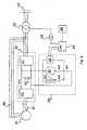
energy management arrangement 104 inFig.2 is coupled to the DC link 112 of thepower converter 102. Theenergy management arrangement 104 includes anenergy storage unit 121, apower dissipating resistor 122, a DC-to-DC voltage converter 123 and three switches labeled as SW1, SW2 and SW3. The switches SW1, SW2, SW3 can be operated in such a manner that the DC link 112 is connected to theenergy storage unit 121, theresistor 112, theconverter 123 or a combination thereof. TheUPS 105 is connected to theconverter 123 of theenergy management arrangement 104. - The operation of the wind turbine according to an embodiment will now be described with reference to the electrical system shown in
Fig.2 . During normal operation of the wind turbine, the electrical power generated by the generator is converted by thepower converter 102 into power having fixed frequency AC signals to be supplied to thepower grid 107. The switches SW1, SW2 and SW3 are open, and hence no power flows into theenergy management arrangement 104. A controller (not shown) constantly detects whether there is a power imbalance event which cause the power flow from the generator to the grid to be imbalanced. As mentioned earlier, the power imbalance event may be a voltage dip in the power grid 107 (low voltage or grid fault event), a converter fault (turbine fault event) or when there is a sudden wind gust causing a sudden increase in the rotational speed of the blades of the wind turbine (wind gust event). The grid fault event and turbine fault event may be collectively known as fault event. These events result in the electrical power generated by thegenerator 101 to be more than the power supplied to thepower grid 107, resulting in excess electrical power or energy. - Excess electrical power if not transferred to the grid or dissipated properly will lead to an increase in DC-link 112 voltage. In an induction generator, the current at the rotor also increases during power imbalance event. This is because during low voltage event, more active power is pumped from rotor circuit into the generator side converter. Therefore, the controller may detect a power imbalance event by determining whether the voltage at the DC link 112 increases above a predetermined threshold level. If the voltage at the DC link 112 is determined to be above the predetermined threshold level, a power imbalance event is detected. Alternatively or additionally, the controller may also determine a current level at the DC link 112 or at the input of the generator-
side converter 110. If the current level is above a predetermined threshold level, the power imbalance event is detected. - The controller may also sense the voltage at the output of
grid side converter 111 or at thepower grid 107 directly, for example, at the PCC (not shown) to thepower grid 107 to determine whether there is any voltage dip which results in the power imbalance event. It is also possible to determine whether a wind gust event has occurred by determining the wind speed or rotational speed of the rotor. Wind speed may be determined using wind anemometers commonly placed on top of the nacelle of the turbine. When the wind speed is determined to have increased substantially over a short period of time, a wind gust event is detected. - When the controller has detected the power imbalance event using any of the methods described above, it activates the
energy management arrangement 104. Theenergy management arrangement 104 can be activated by closing the switches SW1 and SW3. As a result, the excess electrical power generated is directed to theenergy management arrangement 104 and charges theenergy storage unit 121. In this embodiment, the voltage at the DC link 112 is able to charge theenergy storage unit 121 directly. If theenergy storage unit 121 operates at a different voltage from the DC link voltage, a DC-to-DC converter may be used to first convert the DC link voltage into a suitable DC voltage level suitable for charging theenergy storage unit 121. This arrangement is shown in the electrical system ofFig.3 . - When the
energy storage unit 121 is fully charged, the remaining excess electrical energy may be dissipated off in theresistor 122 as power loss. To activate thepower dissipating resistor 122, the controller closes the switch SW2 and opens SW3. During the power imbalance event, theUPS 105 may also be charged by the excess power from the DC link 112 or by the energy stored in theenergy storage unit 121 via theconverter 123. Additionally, theAC dump load 109 may also be activated to dissipate a part of the excess electrical power. - After the power imbalance event is over, the power stored in the
energy storage unit 121 may be used to supply active power to thepower grid 107. This is especially helpful when the power imbalance event is due to a low voltage event at thepower grid 107. The fast restoration of active power from theenergy storage unit 121 enables the turbine to help the grid to recover from the grid fault quickly and helps to meet grid compliance. Theenergy storage unit 121 may also continue to supply power to charge theUPS 105 after the power imbalance event by operating the switches SW1, SW2 and SW3. TheUPS 105 may be used to powerauxiliary components 106. The operation of the switches SW1, SW2 and SW3 during and after the power imbalance event is controlled by the controller. - It should be noted that the
generator 101 and thepower converter 102 are usually placed inside the nacelle of the turbine. Themain transformer 103, theenergy management arrangement 104 and/or theUPS 105 may also be placed inside the nacelle or outside the nacelle, for example in the tower or at the based of the turbine. Theauxiliary components 106 include lightings, fans, cooling units, power supplies, pumps etc, and may be arranged in any parts of the turbine. As mentioned earlier, theenergy storage unit 121 may be any types of energy storage system including but not limited to chemical, mechanical, electrical & electronics, hydraulic storage or their combinations. Some examples are ultra-capacitor banks, flow batteries, Metal-air batteries, NaS, Li-Ion, Ni-Cd, Lead Acid, Flywheel, CAES, SMES, fuel cell and pumped storages, or combination thereof. Fig.3 shows another electrical system of the wind turbine according to an embodiment. The electrical system inFig.3 is similar to that shown inFig.2 , except for the configuration of theenergy management arrangement 130. Theenergy management arrangement 130 inFig.3 also includes anenergy storage unit 131, apower dissipating resistor 132 and a DC-to-DC converter 133. In this embodiment, the DC-to-DC converter 133 is used to convert the DC voltage at the DC link 112 into a suitable DC voltage for charging theenergy storage unit 131 and theUPS 105.- During the power imbalance event, switch SW3 is closed and the voltage at the DC link 112 is converted by the DC-to-
DC converter 133 to the suitable DC voltage for charging theenergy storage unit 131. At the same time, the DC-to-DC converter 133 may also charge theUPS 105. When theenergy storage unit 131 is fully charged, the remaining electrical energy can be dissipated through theresistor 132. This is done by closing the switch SW2 and opening SW3. - Similarly when the power imbalance event is over, the energy stored in the
energy storage unit 131 may be used to supply active power to thepower grid 107. Theenergy storage unit 131 may also continue to supply power to charge theUPS 105 after the power imbalance event by operating the switches SW2 and SW3. TheUPS 105 may be used to powerauxiliary components 106. The operation of the switches SW2 and SW3 during and after the power imbalance event may be controlled by the controller (not shown). Fig.4 shows another electrical system of the wind turbine according to an embodiment. The electrical system inFig.4 is similar to that shown inFig.2 andFig.3 , except for the configuration of theenergy management arrangement 140 and the coupling of theenergy management arrangement 140 to thepower converter 102. In the electrical system inFig.4 , theenergy management arrangement 140 is coupled to the input of thepower converter 102. Specifically, theenergy management arrangement 140 is coupled to thestator windings 120 of thegenerator 101.- The electrical system in
Fig.4 includes an AC-to-DC converter 143 for converting the AC voltage at the input of thepower converter 102 into DC voltage as input to theenergy management arrangement 140. Theenergy management arrangement 140 inFig.4 includes anenergy storage unit 141, apower dissipating resistor 142, and switches SW4, SW5 and SW6. In this embodiment, DC voltage from the AC-to-DC converter 143 is used to charge theenergy storage unit 141 and theUPS 105. - During the power imbalance event, switch SW6 is closed and the AC signals at the input of the
power converter 102 are converted by the AC-to-DC converter 143 to DC voltage for charging theenergy storage unit 141. At the same time, the converted DC voltage may also charge theUPS 105 by closing switch SW4. When theenergy storage unit 141 is fully charged and there is still remaining excess electrical energy, the remaining excess energy is dissipated as power loss through thepower dissipating resistor 142. This is done by closing the switch SW5 and opening SW6. - When the power imbalance event is over, the energy stored in the
energy storage unit 141 may continue to supply power to charge theUPS 105 by operating the switches SW4, SW5 and SW6. TheUPS 105 may be used to powerauxiliary components 106. The operation of the switches SW4, SW5 and SW6 during and after the power imbalance event may be controlled by the controller (not shown). - In this embodiment, the DC voltage from the AC-to-
DC converter 143 is able to charge theenergy storage unit 141 and theUPS 105 directly. If theUPS 105 operates at a different voltage from the DC voltage from the AC-to-DC converter 143, a DC-to-DC converter may be used to convert the DC voltage from the AC-to-DC converter 143 into a suitable DC voltage level suitable for charging theUPS 105 in an alternative embodiment. Fig.5 shows another electrical system of the wind turbine according to an embodiment. In the electrical system inFig.5 , theenergy management arrangement 150 is coupled to the input of thepower converter 102. Specifically, theenergy management arrangement 150 is coupled to thestator windings 120 of thegenerator 101.- The
energy management arrangement 150 inFig.5 also includes anenergy storage unit 151, an AC-to-DC converter 153, a DC-to-AC converter 154, aDC link 155, aDC link capacitor 156, apower dissipating resistor 157 and switches SW7, SW7a and SW7b. In this embodiment, theenergy storage unit 151 may be a storage device which is charged using a fixed frequency AC voltage. An example of such a storage device includes a flywheel. A flywheel is a device having significant moment of inertia used for storing rotational energy. - The AC-to-
DC converter 153 converts the AC voltage at the input of thepower converter 102 into DC voltage, and the DC-to-AC converter 154 converts the DC voltage into AC voltage for charging theenergy storage unit 151. The DC voltage at the DC link 155 is also used to charge theUPS 105. - During the power imbalance event, switches SW7b and SW7 are closed and the AC voltage at the input of the
power converter 102 is converted by the AC-to-DC converter 153 and the DC-to-AC converter 154 into a fixed frequency AC voltage for charging theenergy storage unit 151. At the same time, the DC voltage at the DC link 155 may also charge theUPS 105. When theenergy storage unit 151 is fully charged, the remaining excess electrical energy may be dissipated off in theresistor 157 as power loss. To activate thepower dissipating resistor 157, the controller closes the switch SW7a and opens SW7. - When the power imbalance event is over, the energy stored in the
energy storage unit 151 may continue to supply power to charge theUPS 105 by closing the switches SW7. TheUPS 105 may be used to powerauxiliary components 106. The operation of the switches SW7, SW7a and SW7b during and after the power imbalance event may be controlled by the controller (not shown). Fig.6 shows an electrical system of the wind turbine using a doubly fed induction generator (DFIG) 201 according to an embodiment. The electrical system of the wind turbine inFig.6 includes theDFIG generator 201, apower converter 202, amain transformer 203, anenergy management arrangement 204, anUPS 205 and turbine auxiliary components represented byblock 206. Thepower converter 202 includes a generator-side converter 210 and a grid-side converter 211 connected via aDC link 212. The DC link 212 includes aDC link capacitor 213. Thepower converter 202, themain transformer 203, theenergy management arrangement 204, theUPS 205 and theauxiliary components 206 are similar to those already explained with reference toFig.1 , and will not be described here.- The
generator 201 includes bothstator windings 220 androtor windings 221. Thepower converter 202 is coupled to therotor windings 221 of thegenerator 201, and converts a portion of the electrical power generated by thegenerator 201 and supply to the grid. Thepower converter 202 also converts the electrical power from the generator at the rotor windings to a reactive power to maintain a desired power factor at the grid. Thestator windings 220 of thegenerator 201 are coupled to thepower grid 107 through themain transformer 203. In this arrangement, depending on the mode of operation of the turbine, power can flow from thepower grid 107 to therotor windings 221 to operate thegenerator 201, or power can flow from therotor windings 221 to thepower grid 107 to supplement power from thestator windings 220. - The
energy management arrangement 204 shown in Fig.66 is similar to theenergy management arrangement 104 described with reference toFig.2 . It is also possible to use theenergy management arrangement 130 described with reference toFig.3 in the electrical system shown inFig.6 in another embodiment. Theenergy management arrangement 204 is coupled to the DC link 212 of thepower converter 202. Theenergy management arrangement 204 includes anenergy storage unit 221, apower dissipating resistor 222, a DC-to-DC voltage converter 223 and three switches labeled as SW1', SW2' and SW3'. The functions of the components in theenergy management arrangement 204 are similar to that of theenergy management arrangement 104 inFig.2 , and will not be described here. TheUPS 205 is connected to thevoltage converter 223 of theenergy management arrangement 204. - During normal operation of the wind turbine at below synchronous speed, the electrical power generated by the generator is supplied to the
power grid 107 via thestator windings 220. The grid-side converter 211 converts the AC signals from the grid to DC signals. The generator-side converter 210 converts the DC signals on the DC link 212 into variable AC signals for thegenerator 201. The reverse sequence of signal flow in thepower converter 202 is also true for some signals. In the event that the wind turbine is operating at above synchronous speed, the electrical power generated by the generator is still supplied to thepower grid 107 via thestator windings 220 but the flow of power in thepower converter 202 is reversed. Power in therotor windings 221 now flows from the generator to thepower grid 107 via thepower converter 202, to supplement the power from thestator windings 220. - During a power imbalance event, excess electrical power or energy may be generated by the
generator 201. As mentioned earlier, the power imbalance event may be a voltage dip in the power grid 107 (low voltage event), a fault in the converter or when there is a sudden wind gust causing a sudden increase in the rotational speed of the blades of the wind turbine (wind gust event). According to the embodiment, a controller (not shown) detects the power imbalance event and activates theenergy management arrangement 204. - This excess electrical energy is converted by the generator-
side converter 210 into DC signals and placed on theDC link 212. Accordingly, the excess electrical energy charges the DC link 212, causing the DC link voltage to increase. Also in the event when there is a large voltage difference between thestator windings 220 and thepower grid 107, for example during a low voltage event, a large current is produced in the stator windings. This large current in thestator windings 220 induces high voltages in therotor windings 221 which also results in large currents being produced in therotor windings 221. The large currents in therotor windings 221 may damage the components in thepower converter 202. The high current in therotor windings 221 also charges up the DC link 212, resulting in the DC link voltage to increase. - Therefore, the controller may detect a power imbalance event by determining whether the voltage at the DC link 212 increases above a predetermined threshold level, or whether the current level at the DC link 212 or at the
rotor windings 221 is above a predetermined threshold level. If the voltage and/or current at the DC link 112 or the current at therotor windings 221 is determined to be above the predetermined threshold level, a power imbalance event is detected. As also mentioned earlier, the controller may also sense the voltage of thepower grid 107 to determine whether there is any voltage dip, determine the wind speed on the turbine blades using wind anemometer or determine the rotational speed of the rotor to detect any power imbalance event. - When the controller has detected the power imbalance event, it activates the
energy management arrangement 204 by controlling the switches SW1', SW2 and SW3'. The operation of theenergy management arrangement 204 has already been described with reference toFig.2 , and will not be repeated here. - It should be noted that the
energy management arrangement 204 may also be coupled to therotor windings 221 instead of the DC link 212 in another embodiment. In this embodiment, theenergy management arrangement 204 may have a similar configuration as theenergy management arrangement Fig.4 andFig.5 . Specifically, the electrical system inFig.6 then includes an AC-to-DC converter to convert the AC voltage at therotor windings 221 to suitable DC voltage to be operated by theenergy storage unit 221, theUPS 105 and thepower dissipating resistor 222. Fig.7 shows a flow-chart of a method for operating the wind turbine according to this embodiment. Step 300 includes detecting a power imbalance event. As mentioned earlier, examples of power imbalance events include a low voltage event and a wind gust event. The power imbalance event may be detected by determining the voltage at a power grid, the voltage at a DC link of a power converter, the current level at the input of the power converter, the rotational speed of the rotor or the wind speed on the turbine blades using wind anemometer.- Step 310 includes storing at least a portion of excess electrical energy generated when the power imbalance event is detected. As mentioned earlier, the excess power can be stored in an energy storage unit of an energy management arrangement. The energy management arrangement may be coupled to the DC link of the power converter, or to the input of the power converter to receive the excess power therefrom.
- It should be emphasized that the embodiments described above are possible examples of implementations which are merely set forth for a clear understanding of the principles of the invention. The person skilled in the art may make many variations and modifications to the embodiment(s) described above, said variations and modifications are intended to be included herein within the scope of the following claims.
Claims (13)
- A variable speed wind turbine (1) comprising:a generator (101);a power converter (102) for converting at least a portion of electrical power generated by the generator;an energy management arrangement (104; 140) coupled to the power converter, the energy management arrangement comprises an energy storage unit (121; 141); anda controller,wherein the controller is adapted to detect a power imbalance event and to transfer at least a portion of excess electrical energy generated by the generator to the energy storage unit to be stored therein when the power imbalance event is detected, andwherein the power imbalance event comprises a wind gust event,characterised in that the variable speed wind turbine further comprises an uninterrupted power supply UPS (105) coupled to the energy management arrangement, the UPS being adapted to receive electrical energy from the energy management arrangement to be stored therein.
- The variable speed wind turbine of claim 1, wherein the power converter comprises:a generator-side converter (110) adapted to convert an alternating current (AC) signal from the generator to a direct current (DC) signal;a grid-side converter (111) adapted to convert the DC signal to an AC signal; anda DC link (112) between the generator-side converter and the grid-side converter,wherein the energy management arrangement (104) is coupled to the DC link for receiving at least a portion of the excess electrical energy to be stored therein during the power imbalance event.
- The variable speed wind turbine of claim 2, wherein the energy management arrangement further comprises a DC-to-DC converter (123) for converting the DC signal at the DC link to a DC signal suitable to be processed by the energy storage unit.
- The variable speed wind turbine of claim 1, wherein the power converter comprises:a generator-side converter (110) adapted to convert an alternating current (AC) signal from the generator to a direct current (DC) signal;a grid-side converter (111) adapted to convert the DC signal to an AC signal; anda DC link (112) between the generator-side converter and the grid-side converter,wherein the energy management arrangement (140) is coupled to an input of the generator-side converter for receiving a portion of the excess electrical energy to be stored therein during the power imbalance event.
- The variable speed wind turbine of claim 4, wherein the energy management arrangement further comprises an AC-to-DC converter (143) for converting the AC signal at the input of the generator-side converter to a DC signal suitable to be processed by the energy storage unit.
- The variable speed wind turbine of claims 4 or 5, further comprising a second energy management arrangement, wherein the second energy management arrangement is coupled to the DC link for receiving a portion of the excess electrical energy to be stored therein during the power imbalance event.
- The variable speed wind turbine according to any of the preceding claims, wherein the energy management arrangement further comprises a power dissipating element (122; 142) for dissipating at least a portion of the excess electrical energy generated by the generator as power loss during the power imbalance event.
- The variable speed wind turbine of claim 7, wherein the power dissipating element comprises a resistor.
- The variable speed wind turbine of claims 7 or 8, wherein the power dissipating element is arranged in parallel to the energy storage unit.
- The variable speed wind turbine according to any of the preceding claims, wherein the energy management arrangement is adapted to supply electrical power to auxiliary components (106) in the wind turbine during the power imbalance event.
- A method for operating a variable speed wind turbine, comprising:detecting a power imbalance event;storing at least a portion of excess electrical energy generated by a generator (101) of the wind turbine in an energy management arrangement (104; 140) when the power imbalance event is detected,wherein the power imbalance event comprises a wind gust event,characterised in that the method further comprise transferring at least a portion of the excess electrical energy from the energy management arrangement to an uninterrupted power supply UPS (105) to be stored therein.
- The method of claim 11, further comprising dissipating at least a portion of the excess electrical energy generated by the generator as power loss through a power dissipating element (122; 142) in the energy management arrangement during the power imbalance event.
- The method of either of claims 11 or 12, further comprising supplying electrical power to auxiliary components (106) in the wind turbine by the energy management arrangement during the power imbalance event.
Applications Claiming Priority (3)
| Application Number | Priority Date | Filing Date | Title |
|---|---|---|---|
| DKPA200970084 | 2009-08-14 | ||
| US23689809P | 2009-08-26 | 2009-08-26 | |
| PCT/SG2010/000294WO2011019321A2 (en) | 2009-08-14 | 2010-08-10 | A variable speed wind turbine, and a method for operating the variable speed wind turbine during a power imbalance event |
Publications (2)
| Publication Number | Publication Date |
|---|---|
| EP2464860A2 EP2464860A2 (en) | 2012-06-20 |
| EP2464860B1true EP2464860B1 (en) | 2015-04-22 |
Family
ID=43586700
Family Applications (1)
| Application Number | Title | Priority Date | Filing Date |
|---|---|---|---|
| EP20100805664Not-in-forceEP2464860B1 (en) | 2009-08-14 | 2010-08-10 | A variable speed wind turbine, and a method for operating the variable speed wind turbine during a power imbalance event |
Country Status (4)
| Country | Link |
|---|---|
| US (1) | US9494138B2 (en) |
| EP (1) | EP2464860B1 (en) |
| ES (1) | ES2537126T3 (en) |
| WO (1) | WO2011019321A2 (en) |
Families Citing this family (49)
| Publication number | Priority date | Publication date | Assignee | Title |
|---|---|---|---|---|
| EP2166225B1 (en)* | 2008-09-19 | 2016-08-10 | Vestas Wind Systems A/S | A wind park having an auxiliary power supply |
| KR101599555B1 (en)* | 2009-12-24 | 2016-03-03 | 두산인프라코어 주식회사 | Power converter for hybrid |
| US20120074786A1 (en) | 2010-05-13 | 2012-03-29 | Eaton Corporation | Uninterruptible power supply systems and methods using isolated interface for variably available power source |
| CN103081273B (en)* | 2010-06-30 | 2016-05-11 | 维斯塔斯风力系统有限公司 | Wind turbine |
| US8994202B2 (en)* | 2010-12-10 | 2015-03-31 | Vestas Wind Systems A/S | Method and system for operating a wind turbine during an overvoltage event |
| US9509141B2 (en) | 2011-04-15 | 2016-11-29 | Siemens Aktiengesellschaft | Black start of wind turbine devices |
| EP2528184B1 (en)* | 2011-05-25 | 2014-09-10 | Siemens Aktiengesellschaft | Method and apparatus for controlling a DC-transmission link |
| US9690267B2 (en) | 2011-06-14 | 2017-06-27 | Vestas Wind Systems A/S | Selective droop response control for a wind turbine power plant |
| CA2844443C (en)* | 2011-07-20 | 2021-01-26 | Inventus Holdings, Llc | Dispatchable renewable energy generation, control and storage facility |
| US9325268B2 (en)* | 2011-07-27 | 2016-04-26 | Vestas Wind Systems A/S | Power dissipating arrangement in a wind turbine |
| EP2565443A1 (en) | 2011-09-05 | 2013-03-06 | XEMC Darwind B.V. | Generating auxiliary power for a wind turbine |
| US9416773B2 (en)* | 2012-04-04 | 2016-08-16 | Gamesa Innovation & Technology, S.L. | Power generation and distribution system for a wind turbine |
| CN102664422B (en)* | 2012-05-24 | 2014-03-26 | 电子科技大学 | Method for smoothing output power of wind power station by utilizing energy storage system |
| US8669669B1 (en)* | 2012-09-13 | 2014-03-11 | General Electric Company | Voltage control in a doubly-fed induction generator wind turbine system |
| DE102013001368A1 (en)* | 2013-01-28 | 2014-07-31 | Rwe Innogy Gmbh | ADVERTISING SYSTEM AND METHOD FOR OPERATING ANY WIND ENERGY SYSTEM |
| US9425726B2 (en)* | 2013-06-25 | 2016-08-23 | Masdar Institute Of Science And Technology | Fault-tolerant wind energy conversion system |
| ES2527972B1 (en)* | 2013-08-02 | 2015-11-20 | Gamesa Innovation & Technology, S.L. | Intelligent power management during a voltage drop in wind turbines |
| US8933572B1 (en) | 2013-09-04 | 2015-01-13 | King Fahd University Of Petroleum And Minerals | Adaptive superconductive magnetic energy storage (SMES) control method and system |
| US9513614B2 (en)* | 2013-09-11 | 2016-12-06 | General Electric Company | Auxiliary electric power system and method of regulating voltages of the same |
| EP3063851B1 (en)* | 2013-10-31 | 2021-12-22 | General Electric Company | System and method for controlling wind power generation systems |
| US9231509B2 (en) | 2013-11-25 | 2016-01-05 | General Electric Company | System and method for operating a power generation system within a power storage/discharge mode or a dynamic brake mode |
| WO2016055069A1 (en)* | 2014-10-07 | 2016-04-14 | Vestas Wind Systems A/S | Reactive power support from wind turbine facilities |
| US10050433B2 (en)* | 2014-12-11 | 2018-08-14 | General Electric Company | Power generation system and method with resistive braking capability |
| US9337762B1 (en)* | 2014-12-15 | 2016-05-10 | Eaton Corporation | System and method for magnetizing a transformer in an electrical system prior to energizing the electrical system |
| CN106160606B (en)* | 2015-03-24 | 2019-09-17 | 台达电子工业股份有限公司 | Wind power generation system and control method thereof |
| CN105140944A (en)* | 2015-09-02 | 2015-12-09 | 国网上海市电力公司 | Large wind electric field energy storage access system |
| EP3255776A1 (en)* | 2016-06-07 | 2017-12-13 | ABB Technology AG | A method and device for determination of a torsional deflection of a rotation shaft in the electromechanical drivetrain |
| US10205321B2 (en)* | 2016-08-05 | 2019-02-12 | Hamilton Sundstrand Corporation | Electrical accumulators for multilevel power systems |
| GB2553872B (en)* | 2016-09-19 | 2018-10-03 | Flexgen Power Systems Inc | Systems and methods for rapid activation of dispatchable power sources |
| US12362566B2 (en) | 2016-09-19 | 2025-07-15 | Flexgen Power Systems, Llc | Systems and methods for rapid activation and synchronization of dispatchable power sources |
| US10519933B2 (en)* | 2017-04-24 | 2019-12-31 | General Electric Company | Method of operating a wind turbine system including an energy storage system |
| US10491038B2 (en)* | 2017-06-15 | 2019-11-26 | General Electric Company | Electrical power subsystems and methods for controlling same |
| DE102018110245A1 (en)* | 2018-04-27 | 2019-10-31 | Universität Kassel | Method and circuit arrangement for controlling an asynchronous generator |
| EP3815210B1 (en) | 2018-06-26 | 2024-07-31 | Vestas Wind Systems A/S | Enhanced multi voltage dip ride through for renewable energy power plant with battery storage system |
| US10998760B2 (en)* | 2018-09-27 | 2021-05-04 | General Electric Company | System and method for controlling uninterruptible power supply of electrical power systems |
| WO2021083469A1 (en)* | 2019-10-31 | 2021-05-06 | Vestas Wind Systems A/S | A wind turbine with an overvoltage protection device |
| WO2021197607A1 (en)* | 2020-04-02 | 2021-10-07 | Abb Power Grids Switzerland Ag | Power supporting arrangement for a power grid |
| EP3975368A1 (en)* | 2020-09-25 | 2022-03-30 | Wobben Properties GmbH | Uninterruptible power supply for wind turbines |
| CN114649823A (en)* | 2020-12-17 | 2022-06-21 | 北京金风科创风电设备有限公司 | Black start device and method of wind generating set and wind generating set |
| EP4108910A1 (en) | 2021-06-24 | 2022-12-28 | Siemens Gamesa Renewable Energy A/S | Wind turbine power plant including auxiliary systems |
| US20240421663A1 (en)* | 2021-09-24 | 2024-12-19 | University Of Virginia Patent Foundation | Super-rated operation for increased wind turbine power with energy storage |
| JP2025506565A (en) | 2022-02-08 | 2025-03-11 | フラワー ターバインズ インコーポレイテッド | Systems and methods for operating a group of fluid turbines - Patents.com |
| WO2023201214A2 (en)* | 2022-04-12 | 2023-10-19 | Mark Daniel Farb | Systems and methods for operating a cluster of fluid turbines |
| AU2023253688A1 (en) | 2022-04-12 | 2024-10-31 | Mark Daniel Farb | Systems and methods for operating a cluster of fluid turbines |
| WO2024050317A1 (en) | 2022-08-28 | 2024-03-07 | Flower Turbines, Inc. | Systems and methods for operating a cluster of fluid turbines |
| US12316197B2 (en)* | 2022-08-31 | 2025-05-27 | Sapphire Technologies, Inc. | Brake resistor design for controlling rotor speed during generator shutdown sequence |
| CN119895139A (en) | 2022-09-18 | 2025-04-25 | 花卉涡轮机股份有限公司 | Sleeve for turbine shaft |
| WO2024151908A2 (en) | 2023-01-15 | 2024-07-18 | Mark Daniel Farb | Systems and methods for fluid turbine operations |
| US12362698B2 (en) | 2023-04-09 | 2025-07-15 | Flower Turbines, Inc. | Green sun-shaded charging stations |
Family Cites Families (21)
| Publication number | Priority date | Publication date | Assignee | Title |
|---|---|---|---|---|
| US6134127A (en)* | 1994-05-18 | 2000-10-17 | Hamilton Sunstrand Corporation | PWM harmonic control |
| ATE440315T1 (en)* | 2001-09-28 | 2009-09-15 | Vestas Wind Sys As | METHOD AND COMPUTER SYSTEM FOR PROCESSING OPERATING DATA OF WIND TURBINE SYSTEMS |
| US6858953B2 (en) | 2002-12-20 | 2005-02-22 | Hawaiian Electric Company, Inc. | Power control interface between a wind farm and a power transmission system |
| US6921985B2 (en) | 2003-01-24 | 2005-07-26 | General Electric Company | Low voltage ride through for wind turbine generators |
| WO2004098261A2 (en) | 2003-05-02 | 2004-11-18 | Xantrex Technology Inc. | Control system for doubly fed induction generator |
| PT1651865E (en)* | 2003-08-07 | 2007-01-31 | Vestas Wind Sys As | Method of controlling a wind turbine connected to an electric utility grid during malfunction in said electric utility grid, control system, wind turbine and family hereof |
| JP3918837B2 (en)* | 2004-08-06 | 2007-05-23 | 株式会社日立製作所 | Wind power generator |
| ES2901709T3 (en)* | 2005-09-27 | 2022-03-23 | Siemens Gamesa Renewable Energy Innovation & Technology SL | Inverter system and method of operation thereof |
| US7233079B1 (en)* | 2005-10-18 | 2007-06-19 | Willard Cooper | Renewable energy electric power generating system |
| US7433216B2 (en)* | 2005-11-14 | 2008-10-07 | Hamilton Sundstrand Corporation | Voltage control and harmonic minimization of multi-level converter |
| KR100668118B1 (en)* | 2005-12-30 | 2007-01-16 | 한국전기연구원 | Power converter and power conversion method for winding type induction generator control |
| US7276807B2 (en)* | 2006-01-19 | 2007-10-02 | General Electric Company | Wind turbine dump load system and method |
| WO2007140466A2 (en)* | 2006-05-31 | 2007-12-06 | Wisconsin Alumni Research Foundation | Power conditioning architecture for a wind turbine |
| US7391126B2 (en)* | 2006-06-30 | 2008-06-24 | General Electric Company | Systems and methods for an integrated electrical sub-system powered by wind energy |
| DE102007035570A1 (en)* | 2007-07-26 | 2009-02-05 | Universität Kassel | Double-fed asynchronous generator and method of operation |
| US8004866B2 (en)* | 2008-01-03 | 2011-08-23 | Teknic, Inc. | Method and apparatus to remove energy from DC loads |
| ES2776948T3 (en)* | 2009-06-30 | 2020-08-03 | Vestas Wind Sys As | Wind turbine with control means for power management during faults in the distribution network |
| US8310074B2 (en)* | 2009-10-30 | 2012-11-13 | General Electric Company | Method and apparatus for generating power in a wind turbine |
| US8022565B2 (en)* | 2009-11-13 | 2011-09-20 | General Electric Company | Method and apparatus for controlling a wind turbine |
| US8093741B2 (en)* | 2010-10-29 | 2012-01-10 | General Electric Company | Method and system for providing increased turbine output for doubly fed induction generator |
| US8076789B2 (en)* | 2010-12-21 | 2011-12-13 | General Electric Company | System and method for controlling wind turbine power output |
- 2010
- 2010-08-10EPEP20100805664patent/EP2464860B1/ennot_activeNot-in-force
- 2010-08-10ESES10805664.9Tpatent/ES2537126T3/enactiveActive
- 2010-08-10WOPCT/SG2010/000294patent/WO2011019321A2/enactiveApplication Filing
- 2010-08-10USUS13/390,174patent/US9494138B2/ennot_activeExpired - Fee Related
Also Published As
| Publication number | Publication date |
|---|---|
| EP2464860A2 (en) | 2012-06-20 |
| US20120217824A1 (en) | 2012-08-30 |
| WO2011019321A3 (en) | 2011-08-18 |
| WO2011019321A2 (en) | 2011-02-17 |
| US9494138B2 (en) | 2016-11-15 |
| ES2537126T3 (en) | 2015-06-02 |
Similar Documents
| Publication | Publication Date | Title |
|---|---|---|
| EP2464860B1 (en) | A variable speed wind turbine, and a method for operating the variable speed wind turbine during a power imbalance event | |
| Daoud et al. | A flywheel energy storage system for fault ride through support of grid-connected VSC HVDC-based offshore wind farms | |
| EP2306001B1 (en) | Multi-use energy storage for renewable sources | |
| Chen et al. | A review of the state of the art of power electronics for wind turbines | |
| US10243352B2 (en) | Battery-supported braking system for a wind turbine | |
| JP5785243B2 (en) | Wind turbine with high temperature superconducting multiphase generator | |
| EP2360375B1 (en) | Method for operating a power dissipating unit in a wind turbine | |
| EP2573895B1 (en) | Method for operating a wind farm, wind farm controller and wind farm | |
| US20110142634A1 (en) | Overspeed protection system and method | |
| US20150001931A1 (en) | Methods of controlling a combined plant including at least one generator and an energy store | |
| EP2896101B1 (en) | Power plant control during a low voltage or a high voltage event | |
| US20120056425A1 (en) | Stand alone operation system for use with utility grade synchronous wind turbine generators | |
| DK1852605T3 (en) | Angular control of wind turbine blades in a wind turbine in an emergency | |
| Mendis et al. | Remote area power supply system: an integrated control approach based on active power balance | |
| KR101687900B1 (en) | A method for smoothing wind power fluctuation based on battery energy storage system for wind farm | |
| CN110785906B (en) | Method and system for increasing electric power generated by a power generation system | |
| Stavrakakis | 2.10 Electrical Parts of Wind Turbines | |
| WO2011160643A2 (en) | A wind turbine and a method of operating a wind turbine | |
| CN116221022A (en) | Method for operating a wind farm and wind farm | |
| EP4084318A1 (en) | A wind power facility and method | |
| Zhang et al. | Wind turbine control design to enhance the fault ride-through capability | |
| Shen et al. | Advanced control of DFIG to enhance the transient voltage support capability | |
| EP4191055A1 (en) | A method for operating a wind farm and a wind farm | |
| WO2025131277A1 (en) | Methods for operating wind turbines and wind turbines | |
| CN115882495A (en) | Wind turbines and transmission systems |
Legal Events
| Date | Code | Title | Description |
|---|---|---|---|
| PUAI | Public reference made under article 153(3) epc to a published international application that has entered the european phase | Free format text:ORIGINAL CODE: 0009012 | |
| 17P | Request for examination filed | Effective date:20120309 | |
| AK | Designated contracting states | Kind code of ref document:A2 Designated state(s):AL AT BE BG CH CY CZ DE DK EE ES FI FR GB GR HR HU IE IS IT LI LT LU LV MC MK MT NL NO PL PT RO SE SI SK SM TR | |
| DAX | Request for extension of the european patent (deleted) | ||
| 17Q | First examination report despatched | Effective date:20131212 | |
| REG | Reference to a national code | Ref country code:DE Ref legal event code:R079 Ref document number:602010024197 Country of ref document:DE Free format text:PREVIOUS MAIN CLASS: F03D0007000000 Ipc:F03D0009020000 | |
| RIC1 | Information provided on ipc code assigned before grant | Ipc:F03D 9/02 20060101AFI20141205BHEP Ipc:F03D 7/02 20060101ALI20141205BHEP | |
| GRAP | Despatch of communication of intention to grant a patent | Free format text:ORIGINAL CODE: EPIDOSNIGR1 | |
| INTG | Intention to grant announced | Effective date:20150129 | |
| GRAS | Grant fee paid | Free format text:ORIGINAL CODE: EPIDOSNIGR3 | |
| GRAA | (expected) grant | Free format text:ORIGINAL CODE: 0009210 | |
| AK | Designated contracting states | Kind code of ref document:B1 Designated state(s):AL AT BE BG CH CY CZ DE DK EE ES FI FR GB GR HR HU IE IS IT LI LT LU LV MC MK MT NL NO PL PT RO SE SI SK SM TR | |
| REG | Reference to a national code | Ref country code:GB Ref legal event code:FG4D | |
| REG | Reference to a national code | Ref country code:CH Ref legal event code:EP | |
| REG | Reference to a national code | Ref country code:AT Ref legal event code:REF Ref document number:723402 Country of ref document:AT Kind code of ref document:T Effective date:20150515 Ref country code:CH Ref legal event code:PCOW Free format text:NEW ADDRESS: HEDEAGER 42, 8200 AARHUS N (DK) | |
| REG | Reference to a national code | Ref country code:IE Ref legal event code:FG4D | |
| REG | Reference to a national code | Ref country code:ES Ref legal event code:FG2A Ref document number:2537126 Country of ref document:ES Kind code of ref document:T3 Effective date:20150602 | |
| RAP2 | Party data changed (patent owner data changed or rights of a patent transferred) | Owner name:VESTAS WIND SYSTEMS A/S | |
| REG | Reference to a national code | Ref country code:DE Ref legal event code:R096 Ref document number:602010024197 Country of ref document:DE Effective date:20150603 | |
| REG | Reference to a national code | Ref country code:NL Ref legal event code:VDEP Effective date:20150422 | |
| REG | Reference to a national code | Ref country code:AT Ref legal event code:MK05 Ref document number:723402 Country of ref document:AT Kind code of ref document:T Effective date:20150422 | |
| REG | Reference to a national code | Ref country code:LT Ref legal event code:MG4D | |
| PG25 | Lapsed in a contracting state [announced via postgrant information from national office to epo] | Ref country code:NL Free format text:LAPSE BECAUSE OF FAILURE TO SUBMIT A TRANSLATION OF THE DESCRIPTION OR TO PAY THE FEE WITHIN THE PRESCRIBED TIME-LIMIT Effective date:20150422 | |
| PG25 | Lapsed in a contracting state [announced via postgrant information from national office to epo] | Ref country code:FI Free format text:LAPSE BECAUSE OF FAILURE TO SUBMIT A TRANSLATION OF THE DESCRIPTION OR TO PAY THE FEE WITHIN THE PRESCRIBED TIME-LIMIT Effective date:20150422 Ref country code:LT Free format text:LAPSE BECAUSE OF FAILURE TO SUBMIT A TRANSLATION OF THE DESCRIPTION OR TO PAY THE FEE WITHIN THE PRESCRIBED TIME-LIMIT Effective date:20150422 Ref country code:HR Free format text:LAPSE BECAUSE OF FAILURE TO SUBMIT A TRANSLATION OF THE DESCRIPTION OR TO PAY THE FEE WITHIN THE PRESCRIBED TIME-LIMIT Effective date:20150422 Ref country code:NO Free format text:LAPSE BECAUSE OF FAILURE TO SUBMIT A TRANSLATION OF THE DESCRIPTION OR TO PAY THE FEE WITHIN THE PRESCRIBED TIME-LIMIT Effective date:20150722 Ref country code:PT Free format text:LAPSE BECAUSE OF FAILURE TO SUBMIT A TRANSLATION OF THE DESCRIPTION OR TO PAY THE FEE WITHIN THE PRESCRIBED TIME-LIMIT Effective date:20150824 | |
| PG25 | Lapsed in a contracting state [announced via postgrant information from national office to epo] | Ref country code:AT Free format text:LAPSE BECAUSE OF FAILURE TO SUBMIT A TRANSLATION OF THE DESCRIPTION OR TO PAY THE FEE WITHIN THE PRESCRIBED TIME-LIMIT Effective date:20150422 Ref country code:GR Free format text:LAPSE BECAUSE OF FAILURE TO SUBMIT A TRANSLATION OF THE DESCRIPTION OR TO PAY THE FEE WITHIN THE PRESCRIBED TIME-LIMIT Effective date:20150723 Ref country code:LV Free format text:LAPSE BECAUSE OF FAILURE TO SUBMIT A TRANSLATION OF THE DESCRIPTION OR TO PAY THE FEE WITHIN THE PRESCRIBED TIME-LIMIT Effective date:20150422 Ref country code:IS Free format text:LAPSE BECAUSE OF FAILURE TO SUBMIT A TRANSLATION OF THE DESCRIPTION OR TO PAY THE FEE WITHIN THE PRESCRIBED TIME-LIMIT Effective date:20150822 | |
| REG | Reference to a national code | Ref country code:DE Ref legal event code:R097 Ref document number:602010024197 Country of ref document:DE | |
| PG25 | Lapsed in a contracting state [announced via postgrant information from national office to epo] | Ref country code:EE Free format text:LAPSE BECAUSE OF FAILURE TO SUBMIT A TRANSLATION OF THE DESCRIPTION OR TO PAY THE FEE WITHIN THE PRESCRIBED TIME-LIMIT Effective date:20150422 Ref country code:DK Free format text:LAPSE BECAUSE OF FAILURE TO SUBMIT A TRANSLATION OF THE DESCRIPTION OR TO PAY THE FEE WITHIN THE PRESCRIBED TIME-LIMIT Effective date:20150422 | |
| PLBE | No opposition filed within time limit | Free format text:ORIGINAL CODE: 0009261 | |
| STAA | Information on the status of an ep patent application or granted ep patent | Free format text:STATUS: NO OPPOSITION FILED WITHIN TIME LIMIT | |
| PG25 | Lapsed in a contracting state [announced via postgrant information from national office to epo] | Ref country code:CZ Free format text:LAPSE BECAUSE OF FAILURE TO SUBMIT A TRANSLATION OF THE DESCRIPTION OR TO PAY THE FEE WITHIN THE PRESCRIBED TIME-LIMIT Effective date:20150422 Ref country code:SK Free format text:LAPSE BECAUSE OF FAILURE TO SUBMIT A TRANSLATION OF THE DESCRIPTION OR TO PAY THE FEE WITHIN THE PRESCRIBED TIME-LIMIT Effective date:20150422 Ref country code:RO Free format text:LAPSE BECAUSE OF NON-PAYMENT OF DUE FEES Effective date:20150422 Ref country code:PL Free format text:LAPSE BECAUSE OF FAILURE TO SUBMIT A TRANSLATION OF THE DESCRIPTION OR TO PAY THE FEE WITHIN THE PRESCRIBED TIME-LIMIT Effective date:20150422 | |
| 26N | No opposition filed | Effective date:20160125 | |
| PG25 | Lapsed in a contracting state [announced via postgrant information from national office to epo] | Ref country code:MC Free format text:LAPSE BECAUSE OF FAILURE TO SUBMIT A TRANSLATION OF THE DESCRIPTION OR TO PAY THE FEE WITHIN THE PRESCRIBED TIME-LIMIT Effective date:20150422 Ref country code:LU Free format text:LAPSE BECAUSE OF FAILURE TO SUBMIT A TRANSLATION OF THE DESCRIPTION OR TO PAY THE FEE WITHIN THE PRESCRIBED TIME-LIMIT Effective date:20150810 | |
| REG | Reference to a national code | Ref country code:CH Ref legal event code:PL | |
| PG25 | Lapsed in a contracting state [announced via postgrant information from national office to epo] | Ref country code:IT Free format text:LAPSE BECAUSE OF FAILURE TO SUBMIT A TRANSLATION OF THE DESCRIPTION OR TO PAY THE FEE WITHIN THE PRESCRIBED TIME-LIMIT Effective date:20150422 Ref country code:LI Free format text:LAPSE BECAUSE OF NON-PAYMENT OF DUE FEES Effective date:20150831 Ref country code:CH Free format text:LAPSE BECAUSE OF NON-PAYMENT OF DUE FEES Effective date:20150831 | |
| PG25 | Lapsed in a contracting state [announced via postgrant information from national office to epo] | Ref country code:SI Free format text:LAPSE BECAUSE OF FAILURE TO SUBMIT A TRANSLATION OF THE DESCRIPTION OR TO PAY THE FEE WITHIN THE PRESCRIBED TIME-LIMIT Effective date:20150422 | |
| REG | Reference to a national code | Ref country code:IE Ref legal event code:MM4A | |
| PG25 | Lapsed in a contracting state [announced via postgrant information from national office to epo] | Ref country code:IE Free format text:LAPSE BECAUSE OF NON-PAYMENT OF DUE FEES Effective date:20150810 | |
| PG25 | Lapsed in a contracting state [announced via postgrant information from national office to epo] | Ref country code:BE Free format text:LAPSE BECAUSE OF FAILURE TO SUBMIT A TRANSLATION OF THE DESCRIPTION OR TO PAY THE FEE WITHIN THE PRESCRIBED TIME-LIMIT Effective date:20150422 | |
| REG | Reference to a national code | Ref country code:FR Ref legal event code:PLFP Year of fee payment:7 | |
| PG25 | Lapsed in a contracting state [announced via postgrant information from national office to epo] | Ref country code:MT Free format text:LAPSE BECAUSE OF FAILURE TO SUBMIT A TRANSLATION OF THE DESCRIPTION OR TO PAY THE FEE WITHIN THE PRESCRIBED TIME-LIMIT Effective date:20150422 | |
| PG25 | Lapsed in a contracting state [announced via postgrant information from national office to epo] | Ref country code:SM Free format text:LAPSE BECAUSE OF FAILURE TO SUBMIT A TRANSLATION OF THE DESCRIPTION OR TO PAY THE FEE WITHIN THE PRESCRIBED TIME-LIMIT Effective date:20150422 Ref country code:BG Free format text:LAPSE BECAUSE OF FAILURE TO SUBMIT A TRANSLATION OF THE DESCRIPTION OR TO PAY THE FEE WITHIN THE PRESCRIBED TIME-LIMIT Effective date:20150422 Ref country code:HU Free format text:LAPSE BECAUSE OF FAILURE TO SUBMIT A TRANSLATION OF THE DESCRIPTION OR TO PAY THE FEE WITHIN THE PRESCRIBED TIME-LIMIT; INVALID AB INITIO Effective date:20100810 | |
| PG25 | Lapsed in a contracting state [announced via postgrant information from national office to epo] | Ref country code:CY Free format text:LAPSE BECAUSE OF FAILURE TO SUBMIT A TRANSLATION OF THE DESCRIPTION OR TO PAY THE FEE WITHIN THE PRESCRIBED TIME-LIMIT Effective date:20150422 Ref country code:SE Free format text:LAPSE BECAUSE OF FAILURE TO SUBMIT A TRANSLATION OF THE DESCRIPTION OR TO PAY THE FEE WITHIN THE PRESCRIBED TIME-LIMIT Effective date:20150422 | |
| REG | Reference to a national code | Ref country code:FR Ref legal event code:PLFP Year of fee payment:8 | |
| PG25 | Lapsed in a contracting state [announced via postgrant information from national office to epo] | Ref country code:TR Free format text:LAPSE BECAUSE OF FAILURE TO SUBMIT A TRANSLATION OF THE DESCRIPTION OR TO PAY THE FEE WITHIN THE PRESCRIBED TIME-LIMIT Effective date:20150422 | |
| PG25 | Lapsed in a contracting state [announced via postgrant information from national office to epo] | Ref country code:MK Free format text:LAPSE BECAUSE OF FAILURE TO SUBMIT A TRANSLATION OF THE DESCRIPTION OR TO PAY THE FEE WITHIN THE PRESCRIBED TIME-LIMIT Effective date:20150422 | |
| REG | Reference to a national code | Ref country code:FR Ref legal event code:PLFP Year of fee payment:9 | |
| PG25 | Lapsed in a contracting state [announced via postgrant information from national office to epo] | Ref country code:AL Free format text:LAPSE BECAUSE OF FAILURE TO SUBMIT A TRANSLATION OF THE DESCRIPTION OR TO PAY THE FEE WITHIN THE PRESCRIBED TIME-LIMIT Effective date:20150422 | |
| PGFP | Annual fee paid to national office [announced via postgrant information from national office to epo] | Ref country code:GB Payment date:20230822 Year of fee payment:14 Ref country code:ES Payment date:20230914 Year of fee payment:14 | |
| PGFP | Annual fee paid to national office [announced via postgrant information from national office to epo] | Ref country code:FR Payment date:20230824 Year of fee payment:14 Ref country code:DE Payment date:20230828 Year of fee payment:14 | |
| REG | Reference to a national code | Ref country code:DE Ref legal event code:R119 Ref document number:602010024197 Country of ref document:DE | |
| GBPC | Gb: european patent ceased through non-payment of renewal fee | Effective date:20240810 | |
| PG25 | Lapsed in a contracting state [announced via postgrant information from national office to epo] | Ref country code:DE Free format text:LAPSE BECAUSE OF NON-PAYMENT OF DUE FEES Effective date:20250301 | |
| PG25 | Lapsed in a contracting state [announced via postgrant information from national office to epo] | Ref country code:GB Free format text:LAPSE BECAUSE OF NON-PAYMENT OF DUE FEES Effective date:20240810 | |
| PG25 | Lapsed in a contracting state [announced via postgrant information from national office to epo] | Ref country code:FR Free format text:LAPSE BECAUSE OF NON-PAYMENT OF DUE FEES Effective date:20240831 | |
| REG | Reference to a national code | Ref country code:ES Ref legal event code:FD2A Effective date:20250926 | |
| PG25 | Lapsed in a contracting state [announced via postgrant information from national office to epo] | Ref country code:ES Free format text:LAPSE BECAUSE OF NON-PAYMENT OF DUE FEES Effective date:20240811 |