EP2462889A1 - Bone anchoring device - Google Patents
Bone anchoring deviceDownload PDFInfo
- Publication number
- EP2462889A1 EP2462889A1EP10194787AEP10194787AEP2462889A1EP 2462889 A1EP2462889 A1EP 2462889A1EP 10194787 AEP10194787 AEP 10194787AEP 10194787 AEP10194787 AEP 10194787AEP 2462889 A1EP2462889 A1EP 2462889A1
- Authority
- EP
- European Patent Office
- Prior art keywords
- bone anchoring
- seat member
- anchoring device
- seat
- pressure member
- Prior art date
- Legal status (The legal status is an assumption and is not a legal conclusion. Google has not performed a legal analysis and makes no representation as to the accuracy of the status listed.)
- Granted
Links
Images


Classifications
- A—HUMAN NECESSITIES
- A61—MEDICAL OR VETERINARY SCIENCE; HYGIENE
- A61B—DIAGNOSIS; SURGERY; IDENTIFICATION
- A61B17/00—Surgical instruments, devices or methods
- A61B17/56—Surgical instruments or methods for treatment of bones or joints; Devices specially adapted therefor
- A61B17/58—Surgical instruments or methods for treatment of bones or joints; Devices specially adapted therefor for osteosynthesis, e.g. bone plates, screws or setting implements
- A61B17/68—Internal fixation devices, including fasteners and spinal fixators, even if a part thereof projects from the skin
- A61B17/70—Spinal positioners or stabilisers, e.g. stabilisers comprising fluid filler in an implant
- A61B17/7001—Screws or hooks combined with longitudinal elements which do not contact vertebrae
- A61B17/7035—Screws or hooks, wherein a rod-clamping part and a bone-anchoring part can pivot relative to each other
- A61B17/7037—Screws or hooks, wherein a rod-clamping part and a bone-anchoring part can pivot relative to each other wherein pivoting is blocked when the rod is clamped
- A—HUMAN NECESSITIES
- A61—MEDICAL OR VETERINARY SCIENCE; HYGIENE
- A61B—DIAGNOSIS; SURGERY; IDENTIFICATION
- A61B17/00—Surgical instruments, devices or methods
- A61B17/56—Surgical instruments or methods for treatment of bones or joints; Devices specially adapted therefor
- A61B17/58—Surgical instruments or methods for treatment of bones or joints; Devices specially adapted therefor for osteosynthesis, e.g. bone plates, screws or setting implements
- A61B17/68—Internal fixation devices, including fasteners and spinal fixators, even if a part thereof projects from the skin
- A61B17/70—Spinal positioners or stabilisers, e.g. stabilisers comprising fluid filler in an implant
- A61B17/7001—Screws or hooks combined with longitudinal elements which do not contact vertebrae
- A61B17/7032—Screws or hooks with U-shaped head or back through which longitudinal rods pass
- A—HUMAN NECESSITIES
- A61—MEDICAL OR VETERINARY SCIENCE; HYGIENE
- A61B—DIAGNOSIS; SURGERY; IDENTIFICATION
- A61B17/00—Surgical instruments, devices or methods
- A61B17/56—Surgical instruments or methods for treatment of bones or joints; Devices specially adapted therefor
- A61B17/58—Surgical instruments or methods for treatment of bones or joints; Devices specially adapted therefor for osteosynthesis, e.g. bone plates, screws or setting implements
- A61B17/68—Internal fixation devices, including fasteners and spinal fixators, even if a part thereof projects from the skin
- A61B17/70—Spinal positioners or stabilisers, e.g. stabilisers comprising fluid filler in an implant
- A61B17/7001—Screws or hooks combined with longitudinal elements which do not contact vertebrae
- A61B17/7035—Screws or hooks, wherein a rod-clamping part and a bone-anchoring part can pivot relative to each other
- A61B17/7038—Screws or hooks, wherein a rod-clamping part and a bone-anchoring part can pivot relative to each other to a different extent in different directions, e.g. within one plane only
- A—HUMAN NECESSITIES
- A61—MEDICAL OR VETERINARY SCIENCE; HYGIENE
- A61B—DIAGNOSIS; SURGERY; IDENTIFICATION
- A61B17/00—Surgical instruments, devices or methods
- A61B17/56—Surgical instruments or methods for treatment of bones or joints; Devices specially adapted therefor
- A61B17/58—Surgical instruments or methods for treatment of bones or joints; Devices specially adapted therefor for osteosynthesis, e.g. bone plates, screws or setting implements
- A61B17/68—Internal fixation devices, including fasteners and spinal fixators, even if a part thereof projects from the skin
- A61B17/84—Fasteners therefor or fasteners being internal fixation devices
- A61B17/86—Pins or screws or threaded wires; nuts therefor
- A61B17/8605—Heads, i.e. proximal ends projecting from bone
- Y—GENERAL TAGGING OF NEW TECHNOLOGICAL DEVELOPMENTS; GENERAL TAGGING OF CROSS-SECTIONAL TECHNOLOGIES SPANNING OVER SEVERAL SECTIONS OF THE IPC; TECHNICAL SUBJECTS COVERED BY FORMER USPC CROSS-REFERENCE ART COLLECTIONS [XRACs] AND DIGESTS
- Y10—TECHNICAL SUBJECTS COVERED BY FORMER USPC
- Y10T—TECHNICAL SUBJECTS COVERED BY FORMER US CLASSIFICATION
- Y10T29/00—Metal working
- Y10T29/49—Method of mechanical manufacture
- Y10T29/49826—Assembling or joining
Definitions
- the inventionrelates to a bone anchoring device, which comprises a bone anchoring element for anchoring in a bone or a vertebra, a receiving part for coupling the bone anchoring element to a stabilization element such as a spinal rod, wherein the bone anchoring element is pivotable in the receiving part and can be pivoted to at least one side with an enlarged pivot angle.
- a bone anchoring device of this typeis described in US 6,736,820 .
- the bone anchoring devicecomprises a bone screw and a receiving part with an open first bore and a substantially U-shaped cross-section for receiving the rod and a second bore on the end opposite to the first bore and a seat for the head.
- the edge bounding the free end of the second boreis of asymmetric construction.
- an insert pieceis provided, which has a spherical bottom as the seat for the head. This allows to change the orientation of the enlarged pivot angle.
- US 2005/0154391 A1describes a bone anchor assembly with a bone anchor and a receiving member.
- the receiving memberhas a first section having a first bore defining a first bore axis and a second section having a second bore defining a second bore axis and being sized to receive at least a portion of the bone anchor, wherein the second bore axis intersects the first bore axis.
- the second sectionis rotatable about the first bore axis. In an embodiment, the second section is seated internally within the first section.
- the second sectionis rotatable with respect to the first section, it is possible to pivot bone anchors out of alignment with one another to avoid interference due to the close proximity of adjacent vertebrae.
- a locking elementis provided, which is shaped and configured to allow an anchoring member such as a screw or a hook to polyaxially rotate at large angles about a central axis of the bone anchor before compression locking the anchoring member within an anchor head.
- the bone anchoring deviceallows to rotate the seat member that holds the head of the screw by means of a driver inserted from the top end of the receiving part so that the direction of pivoting can be adjusted to any desired direction.
- the orientation of the driverfor example, the orientation of a handle of the driver, can be used as a precise indication of the orientation of the seat member. Hence, it is possible to adjust the direction of an enlarged pivot angle during surgery.
- the locking of the head in the seat memberis effected by pressure exerted from above onto the head, which is then pressed against the seat. Therefore, the locking of the head is effected in a safe and predictable manner.
- a bone anchoring devicecomprises a bone anchoring element 1 in the form of a bone screw having a threaded shaft 2 and a head 3.
- the head 3is typically spherically-shaped and has a recess 3 a for engagement with a driver.
- the head 3is held in a receiving part 4 that couples the bone anchoring element 1 to a stabilization rod 100.
- a seat member 5providing a seat for the head 3 of the bone anchoring element 1, a first pressure member 6 and a second pressure member 7 for exerting pressure onto the head 3 of the bone anchoring element are arranged.
- a fixation element in the form of a fixation screw 8is provided for securing and fixing the rod 100 in the receiving part 4.
- the receiving part 4will be described with reference to Figs. 1 to 4 . It has a top end 4a and a bottom end 4b, a central axis C and a coaxial bore 9 extending from the top end 4a to the bottom end 4b. Adjacent to the top end 4a a substantially U-shaped recess 10 is provided, which forms a channel for receiving the rod 100. By means of the recess 10 two free legs 11a, 11b are formed, which are provided with an internal thread 12 cooperating with the fixation screw 8. At the lower portion of the bore 9 near the bottom end 4b a stop 13 in the form of an annular edge is provided for preventing the seat member 5 from escaping through the opening 14 at the bottom end 4b. It shall be noted that the bore 9 is not restricted to the specific shape of the bore showing in the drawings but can have different portions with different diameters.
- the seat member 5is shown in particular in Figs. 5 to 7 . It comprises a hollow cylindrical first portion 15, the inner diameter of which is slightly larger than the maximum diameter of the spherically-shaped head 3 and the outer diameter, of which is slightly smaller than the inner diameter of the bore 9, so that the seat member 5 insertable into the bore 9.
- the axial length of the first portion 15is such that when the head 3 rests within the seat portion 16, the first portion 15 projects above the head 3.
- the seat member 5comprises a hollow second portion 16, which has an internal spherically-shaped surface 16a for providing a seat for the spherically-shaped head 3.
- the outer surface 16b of the second portion 16is also spherically-shaped with an outer diameter that is smaller than the outer diameter of the first hollow cylindrical portion 15.
- the second portion 16is asymmetric with respect to a plane including the cylinder axis Z. This is achieved in that the lower edge 16c is inclined with respect to the hollow cylindrical first portion 15 at an angle ⁇ .
- the screw element 1can pivot when it is seated in the seat 16a at a greater angle to one side relative to the cylinder axis Z compared to the opposite side.
- the member 5can be sized such that the pivot angle of the screw element with respect to the one side can be only as much as approximately 10° and can be as much as approximately 40° to 50° to the opposite side. At the same time, the size of the pivot angle is limited to the extent that the head has still an adequate support in the seat member.
- the second portion 16is not limited to the design shown.
- the asymmetrycan be generated by a cut-out in a hollow spherical-shaped portion allowing the shank to pivot only through the cut-out.
- the inner surface 16ais shown as being a spherically-shaped surface. However, it can have another shape, such as, for example any tapering shape, which is sized so as to prevent falling out of the head 3.
- the seat member 5further comprises a plurality of coaxial recesses 18 on the inner wall of the first portion 15, which open to the free end of the first portion 15 and end at a distance from the lower end of the first portion 15.
- the recesses 18are provided for a form locking engagement with corresponding projections on the first pressure element 6.
- the number and shape of the recesses 18is not limited to the number and shape of the recesses shown in the Figures, for example, only one recess is necessary for a form lock connection between the first pressure element 6 and the seat member 5.
- the seat member 5abuts on the annular edge 13 of the receiving part, when it is inserted into the receiving part 4 and moved downward along the bore 9. At least a portion of the second portion 16 of the seat member extends out of the lower opening 14 of the receiving part.
- the seat member 5is rotatable within the receiving part 4, so that the inclined edge 16c can assume any position relative to the U-shaped recess 10. As a consequence thereof, the position with the enlarged pivot angle of the anchoring element 1 can assume any orientation with respect to the U-shaped recess 10 and therefore with respect to the rod axis L.
- the first pressure member 6will now be explained specifically with reference to Figs. 8 to 11 .
- the first pressure member 6has a substantially hollow cylindrical portion 19, the outer diameter of which is only slightly smaller than the inner diameter of the first hollow cylindrical portion 15 of the seat member so that, as can be seen in Figs. 3 and 4 , the first pressure member 6 can be inserted into the first portion 15 of the seat member 5 and is axially movable with respect to the seat member.
- the first pressure member 6On its side facing the head 3, the first pressure member 6 has a recess 20, which is in this embodiment a spherically-shaped recess with an inner diameter adapted to the diameter of the head 3, so that the first pressure member 6 can exert pressure onto the head 3.
- the first pressure member 6When the first pressure member 6 is inserted, it rests on the head 3.
- a plurality of coaxially extending projections 21are provided, which engage the recesses 18 of the seat member 5 to form a form locking connection between the first pressure member and the seat member.
- the recesses 18 at the seat member element formalso guides for an axial movement of the first pressure member.
- any other connection between the seat member and the first pressure memberwhich allows the transmission of rotational forces from the first pressure member to the seat member and is conceivable.
- the projections 21end at a distance from the top end and can comprise a chamfer 21a to facilitate engagement with the corresponding recesses 18 of the seat member 5.
- the first pressure elementOn its end opposite to the recess 20 the first pressure element comprises an engagement structure 22 for engagement with a driver, in the embodiment shown, it is a hexagon recess.
- the second pressure member 7will be explained with reference to Figs. 12 to 14 .
- the second pressure element 7is substantially cylindrical and has on its side opposite to the head 3 a cylindrically-shaped recess 23, which is sized so as to guide the rod 100 therein. By means of the recess 23 two legs 24a, 24b are formed.
- the second pressure membercomprises a coaxial recess 25, which is sized such that the second pressure member can rest on the cylindrical portion 19 of the first pressure member.
- the second pressure member 7further comprises a shallow coaxial bore 26 to allow access to the first pressure member with a driver.
- two coaxial recesses 27a, 27bare formed, which are open to the top side and close to the bottom side by means of which the second pressure member 7 can be prevented from rotating and from escaping through the top end 4a of the receiving part 4, for example, by means of pins 28a, 28b provided at the receiving part as shown in Fig. 3 .
- the second pressure elementWhen the second pressure element is inserted, it abuts on the first pressure element in such a way that there is a gap 29 between the seat member 5 and the second pressure element 7, so that the second pressure element 7 does not press onto the seat member 5.
- the form lock connection between the first pressure element 6 and the seat member 5allows to transmit a rotational force exerted by driver, which engages the first pressure element at the recess 22, to the seat member 5, so that the seat member 5 rotates with the first pressure element 6. Since the form lock connection between the first pressure member 6 and the seat member 5 is such that the first pressure member can slide in an axial direction with respect to the seat member, the second pressure element can exert pressure onto the first pressure element to press the head 3 against the seat member 5.
- the bone anchoring deviceas a whole or in part is made of a bio-compatible material, such as a bio-compatible metal, such as titanium, stainless steel, bio-compatible alloys such as nitinol or others or bio-compatible plastic materials, such as, for example, medical grade polyethere-therketone (PEEK).
- a bio-compatible materialsuch as a bio-compatible metal, such as titanium, stainless steel, bio-compatible alloys such as nitinol or others or bio-compatible plastic materials, such as, for example, medical grade polyethere-therketone (PEEK).
- PEEKmedical grade polyethere-therketone
- the steps of use of the bone anchoring deviceare shown in Figs. 17a)-17c ).
- the bone anchoring devicemay be pre-assembled in such a way that the seat member 5, the bone anchoring element 1, the first pressure element 6 and the second pressure element 7 are inserted into the receiving part 4 and secured against falling out as well as against rotation of the second pressure element 7, for example, by means of the pins 28a, 28b.
- the cylindrically-shaped recess 23 of the second pressure elementis aligned with the U-shaped recess 12 of the receiving part.
- the seat memberabuts on the annular edge 13 of the receiving part.
- the head 3can freely pivot within the seat member 5.
- the bone anchoring element 1is screwed into a bone part or a vertebra.
- a plurality of bone anchoring elementsare used and connected through the rod 100.
- the receiving partsare aligned through pivoting the receiving parts relative to the head 3.
- the first pressure element 6is rotated with a driver. Since the seat member 5 is positively connected to the first pressure member 6, it rotates with the first pressure member 6. Then, as shown in Fig. 17b ), the rod is inserted.
- Fig. 17bthe first pressure member 6
- the fixation screw 8is screwed-in between the legs of the receiving part and tightened so that the rod 100 presses onto the second pressure element 7, which itself presses onto the first pressure element thereby locking the head in the seat member 5. Simultaneously, the seat member is pressed against the annular edge 13 and is thereby fixed in its rotational position.
- the second pressure elementhas legs, which extend above the rod and the fixation element 8 is a two-part fixation element with an outer screw acting onto the second pressure element and an inner screw acting onto the rod.
- all kinds of bone anchorscan be used for the bone anchoring element, such as bone nails, other types of bone screws, canulated screws, etc.
- the head and the shaft of the bone anchoring elementmay be separate parts that are connectable to each other.
- Figs. 18 to 20show an example of a tool and a method for adjusting the rotational position of the seat member 5.
- a support block 30is provided, which comprises a longitudinal bore 31 extending from a top surface 30a into the support block 30.
- a recess 32is formed that extends into the support block, which has an inner surface 32a corresponding to the outer surface 16b of the second portion 16 of the seat member 5.
- the recess 32is asymmetrical and adapted to the shape of the lower portion 16 of the seat member 5.
- the screw element 1 and the receiving part including the second pressure element 7are rotatable with respect to the seat member 5 and the first pressure element 6.
- the receiving partcan be rotated with respect to the seat member and the first pressure element, so that the seat member 5 has the desired orientation.
- Two examplesare shown in Figs. 18b and 18c .
- the adjustment using the support blockcan be made before the actual surgery takes place and can serve for a pre-orientation of the seat member 5.
- an insertion tool for inserting the screw member into the bonecan be used which is shown in Figs. 21 and 22 .
- the insertion tool 50has a first portion 51 with a handle 52 at one end, a tip 53 at the other end and adjacent the tip an externally threaded portion 54 cooperating with the internal thread 12 on the legs of the receiving part 4.
- the toolfurther has a second portion 55 with two side flanges 55a, 55b engaging the U-shaped recess 10 of the receiving part.
- the first portion 51is rotatable with respect to the second portion 55.
- the second portion 55holds the receiving part through engagement with the U-shaped recess and the tip 53 presses onto the screw head when the threaded portion 54 is screwed between the legs.
- the orientation of the seat memberis thereby secured by the pre-tension and the shaft can be inserted into the bone with the insertion tool.
- the bone anchoring devicecan be inserted into the bone with a tool 60 shown in Fig. 23 which has a simple drive 61 portion at its end, for example a torx drive.
- a simple drive 61 portionat its end, for example a torx drive.
- the rotational orientation of the seat memberis not maintained during insertion.
- a separate driver for engagement with the recess 22 in the first pressure elementis used to adjust the rotational position of the seat member from the top end.
- a visible markcan be provided at the drive to serve as an indication for the position of the seat member.
Landscapes
- Health & Medical Sciences (AREA)
- Orthopedic Medicine & Surgery (AREA)
- Life Sciences & Earth Sciences (AREA)
- Surgery (AREA)
- Neurology (AREA)
- Heart & Thoracic Surgery (AREA)
- Engineering & Computer Science (AREA)
- Biomedical Technology (AREA)
- Nuclear Medicine, Radiotherapy & Molecular Imaging (AREA)
- Medical Informatics (AREA)
- Molecular Biology (AREA)
- Animal Behavior & Ethology (AREA)
- General Health & Medical Sciences (AREA)
- Public Health (AREA)
- Veterinary Medicine (AREA)
- Surgical Instruments (AREA)
Abstract
Description
- The invention relates to a bone anchoring device, which comprises a bone anchoring element for anchoring in a bone or a vertebra, a receiving part for coupling the bone anchoring element to a stabilization element such as a spinal rod, wherein the bone anchoring element is pivotable in the receiving part and can be pivoted to at least one side with an enlarged pivot angle.
- A bone anchoring device of this type is described in
US 6,736,820 . The bone anchoring device comprises a bone screw and a receiving part with an open first bore and a substantially U-shaped cross-section for receiving the rod and a second bore on the end opposite to the first bore and a seat for the head. In order that the screw member can be pivoted to at least one side by an enlarged angle, the edge bounding the free end of the second bore is of asymmetric construction. In a modified embodiment an insert piece is provided, which has a spherical bottom as the seat for the head. This allows to change the orientation of the enlarged pivot angle. US 2005/0154391 A1 describes a bone anchor assembly with a bone anchor and a receiving member. The receiving member has a first section having a first bore defining a first bore axis and a second section having a second bore defining a second bore axis and being sized to receive at least a portion of the bone anchor, wherein the second bore axis intersects the first bore axis. The second section is rotatable about the first bore axis. In an embodiment, the second section is seated internally within the first section.- Since the second section is rotatable with respect to the first section, it is possible to pivot bone anchors out of alignment with one another to avoid interference due to the close proximity of adjacent vertebrae.
- Another polyaxial bone anchor is described in
US 2007/0118123 A1 , wherein a locking element is provided, which is shaped and configured to allow an anchoring member such as a screw or a hook to polyaxially rotate at large angles about a central axis of the bone anchor before compression locking the anchoring member within an anchor head. - With the bone anchoring devices mentioned before, it is difficult to adjust the position in which the screw has an enlarged pivot angle once the screw member is partly or fully screwed into the bone.
- It is the object of the invention to provide an improved bone anchoring device that facilitates the adjustment of the direction of an enlarged pivot angle of the bone anchoring element.
- The object is solved by a bone anchoring device according to
claim 1. Further developments are given in the dependent claims. - The bone anchoring device allows to rotate the seat member that holds the head of the screw by means of a driver inserted from the top end of the receiving part so that the direction of pivoting can be adjusted to any desired direction. The orientation of the driver, for example, the orientation of a handle of the driver, can be used as a precise indication of the orientation of the seat member. Hence, it is possible to adjust the direction of an enlarged pivot angle during surgery.
- It is further possible to pre-adjust the orientation of the seat member using a single support block that fixes the seat member and then rotating the receiving part relative to the seat member.
- The locking of the head in the seat member is effected by pressure exerted from above onto the head, which is then pressed against the seat. Therefore, the locking of the head is effected in a safe and predictable manner.
- Further features and advantages of the invention will become apparent from the description of embodiments by means of the accompanying drawings.
- In the drawings:
- Fig. 1:
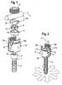
- shows a perspective exploded view of the bone anchoring device with a spinal rod according to an embodiment.
- Fig. 2:
- shows the bone anchoring device of
Fig. 1 in an assembled state without rod and fixation screw. - Fig. 3:
- shows a sectional view of the bone anchoring device of
Fig. 1 , the section being taken perpendicular to the rod axis. - Fig. 4:
- shows a sectional view of the bone anchoring device of
Fig. 1 , the section being taken along the rod axis. - Fig. 5:
- shows a perspective view of a seat member of the bone anchoring device.
- Fig. 6:
- shows a side view of the seat member of
Fig. 5 . - Fig. 7:
- shows a sectional view of the seat member, the section being taken along line A-A in
Fig. 6 . - Fig. 8:
- shows a perspective view of a first pressure member of the bone anchoring device.
- Fig. 9:
- shows a top view of the first pressure member of
Fig. 8 . - Fig. 10:
- shows a side view of the first pressure member of
Fig. 8 . - Fig. 11:
- shows a sectional view of the first pressure member along line B-B of
Fig. 10 . - Fig. 12:
- shows a perspective view of a second pressure member of the bone anchoring device from below.
- Fig. 13:
- shows a top view of the second pressure member of
Fig. 12 . - Fig. 14:
- shows a sectional view of the second pressure member along line C-C of
Fig. 13 . - Fig. 15:
- shows a sectional view of the bone anchoring element, the seat member and the first pressure member.
- Fig. 16:
- shows a perspective view of an assembly including the bone anchoring element, the seat member and the first pressure member.
- Figs. 17a)
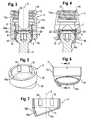
- to 17c): shows steps of use of the bone anchoring device according to the first embodiment.
- Figs. 18a)
- to 18c): show steps adjusting the seat member relative to the receiving part according to a first example of a method.
- Fig. 19:
- shows a top view of a support block for adjusting the seat member relative to the receiving part.
- Fig. 20:
- shows a sectional view of the support block with the bone anchoring device inserted, the section being taken along the rod axis.
- Fig. 21
- shows a perspective view of the bone anchoring device with an insertion tool.
- Fig. 22
- shows an enlarged portion of the the device of
Fig. 21 . - Fig. 23
- shows a perspective view of the bone anchoring device and a portion of another example for an insertion tool.
- As shown in
Figs. 1 and 2 , a bone anchoring device according to an embodiment comprises abone anchoring element 1 in the form of a bone screw having a threadedshaft 2 and ahead 3. Thehead 3 is typically spherically-shaped and has arecess 3 a for engagement with a driver. Thehead 3 is held in a receivingpart 4 that couples thebone anchoring element 1 to astabilization rod 100. In the receivingpart 4, aseat member 5 providing a seat for thehead 3 of thebone anchoring element 1, afirst pressure member 6 and asecond pressure member 7 for exerting pressure onto thehead 3 of the bone anchoring element are arranged. Further, a fixation element in the form of afixation screw 8 is provided for securing and fixing therod 100 in the receivingpart 4. When the bone anchoring device is assembled but the angular position of the bone anchoring element not yet fixed, thebone anchoring element 1 can pivot with an enlarged pivot angle in an unlimited number of directions as shown by the arrows inFig. 2 , depending on the position of theseat member 5 within the receivingpart 4. - The receiving
part 4 will be described with reference toFigs. 1 to 4 . It has atop end 4a and abottom end 4b, a central axis C and acoaxial bore 9 extending from thetop end 4a to thebottom end 4b. Adjacent to thetop end 4a a substantiallyU-shaped recess 10 is provided, which forms a channel for receiving therod 100. By means of therecess 10 twofree legs internal thread 12 cooperating with thefixation screw 8. At the lower portion of thebore 9 near thebottom end 4b astop 13 in the form of an annular edge is provided for preventing theseat member 5 from escaping through theopening 14 at thebottom end 4b. It shall be noted that thebore 9 is not restricted to the specific shape of the bore showing in the drawings but can have different portions with different diameters. - The
seat member 5 is shown in particular inFigs. 5 to 7 . It comprises a hollow cylindricalfirst portion 15, the inner diameter of which is slightly larger than the maximum diameter of the spherically-shapedhead 3 and the outer diameter, of which is slightly smaller than the inner diameter of thebore 9, so that theseat member 5 insertable into thebore 9. The axial length of thefirst portion 15 is such that when thehead 3 rests within theseat portion 16, thefirst portion 15 projects above thehead 3. Adjacent thefirst portion 15, theseat member 5 comprises a hollowsecond portion 16, which has an internal spherically-shapedsurface 16a for providing a seat for the spherically-shapedhead 3. Theouter surface 16b of thesecond portion 16 is also spherically-shaped with an outer diameter that is smaller than the outer diameter of the first hollowcylindrical portion 15. - As can be seen in particular in
Fig. 7 , thesecond portion 16 is asymmetric with respect to a plane including the cylinder axis Z. This is achieved in that thelower edge 16c is inclined with respect to the hollow cylindricalfirst portion 15 at an angle ∝. By means of this, thescrew element 1 can pivot when it is seated in theseat 16a at a greater angle to one side relative to the cylinder axis Z compared to the opposite side. It shall be noted that themember 5 can be sized such that the pivot angle of the screw element with respect to the one side can be only as much as approximately 10° and can be as much as approximately 40° to 50° to the opposite side. At the same time, the size of the pivot angle is limited to the extent that the head has still an adequate support in the seat member. Thesecond portion 16 is not limited to the design shown. For example, the asymmetry can be generated by a cut-out in a hollow spherical-shaped portion allowing the shank to pivot only through the cut-out. Theinner surface 16a is shown as being a spherically-shaped surface. However, it can have another shape, such as, for example any tapering shape, which is sized so as to prevent falling out of thehead 3. - The
seat member 5 further comprises a plurality ofcoaxial recesses 18 on the inner wall of thefirst portion 15, which open to the free end of thefirst portion 15 and end at a distance from the lower end of thefirst portion 15. Therecesses 18 are provided for a form locking engagement with corresponding projections on thefirst pressure element 6. The number and shape of therecesses 18 is not limited to the number and shape of the recesses shown in the Figures, for example, only one recess is necessary for a form lock connection between thefirst pressure element 6 and theseat member 5. - As can be seen in particular in
Figs. 3 and 4 , theseat member 5 abuts on theannular edge 13 of the receiving part, when it is inserted into the receivingpart 4 and moved downward along thebore 9. At least a portion of thesecond portion 16 of the seat member extends out of thelower opening 14 of the receiving part. Theseat member 5 is rotatable within the receivingpart 4, so that theinclined edge 16c can assume any position relative to theU-shaped recess 10. As a consequence thereof, the position with the enlarged pivot angle of theanchoring element 1 can assume any orientation with respect to theU-shaped recess 10 and therefore with respect to the rod axis L. - The
first pressure member 6 will now be explained specifically with reference toFigs. 8 to 11 . Thefirst pressure member 6 has a substantially hollowcylindrical portion 19, the outer diameter of which is only slightly smaller than the inner diameter of the first hollowcylindrical portion 15 of the seat member so that, as can be seen inFigs. 3 and 4 , thefirst pressure member 6 can be inserted into thefirst portion 15 of theseat member 5 and is axially movable with respect to the seat member. On its side facing thehead 3, thefirst pressure member 6 has arecess 20, which is in this embodiment a spherically-shaped recess with an inner diameter adapted to the diameter of thehead 3, so that thefirst pressure member 6 can exert pressure onto thehead 3. When thefirst pressure member 6 is inserted, it rests on thehead 3. It has such an axial length that it projects above theseat member 5, as can be seen inFigs. 3 and 4 . At the outer surface of the cylindrical portion 19 a plurality of coaxially extendingprojections 21 are provided, which engage therecesses 18 of theseat member 5 to form a form locking connection between the first pressure member and the seat member. Therecesses 18 at the seat member element form also guides for an axial movement of the first pressure member. Instead of the plurality of recesses and projections at the inner surface of the seat member and the outer surface of the first pressure member, respectively, any other connection between the seat member and the first pressure member, which allows the transmission of rotational forces from the first pressure member to the seat member and is conceivable. Theprojections 21 end at a distance from the top end and can comprise achamfer 21a to facilitate engagement with the correspondingrecesses 18 of theseat member 5. - On its end opposite to the
recess 20 the first pressure element comprises anengagement structure 22 for engagement with a driver, in the embodiment shown, it is a hexagon recess. - The
second pressure member 7 will be explained with reference toFigs. 12 to 14 . Thesecond pressure element 7 is substantially cylindrical and has on its side opposite to thehead 3 a cylindrically-shapedrecess 23, which is sized so as to guide therod 100 therein. By means of therecess 23 twolegs recess 23, the second pressure member comprises acoaxial recess 25, which is sized such that the second pressure member can rest on thecylindrical portion 19 of the first pressure member. Thesecond pressure member 7 further comprises a shallow coaxial bore 26 to allow access to the first pressure member with a driver. On the outer sidewall of thelegs coaxial recesses second pressure member 7 can be prevented from rotating and from escaping through thetop end 4a of the receivingpart 4, for example, by means ofpins Fig. 3 . - When the second pressure element is inserted, it abuts on the first pressure element in such a way that there is a
gap 29 between theseat member 5 and thesecond pressure element 7, so that thesecond pressure element 7 does not press onto theseat member 5. - As shown in
Figs. 15 and 16 , the form lock connection between thefirst pressure element 6 and theseat member 5 allows to transmit a rotational force exerted by driver, which engages the first pressure element at therecess 22, to theseat member 5, so that theseat member 5 rotates with thefirst pressure element 6. Since the form lock connection between thefirst pressure member 6 and theseat member 5 is such that the first pressure member can slide in an axial direction with respect to the seat member, the second pressure element can exert pressure onto the first pressure element to press thehead 3 against theseat member 5. - The bone anchoring device as a whole or in part is made of a bio-compatible material, such as a bio-compatible metal, such as titanium, stainless steel, bio-compatible alloys such as nitinol or others or bio-compatible plastic materials, such as, for example, medical grade polyethere-therketone (PEEK). The parts of the bone anchoring device can be made all of the same material or can be made of different materials.
- The steps of use of the bone anchoring device are shown in
Figs. 17a)-17c ). The bone anchoring device may be pre-assembled in such a way that theseat member 5, thebone anchoring element 1, thefirst pressure element 6 and thesecond pressure element 7 are inserted into the receivingpart 4 and secured against falling out as well as against rotation of thesecond pressure element 7, for example, by means of thepins recess 23 of the second pressure element is aligned with theU-shaped recess 12 of the receiving part. The seat member abuts on theannular edge 13 of the receiving part. In the pre-assembled state, thehead 3 can freely pivot within theseat member 5. In a next step, thebone anchoring element 1 is screwed into a bone part or a vertebra. Usually a plurality of bone anchoring elements are used and connected through therod 100. Before insertion of therod 100, the receiving parts are aligned through pivoting the receiving parts relative to thehead 3. To adjust the position of theseat member 5 in view of the desired direction with enlarged pivot angle, thefirst pressure element 6 is rotated with a driver. Since theseat member 5 is positively connected to thefirst pressure member 6, it rotates with thefirst pressure member 6. Then, as shown inFig. 17b ), the rod is inserted. Next, as shown inFig. 17c ) thefixation screw 8 is screwed-in between the legs of the receiving part and tightened so that therod 100 presses onto thesecond pressure element 7, which itself presses onto the first pressure element thereby locking the head in theseat member 5. Simultaneously, the seat member is pressed against theannular edge 13 and is thereby fixed in its rotational position. - Modifications of the embodiment are conceivable. For example, it is possible to omit the second pressure element and to press directly with the rod onto the first pressure element. In a further modification, the second pressure element has legs, which extend above the rod and the
fixation element 8 is a two-part fixation element with an outer screw acting onto the second pressure element and an inner screw acting onto the rod. In a further modification, all kinds of bone anchors can be used for the bone anchoring element, such as bone nails, other types of bone screws, canulated screws, etc. The head and the shaft of the bone anchoring element may be separate parts that are connectable to each other. Figs. 18 to 20 show an example of a tool and a method for adjusting the rotational position of theseat member 5. Asupport block 30 is provided, which comprises alongitudinal bore 31 extending from atop surface 30a into thesupport block 30. In thetop surface 30a arecess 32 is formed that extends into the support block, which has aninner surface 32a corresponding to theouter surface 16b of thesecond portion 16 of theseat member 5. Hence, therecess 32 is asymmetrical and adapted to the shape of thelower portion 16 of theseat member 5. As shown inFigs. 19 and 20 , when the pre-assembled bone anchoring device is inserted with the threadedshaft 2 into thehole 31, thesecond portion 16 of the seat member rests in therecess 32 and is prevented from rotating therein due to the form lock connection.- Once the bone anchoring device is fully inserted in the
bore 31, thescrew element 1 and the receiving part including thesecond pressure element 7 are rotatable with respect to theseat member 5 and thefirst pressure element 6. Hence, the receiving part can be rotated with respect to the seat member and the first pressure element, so that theseat member 5 has the desired orientation. Two examples are shown inFigs. 18b and 18c . - The adjustment using the support block can be made before the actual surgery takes place and can serve for a pre-orientation of the
seat member 5. For holding this orientation of the seat member an insertion tool for inserting the screw member into the bone can be used which is shown inFigs. 21 and 22 . Theinsertion tool 50 has afirst portion 51 with ahandle 52 at one end, atip 53 at the other end and adjacent the tip an externally threadedportion 54 cooperating with theinternal thread 12 on the legs of the receivingpart 4. The tool further has asecond portion 55 with twoside flanges U-shaped recess 10 of the receiving part. Thefirst portion 51 is rotatable with respect to thesecond portion 55. When the tool engages the bone anchoring device, thesecond portion 55 holds the receiving part through engagement with the U-shaped recess and thetip 53 presses onto the screw head when the threadedportion 54 is screwed between the legs. The orientation of the seat member is thereby secured by the pre-tension and the shaft can be inserted into the bone with the insertion tool. - In an alternative method, the bone anchoring device can be inserted into the bone with a
tool 60 shown inFig. 23 which has asimple drive 61 portion at its end, for example a torx drive. In this case, the rotational orientation of the seat member is not maintained during insertion. After insertion of the shaft, a separate driver for engagement with therecess 22 in the first pressure element is used to adjust the rotational position of the seat member from the top end. A visible mark can be provided at the drive to serve as an indication for the position of the seat member.
Claims (19)
- Bone anchoring device comprising
a bone anchoring element (1) having a head (3) and a shaft (3) configured to be anchored in a bone or a vertebra;
a receiving part (4) for coupling the bone anchoring element to a stabilization element (100), the receiving part having
a top end (4a) and bottom end (4b), a bore (9) extending from the top end to the bottom end and having a bore axis (C),
a recess (10) for receiving the stabilization element, the recess being in communication with said bore (9);
a seat member (5) arranged within the bore (9) and being rotatable around the bore axis, the seat member forming a seat for pivotably holding the head,
wherein the seat member is configured to allow a greater pivot angle of the bone anchoring element to one side compared to the other side relative to the bore axis (C);
a pressure member (6) which contacts the head to exert pressure onto the head, the pressure member (6) being connected to the seat member (5) so as to allow an angle adjustment of the seat member. - The bone anchoring device of claim 1 wherein the pressure member (6) is axially movable with respect to the seat member (5).
- The bone anchoring device of claim 1 or 2, wherein the pressure member (6) is connected to the seat member so as to transmit rotational forces to the seat member (5).
- The bone anchoring device of one of claims 1 to 3, wherein the seat member (5) abuts against a stop (13) in the receiving part (4).
- The bone anchoring device of one of claims 1 to 4, wherein the seat member (5) has an at least partially spherical inner surface (16a).
- The bone anchoring device of one of claims 1 to 5, wherein the seat member (5) projects at least partly out of the receiving part (4) at the bottom end (4b).
- The bone anchoring device of one of claims 1 to 6, wherein the seat member has an inclined lower edge (16c) so as to provide an enlarged pivot angle to one side.
- The bone anchoring device of one of claims 1 to 7, wherein the pressure member (6) and the seat member (5) are connected via a form lock connection.
- The bone anchoring device of claim 6, wherein the seat member (5) comprises at least one axial recess (18) or projection which engages with a corresponding projection (21) or recess at the pressure member 86).
- The bone anchoring device of one of claims 1 to 9, wherein the pressure member has an engagement portion (22) for engagement with a driver.
- The bone anchoring device of claim 10, wherein the engagement portion is provided at a side of the pressure member which faces away from the head (3).
- The bone anchoring device of one of claims 1 to 11, wherein the seat member (5) has a cylindrical portion (15) and the pressure member (6) has a cylindrical portion which are axially movable relative to each other but rotationally fixed.
- The bone anchoring device of one of claims 1 to 12, wherein the pressure member (6) is a first pressure member and wherein a second pressure member (7) is provided in the receiving part on top of the first pressure member and wherein the second pressure member (7) has a recess (23) for guiding the fixation element (100).
- The bone anchoring device of claim 15, wherein in a state in which the head is locked in the seat member (5) the second pressure member presses onto the first pressure member (6) without touching the seat member.
- The bone anchoring device of claim 13 or 14, wherein the second pressure member is rotatable with respect to the first pressure member (6).
- The bone anchoring device of one of claims 1 to 15, wherein the second pressure member (7) is secured against rotation in the receiving part (4).
- The bone anchoring device of one of claims 1 to 16, wherein the recess (10) for the rod is U-shaped.
- A method for adjusting the pivot angle of a polyaxial bone anchoring device, wherein the bone anchoring device comprises
a bone anchoring element (1) having a head (3) and a shaft (3) configured to be anchored in a bone or a vertebra;
a receiving part (4) for coupling the bone anchoring element to a stabilization element (100), the receiving part having
a top end (4a) and bottom end (4b), a bore (9) extending from the top end to the bottom end and having a bore axis (C),
a substantially U-shaped recess (10) for receiving the stabilization element, the recess being in communication with said bore (9);
a seat member (5) arranged within the bore (9) and being rotatable around the bore axis, the seat member forming a seat for pivotably holding the head,
wherein the seat member is configured to allow a greater pivot angle of the bone anchoring element to one side compared to the other side relative to the bore axis (C);
the method comprising the steps:supporting the seat member or the receiving part (4) in a support device (30);rotating the receiving part (4) with respect to the seat member (5) to adjust the orientation of an enlarged pivot angle. - The method of claim 18, wherein the seat member (5) is supported in a recess (32a) in the support device (30) in a form locking manner.
Priority Applications (7)
| Application Number | Priority Date | Filing Date | Title |
|---|---|---|---|
| EP10194787.7AEP2462889B1 (en) | 2010-12-13 | 2010-12-13 | Bone anchoring device |
| ES10194787TES2436067T3 (en) | 2010-12-13 | 2010-12-13 | Bone anchoring device |
| TW100145177ATW201223500A (en) | 2010-12-13 | 2011-12-08 | Bone anchoring device |
| JP2011268930AJP5939779B2 (en) | 2010-12-13 | 2011-12-08 | Bone fixation device and method for adjusting the pivot angle of a polyaxial bone fixation device |
| KR1020110130915AKR20120065938A (en) | 2010-12-13 | 2011-12-08 | Bone anchoring device |
| CN201110404385.4ACN102525618B (en) | 2010-12-13 | 2011-12-08 | Bone anchoring device |
| US13/324,616US9597120B2 (en) | 2010-12-13 | 2011-12-13 | Bone anchoring device |
Applications Claiming Priority (1)
| Application Number | Priority Date | Filing Date | Title |
|---|---|---|---|
| EP10194787.7AEP2462889B1 (en) | 2010-12-13 | 2010-12-13 | Bone anchoring device |
Publications (2)
| Publication Number | Publication Date |
|---|---|
| EP2462889A1true EP2462889A1 (en) | 2012-06-13 |
| EP2462889B1 EP2462889B1 (en) | 2013-08-21 |
Family
ID=43778643
Family Applications (1)
| Application Number | Title | Priority Date | Filing Date |
|---|---|---|---|
| EP10194787.7AActiveEP2462889B1 (en) | 2010-12-13 | 2010-12-13 | Bone anchoring device |
Country Status (7)
| Country | Link |
|---|---|
| US (1) | US9597120B2 (en) |
| EP (1) | EP2462889B1 (en) |
| JP (1) | JP5939779B2 (en) |
| KR (1) | KR20120065938A (en) |
| CN (1) | CN102525618B (en) |
| ES (1) | ES2436067T3 (en) |
| TW (1) | TW201223500A (en) |
Cited By (7)
| Publication number | Priority date | Publication date | Assignee | Title |
|---|---|---|---|---|
| US9192415B1 (en) | 2008-02-06 | 2015-11-24 | Nuvasive, Inc. | Systems and methods for holding and implanting bone anchors |
| US9198698B1 (en) | 2011-02-10 | 2015-12-01 | Nuvasive, Inc. | Minimally invasive spinal fixation system and related methods |
| EP2938278A4 (en)* | 2012-12-31 | 2016-04-13 | Globus Medical Inc | ORTHOPEDIC FASTENING DEVICES AND METHODS FOR INSTALLING THEM |
| US9486256B1 (en) | 2013-03-15 | 2016-11-08 | Nuvasive, Inc. | Rod reduction assemblies and related methods |
| EP3115008A1 (en) | 2015-07-09 | 2017-01-11 | Silony Medical International AG | Bone anchoring element |
| US9974577B1 (en) | 2015-05-21 | 2018-05-22 | Nuvasive, Inc. | Methods and instruments for performing leveraged reduction during single position spine surgery |
| US10398481B2 (en) | 2016-10-03 | 2019-09-03 | Nuvasive, Inc. | Spinal fixation system |
Families Citing this family (24)
| Publication number | Priority date | Publication date | Assignee | Title |
|---|---|---|---|---|
| US8007522B2 (en) | 2008-02-04 | 2011-08-30 | Depuy Spine, Inc. | Methods for correction of spinal deformities |
| US9504495B2 (en)* | 2011-02-11 | 2016-11-29 | Blackstone Medical, Inc. | Multi-axial pedicle fixation assembly and method for use |
| US9603630B2 (en)* | 2011-04-29 | 2017-03-28 | Warsaw Orthopedic, Inc. | Rotatable base multi-axial screw assembly |
| ES2546157T3 (en) | 2011-10-27 | 2015-09-21 | Biedermann Technologies Gmbh & Co. Kg | Wide angle polyaxial bone anchoring device |
| US20140025120A1 (en)* | 2012-07-18 | 2014-01-23 | Warsaw Orthopedic, Inc. | Multi-axial bone fastener and system |
| US9782204B2 (en) | 2012-09-28 | 2017-10-10 | Medos International Sarl | Bone anchor assemblies |
| US20140257411A1 (en)* | 2013-03-08 | 2014-09-11 | Warsaw Orthopedic, Inc. | Bone fastener and methods of use |
| US9775660B2 (en) | 2013-03-14 | 2017-10-03 | DePuy Synthes Products, Inc. | Bottom-loading bone anchor assemblies and methods |
| US9724145B2 (en) | 2013-03-14 | 2017-08-08 | Medos International Sarl | Bone anchor assemblies with multiple component bottom loading bone anchors |
| US10342582B2 (en) | 2013-03-14 | 2019-07-09 | DePuy Synthes Products, Inc. | Bone anchor assemblies and methods with improved locking |
| US9259247B2 (en) | 2013-03-14 | 2016-02-16 | Medos International Sarl | Locking compression members for use with bone anchor assemblies and methods |
| US20140277153A1 (en) | 2013-03-14 | 2014-09-18 | DePuy Synthes Products, LLC | Bone Anchor Assemblies and Methods With Improved Locking |
| US10918419B2 (en)* | 2014-04-01 | 2021-02-16 | K2M, Inc. | Spinal fixation device |
| US10368916B2 (en)* | 2017-01-11 | 2019-08-06 | Warsaw Orthopedic, Inc. | Spinal implant system and methods of use |
| US11051861B2 (en) | 2018-06-13 | 2021-07-06 | Nuvasive, Inc. | Rod reduction assemblies and related methods |
| EP3785649B1 (en)* | 2019-08-30 | 2022-08-03 | Biedermann Technologies GmbH & Co. KG | Bone anchoring device |
| WO2021061970A1 (en)* | 2019-09-24 | 2021-04-01 | Corelink, Llc | Polyaxial bone screw |
| EP3878386B1 (en)* | 2020-03-12 | 2023-08-30 | Biedermann Technologies GmbH & Co. KG | Coupling device for use with a bone anchoring element and bone anchoring device with such a coupling device |
| CN112754632B (en)* | 2020-12-31 | 2022-08-16 | 北京市春立正达医疗器械股份有限公司 | Spine fixing nail and spine fixing nail rod system applying same |
| US12364515B2 (en) | 2021-03-05 | 2025-07-22 | Medos International Sàrl | Multi-feature polyaxial screw |
| WO2022184797A1 (en) | 2021-03-05 | 2022-09-09 | Medos International Sarl | Selectively locking polyaxial screw |
| WO2024237678A1 (en)* | 2023-05-18 | 2024-11-21 | (주)시지바이오 | Pedicle screw assembly |
| WO2024237679A1 (en)* | 2023-05-18 | 2024-11-21 | (주)시지바이오 | Pedicle screw assembly |
| WO2025018540A1 (en)* | 2023-07-20 | 2025-01-23 | (주)시지바이오 | Pedicle screw assembly |
Citations (9)
| Publication number | Priority date | Publication date | Assignee | Title |
|---|---|---|---|---|
| US6736820B2 (en) | 2000-11-10 | 2004-05-18 | Biedermann Motech Gmbh | Bone screw |
| US20050154391A1 (en) | 2003-12-30 | 2005-07-14 | Thomas Doherty | Bone anchor assemblies |
| US20070118123A1 (en) | 2005-11-21 | 2007-05-24 | Strausbaugh William L | Polyaxial bone anchors with increased angulation |
| US20070270842A1 (en)* | 2006-04-11 | 2007-11-22 | Bankoski Brian R | Minimally invasive fixation sysyem |
| US20080177260A1 (en)* | 2007-01-12 | 2008-07-24 | Lanx, Inc. | Bone fastener assembly |
| US20100145394A1 (en)* | 2008-11-03 | 2010-06-10 | Harvey Dustin M | Uni-planer bone fixation assembly |
| US20100152787A1 (en)* | 2007-07-26 | 2010-06-17 | Biotechni America Spine Group, Inc. | Spinal fixation assembly |
| US20100204735A1 (en)* | 2009-02-11 | 2010-08-12 | Gephart Matthew P | Wide Angulation Coupling Members For Bone Fixation System |
| US20100298891A1 (en)* | 2004-11-23 | 2010-11-25 | Jackson Roger P | Bone anchors with longitudinal connecting member engaging inserts and closures for fixation and optional angulation |
Family Cites Families (12)
| Publication number | Priority date | Publication date | Assignee | Title |
|---|---|---|---|---|
| US6981973B2 (en)* | 2003-08-11 | 2006-01-03 | Mckinley Laurence M | Low profile vertebral alignment and fixation assembly |
| AU2004266737B2 (en)* | 2003-08-20 | 2010-05-13 | Warsaw Orthopedic, Inc. | Multi-axial orthopedic device and system, e.g. for spinal surgery |
| US20050080415A1 (en)* | 2003-10-14 | 2005-04-14 | Keyer Thomas R. | Polyaxial bone anchor and method of spinal fixation |
| JP2007516811A (en)* | 2003-12-30 | 2007-06-28 | デピュイ・スパイン・エスエイアールエル | Bone anchor assembly and method for manufacturing bone anchor assembly |
| US7678137B2 (en)* | 2004-01-13 | 2010-03-16 | Life Spine, Inc. | Pedicle screw constructs for spine fixation systems |
| GB0720762D0 (en)* | 2007-10-24 | 2007-12-05 | Depuy Spine Sorl | Assembly for orthopaedic surgery |
| US8419778B2 (en)* | 2010-01-15 | 2013-04-16 | Ebi, Llc | Uniplanar bone anchor system |
| US9232969B2 (en)* | 2010-10-29 | 2016-01-12 | Warsaw Orthopedic, Inc. | Directional control for a multi-axial screw assembly |
| US8337530B2 (en)* | 2011-03-09 | 2012-12-25 | Zimmer Spine, Inc. | Polyaxial pedicle screw with increased angulation |
| EP2918237A1 (en)* | 2011-09-15 | 2015-09-16 | Biedermann Technologies GmbH & Co. KG | Polyaxial bone anchoring device with enlarged pivot angle |
| ES2546157T3 (en)* | 2011-10-27 | 2015-09-21 | Biedermann Technologies Gmbh & Co. Kg | Wide angle polyaxial bone anchoring device |
| EP2604204B1 (en)* | 2011-12-13 | 2014-10-01 | Biedermann Technologies GmbH & Co. KG | Monoplanar bone anchoring device with selectable pivot plane |
- 2010
- 2010-12-13ESES10194787Tpatent/ES2436067T3/enactiveActive
- 2010-12-13EPEP10194787.7Apatent/EP2462889B1/enactiveActive
- 2011
- 2011-12-08KRKR1020110130915Apatent/KR20120065938A/ennot_activeWithdrawn
- 2011-12-08TWTW100145177Apatent/TW201223500A/enunknown
- 2011-12-08JPJP2011268930Apatent/JP5939779B2/ennot_activeExpired - Fee Related
- 2011-12-08CNCN201110404385.4Apatent/CN102525618B/ennot_activeExpired - Fee Related
- 2011-12-13USUS13/324,616patent/US9597120B2/enactiveActive
Patent Citations (9)
| Publication number | Priority date | Publication date | Assignee | Title |
|---|---|---|---|---|
| US6736820B2 (en) | 2000-11-10 | 2004-05-18 | Biedermann Motech Gmbh | Bone screw |
| US20050154391A1 (en) | 2003-12-30 | 2005-07-14 | Thomas Doherty | Bone anchor assemblies |
| US20100298891A1 (en)* | 2004-11-23 | 2010-11-25 | Jackson Roger P | Bone anchors with longitudinal connecting member engaging inserts and closures for fixation and optional angulation |
| US20070118123A1 (en) | 2005-11-21 | 2007-05-24 | Strausbaugh William L | Polyaxial bone anchors with increased angulation |
| US20070270842A1 (en)* | 2006-04-11 | 2007-11-22 | Bankoski Brian R | Minimally invasive fixation sysyem |
| US20080177260A1 (en)* | 2007-01-12 | 2008-07-24 | Lanx, Inc. | Bone fastener assembly |
| US20100152787A1 (en)* | 2007-07-26 | 2010-06-17 | Biotechni America Spine Group, Inc. | Spinal fixation assembly |
| US20100145394A1 (en)* | 2008-11-03 | 2010-06-10 | Harvey Dustin M | Uni-planer bone fixation assembly |
| US20100204735A1 (en)* | 2009-02-11 | 2010-08-12 | Gephart Matthew P | Wide Angulation Coupling Members For Bone Fixation System |
Cited By (22)
| Publication number | Priority date | Publication date | Assignee | Title |
|---|---|---|---|---|
| US9757166B1 (en) | 2008-02-06 | 2017-09-12 | Nuvasive, Inc. | Systems and methods for holding and implanting bone anchors |
| US11311320B2 (en) | 2008-02-06 | 2022-04-26 | Nuvasive, Inc. | Systems and methods for introducing a bone anchor |
| US10426526B2 (en) | 2008-02-06 | 2019-10-01 | Nuvasive, Inc. | Systems and methods for introducing a bone anchor |
| US12285195B2 (en) | 2008-02-06 | 2025-04-29 | Globus Medical Inc. | Systems and methods for introducing a bone anchor |
| US9492208B1 (en) | 2008-02-06 | 2016-11-15 | Nuvasive, Inc. | Systems and methods for holding and implanting bone anchors |
| US9192415B1 (en) | 2008-02-06 | 2015-11-24 | Nuvasive, Inc. | Systems and methods for holding and implanting bone anchors |
| US10004544B2 (en) | 2008-02-06 | 2018-06-26 | Nuvasive, Inc. | Systems and methods for introducing a bone anchor |
| US10426527B2 (en) | 2011-02-10 | 2019-10-01 | Nuvasive, Inc. | Minimally invasive spinal fixation system and related methods |
| US9649140B1 (en) | 2011-02-10 | 2017-05-16 | Nuvasive, Inc. | Minimally invasive spinal fixation system and related methods |
| US11723698B2 (en) | 2011-02-10 | 2023-08-15 | Nuvasive, Inc. | Minimally invasive spinal fixation system and related methods |
| US9198698B1 (en) | 2011-02-10 | 2015-12-01 | Nuvasive, Inc. | Minimally invasive spinal fixation system and related methods |
| US11406429B2 (en) | 2011-02-10 | 2022-08-09 | Nuvasive, Inc. | Minimally invasive spinal fixation system and related methods |
| EP2938278A4 (en)* | 2012-12-31 | 2016-04-13 | Globus Medical Inc | ORTHOPEDIC FASTENING DEVICES AND METHODS FOR INSTALLING THEM |
| US9486256B1 (en) | 2013-03-15 | 2016-11-08 | Nuvasive, Inc. | Rod reduction assemblies and related methods |
| US9974577B1 (en) | 2015-05-21 | 2018-05-22 | Nuvasive, Inc. | Methods and instruments for performing leveraged reduction during single position spine surgery |
| US10682166B2 (en) | 2015-05-21 | 2020-06-16 | Nuvasive, Inc. | Methods and instruments for performing leveraged reduction during single position spine surgery |
| US11771477B2 (en) | 2015-05-21 | 2023-10-03 | Nuvasive, Inc. | Methods and instruments for performing leveraged reduction during single position spine surgery |
| EP3115008A1 (en) | 2015-07-09 | 2017-01-11 | Silony Medical International AG | Bone anchoring element |
| US11766281B2 (en) | 2016-10-03 | 2023-09-26 | Nuvasive, Inc. | Spinal fixation system |
| US11197697B2 (en) | 2016-10-03 | 2021-12-14 | Nuvasive, Inc. | Spinal fixation system |
| US10398481B2 (en) | 2016-10-03 | 2019-09-03 | Nuvasive, Inc. | Spinal fixation system |
| US12324611B2 (en) | 2016-10-03 | 2025-06-10 | Nuvasive, Inc. | Spinal fixation system |
Also Published As
| Publication number | Publication date |
|---|---|
| JP2012125569A (en) | 2012-07-05 |
| US20120185003A1 (en) | 2012-07-19 |
| JP5939779B2 (en) | 2016-06-22 |
| EP2462889B1 (en) | 2013-08-21 |
| CN102525618A (en) | 2012-07-04 |
| TW201223500A (en) | 2012-06-16 |
| ES2436067T3 (en) | 2013-12-26 |
| CN102525618B (en) | 2016-01-20 |
| US9597120B2 (en) | 2017-03-21 |
| KR20120065938A (en) | 2012-06-21 |
Similar Documents
| Publication | Publication Date | Title |
|---|---|---|
| EP2462889B1 (en) | Bone anchoring device | |
| US11937852B2 (en) | Polyaxial bone anchoring device with enlarged pivot angle | |
| EP2559390B1 (en) | Polyaxial bone anchoring device with enlarged pivot angle | |
| US9277938B2 (en) | Polyaxial bone anchoring system | |
| EP2586392B1 (en) | High angulation polyaxial bone anchoring device | |
| EP2570090B1 (en) | Polyaxial bone anchoring device with enlarged pivot angle | |
| EP2985001B1 (en) | Polyaxial bone anchoring device | |
| EP3047812B1 (en) | Polyaxial bone anchoring device | |
| US9192417B2 (en) | Monoplanar bone anchoring device with selectable pivot plane | |
| EP1923011A1 (en) | Bone anchoring device | |
| EP2606841A1 (en) | Polyaxial bone anchoring device | |
| EP2586391A1 (en) | A locking assembly for a polyaxial bone anchoring device | |
| EP2674123A1 (en) | Polyaxial bone anchoring device |
Legal Events
| Date | Code | Title | Description |
|---|---|---|---|
| PUAI | Public reference made under article 153(3) epc to a published international application that has entered the european phase | Free format text:ORIGINAL CODE: 0009012 | |
| 17P | Request for examination filed | Effective date:20111222 | |
| AK | Designated contracting states | Kind code of ref document:A1 Designated state(s):AL AT BE BG CH CY CZ DE DK EE ES FI FR GB GR HR HU IE IS IT LI LT LU LV MC MK MT NL NO PL PT RO RS SE SI SK SM TR | |
| AX | Request for extension of the european patent | Extension state:BA ME | |
| GRAP | Despatch of communication of intention to grant a patent | Free format text:ORIGINAL CODE: EPIDOSNIGR1 | |
| GRAS | Grant fee paid | Free format text:ORIGINAL CODE: EPIDOSNIGR3 | |
| GRAA | (expected) grant | Free format text:ORIGINAL CODE: 0009210 | |
| AK | Designated contracting states | Kind code of ref document:B1 Designated state(s):AL AT BE BG CH CY CZ DE DK EE ES FI FR GB GR HR HU IE IS IT LI LT LU LV MC MK MT NL NO PL PT RO RS SE SI SK SM TR | |
| REG | Reference to a national code | Ref country code:GB Ref legal event code:FG4D | |
| REG | Reference to a national code | Ref country code:CH Ref legal event code:NV Representative=s name:NOVAGRAAF INTERNATIONAL SA, CH Ref country code:CH Ref legal event code:EP | |
| REG | Reference to a national code | Ref country code:AT Ref legal event code:REF Ref document number:627575 Country of ref document:AT Kind code of ref document:T Effective date:20130915 | |
| REG | Reference to a national code | Ref country code:IE Ref legal event code:FG4D | |
| REG | Reference to a national code | Ref country code:DE Ref legal event code:R096 Ref document number:602010009608 Country of ref document:DE Effective date:20131017 | |
| REG | Reference to a national code | Ref country code:ES Ref legal event code:FG2A Ref document number:2436067 Country of ref document:ES Kind code of ref document:T3 Effective date:20131226 | |
| REG | Reference to a national code | Ref country code:NL Ref legal event code:VDEP Effective date:20130821 Ref country code:AT Ref legal event code:MK05 Ref document number:627575 Country of ref document:AT Kind code of ref document:T Effective date:20130821 | |
| REG | Reference to a national code | Ref country code:LT Ref legal event code:MG4D | |
| PG25 | Lapsed in a contracting state [announced via postgrant information from national office to epo] | Ref country code:PT Free format text:LAPSE BECAUSE OF FAILURE TO SUBMIT A TRANSLATION OF THE DESCRIPTION OR TO PAY THE FEE WITHIN THE PRESCRIBED TIME-LIMIT Effective date:20131223 Ref country code:HR Free format text:LAPSE BECAUSE OF FAILURE TO SUBMIT A TRANSLATION OF THE DESCRIPTION OR TO PAY THE FEE WITHIN THE PRESCRIBED TIME-LIMIT Effective date:20130821 Ref country code:SE Free format text:LAPSE BECAUSE OF FAILURE TO SUBMIT A TRANSLATION OF THE DESCRIPTION OR TO PAY THE FEE WITHIN THE PRESCRIBED TIME-LIMIT Effective date:20130821 Ref country code:AT Free format text:LAPSE BECAUSE OF FAILURE TO SUBMIT A TRANSLATION OF THE DESCRIPTION OR TO PAY THE FEE WITHIN THE PRESCRIBED TIME-LIMIT Effective date:20130821 Ref country code:CY Free format text:LAPSE BECAUSE OF FAILURE TO SUBMIT A TRANSLATION OF THE DESCRIPTION OR TO PAY THE FEE WITHIN THE PRESCRIBED TIME-LIMIT Effective date:20130828 Ref country code:LT Free format text:LAPSE BECAUSE OF FAILURE TO SUBMIT A TRANSLATION OF THE DESCRIPTION OR TO PAY THE FEE WITHIN THE PRESCRIBED TIME-LIMIT Effective date:20130821 Ref country code:NO Free format text:LAPSE BECAUSE OF FAILURE TO SUBMIT A TRANSLATION OF THE DESCRIPTION OR TO PAY THE FEE WITHIN THE PRESCRIBED TIME-LIMIT Effective date:20131121 Ref country code:IS Free format text:LAPSE BECAUSE OF FAILURE TO SUBMIT A TRANSLATION OF THE DESCRIPTION OR TO PAY THE FEE WITHIN THE PRESCRIBED TIME-LIMIT Effective date:20131221 | |
| PG25 | Lapsed in a contracting state [announced via postgrant information from national office to epo] | Ref country code:PL Free format text:LAPSE BECAUSE OF FAILURE TO SUBMIT A TRANSLATION OF THE DESCRIPTION OR TO PAY THE FEE WITHIN THE PRESCRIBED TIME-LIMIT Effective date:20130821 Ref country code:FI Free format text:LAPSE BECAUSE OF FAILURE TO SUBMIT A TRANSLATION OF THE DESCRIPTION OR TO PAY THE FEE WITHIN THE PRESCRIBED TIME-LIMIT Effective date:20130821 Ref country code:BE Free format text:LAPSE BECAUSE OF FAILURE TO SUBMIT A TRANSLATION OF THE DESCRIPTION OR TO PAY THE FEE WITHIN THE PRESCRIBED TIME-LIMIT Effective date:20130821 Ref country code:SI Free format text:LAPSE BECAUSE OF FAILURE TO SUBMIT A TRANSLATION OF THE DESCRIPTION OR TO PAY THE FEE WITHIN THE PRESCRIBED TIME-LIMIT Effective date:20130821 Ref country code:LV Free format text:LAPSE BECAUSE OF FAILURE TO SUBMIT A TRANSLATION OF THE DESCRIPTION OR TO PAY THE FEE WITHIN THE PRESCRIBED TIME-LIMIT Effective date:20130821 Ref country code:GR Free format text:LAPSE BECAUSE OF FAILURE TO SUBMIT A TRANSLATION OF THE DESCRIPTION OR TO PAY THE FEE WITHIN THE PRESCRIBED TIME-LIMIT Effective date:20131122 | |
| PG25 | Lapsed in a contracting state [announced via postgrant information from national office to epo] | Ref country code:CY Free format text:LAPSE BECAUSE OF FAILURE TO SUBMIT A TRANSLATION OF THE DESCRIPTION OR TO PAY THE FEE WITHIN THE PRESCRIBED TIME-LIMIT Effective date:20130821 | |
| PG25 | Lapsed in a contracting state [announced via postgrant information from national office to epo] | Ref country code:SK Free format text:LAPSE BECAUSE OF FAILURE TO SUBMIT A TRANSLATION OF THE DESCRIPTION OR TO PAY THE FEE WITHIN THE PRESCRIBED TIME-LIMIT Effective date:20130821 Ref country code:CZ Free format text:LAPSE BECAUSE OF FAILURE TO SUBMIT A TRANSLATION OF THE DESCRIPTION OR TO PAY THE FEE WITHIN THE PRESCRIBED TIME-LIMIT Effective date:20130821 Ref country code:EE Free format text:LAPSE BECAUSE OF FAILURE TO SUBMIT A TRANSLATION OF THE DESCRIPTION OR TO PAY THE FEE WITHIN THE PRESCRIBED TIME-LIMIT Effective date:20130821 Ref country code:RO Free format text:LAPSE BECAUSE OF FAILURE TO SUBMIT A TRANSLATION OF THE DESCRIPTION OR TO PAY THE FEE WITHIN THE PRESCRIBED TIME-LIMIT Effective date:20130821 Ref country code:NL Free format text:LAPSE BECAUSE OF FAILURE TO SUBMIT A TRANSLATION OF THE DESCRIPTION OR TO PAY THE FEE WITHIN THE PRESCRIBED TIME-LIMIT Effective date:20130821 Ref country code:DK Free format text:LAPSE BECAUSE OF FAILURE TO SUBMIT A TRANSLATION OF THE DESCRIPTION OR TO PAY THE FEE WITHIN THE PRESCRIBED TIME-LIMIT Effective date:20130821 | |
| PLBE | No opposition filed within time limit | Free format text:ORIGINAL CODE: 0009261 | |
| STAA | Information on the status of an ep patent application or granted ep patent | Free format text:STATUS: NO OPPOSITION FILED WITHIN TIME LIMIT | |
| 26N | No opposition filed | Effective date:20140522 | |
| PG25 | Lapsed in a contracting state [announced via postgrant information from national office to epo] | Ref country code:LU Free format text:LAPSE BECAUSE OF FAILURE TO SUBMIT A TRANSLATION OF THE DESCRIPTION OR TO PAY THE FEE WITHIN THE PRESCRIBED TIME-LIMIT Effective date:20131213 | |
| REG | Reference to a national code | Ref country code:DE Ref legal event code:R097 Ref document number:602010009608 Country of ref document:DE Effective date:20140522 | |
| REG | Reference to a national code | Ref country code:IE Ref legal event code:MM4A | |
| PG25 | Lapsed in a contracting state [announced via postgrant information from national office to epo] | Ref country code:IE Free format text:LAPSE BECAUSE OF NON-PAYMENT OF DUE FEES Effective date:20131213 | |
| PG25 | Lapsed in a contracting state [announced via postgrant information from national office to epo] | Ref country code:MC Free format text:LAPSE BECAUSE OF FAILURE TO SUBMIT A TRANSLATION OF THE DESCRIPTION OR TO PAY THE FEE WITHIN THE PRESCRIBED TIME-LIMIT Effective date:20130821 | |
| PG25 | Lapsed in a contracting state [announced via postgrant information from national office to epo] | Ref country code:SM Free format text:LAPSE BECAUSE OF FAILURE TO SUBMIT A TRANSLATION OF THE DESCRIPTION OR TO PAY THE FEE WITHIN THE PRESCRIBED TIME-LIMIT Effective date:20130821 | |
| PG25 | Lapsed in a contracting state [announced via postgrant information from national office to epo] | Ref country code:TR Free format text:LAPSE BECAUSE OF FAILURE TO SUBMIT A TRANSLATION OF THE DESCRIPTION OR TO PAY THE FEE WITHIN THE PRESCRIBED TIME-LIMIT Effective date:20130821 | |
| PG25 | Lapsed in a contracting state [announced via postgrant information from national office to epo] | Ref country code:BG Free format text:LAPSE BECAUSE OF FAILURE TO SUBMIT A TRANSLATION OF THE DESCRIPTION OR TO PAY THE FEE WITHIN THE PRESCRIBED TIME-LIMIT Effective date:20130821 Ref country code:HU Free format text:LAPSE BECAUSE OF FAILURE TO SUBMIT A TRANSLATION OF THE DESCRIPTION OR TO PAY THE FEE WITHIN THE PRESCRIBED TIME-LIMIT; INVALID AB INITIO Effective date:20101213 Ref country code:MK Free format text:LAPSE BECAUSE OF FAILURE TO SUBMIT A TRANSLATION OF THE DESCRIPTION OR TO PAY THE FEE WITHIN THE PRESCRIBED TIME-LIMIT Effective date:20130821 Ref country code:RS Free format text:LAPSE BECAUSE OF FAILURE TO SUBMIT A TRANSLATION OF THE DESCRIPTION OR TO PAY THE FEE WITHIN THE PRESCRIBED TIME-LIMIT Effective date:20131121 | |
| PG25 | Lapsed in a contracting state [announced via postgrant information from national office to epo] | Ref country code:MT Free format text:LAPSE BECAUSE OF FAILURE TO SUBMIT A TRANSLATION OF THE DESCRIPTION OR TO PAY THE FEE WITHIN THE PRESCRIBED TIME-LIMIT Effective date:20130821 | |
| REG | Reference to a national code | Ref country code:FR Ref legal event code:PLFP Year of fee payment:6 | |
| REG | Reference to a national code | Ref country code:FR Ref legal event code:PLFP Year of fee payment:7 | |
| PGFP | Annual fee paid to national office [announced via postgrant information from national office to epo] | Ref country code:ES Payment date:20161221 Year of fee payment:7 Ref country code:FR Payment date:20161221 Year of fee payment:7 | |
| PGFP | Annual fee paid to national office [announced via postgrant information from national office to epo] | Ref country code:IT Payment date:20161229 Year of fee payment:7 | |
| REG | Reference to a national code | Ref country code:FR Ref legal event code:ST Effective date:20180831 | |
| PG25 | Lapsed in a contracting state [announced via postgrant information from national office to epo] | Ref country code:IT Free format text:LAPSE BECAUSE OF NON-PAYMENT OF DUE FEES Effective date:20171213 Ref country code:AL Free format text:LAPSE BECAUSE OF FAILURE TO SUBMIT A TRANSLATION OF THE DESCRIPTION OR TO PAY THE FEE WITHIN THE PRESCRIBED TIME-LIMIT Effective date:20130821 Ref country code:FR Free format text:LAPSE BECAUSE OF NON-PAYMENT OF DUE FEES Effective date:20180102 | |
| REG | Reference to a national code | Ref country code:ES Ref legal event code:FD2A Effective date:20190703 | |
| PG25 | Lapsed in a contracting state [announced via postgrant information from national office to epo] | Ref country code:ES Free format text:LAPSE BECAUSE OF NON-PAYMENT OF DUE FEES Effective date:20171214 | |
| P01 | Opt-out of the competence of the unified patent court (upc) registered | Effective date:20230525 | |
| PGFP | Annual fee paid to national office [announced via postgrant information from national office to epo] | Ref country code:DE Payment date:20241218 Year of fee payment:15 | |
| PGFP | Annual fee paid to national office [announced via postgrant information from national office to epo] | Ref country code:GB Payment date:20241213 Year of fee payment:15 | |
| PGFP | Annual fee paid to national office [announced via postgrant information from national office to epo] | Ref country code:CH Payment date:20250101 Year of fee payment:15 |