EP2461863B1 - Surgical wound dressing incorporating connected hydrogel beads having an embedded electrode therein - Google Patents
Surgical wound dressing incorporating connected hydrogel beads having an embedded electrode thereinDownload PDFInfo
- Publication number
- EP2461863B1 EP2461863B1EP10807136.6AEP10807136AEP2461863B1EP 2461863 B1EP2461863 B1EP 2461863B1EP 10807136 AEP10807136 AEP 10807136AEP 2461863 B1EP2461863 B1EP 2461863B1
- Authority
- EP
- European Patent Office
- Prior art keywords
- wound
- beads
- electrode
- wound dressing
- dressing system
- Prior art date
- Legal status (The legal status is an assumption and is not a legal conclusion. Google has not performed a legal analysis and makes no representation as to the accuracy of the status listed.)
- Active
Links
- 239000011324beadSubstances0.000titleclaimsdescription140
- 239000000017hydrogelSubstances0.000titleclaimsdescription32
- 208000002847Surgical WoundDiseases0.000titledescription2
- 239000000463materialSubstances0.000claimsdescription27
- 238000000034methodMethods0.000claimsdescription23
- 230000002093peripheral effectEffects0.000claimsdescription23
- 238000000576coating methodMethods0.000claimsdescription19
- 239000011248coating agentSubstances0.000claimsdescription16
- OKTJSMMVPCPJKN-UHFFFAOYSA-NCarbonChemical compound[C]OKTJSMMVPCPJKN-UHFFFAOYSA-N0.000claimsdescription11
- 229910052799carbonInorganic materials0.000claimsdescription11
- 229910021607Silver chlorideInorganic materials0.000claimsdescription9
- 238000004891communicationMethods0.000claimsdescription9
- 229910052709silverInorganic materials0.000claimsdescription9
- HKZLPVFGJNLROG-UHFFFAOYSA-Msilver monochlorideChemical compound[Cl-].[Ag+]HKZLPVFGJNLROG-UHFFFAOYSA-M0.000claimsdescription9
- 239000004332silverSubstances0.000claimsdescription7
- 229920001971elastomerPolymers0.000claimsdescription6
- 239000005060rubberSubstances0.000claimsdescription6
- XAGFODPZIPBFFR-UHFFFAOYSA-NaluminiumChemical compound[Al]XAGFODPZIPBFFR-UHFFFAOYSA-N0.000claimsdescription5
- 229910052782aluminiumInorganic materials0.000claimsdescription5
- 229910052802copperInorganic materials0.000claimsdescription5
- 229910052737goldInorganic materials0.000claimsdescription5
- 238000004519manufacturing processMethods0.000claimsdescription5
- 230000000717retained effectEffects0.000claimsdescription4
- RYGMFSIKBFXOCR-UHFFFAOYSA-NCopperChemical compound[Cu]RYGMFSIKBFXOCR-UHFFFAOYSA-N0.000claims2
- 239000010949copperSubstances0.000claims2
- PCHJSUWPFVWCPO-UHFFFAOYSA-NgoldChemical compound[Au]PCHJSUWPFVWCPO-UHFFFAOYSA-N0.000claims2
- 239000010931goldSubstances0.000claims2
- 206010052428WoundDiseases0.000description256
- 208000027418Wounds and injuryDiseases0.000description253
- 239000010410layerSubstances0.000description66
- 210000000416exudates and transudateAnatomy0.000description18
- 239000012530fluidSubstances0.000description17
- 230000035876healingEffects0.000description13
- 210000001519tissueAnatomy0.000description13
- 239000000853adhesiveSubstances0.000description9
- 230000001070adhesive effectEffects0.000description9
- 229920000642polymerPolymers0.000description7
- 238000002560therapeutic procedureMethods0.000description7
- XLYOFNOQVPJJNP-UHFFFAOYSA-NwaterSubstancesOXLYOFNOQVPJJNP-UHFFFAOYSA-N0.000description7
- 238000013461designMethods0.000description6
- 238000012986modificationMethods0.000description5
- 230000004048modificationEffects0.000description5
- 238000012544monitoring processMethods0.000description5
- -1poly(vinyl alcohol)Polymers0.000description5
- 238000010276constructionMethods0.000description4
- 238000010586diagramMethods0.000description4
- 239000004744fabricSubstances0.000description4
- 238000012806monitoring deviceMethods0.000description4
- 229920001223polyethylene glycolPolymers0.000description4
- 239000012790adhesive layerSubstances0.000description3
- 230000004888barrier functionEffects0.000description3
- 230000008901benefitEffects0.000description3
- 239000004020conductorSubstances0.000description3
- 239000011245gel electrolyteSubstances0.000description3
- 229920002451polyvinyl alcoholPolymers0.000description3
- 238000011282treatmentMethods0.000description3
- 230000029663wound healingEffects0.000description3
- 229920003171Poly (ethylene oxide)Polymers0.000description2
- BQCADISMDOOEFD-UHFFFAOYSA-NSilverChemical compound[Ag]BQCADISMDOOEFD-UHFFFAOYSA-N0.000description2
- 238000010521absorption reactionMethods0.000description2
- 230000001464adherent effectEffects0.000description2
- 239000008280bloodSubstances0.000description2
- 210000004369bloodAnatomy0.000description2
- 230000004663cell proliferationEffects0.000description2
- 238000004090dissolutionMethods0.000description2
- 239000003814drugSubstances0.000description2
- 230000000694effectsEffects0.000description2
- 210000000981epitheliumAnatomy0.000description2
- 239000000203mixtureSubstances0.000description2
- 239000000178monomerSubstances0.000description2
- 231100000344non-irritatingToxicity0.000description2
- 235000015097nutrientsNutrition0.000description2
- 206010033675panniculitisDiseases0.000description2
- 229920000747poly(lactic acid)Polymers0.000description2
- 229920003229poly(methyl methacrylate)Polymers0.000description2
- 229920001296polysiloxanePolymers0.000description2
- 239000011148porous materialSubstances0.000description2
- 230000008569processEffects0.000description2
- 238000007789sealingMethods0.000description2
- 210000004304subcutaneous tissueAnatomy0.000description2
- 238000012546transferMethods0.000description2
- 238000009827uniform distributionMethods0.000description2
- 229920001661ChitosanPolymers0.000description1
- 229920001634CopolyesterPolymers0.000description1
- 239000002202Polyethylene glycolSubstances0.000description1
- 239000004793PolystyreneSubstances0.000description1
- FAPWRFPIFSIZLT-UHFFFAOYSA-MSodium chlorideChemical compound[Na+].[Cl-]FAPWRFPIFSIZLT-UHFFFAOYSA-M0.000description1
- NIXOWILDQLNWCW-UHFFFAOYSA-Nacrylic acid groupChemical groupC(C=C)(=O)ONIXOWILDQLNWCW-UHFFFAOYSA-N0.000description1
- 229920006397acrylic thermoplasticPolymers0.000description1
- 239000004480active ingredientSubstances0.000description1
- 239000013543active substanceSubstances0.000description1
- SOIFLUNRINLCBN-UHFFFAOYSA-Nammonium thiocyanateChemical compound[NH4+].[S-]C#NSOIFLUNRINLCBN-UHFFFAOYSA-N0.000description1
- 229940035676analgesicsDrugs0.000description1
- 239000000730antalgic agentSubstances0.000description1
- 239000003242anti bacterial agentSubstances0.000description1
- 230000002924anti-infective effectEffects0.000description1
- 230000000845anti-microbial effectEffects0.000description1
- 229940088710antibiotic agentDrugs0.000description1
- 229960005475antiinfective agentDrugs0.000description1
- QVGXLLKOCUKJST-UHFFFAOYSA-Natomic oxygenChemical compound[O]QVGXLLKOCUKJST-UHFFFAOYSA-N0.000description1
- 230000009286beneficial effectEffects0.000description1
- 230000002457bidirectional effectEffects0.000description1
- 239000000560biocompatible materialSubstances0.000description1
- 230000005540biological transmissionEffects0.000description1
- 230000017531blood circulationEffects0.000description1
- 210000004027cellAnatomy0.000description1
- 238000007385chemical modificationMethods0.000description1
- 238000006243chemical reactionMethods0.000description1
- 230000001427coherent effectEffects0.000description1
- 239000002131composite materialSubstances0.000description1
- 238000004132cross linkingMethods0.000description1
- 230000001419dependent effectEffects0.000description1
- 230000003292diminished effectEffects0.000description1
- 239000006185dispersionSubstances0.000description1
- 210000002950fibroblastAnatomy0.000description1
- 239000000945fillerSubstances0.000description1
- 239000006260foamSubstances0.000description1
- 239000000446fuelSubstances0.000description1
- 239000007789gasSubstances0.000description1
- 239000000499gelSubstances0.000description1
- 239000011521glassSubstances0.000description1
- 239000003102growth factorSubstances0.000description1
- 230000001976improved effectEffects0.000description1
- 208000015181infectious diseaseDiseases0.000description1
- 208000014674injuryDiseases0.000description1
- 238000009413insulationMethods0.000description1
- 239000012774insulation materialSubstances0.000description1
- 238000003475laminationMethods0.000description1
- 239000007788liquidSubstances0.000description1
- 230000007246mechanismEffects0.000description1
- 230000000813microbial effectEffects0.000description1
- 238000013508migrationMethods0.000description1
- 230000005012migrationEffects0.000description1
- 229910052760oxygenInorganic materials0.000description1
- 239000001301oxygenSubstances0.000description1
- 229920003023plasticPolymers0.000description1
- 239000004033plasticSubstances0.000description1
- 239000002985plastic filmSubstances0.000description1
- 229920006255plastic filmPolymers0.000description1
- 239000004417polycarbonateSubstances0.000description1
- 229920000515polycarbonatePolymers0.000description1
- 229920002643polyglutamic acidPolymers0.000description1
- 239000004926polymethyl methacrylateSubstances0.000description1
- 229920000098polyolefinPolymers0.000description1
- 229920002223polystyrenePolymers0.000description1
- 229920002635polyurethanePolymers0.000description1
- 239000004814polyurethaneSubstances0.000description1
- 230000001737promoting effectEffects0.000description1
- 238000005086pumpingMethods0.000description1
- 238000011084recoveryMethods0.000description1
- 238000012552reviewMethods0.000description1
- 150000003839saltsChemical class0.000description1
- 230000001235sensitizing effectEffects0.000description1
- 210000002966serumAnatomy0.000description1
- 150000003378silverChemical class0.000description1
- 239000011780sodium chlorideSubstances0.000description1
- 230000004936stimulating effectEffects0.000description1
- 230000000638stimulationEffects0.000description1
- 239000000126substanceSubstances0.000description1
- 230000008093supporting effectEffects0.000description1
- 230000008961swellingEffects0.000description1
- ISXSCDLOGDJUNJ-UHFFFAOYSA-Ntert-butyl prop-2-enoateChemical compoundCC(C)(C)OC(=O)C=CISXSCDLOGDJUNJ-UHFFFAOYSA-N0.000description1
- 230000001225therapeutic effectEffects0.000description1
- 230000008467tissue growthEffects0.000description1
- 230000008733traumaEffects0.000description1
- 238000011277treatment modalityMethods0.000description1
- 125000000391vinyl groupChemical group[H]C([*])=C([H])[H]0.000description1
- 229920002554vinyl polymerPolymers0.000description1
- 230000000007visual effectEffects0.000description1
- 235000013343vitaminNutrition0.000description1
- 239000011782vitaminSubstances0.000description1
- 229940088594vitaminDrugs0.000description1
- 229930003231vitaminNatural products0.000description1
Images


Classifications
- A—HUMAN NECESSITIES
- A61—MEDICAL OR VETERINARY SCIENCE; HYGIENE
- A61N—ELECTROTHERAPY; MAGNETOTHERAPY; RADIATION THERAPY; ULTRASOUND THERAPY
- A61N1/00—Electrotherapy; Circuits therefor
- A61N1/02—Details
- A61N1/04—Electrodes
- A61N1/0404—Electrodes for external use
- A61N1/0408—Use-related aspects
- A61N1/0468—Specially adapted for promoting wound healing
- A—HUMAN NECESSITIES
- A61—MEDICAL OR VETERINARY SCIENCE; HYGIENE
- A61N—ELECTROTHERAPY; MAGNETOTHERAPY; RADIATION THERAPY; ULTRASOUND THERAPY
- A61N1/00—Electrotherapy; Circuits therefor
- A61N1/18—Applying electric currents by contact electrodes
- A61N1/32—Applying electric currents by contact electrodes alternating or intermittent currents
- A61N1/326—Applying electric currents by contact electrodes alternating or intermittent currents for promoting growth of cells, e.g. bone cells
- A—HUMAN NECESSITIES
- A61—MEDICAL OR VETERINARY SCIENCE; HYGIENE
- A61F—FILTERS IMPLANTABLE INTO BLOOD VESSELS; PROSTHESES; DEVICES PROVIDING PATENCY TO, OR PREVENTING COLLAPSING OF, TUBULAR STRUCTURES OF THE BODY, e.g. STENTS; ORTHOPAEDIC, NURSING OR CONTRACEPTIVE DEVICES; FOMENTATION; TREATMENT OR PROTECTION OF EYES OR EARS; BANDAGES, DRESSINGS OR ABSORBENT PADS; FIRST-AID KITS
- A61F13/00—Bandages or dressings; Absorbent pads
- A61F13/02—Adhesive bandages or dressings
- A61F13/0203—Adhesive bandages or dressings with fluid retention members
- A61F13/0206—Adhesive bandages or dressings with fluid retention members with absorbent fibrous layers, e.g. woven or non-woven absorbent pads or island dressings
- A61F13/0209—Adhesive bandages or dressings with fluid retention members with absorbent fibrous layers, e.g. woven or non-woven absorbent pads or island dressings comprising superabsorbent material
- A—HUMAN NECESSITIES
- A61—MEDICAL OR VETERINARY SCIENCE; HYGIENE
- A61F—FILTERS IMPLANTABLE INTO BLOOD VESSELS; PROSTHESES; DEVICES PROVIDING PATENCY TO, OR PREVENTING COLLAPSING OF, TUBULAR STRUCTURES OF THE BODY, e.g. STENTS; ORTHOPAEDIC, NURSING OR CONTRACEPTIVE DEVICES; FOMENTATION; TREATMENT OR PROTECTION OF EYES OR EARS; BANDAGES, DRESSINGS OR ABSORBENT PADS; FIRST-AID KITS
- A61F13/00—Bandages or dressings; Absorbent pads
- A61F13/02—Adhesive bandages or dressings
- A61F13/0203—Adhesive bandages or dressings with fluid retention members
- A61F13/0226—Adhesive bandages or dressings with fluid retention members characterised by the support layer
- A—HUMAN NECESSITIES
- A61—MEDICAL OR VETERINARY SCIENCE; HYGIENE
- A61L—METHODS OR APPARATUS FOR STERILISING MATERIALS OR OBJECTS IN GENERAL; DISINFECTION, STERILISATION OR DEODORISATION OF AIR; CHEMICAL ASPECTS OF BANDAGES, DRESSINGS, ABSORBENT PADS OR SURGICAL ARTICLES; MATERIALS FOR BANDAGES, DRESSINGS, ABSORBENT PADS OR SURGICAL ARTICLES
- A61L26/00—Chemical aspects of, or use of materials for, wound dressings or bandages in liquid, gel or powder form
- A61L26/0061—Use of materials characterised by their function or physical properties
- A61L26/008—Hydrogels or hydrocolloids
- A—HUMAN NECESSITIES
- A61—MEDICAL OR VETERINARY SCIENCE; HYGIENE
- A61M—DEVICES FOR INTRODUCING MEDIA INTO, OR ONTO, THE BODY; DEVICES FOR TRANSDUCING BODY MEDIA OR FOR TAKING MEDIA FROM THE BODY; DEVICES FOR PRODUCING OR ENDING SLEEP OR STUPOR
- A61M1/00—Suction or pumping devices for medical purposes; Devices for carrying-off, for treatment of, or for carrying-over, body-liquids; Drainage systems
- A61M1/90—Negative pressure wound therapy devices, i.e. devices for applying suction to a wound to promote healing, e.g. including a vacuum dressing
- A61M1/91—Suction aspects of the dressing
- A61M1/915—Constructional details of the pressure distribution manifold
- A—HUMAN NECESSITIES
- A61—MEDICAL OR VETERINARY SCIENCE; HYGIENE
- A61M—DEVICES FOR INTRODUCING MEDIA INTO, OR ONTO, THE BODY; DEVICES FOR TRANSDUCING BODY MEDIA OR FOR TAKING MEDIA FROM THE BODY; DEVICES FOR PRODUCING OR ENDING SLEEP OR STUPOR
- A61M27/00—Drainage appliance for wounds or the like, i.e. wound drains, implanted drains
- A—HUMAN NECESSITIES
- A61—MEDICAL OR VETERINARY SCIENCE; HYGIENE
- A61N—ELECTROTHERAPY; MAGNETOTHERAPY; RADIATION THERAPY; ULTRASOUND THERAPY
- A61N1/00—Electrotherapy; Circuits therefor
- A61N1/18—Applying electric currents by contact electrodes
- A61N1/20—Applying electric currents by contact electrodes continuous direct currents
- A61N1/22—Electromedical belts, e.g. neck chains, armbands
- A61N1/24—Electromedical belts, e.g. neck chains, armbands with built-in power source
- A—HUMAN NECESSITIES
- A61—MEDICAL OR VETERINARY SCIENCE; HYGIENE
- A61F—FILTERS IMPLANTABLE INTO BLOOD VESSELS; PROSTHESES; DEVICES PROVIDING PATENCY TO, OR PREVENTING COLLAPSING OF, TUBULAR STRUCTURES OF THE BODY, e.g. STENTS; ORTHOPAEDIC, NURSING OR CONTRACEPTIVE DEVICES; FOMENTATION; TREATMENT OR PROTECTION OF EYES OR EARS; BANDAGES, DRESSINGS OR ABSORBENT PADS; FIRST-AID KITS
- A61F13/00—Bandages or dressings; Absorbent pads
- A61F13/02—Adhesive bandages or dressings
- A61F13/0203—Adhesive bandages or dressings with fluid retention members
- A61F13/0213—Adhesive bandages or dressings with fluid retention members the fluid retention member being a layer of hydrocolloid, gel forming material
- A—HUMAN NECESSITIES
- A61—MEDICAL OR VETERINARY SCIENCE; HYGIENE
- A61F—FILTERS IMPLANTABLE INTO BLOOD VESSELS; PROSTHESES; DEVICES PROVIDING PATENCY TO, OR PREVENTING COLLAPSING OF, TUBULAR STRUCTURES OF THE BODY, e.g. STENTS; ORTHOPAEDIC, NURSING OR CONTRACEPTIVE DEVICES; FOMENTATION; TREATMENT OR PROTECTION OF EYES OR EARS; BANDAGES, DRESSINGS OR ABSORBENT PADS; FIRST-AID KITS
- A61F13/00—Bandages or dressings; Absorbent pads
- A61F13/02—Adhesive bandages or dressings
- A61F13/023—Adhesive bandages or dressings wound covering film layers without a fluid retention layer
- A—HUMAN NECESSITIES
- A61—MEDICAL OR VETERINARY SCIENCE; HYGIENE
- A61F—FILTERS IMPLANTABLE INTO BLOOD VESSELS; PROSTHESES; DEVICES PROVIDING PATENCY TO, OR PREVENTING COLLAPSING OF, TUBULAR STRUCTURES OF THE BODY, e.g. STENTS; ORTHOPAEDIC, NURSING OR CONTRACEPTIVE DEVICES; FOMENTATION; TREATMENT OR PROTECTION OF EYES OR EARS; BANDAGES, DRESSINGS OR ABSORBENT PADS; FIRST-AID KITS
- A61F13/00—Bandages or dressings; Absorbent pads
- A61F13/05—Bandages or dressings; Absorbent pads specially adapted for use with sub-pressure or over-pressure therapy, wound drainage or wound irrigation, e.g. for use with negative-pressure wound therapy [NPWT]
- A—HUMAN NECESSITIES
- A61—MEDICAL OR VETERINARY SCIENCE; HYGIENE
- A61F—FILTERS IMPLANTABLE INTO BLOOD VESSELS; PROSTHESES; DEVICES PROVIDING PATENCY TO, OR PREVENTING COLLAPSING OF, TUBULAR STRUCTURES OF THE BODY, e.g. STENTS; ORTHOPAEDIC, NURSING OR CONTRACEPTIVE DEVICES; FOMENTATION; TREATMENT OR PROTECTION OF EYES OR EARS; BANDAGES, DRESSINGS OR ABSORBENT PADS; FIRST-AID KITS
- A61F13/00—Bandages or dressings; Absorbent pads
- A61F2013/00361—Plasters
- A61F2013/00365—Plasters use
- A61F2013/00536—Plasters use for draining or irrigating wounds
- A—HUMAN NECESSITIES
- A61—MEDICAL OR VETERINARY SCIENCE; HYGIENE
- A61F—FILTERS IMPLANTABLE INTO BLOOD VESSELS; PROSTHESES; DEVICES PROVIDING PATENCY TO, OR PREVENTING COLLAPSING OF, TUBULAR STRUCTURES OF THE BODY, e.g. STENTS; ORTHOPAEDIC, NURSING OR CONTRACEPTIVE DEVICES; FOMENTATION; TREATMENT OR PROTECTION OF EYES OR EARS; BANDAGES, DRESSINGS OR ABSORBENT PADS; FIRST-AID KITS
- A61F13/00—Bandages or dressings; Absorbent pads
- A61F2013/00361—Plasters
- A61F2013/00365—Plasters use
- A61F2013/0054—Plasters use for deep wounds
- A—HUMAN NECESSITIES
- A61—MEDICAL OR VETERINARY SCIENCE; HYGIENE
- A61M—DEVICES FOR INTRODUCING MEDIA INTO, OR ONTO, THE BODY; DEVICES FOR TRANSDUCING BODY MEDIA OR FOR TAKING MEDIA FROM THE BODY; DEVICES FOR PRODUCING OR ENDING SLEEP OR STUPOR
- A61M1/00—Suction or pumping devices for medical purposes; Devices for carrying-off, for treatment of, or for carrying-over, body-liquids; Drainage systems
- A61M1/90—Negative pressure wound therapy devices, i.e. devices for applying suction to a wound to promote healing, e.g. including a vacuum dressing
- A61M1/91—Suction aspects of the dressing
- A61M1/912—Connectors between dressing and drainage tube
- A—HUMAN NECESSITIES
- A61—MEDICAL OR VETERINARY SCIENCE; HYGIENE
- A61M—DEVICES FOR INTRODUCING MEDIA INTO, OR ONTO, THE BODY; DEVICES FOR TRANSDUCING BODY MEDIA OR FOR TAKING MEDIA FROM THE BODY; DEVICES FOR PRODUCING OR ENDING SLEEP OR STUPOR
- A61M1/00—Suction or pumping devices for medical purposes; Devices for carrying-off, for treatment of, or for carrying-over, body-liquids; Drainage systems
- A61M1/90—Negative pressure wound therapy devices, i.e. devices for applying suction to a wound to promote healing, e.g. including a vacuum dressing
- A61M1/91—Suction aspects of the dressing
- A61M1/918—Suction aspects of the dressing for multiple suction locations
- A—HUMAN NECESSITIES
- A61—MEDICAL OR VETERINARY SCIENCE; HYGIENE
- A61N—ELECTROTHERAPY; MAGNETOTHERAPY; RADIATION THERAPY; ULTRASOUND THERAPY
- A61N1/00—Electrotherapy; Circuits therefor
- A61N1/18—Applying electric currents by contact electrodes
- A61N1/20—Applying electric currents by contact electrodes continuous direct currents
- A61N1/205—Applying electric currents by contact electrodes continuous direct currents for promoting a biological process
- Y—GENERAL TAGGING OF NEW TECHNOLOGICAL DEVELOPMENTS; GENERAL TAGGING OF CROSS-SECTIONAL TECHNOLOGIES SPANNING OVER SEVERAL SECTIONS OF THE IPC; TECHNICAL SUBJECTS COVERED BY FORMER USPC CROSS-REFERENCE ART COLLECTIONS [XRACs] AND DIGESTS
- Y10—TECHNICAL SUBJECTS COVERED BY FORMER USPC
- Y10T—TECHNICAL SUBJECTS COVERED BY FORMER US CLASSIFICATION
- Y10T29/00—Metal working
- Y10T29/49—Method of mechanical manufacture
- Y10T29/49002—Electrical device making
- Y10T29/49117—Conductor or circuit manufacturing
Definitions
- the present disclosuregenerally relates to an apparatus and systems for treating a wound and, more particularly, to a wound dressing system incorporating a plurality of beads, the beads defining an insulated connected elongate member having an embedded electrode therewith.
- Wound closuretypically involves the migration of epithelial and subcutaneous tissue adjacent the wound towards the center of the wound until the wound closes. Closure may be difficult with large wounds or wounds that have become infected. In such wounds, a zone of stasis, which is typically an area in which localized swelling of tissue restricts the flow of blood to the tissues) forms near the surface of the wound. Without sufficient blood flow, the epithelial and subcutaneous tissues surrounding the wound not only receive diminished oxygen and nutrients, but, are also less able to successfully fight microbial infection and, thus, are less able to close the wound naturally. Such wounds have presented difficulties to medical personnel for many years.
- a wound healing deviceis disclosed in US2005/0065484 . This device containing a bio-absorbable fabric is placed inside the wound. As the fabric is being absorbed by the tissue, it serves as a frame work for fibroblasts to bridge the gap in the wounded tissue and thereby promote the healing process.
- wound dressingshave been used in the medical industry to protect and/or facilitate healing of open wounds.
- One techniquehas been to use negative pressure therapy, which is also known as suction or vacuum therapy.
- negative pressure therapywhich is also known as suction or vacuum therapy.
- a variety of negative pressure deviceshave been developed to allow excess wound fluids, i.e., exudates, to be removed while at the same time isolating the wound to protect the wound and, consequently, effect recovery time.
- Various wound dressingshave been modified to promote the healing of open wounds.
- the present disclosuregenerally relates to an apparatus for treating an open wound.
- a wound dressing systemincludes a fluid permeable cover layer configured for positioning across a wound, wherein the cover layer is configured to permit exudates from the wound to pass therethrough; a plurality of beads positionable in the wound and retained within the wound by the cover layer, the beads defining an insulated inter-connected elongate member; and an electrode embedded within and extending through at least a portion of the elongate member.
- a current generated by an external energy sourceelectrically flows through the electrode.
- the wound dressing systemmay further include a conduit for supplying reduced pressure to the wound.
- the plurality of beadsmay be constructed from hydrogel materials.
- the embedded electrodemay extend through an entire length of the elongate member.
- a portion of at least one bead of the plurality of headsmay include a conductive coating.
- the conductive coatingmay be at least one of Ag, AgCl, Cu. Au, carbon rubber, carbon film, and aluminum film.
- the wound dressing systemmay further include a peripheral electrode and a rotator in operable communication with the peripheral electrode.
- the wound dressing systemmay still further include a support layer secured to the peripheral electrode and configured to secure the peripheral electrode in position.
- the support layermay at least partially overlie the peripheral electrode and may be positioned along a periphery of the wound.
- the wound dressing systemmay further include a voltage source embedded within the fluid permeable support layer.
- the voltage sourcemay be positioned at one end of the elongate member.
- the voltage sourcemay be positioned so as to divide the elongate member into at least two portions.
- Each bead of the plurality of beadsmay be sufficiently rigid to facilitate passage of the exudates through spaces defined between adjacent beads.
- a method of manufacturing a wound dressing configurationcan comprise providing a fluid permeable cover layer, wherein the cover layer is configured for positioning across a wound and is configured to permit exudates from the wound to pass therethrough; providing a plurality of beads positionable in the wound, the beads defining an insulated inter-connected elongate member; and providing an electrode embedded within and extending through at least a portion of the elongate member; wherein a current generated by an external energy source electrically flows through the electrode.
- the methodmay further include supplying reduced pressure to the wound.
- the plurality of beadsmay be constructed from hydrogel materials.
- the embedded electrodemay extend through an entire length of the elongate member.
- Each bead of the plurality of beadsmay have a first length; adjacent beads of the plurality of beads may be separated from each other by a second length; and the first length may be greater than the second length.
- a portion of at least one bead of the plurality of beadsmay include a conductive coating.
- the conductive coatingmay be at least one of Ag, AgCl. Cu, Au, carbon rubber, carbon film, and aluminum film.
- the methodmay further comprise providing a peripheral electrode and a rotator in operable communication with the peripheral electrode.
- the methodmay still further comprise providing a cover layer adapted for positioning across the wound to substantially enclose the beads within the wound.
- the methodmay further comprise positioning the peripheral electrode at least partially along a periphery of the outer member.
- the methodmay further include embedding a voltage source within the fluid permeable support layer.
- the methodmay include positioning the voltage source at one end of the elongate member.
- the voltage sourcemay be positioned so as to divide the elongate member into at least two portions.
- the plurality of beadsmay be sufficiently rigid to facilitate passage of the exudates through spaces defined between adjacent beads.
- a method of using a wound dressing configurationincludes the steps of placing a plurality of hydrogel beads in a wound, the beads (i) defining an insulated inter-connected elongate member and (ii) having an electrode embedded within and extending through at least a portion of the elongate member; placing a peripheral wound electrode on a person; attaching a cover layer over the wound so that the cover layer forms a barrier between the wound and an outside environment; communicating energy to the embedded electrode and the peripheral electrode; and monitoring the energy communicated to the embedded electrode and the peripheral electrode.
- One or more aspects of the inventioncan be directed to providing an effective electrical stimulation or E-STIM therapy by providing sufficient current flow to the wound bed of the wound dressing system and allow the flow of current throughout the damaged tissue and can enhance or promote wound healing processes. Still further aspects of the invention can provide a system for providing a more consistent and uniform distribution of current to a wound bed of a wound dressing system while maintaining a moist wound environment.
- hydrogelmay refer to a wide variety of polymer-based compositions. These materials may be synthesized for example from monomer(s) or from monomer(s) mixed with polymer(s) in water. They may be obtained by chemical modification of existing polymer(s) or by adding water to existing dry polymers. Any biocompatible hydrogel may be utilized in accordance with the present disclosure.
- a hydrogel according to the present disclosuremay include a coherent, three-dimensional aqueous polymer system capable of imbibing water without liquefying.
- insolubility in watermay be provided by crosslinking the hydrogel polymer.
- hydrogels or water-containing gels of the present disclosuremay include water and various chemical substances.
- the embodiments of the present disclosurefurther provide a wound dressing system that promotes healing of a wound that may be used in conjunction with negative pressure therapy.
- One exemplary wound dressing of the systemincludes a plurality of beads supported by a support layer. The beads conform to the shape of the wound while allowing the air and exudates to flow through the dressing, thereby promoting a moist environment and facilitating healing of the wound.
- One or more aspects of the inventioncan be directed to a wound dressing system, comprising a cover layer configured for positioning across a wound; a plurality of beads positionable in the wound and to be retained within the wound by the cover layer, the plurality of beads connected to each other and forming an elongate member; and an electrode embedded within and extending through each of the plurality of beads that form the elongate member; and an external energy source configured to provide a current that electrically flows through the electrode.
- the dressing systemconsists essentially of a cover layer configured for positioning across a wound; a plurality of beads positionable in the wound and to be retained within the wound by the cover layer, the plurality of beads connected to each other and forming an elongate member; and an electrode embedded within and extending through each of the plurality of beads that form the elongate member; and an external energy source configured to provide a current that electrically flows through the electrode.
- the wound dressing systemcan further comprise a conduit for supplying reduced pressure to the wound.
- the wound dressing systemcan further comprise a peripheral electrode and a rotator in operable communication with the peripheral electrode.
- Each of the plurality of beadscan be constructed from or can consist of a hydrogel material.
- the methodcan consist of providing a cover layer, wherein the cover layer is configured for positioning across a wound, providing a plurality of beads positionable in the wound, the beads serially connected to each other to form an elongate member, and providing an electrode embedded within and extending through each bead of the plurality of beads that form the elongate member, the electrode configured to have a current flow therethrough, providing an external energy source electrically flows through the electrode.
- NPWTnegative pressure wound treatment
- Some embodiments of the presently disclosed NPWT systemsare generally suitable for use in applying negative pressure to a wound to facilitate healing of the wound in accordance with various treatment modalities.
- Some advantageous embodiments of the presently disclosed systems and/or components thereofare entirely portable and may be worn or carried by the user such that the user may be completely ambulatory during the therapy period. Still further embodiments of the presently disclosed systems and components thereof may be entirely reusable or may be entirely disposable after a predetermined period of use or may be individually disposable whereby some of the components are reused for a subsequent therapy application.
- wound exudateor, simply, “exudates,” generally refers to any fluid output from a wound, e.g., blood, serum, and/or pus, etc.
- fluidgenerally refers to a liquid, a gas or both.
- FIG. 1a wound dressing system, according to an embodiment of the present disclosure, is generally designated as 100.
- Wound dressing system 100may be in the form of a beaded design including a plurality of hydrogel 110 beads (or hydrogel materials 110), a wound electrode 120, an insulating member 130, and a conducting wire 140.
- Beads 110define an inter-connected elongate member 112 supporting or surrounding an embedded wound electrode 120.
- Wound electrode 120extends the entire length of elongate member 112.
- One end of wound electrode 120is configured to connect to a conducting wire 140.
- Conducting wire 140receives a current from an external energy source (not shown).
- the external energy sourcemay be any type of energy source contemplated by one skilled in the art, such as, but, not limited to, a battery, fuel cell, generator, and/or hybrid power supply.
- conducting wire 140is surrounded by an insulating member 130.
- Beads 110may have a length or diameter L 1, and adjacent beads 110 may be separated from each other by a length L 2 . It is further contemplated that length L 1 is greater than length L 2 . However, any desirable distance/length relationship may be established between lengths L 1 and L 2 of adjacent beads 110.
- Beads 110may be formed to be substantially rigid so as to maintain their shapes for at least a predetermined period of time during a healing of a wound.
- beads 110 when arranged within a wound bed "w" (shown in FIG. 4B )define interstitial spaces, pockets, or passages 492 (shown in FIG. 4B ) therebetween to permit wound exudate to pass or migrate through passages 492.
- the sizes or diameters. L 1 , of beads 110can vary, but they should be sized to achieve a proper pore size through a bead arrangement to facilitate cell proliferation and allow fluid and air to be evacuated from the wound.
- Porosity in the range of 10-1000 ⁇ mhas been found beneficial in stimulating cell proliferation and in allowing fluid and air to be evacuated from the wound.
- beads 110may move and readjust their respective positions to prevent painful ingrowth that can occur with current foam designs.
- Beads 110may desirably remain substantially rigid for at least a predetermined period of time during healing so as to maintain the desired spacing of passages 492 therebetween. Beads 110 may be non-absorbable, partially absorbable or fully absorbable. If beads 110 are formed from an absorbable material, the rate of absorption of beads 110 may be selected to maintain the desired rigidity of beads 110 during a predetermined period of healing. One skilled in the art may select the materials of fabrication of beads 110 to reach these objectives.
- the dissolution rate of beads 110may be dependent on material selection, bead size (surface area of bead in contact with fluids), amount of fluid in wound bed “w” temperature and exposure to mechanical stress (i.e., compressive forces). Some or all of beads 110 could be designed to remain rigid for the entire time that the dressing remains in place on the patient, or from about 1 day to about 1 week or longer. This maintains air and fluid flow away from the wound bed "w.” Some of beads 110 could be designed to dissolve over this time period, to release any active ingredients or agents incorporated therein. Additional dissolution of beads 110 could be timed to coincide with planned dressing changes to limit the potential of tissue growth into beads 110 and causing trauma upon removal of dressing.
- Beads 110may be made from a hydrogel material or the like.
- the hydrogelmay be made from, for example, but not limited to, PROMEON RG-63B hydrogel, available from Tyco Healthcare Group LP d/b/a Covidien, Mansfield, Massachusetts.
- Beads 110may be manufactured from a suitable biocompatible material. Beads 110 may be antimicrobial beads, beads with growth factors, medicaments, antibiotics, analgesics, and healing factors such as vitamins, nutrients and the like. These beads 110 are preferably non-adherent and may be bio-absorbable over a predetermined period of time. Acrylic (PMMA) can be used for its clarity and would also provide the ability for the clinician to see the wound without removing the dressing. Other materials that could be used are polycarbonate, polystyrene. PVC. ABS, SAN, glass or silicone. Bio-absorbable polymers could also be used, e.g., polylactide (PLA), polyglycolide (PGA), Chitosan, polyethylene oxide (PEO) or polyethylene glycol (PEG).
- PVApolylactide
- PGApolyglycolide
- Chitosanpolyethylene oxide
- PEOpolyethylene oxide
- PEGpolyethylene glycol
- Hydrogelis desirably used for beads 110 as it forms a conductive medium between wound electrode 120 and wound bed "w," thus facilitating a flow of current therebetween while maintaining a moist wound environment.
- hydrogelsconsist of a hydrophilic network structure retaining high concentrations of water.
- the hydrogel of beads 110acts as a wound filler material as well since it helps retain and transport exudate coming out of the wound, while providing a conductive path for current flow.
- compositions that can be used in this applicationare poly(vinyl alcohol) (PVA) since it is biocompatible and can be tailor made to provide good mechanical properties such that it does not disintegrate when placed in the wound. Since hydrogel may also be functioning as a conductive medium, a gel electrolyte may be most desirable. Experimentation with several materials has demonstrated that a poly(ethylene glycol) (PEG):PVA:NH4SCN composite gel electrolyte which has high ionic conductivity would be advantageous. Some other examples of similar gel electrolytes include poly(VC-AN), poly(MMA-VC), poly(styrene-AN), and poly(styrene-butadiene).
- beads 110may prevent direct contact of wound bed "w” with wound electrode 120.
- Each bead 110may have a substantially circular/elliptical cross-sectional profile.
- the arrangement of beads 110 of wound dressing system 100increases the contact area with wound bed “w,” thus enabling the flow of current to a larger area of wound bed “w.” This provides a more uniform distribution of current to the wound bed "w,” which is one of the challenges in providing effective E-STIM therapy.
- the size of beads 110may be small cnough such that multiple beads 110 would contact the wound bed "w" to achieve this objective. Additionally, the arrangement of beads 110 of wound dressing system 100 may aid in creating interstitial spaces (shown in FIG. 4B ) so as to allow breathability through or around wound electrode 120. This can be easily achieved by ensuring length L 1 is greater than length L 2 . The relatively thinner or shorter sections or lengths between beads 110 allow more flexibility as wound electrode 120 is twirled, folded-over, twisted, and placed by, for example, a clinician to fill up the wound.
- a number of wound electrodes 120may be positioned or deposited at various preselected locations throughout the length of elongate member 112 of beads 110. Additionally, the length or diameter, L 1 , of beads 110 may be of any size (from a few millimeters to a few inches). Also, the length of a bead 110 need not be equal to the diameter of said bead 110.
- Wound electrodes 120may be of any shape or size or width or length depending on the desired application.
- wound electrode 120may be a mesh design that envelops the interior of beads 110.
- wound electrode 120need not be centrally disposed within beads 110 of elongate member 112.
- Wound electrode 120may also be of uniform or non-uniform thickness as it extends through elongate member 112. It is contemplated that, a plurality of electrode placement schemes with more or fewer electrodes in different positions can be used. If a different electrode placement scheme is desired, wound electrode 120 and peri-wound electrode 340 (see FIGS. 3 , 4A. and 4B ) can be positioned differently as desired.
- the present disclosuremay relate to a patient monitoring system which provides enhanced functional capability relative to known systems and provides a wireless communication link between a patient monitoring device, worn by a patient, and a local hub.
- the patient monitoring systemmay be adapted to monitor various patient physiological characteristics.
- the data from the patient monitoring devicemay be wirelessly transmitted to a local hub, which, in turn, is configured to automatically transfer the data to a remote server or computer (e.g., of a clinician), for example, over a public or private communications network.
- a remote server or computere.g., of a clinician
- wound electrode 120may be separately fabricated (as separate units) with respect to beads 110 and then combined to form a single unit.
- wound electrode 120may be fabricated with beads 110 as one unit or component. Several separate or unitary fabrication techniques may be contemplated by one skilled in the art.
- FIG. 2a diagram of an embodiment of a hydrogel bead including a conductive coating or outer surface, in accordance with the present disclosure is illustrated.
- bead 110is made from hydrogel material and includes wound electrode 120 embedded therein and extending therethrough.
- Each bead 110may include conductive material(s) 114 disposed on an outer surface thereof.
- Each bead 110may be of any uniform or non-uniform shape or size and may be positioned on any portion of wound electrode 120 depending on the desired application.
- each bead 110may include conductive material(s) (e.g. Ag, Ag/AgCl, Cu, Au) coated on at least a portion of the outer surface thereof to enable enhanced current flow to specific parts of wound bed “w" (shown in FIG. 4B ), such as the approximate center of the wound bed "w.”
- conductive material(s)e.g. Ag, Ag/AgCl, Cu, Au
- only a select number of beads 110 of the total number of beads of wound dressing system 100may incorporate a conductive coating 114.
- all beads 110 of the plurality of beadsmay incorporate a conductive coating 114.
- a portion of the surface of beads 110may include one type of conductive coating 114 (e.g., Ag) and another portion of the surface of beads 110 may include a different type of conductive coating (e.g., Ag/AgCl).
- conductive coatings 114may be used on the same elongate member 112 defining a plurality of different beaded segments.
- conductive coating 114may at least partially envelop/encompass/engulf the outer surface of bead 110. As illustrated in FIG. 2 , conductive coating 114 has a strip shape. However, any uniform or non-uniform shape and/or size or a design/pattern may be contemplated. In an alternate embodiment, a first portion of a bead 110 may be fully enveloped by one or more conductive coatings 114, whereas a second portion of bead 110 may be partially enveloped by one or more conductive coatings 114.
- FIG. 3a strain relief or rotator system, in accordance with the present disclosure is illustrated, and generally designated as 300.
- Rotator system 300includes a rotator 320, an insulated connecting wire 330 (pig-tailed insulated conducting wires 140, 342) extending from the rotator 320, a peripheral wound electrode 340 extending from rotator 320, and a support layer 350 surrounding peripheral wound electrode 340.
- insulated connecting wire 330pig-tailed insulated conducting wires 140, 342
- Peripheral wound electrode 340(also referred to herein as "peri-wound electrode”) includes an electrode portion or conducting wire 342 having an insulating sheath 343 and having the insulating support layer 350 extending along a length thereof.
- Peri-wound electrode 340may be available with or without a hydrogel layer between the peri-wound electrode 340 and the skin. The hydrogel layer can enhance contact with intact skin, hence enabling better current flow.
- Support layer 350includes an adhesive layer 344 (see FIG. 4B ) on the bottom surface thereof to allow for easy fixation on the peri-wound area (shown in FIG. 4A ) or around wound bed "w."
- Support layer 350is fabricated from an insulation material to help ensure that the current flow is through the tissue.
- Support layer 350may be constructed from common materials such as cloth, spun lace, vinyl, tricot, or other materials used to cover layers of common wound dressings such as POLYSKIN II dressing, available from Tyco Healthcare Group LP.
- peri-wound electrode 340Materials used for peri-wound electrode 340 may be the same as that used for wound electrode 120.
- support layer 350 and peri-wound electrode 340are combined in the form of a silver printed cloth, which provides excellent current dispersion.
- Both wound electrode 120 and peri-wound electrode 340may be made out of or comprise materials commonly used for this purpose, e.g., Ag, AgCl, Au, Cu, Carbon Rubber, Carbon film. Aluminum film, and combinations thereof. Electrodes 120, 340 may be encapsulated in a conductive material or salt to either ensure good adhesion or improved conduction between hydrogel of beads 110 and peri-wound electrode 340 (e.g., by coating a silver electrode with AgCl (silver-chloride), or by providing a silver coated carbon electrode, etc.).
- a conductive material or saltto either ensure good adhesion or improved conduction between hydrogel of beads 110 and peri-wound electrode 340 (e.g., by coating a silver electrode with AgCl (silver-chloride), or by providing a silver coated carbon electrode, etc.).
- Both wound electrode 120 and peri-wound electrode 340may be consolidated inside a plastic strain relief 320 (referred herein as "rotator") to enable easy management of dressing when in use.
- Rotator 320permits rotational movement, thus providing strain relief and providing an easy means to apply both electrodes 120, 340.
- Conducting wires 140 and 342may each be sheathed in insulation and may be pig-tailed to form connecting wire 330.
- Connecting wire 330may extend to a connector 460 (shown in FIG. 4A ) located within or in proximity to rotator 320, which enables easy connection and disconnection.
- Snap features common in medical electrodese.g., TENS electrodes, available from Tyco Healthcare Group LP, may be used.
- conducting wire 140 leading to wound electrode 120, and conducting wire 342 leading to peri-wound electrode 340are electrically insulated from each other.
- elongate member 112 of wound electrode 120is extendable through rotator 320, is supported on a cover layer 150, and surrounded by peri-wound electrode 340.
- FIGS. 4A and 4Ba method of using an applying wound dressing system 100, illustrating a positioning of wound electrode 120 and peri-wound electrode 340, in accordance with the present disclosure, is exemplarily depicted.
- wound dressing system 100is shown in place in a wound bed "w."
- Wound bed “w”is circumfcrentially surrounded by peri-wound electrode 340 that is in contact with the tissue of the patient that is surrounding wound bed “w.”
- Support layer 350may overlie peri-wound electrode 340.
- wound bed “w”is at least partially filled with a length of wound electrode 120.
- wound dressing system 100includes cover layer 150 covering/isolating wound bed "w."
- Wound electrode 120 of system 100is positioned within wound bed "w” and peri-wound electrode 340 of system 100 is positioned on the outer circumference or along an outer periphery of wound bed “w.”
- Cover layer 150is sized to overlie wound bed "w” and peri-wound electrode 340.
- Rotator 320is supported by cover layer 150 to permit passage of wound electrode 120 into wound bed “w.”
- Wound bed “w”is filled with would electrode 120 such that wound electrode 120 sits on the surface of wound bed “w,” and beads 110 are arranged within wound bed “w,” to define spaces or passages 492 therebetween to permit wound exudate to pass through passages 492.
- Cover layer 150is adapted to substantially overlie and enclose or cap wound bed “w,” as shown in FIG. 4B .
- cover layer 150may be substantially porous to permit exudates to pass from the wound bed "w" through cover layer 150.
- Porousrefers to a material which contains numerous small perforations or pores which allow wound fluids of all kinds to pass through the material. Cover layer 150 may also be non-adherent.
- Non-adherentrefers to a material that does not adhere to tissues in and around wound bed “w.” This configuration allows fluid and exudates to flow uninhibited through the entire surface of cover layer 150 with minimal “sticking” of cover layer 150 to wound bed “w” thereby permitting a vacuum to be delivered over the entire surface of cover layer 150.
- cover layer 150The passage of wound exudates through cover layer 150 is preferably unidirectional such that wound exudates do not flow back into wound bed "w."
- This unidirectional flow featurecould be in the form of directional apertures imparted into the material layer, a lamination of materials of different absorption to cover layer 150 or specific material selection that encourages directional flow.
- a bidirectional layerfor the purposes of supplying medicine or anti-infectives to wound bed "w" is also envisioned.
- the sealing mechanismfor sealing or adhering cover layer 150 around wound bed “w,” may be any adhesive applied to the tissue that surrounds wound bed “w.”
- the adhesiveshould provide acceptable adhesion to the tissue surrounding wound bed "w," e.g., the peri-wound area, and be acceptable for use on the skin without contact deteriorization (e.g., the adhesive should preferably be non-irritating and non-sensitizing).
- the adhesivemay be permeable to permit the contacted skin to breathe and transmit moisture. Additionally, the adhesive could be activated or de-activated by an external stimulus such as heat or a given fluid solution or chemical reaction.
- Adhesivesinclude, for example, medical grade acrylics like the adhesive used with CURAFOAM ISLANDTM dressing of Tyco HealthCare Group LP d/b/a Covidien, or any silicone or rubber based medical adhesives that are skin friendly and non-irritating.
- Cover layer 150may typically be a flexible material, e.g., resilient or elastomeric, that seals the top of wound bed "w."
- exemplary flexible materialsinclude the transparent dressing manufactured under the trademark POLYSKIN II by Tyco Healthcare Group LP.
- cover layer 150is transparent and provides a barrier to microbes and fluid containment.
- Cover layer 150may be manufactured from a permeable plastic film providing it with a high moisture vapor transmission rate (MVTR) to allow the passage of exudates through the film.
- MVTRmoisture vapor transmission rate
- Such filmscould be manufactured from polyurethanes, breathable polyolefins, or copolyesters.
- the transparency of cover layer 150permits a visual review of the status of the healing of wound "w.”
- cover layer 150may be impermeable to moisture vapors.
- beads 110 of wound electrode 120disposed within wound bed “w” arrange themselves to conform to the shape of wound bed “w.”
- beads 110migrate into remote areas of the wound, i.e., "tunnel” into wound “w” as shown in FIG. 4B .
- Cover layer 150is placed in contact with peripheral skin of the patient and may be secured thereto adhesives or the like.
- a vacuum connector 170may then be secured to cover layer 150 and a conduit 172 may then be connected to vacuum connector 170.
- a negative pressure source "VS”may then be activated, thus creating a reduced pressure state within wound bed "w.”
- beads 110maintain their shape thereby creating and/or maintaining passageways 492 for the wound exudates to flow out of wound bed "w.”
- beads 110 of wound electrode 120may be configured such that it enables easy application because of the flexible electrode configuration. It is intended that, for example, the clinician first places beads 110 of wound electrode 120 in wound bed “w” by twirling, twisting, or folding the same in order to fill wound bed "w.” Gauze dipped in saline (e.g., KERLIX AMD dressing available from Tyco Healthcare Group LP) can also be placed in wound bed "w" between layers of beads 110 to help manage and transport exudates.
- salinee.g., KERLIX AMD dressing available from Tyco Healthcare Group LP
- peri-wound electrode 340Following filling of wound bed "w" with wound electrode 120, the clinician can place peri-wound electrode 340 around wound bed "w.”
- Peri-wound electrode 340is placed by peeling off a covering layer to expose an adhesive layer 344 (which is on the bottom side of support layer 350) and using it to affix peri-wound electrode 340 to intact skin of a patient. Since peri-wound electrode 340 is preferably flexible, the user can apply peri-wound electrode 340 such that it follows the peripheral contours of wound bed "w.”
- Wound electrode 120 and peri-wound electrode 340do not need to be pre-cut into various shapes because both electrodes 120, 340 can be easily made to fit the contours of wound and peri-wound areas.
- the only dimension of wound electrode 120 that requires management by a clinicianis the electrode length. If either wound or peri-wound electrode 120, 340 is too long, any length that is not required can be snipped with scissors at the distal end. Snipping with scissors is easy and intuitive, and is very commonly used by clinicians to help size wound dressing components for a particular wound.
- cover layer 150is attached over wound bed “w” using an adhesive layer 344 so that it forms a barrier between wound bed “w” and an outside environment. Cover layer 150 can also extend over support layer 350 that was used to affix peri-wound electrode 340, hence reducing the possibility of support layer 350 peeling away. As cover layer 150 is being placed over wound bed “w,” the clinician ensures that conducting wire 140 of wound electrode 120 comes out of wound bed “w” through rotator system 300 so as to allow communication with a voltage source (described with reference to FIGS. 5A and 5B ).
- a clinicianactivates voltage source 530 and vacuum source to a predetermined treatment setting.
- voltage source 530When voltage source 530 is activated, electrical current is delivered from voltage source 530 to wound electrode 120. into the tissue defining wound bed "w,” to peri-wound electrode 340 and back to voltage source 530, and/or vice-versa depending on the setting.
- an electrical circuitis formed to circulate electrical current (as indicated by arrows "F" of FIG. 4B ) through the tissue defining wound bed "w" and thereby aid in the treatment/healing thereof.
- Wound dressing system 500is substantially similar to wound dressing system 100 and thus will only be discussed in detail herein to the extent necessary to describe the construction and/or use thereof.
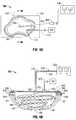
- Wound dressing system 500includes cover layer 150 for covering bed “w,” and a voltage source 530 is positioned within wound bed “w.” As seen in FIG. 5A , voltage source 530 is placed in wound bed “w,” above wound electrode 120 and captured by or beneath layer cover layer 150.
- Voltage source 530provides DC, pulsed DC. AC or any other suitable current, appropriate for a particular patient, to conducting wires 140, 342.
- Voltage source 530may be an electromechanical device controlled by means of embedded software so as to provide a current profile desired by the clinician. This externally applied current mimics and enhances the naturally occurring flow of electrical current generated by the injured bodily tissue, and thus augments the wound healing process.
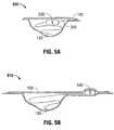
- Wound dressing system 500is substantially similar to wound dressing system 100 and thus will only be discussed in detail herein to the extent necessary to describe the construction and/or use thereof.
- voltage source 530is affixed in the peri-wound region in close proximity to the peri-wound electrode 340 by placing some section of the cover layer above and around it.
- wound electrode 120may act as a positive energy pole and peri-wound electrode 340 may act as a negative energy pole, or vice-versa, to thereby create a current path therebetween and create a therapeutic effect on the surface of wound bed "w" to enhance the healing process thereof.
- the currentmay be continuously applied, applied in pulses, applied for specific periods of time or combination thereof.
- the plurality of hydrogel beadsmay be connected in a strand by a non-conductive wire, filament, line, thread or the like.
- a non-conductive wire, filament, line, thread or the likeBy having a plurality of hydrogel beads that are connected in a strand allows an end user (e.g., surgeon, nurse, etc.) to better pack a wound with a plurality of hydrogel beads and to also allow for the remnants of the plurality of hydrogel beads, following their useful life or some predetermined period of time, to be more easily removed from the wound since the plurality of hydrogel beads arc connected in a strand.
- the present disclosuremay relate to a patient monitoring system which provides enhanced functional capability relative to known systems and provides a wireless communication link between a patient monitoring device, worn by a patient, and a local hub.
- the patient monitoring systemmay be adapted to monitor various patient physiological characteristics.
- the data from the patient monitoring devicemay be wirelessly transmitted to a local hub, which, in turn, is configured to automatically transfer the data to a remote server or computer (e.g., of a clinician), for example, over a public or private communications network.
- a remote server or computere.g., of a clinician
Landscapes
- Health & Medical Sciences (AREA)
- Life Sciences & Earth Sciences (AREA)
- Engineering & Computer Science (AREA)
- Animal Behavior & Ethology (AREA)
- General Health & Medical Sciences (AREA)
- Public Health (AREA)
- Veterinary Medicine (AREA)
- Biomedical Technology (AREA)
- Heart & Thoracic Surgery (AREA)
- Vascular Medicine (AREA)
- Radiology & Medical Imaging (AREA)
- Nuclear Medicine, Radiotherapy & Molecular Imaging (AREA)
- Chemical & Material Sciences (AREA)
- Hematology (AREA)
- Anesthesiology (AREA)
- Dispersion Chemistry (AREA)
- Materials Engineering (AREA)
- Epidemiology (AREA)
- Cell Biology (AREA)
- Orthopedic Medicine & Surgery (AREA)
- Otolaryngology (AREA)
- Media Introduction/Drainage Providing Device (AREA)
- Electrotherapy Devices (AREA)
- External Artificial Organs (AREA)
- Surgical Instruments (AREA)
Description
- The present application claims the benefit of and priority to U.S. Provisional Application Serial No.
61/231,370, filed on August 5, 2009 - The present disclosure generally relates to an apparatus and systems for treating a wound and, more particularly, to a wound dressing system incorporating a plurality of beads, the beads defining an insulated connected elongate member having an embedded electrode therewith.
- Wound closure typically involves the migration of epithelial and subcutaneous tissue adjacent the wound towards the center of the wound until the wound closes. Closure may be difficult with large wounds or wounds that have become infected. In such wounds, a zone of stasis, which is typically an area in which localized swelling of tissue restricts the flow of blood to the tissues) forms near the surface of the wound. Without sufficient blood flow, the epithelial and subcutaneous tissues surrounding the wound not only receive diminished oxygen and nutrients, but, are also less able to successfully fight microbial infection and, thus, are less able to close the wound naturally. Such wounds have presented difficulties to medical personnel for many years.A wound healing device is disclosed in
US2005/0065484 . This device containing a bio-absorbable fabric is placed inside the wound. As the fabric is being absorbed by the tissue, it serves as a frame work for fibroblasts to bridge the gap in the wounded tissue and thereby promote the healing process. - Also, wound dressings have been used in the medical industry to protect and/or facilitate healing of open wounds. One technique has been to use negative pressure therapy, which is also known as suction or vacuum therapy. A variety of negative pressure devices have been developed to allow excess wound fluids, i.e., exudates, to be removed while at the same time isolating the wound to protect the wound and, consequently, effect recovery time. Various wound dressings have been modified to promote the healing of open wounds.
- The present disclosure generally relates to an apparatus for treating an open wound.
- According to an aspect of the present disclosure, a wound dressing system is provided and includes a fluid permeable cover layer configured for positioning across a wound, wherein the cover layer is configured to permit exudates from the wound to pass therethrough; a plurality of beads positionable in the wound and retained within the wound by the cover layer, the beads defining an insulated inter-connected elongate member; and an electrode embedded within and extending through at least a portion of the elongate member. In use, a current generated by an external energy source electrically flows through the electrode.
- The wound dressing system may further include a conduit for supplying reduced pressure to the wound.
- The plurality of beads may be constructed from hydrogel materials. The embedded electrode may extend through an entire length of the elongate member.
- A portion of at least one bead of the plurality of heads may include a conductive coating. The conductive coating may be at least one of Ag, AgCl, Cu. Au, carbon rubber, carbon film, and aluminum film.
- The wound dressing system may further include a peripheral electrode and a rotator in operable communication with the peripheral electrode.
- The wound dressing system may still further include a support layer secured to the peripheral electrode and configured to secure the peripheral electrode in position. The support layer may at least partially overlie the peripheral electrode and may be positioned along a periphery of the wound.
- The wound dressing system may further include a voltage source embedded within the fluid permeable support layer. The voltage source may be positioned at one end of the elongate member. The voltage source may be positioned so as to divide the elongate member into at least two portions.
- Each bead of the plurality of beads may be sufficiently rigid to facilitate passage of the exudates through spaces defined between adjacent beads.
- According to another aspect of the present disclosure, a method of manufacturing a wound dressing configuration is provided. The method can comprise providing a fluid permeable cover layer, wherein the cover layer is configured for positioning across a wound and is configured to permit exudates from the wound to pass therethrough; providing a plurality of beads positionable in the wound, the beads defining an insulated inter-connected elongate member; and providing an electrode embedded within and extending through at least a portion of the elongate member; wherein a current generated by an external energy source electrically flows through the electrode.
- The method may further include supplying reduced pressure to the wound.
- The plurality of beads may be constructed from hydrogel materials. The embedded electrode may extend through an entire length of the elongate member.
- Each bead of the plurality of beads may have a first length; adjacent beads of the plurality of beads may be separated from each other by a second length; and the first length may be greater than the second length.
- A portion of at least one bead of the plurality of beads may include a conductive coating. The conductive coating may be at least one of Ag, AgCl. Cu, Au, carbon rubber, carbon film, and aluminum film.
- The method may further comprise providing a peripheral electrode and a rotator in operable communication with the peripheral electrode. The method may still further comprise providing a cover layer adapted for positioning across the wound to substantially enclose the beads within the wound. The method may further comprise positioning the peripheral electrode at least partially along a periphery of the outer member.
- The method may further include embedding a voltage source within the fluid permeable support layer. The method may include positioning the voltage source at one end of the elongate member. The voltage source may be positioned so as to divide the elongate member into at least two portions.
- The plurality of beads may be sufficiently rigid to facilitate passage of the exudates through spaces defined between adjacent beads.
- According to yet another aspect of the present disclosure, a method of using a wound dressing configuration is provided. The method includes the steps of placing a plurality of hydrogel beads in a wound, the beads (i) defining an insulated inter-connected elongate member and (ii) having an electrode embedded within and extending through at least a portion of the elongate member; placing a peripheral wound electrode on a person; attaching a cover layer over the wound so that the cover layer forms a barrier between the wound and an outside environment; communicating energy to the embedded electrode and the peripheral electrode; and monitoring the energy communicated to the embedded electrode and the peripheral electrode.
- One or more aspects of the invention can be directed to providing an effective electrical stimulation or E-STIM therapy by providing sufficient current flow to the wound bed of the wound dressing system and allow the flow of current throughout the damaged tissue and can enhance or promote wound healing processes. Still further aspects of the invention can provide a system for providing a more consistent and uniform distribution of current to a wound bed of a wound dressing system while maintaining a moist wound environment.
- The accompanying drawings, which are incorporated in and constitute a part of this specification, illustrate embodiments of the disclosure and, together with a general description of the disclosure given above, and the detailed description of the embodiment(s) given below, serve to explain the principles of the disclosure, wherein:
FIG. 1 is a diagram showing a wound dressing system having a bead design including an electrode, in accordance with one or more embodiments of the present invention;FIG. 2 is an enlarged diagram showing an indicated area of detail of the wound dressing system ofFIG. 1 , illustrating a hydrogel bead including a conductive coating, in accordance with one or more embodiments of the present invention;FIG. 3 is a diagram showing a strain relief assembly of the wound dressing system ofFIG. 1 , in accordance with one or more embodiments of the present invention;FIG. 4A is a top, plan view showing a wound dressing system ofFIGS. 1-3 , in accordance with one or more embodiments of the present invention;FIG. 4B is a cross-sectional view showing the wound dressing system ofFIG. 4A , as taken through 4B-4B ofFIG. 4A , in accordance with one or more embodiments of the present invention;FIG. 5A is a side cross-sectional view showing a wound dressing system including a voltage source disposed in a first location, in accordance with one or more embodiments of the present invention; andFIG. 5B is a side cross-sectional view showing a wound dressing system including a voltage source disposed in a second location, in accordance with one or more embodiments of the present invention.- While embodiments of the present disclosure are susceptible to various modifications and alternative constructions, certain illustrated embodiments thereof have been shown in the drawings and will be described below in detail. It should be understood, however, that there is no intention to limit the embodiments of the present disclosure to the specific form disclosed, but, on the contrary, the embodiments are intended to cover all modifications, alternative constructions, and equivalents falling within the scope of the present disclosure as defined in the claims.
- While various embodiments of the invention are described herein, it is to be distinctly understood that this invention is not limited thereto but may be variously embodied to practice within the scope of the following claims. The present invention may be understood more readily by reference to the following detailed description of the invention taken in connection with the accompanying drawing figures, which form a part of this disclosure. It is to be understood that this invention is not limited to the specific devices, methods, conditions or parameters described and/or shown herein, and that the terminology used herein is for the purpose of describing particular embodiments by way of example only and is not intended to be limiting of the claimed invention.
- As used herein, the term "hydrogel" may refer to a wide variety of polymer-based compositions. These materials may be synthesized for example from monomer(s) or from monomer(s) mixed with polymer(s) in water. They may be obtained by chemical modification of existing polymer(s) or by adding water to existing dry polymers. Any biocompatible hydrogel may be utilized in accordance with the present disclosure. Generally speaking, a hydrogel according to the present disclosure may include a coherent, three-dimensional aqueous polymer system capable of imbibing water without liquefying. In embodiments, insolubility in water may be provided by crosslinking the hydrogel polymer. In embodiments, hydrogels or water-containing gels of the present disclosure may include water and various chemical substances.
- The embodiments of the present disclosure further provide a wound dressing system that promotes healing of a wound that may be used in conjunction with negative pressure therapy. One exemplary wound dressing of the system includes a plurality of beads supported by a support layer. The beads conform to the shape of the wound while allowing the air and exudates to flow through the dressing, thereby promoting a moist environment and facilitating healing of the wound. One or more aspects of the invention can be directed to a wound dressing system, comprising a cover layer configured for positioning across a wound; a plurality of beads positionable in the wound and to be retained within the wound by the cover layer, the plurality of beads connected to each other and forming an elongate member; and an electrode embedded within and extending through each of the plurality of beads that form the elongate member; and an external energy source configured to provide a current that electrically flows through the electrode. In some cases, the dressing system consists essentially of a cover layer configured for positioning across a wound; a plurality of beads positionable in the wound and to be retained within the wound by the cover layer, the plurality of beads connected to each other and forming an elongate member; and an electrode embedded within and extending through each of the plurality of beads that form the elongate member; and an external energy source configured to provide a current that electrically flows through the electrode. In other cases, however, the wound dressing system can further comprise a conduit for supplying reduced pressure to the wound. In still other cases, the wound dressing system can further comprise a peripheral electrode and a rotator in operable communication with the peripheral electrode. Each of the plurality of beads can be constructed from or can consist of a hydrogel material. Further aspects of the invention can be directed to a method of manufacturing a wound dressing configuration, comprising providing a cover layer, wherein the cover layer is configured for positioning across a wound, providing a plurality of beads positionable in the wound, the beads serially connected to each other to form an elongate member, and providing an electrode embedded within and extending through each bead of the plurality of beads that form the elongate member, the electrode configured to have a current flow therethrough, providing an external energy source electrically flows through the electrode. In other cases, the method can consist of providing a cover layer, wherein the cover layer is configured for positioning across a wound, providing a plurality of beads positionable in the wound, the beads serially connected to each other to form an elongate member, and providing an electrode embedded within and extending through each bead of the plurality of beads that form the elongate member, the electrode configured to have a current flow therethrough, providing an external energy source electrically flows through the electrode.
- Further embodiments of the present disclosure can be directed to negative pressure wound treatment (NPWT) systems (or apparatus) including a collection canister having a chamber to collect wound fluids. Some embodiments of the presently disclosed NPWT systems are generally suitable for use in applying negative pressure to a wound to facilitate healing of the wound in accordance with various treatment modalities.
- Some advantageous embodiments of the presently disclosed systems and/or components thereof are entirely portable and may be worn or carried by the user such that the user may be completely ambulatory during the therapy period. Still further embodiments of the presently disclosed systems and components thereof may be entirely reusable or may be entirely disposable after a predetermined period of use or may be individually disposable whereby some of the components are reused for a subsequent therapy application.
- Hereinafter, embodiments of the presently disclosed systems and embodiments of the presently disclosed beads for use in the various systems are described with reference to the accompanying drawings. Like reference numerals may refer to similar or identical elements throughout the description of the figures. As used herein, "wound exudate," or, simply, "exudates," generally refers to any fluid output from a wound, e.g., blood, serum, and/or pus, etc. As used herein, "fluid" generally refers to a liquid, a gas or both.
- Embodiments will be described below while referencing the accompanying figures. The accompanying figures are merely examples and arc not intended to limit the scope of the present disclosure.
- Referring now to the drawings wherein like components are designated by like reference numerals throughout the several views, as seen in
FIG. 1 , a wound dressing system, according to an embodiment of the present disclosure, is generally designated as 100. Wound dressing system 100 may be in the form of a beaded design including a plurality ofhydrogel 110 beads (or hydrogel materials 110), awound electrode 120, an insulatingmember 130, and aconducting wire 140.Beads 110 define an inter-connectedelongate member 112 supporting or surrounding an embeddedwound electrode 120.Wound electrode 120 extends the entire length ofelongate member 112. One end ofwound electrode 120 is configured to connect to aconducting wire 140. Conductingwire 140 receives a current from an external energy source (not shown). The external energy source may be any type of energy source contemplated by one skilled in the art, such as, but, not limited to, a battery, fuel cell, generator, and/or hybrid power supply. Additionally, conductingwire 140 is surrounded by an insulatingmember 130.Beads 110 may have a length or diameter L1, andadjacent beads 110 may be separated from each other by a length L2. It is further contemplated that length L1 is greater than length L2. However, any desirable distance/length relationship may be established between lengths L1 and L2 ofadjacent beads 110.Beads 110 may be formed to be substantially rigid so as to maintain their shapes for at least a predetermined period of time during a healing of a wound. In this regard,beads 110 when arranged within a wound bed "w" (shown inFIG. 4B ) define interstitial spaces, pockets, or passages 492 (shown inFIG. 4B ) therebetween to permit wound exudate to pass or migrate throughpassages 492. The sizes or diameters. L1, ofbeads 110 can vary, but they should be sized to achieve a proper pore size through a bead arrangement to facilitate cell proliferation and allow fluid and air to be evacuated from the wound. Porosity in the range of 10-1000 µm has been found beneficial in stimulating cell proliferation and in allowing fluid and air to be evacuated from the wound. As a negative pressure is applied to wound bed "w,"beads 110 may move and readjust their respective positions to prevent painful ingrowth that can occur with current foam designs.Beads 110 may desirably remain substantially rigid for at least a predetermined period of time during healing so as to maintain the desired spacing ofpassages 492 therebetween.Beads 110 may be non-absorbable, partially absorbable or fully absorbable. Ifbeads 110 are formed from an absorbable material, the rate of absorption ofbeads 110 may be selected to maintain the desired rigidity ofbeads 110 during a predetermined period of healing. One skilled in the art may select the materials of fabrication ofbeads 110 to reach these objectives.- The dissolution rate of
beads 110 may be dependent on material selection, bead size (surface area of bead in contact with fluids), amount of fluid in wound bed "w" temperature and exposure to mechanical stress (i.e., compressive forces). Some or all ofbeads 110 could be designed to remain rigid for the entire time that the dressing remains in place on the patient, or from about 1 day to about 1 week or longer. This maintains air and fluid flow away from the wound bed "w." Some ofbeads 110 could be designed to dissolve over this time period, to release any active ingredients or agents incorporated therein. Additional dissolution ofbeads 110 could be timed to coincide with planned dressing changes to limit the potential of tissue growth intobeads 110 and causing trauma upon removal of dressing. Beads 110 may be made from a hydrogel material or the like. The hydrogel may be made from, for example, but not limited to, PROMEON RG-63B hydrogel, available from Tyco Healthcare Group LP d/b/a Covidien, Mansfield, Massachusetts.Beads 110 may be manufactured from a suitable biocompatible material.Beads 110 may be antimicrobial beads, beads with growth factors, medicaments, antibiotics, analgesics, and healing factors such as vitamins, nutrients and the like. Thesebeads 110 are preferably non-adherent and may be bio-absorbable over a predetermined period of time. Acrylic (PMMA) can be used for its clarity and would also provide the ability for the clinician to see the wound without removing the dressing. Other materials that could be used are polycarbonate, polystyrene. PVC. ABS, SAN, glass or silicone. Bio-absorbable polymers could also be used, e.g., polylactide (PLA), polyglycolide (PGA), Chitosan, polyethylene oxide (PEO) or polyethylene glycol (PEG).- Hydrogel is desirably used for
beads 110 as it forms a conductive medium betweenwound electrode 120 and wound bed "w," thus facilitating a flow of current therebetween while maintaining a moist wound environment. In general, hydrogels consist of a hydrophilic network structure retaining high concentrations of water. Moreover, in this application, the hydrogel ofbeads 110 acts as a wound filler material as well since it helps retain and transport exudate coming out of the wound, while providing a conductive path for current flow. - Another example of a composition that can be used in this application is poly(vinyl alcohol) (PVA) since it is biocompatible and can be tailor made to provide good mechanical properties such that it does not disintegrate when placed in the wound. Since hydrogel may also be functioning as a conductive medium, a gel electrolyte may be most desirable. Experimentation with several materials has demonstrated that a poly(ethylene glycol) (PEG):PVA:NH4SCN composite gel electrolyte which has high ionic conductivity would be advantageous. Some other examples of similar gel electrolytes include poly(VC-AN), poly(MMA-VC), poly(styrene-AN), and poly(styrene-butadiene).
- The design of
beads 110 presents many advantages. For example,beads 110 may prevent direct contact of wound bed "w" withwound electrode 120. Eachbead 110 may have a substantially circular/elliptical cross-sectional profile. The arrangement ofbeads 110 ofwound dressing system 100 increases the contact area with wound bed "w," thus enabling the flow of current to a larger area of wound bed "w." This provides a more uniform distribution of current to the wound bed "w," which is one of the challenges in providing effective E-STIM therapy. - The size of
beads 110 may be small cnough such thatmultiple beads 110 would contact the wound bed "w" to achieve this objective. Additionally, the arrangement ofbeads 110 ofwound dressing system 100 may aid in creating interstitial spaces (shown inFIG. 4B ) so as to allow breathability through or aroundwound electrode 120. This can be easily achieved by ensuring length L1 is greater than length L2. The relatively thinner or shorter sections or lengths betweenbeads 110 allow more flexibility aswound electrode 120 is twirled, folded-over, twisted, and placed by, for example, a clinician to fill up the wound. - In one embodiment, a number of
wound electrodes 120 may be positioned or deposited at various preselected locations throughout the length ofelongate member 112 ofbeads 110. Additionally, the length or diameter, L1, ofbeads 110 may be of any size (from a few millimeters to a few inches). Also, the length of abead 110 need not be equal to the diameter of saidbead 110. Wound electrodes 120 may be of any shape or size or width or length depending on the desired application. For example, woundelectrode 120 may be a mesh design that envelops the interior ofbeads 110. In other words, woundelectrode 120 need not be centrally disposed withinbeads 110 ofelongate member 112.Wound electrode 120 may also be of uniform or non-uniform thickness as it extends throughelongate member 112. It is contemplated that, a plurality of electrode placement schemes with more or fewer electrodes in different positions can be used. If a different electrode placement scheme is desired, woundelectrode 120 and peri-wound electrode 340 (seeFIGS. 3 ,4A. and 4B ) can be positioned differently as desired.- In one embodiment, the present disclosure may relate to a patient monitoring system which provides enhanced functional capability relative to known systems and provides a wireless communication link between a patient monitoring device, worn by a patient, and a local hub. The patient monitoring system may be adapted to monitor various patient physiological characteristics. The data from the patient monitoring device may be wirelessly transmitted to a local hub, which, in turn, is configured to automatically transfer the data to a remote server or computer (e.g., of a clinician), for example, over a public or private communications network.
- In one embodiment, wound
electrode 120 may be separately fabricated (as separate units) with respect tobeads 110 and then combined to form a single unit. In an alternate embodiment, woundelectrode 120 may be fabricated withbeads 110 as one unit or component. Several separate or unitary fabrication techniques may be contemplated by one skilled in the art. - Referring now to
FIG. 2 . a diagram of an embodiment of a hydrogel bead including a conductive coating or outer surface, in accordance with the present disclosure is illustrated. - As described above,
bead 110 is made from hydrogel material and includes woundelectrode 120 embedded therein and extending therethrough. Eachbead 110 may include conductive material(s) 114 disposed on an outer surface thereof. Eachbead 110 may be of any uniform or non-uniform shape or size and may be positioned on any portion ofwound electrode 120 depending on the desired application. - In one embodiment, each
bead 110 may include conductive material(s) (e.g. Ag, Ag/AgCl, Cu, Au) coated on at least a portion of the outer surface thereof to enable enhanced current flow to specific parts of wound bed "w" (shown inFIG. 4B ), such as the approximate center of the wound bed "w." - In one embodiment, only a select number of
beads 110 of the total number of beads ofwound dressing system 100 may incorporate aconductive coating 114. Alternatively, allbeads 110 of the plurality of beads may incorporate aconductive coating 114. In additional alternate embodiments, a portion of the surface ofbeads 110 may include one type of conductive coating 114 (e.g., Ag) and another portion of the surface ofbeads 110 may include a different type of conductive coating (e.g., Ag/AgCl). Thus, different combinations ofconductive coatings 114 may be used on the sameelongate member 112 defining a plurality of different beaded segments. - In another embodiment,
conductive coating 114 may at least partially envelop/encompass/engulf the outer surface ofbead 110. As illustrated inFIG. 2 ,conductive coating 114 has a strip shape. However, any uniform or non-uniform shape and/or size or a design/pattern may be contemplated. In an alternate embodiment, a first portion of abead 110 may be fully enveloped by one or moreconductive coatings 114, whereas a second portion ofbead 110 may be partially enveloped by one or moreconductive coatings 114. - Referring now to
FIG. 3 , a strain relief or rotator system, in accordance with the present disclosure is illustrated, and generally designated as 300. Rotator system 300 includes arotator 320, an insulated connecting wire 330 (pig-tailedinsulated conducting wires 140, 342) extending from therotator 320, aperipheral wound electrode 340 extending fromrotator 320, and asupport layer 350 surroundingperipheral wound electrode 340.- Peripheral wound electrode 340 (also referred to herein as "peri-wound electrode") includes an electrode portion or conducting
wire 342 having an insulatingsheath 343 and having the insulatingsupport layer 350 extending along a length thereof.Peri-wound electrode 340 may be available with or without a hydrogel layer between theperi-wound electrode 340 and the skin. The hydrogel layer can enhance contact with intact skin, hence enabling better current flow. Support layer 350 includes an adhesive layer 344 (seeFIG. 4B ) on the bottom surface thereof to allow for easy fixation on the peri-wound area (shown inFIG. 4A ) or around wound bed "w."Support layer 350 is fabricated from an insulation material to help ensure that the current flow is through the tissue.Support layer 350 may be constructed from common materials such as cloth, spun lace, vinyl, tricot, or other materials used to cover layers of common wound dressings such as POLYSKIN II dressing, available from Tyco Healthcare Group LP.- Materials used for
peri-wound electrode 340 may be the same as that used forwound electrode 120. In an embodiment,support layer 350 andperi-wound electrode 340 are combined in the form of a silver printed cloth, which provides excellent current dispersion. - Both wound
electrode 120 andperi-wound electrode 340 may be made out of or comprise materials commonly used for this purpose, e.g., Ag, AgCl, Au, Cu, Carbon Rubber, Carbon film. Aluminum film, and combinations thereof.Electrodes beads 110 and peri-wound electrode 340 (e.g., by coating a silver electrode with AgCl (silver-chloride), or by providing a silver coated carbon electrode, etc.). - Both wound
electrode 120 andperi-wound electrode 340 may be consolidated inside a plastic strain relief 320 (referred herein as "rotator") to enable easy management of dressing when in use.Rotator 320 permits rotational movement, thus providing strain relief and providing an easy means to apply bothelectrodes wires 140 and 342 (one going to eachelectrode wire 330.Connecting wire 330 may extend to a connector 460 (shown inFIG. 4A ) located within or in proximity torotator 320, which enables easy connection and disconnection. Snap features common in medical electrodes, e.g., TENS electrodes, available from Tyco Healthcare Group LP, may be used. Thus, conductingwire 140 leading to woundelectrode 120, and conductingwire 342 leading toperi-wound electrode 340 are electrically insulated from each other. However, in an embodiment,elongate member 112 ofwound electrode 120 is extendable throughrotator 320, is supported on acover layer 150, and surrounded byperi-wound electrode 340. - Referring now to
FIGS. 4A and 4B , a method of using an applyingwound dressing system 100, illustrating a positioning ofwound electrode 120 andperi-wound electrode 340, in accordance with the present disclosure, is exemplarily depicted. - As seen in
FIGS. 4A and 4B , wounddressing system 100 is shown in place in a wound bed "w." Wound bed "w" is circumfcrentially surrounded byperi-wound electrode 340 that is in contact with the tissue of the patient that is surrounding wound bed "w."Support layer 350 may overlieperi-wound electrode 340. Additionally, wound bed "w" is at least partially filled with a length ofwound electrode 120. - As seen in
FIGS. 4A and 4B , wounddressing system 100 includescover layer 150 covering/isolating wound bed "w."Wound electrode 120 ofsystem 100 is positioned within wound bed "w" andperi-wound electrode 340 ofsystem 100 is positioned on the outer circumference or along an outer periphery of wound bed "w."Cover layer 150 is sized to overlie wound bed "w" andperi-wound electrode 340.Rotator 320 is supported bycover layer 150 to permit passage ofwound electrode 120 into wound bed "w." Wound bed "w" is filled with would electrode 120 such that woundelectrode 120 sits on the surface of wound bed "w," andbeads 110 are arranged within wound bed "w," to define spaces orpassages 492 therebetween to permit wound exudate to pass throughpassages 492. Cover layer 150 is adapted to substantially overlie and enclose or cap wound bed "w," as shown inFIG. 4B . In an embodiment, it is contemplated thatcover layer 150 may be substantially porous to permit exudates to pass from the wound bed "w" throughcover layer 150. "Porous" as used herein refers to a material which contains numerous small perforations or pores which allow wound fluids of all kinds to pass through the material.Cover layer 150 may also be non-adherent. "Non-adherent" as used herein refers to a material that does not adhere to tissues in and around wound bed "w." This configuration allows fluid and exudates to flow uninhibited through the entire surface ofcover layer 150 with minimal "sticking" ofcover layer 150 to wound bed "w" thereby permitting a vacuum to be delivered over the entire surface ofcover layer 150.- The passage of wound exudates through
cover layer 150 is preferably unidirectional such that wound exudates do not flow back into wound bed "w." This unidirectional flow feature could be in the form of directional apertures imparted into the material layer, a lamination of materials of different absorption to coverlayer 150 or specific material selection that encourages directional flow. However, a bidirectional layer for the purposes of supplying medicine or anti-infectives to wound bed "w" is also envisioned. - The sealing mechanism, for sealing or adhering
cover layer 150 around wound bed "w," may be any adhesive applied to the tissue that surrounds wound bed "w." The adhesive should provide acceptable adhesion to the tissue surrounding wound bed "w," e.g., the peri-wound area, and be acceptable for use on the skin without contact deteriorization (e.g., the adhesive should preferably be non-irritating and non-sensitizing). The adhesive may be permeable to permit the contacted skin to breathe and transmit moisture. Additionally, the adhesive could be activated or de-activated by an external stimulus such as heat or a given fluid solution or chemical reaction. Adhesives include, for example, medical grade acrylics like the adhesive used with CURAFOAM ISLAND™ dressing of Tyco HealthCare Group LP d/b/a Covidien, or any silicone or rubber based medical adhesives that are skin friendly and non-irritating. Cover layer 150 may typically be a flexible material, e.g., resilient or elastomeric, that seals the top of wound bed "w." Exemplary flexible materials include the transparent dressing manufactured under the trademark POLYSKIN II by Tyco Healthcare Group LP. Preferably,cover layer 150 is transparent and provides a barrier to microbes and fluid containment.Cover layer 150 may be manufactured from a permeable plastic film providing it with a high moisture vapor transmission rate (MVTR) to allow the passage of exudates through the film. Such films could be manufactured from polyurethanes, breathable polyolefins, or copolyesters. The transparency ofcover layer 150 permits a visual review of the status of the healing of wound "w." Alternatively,cover layer 150 may be impermeable to moisture vapors.- In use,
beads 110 ofwound electrode 120, disposed within wound bed "w" arrange themselves to conform to the shape of wound bed "w." In particular,beads 110 migrate into remote areas of the wound, i.e., "tunnel" into wound "w" as shown inFIG. 4B .Cover layer 150 is placed in contact with peripheral skin of the patient and may be secured thereto adhesives or the like. As seen inFIGS. 4A and 4B , avacuum connector 170 may then be secured to coverlayer 150 and aconduit 172 may then be connected tovacuum connector 170. A negative pressure source "VS" may then be activated, thus creating a reduced pressure state within wound bed "w." As the pumping progresses,beads 110 maintain their shape thereby creating and/or maintainingpassageways 492 for the wound exudates to flow out of wound bed "w." - In further use,
beads 110 ofwound electrode 120 may be configured such that it enables easy application because of the flexible electrode configuration. It is intended that, for example, the clinician first placesbeads 110 ofwound electrode 120 in wound bed "w" by twirling, twisting, or folding the same in order to fill wound bed "w." Gauze dipped in saline (e.g., KERLIX AMD dressing available from Tyco Healthcare Group LP) can also be placed in wound bed "w" between layers ofbeads 110 to help manage and transport exudates. - Following filling of wound bed "w" with
wound electrode 120, the clinician can placeperi-wound electrode 340 around wound bed "w."Peri-wound electrode 340 is placed by peeling off a covering layer to expose an adhesive layer 344 (which is on the bottom side of support layer 350) and using it to affixperi-wound electrode 340 to intact skin of a patient. Sinceperi-wound electrode 340 is preferably flexible, the user can applyperi-wound electrode 340 such that it follows the peripheral contours of wound bed "w." Wound electrode 120 andperi-wound electrode 340 do not need to be pre-cut into various shapes because bothelectrodes wound electrode 120 that requires management by a clinician is the electrode length. If either wound orperi-wound electrode - Additionally,
cover layer 150 is attached over wound bed "w" using anadhesive layer 344 so that it forms a barrier between wound bed "w" and an outside environment.Cover layer 150 can also extend oversupport layer 350 that was used to affixperi-wound electrode 340, hence reducing the possibility ofsupport layer 350 peeling away. Ascover layer 150 is being placed over wound bed "w," the clinician ensures that conductingwire 140 ofwound electrode 120 comes out of wound bed "w" throughrotator system 300 so as to allow communication with a voltage source (described with reference toFIGS. 5A and 5B ). - With
wound dressing system 100 in position as described above, a clinician activatesvoltage source 530 and vacuum source to a predetermined treatment setting. Whenvoltage source 530 is activated, electrical current is delivered fromvoltage source 530 to woundelectrode 120. into the tissue defining wound bed "w," toperi-wound electrode 340 and back tovoltage source 530, and/or vice-versa depending on the setting. In this manner, an electrical circuit is formed to circulate electrical current (as indicated by arrows "F" ofFIG. 4B ) through the tissue defining wound bed "w" and thereby aid in the treatment/healing thereof. - Referring now to
FIG. 5A , a method of using and applyingwound electrode 120 and wounddressing system 100, illustrating a positioning of avoltage source 530, in accordance with the present disclosure is exemplarily depicted.Wound dressing system 500 is substantially similar to wound dressingsystem 100 and thus will only be discussed in detail herein to the extent necessary to describe the construction and/or use thereof. Wound dressing system 500 includescover layer 150 for covering bed "w," and avoltage source 530 is positioned within wound bed "w." As seen inFIG. 5A ,voltage source 530 is placed in wound bed "w," abovewound electrode 120 and captured by or beneathlayer cover layer 150.- The connecting or conducting
wires wound electrode 120 andperi-wound electrode 340, respectively, forming connectingwire 330 and coming out ofrotator 320 arc connected tovoltage source 530 by asuitable connector 460.Voltage source 530 provides DC, pulsed DC. AC or any other suitable current, appropriate for a particular patient, to conductingwires Voltage source 530 may be an electromechanical device controlled by means of embedded software so as to provide a current profile desired by the clinician. This externally applied current mimics and enhances the naturally occurring flow of electrical current generated by the injured bodily tissue, and thus augments the wound healing process. - Referring now to
FIG. 5B , a method of using and applyingwound electrode 120 and wounddressing system 100, illustrating a positioning of avoltage source 530, in accordance with the present disclosure is exemplarily depicted.Wound dressing system 500 is substantially similar to wound dressingsystem 100 and thus will only be discussed in detail herein to the extent necessary to describe the construction and/or use thereof. - In the embodiment of
FIG. 5B ,voltage source 530 is affixed in the peri-wound region in close proximity to theperi-wound electrode 340 by placing some section of the cover layer above and around it. - It is contemplated that
wound electrode 120 may act as a positive energy pole andperi-wound electrode 340 may act as a negative energy pole, or vice-versa, to thereby create a current path therebetween and create a therapeutic effect on the surface of wound bed "w" to enhance the healing process thereof. It is envisioned that the current may be continuously applied, applied in pulses, applied for specific periods of time or combination thereof. - In accordance with an aspect of the present disclosure, it is envisioned that the plurality of hydrogel beads may be connected in a strand by a non-conductive wire, filament, line, thread or the like. By having a plurality of hydrogel beads that are connected in a strand allows an end user (e.g., surgeon, nurse, etc.) to better pack a wound with a plurality of hydrogel beads and to also allow for the remnants of the plurality of hydrogel beads, following their useful life or some predetermined period of time, to be more easily removed from the wound since the plurality of hydrogel beads arc connected in a strand.
- In any of the preceding embodiments described herein, the present disclosure may relate to a patient monitoring system which provides enhanced functional capability relative to known systems and provides a wireless communication link between a patient monitoring device, worn by a patient, and a local hub. The patient monitoring system may be adapted to monitor various patient physiological characteristics. The data from the patient monitoring device may be wirelessly transmitted to a local hub, which, in turn, is configured to automatically transfer the data to a remote server or computer (e.g., of a clinician), for example, over a public or private communications network.
- It is to be understood that the illustrated embodiments are for the purpose of example, and that numerous other configurations of wound dressing systems having a plurality of beads exist. Accordingly, the illustrated and described embodiments are not intended to limit the scope of the inventive subject matter only to those embodiments.
- Although the illustrative embodiments of the present disclosure have been described herein with reference to the accompanying drawings, it is to be understood that the disclosure is not limited to those precise embodiments, and that various other changes and modifications may be effected therein by one skilled in the art.
- Those skilled in the art, having the benefit of the teachings of the present invention as herein and above set forth, may effect modifications thereto. Such modifications are to be construed as lying within the scope of the present invention, as defined by the appended claims.
- Although specific features of the wound dressing system are shown in some of the drawings and not in others, this is for convenience only as each feature may be combined with any or all of the other features in accordance with the aspects of the present disclosure. Other embodiments will occur to those skilled in the art and are within the following claims.
Claims (16)
- A wound dressing system(100), characterized by,
a cover layer(150) configured for positioning across a wound;
a plurality of beads(110) positionable in the wound and to be retained within the wound by the cover layer, the plurality of beads connected to each other and forming an elongate member(112);
an electrode(120) embedded within and extending through each of the plurality of beads that form the elongate member; and
an external energy source(530) configured to provide a current that electrically flows through the electrode. - The wound dressing system according to claim 1, further comprising a conduit(172) for supplying reduced pressure to the wound.
- The wound dressing system according to claim 1, wherein each of the plurality of beads(110) is constructed from a hydrogel material.
- The wound dressing system according to claim 1,
wherein each bead of the plurality of beads has a first length(L1);
wherein adjacent beads of the plurality of beads are separated from each other by a second length(L2); and
wherein the first length is greater than the second length. - The wound dressing system according to claim 1, wherein a portion of at least one bead of the plurality of beads includes a conductive coating(114).
- The wound dressing system according to claim 5, wherein the conductive coating (114) is selected from the group consisting of a silver, silver/silver chloride, copper, gold, carbon rubber, carbon film, aluminum film, and combinations thereof
- The wound dressing system according to claim 1, further comprising a peripheral electrode(340) and a rotator(320) in operable communication with the peripheral electrode.
- The wound dressing system according to claim 7, further comprising a support layer(350) secured to the peripheral electrode(340) and configured to secure the peripheral electrode in position, wherein the support layer at least partially overlies the peripheral electrode and is positioned along a periphery of the wound.
- The wound dressing system according to claim 1, further comprising a voltage source(530, V) embedded within the cover layer.
- The wound dressing system according to claim 9, wherein the voltage source(530, V) is positioned at one end of the elongate member or positioned so as to divide the elongate member(112) into at least two portions.
- A method of manufacturing a wound dressing configuration(100), characterized by,
providing a cover layer(150), wherein the cover layer is configured for positioning across a wound;
providing a plurality of beads(110) positionable in the wound, the beads serially connected to each other to form an elongate member(112); and
providing an electrode(120) embedded within and extending through each bead of the plurality of beads that form the elongate member, the electrode configured to have a current flow therethrough;
providing an external energy source(530) for supplying electrical current through the electrode(120). - The method according to claim 11, further comprising supplying a conduit(172) coupled to a source of reduced pressure(VS).
- The method according to claim 11, wherein the plurality of beads are constructed from hydrogel materials.
- The method according to claim 11, wherein each bead of the plurality of beads has a first length (L1), wherein adjacent beads of the plurality of beads are separated from each other by a second length (L2); and wherein the first length is greater than the second length.
- The method according to claim 11, wherein a portion of at least one bead(110) of the plurality of beads includes a conductive coating(114) selected from the group consisting of a silver, silver/silver chloride, copper, gold, carbon rubber, carbon film, aluminum film, and combinations thereof.
- The method according to claim 11, further comprising providing a voltage source(530, V) configured to be embedded under the cover layer(150), wherein the voltage source is positionable at one end of the elongate member(112) or is positionable so as to divide the elongate member into at least two portions.
Applications Claiming Priority (2)
| Application Number | Priority Date | Filing Date | Title |
|---|---|---|---|
| US23137009P | 2009-08-05 | 2009-08-05 | |
| PCT/US2010/044497WO2011017489A1 (en) | 2009-08-05 | 2010-08-05 | Surgical wound dressing incorporating connected hydrogel beads having an embedded electrode therein |
Publications (3)
| Publication Number | Publication Date |
|---|---|
| EP2461863A1 EP2461863A1 (en) | 2012-06-13 |
| EP2461863A4 EP2461863A4 (en) | 2013-01-23 |
| EP2461863B1true EP2461863B1 (en) | 2016-07-27 |
Family
ID=43535374
Family Applications (1)
| Application Number | Title | Priority Date | Filing Date |
|---|---|---|---|
| EP10807136.6AActiveEP2461863B1 (en) | 2009-08-05 | 2010-08-05 | Surgical wound dressing incorporating connected hydrogel beads having an embedded electrode therein |
Country Status (6)
| Country | Link |
|---|---|
| US (2) | US8900217B2 (en) |
| EP (1) | EP2461863B1 (en) |
| JP (1) | JP5281715B2 (en) |
| BR (1) | BR112012008087A2 (en) |
| CA (1) | CA2770182C (en) |
| WO (1) | WO2011017489A1 (en) |
Families Citing this family (23)
| Publication number | Priority date | Publication date | Assignee | Title |
|---|---|---|---|---|
| WO2009140376A1 (en)* | 2008-05-13 | 2009-11-19 | Kci Licensing, Inc. | Catheter/filament style device and methods for treatment of wounds beneath the surface of the skin |
| EP2461863B1 (en) | 2009-08-05 | 2016-07-27 | Covidien LP | Surgical wound dressing incorporating connected hydrogel beads having an embedded electrode therein |
| US8795257B2 (en)* | 2010-07-19 | 2014-08-05 | Kci Licensing, Inc. | Systems and methods for electrically detecting the presence of exudate in dressings |
| DE102010053213B4 (en)* | 2010-12-03 | 2014-10-30 | Gerromed Pflege- Und Medizintechnik Gmbh | Wound dressing for electrostimulation and method for producing such a wound dressing |
| KR101286272B1 (en)* | 2011-07-20 | 2013-07-15 | (재)예수병원유지재단 | Medical Device |
| US10158928B2 (en) | 2012-04-12 | 2018-12-18 | Elwha Llc | Appurtenances for reporting information regarding wound dressings |
| US10130518B2 (en) | 2012-04-12 | 2018-11-20 | Elwha Llc | Appurtenances including sensors for reporting information regarding wound dressings |
| US10226212B2 (en)* | 2012-04-12 | 2019-03-12 | Elwha Llc | Appurtenances to cavity wound dressings |
| US10265219B2 (en) | 2012-04-12 | 2019-04-23 | Elwha Llc | Wound dressing monitoring systems including appurtenances for wound dressings |
| CA2888241C (en)* | 2012-10-16 | 2020-12-29 | Surmodics, Inc. | Wound packing device and methods |
| EP2759310B2 (en) | 2013-01-28 | 2023-11-08 | Mölnlycke Health Care AB | Suction device |
| MX2015015153A (en)* | 2013-05-02 | 2016-08-11 | Vomaris Innovations Inc | Methods and devices for cellular activation. |
| KR102211335B1 (en) | 2013-12-20 | 2021-02-03 | 마이크로벤션, 인코포레이티드 | Device delivery system |
| GB2524777A (en)* | 2014-04-02 | 2015-10-07 | Microarray Ltd | Dressing comprising electrodes |
| US10201457B2 (en) | 2014-08-01 | 2019-02-12 | Surmodics, Inc. | Wound packing device with nanotextured surface |
| US9592160B2 (en) | 2014-09-16 | 2017-03-14 | Garwood Medical Devices, Llc | Wound care bandage and method of wound healing |
| US9789303B2 (en)* | 2014-12-17 | 2017-10-17 | Morton M. Mower | Method and apparatus for improved wound healing |
| WO2017119996A1 (en)* | 2016-01-06 | 2017-07-13 | Kci Liecensing, Inc. | System and methods for the treatment of wounds with dressing having closed cells |
| US10751212B2 (en)* | 2017-06-26 | 2020-08-25 | Maryam Raza | Multilayer dressing device and method for preventing and treating pressure ulcers and chronic wounds |
| CN110368583B (en)* | 2019-06-26 | 2025-03-11 | 龙丹 | A drug line drainage treatment device |
| WO2021038403A1 (en) | 2019-08-30 | 2021-03-04 | DePuy Synthes Products, Inc. | Electrical device for monitoring, prevention, and treatment of implant infections |
| CN112107793B (en)* | 2020-09-27 | 2024-08-09 | 长沙海润生物技术有限公司 | Electric field treatment device for promoting wound healing |
| US20250195196A1 (en)* | 2023-12-18 | 2025-06-19 | Nedeljko Vladimira Gvozdic | Physiologically and mechanically biocompatible artificial pancreas and physically crosslinked polyvinyl alcohol hydrogels and solids from which the bioartificial pancreas is manufactured |
Family Cites Families (147)
| Publication number | Priority date | Publication date | Assignee | Title |
|---|---|---|---|---|
| US3095877A (en)* | 1961-05-01 | 1963-07-02 | Robert L Rowan | Surgical packing |
| DE3217109A1 (en)* | 1982-05-07 | 1983-11-10 | Anton Dr. 4400 Münster Härle | SURGICAL TOOL |
| US4490005A (en)* | 1982-06-21 | 1984-12-25 | Minnesota Mining And Manufacturing Company | Electrical connector |
| GB8419745D0 (en)* | 1984-08-02 | 1984-09-05 | Smith & Nephew Ass | Wound dressing |
| JPS63229068A (en)* | 1987-03-17 | 1988-09-22 | 新技術事業団 | Electrical stimulation wound therapy device |
| US5176663A (en)* | 1987-12-02 | 1993-01-05 | Pal Svedman | Dressing having pad with compressibility limiting elements |
| US5374261A (en)* | 1990-07-24 | 1994-12-20 | Yoon; Inbae | Multifunctional devices for use in endoscopic surgical procedures and methods-therefor |
| US5451204A (en)* | 1988-07-22 | 1995-09-19 | Yoon; Inbae | Multifunctional devices for endoscopic surgical procedures |
| US4969880A (en) | 1989-04-03 | 1990-11-13 | Zamierowski David S | Wound dressing and treatment method |
| US5261893A (en) | 1989-04-03 | 1993-11-16 | Zamierowski David S | Fastening system and method |
| US5527293A (en)* | 1989-04-03 | 1996-06-18 | Kinetic Concepts, Inc. | Fastening system and method |
| US5100396A (en)* | 1989-04-03 | 1992-03-31 | Zamierowski David S | Fluidic connection system and method |
| US5106629A (en)* | 1989-10-20 | 1992-04-21 | Ndm Acquisition Corp. | Transparent hydrogel wound dressing |
| US5158537A (en)* | 1990-10-29 | 1992-10-27 | Alza Corporation | Iontophoretic delivery device and method of hydrating same |
| US5141503A (en)* | 1991-01-29 | 1992-08-25 | Sewell Jr Frank K | Wound suction drainage system |
| US5405317A (en)* | 1991-05-03 | 1995-04-11 | Alza Corporation | Iontophoretic delivery device |
| US5636643A (en) | 1991-11-14 | 1997-06-10 | Wake Forest University | Wound treatment employing reduced pressure |
| US7198046B1 (en)* | 1991-11-14 | 2007-04-03 | Wake Forest University Health Sciences | Wound treatment employing reduced pressure |
| US5645081A (en)* | 1991-11-14 | 1997-07-08 | Wake Forest University | Method of treating tissue damage and apparatus for same |
| US7117868B1 (en) | 1992-05-29 | 2006-10-10 | 3M Innovative Properties Company | Fibrous filtration face mask having a new unidirectional fluid valve |
| GB9212303D0 (en)* | 1992-06-10 | 1992-07-22 | Johnson & Johnson Medical Ltd | Absorbent products |
| US5678564A (en)* | 1992-08-07 | 1997-10-21 | Bristol Myers Squibb | Liquid removal system |
| US5549584A (en) | 1994-02-14 | 1996-08-27 | The Kendall Company | Apparatus for removing fluid from a wound |
| US5701917A (en) | 1994-03-30 | 1997-12-30 | Khouri Biomedical Research, Inc. | Method and apparatus for promoting soft tissue enlargement and wound healing |
| DE69505545T2 (en) | 1994-08-22 | 1999-03-11 | Kinetic Concepts Inc | WOUND DRAINAGE DEVICE |
| DE4433450A1 (en)* | 1994-09-20 | 1996-03-21 | Wim Dr Med Fleischmann | Device for sealing a wound area |
| US6261276B1 (en)* | 1995-03-13 | 2001-07-17 | I.S.I. International, Inc. | Apparatus for draining surgical wounds |
| DE19517699C2 (en)* | 1995-05-13 | 1999-11-04 | Wilhelm Fleischmann | Device for vacuum sealing a wound |
| US5814094A (en)* | 1996-03-28 | 1998-09-29 | Becker; Robert O. | Iontopheretic system for stimulation of tissue healing and regeneration |
| GB9523253D0 (en) | 1995-11-14 | 1996-01-17 | Mediscus Prod Ltd | Portable wound treatment apparatus |
| DE19606490A1 (en)* | 1996-02-22 | 1997-08-28 | Merck Patent Gmbh | Device for the manual production of pearl cord-shaped pharmaceutical implants |
| US5756127A (en)* | 1996-10-29 | 1998-05-26 | Wright Medical Technology, Inc. | Implantable bioresorbable string of calcium sulfate beads |
| US7759538B2 (en)* | 1997-05-27 | 2010-07-20 | Wilhelm Fleischmann | Process and device for application of active substances to a wound surface |
| DE19722075C1 (en)* | 1997-05-27 | 1998-10-01 | Wilhelm Dr Med Fleischmann | Medication supply to open wounds |
| NL1006457C2 (en)* | 1997-07-03 | 1999-01-05 | Polymedics N V | Drainage system to be used with an open wound, element used for applying a drainage pipe or hose and method for applying the drainage system. |
| US7214202B1 (en)* | 1997-07-28 | 2007-05-08 | Kci Licensing, Inc. | Therapeutic apparatus for treating ulcers |
| US6135116A (en)* | 1997-07-28 | 2000-10-24 | Kci Licensing, Inc. | Therapeutic method for treating ulcers |
| GB9719520D0 (en) | 1997-09-12 | 1997-11-19 | Kci Medical Ltd | Surgical drape and suction heads for wound treatment |
| US6071267A (en)* | 1998-02-06 | 2000-06-06 | Kinetic Concepts, Inc. | Medical patient fluid management interface system and method |
| US5974344A (en)* | 1998-03-02 | 1999-10-26 | Shoemaker, Ii; Charles | Wound care electrode |
| JPH11349132A (en)* | 1998-06-08 | 1999-12-21 | Nippon Lsi Card Co Ltd | Article carrier method, distribution system and carrier bag used for them |
| US6458109B1 (en) | 1998-08-07 | 2002-10-01 | Hill-Rom Services, Inc. | Wound treatment apparatus |
| US20010016577A1 (en)* | 1998-08-24 | 2001-08-23 | Douglas Joseph Dobrozsi | Oral mucoadhesive compositions containing gastrointestinal actives |
| US6325788B1 (en)* | 1998-09-16 | 2001-12-04 | Mckay Douglas William | Treatment of wound or joint for relief of pain and promotion of healing |
| US6235788B1 (en)* | 1998-09-21 | 2001-05-22 | James M. Terry | Method for treating pre-malignant basal and squamous cell lesions of the epithelium |
| US6488643B1 (en) | 1998-10-08 | 2002-12-03 | Kci Licensing, Inc. | Wound healing foot wrap |
| GB9822341D0 (en) | 1998-10-13 | 1998-12-09 | Kci Medical Ltd | Negative pressure therapy using wall suction |
| US6767334B1 (en)* | 1998-12-23 | 2004-07-27 | Kci Licensing, Inc. | Method and apparatus for wound treatment |
| PT1164986E (en)* | 1999-04-02 | 2007-01-31 | Kci Licensing Inc | Vacuum assisted closure system with heating and cooling provision |
| US6856821B2 (en)* | 2000-05-26 | 2005-02-15 | Kci Licensing, Inc. | System for combined transcutaneous blood gas monitoring and vacuum assisted wound closure |
| US6994702B1 (en)* | 1999-04-06 | 2006-02-07 | Kci Licensing, Inc. | Vacuum assisted closure pad with adaptation for phototherapy |
| US7799004B2 (en)* | 2001-03-05 | 2010-09-21 | Kci Licensing, Inc. | Negative pressure wound treatment apparatus and infection identification system and method |
| US6695823B1 (en) | 1999-04-09 | 2004-02-24 | Kci Licensing, Inc. | Wound therapy device |
| WO2000072781A2 (en)* | 1999-06-02 | 2000-12-07 | Sethel Interventional, Inc. | Intracorporeal occlusive device |
| US6573409B1 (en)* | 1999-07-02 | 2003-06-03 | The Nutrasweet Company | Process for the preparation of 3,3-dimethylbutanal |
| US6557704B1 (en)* | 1999-09-08 | 2003-05-06 | Kci Licensing, Inc. | Arrangement for portable pumping unit |
| US6238403B1 (en)* | 1999-10-04 | 2001-05-29 | Microvention, Inc. | Filamentous embolic device with expansible elements |
| JP4681185B2 (en)* | 1999-11-29 | 2011-05-11 | ケーシーアイ メディカル リソーシーズ | Trauma treatment device |
| US6824533B2 (en) | 2000-11-29 | 2004-11-30 | Hill-Rom Services, Inc. | Wound treatment apparatus |
| US6764462B2 (en)* | 2000-11-29 | 2004-07-20 | Hill-Rom Services Inc. | Wound treatment apparatus |
| US6522918B1 (en)* | 2000-02-09 | 2003-02-18 | William E. Crisp | Electrolytic device |
| GB2359755A (en)* | 2000-03-03 | 2001-09-05 | Mediplus Ltd | Apparatus for assisting wound healing |
| WO2001064258A1 (en)* | 2000-03-03 | 2001-09-07 | Syntacoll Ag | Agent for the treatment of wounds |
| US8024048B2 (en)* | 2000-03-13 | 2011-09-20 | Ionix Medical Inc. | Method and device for treating cancer with electrical therapy in conjunction with chemotherapeutic agents and radiation therapy |
| GB0011202D0 (en)* | 2000-05-09 | 2000-06-28 | Kci Licensing Inc | Abdominal wound dressing |
| US20010043943A1 (en) | 2000-05-22 | 2001-11-22 | Coffey Arthur C. | Combination SIS and vacuum bandage and method |
| US6530934B1 (en)* | 2000-06-06 | 2003-03-11 | Sarcos Lc | Embolic device composed of a linear sequence of miniature beads |
| US6520982B1 (en)* | 2000-06-08 | 2003-02-18 | Kci Licensing, Inc. | Localized liquid therapy and thermotherapy device |
| US6685681B2 (en)* | 2000-11-29 | 2004-02-03 | Hill-Rom Services, Inc. | Vacuum therapy and cleansing dressing for wounds |
| US6855135B2 (en)* | 2000-11-29 | 2005-02-15 | Hill-Rom Services, Inc. | Vacuum therapy and cleansing dressing for wounds |
| US20020151836A1 (en)* | 2001-02-01 | 2002-10-17 | Burden Bill E. | Portable aspirating and irrigating apparatus and method |
| US7070584B2 (en)* | 2001-02-20 | 2006-07-04 | Kci Licensing, Inc. | Biocompatible wound dressing |
| US6695824B2 (en)* | 2001-04-16 | 2004-02-24 | The United States Of America As Represented By The Secretary Of The Army | Wound dressing system |
| US7645269B2 (en)* | 2001-04-30 | 2010-01-12 | Kci Licensing, Inc. | Gradient wound treatment system and method |
| US7108683B2 (en)* | 2001-04-30 | 2006-09-19 | Kci Licensing, Inc | Wound therapy and tissue management system and method with fluid differentiation |
| US6631294B2 (en)* | 2001-06-01 | 2003-10-07 | Biofisica, Llc | Apparatus and methods for facilitating wound healing |
| US6692510B2 (en)* | 2001-06-14 | 2004-02-17 | Cordis Neurovascular, Inc. | Aneurysm embolization device and deployment system |
| US20030006319A1 (en)* | 2001-06-25 | 2003-01-09 | Silverstein Leonard A. | Thrower system |
| JP2004534595A (en) | 2001-07-12 | 2004-11-18 | ヒル−ロム サービシズ,インコーポレイテッド | Control of vacuum rate of change |
| US7004915B2 (en)* | 2001-08-24 | 2006-02-28 | Kci Licensing, Inc. | Negative pressure assisted tissue treatment system |
| WO2003030966A1 (en) | 2001-10-11 | 2003-04-17 | Hill-Rom Services, Inc. | Waste container for negative pressure therapy |
| US6648862B2 (en) | 2001-11-20 | 2003-11-18 | Spheric Products, Ltd. | Personally portable vacuum desiccator |
| EP1461113A4 (en) | 2001-12-26 | 2009-05-06 | Hill Rom Services Inc | Wound vacuum therapy dressing kit |
| AU2002359828A1 (en)* | 2001-12-26 | 2003-07-24 | Hill-Rom Services Inc. | Vented vacuum bandage and method |
| AU2002359829A1 (en) | 2001-12-26 | 2003-07-24 | Hill-Rom Services, Inc. | Vacuum bandage packing |
| US6999821B2 (en)* | 2002-01-18 | 2006-02-14 | Pacesetter, Inc. | Body implantable lead including one or more conductive polymer electrodes and methods for fabricating same |
| US20030219469A1 (en) | 2002-02-11 | 2003-11-27 | Kci Licensing, Inc. | Environmental control device for tissue treatment |
| EP1487390A4 (en) | 2002-03-07 | 2007-02-21 | Univ Texas | ADAPTABLE BI-LAMINE COMPRESSOR PLANT AND METHOD OF USE |
| US6942633B2 (en)* | 2002-03-22 | 2005-09-13 | Twin Star Medical, Inc. | System for treating tissue swelling |
| US8168848B2 (en) | 2002-04-10 | 2012-05-01 | KCI Medical Resources, Inc. | Access openings in vacuum bandage |
| EP1515775A4 (en)* | 2002-05-07 | 2010-03-03 | Oncostim Inc | Method and device for treating concer with electrical therapy in conjunction with chemotherapeutic agents and radiation therapy |
| US20030212357A1 (en) | 2002-05-10 | 2003-11-13 | Pace Edgar Alan | Method and apparatus for treating wounds with oxygen and reduced pressure |
| EP2650028B1 (en) | 2002-05-31 | 2017-08-09 | KCI Medical Resources | Wound treatment apparatus |
| US7381211B2 (en)* | 2002-08-21 | 2008-06-03 | Kci Licensing, Inc. | Medical closure screen device and method |
| JP2005536275A (en)* | 2002-08-21 | 2005-12-02 | ヒル−ロム サービシズ,インコーポレイテッド | Wound packing to prevent wound closure |
| US20040122434A1 (en)* | 2002-08-23 | 2004-06-24 | Argenta Louis C. | Bone treatment employing reduced pressure |
| US20040039391A1 (en)* | 2002-08-23 | 2004-02-26 | Argenta Louis C. | Bone treatment employing reduced pressure |
| US7846141B2 (en)* | 2002-09-03 | 2010-12-07 | Bluesky Medical Group Incorporated | Reduced pressure treatment system |
| US6979324B2 (en) | 2002-09-13 | 2005-12-27 | Neogen Technologies, Inc. | Closed wound drainage system |
| US7520872B2 (en)* | 2002-09-13 | 2009-04-21 | Neogen Technologies, Inc. | Closed wound drainage system |
| US7625362B2 (en)* | 2003-09-16 | 2009-12-01 | Boehringer Technologies, L.P. | Apparatus and method for suction-assisted wound healing |
| US7815616B2 (en)* | 2002-09-16 | 2010-10-19 | Boehringer Technologies, L.P. | Device for treating a wound |
| SI21299A (en) | 2002-10-21 | 2004-04-30 | Jo�e Jelenc | Device with vacuum bag pressure therapy |
| ES2328908T3 (en)* | 2002-11-07 | 2009-11-19 | Rolf Weidenhagen | ENDOSCOPIC SYSTEM FOR THE TREATMENT OF WOUNDS. |
| US6951553B2 (en) | 2002-12-31 | 2005-10-04 | Kci Licensing, Inc | Tissue closure treatment system and method with externally-applied patient interface |
| US7976519B2 (en)* | 2002-12-31 | 2011-07-12 | Kci Licensing, Inc. | Externally-applied patient interface system and method |
| US7177705B2 (en)* | 2003-02-19 | 2007-02-13 | Stimu-Heal Inc. | Surface electrode for electrical stimulation of tissue |
| US7479133B2 (en)* | 2003-06-30 | 2009-01-20 | Johnson & Johnson Consumer Companies, Inc. | Methods of treating acne and rosacea with galvanic generated electricity |
| US7476222B2 (en)* | 2003-06-30 | 2009-01-13 | Johnson & Johnson Consumer Companies, Inc. | Methods of reducing the appearance of pigmentation with galvanic generated electricity |
| US8734421B2 (en)* | 2003-06-30 | 2014-05-27 | Johnson & Johnson Consumer Companies, Inc. | Methods of treating pores on the skin with electricity |
| CN1822874B (en) | 2003-07-22 | 2010-10-13 | 凯希特许有限公司 | Negative pressure wound treatment dressing |
| US20050065484A1 (en)* | 2003-09-10 | 2005-03-24 | Watson Richard L. | Wound healing apparatus with bioabsorbable material and suction tubes |
| US7128735B2 (en) | 2004-01-02 | 2006-10-31 | Richard Scott Weston | Reduced pressure wound treatment appliance |
| US8062272B2 (en) | 2004-05-21 | 2011-11-22 | Bluesky Medical Group Incorporated | Flexible reduced pressure treatment appliance |
| US7463917B2 (en)* | 2004-04-28 | 2008-12-09 | Medtronic, Inc. | Electrodes for sustained delivery of energy |
| US20050278023A1 (en)* | 2004-06-10 | 2005-12-15 | Zwirkoski Paul A | Method and apparatus for filling a cavity |
| GB2415382A (en)* | 2004-06-21 | 2005-12-28 | Johnson & Johnson Medical Ltd | Wound dressings for vacuum therapy |
| CA2586437C (en)* | 2004-11-05 | 2014-07-08 | Bristol-Myers Squibb Company | Vacuum wound dressing |
| US7485112B2 (en)* | 2004-11-08 | 2009-02-03 | Boehringer Technologies, L.P. | Tube attachment device for wound treatment |
| US20070027414A1 (en)* | 2005-07-28 | 2007-02-01 | Integra Lifesciences Corporation | Laminar construction negative pressure wound dressing including bioabsorbable material |
| US20070032755A1 (en)* | 2005-08-02 | 2007-02-08 | Medica-Rents Co., Ltd. | Method and apparatus for treating a wound |
| US20070032754A1 (en)* | 2005-08-02 | 2007-02-08 | Walsh Richard F | Method and apparatus for treating a wound |
| CA2949821C (en)* | 2005-09-06 | 2021-05-18 | Smith & Nephew, Inc. | Self contained wound dressing with micropump |
| CA2619925A1 (en)* | 2005-09-07 | 2007-03-15 | Tyco Healthcare Group Lp | Wound dressing with vacuum reservoir |
| CA3045572C (en)* | 2005-09-07 | 2023-01-31 | Smith & Nephew, Inc. | Self contained wound dressing apparatus |
| US20070260171A1 (en)* | 2005-09-27 | 2007-11-08 | Higuchi John W | Intraocular iontophoretic device and associated methods |
| AU2007212488B2 (en) | 2006-02-07 | 2012-07-12 | Smith & Nephew Inc. | Surgical wound dressing |
| GB0603464D0 (en)* | 2006-02-21 | 2006-04-05 | Goreszeniuk Teodor | Improvements in & relating to external neurostimulation |
| CA2647520A1 (en)* | 2006-04-10 | 2007-10-25 | The Regents Of The University Of California | Method and apparatus of low strengh electric field network-mediated delivery of drug, gene, sirna, shrn, protein, peptide, antibody or other biomedical and therapeutic molecules and reagents in skin, soft tissue, joints and bone |
| US8685421B2 (en)* | 2006-07-07 | 2014-04-01 | Surmodics, Inc. | Beaded wound spacer device |
| JP2010500116A (en)* | 2006-08-11 | 2010-01-07 | ペイロード システムズ, インコーポレイテッド | A hemostatic device that swells at high speed and applies pressure |
| US20080065060A1 (en)* | 2006-09-07 | 2008-03-13 | Moshe Ein-Gal | Controlled monopolar and bipolar application of RF energy |
| US7756586B2 (en)* | 2006-10-30 | 2010-07-13 | Lifescan, Inc. | Wound healing patch with guard electrodes |
| DE102006060934A1 (en)* | 2006-12-20 | 2008-06-26 | Wolter, Dietmar F., Prof. Dr. | Suction drainage with an antibacterial material depot |
| RU2428208C2 (en)* | 2007-02-09 | 2011-09-10 | КейСиАй Лайсензинг Инк. | System and method of low pressure control in tissue area |
| AU2008219034B2 (en)* | 2007-02-20 | 2012-01-19 | Solventum Intellectual Properties Company | System and method for distinguishing leaks from a disengaged canister condition in a reduced pressure treatment system |
| US7401413B1 (en)* | 2007-02-20 | 2008-07-22 | Chris L Nelson | Disposable wound measuring device |
| WO2008104609A1 (en)* | 2007-03-01 | 2008-09-04 | Coloplast A/S | Pressure-distributing elements for use with negative pressure therapy |
| DE102008020552A1 (en)* | 2007-04-29 | 2008-10-30 | Iskia Gmbh & Co.Kg | Drainage agent for performing vacuum wound treatments |
| DE102007024238A1 (en)* | 2007-05-18 | 2008-11-20 | Fraunhofer-Gesellschaft zur Förderung der angewandten Forschung e.V. | Self adhesive sensor element for medical diagnosis and therapy, prosthetics and non-medical monitoring, is fastened to detention bodies, and has sensor or receiver, electronic element, optoelectronic element and electronic element |
| WO2008157683A1 (en)* | 2007-06-19 | 2008-12-24 | Transport Pharmaceuticals, Inc. | Method and system for treating of onychomycosis with an applicator having a gel medicament layer |
| WO2009016605A2 (en)* | 2007-08-01 | 2009-02-05 | Blackbeard, Graham Alan | Wound contact means for a reduced pressure wound treatment apparatus |
| WO2009062327A1 (en)* | 2007-11-13 | 2009-05-22 | Medela Holding Ag | Wound drainage covering |
| GB0724039D0 (en)* | 2007-12-08 | 2008-01-16 | Smith & Nephew | Wound fillers |
| AU2009214439B2 (en)* | 2008-02-14 | 2014-09-25 | Solventum Intellectual Properties Company | Devices and methods for treatment of damaged tissue |
| WO2009133610A1 (en)* | 2008-04-30 | 2009-11-05 | 株式会社 総健美 | Skin patch instrument for treating pain |
| EP2461863B1 (en) | 2009-08-05 | 2016-07-27 | Covidien LP | Surgical wound dressing incorporating connected hydrogel beads having an embedded electrode therein |
- 2010
- 2010-08-05EPEP10807136.6Apatent/EP2461863B1/enactiveActive
- 2010-08-05BRBR112012008087Apatent/BR112012008087A2/ennot_activeApplication Discontinuation
- 2010-08-05JPJP2012523939Apatent/JP5281715B2/enactiveActive
- 2010-08-05CACA2770182Apatent/CA2770182C/enactiveActive
- 2010-08-05WOPCT/US2010/044497patent/WO2011017489A1/enactiveApplication Filing
- 2010-08-05USUS12/850,683patent/US8900217B2/enactiveActive
- 2014
- 2014-10-29USUS14/527,004patent/US9174043B2/enactiveActive
Also Published As
| Publication number | Publication date |
|---|---|
| JP2013500839A (en) | 2013-01-10 |
| BR112012008087A2 (en) | 2016-03-01 |
| EP2461863A1 (en) | 2012-06-13 |
| US9174043B2 (en) | 2015-11-03 |
| US20150057735A1 (en) | 2015-02-26 |
| US8900217B2 (en) | 2014-12-02 |
| CA2770182C (en) | 2016-09-27 |
| JP5281715B2 (en) | 2013-09-04 |
| US20110034906A1 (en) | 2011-02-10 |
| EP2461863A4 (en) | 2013-01-23 |
| WO2011017489A1 (en) | 2011-02-10 |
| CA2770182A1 (en) | 2011-02-10 |
Similar Documents
| Publication | Publication Date | Title |
|---|---|---|
| EP2461863B1 (en) | Surgical wound dressing incorporating connected hydrogel beads having an embedded electrode therein | |
| AU2016262720B2 (en) | Expandable wound dressings | |
| CN105726211B (en) | Releasable medical drape | |
| ES2430688T3 (en) | Medical device | |
| US8118791B2 (en) | Medical device | |
| ES2837109T3 (en) | Method of forming a medical device comprising graphene | |
| AU2004212794B2 (en) | Surface electrode for electrical stimulation of tissue | |
| IL247211B1 (en) | Systems and methods for tissue healing | |
| US20130172838A1 (en) | Negative Pressure and Electrostimulation Therapy Apparatus | |
| US7177705B2 (en) | Surface electrode for electrical stimulation of tissue | |
| CN104984417A (en) | Portable mini vacuum pump negative pressure scar treatment device | |
| CN213552910U (en) | Negative pressure sealing drainage dressing device combining electrical stimulation | |
| ES2683044T3 (en) | Dressings for conductive wounds and use procedures | |
| US20090048635A1 (en) | Medical electrode systems and methods | |
| WO2009025758A1 (en) | Medical electrode systems and methods |
Legal Events
| Date | Code | Title | Description |
|---|---|---|---|
| PUAI | Public reference made under article 153(3) epc to a published international application that has entered the european phase | Free format text:ORIGINAL CODE: 0009012 | |
| 17P | Request for examination filed | Effective date:20120124 | |
| AK | Designated contracting states | Kind code of ref document:A1 Designated state(s):AL AT BE BG CH CY CZ DE DK EE ES FI FR GB GR HR HU IE IS IT LI LT LU LV MC MK MT NL NO PL PT RO SE SI SK SM TR | |
| DAX | Request for extension of the european patent (deleted) | ||
| RAP1 | Party data changed (applicant data changed or rights of an application transferred) | Owner name:COVIDIEN LP | |
| A4 | Supplementary search report drawn up and despatched | Effective date:20130104 | |
| RIC1 | Information provided on ipc code assigned before grant | Ipc:A61N 1/04 20060101AFI20121220BHEP Ipc:A61M 27/00 20060101ALI20121220BHEP Ipc:A61M 1/00 20060101ALI20121220BHEP Ipc:A61N 1/24 20060101ALI20121220BHEP | |
| RIC1 | Information provided on ipc code assigned before grant | Ipc:A61M 1/00 20060101ALI20151223BHEP Ipc:A61N 1/20 20060101ALN20151223BHEP Ipc:A61M 27/00 20060101AFI20151223BHEP Ipc:A61N 1/04 20060101ALI20151223BHEP Ipc:A61N 1/24 20060101ALI20151223BHEP | |
| REG | Reference to a national code | Ref country code:DE Ref legal event code:R079 Ref document number:602010035092 Country of ref document:DE Free format text:PREVIOUS MAIN CLASS: A61N0001040000 Ipc:A61M0027000000 | |
| GRAP | Despatch of communication of intention to grant a patent | Free format text:ORIGINAL CODE: EPIDOSNIGR1 | |
| RIC1 | Information provided on ipc code assigned before grant | Ipc:A61M 1/00 20060101ALI20160218BHEP Ipc:A61N 1/20 20060101ALN20160218BHEP Ipc:A61N 1/24 20060101ALI20160218BHEP Ipc:A61M 27/00 20060101AFI20160218BHEP Ipc:A61N 1/04 20060101ALI20160218BHEP | |
| RIC1 | Information provided on ipc code assigned before grant | Ipc:A61M 1/00 20060101ALI20160219BHEP Ipc:A61M 27/00 20060101AFI20160219BHEP Ipc:A61N 1/24 20060101ALI20160219BHEP Ipc:A61N 1/04 20060101ALI20160219BHEP Ipc:A61N 1/20 20060101ALN20160219BHEP | |
| INTG | Intention to grant announced | Effective date:20160307 | |
| GRAS | Grant fee paid | Free format text:ORIGINAL CODE: EPIDOSNIGR3 | |
| GRAA | (expected) grant | Free format text:ORIGINAL CODE: 0009210 | |
| AK | Designated contracting states | Kind code of ref document:B1 Designated state(s):AL AT BE BG CH CY CZ DE DK EE ES FI FR GB GR HR HU IE IS IT LI LT LU LV MC MK MT NL NO PL PT RO SE SI SK SM TR | |
| REG | Reference to a national code | Ref country code:GB Ref legal event code:FG4D | |
| REG | Reference to a national code | Ref country code:CH Ref legal event code:EP | |
| REG | Reference to a national code | Ref country code:AT Ref legal event code:REF Ref document number:815297 Country of ref document:AT Kind code of ref document:T Effective date:20160815 | |
| REG | Reference to a national code | Ref country code:FR Ref legal event code:PLFP Year of fee payment:7 | |
| REG | Reference to a national code | Ref country code:IE Ref legal event code:FG4D | |
| REG | Reference to a national code | Ref country code:DE Ref legal event code:R096 Ref document number:602010035092 Country of ref document:DE | |
| REG | Reference to a national code | Ref country code:LT Ref legal event code:MG4D | |
| REG | Reference to a national code | Ref country code:NL Ref legal event code:MP Effective date:20160727 | |
| REG | Reference to a national code | Ref country code:AT Ref legal event code:MK05 Ref document number:815297 Country of ref document:AT Kind code of ref document:T Effective date:20160727 | |
| PG25 | Lapsed in a contracting state [announced via postgrant information from national office to epo] | Ref country code:BE Free format text:LAPSE BECAUSE OF NON-PAYMENT OF DUE FEES Effective date:20160831 | |
| PG25 | Lapsed in a contracting state [announced via postgrant information from national office to epo] | Ref country code:HR Free format text:LAPSE BECAUSE OF FAILURE TO SUBMIT A TRANSLATION OF THE DESCRIPTION OR TO PAY THE FEE WITHIN THE PRESCRIBED TIME-LIMIT Effective date:20160727 Ref country code:NO Free format text:LAPSE BECAUSE OF FAILURE TO SUBMIT A TRANSLATION OF THE DESCRIPTION OR TO PAY THE FEE WITHIN THE PRESCRIBED TIME-LIMIT Effective date:20161027 Ref country code:IS Free format text:LAPSE BECAUSE OF FAILURE TO SUBMIT A TRANSLATION OF THE DESCRIPTION OR TO PAY THE FEE WITHIN THE PRESCRIBED TIME-LIMIT Effective date:20161127 Ref country code:IT Free format text:LAPSE BECAUSE OF FAILURE TO SUBMIT A TRANSLATION OF THE DESCRIPTION OR TO PAY THE FEE WITHIN THE PRESCRIBED TIME-LIMIT Effective date:20160727 Ref country code:FI Free format text:LAPSE BECAUSE OF FAILURE TO SUBMIT A TRANSLATION OF THE DESCRIPTION OR TO PAY THE FEE WITHIN THE PRESCRIBED TIME-LIMIT Effective date:20160727 Ref country code:LT Free format text:LAPSE BECAUSE OF FAILURE TO SUBMIT A TRANSLATION OF THE DESCRIPTION OR TO PAY THE FEE WITHIN THE PRESCRIBED TIME-LIMIT Effective date:20160727 Ref country code:NL Free format text:LAPSE BECAUSE OF FAILURE TO SUBMIT A TRANSLATION OF THE DESCRIPTION OR TO PAY THE FEE WITHIN THE PRESCRIBED TIME-LIMIT Effective date:20160727 | |
| PG25 | Lapsed in a contracting state [announced via postgrant information from national office to epo] | Ref country code:ES Free format text:LAPSE BECAUSE OF FAILURE TO SUBMIT A TRANSLATION OF THE DESCRIPTION OR TO PAY THE FEE WITHIN THE PRESCRIBED TIME-LIMIT Effective date:20160727 Ref country code:SE Free format text:LAPSE BECAUSE OF FAILURE TO SUBMIT A TRANSLATION OF THE DESCRIPTION OR TO PAY THE FEE WITHIN THE PRESCRIBED TIME-LIMIT Effective date:20160727 Ref country code:PT Free format text:LAPSE BECAUSE OF FAILURE TO SUBMIT A TRANSLATION OF THE DESCRIPTION OR TO PAY THE FEE WITHIN THE PRESCRIBED TIME-LIMIT Effective date:20161128 Ref country code:LV Free format text:LAPSE BECAUSE OF FAILURE TO SUBMIT A TRANSLATION OF THE DESCRIPTION OR TO PAY THE FEE WITHIN THE PRESCRIBED TIME-LIMIT Effective date:20160727 Ref country code:PL Free format text:LAPSE BECAUSE OF FAILURE TO SUBMIT A TRANSLATION OF THE DESCRIPTION OR TO PAY THE FEE WITHIN THE PRESCRIBED TIME-LIMIT Effective date:20160727 Ref country code:BE Free format text:LAPSE BECAUSE OF FAILURE TO SUBMIT A TRANSLATION OF THE DESCRIPTION OR TO PAY THE FEE WITHIN THE PRESCRIBED TIME-LIMIT Effective date:20160727 Ref country code:AT Free format text:LAPSE BECAUSE OF FAILURE TO SUBMIT A TRANSLATION OF THE DESCRIPTION OR TO PAY THE FEE WITHIN THE PRESCRIBED TIME-LIMIT Effective date:20160727 Ref country code:GR Free format text:LAPSE BECAUSE OF FAILURE TO SUBMIT A TRANSLATION OF THE DESCRIPTION OR TO PAY THE FEE WITHIN THE PRESCRIBED TIME-LIMIT Effective date:20161028 | |
| REG | Reference to a national code | Ref country code:CH Ref legal event code:PL | |
| PG25 | Lapsed in a contracting state [announced via postgrant information from national office to epo] | Ref country code:LI Free format text:LAPSE BECAUSE OF NON-PAYMENT OF DUE FEES Effective date:20160831 Ref country code:CH Free format text:LAPSE BECAUSE OF NON-PAYMENT OF DUE FEES Effective date:20160831 Ref country code:EE Free format text:LAPSE BECAUSE OF FAILURE TO SUBMIT A TRANSLATION OF THE DESCRIPTION OR TO PAY THE FEE WITHIN THE PRESCRIBED TIME-LIMIT Effective date:20160727 Ref country code:RO Free format text:LAPSE BECAUSE OF FAILURE TO SUBMIT A TRANSLATION OF THE DESCRIPTION OR TO PAY THE FEE WITHIN THE PRESCRIBED TIME-LIMIT Effective date:20160727 Ref country code:MC Free format text:LAPSE BECAUSE OF FAILURE TO SUBMIT A TRANSLATION OF THE DESCRIPTION OR TO PAY THE FEE WITHIN THE PRESCRIBED TIME-LIMIT Effective date:20160727 | |
| REG | Reference to a national code | Ref country code:DE Ref legal event code:R097 Ref document number:602010035092 Country of ref document:DE | |
| PG25 | Lapsed in a contracting state [announced via postgrant information from national office to epo] | Ref country code:DK Free format text:LAPSE BECAUSE OF FAILURE TO SUBMIT A TRANSLATION OF THE DESCRIPTION OR TO PAY THE FEE WITHIN THE PRESCRIBED TIME-LIMIT Effective date:20160727 Ref country code:SK Free format text:LAPSE BECAUSE OF FAILURE TO SUBMIT A TRANSLATION OF THE DESCRIPTION OR TO PAY THE FEE WITHIN THE PRESCRIBED TIME-LIMIT Effective date:20160727 Ref country code:BG Free format text:LAPSE BECAUSE OF FAILURE TO SUBMIT A TRANSLATION OF THE DESCRIPTION OR TO PAY THE FEE WITHIN THE PRESCRIBED TIME-LIMIT Effective date:20161027 Ref country code:SM Free format text:LAPSE BECAUSE OF FAILURE TO SUBMIT A TRANSLATION OF THE DESCRIPTION OR TO PAY THE FEE WITHIN THE PRESCRIBED TIME-LIMIT Effective date:20160727 Ref country code:CZ Free format text:LAPSE BECAUSE OF FAILURE TO SUBMIT A TRANSLATION OF THE DESCRIPTION OR TO PAY THE FEE WITHIN THE PRESCRIBED TIME-LIMIT Effective date:20160727 | |
| REG | Reference to a national code | Ref country code:IE Ref legal event code:MM4A | |
| PLBE | No opposition filed within time limit | Free format text:ORIGINAL CODE: 0009261 | |
| STAA | Information on the status of an ep patent application or granted ep patent | Free format text:STATUS: NO OPPOSITION FILED WITHIN TIME LIMIT | |
| 26N | No opposition filed | Effective date:20170502 | |
| REG | Reference to a national code | Ref country code:FR Ref legal event code:PLFP Year of fee payment:8 | |
| PG25 | Lapsed in a contracting state [announced via postgrant information from national office to epo] | Ref country code:IE Free format text:LAPSE BECAUSE OF NON-PAYMENT OF DUE FEES Effective date:20160805 | |
| PG25 | Lapsed in a contracting state [announced via postgrant information from national office to epo] | Ref country code:SI Free format text:LAPSE BECAUSE OF FAILURE TO SUBMIT A TRANSLATION OF THE DESCRIPTION OR TO PAY THE FEE WITHIN THE PRESCRIBED TIME-LIMIT Effective date:20160727 Ref country code:LU Free format text:LAPSE BECAUSE OF NON-PAYMENT OF DUE FEES Effective date:20160805 | |
| REG | Reference to a national code | Ref country code:GB Ref legal event code:732E Free format text:REGISTERED BETWEEN 20180208 AND 20180214 | |
| PG25 | Lapsed in a contracting state [announced via postgrant information from national office to epo] | Ref country code:CY Free format text:LAPSE BECAUSE OF FAILURE TO SUBMIT A TRANSLATION OF THE DESCRIPTION OR TO PAY THE FEE WITHIN THE PRESCRIBED TIME-LIMIT Effective date:20160727 Ref country code:HU Free format text:LAPSE BECAUSE OF FAILURE TO SUBMIT A TRANSLATION OF THE DESCRIPTION OR TO PAY THE FEE WITHIN THE PRESCRIBED TIME-LIMIT; INVALID AB INITIO Effective date:20100805 | |
| PG25 | Lapsed in a contracting state [announced via postgrant information from national office to epo] | Ref country code:MT Free format text:LAPSE BECAUSE OF NON-PAYMENT OF DUE FEES Effective date:20160831 Ref country code:MK Free format text:LAPSE BECAUSE OF FAILURE TO SUBMIT A TRANSLATION OF THE DESCRIPTION OR TO PAY THE FEE WITHIN THE PRESCRIBED TIME-LIMIT Effective date:20160727 Ref country code:TR Free format text:LAPSE BECAUSE OF FAILURE TO SUBMIT A TRANSLATION OF THE DESCRIPTION OR TO PAY THE FEE WITHIN THE PRESCRIBED TIME-LIMIT Effective date:20160727 | |
| REG | Reference to a national code | Ref country code:FR Ref legal event code:PLFP Year of fee payment:9 | |
| PG25 | Lapsed in a contracting state [announced via postgrant information from national office to epo] | Ref country code:AL Free format text:LAPSE BECAUSE OF FAILURE TO SUBMIT A TRANSLATION OF THE DESCRIPTION OR TO PAY THE FEE WITHIN THE PRESCRIBED TIME-LIMIT Effective date:20160727 | |
| PGFP | Annual fee paid to national office [announced via postgrant information from national office to epo] | Ref country code:DE Payment date:20240828 Year of fee payment:15 | |
| PGFP | Annual fee paid to national office [announced via postgrant information from national office to epo] | Ref country code:GB Payment date:20240827 Year of fee payment:15 | |
| PGFP | Annual fee paid to national office [announced via postgrant information from national office to epo] | Ref country code:FR Payment date:20240826 Year of fee payment:15 |