EP2460624A1 - Grinding device for mechanical grinding of rotor blades for wind power systems - Google Patents
Grinding device for mechanical grinding of rotor blades for wind power systemsDownload PDFInfo
- Publication number
- EP2460624A1 EP2460624A1EP20100193782EP10193782AEP2460624A1EP 2460624 A1EP2460624 A1EP 2460624A1EP 20100193782EP20100193782EP 20100193782EP 10193782 AEP10193782 AEP 10193782AEP 2460624 A1EP2460624 A1EP 2460624A1
- Authority
- EP
- European Patent Office
- Prior art keywords
- grinding
- abrasive
- dust
- unit
- rotor blade
- Prior art date
- Legal status (The legal status is an assumption and is not a legal conclusion. Google has not performed a legal analysis and makes no representation as to the accuracy of the status listed.)
- Ceased
Links
- 238000000227grindingMethods0.000titleclaimsabstractdescription228
- 238000004140cleaningMethods0.000claimsabstractdescription49
- 239000000428dustSubstances0.000claimsdescription57
- 238000000576coating methodMethods0.000claimsdescription14
- 239000011248coating agentSubstances0.000claimsdescription8
- 238000000605extractionMethods0.000claimsdescription7
- 238000000034methodMethods0.000claimsdescription5
- 238000010422paintingMethods0.000claimsdescription5
- 239000002245particleSubstances0.000claimsdescription5
- 230000008569processEffects0.000claimsdescription5
- 230000001680brushing effectEffects0.000claimsdescription3
- 238000003825pressingMethods0.000claimsdescription2
- 230000008859changeEffects0.000description6
- 238000004519manufacturing processMethods0.000description6
- 239000003082abrasive agentSubstances0.000description5
- 239000000463materialSubstances0.000description4
- 230000008901benefitEffects0.000description3
- 239000004744fabricSubstances0.000description3
- 239000004033plasticSubstances0.000description2
- 229920003023plasticPolymers0.000description2
- 238000005299abrasionMethods0.000description1
- 239000006061abrasive grainSubstances0.000description1
- 230000001464adherent effectEffects0.000description1
- 238000005452bendingMethods0.000description1
- 230000015572biosynthetic processEffects0.000description1
- 238000007664blowingMethods0.000description1
- 150000001875compoundsChemical class0.000description1
- 230000001419dependent effectEffects0.000description1
- 238000010410dustingMethods0.000description1
- 230000000694effectsEffects0.000description1
- 230000003628erosive effectEffects0.000description1
- 238000012423maintenanceMethods0.000description1
- 239000002184metalSubstances0.000description1
- 239000003973paintSubstances0.000description1
- 238000007591painting processMethods0.000description1
- 229920002635polyurethanePolymers0.000description1
- 239000004814polyurethaneSubstances0.000description1
- 238000010248power generationMethods0.000description1
- 230000005855radiationEffects0.000description1
- 230000009467reductionEffects0.000description1
- XLYOFNOQVPJJNP-UHFFFAOYSA-NwaterSubstancesOXLYOFNOQVPJJNP-UHFFFAOYSA-N0.000description1
Images


Classifications
- B—PERFORMING OPERATIONS; TRANSPORTING
- B24—GRINDING; POLISHING
- B24B—MACHINES, DEVICES, OR PROCESSES FOR GRINDING OR POLISHING; DRESSING OR CONDITIONING OF ABRADING SURFACES; FEEDING OF GRINDING, POLISHING, OR LAPPING AGENTS
- B24B19/00—Single-purpose machines or devices for particular grinding operations not covered by any other main group
- B24B19/14—Single-purpose machines or devices for particular grinding operations not covered by any other main group for grinding turbine blades, propeller blades or the like
- B—PERFORMING OPERATIONS; TRANSPORTING
- B24—GRINDING; POLISHING
- B24B—MACHINES, DEVICES, OR PROCESSES FOR GRINDING OR POLISHING; DRESSING OR CONDITIONING OF ABRADING SURFACES; FEEDING OF GRINDING, POLISHING, OR LAPPING AGENTS
- B24B21/00—Machines or devices using grinding or polishing belts; Accessories therefor
- B24B21/16—Machines or devices using grinding or polishing belts; Accessories therefor for grinding other surfaces of particular shape
- B—PERFORMING OPERATIONS; TRANSPORTING
- B24—GRINDING; POLISHING
- B24B—MACHINES, DEVICES, OR PROCESSES FOR GRINDING OR POLISHING; DRESSING OR CONDITIONING OF ABRADING SURFACES; FEEDING OF GRINDING, POLISHING, OR LAPPING AGENTS
- B24B27/00—Other grinding machines or devices
- B24B27/0038—Other grinding machines or devices with the grinding tool mounted at the end of a set of bars
- B—PERFORMING OPERATIONS; TRANSPORTING
- B24—GRINDING; POLISHING
- B24B—MACHINES, DEVICES, OR PROCESSES FOR GRINDING OR POLISHING; DRESSING OR CONDITIONING OF ABRADING SURFACES; FEEDING OF GRINDING, POLISHING, OR LAPPING AGENTS
- B24B27/00—Other grinding machines or devices
- B24B27/0061—Other grinding machines or devices having several tools on a revolving tools box
- B—PERFORMING OPERATIONS; TRANSPORTING
- B24—GRINDING; POLISHING
- B24B—MACHINES, DEVICES, OR PROCESSES FOR GRINDING OR POLISHING; DRESSING OR CONDITIONING OF ABRADING SURFACES; FEEDING OF GRINDING, POLISHING, OR LAPPING AGENTS
- B24B53/00—Devices or means for dressing or conditioning abrasive surfaces
- B24B53/007—Cleaning of grinding wheels
- B—PERFORMING OPERATIONS; TRANSPORTING
- B24—GRINDING; POLISHING
- B24B—MACHINES, DEVICES, OR PROCESSES FOR GRINDING OR POLISHING; DRESSING OR CONDITIONING OF ABRADING SURFACES; FEEDING OF GRINDING, POLISHING, OR LAPPING AGENTS
- B24B55/00—Safety devices for grinding or polishing machines; Accessories fitted to grinding or polishing machines for keeping tools or parts of the machine in good working condition
- B24B55/06—Dust extraction equipment on grinding or polishing machines
- B—PERFORMING OPERATIONS; TRANSPORTING
- B24—GRINDING; POLISHING
- B24D—TOOLS FOR GRINDING, BUFFING OR SHARPENING
- B24D9/00—Wheels or drums supporting in exchangeable arrangement a layer of flexible abrasive material, e.g. sandpaper
- B24D9/02—Expansible drums for carrying flexible material in tubular form, e.g. expanded by centrifugal force
- B—PERFORMING OPERATIONS; TRANSPORTING
- B25—HAND TOOLS; PORTABLE POWER-DRIVEN TOOLS; MANIPULATORS
- B25J—MANIPULATORS; CHAMBERS PROVIDED WITH MANIPULATION DEVICES
- B25J11/00—Manipulators not otherwise provided for
- B25J11/005—Manipulators for mechanical processing tasks
- B25J11/0065—Polishing or grinding
Definitions
- the present inventionrelates to a grinding apparatus for machine grinding rotor blades for wind turbines.
- the grinding devicecan be used to automate grinding operations during the manufacture and maintenance of rotor blades.
- wind turbineswhich have a rotor which drives a generator and which is rotatably mounted on a mast.
- stresses to which the components, in particular the rotor blades of the wind turbine are exposed,are enormous.
- the extremely contaminated plastic surfaces of rotor bladesare coated several times.
- the coating systems for protecting the surfacesconsist of a so-called gelcoat, spatula, edge protection and topcoats.
- the products used for this purposegenerally consist of solvent-free, two-component polyurethane compounds. After the application of the individual layers, these must be ground in each case.
- the rotor blades to be groundFor example, have a length of up to about 80 m and a surface to be ground of up to about 300 square meters. Accordingly, the area to be ground manually is very large.
- the viscoelastic coatings of the rotor bladesare used because rotor blades move at speeds of up to 300 km / h and they must not be damaged when, for example, hailstones hit them.
- DE 298 05 833 U1DE 199 29 386 A and DE 297 09 342 U1 describes coating systems for rotor blades.
- the cost of the grinding workcan be 30% and more of the manufacturing cost of a rotor blade.
- a grinding apparatus for machine grinding rotor blades for wind turbinescomprising at least one industrial robot and a grinding unit, which is guided by the industrial robot, wherein the grinding unit comprises an abrasive and a cleaning device which cleans the abrasive on the grinding surface.
- an industrial robot carrying a grinding unitcan be advantageously used in the grinding device. This was not possible with conventional abrasives because robotic use was uneconomical due to the rapid addition of the abrasives and the high change rates of the abrasives.
- the cleaning devicenow increases the service life of the abrasive by 10 to 100 times, so that no or very few tool changes are required for grinding the surface of a rotor blade and an industrial robot for grinding rotor blades can now be used economically.
- the cleaning devicecontinuously cleans the abrasive surface of the abrasive either from time to time or during sanding.
- the abrasive surfacemay be cleaned from time to time, as necessary, depending on the size of the abrasive surface added, in which the abrasive surface is contacted with a cleaning device after a period of grinding.
- the cleaning devicecontacts and cleans part of the abrasive surface continuously during grinding.
- the cleaning devicecleans the abrasive surface by means of a nozzle for inflating compressed air and / or a device for extracting abrasive dust and / or a brush for brushing the abrasive surface.
- Such a grinding devicecan be used for both discontinuous and continuous cleaning of the abrasive surface of the abrasive.
- the grinding devicefurther comprises a drive unit for moving the industrial robot in the direction of the longitudinal axis L of a rotor blade.
- the industrial robotcan drive along the rotor blade and grind the entire surface of the rotor blade.
- the grinding unitcomprises a drum grinding unit with a grinding sleeve.
- An abrasive sleevehas a comparatively large abrasive surface that can be cleaned at its area not currently engaged with the rotor blade.
- the drum grinding unitsare also very compact and can be easily moved with an industrial robot to grind the surface of the rotor blade as desired.
- the drum grinding unitcomprises a fixed suction drum and elastic, pneumatically expandable clamping elements which are arranged on the jacket of the suction drum, wherein the grinding sleeve is fixed by pressurizing the clamping elements on the suction drum.
- the elastic, pneumatically expandable splitting elementsalso have the advantage that the grinding sleeve adapts to a certain extent to the surface of the rotor blade and compensates for minor inaccuracies in the positioning of the grinding device.
- the suction drumpreferably has suction openings on the casing, air-permeable spaces are present between the clamping elements and the grinding sleeve is provided with perforation openings substantially over its entire surface so that grinding dust can be sucked from the grinding surface through the perforation openings, the air-permeable spaces and through the suction openings ,
- the drum grinding unitit is possible to make the above-mentioned single pneumatic tension of the grinding sleeve on a fixed suction drum and on the other hand to suck off grinding dust from the grinding surface through the clamping elements, the suction drum and the grinding sleeve. This allows a complete dust removal from the grinding surface, whereby a clogging of the grinding surface is further minimized and a virtually dustless grinding is possible.
- the grinding sleevehas an air and particle stream permeable layer, in particular a flow layer, through which suction air and grinding dust can flow transversely behind the grinding surface from the perforation openings to the air-permeable spaces.
- a flow layerthrough which the suction air and grinding dust can flow transversely behind the surface, the perforation openings can be arranged over the entire surface of the grinding surface of the grinding sleeve, so that the path of the grinding dust from its formation on the grinding surface up to Perforation opening, is sucked on, is very short.
- the air and particle stream permeable layer behind the grinding surfaceallows a full-surface dust extraction and prevents clogging of the grinding sleeve. This dust transport thus takes place over the entire surface and independently of the arrangement of the air-permeable spaces, which are formed by the elastic pneumatically expandable elements.
- the grinding unitcomprises a plurality of drum grinding units, each of which can be brought into contact with the surface of the rotor blade.
- drum grinding unitsfor example in the form of a drum grinding unit turret grinding sleeves that are currently not engaged with the rotor blade can be changed or cleaned without this significantly extends the grinding time for the rotor blade as a whole. It is also possible to apply abrasive sleeves of different grain size or dust rollers to the individual drum grinding units and to use them very quickly.
- a cleaning unitcleans one of the drum grinding units that are not engaged with the surface of the rotor blade.
- the grinding unithas a belt grinding unit with a revolving grinding belt.
- a rotating abrasive beltis in engagement with the rotor blade with only a portion of its abrasive surface, and the portion of the rotating abrasive belt that is out of engagement with the rotor blade may pass a cleaning device that cleans the abrasive surface. Accordingly, this embodiment is also particularly well suited for continuous cleaning of the abrasive surface during operation.
- the sanding beltis a perforated sanding belt which is provided with perforation openings substantially over its entire surface.
- the perforation openingsThrough the perforation openings, the resulting sanding dust can be sucked by the shortest route behind the sanding plane, so that clogging The sanding belt is avoided and a virtually dustless grinding is possible.
- the grinding devicefurther comprises a dust removal unit with a circumferential dust belt or a dust sleeve, which are guided by the industrial robot along at least one surface of a rotor blade, to mechanically remove dust from the surface of the rotor blade.
- a dust removal unitwith a circumferential dust belt or a dust sleeve, which are guided by the industrial robot along at least one surface of a rotor blade, to mechanically remove dust from the surface of the rotor blade.
- the industrial robothas pressure sensors on at least one robot arm or on the head for controlling the contact pressure of the grinding unit on the rotor blade. With the help of these pressure sensors, it is ensured that the robot arm exerts the necessary grinding pressure or the necessary and precisely defined pressure for cleaning the surface of the rotor blade. This achieves a very uniform grinding and cleaning result.
- the industrial robotis also used for painting the rotor blade.
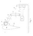
- FIGS. 1 and 2show a front view and a plan view of a grinding apparatus 1 for machine grinding of rotor blades 100.
- an industrial robot 30is arranged longitudinally displaceable on the wall 60 of a building to the right of the rotor blade 100.
- the industrial robot 30can travel along wall rails 60 along the longitudinal axis L of the rotor blade 100 by means of a running gear 32 on the wall 60.
- the industrial robot 30is shown only symbolically and can be any industrial robot that is suitable for the task described below.
- the industrial robot 30includes a landing gear 32, a drive motor 40, a first arm 34 hinged to the landing gear 32, a second arm 36 hinged to the first arm 34, and a head 38 attached to the chassis second arm is hinged.
- more pivoting or rotating axescan be provided. All axes of the industrial robot 30 are motor-driven in the usual way and are controlled by means of an NC control by means of a program.
- Attached to the head 38 of the industrial robot 30is a grinding unit in the form of a drum grinding unit 10, which can be guided NC-controlled by the industrial robot 30 along the surface 102 of the rotor blade 100 to grind the surface. With the aid of the industrial robot 30, it is thus possible to mechanically grind at least one side of the surface 102 of the rotor blade 100.
- a second industrial robot 30may be provided with a grinding unit 10, 50, 70.
- the robot sheet 100may also be rotatably mounted about its longitudinal axis, so that the side to be ground can be rotated in the direction of the industrial robot 30.
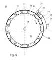
- FIG. 3shows a cross section through a preferred drum grinding unit 10.
- the drum grinding unit 10comprises a fixed suction drum 15, which is equipped with suction openings 16 at its periphery.
- the elastic clamping elements 17are arranged to the jacket of the fixed drum 15, which preferably consists of a light metal.
- the elastic clamping elements 17are preferably made of a plastic material and are supplied via a compressed air inlet 18 with tensioning air.
- the clamping elements 17are pneumatically connected to each other via channels 19 so that they form between them air-permeable spaces 11, can be sucked through the dust in the suction drum 15 inside.
- the clamping elements 17are preferably designed as flat toroidal rings or as individual, arbitrarily shaped cushion.
- the abrasive sleeve 12preferably consists of a broad, abrasive grain coated abrasive belt 66 of a fabric glued together to form a cylindrical sleeve.
- the drum grinding unit 10is preferably equipped with a dust extraction 14, which makes it possible to suck the resulting grinding dust through the grinding sleeve 12 during grinding.
- the grinding sleeve 12is preferably provided over its entire surface with perforations 62, at least through the Abrasive belt layer 66 extend so that sanding dust from the grinding surface 64 through the perforation 62, the air-permeable spaces 11 between the clamping elements 17 and through the suction openings 16 can be sucked into the suction drum 15 inside. From the tensioning drum 15, the suction air is sucked together with the grinding chips through a suction air connection 14 into an exhaust system (similar to a vacuum cleaner).
- a particularly effective dust extractionis achieved when the grinding sleeve 12 additionally on the inside an air and particle stream permeable layer 13, in particular a nonwoven layer can flow through the suction air and sanding dust transverse to the grinding surface 64 from the perforation openings 62 to the air-permeable spaces 11 , This is indicated by the arrow 68 in FIG Fig. 4 indicated by way of example.
- the size and arrangement of the perforation openings 62 of the grinding sleeve 12can be selected according to the resulting grinding dust and does not need to be adapted to the arrangement of the air-permeable spaces 11 between the clamping elements 17.
- the perforation openings 62have a diameter of about 1 mm - 6 mm and are spaced from each other about 10 mm - 50 mm and distributed substantially uniformly over the entire surface of the grinding sleeve 12. Accordingly, an almost complete extraction of the grinding dust can take place, so that clogging of the grinding surface 64 of the grinding sleeve 12 is prevented for this reason and only very little dust is released into the environment.
- the drum grinding unit 10further includes a drive motor (not shown) which rotatably drives the suction drum 15 with the grinding sleeve 12 about its axis of rotation so as to grind the surface 102.
- a drive motor(not shown) which rotatably drives the suction drum 15 with the grinding sleeve 12 about its axis of rotation so as to grind the surface 102.
- the industrial robot 30preferably comprises in its head 38 or in its arms 34, 36 a pressure sensor (not shown) in order to regulate the contact pressure of the grinding unit 10 on the rotor blade 100.
- the drum grinding unit 10is further equipped with a cleaning device 20.
- the cleaning device 20comprises a brush 22 for brushing the grinding surface 64 of the grinding sleeve 12.
- the cleaning device 20has a nozzle 24, with the compressed air can be inflated onto the surface 64 of the grinding sleeve 12.
- the cleaning device 20has a surrounding hood 28, to which a suction 26 is connected in order to suck off the grinding dust dissolved by the brush 22 and the nozzle 24.
- the suction 26can be connected to the suction of the suction drum 15.
- the cleaning device 20effectively loosens abrasive dust adhered to the grinding surface 64 of the grinding sleeve 12 which can not be removed by normal suction. This is particularly important for an effective use of a grinding device 1 according to the invention, since an industrial robot 30 can only be usefully used for grinding rotor blades 100 if the service life of the grinding means 12, 52 is so high that a significant area of the rotor blade 100 is ground can be without the abrasive 12, 52 must be replaced. With the aid of the cleaning device 20 it is possible to remove even firmly adhering or sticky grinding dust of the viscoelastic coatings of a rotor blade 100 from the grinding surface 64 of an abrasive sleeve 12 or the abrasive belt 52 described later.
- FIGS. 6 and 7show a further embodiment of a grinding device 1 with an industrial robot 30.
- the industrial robotis guided longitudinally displaceable by means of a running gear 32 on floor rails 44 on the floor 61 of a system.
- FIG. 7shows an alternative embodiment, in which the industrial robot 30 is guided via a chassis 32 on wall rails 42 on the wall 60 of a building.
- the grinding device 1 of Figures 5 and 6differs from the embodiment according to FIG. 1 and 2 in that at the head 38 of the industrial robot 30, a quad grinding unit 70 is mounted, which three Trommelschleifechen 10, such as those of Figures 3 - 5 and a dust removal unit in the form of a cleaning roller 72.
- the quad grinding unit 70similar to a tool turret, can be pivoted through an angle of 90 °, so that either a new Drum grinding unit 10 or the cleaning roller 72 can be used on the rotor blade 100.
- the cleaning roller 72is constructed similar to the drum grinding unit 10, but instead of a grinding sleeve 12 has a cleaning sleeve of a soft dust-absorbing and air-permeable fabric or nonwoven material. With the aid of the dust removal unit in the form of a cleaning roller 72, the surface 102 of the rotor blade 100 can be mechanically cleaned of the remaining dust after the grinding process, so that it can be recoated immediately thereafter.
- the grinding devices 10 and the cleaning roller 72are not each equipped with their own cleaning device 20, but a common cleaning device 20 is provided for all four units 10, 72.
- the cleaning device 20is fixed to the head 38 at a fixed position, for example in the position of FIG. 6 .
- the drum grinding devices 10 and the cleaning roller 72are respectively pivoted to the cleaning device 20 and cleaned there.
- a cleaning of one of the drum grinding units 10 and the cleaning roller 72is possible while at the same time another unit 10, 72 is in engagement with the rotor blade 100.
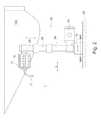
- FIG. 8shows a further embodiment of the grinding apparatus 1 for machine grinding of rotor blades 100 for wind turbines.
- the industrial robot 30feeds a belt grinding unit 50 along the surface 102 of the rotor blade in order to grind it.
- the belt grinding unit 50comprises a frame 51, on which guide rollers 54 are rotatably mounted, which guide a grinding belt 52 endlessly.
- a tension roller 56biases the abrasive belt 52.
- One of the guide rollers 54is preferably driven by an electric motor to circulate the abrasive belt 52.
- the abrasive belt 52is pressed by means of pressure elements 58 evenly against the surface 102 of the rotor blade 100, so that a uniform grinding pressure is ensured.
- the pressure elements 58are further provided with a suction 59 so that sanding dust can be sucked off directly during grinding.
- the abrasive belt 52is preferably perforated as well as the grinding sleeve 12 described above on its entire surface, so that the grinding dust can be removed by the shortest route from the grinding surface 53 and a virtually dust-free grinding is possible.
- a significant advantage of the belt grinding unit 50is that only a portion of the abrasive belt 52 is in sliding engagement with the surface 102 of the rotor blade 100 during grinding. Thus, it is possible to subject the areas that are currently not in engagement with the surface 102, a cleaning by a cleaning device 20.
- the cleaning device 20comprises, as in the embodiments described above, a nozzle 24 for blowing compressed air onto the abrasive surface to remove adhered abrasive dust.
- the cleaning device 20comprises a brush 22 to remove more adherent abrasive dust from the abrasive surface of the abrasive belt 52. The dissolved grinding dust is sucked through a suction 26.
- the cleaning device 20is surrounded by a hood 28 so that no dust is released to the environment.
- the cleaning device 20it is possible to continuously clean the abrasive belt 52 during operation on its abrasive surface, so that grinding dust can not adhere and there is no clogging of the abrasive belt 52.
- Another advantage of the belt grinding unit 50 also compared to drum grinding unitsis that their grinding performance is adaptable by a corresponding dimensioning of the abrasive surface.
- the abrasive surfacewhich is determined by the width and length of the abrasive belt 52, the grinding performance can be adjusted to the respective rotor blade to be ground that no or at most a few changes of the abrasive belt 52 per grinding pass are necessary.
- the industrial robot 30may be mounted on the wall 60 as well as on the floor by means of a drive unit 32, 32 ' 61 and overall along the longitudinal direction L on the rotor blade 100 drive along. In Fig. 9 both alternatives of the drive unit 32 and 32 'are shown. Furthermore, the industrial robot 30 may be equipped on one of its arms 34, 36 or on its head 38 with pressure sensors to precisely adjust the contact pressure of the belt grinding unit 50 to the surface 102.
- these industrial robots 30can also assume other functions, such as dust removal of the rotor blade 100 and painting or coating of the rotor blade 100.
- the belt grinding unit 50may be equipped with a dust belt made of an air-permeable cloth or nonwoven material. This is similar to the abrasive belt 52 guided along the surface 102 of the rotor blade 100 and there mechanically picks up the adhering sanding dust and cleans the surface 102 so that it can then be immediately painted or coated.
- the industrial robot 30 used for grinding or dedustingcan also be used.
- the complete coating processconsisting of several painting, grinding and cleaning operations can be carried out.
- Manual activitiessuch as manual grinding or manual cleaning are therefore completely eliminated. This shortens the production time for the rotor blade of wind turbines and, correspondingly, the production costs.
- a high reduction of abrasivesis achieved by cleaning the abrasive, which in turn lowers the manufacturing cost.
Landscapes
- Engineering & Computer Science (AREA)
- Mechanical Engineering (AREA)
- Robotics (AREA)
- Finish Polishing, Edge Sharpening, And Grinding By Specific Grinding Devices (AREA)
Abstract
Description
Translated fromGermanDie vorliegende Erfindung betrifft eine Schleifvorrichtung zum maschinellen Schleifen von Rotorblättern für Windkraftanlagen. Mit Hilfe der Schleifvorrichtung können Schleifarbeiten bei der Herstellung und bei der Wartung von Rotorblättern automatisiert werden.The present invention relates to a grinding apparatus for machine grinding rotor blades for wind turbines. The grinding device can be used to automate grinding operations during the manufacture and maintenance of rotor blades.
Als eine der umweltfreundlichsten Formen der Energiegewinnung wird die Verwendung von Windkraft zur Stromerzeugung angesehen. Hierzu werden Windkraftanlagen verwendet, welche einen Rotor aufweisen, der einen Generator antreibt und der an einem Mast drehbar gelagert ist. Die Belastungen, denen die Bauteile, insbesondere die Rotorblätter der Windkraftanlage ausgesetzt sind, sind jedoch enorm.As one of the most environmentally friendly forms of energy production, the use of wind power for power generation is considered. For this purpose, wind turbines are used which have a rotor which drives a generator and which is rotatably mounted on a mast. However, the stresses to which the components, in particular the rotor blades of the wind turbine are exposed, are enormous.
Witterungseinflüsse, wie zum Beispiel Wind, Wasser, Hagel, UV-Strahlung, Erosions- und Biegebelastungen stellen höchste Anforderungen an das Material der Rotorblätter. Die Funktionsfähigkeit und die Oberflächenqualität sind wesentlich für die Effektivität und Wirtschaftlichkeit von Windkraftanlagen. Daher weisen die Rotorblätter eine besondere Beschichtung auf, deren Aufbringung sehr zeitaufwendig ist, da jede einzelne Schicht der Beschichtung in der Regel beschliffen werden muss.Weather influences, such as wind, water, hail, UV radiation, erosion and bending loads place the highest demands on the material of the rotor blades. The functionality and surface quality are essential for the effectiveness and efficiency of wind turbines. Therefore, the rotor blades have a special coating, the application of which is very time-consuming, since each individual layer of the coating usually has to be ground.
Die extrem belasteten Kunststoffoberflächen von Rotorblättern sind mehrfach beschichtet. Die Beschichtungssysteme zum Schutz der Oberflächen bestehen aus einem sogenannten Gelcoat, Spachtel, Kantenschutz und Decklacken. Die dafür eingesetzten Produkte bestehen in der Regel aus lösemittelfreien, zweikomponentigen Polyurethanverbindungen. Nach dem Auftrag der einzelnen Schichten müssen diese jeweils beschliffen werden.The extremely contaminated plastic surfaces of rotor blades are coated several times. The coating systems for protecting the surfaces consist of a so-called gelcoat, spatula, edge protection and topcoats. The products used for this purpose generally consist of solvent-free, two-component polyurethane compounds. After the application of the individual layers, these must be ground in each case.
Diese Schleifarbeiten sind ein sehr personalintensiver Prozess, da sie manuell mit Handschleifmaschinen durchgeführt werden. Die zu schleifenden Rotorblätter weisen beispielsweise eine Länge von bis zu ca. 80 m und eine zu beschleifende Fläche von bis zu ca. 300 qm auf. Dementsprechend ist die manuell zu beschleifende Fläche sehr groß.These sanding operations are a very labor intensive process as they are done manually with hand grinders. The rotor blades to be ground For example, have a length of up to about 80 m and a surface to be ground of up to about 300 square meters. Accordingly, the area to be ground manually is very large.
Ein weiterer Grund dafür, dass Schleifarbeiten an Rotorblättern immer noch manuell mithilfe von Handschleifmaschinen, beispielsweise mit Exzenterschleifern mit Staubabsaugung durchgeführt werden, besteht darin, dass die zu beschleifenden Rotorblätterbeschichtungen sehr zähelastisch eingestellt sind und sich daher die Schleifscheiben sehr schnell zusetzen. Mit einer Schleifscheibe kann nur eine kleine Fläche beschliffen werden und dann muss diese Schleifscheibe gegen eine neue Schleifscheibe gewechselt werden, was bei Handschleifmaschinen von Hand sehr schnell möglich ist. Aufgrund der häufigen Wechselraten konnten bislang auch Schleifroboter nicht wirtschaftlich eingesetzt werden. Mit einer Schleifscheibe können trotz Absaugung in der Regel nur ca. 0,5 qm - 1,5 qm der zähelastischen Beschichtung eines Rotorblatts beschliffen werden. Die Fläche eines Windkraftflügels von ca. 60 m bis ca. 80 m Flügellänge beträgt jedoch 160 qm bis 300 qm, so dass pro Rotorblatt und Schleifdurchgang ca. 300 - 600 Schleifscheiben eingesetzt werden müssen. In der Regel gibt es 3 - 4 Schleifdurchgänge pro Rotorblatt.Another reason that grinding work on rotor blades is still done manually using hand grinders, for example, with eccentric grinders with dust extraction, is that the rotor blade coatings to be ground are very tough elastic and therefore set the grinding wheels very quickly. With a grinding wheel, only a small area can be ground and then this grinding wheel has to be replaced with a new grinding wheel, which is possible very quickly with hand grinding machines by hand. Due to the frequent change rates, grinding robots could not be used economically. With a grinding wheel, only approx. 0.5 m² - 1.5 m² of the viscoelastic coating of a rotor blade can be sanded despite extraction. However, the area of a wind turbine blade of approx. 60 m to approx. 80 m wing length is 160 m² to 300 m², so that approx. 300 - 600 grinding wheels have to be used per rotor blade and grinding cycle. There are usually 3-4 sanding passes per rotor blade.
Die zähelastischen Beschichtungen der Rotorblätter werden deshalb verwendet, weil Rotorblätter sich mit Geschwindigkeiten von bis zu 300 km/h bewegen und sie nicht beschädigt werden dürfen, wenn beispielsweise Hagelkörner auf sie aufschlagen. In den Druckschriften
Die gewaltigen Dimensionen der Rotorblätter und die Probleme, die beim Beschleifen der zähelastischen Beschichtung auftreten, haben bisher noch keine Automatisierung der Schleifarbeiten zugelassen. Die Kosten der Schleifarbeiten können 30% und mehr der Herstellungskosten eines Rotorblatts betragen.The enormous dimensions of the rotor blades and the problems that occur when grinding the viscoelastic coating, have not yet allowed automation of the grinding work. The cost of the grinding work can be 30% and more of the manufacturing cost of a rotor blade.
Es ist daher die Aufgabe der vorliegenden Erfindung, die oben genannten Probleme zu lösen und den Schleifprozess bei Rotorblättern für Windkraftanlagen zu verbessern und kostengünstiger zu gestalten.It is therefore the object of the present invention to solve the above-mentioned problems and to improve the grinding process in rotor blades for wind turbines and to make them cheaper.
Die oben genannte Aufgabe wird gelöst durch eine Schleifvorrichtung zum maschinellen Schleifen von Rotorblättern für Windkraftanlagen gemäß Patentanspruch 1.The above-mentioned object is achieved by a grinding device for the mechanical grinding of rotor blades for wind power plants according to
Insbesondere werden die oben genannten Aufgaben gelöst durch eine Schleifvorrichtung zum maschinellen Schleifen von Rotorblättern für Windkraftanlagen, aufweisend mindestens einen Industrieroboter und eine Schleifeinheit, die vom Industrieroboter geführt wird, wobei die Schleifeinheit ein Schleifmittel und eine Reinigungsvorrichtung aufweist, die das Schleifmittel an dessen Schleifoberfläche reinigt.In particular, the above objects are achieved by a grinding apparatus for machine grinding rotor blades for wind turbines, comprising at least one industrial robot and a grinding unit, which is guided by the industrial robot, wherein the grinding unit comprises an abrasive and a cleaning device which cleans the abrasive on the grinding surface.
Dadurch, dass eine Schleifeinheit verwendet wird, die ein Schleifmittel umfasst, welches an der Schleifoberfläche gereinigt wird, kann vorteilhafterweise in der Schleifvorrichtung ein Industrieroboter verwendet werden, der eine Schleifeinheit führt. Dies war bei konventionellen Schleifmitteln nicht möglich, da aufgrund des schnellen Zusetzens der Schleifmittel und der hohen Wechselraten der Schleifmittel ein Robotereinsatz unwirtschaftlich war. Durch die Reinigungsvorrichtung erhöht sich nun die Standzeit des Schleifmittels um das 10 bis 100-fache, sodass zum Schleifen der Oberfläche eines Rotorblatts kein oder nur sehr wenige Werkzeugwechsel erforderlich sind und ein Industrieroboter zum Schleifen von Rotorblättern nun wirtschaftlich verwendet werden kann.By using a grinding unit comprising an abrasive which is cleaned on the grinding surface, an industrial robot carrying a grinding unit can be advantageously used in the grinding device. This was not possible with conventional abrasives because robotic use was uneconomical due to the rapid addition of the abrasives and the high change rates of the abrasives. The cleaning device now increases the service life of the abrasive by 10 to 100 times, so that no or very few tool changes are required for grinding the surface of a rotor blade and an industrial robot for grinding rotor blades can now be used economically.
Bevorzugt reinigt die Reinigungsvorrichtung die Schleifoberfläche des Schleifmittels entweder von Zeit zu Zeit oder während des Schleifens kontinuierlich. Die Schleifoberfläche kann, wenn notwendig, von Zeit zu Zeit gereinigt werden, etwa abhängig vom Grand der Zusetzung der Schleifoberfläche, in dem die Schleifoberfläche nach einer gewissen Schleifzeit mit einer Reinigungsvorrichtung in Kontakt gebracht. Alternativ ist die Reinigungsvorrichtung während des Schleifens mit einem Teil der Schleifoberfläche in Kontakt und reinigt diese kontinuierlich während des Schleifens.Preferably, the cleaning device continuously cleans the abrasive surface of the abrasive either from time to time or during sanding. The abrasive surface may be cleaned from time to time, as necessary, depending on the size of the abrasive surface added, in which the abrasive surface is contacted with a cleaning device after a period of grinding. Alternatively, during grinding, the cleaning device contacts and cleans part of the abrasive surface continuously during grinding.
Bevorzugt reinigt die Reinigungsvorrichtung die Schleifoberfläche mittels einer Düse zum Aufblasen von Druckluft und/oder einer Vorrichtung zum Absaugen von Schleifstaub und/oder einer Bürste zum Abbürsten der Schleifoberfläche. Diese drei Maßnahmen, entweder einzeln oder in beliebiger Kombination miteinander führen dazu, dass auch der Abrieb von zähelastischen Beschichtungen von Schleifoberfläche des Schleifmittels quasi vollständig entfernt wird und dort nicht anhaften und die Schleifoberfläche zusetzen kann. Durch das aktive Abreinigen der Schleifoberfläche erhöht sich die Standzeit des Schleifmittels jedoch auch die Qualität des Schleifvorgangs.Preferably, the cleaning device cleans the abrasive surface by means of a nozzle for inflating compressed air and / or a device for extracting abrasive dust and / or a brush for brushing the abrasive surface. These three measures, either individually or in any desired combination with one another, mean that even the abrasion of viscous coatings from the grinding surface of the abrasive agent is virtually completely removed and can not adhere there and can clog the grinding surface. By actively cleaning the abrasive surface, the life of the abrasive increases but also the quality of the grinding process.
Beim Aufblassen von Druckluft mittels einer Düse werden anhaftende Schleifpartikel gelöst, durch das Absaugen von Schleifstaub werden diese aktiv von der Schleifoberfläche entfernt und mit einer Bürste ist es möglich, selbst stark an der Schleifoberfläche anhaftenden Schleifstaub oder größere klebrige Anhaftungen sicher zu entfernen. Eine derartige Schleifvorrichtung kann sowohl für eine diskontinuierliche wie für eine kontinuierliche Reinigung der Schleifoberfläche des Schleifmittels verwendet werden.When compressed air is compressed by means of a nozzle, adhering abrasive particles are loosened, the abrasive dust is actively removed from the grinding surface and a brush makes it possible to safely remove even abrasive dust or larger sticky deposits adhering to the grinding surface. Such a grinding device can be used for both discontinuous and continuous cleaning of the abrasive surface of the abrasive.
In einer bevorzugten Ausführungsform weist die Schleifvorrichtung weiterhin eine Antriebseinheit zum Verfahren des Industrieroboters in Richtung der Längsachse L eines Rotorblatts auf. Damit kann der Industrieroboter an dem Rotorblatt entlang fahren und die gesamte Oberfläche des Rotorblattes beschleifen.In a preferred embodiment, the grinding device further comprises a drive unit for moving the industrial robot in the direction of the longitudinal axis L of a rotor blade. Thus, the industrial robot can drive along the rotor blade and grind the entire surface of the rotor blade.
In einer bevorzugten Ausführungsform weist die Schleifeinheit eine Trommelschleifeinheit mit einer Schleifhülse auf. Eine Schleifhülse hat eine vergleichsweise große Schleifoberfläche, welche an ihrem nicht mit dem Rotorblatt aktuell in Eingriff stehenden Bereich gereinigt werden kann. Die Trommelschleifeinheiten sind außerdem sehr kompakt und lassen sich gut mit einem Industrieroboter bewegen, um die Oberfläche des Rotorblatts wie gewünscht zu beschleifen.In a preferred embodiment, the grinding unit comprises a drum grinding unit with a grinding sleeve. An abrasive sleeve has a comparatively large abrasive surface that can be cleaned at its area not currently engaged with the rotor blade. The drum grinding units are also very compact and can be easily moved with an industrial robot to grind the surface of the rotor blade as desired.
In einer bevorzugten Ausführungsform weist die Trommelschleifeinheit eine feste Saugtrommel und elastische, pneumatisch ausdehnbare Spannelemente auf, die am Mantel der Saugtrommel angeordnet sind, wobei die Schleifhülse durch Druckbeaufschlagung auf die Spannelemente an der Saugtrommel befestigt wird. Durch eine solche Ausgestaltung der Trommelschleifeinheit ist es möglich, die Schleifhülse sehr einfach und schnell an einer Saugtrommel zu befestigen, sodass ein Werkzeugwechsel, d.h. ein Wechsel der Schleifhülse sehr leicht und schnell vorgenommen werden kann.In a preferred embodiment, the drum grinding unit comprises a fixed suction drum and elastic, pneumatically expandable clamping elements which are arranged on the jacket of the suction drum, wherein the grinding sleeve is fixed by pressurizing the clamping elements on the suction drum. Such a design of the drum grinding unit, it is possible to attach the grinding sleeve very easy and fast to a suction drum, so that a tool change, ie a change of the grinding sleeve can be made very easily and quickly.
Die elastischen, pneumatisch ausdehnbaren Spaltelemente haben weiterhin den Vorteil, dass die Schleifhülse sich in gewissem Maße an die Oberfläche des Rotorblatts anpasst und kleinere Ungenauigkeiten bei der Positionierung der Schleifvorrichtung ausgleicht.The elastic, pneumatically expandable splitting elements also have the advantage that the grinding sleeve adapts to a certain extent to the surface of the rotor blade and compensates for minor inaccuracies in the positioning of the grinding device.
Bevorzugt weist die Saugtrommel Absaugöffnungen am Mantel auf, zwischen den Spannelementen sind luftdurchlässige Räume vorhanden und die Schleifhülse ist im Wesentlichen über ihre gesamte Oberfläche mit Perforationsöffnungen versehen, damit Schleifstaub von der Schleifoberfläche durch die Perforationsöffnungen, die luftdurchlässigen Räumen und durch die Absaugöffnungen hindurch abgesaugt werden kann. Mit einem derartigen Aufbau der Trommelschleifeinheit ist es möglich, einerseits die oben genannte einfach pneumatische Spannung der Schleifhülse an einer festen Saugtrommel vorzunehmen und andererseits durch die Spannelemente, die Saugtrommel und durch die Schleifhülse hindurch Schleifstaub von der Schleifoberfläche abzusaugen. Damit kann ein vollflächiger Staubabtrag von der Schleifoberfläche erfolgen, wodurch ein Zusetzen der Schleifoberfläche weiterhin minimiert wird und ein nahezu staubloses Schleifen ermöglicht wird.The suction drum preferably has suction openings on the casing, air-permeable spaces are present between the clamping elements and the grinding sleeve is provided with perforation openings substantially over its entire surface so that grinding dust can be sucked from the grinding surface through the perforation openings, the air-permeable spaces and through the suction openings , With such a structure of the drum grinding unit, it is possible to make the above-mentioned single pneumatic tension of the grinding sleeve on a fixed suction drum and on the other hand to suck off grinding dust from the grinding surface through the clamping elements, the suction drum and the grinding sleeve. This allows a complete dust removal from the grinding surface, whereby a clogging of the grinding surface is further minimized and a virtually dustless grinding is possible.
In einer bevorzugten Ausführungsform weist die Schleifhülse eine luft- und partikelstromdurchlässige Schicht, insbesondere eine Fließschicht auf, durch die hindurch Absaugluft und Schleifstaub quer hinter der Schleifoberfläche von den Perforationsöffnungen zu den luftdurchlässigen Räumen strömen kann. Durch die Fließschicht, durch die Absaugluft und Schleifstaub quer hinter der Oberfläche strömen kann, können die Perforationsöffnungen vollflächig über die Schleifoberfläche der Schleifhülse angeordnet sein, sodass der Weg des Schleifstaubes von seiner Entstehung an der Schleifoberfläche bis zur Perforationsöffnung, an der abgesaugt wird, sehr kurz ist. Dementsprechend ermöglicht die luft- und partikelstromdurchlässige Schicht hinter der Schleifoberfläche eine vollflächige Staubabsaugung und verhindert ein Zusetzen der Schleifhülse. Dieser Staubtransport erfolgt somit vollflächig und unabhängig von der Anordnung der luftdurchlässigen Räume, die von den elastischen pneumatisch ausdehnbaren Elementen gebildet werden.In a preferred embodiment, the grinding sleeve has an air and particle stream permeable layer, in particular a flow layer, through which suction air and grinding dust can flow transversely behind the grinding surface from the perforation openings to the air-permeable spaces. Through the flow layer, through which the suction air and grinding dust can flow transversely behind the surface, the perforation openings can be arranged over the entire surface of the grinding surface of the grinding sleeve, so that the path of the grinding dust from its formation on the grinding surface up to Perforation opening, is sucked on, is very short. Accordingly, the air and particle stream permeable layer behind the grinding surface allows a full-surface dust extraction and prevents clogging of the grinding sleeve. This dust transport thus takes place over the entire surface and independently of the arrangement of the air-permeable spaces, which are formed by the elastic pneumatically expandable elements.
Bevorzugt umfasst die Schleifeinheit mehrere Trommelschleifeinheiten, die jeweils in Kontakt mit der Oberfläche des Rotorblatts gebracht werden können. Durch eine solche Anordnung, beispielsweise in Form eines Trommelschleifeinheiten-Revolvers können Schleifhülsen, die im Moment nicht im Eingriff mit dem Rotorblatt stehen gewechselt oder gereinigt werden, ohne dass sich dadurch die Schleifzeit für das Rotorblatt insgesamt signifikant verlängert. Auch ist es möglich auf den einzelnen Trommelschleifeinheiten Schleifhülsen unterschiedlicher Körnung oder Staubwalzen aufzubringen und sehr schnell einzusetzen.Preferably, the grinding unit comprises a plurality of drum grinding units, each of which can be brought into contact with the surface of the rotor blade. By such an arrangement, for example in the form of a drum grinding unit turret grinding sleeves that are currently not engaged with the rotor blade can be changed or cleaned without this significantly extends the grinding time for the rotor blade as a whole. It is also possible to apply abrasive sleeves of different grain size or dust rollers to the individual drum grinding units and to use them very quickly.
Bevorzugt reinigt eine Reinigungseinheit eine der Trommelschleifeinheiten, die nicht in Eingriff mit der Oberfläche des Rotorblatts stehen.Preferably, a cleaning unit cleans one of the drum grinding units that are not engaged with the surface of the rotor blade.
In einer weiteren bevorzugten Ausführungsform weist die Schleifeinheit eine Bandschleifeinheit mit einem umlaufenden Schleifband auf. Ein umlaufendes Schleifband ist nur mit einem Teil seiner Schleifoberfläche in Eingriff mit dem Rotorblatt und der nicht in Eingriff mit dem Rotorblatt stehende Teil des umlaufenden Schleifbandes kann an einer Reinigungsvorrichtung vorbeifahren, die eine Reinigung der Schleifoberfläche vornimmt. Dementsprechend eignet sich diese Ausführungsform ebenfalls besonders gut für eine kontinuierliche Reinigung der Schleifoberfläche während des Betriebs.In a further preferred embodiment, the grinding unit has a belt grinding unit with a revolving grinding belt. A rotating abrasive belt is in engagement with the rotor blade with only a portion of its abrasive surface, and the portion of the rotating abrasive belt that is out of engagement with the rotor blade may pass a cleaning device that cleans the abrasive surface. Accordingly, this embodiment is also particularly well suited for continuous cleaning of the abrasive surface during operation.
Bevorzugt ist als Schleifband ein perforiertes Schleifband, welches im Wesentlichen über seine gesamte Oberfläche mit Perforationsöffnungen versehen ist. Durch die Perforationsöffnungen kann der entstehende Schleifstaub auf kürzestem Wege hinter die Schleifebene abgesaugt werden, sodass ein Zusetzen des Schleifbandes vermieden wird und ein nahezu staubloses Schleifen ermöglicht wird.Preferably, the sanding belt is a perforated sanding belt which is provided with perforation openings substantially over its entire surface. Through the perforation openings, the resulting sanding dust can be sucked by the shortest route behind the sanding plane, so that clogging The sanding belt is avoided and a virtually dustless grinding is possible.
In einer weiteren bevorzugten Ausführungsform weist die Schleifvorrichtung weiterhin eine Staubentfernungseinheit mit einem umlaufenden Staubband oder einer Staubhülse auf, welche durch den Industrieroboter an zumindest einer Oberfläche eines Rotorblatts entlang geführt werden, um die Oberfläche des Rotorblatts mechanisch von Staub zu befreien. Mit der erfindungsgemäßen Vorrichtung kann nicht nur die Oberfläche eines Rotorblatts automatisiert geschliffen werden, sondern es ist auch möglich, nach dem Schleifen mit einem umlaufenden Staubband oder einer Staubhülse mechanisch Staub von der geschliffenen Oberfläche restlos zu entfernen, sodass unmittelbar danach einer Auftrag einer weiteren Lackschicht erfolgen kann. Vorteilhafterweise kann hierzu die schon vorhandene Schleifeinheit als Staubentfernungseinheit verwendet werden, sodass hier nur ein geringer zusätzlicher Aufwand betrieben werden muss. Ein automatisiertes Entstauben der Schleifoberfläche ist wesentlich schneller durchführbar als manuelles Entstauben mittels Tüchern oder Ähnlichem.In a further preferred embodiment, the grinding device further comprises a dust removal unit with a circumferential dust belt or a dust sleeve, which are guided by the industrial robot along at least one surface of a rotor blade, to mechanically remove dust from the surface of the rotor blade. With the device according to the invention not only the surface of a rotor blade can be ground automatically, but it is also possible to mechanically remove dust from the ground surface after grinding with a rotating dust belt or a dust sleeve, so immediately followed by an order of another paint layer can. Advantageously, the already existing grinding unit can be used as a dust removal unit, so that only a small additional effort has to be operated here. An automated dedusting of the grinding surface is much faster feasible than manual dust removal by means of cloths or the like.
In einer bevorzugten Ausführungsform weist der Industrieroboter Drucksensoren an zumindest einem Roboterarm oder am Kopf zur Steuerung des Anpressdrucks der Schleifeinheit auf das Rotorblatt auf. Mit Hilfe dieser Drucksensoren wird sichergestellt, dass der Roboterarm den notwendigen Schleifdruck bzw. den notwendigen und genau definierten Druck zur Abreinigung der Oberfläche des Rotorblatts ausübt. Dadurch wird ein sehr gleichmäßiges Schleif- und Reinigungsergebnis erzielt.In a preferred embodiment, the industrial robot has pressure sensors on at least one robot arm or on the head for controlling the contact pressure of the grinding unit on the rotor blade. With the help of these pressure sensors, it is ensured that the robot arm exerts the necessary grinding pressure or the necessary and precisely defined pressure for cleaning the surface of the rotor blade. This achieves a very uniform grinding and cleaning result.
Bevorzugt wird der Industrieroboter auch zum Lackieren des Rotorblattes eingesetzt. Damit verringern sich die Investitionskosten der gesamten Anlage auf ein Minimum, wobei in einer Anlage sowohl das Lackieren eines Rotorblattes als auch das Schleifen bzw. das Entstauben eines Rotorblatts mit demselben Industrieroboter erfolgt, der die dazu erforderlichen Werkzeuge zwischen den einzelnen Arbeitsgängen lediglich wechseln muss. Auch ein derartiger Wechsel kann selbstverständlich automatisch erfolgen. Dementsprechend verkürzen sich die gesamten Beschichtungsvorgänge, inklusive Schleifen und Entstauben eines Rotorblattes auf ein Bruchteil der Zeit, verglichen mit konventionellen System in denen manuell geschliffen werden muss und oft auch manuell lackiert wird. Dementsprechend verringern sich durch die erfindungsgemäße Schleifvorrichtung sowohl die Bearbeitungszeiten als auch die Bearbeitungskosten.Preferably, the industrial robot is also used for painting the rotor blade. This reduces the investment costs of the entire system to a minimum, in one system both the painting of a rotor blade and the grinding or dusting of a rotor blade with the same industrial robot takes place, which only has to change the tools required for this between the individual operations. Also, such a change can of course be done automatically. Accordingly, shorten the entire coating process, including grinding and dedusting of a rotor blade in a fraction of the time compared to conventional system in which must be ground manually and often also painted manually. Accordingly, both the processing times and the processing costs are reduced by the grinding device according to the invention.
Weitere bevorzugte Ausführungsformen der Erfindung ergeben sich aus den Unteransprüchen.Further preferred embodiments of the invention will become apparent from the dependent claims.
Im Folgenden werden bevorzugte Ausführungsformen der Erfindung mit Bezug auf die begleitenden Zeichnungen beschrieben. In diesen zeigt:
- Fig.1:
- Eine erste bevorzugte Ausführungsform einer Schleifvorrichtung zum maschinellen Schleifen von Rotorblättern für Windkraftanlagen in einer Vorderansicht;
- Fig. 2:
- die Schleifvorrichtung der
Fig. 1 in einer Draufsicht; - Fig. 3:
- eine Trommelschleifeinheit der Schleifvorrichtung gemäß
Fig. 1 in einer Schnittansicht von der Seite; - Fig. 4:
- ein Detail der Trommelschleifeinheit der
Fig. 3 in einer Schnittansicht von der Seite; - Fig. 5:
- die Trommelschleifeinheit der
Fig. 3 in einer Schnittansicht von vorne; - Fig. 6:
- eine zweite Ausführungsform einer Schleifvorrichtung zum maschinellen Schleifen von Rotorblättern für Windkraftanlagen in einer Vorderansicht;
- Fig. 7:
- die Schleifvorrichtung gemäß
Fig. 6 mit einer alternativen Führung des Industrieroboters an der Wand in einer Draufsicht; und - Fig. 8:
- eine Vorderansicht einer weiteren bevorzugten Ausführungsform einer Schleifvorrichtung zum maschinellen Schleifen von Rotorblättern für Windkraftanlagen mit einer Bandschleifeinheit in einer Vorderansicht.
- Fig.1:
- A first preferred embodiment of a grinding apparatus for machine grinding rotor blades for wind turbines in a front view;
- Fig. 2:
- the grinding device of
Fig. 1 in a plan view; - 3:
- a drum grinding unit of the grinding apparatus according to
Fig. 1 in a sectional view from the side; - 4:
- a detail of the drum grinding unit of
Fig. 3 in a sectional view from the side; - Fig. 5:
- the drum grinding unit of
Fig. 3 in a sectional view from the front; - Fig. 6:
- a second embodiment of a grinding apparatus for machine grinding rotor blades for wind turbines in a front view;
- Fig. 7:
- the grinding device according to
Fig. 6 with an alternative guide of the industrial robot on the wall in a plan view; and - Fig. 8:
- a front view of another preferred embodiment of a grinding apparatus for machine grinding rotor blades for wind turbines with a belt grinding unit in a front view.
Im Folgenden werden bevorzugte Ausführungsformen der Erfindung mit Bezug auf die Figuren beschrieben. Einzelne Merkmale der hier beschriebenen Ausführungsformen können mit anderen Ausführungsformen der Erfindung kombiniert werden.Hereinafter, preferred embodiments of the invention will be described with reference to the figures. Individual features of the embodiments described herein may be combined with other embodiments of the invention.
Die
An dem Kopf 38 des Industrieroboters 30 ist eine Schleifeinheit in Form einer Trommelschleifeinheit 10 befestigt, die NC-gesteuert durch den Industrieroboter 30 entlang der Oberfläche 102 des Rotorblatts 100 entlang geführt werden kann, um die Oberfläche zu beschleifen. Mit Hilfe des Industrieroboters 30 ist es damit möglich, zumindest eine Seite der Oberfläche 102 des Rotorblatts 100 maschinell zu beschleifen. Für die andere Seite des Rotorblatts 100 kann ein zweiter Industrieroboter 30 mit einer Schleifeinheit 10, 50, 70 vorgesehen sein. Alternativ kann das Roboterblatt 100 auch um seine Längsachse drehbar gelagert sein, so dass die zu beschleifende Seite in Richtung des Industrieroboters 30 gedreht werden kann.Attached to the
Die Trommelschleifeinheit 10 ist im Folgenden in den
Ein Schleifmittel in Form einer Schleifhülse 12 wird auf die Saugtrommel 15 mit den am Mantel befindlichen Spannelementen 17 aufgeschoben und durch eine Druckbeaufschlagung auf die Spannelemente 17 an der Saugtrommel 15 befestigt. Dabei dehnen sich die Spannelemente 17 durch Einleiten von Spannluft 18 aus und halten die Schleifhülse 12 von innen fest auf der Saugtrommel 15. Durch diese pneumatische Befestigungsart ist es besonders einfach, die Schleifhülse 12 auf der Saugtrommel 15 zu spannen und die Schleifhülse 12 nach Ablauf ihrer Standzeit auszutauschen. Die Schleifhülse 12 besteht bevorzugt aus einem breiten, mit Schleifkorn beschichteten Schleifband 66 aus einem Gewebe, das zu einer zylinderförmigen Hülse zusammengeklebt ist.An abrasive in the form of a grinding
Die Trommelschleifeinheit 10 ist bevorzugt mit einer Staubabsaugung 14 ausgerüstet, die es ermöglicht, den entstehenden Schleifstaub durch die Schleifhülse 12 hindurch während des Schleifens abzusaugen. Dazu ist die Schleifhülse 12 bevorzugt im Wesentlichen über ihre gesamte Oberfläche mit Perforationsöffnungen 62 versehen, die sich zumindest durch die Schleifbandschicht 66 erstrecken, damit Schleifstaub von der Schleifoberfläche 64 durch die Perforationsöffnungen 62, die luftdurchlässigen Räume 11 zwischen den Spannelementen 17 und durch die Absaugöffnungen 16 hindurch in die Saugtrommel 15 hinein abgesaugt werden kann. Von der Spanntrommel 15 wird die Saugluft zusammen mit den Schleifspänen durch einen Saugluftanschluss 14 hindurch in ein Absaugsystem (ähnlich einem Staubsauger) abgesaugt.The
Eine besonders effektive Staubabsaugung wird dann erreicht, wenn die Schleifhülse 12 zusätzlich auf der Innenseite eine luft- und partikelstromdurchlässige Schicht 13, insbesondere eine Vliesschicht aufweist, durch die Absaugluft und Schleifstaub quer hinter der Schleifoberfläche 64 von den Perforationsöffnungen 62 zu den luftdurchlässigen Räumen 11 strömen kann. Dies ist durch den Pfeil 68 in
Die Trommelschleifeinheit 10 umfasst weiterhin einen Antriebsmotor (nicht dargestellt), der die Saugtrommel 15 mit der Schleifhülse 12 um ihre Rotationsachse drehbar antreibt, um so die Oberfläche 102 zu beschleifen.The
Der Industrieroboter 30 umfasst bevorzugt in seinem Kopf 38 oder in seinen Armen 34, 36 einen Drucksensor (nicht dargestellt), um den Anpressdruck der Schleifeinheit 10 auf das Rotorblatt 100 zu regeln.The
Wie in
Die Reinigungsvorrichtung 20 löst auf effektive Weise an der Schleifoberfläche 64 der Schleifhülse 12 anhaftenden Schleifstaub, welcher sich nicht durch die normale Absaugung entfernen lässt. Dies ist insbesondere deshalb entscheidend für eine effektive Verwendung einer erfindungsgemäßen Schleifvorrichtung 1, da ein Industrieroboter 30 nur dann sinnvoll zum Schleifen von Rotorblättern 100 verwendet werden kann, wenn die Standzeit des Schleifmittels 12, 52 so hoch ist, dass eine signifikante Fläche des Rotorblatts 100 geschliffen werden kann, ohne dass das Schleifmittel 12, 52 ausgetauscht werden muss. Mithilfe der Reinigungsvorrichtung 20 ist es möglich, auch fest anhaftenden oder klebrigen Schleifstaub der zähelastischen Beschichtungen eines Rotorblatts 100 von der Schleifoberfläche 64 einer Schleifhülse 12 oder dem später beschriebenen Schleifband 52 zu entfernen.The
Die
Die Reinigungswalze 72 ist ähnlich der Trommelschleifeinheit 10 aufgebaut, besitzt jedoch anstatt einer Schleifhülse 12 eine Reinigungshülse aus einem weichen staubaufnehmenden und luftdurchlässigen Stoff- oder Vliesmaterial. Mit Hilfe der Staubentfernungseinheit in Form einer Reinigungswalze 72 kann die Oberfläche 102 des Rotorblatts 100 nach dem Schleifvorgang mechanisch vom verleibenden Staub gereinigt werden, so dass sie unmittelbar danach neu beschichtet werden kann.The cleaning
In der in den
Ein wesentlicher Vorteil der Bandschleifeinheit 50 liegt darin, dass während des Schleifens nur ein Teil des Schleifbands 52 sich im schleifenden Eingriff mit der Oberfläche 102 des Rotorblatts 100 befindet. Damit ist es möglich, die Bereiche, die aktuell nicht im Eingriff mit der Oberfläche 102 sind, einer Reinigung durch eine Reinigungsvorrichtung 20 zu unterziehen. Die Reinigungsvorrichtung 20 umfasst, wie bei den oben beschriebenen Ausführungsformen, eine Düse 24 zum Aufblasen von Druckluft auf die Schleifoberfläche, um anhaftenden Schleifstaub zu entfernen. Weiterhin umfasst die Reinigungsvorrichtung 20 eine Bürste 22, um stärker anhaftenden Schleifstaub von der Schleifoberfläche des Schleifbandes 52 zu entfernen. Der gelöste Schleifstaub wird durch eine Absaugung 26 abgesaugt. Die Reinigungsvorrichtung 20 ist mit einer Haube 28 umgeben, sodass kein Staub an die Umgebung abgegeben wird. Durch die Reinigungsvorrichtung 20 ist es möglich, das Schleifband 52 kontinuierlich während des Betriebs an seiner Schleifoberfläche zu reinigen, sodass Schleifstaub nicht anhaften kann und es zu keinem Zusetzen des Schleifbands 52 kommt. Dies erhöht wesentlich die Standzeit des Schleifbandes 52, sodass es möglich ist, das komplette Rotorblatt 100 mit nur einem Schleifband vollständig zu beschleifen.A significant advantage of the
Ein weiterer Vorteil der Bandschleifeinheit 50 auch gegenüber von Trommelschleifeinheiten liegt darin, dass ihre Schleifleistung durch eine entsprechende Dimensionierung der Schleifmittelfläche anpassbar ist. Durch eine Wahl der Schleifmittelfläche, die durch die Breite und Länge des Schleifbandes 52 bestimmt wird, kann die Schleifleistung so auf das jeweils zu schleifende Rotorblatt abgestimmt werden, dass kein oder allenfalls wenige Wechsel des Schleifbandes 52 pro Schleifdurchgang notwendig sind.Another advantage of the
Wie in den obigen Ausführungsformen, kann der Industrieroboter 30 mit Hilfe einer Antriebseinheit 32, 32' entweder an der Wand 60, als auch an dem Boden 61 geführt sein und insgesamt entlang der Längsrichtung L an dem Rotorblatt 100 entlang fahren. In Fig. 9 sind beide Alternativen der Antriebseinheit 32 und 32' dargestellt. Weiterhin kann der Industrieroboter 30 an einem seiner Arme 34, 36 oder an seinem Kopf 38 mit Drucksensoren ausgerüstet sein, um den Anpressdruck der Bandschleifeinheit 50 an die Oberfläche 102 genau einzustellen.As in the above embodiments, the
Mit den oben beschriebenen Ausführungsformen ist es zum ersten Mal möglich, Industrieroboter 30 wirtschaftlich beim Beschleifen von Rotorblättern 100 von Windkraftanlagen zu verwenden. Bevorzugt können diese Industrieroboter 30 auch weitere Funktionen übernehmen, wie beispielsweise das Entstauben des Rotorblatts 100 und das Lackieren bzw. Beschichten des Rotorblatts 100.With the above-described embodiments, it is possible for the first time to economically use
Wenn eine Bandschleifeinheit 50 verwendet wird, kann zum Entstauben des Rotorblatts 100, anstelle des Schleifbands 52 die Bandschleifeinheit 50 mit einem Staubband ausgerüstet werden, welches aus einem luftdurchlässigen Stoff- oder Vliesmaterial besteht. Dieses wird ähnlich wie das Schleifband 52 an der Oberfläche 102 des Rotorblatts 100 entlang geführt und nimmt dort mechanisch den anhaftenden Schleifstaub auf und reinigt die Oberfläche 102 sodass sie danach unmittelbar lackiert bzw. beschichtet werden kann.When a
Für diesen Lackiervorgang lässt sich der zum Schleifen bzw. zum Entstauben verwendete Industrieroboter 30 ebenfalls verwenden. Somit kann auf einer Anlage mit den selben Industrierobotern 30 der komplette Beschichtungsprozess, der aus mehreren Lackier-, Schleif und Reinigungsvorgängen besteht, durchgeführt werden. Manuelle Tätigkeiten wie beispielsweise ein manuelles Schleifen oder ein manuelles Reinigen entfallen somit vollständig. Damit verkürzt sich die Fertigungszeit für das Rotorblatt von Windkraftanlagen und entsprechend auch die Herstellungskosten. Weiterhin wird durch die Reinigung des Schleifmittels eine hohe Einsparung an Schleifmitteln erzielt, was wiederum die Herstellkosten senkt.For this painting process, the
Claims (15)
Translated fromGermandamit Schleifstaub von der Schleifoberfläche (64) durch die Perforationsöffnungen (62), die luftdurchlässigen Räume (11) und durch die Absaugöffnungen (16) hindurch abgesaugt werden kann.
so that grinding dust from the grinding surface (64) through the perforation openings (62), the air-permeable spaces (11) and through the suction openings (16) can be sucked through.
welche durch den Industrieroboter (30) an zumindest einer Oberfläche (102) eines Rotorblatts (100) entlang geführt werden, um die Oberfläche (102) des Rotorblatts (100) mechanisch von Staub zu befreien.
which are guided by the industrial robot (30) along at least one surface (102) of a rotor blade (100) in order to mechanically remove dust from the surface (102) of the rotor blade (100).
Priority Applications (4)
| Application Number | Priority Date | Filing Date | Title |
|---|---|---|---|
| EP20100193782EP2460624A1 (en) | 2010-12-06 | 2010-12-06 | Grinding device for mechanical grinding of rotor blades for wind power systems |
| US13/580,362US20120322349A1 (en) | 2010-12-06 | 2011-12-02 | Grinding device for machine based grinding of rotor blades for wind energy systems |
| PCT/EP2011/071656WO2012076418A1 (en) | 2010-12-06 | 2011-12-02 | Grinding device for mechanically grinding rotor blades for wind power plants |
| CN201180058860.5ACN103249523A (en) | 2010-12-06 | 2011-12-02 | Grinding device for mechanically grinding rotor blades for wind power plants |
Applications Claiming Priority (1)
| Application Number | Priority Date | Filing Date | Title |
|---|---|---|---|
| EP20100193782EP2460624A1 (en) | 2010-12-06 | 2010-12-06 | Grinding device for mechanical grinding of rotor blades for wind power systems |
Publications (1)
| Publication Number | Publication Date |
|---|---|
| EP2460624A1true EP2460624A1 (en) | 2012-06-06 |
Family
ID=44123179
Family Applications (1)
| Application Number | Title | Priority Date | Filing Date |
|---|---|---|---|
| EP20100193782CeasedEP2460624A1 (en) | 2010-12-06 | 2010-12-06 | Grinding device for mechanical grinding of rotor blades for wind power systems |
Country Status (4)
| Country | Link |
|---|---|
| US (1) | US20120322349A1 (en) |
| EP (1) | EP2460624A1 (en) |
| CN (1) | CN103249523A (en) |
| WO (1) | WO2012076418A1 (en) |
Cited By (12)
| Publication number | Priority date | Publication date | Assignee | Title |
|---|---|---|---|---|
| CN102729124A (en)* | 2012-07-09 | 2012-10-17 | 重庆大学 | Abrasive belt grinding device applicable to inner and outer cambered surfaces of blades of aerospace blisk |
| DE102013100754A1 (en)* | 2013-01-25 | 2014-07-31 | Hauni Maschinenbau Ag | Device and method for grinding at least one arranged on a cutterhead and circumferentially driven cutting knife |
| CN105290925A (en)* | 2014-09-17 | 2016-02-03 | 电子科技大学 | Industrial-robot-based abrasive belt grinding device for profiles of controllable pitch propeller and manufacturing method of abrasive belt grinding device |
| CN106425790A (en)* | 2016-12-14 | 2017-02-22 | 广州中国科学院先进技术研究所 | Multi-robot collaborative polishing device and method for pressure casting |
| WO2018015662A1 (en)* | 2016-07-21 | 2018-01-25 | Comau France | Machine tool |
| EP2740568A3 (en)* | 2012-12-04 | 2018-04-11 | General Electric Company | Automated polishing systems and methods |
| WO2020152186A1 (en)* | 2019-01-23 | 2020-07-30 | Ferrobotics Compliant Robot Technology Gmbh | Robot-assisted grinding device having an integrated maintenance unit |
| CN113182981A (en)* | 2021-05-12 | 2021-07-30 | 浙江元鼎船舶设备有限公司 | Device for producing ship propeller |
| CN113290464A (en)* | 2021-05-28 | 2021-08-24 | 上海扩博智能技术有限公司 | Polishing robot for fan blade maintenance |
| EP4091803A1 (en)* | 2021-05-21 | 2022-11-23 | Siemens Gamesa Renewable Energy A/S | Method for manufacturing of a wind turbine blade component and wind turbine root |
| CN116141153A (en)* | 2023-04-19 | 2023-05-23 | 宜宾职业技术学院 | Abrasive belt polishing and grinding robot |
| WO2025190880A1 (en)* | 2024-03-13 | 2025-09-18 | Fraunhofer-Gesellschaft zur Förderung der angewandten Forschung e.V. | Machining device and method for machining workpiece surfaces |
Families Citing this family (51)
| Publication number | Priority date | Publication date | Assignee | Title |
|---|---|---|---|---|
| PL2422929T5 (en)* | 2010-08-27 | 2017-10-31 | Joest Gmbh | Grinding device for mechanical grinding of rotor blades for wind power systems |
| ES2610755T3 (en) | 2012-08-27 | 2017-05-03 | Aktiebolaget Electrolux | Robot positioning system |
| DE102013210582A1 (en)* | 2012-10-12 | 2014-04-17 | Wobben Properties Gmbh | Method for automated surface treatment of a profiled large component, a wind energy plant, processing device and processing system |
| US9102031B2 (en)* | 2013-01-30 | 2015-08-11 | James Herbert Page | Apparatus for sharpening blades |
| WO2014169943A1 (en) | 2013-04-15 | 2014-10-23 | Aktiebolaget Electrolux | Robotic vacuum cleaner |
| KR102137923B1 (en) | 2013-04-15 | 2020-07-24 | 에이비 엘렉트로룩스 | Robotic vacuum cleaner with protruding sidebrush |
| US9272382B2 (en)* | 2013-10-08 | 2016-03-01 | The Boeing Company | Automated sanding system |
| WO2015090405A1 (en) | 2013-12-19 | 2015-06-25 | Aktiebolaget Electrolux | Sensing climb of obstacle of a robotic cleaning device |
| KR102116596B1 (en) | 2013-12-19 | 2020-05-28 | 에이비 엘렉트로룩스 | Robotic vacuum cleaner with side brush moving in spiral pattern |
| US10617271B2 (en) | 2013-12-19 | 2020-04-14 | Aktiebolaget Electrolux | Robotic cleaning device and method for landmark recognition |
| US10209080B2 (en) | 2013-12-19 | 2019-02-19 | Aktiebolaget Electrolux | Robotic cleaning device |
| CN105793790B (en) | 2013-12-19 | 2022-03-04 | 伊莱克斯公司 | Prioritize cleaning areas |
| CN105829985B (en) | 2013-12-19 | 2020-04-07 | 伊莱克斯公司 | Robot cleaning device with peripheral recording function |
| US10433697B2 (en) | 2013-12-19 | 2019-10-08 | Aktiebolaget Electrolux | Adaptive speed control of rotating side brush |
| WO2015090439A1 (en) | 2013-12-20 | 2015-06-25 | Aktiebolaget Electrolux | Dust container |
| JP6293477B2 (en)* | 2013-12-24 | 2018-03-14 | 川崎重工業株式会社 | Polishing dust collection system |
| CN106415423B (en) | 2014-07-10 | 2021-01-01 | 伊莱克斯公司 | Method for detecting a measurement error of a robotic cleaning device |
| EP3190938A1 (en) | 2014-09-08 | 2017-07-19 | Aktiebolaget Electrolux | Robotic vacuum cleaner |
| US10499778B2 (en) | 2014-09-08 | 2019-12-10 | Aktiebolaget Electrolux | Robotic vacuum cleaner |
| EP3230814B1 (en) | 2014-12-10 | 2021-02-17 | Aktiebolaget Electrolux | Using laser sensor for floor type detection |
| CN107072454A (en) | 2014-12-12 | 2017-08-18 | 伊莱克斯公司 | Side brushes and robot vacuums |
| CN107003669B (en) | 2014-12-16 | 2023-01-31 | 伊莱克斯公司 | Experience-Based Roadmap for Robotic Cleaning Equipment |
| EP3234713B1 (en) | 2014-12-16 | 2022-06-15 | Aktiebolaget Electrolux | Cleaning method for a robotic cleaning device |
| US11099554B2 (en) | 2015-04-17 | 2021-08-24 | Aktiebolaget Electrolux | Robotic cleaning device and a method of controlling the robotic cleaning device |
| DK201600053U3 (en)* | 2015-08-12 | 2016-11-25 | Senex As | Grinding head for a grinding arrangement |
| CN105150055B (en)* | 2015-08-27 | 2017-10-10 | 哈尔滨商业大学 | A kind of robot belt grinding machine for large flat class workpiece |
| CN105150060B (en)* | 2015-08-27 | 2017-10-10 | 哈尔滨商业大学 | A kind of robot automatically grinding device for large-scale workpiece |
| EP3344104B1 (en) | 2015-09-03 | 2020-12-30 | Aktiebolaget Electrolux | System of robotic cleaning devices |
| WO2017058864A1 (en)* | 2015-09-28 | 2017-04-06 | Saint-Gobain Abrasives, Inc. | Method and system for removing material from a workpiece |
| US10384326B2 (en)* | 2015-12-21 | 2019-08-20 | General Electric Company | Surface treatment of turbomachinery |
| US9879536B2 (en) | 2015-12-21 | 2018-01-30 | General Electric Company | Surface treatment of turbomachinery |
| WO2017157421A1 (en) | 2016-03-15 | 2017-09-21 | Aktiebolaget Electrolux | Robotic cleaning device and a method at the robotic cleaning device of performing cliff detection |
| CN107303647B (en)* | 2016-04-25 | 2023-08-29 | 绵阳市川星锅厂 | Automatic pot grinding machine |
| US11122953B2 (en) | 2016-05-11 | 2021-09-21 | Aktiebolaget Electrolux | Robotic cleaning device |
| CN106078422B (en)* | 2016-06-30 | 2017-12-08 | 江苏智光创业投资有限公司 | A kind of blade burnishing device based on pneumatic control |
| CN106239313A (en)* | 2016-08-29 | 2016-12-21 | 苏州市诚品精密机械有限公司 | A kind of grinding of arcwall face workpiece |
| AU2018230571B2 (en)* | 2017-03-08 | 2023-06-15 | Todd Austin | Jig assembly for sharpening mower blades |
| DE202017102951U1 (en)* | 2017-05-16 | 2018-08-17 | URBAN Machinery Corp. | trimming device |
| US10610963B2 (en) | 2017-05-17 | 2020-04-07 | General Electric Company | Surface treatment of turbomachinery |
| EP3629869B1 (en) | 2017-06-02 | 2023-08-16 | Aktiebolaget Electrolux | Method of detecting a difference in level of a surface in front of a robotic cleaning device |
| EP3687357B1 (en) | 2017-09-26 | 2024-07-10 | Aktiebolaget Electrolux | Controlling movement of a robotic cleaning device |
| CN109333995B (en)* | 2018-10-12 | 2021-07-06 | 内蒙古工业大学 | A kind of wind turbine blade coating maintenance robot and maintenance method |
| CN109129119B (en)* | 2018-10-19 | 2019-07-26 | 常州市新创智能科技有限公司 | A kind of movable type blade adaptive robot polishing system and control method |
| DE102019101579A1 (en)* | 2019-01-23 | 2020-08-06 | Ferrobotics Compliant Robot Technology Gmbh | ROBOT-BASED GRINDING DEVICE WITH INTEGRATED MAINTENANCE UNIT |
| CN110405559B (en)* | 2019-08-09 | 2023-04-25 | 珠海心怡科技有限公司 | A wall intelligence burnishing and polishing machine for on robot |
| CN111037415A (en)* | 2019-12-14 | 2020-04-21 | 上海航翼高新技术发展研究院有限公司 | Flexible automatic grinding device and grinding method for aircraft repair composite material |
| DK180592B1 (en)* | 2020-09-10 | 2021-09-29 | Eltronic Wind Solutions As | Method and an apparatus for surface treatment of an elongated structure e.g. a wind turbine blade |
| US12031521B1 (en)* | 2020-10-05 | 2024-07-09 | Fabricair Canada Inc. | Bulkhead removal device and method |
| CN112847038A (en)* | 2021-04-01 | 2021-05-28 | 上海艾港风电科技发展有限公司 | Semi-automatic blade polishing method and device |
| CN114789385A (en)* | 2022-04-21 | 2022-07-26 | 海安亦奇家具有限公司 | Furniture processing dust collection device that polishes |
| US20240208073A1 (en)* | 2022-12-27 | 2024-06-27 | Pratt & Whitney Canada Corp. | Robotic polishing system and method for using same |
Citations (12)
| Publication number | Priority date | Publication date | Assignee | Title |
|---|---|---|---|---|
| US3848374A (en)* | 1971-12-28 | 1974-11-19 | Meinan Machinery Works | Sanding drum structure in a drum sander |
| JPS59205264A (en)* | 1983-05-04 | 1984-11-20 | Hitachi Ltd | Automatic water turbine guide vane grinder |
| JPH0577162A (en)* | 1991-09-21 | 1993-03-30 | Ngk Insulators Ltd | Cleaning method for grinding wheel for dry-machining of ceramic molded body |
| DE29709342U1 (en) | 1997-05-28 | 1997-07-31 | Fa. Holger Müller, 01855 Sebnitz | Rotor for a wind turbine |
| DE29805833U1 (en) | 1998-03-31 | 1998-10-08 | Fa. Holger Müller, 01855 Sebnitz | Formation of the surface of a rotor blade of a wind turbine |
| DE19904602A1 (en)* | 1998-02-26 | 1999-09-09 | Festo Ag & Co | Grinding roller for working curved or complex shaped surfaces |
| DE19929386A1 (en) | 1998-12-09 | 2000-06-21 | Aloys Wobben | Deicer for blades of wind power machine |
| DE20013377U1 (en)* | 2000-08-01 | 2000-10-05 | Jöst, Peter, 69518 Abtsteinach | Sanding belt for a belt sanding machine |
| JP2001170864A (en)* | 1999-12-17 | 2001-06-26 | Ricoh Co Ltd | Grinding device |
| US20020072297A1 (en)* | 1999-12-08 | 2002-06-13 | Steven Kennerknecht | Automated method and apparatus for aircraft surface finishing |
| WO2008077398A1 (en)* | 2006-12-22 | 2008-07-03 | Vestas Wind Systems A/S | Automatic grinding machine for grinding elongated objects, like rotor blades for windturbines |
| EP2422929A1 (en)* | 2010-08-27 | 2012-02-29 | Jöst GmbH | Grinding device for mechanical grinding of rotor blades for wind power systems |
Family Cites Families (10)
| Publication number | Priority date | Publication date | Assignee | Title |
|---|---|---|---|---|
| US2589620A (en)* | 1947-05-03 | 1952-03-18 | Thompson Grinder Co | Apparatus for cleaning, dressing, and grinding wheels |
| US2437850A (en)* | 1947-06-13 | 1948-03-16 | William O Dennis | Grinding apparatus |
| JPS5169284A (en)* | 1974-11-19 | 1976-06-15 | Tahara Shoei Kiko Kk | Jidonaraikensakuseigyosochi |
| JPS61257754A (en)* | 1985-05-10 | 1986-11-15 | Toshiba Corp | Three-dimensional curved face polishing controller |
| US4753048A (en)* | 1986-03-20 | 1988-06-28 | Massachusetts Institute Of Technology | Method of for grinding |
| US4768311A (en)* | 1987-03-20 | 1988-09-06 | Tennant Company | Floor preparation machine and method |
| JPH04331060A (en)* | 1990-10-25 | 1992-11-18 | Mas Fab Liechti & Co Ag | Machining centre |
| US5497061A (en)* | 1993-03-31 | 1996-03-05 | Hitachi, Ltd. | Method of controlling robot's compliance |
| US6260232B1 (en)* | 1998-09-22 | 2001-07-17 | Marc O. Nelson | Surface cleaning apparatus |
| US6575821B2 (en)* | 2000-08-01 | 2003-06-10 | Joest Peter | Abrasive belt for a belt grinding machine |
- 2010
- 2010-12-06EPEP20100193782patent/EP2460624A1/ennot_activeCeased
- 2011
- 2011-12-02WOPCT/EP2011/071656patent/WO2012076418A1/enactiveApplication Filing
- 2011-12-02CNCN201180058860.5Apatent/CN103249523A/enactivePending
- 2011-12-02USUS13/580,362patent/US20120322349A1/ennot_activeAbandoned
Patent Citations (12)
| Publication number | Priority date | Publication date | Assignee | Title |
|---|---|---|---|---|
| US3848374A (en)* | 1971-12-28 | 1974-11-19 | Meinan Machinery Works | Sanding drum structure in a drum sander |
| JPS59205264A (en)* | 1983-05-04 | 1984-11-20 | Hitachi Ltd | Automatic water turbine guide vane grinder |
| JPH0577162A (en)* | 1991-09-21 | 1993-03-30 | Ngk Insulators Ltd | Cleaning method for grinding wheel for dry-machining of ceramic molded body |
| DE29709342U1 (en) | 1997-05-28 | 1997-07-31 | Fa. Holger Müller, 01855 Sebnitz | Rotor for a wind turbine |
| DE19904602A1 (en)* | 1998-02-26 | 1999-09-09 | Festo Ag & Co | Grinding roller for working curved or complex shaped surfaces |
| DE29805833U1 (en) | 1998-03-31 | 1998-10-08 | Fa. Holger Müller, 01855 Sebnitz | Formation of the surface of a rotor blade of a wind turbine |
| DE19929386A1 (en) | 1998-12-09 | 2000-06-21 | Aloys Wobben | Deicer for blades of wind power machine |
| US20020072297A1 (en)* | 1999-12-08 | 2002-06-13 | Steven Kennerknecht | Automated method and apparatus for aircraft surface finishing |
| JP2001170864A (en)* | 1999-12-17 | 2001-06-26 | Ricoh Co Ltd | Grinding device |
| DE20013377U1 (en)* | 2000-08-01 | 2000-10-05 | Jöst, Peter, 69518 Abtsteinach | Sanding belt for a belt sanding machine |
| WO2008077398A1 (en)* | 2006-12-22 | 2008-07-03 | Vestas Wind Systems A/S | Automatic grinding machine for grinding elongated objects, like rotor blades for windturbines |
| EP2422929A1 (en)* | 2010-08-27 | 2012-02-29 | Jöst GmbH | Grinding device for mechanical grinding of rotor blades for wind power systems |
Cited By (18)
| Publication number | Priority date | Publication date | Assignee | Title |
|---|---|---|---|---|
| CN102729124A (en)* | 2012-07-09 | 2012-10-17 | 重庆大学 | Abrasive belt grinding device applicable to inner and outer cambered surfaces of blades of aerospace blisk |
| EP2740568A3 (en)* | 2012-12-04 | 2018-04-11 | General Electric Company | Automated polishing systems and methods |
| DE102013100754A1 (en)* | 2013-01-25 | 2014-07-31 | Hauni Maschinenbau Ag | Device and method for grinding at least one arranged on a cutterhead and circumferentially driven cutting knife |
| CN105290925A (en)* | 2014-09-17 | 2016-02-03 | 电子科技大学 | Industrial-robot-based abrasive belt grinding device for profiles of controllable pitch propeller and manufacturing method of abrasive belt grinding device |
| CN105290925B (en)* | 2014-09-17 | 2019-07-19 | 电子科技大学 | Controlled-pitch paddle profile abrasive belt grinding device based on industrial robot and its processing method |
| WO2018015662A1 (en)* | 2016-07-21 | 2018-01-25 | Comau France | Machine tool |
| FR3054158A1 (en)* | 2016-07-21 | 2018-01-26 | Comau France | MACHINE-TOOL MACHINING |
| CN109562515A (en)* | 2016-07-21 | 2019-04-02 | 科茂法兰西公司 | Lathe |
| CN109562515B (en)* | 2016-07-21 | 2022-04-08 | 科茂法兰西公司 | Machine tool |
| CN106425790A (en)* | 2016-12-14 | 2017-02-22 | 广州中国科学院先进技术研究所 | Multi-robot collaborative polishing device and method for pressure casting |
| WO2020152186A1 (en)* | 2019-01-23 | 2020-07-30 | Ferrobotics Compliant Robot Technology Gmbh | Robot-assisted grinding device having an integrated maintenance unit |
| KR20210113667A (en)* | 2019-01-23 | 2021-09-16 | 페로보틱스 컴플라이언트 로봇 테크놀로지 게엠베하 | Robot-assisted grinding unit with integrated maintenance unit |
| CN113182981A (en)* | 2021-05-12 | 2021-07-30 | 浙江元鼎船舶设备有限公司 | Device for producing ship propeller |
| EP4091803A1 (en)* | 2021-05-21 | 2022-11-23 | Siemens Gamesa Renewable Energy A/S | Method for manufacturing of a wind turbine blade component and wind turbine root |
| WO2022243072A1 (en)* | 2021-05-21 | 2022-11-24 | Siemens Gamesa Renewable Energy A/S | Method for manufacturing of a wind turbine blade component and wind turbine root |
| CN113290464A (en)* | 2021-05-28 | 2021-08-24 | 上海扩博智能技术有限公司 | Polishing robot for fan blade maintenance |
| CN116141153A (en)* | 2023-04-19 | 2023-05-23 | 宜宾职业技术学院 | Abrasive belt polishing and grinding robot |
| WO2025190880A1 (en)* | 2024-03-13 | 2025-09-18 | Fraunhofer-Gesellschaft zur Förderung der angewandten Forschung e.V. | Machining device and method for machining workpiece surfaces |
Also Published As
| Publication number | Publication date |
|---|---|
| CN103249523A (en) | 2013-08-14 |
| US20120322349A1 (en) | 2012-12-20 |
| WO2012076418A1 (en) | 2012-06-14 |
Similar Documents
| Publication | Publication Date | Title |
|---|---|---|
| EP2460624A1 (en) | Grinding device for mechanical grinding of rotor blades for wind power systems | |
| EP2422929B2 (en) | Grinding device for mechanical grinding of rotor blades for wind power systems | |
| EP2089662B1 (en) | Washing method and apparatus for solar panels | |
| EP2303507B1 (en) | Method and apparatus for the automatic edge grinding of glass sheets under clean room conditions | |
| DE60103253T2 (en) | CLEANING SURFACES | |
| AT512876B1 (en) | Tool for cleaning large areas | |
| DE10302127A1 (en) | Dust removal device | |
| EP4212254A1 (en) | Method and device for surface treatment | |
| DE202008007615U1 (en) | Device for automatic edge grinding of glass plates under cleanroom conditions | |
| EP2495074A2 (en) | Device for grinding and/or brushing objects | |
| AT513168A1 (en) | Device for machining surfaces | |
| DE102013100751A1 (en) | Device and method for grinding at least one arranged on a cutterhead and circumferentially driven cutting knife | |
| AT524747B1 (en) | Distance device for a grinding roller | |
| DE202018102472U1 (en) | Apparatus for cleaning chain plates of a chain belt conveyor of a woodworking machine | |
| EP2759374A2 (en) | Device and method for grinding at least one separating blade fixed on a blade drum and driven rotating separating blade | |
| WO2005095057A1 (en) | Cleaning installation | |
| DE102021004825A1 (en) | Device and method for servicing a knife ring of a knife ring flaker | |
| WO2012163993A2 (en) | Apparatus for cleaning surfaces | |
| DE102008052097B4 (en) | Mechanical arrangement for the thermal cutting of workpieces, in particular sheets, and methods for cleaning a workpiece support for workpieces, in particular for sheets | |
| AT402477B (en) | METHOD FOR CLEANING A FLEECE FILTER MAT | |
| DE202015003125U1 (en) | Apparatus for blasting works | |
| DE102019132889A1 (en) | Tillage machine with dust extraction with optional filtering of the extracted dust-laden air | |
| DE2846238A1 (en) | Automatic wood brushing machine - has motor-driven rotary brushes in frame moving along guide tracks over wood surface | |
| DE102020113087A1 (en) | Discharge device for discharging chips, machine tool and method for discharging chips | |
| DE102010060664A1 (en) | Method for cleaning and conditioning of substrate carrier of substrate coating apparatus, involves supplying airflow to surface area of carrier until preset thickness of coating on carrier is reached, and sucking airflow of surface area |
Legal Events
| Date | Code | Title | Description |
|---|---|---|---|
| PUAI | Public reference made under article 153(3) epc to a published international application that has entered the european phase | Free format text:ORIGINAL CODE: 0009012 | |
| AK | Designated contracting states | Kind code of ref document:A1 Designated state(s):AL AT BE BG CH CY CZ DE DK EE ES FI FR GB GR HR HU IE IS IT LI LT LU LV MC MK MT NL NO PL PT RO RS SE SI SK SM TR | |
| AX | Request for extension of the european patent | Extension state:BA ME | |
| 17P | Request for examination filed | Effective date:20120608 | |
| 17Q | First examination report despatched | Effective date:20120904 | |
| GRAP | Despatch of communication of intention to grant a patent | Free format text:ORIGINAL CODE: EPIDOSNIGR1 | |
| INTG | Intention to grant announced | Effective date:20140715 | |
| GRAS | Grant fee paid | Free format text:ORIGINAL CODE: EPIDOSNIGR3 | |
| GRAP | Despatch of communication of intention to grant a patent | Free format text:ORIGINAL CODE: EPIDOSNIGR1 | |
| INTG | Intention to grant announced | Effective date:20141117 | |
| INTC | Intention to grant announced (deleted) | ||
| STAA | Information on the status of an ep patent application or granted ep patent | Free format text:STATUS: THE APPLICATION HAS BEEN REFUSED | |
| 18R | Application refused | Effective date:20161226 |