EP2460491B1 - A vascular filter - Google Patents
A vascular filterDownload PDFInfo
- Publication number
- EP2460491B1 EP2460491B1EP12075021.1AEP12075021AEP2460491B1EP 2460491 B1EP2460491 B1EP 2460491B1EP 12075021 AEP12075021 AEP 12075021AEP 2460491 B1EP2460491 B1EP 2460491B1
- Authority
- EP
- European Patent Office
- Prior art keywords
- filter
- distal
- proximal
- capture
- peaks
- Prior art date
- Legal status (The legal status is an assumption and is not a legal conclusion. Google has not performed a legal analysis and makes no representation as to the accuracy of the status listed.)
- Active
Links
- 230000002792vascularEffects0.000titleclaimsabstractdescription20
- 210000004204blood vesselAnatomy0.000claimsdescription18
- 208000007536ThrombosisDiseases0.000claimsdescription12
- 230000017531blood circulationEffects0.000claimsdescription5
- 210000001631vena cava inferiorAnatomy0.000abstractdescription24
- 210000004072lungAnatomy0.000description5
- 208000010378Pulmonary EmbolismDiseases0.000description3
- 238000006073displacement reactionMethods0.000description3
- 238000004519manufacturing processMethods0.000description3
- 210000003191femoral veinAnatomy0.000description2
- 238000001914filtrationMethods0.000description2
- 238000000034methodMethods0.000description2
- 208000005189EmbolismDiseases0.000description1
- 238000006243chemical reactionMethods0.000description1
- 238000010276constructionMethods0.000description1
- 238000009998heat settingMethods0.000description1
- 239000002245particleSubstances0.000description1
- 239000011148porous materialSubstances0.000description1
- 230000000452restraining effectEffects0.000description1
- 239000012781shape memory materialSubstances0.000description1
Images


Classifications
- A—HUMAN NECESSITIES
- A61—MEDICAL OR VETERINARY SCIENCE; HYGIENE
- A61F—FILTERS IMPLANTABLE INTO BLOOD VESSELS; PROSTHESES; DEVICES PROVIDING PATENCY TO, OR PREVENTING COLLAPSING OF, TUBULAR STRUCTURES OF THE BODY, e.g. STENTS; ORTHOPAEDIC, NURSING OR CONTRACEPTIVE DEVICES; FOMENTATION; TREATMENT OR PROTECTION OF EYES OR EARS; BANDAGES, DRESSINGS OR ABSORBENT PADS; FIRST-AID KITS
- A61F2/00—Filters implantable into blood vessels; Prostheses, i.e. artificial substitutes or replacements for parts of the body; Appliances for connecting them with the body; Devices providing patency to, or preventing collapsing of, tubular structures of the body, e.g. stents
- A61F2/01—Filters implantable into blood vessels
- A—HUMAN NECESSITIES
- A61—MEDICAL OR VETERINARY SCIENCE; HYGIENE
- A61F—FILTERS IMPLANTABLE INTO BLOOD VESSELS; PROSTHESES; DEVICES PROVIDING PATENCY TO, OR PREVENTING COLLAPSING OF, TUBULAR STRUCTURES OF THE BODY, e.g. STENTS; ORTHOPAEDIC, NURSING OR CONTRACEPTIVE DEVICES; FOMENTATION; TREATMENT OR PROTECTION OF EYES OR EARS; BANDAGES, DRESSINGS OR ABSORBENT PADS; FIRST-AID KITS
- A61F2/00—Filters implantable into blood vessels; Prostheses, i.e. artificial substitutes or replacements for parts of the body; Appliances for connecting them with the body; Devices providing patency to, or preventing collapsing of, tubular structures of the body, e.g. stents
- A61F2/82—Devices providing patency to, or preventing collapsing of, tubular structures of the body, e.g. stents
- A61F2/86—Stents in a form characterised by the wire-like elements; Stents in the form characterised by a net-like or mesh-like structure
- A61F2/90—Stents in a form characterised by the wire-like elements; Stents in the form characterised by a net-like or mesh-like structure characterised by a net-like or mesh-like structure
- A61F2/91—Stents in a form characterised by the wire-like elements; Stents in the form characterised by a net-like or mesh-like structure characterised by a net-like or mesh-like structure made from perforated sheets or tubes, e.g. perforated by laser cuts or etched holes
- A61F2/915—Stents in a form characterised by the wire-like elements; Stents in the form characterised by a net-like or mesh-like structure characterised by a net-like or mesh-like structure made from perforated sheets or tubes, e.g. perforated by laser cuts or etched holes with bands having a meander structure, adjacent bands being connected to each other
- A—HUMAN NECESSITIES
- A61—MEDICAL OR VETERINARY SCIENCE; HYGIENE
- A61F—FILTERS IMPLANTABLE INTO BLOOD VESSELS; PROSTHESES; DEVICES PROVIDING PATENCY TO, OR PREVENTING COLLAPSING OF, TUBULAR STRUCTURES OF THE BODY, e.g. STENTS; ORTHOPAEDIC, NURSING OR CONTRACEPTIVE DEVICES; FOMENTATION; TREATMENT OR PROTECTION OF EYES OR EARS; BANDAGES, DRESSINGS OR ABSORBENT PADS; FIRST-AID KITS
- A61F2/00—Filters implantable into blood vessels; Prostheses, i.e. artificial substitutes or replacements for parts of the body; Appliances for connecting them with the body; Devices providing patency to, or preventing collapsing of, tubular structures of the body, e.g. stents
- A61F2/01—Filters implantable into blood vessels
- A61F2002/016—Filters implantable into blood vessels made from wire-like elements
- A—HUMAN NECESSITIES
- A61—MEDICAL OR VETERINARY SCIENCE; HYGIENE
- A61F—FILTERS IMPLANTABLE INTO BLOOD VESSELS; PROSTHESES; DEVICES PROVIDING PATENCY TO, OR PREVENTING COLLAPSING OF, TUBULAR STRUCTURES OF THE BODY, e.g. STENTS; ORTHOPAEDIC, NURSING OR CONTRACEPTIVE DEVICES; FOMENTATION; TREATMENT OR PROTECTION OF EYES OR EARS; BANDAGES, DRESSINGS OR ABSORBENT PADS; FIRST-AID KITS
- A61F2/00—Filters implantable into blood vessels; Prostheses, i.e. artificial substitutes or replacements for parts of the body; Appliances for connecting them with the body; Devices providing patency to, or preventing collapsing of, tubular structures of the body, e.g. stents
- A61F2/01—Filters implantable into blood vessels
- A61F2002/018—Filters implantable into blood vessels made from tubes or sheets of material, e.g. by etching or laser-cutting
- A—HUMAN NECESSITIES
- A61—MEDICAL OR VETERINARY SCIENCE; HYGIENE
- A61F—FILTERS IMPLANTABLE INTO BLOOD VESSELS; PROSTHESES; DEVICES PROVIDING PATENCY TO, OR PREVENTING COLLAPSING OF, TUBULAR STRUCTURES OF THE BODY, e.g. STENTS; ORTHOPAEDIC, NURSING OR CONTRACEPTIVE DEVICES; FOMENTATION; TREATMENT OR PROTECTION OF EYES OR EARS; BANDAGES, DRESSINGS OR ABSORBENT PADS; FIRST-AID KITS
- A61F2/00—Filters implantable into blood vessels; Prostheses, i.e. artificial substitutes or replacements for parts of the body; Appliances for connecting them with the body; Devices providing patency to, or preventing collapsing of, tubular structures of the body, e.g. stents
- A61F2/82—Devices providing patency to, or preventing collapsing of, tubular structures of the body, e.g. stents
- A61F2/86—Stents in a form characterised by the wire-like elements; Stents in the form characterised by a net-like or mesh-like structure
- A61F2/90—Stents in a form characterised by the wire-like elements; Stents in the form characterised by a net-like or mesh-like structure characterised by a net-like or mesh-like structure
- A61F2/91—Stents in a form characterised by the wire-like elements; Stents in the form characterised by a net-like or mesh-like structure characterised by a net-like or mesh-like structure made from perforated sheets or tubes, e.g. perforated by laser cuts or etched holes
- A61F2/915—Stents in a form characterised by the wire-like elements; Stents in the form characterised by a net-like or mesh-like structure characterised by a net-like or mesh-like structure made from perforated sheets or tubes, e.g. perforated by laser cuts or etched holes with bands having a meander structure, adjacent bands being connected to each other
- A61F2002/9155—Adjacent bands being connected to each other
- A61F2002/91558—Adjacent bands being connected to each other connected peak to peak
- A—HUMAN NECESSITIES
- A61—MEDICAL OR VETERINARY SCIENCE; HYGIENE
- A61F—FILTERS IMPLANTABLE INTO BLOOD VESSELS; PROSTHESES; DEVICES PROVIDING PATENCY TO, OR PREVENTING COLLAPSING OF, TUBULAR STRUCTURES OF THE BODY, e.g. STENTS; ORTHOPAEDIC, NURSING OR CONTRACEPTIVE DEVICES; FOMENTATION; TREATMENT OR PROTECTION OF EYES OR EARS; BANDAGES, DRESSINGS OR ABSORBENT PADS; FIRST-AID KITS
- A61F2210/00—Particular material properties of prostheses classified in groups A61F2/00 - A61F2/26 or A61F2/82 or A61F9/00 or A61F11/00 or subgroups thereof
- A61F2210/0004—Particular material properties of prostheses classified in groups A61F2/00 - A61F2/26 or A61F2/82 or A61F9/00 or A61F11/00 or subgroups thereof bioabsorbable
- A—HUMAN NECESSITIES
- A61—MEDICAL OR VETERINARY SCIENCE; HYGIENE
- A61F—FILTERS IMPLANTABLE INTO BLOOD VESSELS; PROSTHESES; DEVICES PROVIDING PATENCY TO, OR PREVENTING COLLAPSING OF, TUBULAR STRUCTURES OF THE BODY, e.g. STENTS; ORTHOPAEDIC, NURSING OR CONTRACEPTIVE DEVICES; FOMENTATION; TREATMENT OR PROTECTION OF EYES OR EARS; BANDAGES, DRESSINGS OR ABSORBENT PADS; FIRST-AID KITS
- A61F2230/00—Geometry of prostheses classified in groups A61F2/00 - A61F2/26 or A61F2/82 or A61F9/00 or A61F11/00 or subgroups thereof
- A61F2230/0002—Two-dimensional shapes, e.g. cross-sections
- A61F2230/0004—Rounded shapes, e.g. with rounded corners
- A61F2230/0013—Horseshoe-shaped, e.g. crescent-shaped, C-shaped, U-shaped
- A—HUMAN NECESSITIES
- A61—MEDICAL OR VETERINARY SCIENCE; HYGIENE
- A61F—FILTERS IMPLANTABLE INTO BLOOD VESSELS; PROSTHESES; DEVICES PROVIDING PATENCY TO, OR PREVENTING COLLAPSING OF, TUBULAR STRUCTURES OF THE BODY, e.g. STENTS; ORTHOPAEDIC, NURSING OR CONTRACEPTIVE DEVICES; FOMENTATION; TREATMENT OR PROTECTION OF EYES OR EARS; BANDAGES, DRESSINGS OR ABSORBENT PADS; FIRST-AID KITS
- A61F2230/00—Geometry of prostheses classified in groups A61F2/00 - A61F2/26 or A61F2/82 or A61F9/00 or A61F11/00 or subgroups thereof
- A61F2230/0002—Two-dimensional shapes, e.g. cross-sections
- A61F2230/0028—Shapes in the form of latin or greek characters
- A61F2230/005—Rosette-shaped, e.g. star-shaped
- A—HUMAN NECESSITIES
- A61—MEDICAL OR VETERINARY SCIENCE; HYGIENE
- A61F—FILTERS IMPLANTABLE INTO BLOOD VESSELS; PROSTHESES; DEVICES PROVIDING PATENCY TO, OR PREVENTING COLLAPSING OF, TUBULAR STRUCTURES OF THE BODY, e.g. STENTS; ORTHOPAEDIC, NURSING OR CONTRACEPTIVE DEVICES; FOMENTATION; TREATMENT OR PROTECTION OF EYES OR EARS; BANDAGES, DRESSINGS OR ABSORBENT PADS; FIRST-AID KITS
- A61F2230/00—Geometry of prostheses classified in groups A61F2/00 - A61F2/26 or A61F2/82 or A61F9/00 or A61F11/00 or subgroups thereof
- A61F2230/0063—Three-dimensional shapes
- A61F2230/0073—Quadric-shaped
- A61F2230/008—Quadric-shaped paraboloidal
- A—HUMAN NECESSITIES
- A61—MEDICAL OR VETERINARY SCIENCE; HYGIENE
- A61F—FILTERS IMPLANTABLE INTO BLOOD VESSELS; PROSTHESES; DEVICES PROVIDING PATENCY TO, OR PREVENTING COLLAPSING OF, TUBULAR STRUCTURES OF THE BODY, e.g. STENTS; ORTHOPAEDIC, NURSING OR CONTRACEPTIVE DEVICES; FOMENTATION; TREATMENT OR PROTECTION OF EYES OR EARS; BANDAGES, DRESSINGS OR ABSORBENT PADS; FIRST-AID KITS
- A61F2250/00—Special features of prostheses classified in groups A61F2/00 - A61F2/26 or A61F2/82 or A61F9/00 or A61F11/00 or subgroups thereof
- A61F2250/0058—Additional features; Implant or prostheses properties not otherwise provided for
- A61F2250/0059—Additional features; Implant or prostheses properties not otherwise provided for temporary
- A—HUMAN NECESSITIES
- A61—MEDICAL OR VETERINARY SCIENCE; HYGIENE
- A61F—FILTERS IMPLANTABLE INTO BLOOD VESSELS; PROSTHESES; DEVICES PROVIDING PATENCY TO, OR PREVENTING COLLAPSING OF, TUBULAR STRUCTURES OF THE BODY, e.g. STENTS; ORTHOPAEDIC, NURSING OR CONTRACEPTIVE DEVICES; FOMENTATION; TREATMENT OR PROTECTION OF EYES OR EARS; BANDAGES, DRESSINGS OR ABSORBENT PADS; FIRST-AID KITS
- A61F2250/00—Special features of prostheses classified in groups A61F2/00 - A61F2/26 or A61F2/82 or A61F9/00 or A61F11/00 or subgroups thereof
- A61F2250/0058—Additional features; Implant or prostheses properties not otherwise provided for
- A61F2250/0071—Additional features; Implant or prostheses properties not otherwise provided for breakable or frangible
Definitions
- This inventionrelates to a vascular filter.
- WO2008/010197(Novate Medical Ltd.) describes a vascular filter having the features of the preamble of claim 1.
- vascular filteras set out in claim 1:
- the support membercomprises an enlarged end element at a peak of the wave pattern. This arrangement results in greater flexibility, in lower strains, and in greater resistance to buckling. Most preferably in the delivery configuration the diameter of curvature of the end element is greater than the distance between adjacent connector elements.
- the wave pattern of the support membercomprises less than eight distal peaks. Preferably a first capture member is connected to the support member at a first distal peak of the wave pattern, and a second capture member is connected to the support member at the first distal peak of the wave pattern.
- the first capture memberextends from the first distal peak of the wave pattern towards the apex in a first curve
- the second capture memberextends from the first distal peak of the wave pattern towards the apex in a second curve, the concave portion of the first curve facing inwardly towards the concave portion of the second curve.
- the support memberis configured to extend longitudinally in a curve. This arrangement minimises any bowing or lift-off of the support member from the wall of the blood vessel. Thus the contact force between the support member and the blood vessel is maximised which enhances resistance to buckling.
- the maximum distance between the support member and a wall of a blood vesselmay be less than 4mm. In the capturing configuration the maximum distance between the support member and a wall of a blood vessel may be less than 2mm.
- the radial dimension of the support memberis greater than 0.20mm. This arrangement results in greater resistance to buckling. Preferably the radial dimension of the support member is greater than 0.25mm. Ideally the radial dimension of the support member is greater than 0.30mm.
- At least part of the support membercomprises one or more elongate elements, the width of at least one of the elongate elements being greater than 0.25mm.
- This arrangementresults in greater resistance to buckling.
- the width of the elongate elementis greater than 0.30mm.
- the width of the elongate elementis greater than 0.35mm.
- the vascular filter 1is suitable for use as an inferior vena cava filter in the inferior vena cava.
- the filter 1is movable from a capturing configuration ( Fig. 4 ) to an open configuration ( Fig. 8 ) upon elapse of a predetermined period of time.
- the filter 1In the capturing configuration the filter 1 is configured to capture thrombus passing through the inferior vena cava towards the heart and the lungs. The filter 1 may thus be used to prevent pulmonary embolism.
- the filter 1In the open configuration the filter 1 is configured to facilitate unrestricted blood flow.
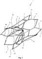
- the filter 1is movable between a collapsed delivery configuration ( Figs. 2 and 3 ) and an expanded deployed configuration ( Figs. 1 and 4 ).
- the filter 1is biased radially outwardly towards the deployed configuration.
- the filter 1comprises a proximal support hoop 3 at the proximal end of the filter 1, a distal support hoop 4 at the distal end of the filter 1, and a plurality of support struts 5 extending between the proximal support hoop 3 and the distal support hoop 4.
- the term 'proximal'will be understood to mean the end closest to a user when carrying out a procedure accessed from a femoral vein, or the caudal end.
- the term 'distal'will be understood to mean the end furthest from a user when carrying out a procedure accessed from a femoral vein, or the cranial end.
- the proximal support hoop 3extends circumferentially around the internal wall of the inferior vena cava in a zig-zag wave pattern. As illustrated in Fig. 5 , the proximal support hoop 3 comprises a plurality of elongate connector elements 10. Each connector element 10 connects a peak 11 of the wave pattern to an adjacent peak 11 of the wave pattern.
- the wave pattern of the proximal support hoop 3comprises six distal peaks 11 and six proximal peaks 11. It has been found that the filter 1 having six distal peaks 11 and six proximal peaks 11 is particularly resistant to buckling.
- the proximal support hoop 3comprises an enlarged end element at each peak 11 of the wave pattern.
- the diameter of curvature of the end element 11is greater than the distance between adjacent connector elements 10.
- the geometry of the crown tips 11allows for less rigid movement of the proximal support hoop 3 and also allows for lower strains in the proximal support hoop 3.
- Enhanced flexibility of the crown 3minimises the probability of buckling.
- the crown 3 of the filter 1offers increased torsional flexibility. This flexibility helps to minimise the probability of buckling.
- the radial dimension or wall thickness t of the proximal support hoop 3is 0.33mm in this case. It has been found that the filter 1 has a greater resistance to buckling and a higher radial force.
- the width w of each connector element 10is 0.38mm in this case.
- the filter 1 with six distal peaks 11 and six proximal peaks 11has a particularly low profile in the delivery configuration. This low profile enables larger strut thickness t and width w for a given delivery profile.
- the distal support hoop 4extends circumferentially around the internal wall of the inferior vena cava in a zig-zag wave pattern.
- the distal support hoop 4comprises a plurality of elongate connector elements 10. Each connector element 10 connects a peak 11 of the wave pattern to an adjacent peak 11 of the wave pattern.
- the wave pattern of the distal support hoop 4comprises six distal peaks 11 and six proximal peaks 11.
- the distal support hoop 4comprises an enlarged end element at each peak 11 of the wave pattern. As illustrated in Fig. 3 , in the delivery configuration the diameter of curvature of the end element 11 is greater than the distance between adjacent connector elements 10.
- the radial dimension or wall thickness of the distal support hoop 4is 0.33mm in this case.
- the width of each connector element 10is 0.38mm in this case.
- the support struts 5extend longitudinally along the internal wall of the inferior vena cava in a curve 14.
- the support struts 5connect the proximal support hoop 3 to the distal support hoop 4.
- the proximal support hoop 3, the distal support hoop 4 and the support struts 5are formed integrally.
- the proximal support hoop 3, the distal support hoop 4 and the support struts 5may be of a shape-memory material, such as NitinolTM.
- each support strut 5The radial dimension or wall thickness of each support strut 5 is 0.33mm in this case.
- the width of each support strut 5is 0.38mm in this case.
- the filter 1comprises twelve capture arms 6 for capturing thrombus passing through the inferior vena cava.
- Each capture arm 6is formed integrally with the proximal support hoop 3. As illustrated in Fig. 4 , for each distal peak 11 of the wave pattern a first capture arm 6 is connected to the proximal support hoop 3 at the distal peak 11, and a second capture arm 6 is connected to the proximal support hoop 3 at the distal peak 11.
- Each capture arm 6is movable from the capturing configuration ( Fig. 4 ) to the open configuration ( Fig. 8 ) upon elapse of the predetermined period of time.
- the capture arms 6are configured to capture thrombus passing through the inferior vena cava towards the heart and the lungs.
- the capture arms 6are configured to facilitate unrestricted blood flow.
- each capture arm 6extends to an apex 7 in a curve.
- the first capture arm 6extends from the distal peak 11 to the apex 7 in a first curve 12
- the second capture arm 6extends from the distal peak 11 to the apex 7 in a second curve 13.
- the concave portion of the first curve 12faces inwardly towards the concave portion of the second curve 13.
- the capture arms 6define a generally conically shaped capture region 8 within which thrombus may be captured. Any gaps between adjacent filter elements 6 in the filtration cone 8 are minimised.
- the filter elements 6are shape set to maximise filter efficiency.
- the term curvewill be understood to mean a smooth curve or two or more discreet straight sections.
- the filter element 6 curvaturemay be heat set to extend towards the apex in a series of two straights. It is appreciated that 2 or more discrete straights, or, a smooth curve, or, a set of smooth curves, may be employed to maximise filter efficiency.
- a perimeter routeis defined from a first distal peak 11 of the proximal support hoop 3 along a first connector element 10 to a proximal peak 11 of the proximal support hoop 3, from the proximal peak 11 along a second connector element 10 to a second distal peak 11 of the proximal support hoop 3, from the second distal peak 11 along a first support strut 5 to a first proximal peak 11 of the distal support hoop 4, from the first proximal peak 11 along a third connector element 10 to a distal peak 11 of the distal support hoop 4, from the distal peak 11 along a fourth connector element 10 to a second proximal peak 11 of the distal support hoop 4, from the second proximal peak 11 along a second support strut 5 to the first distal peak 11 of the proximal support hoop 3.
- a cellis defined within the perimeter route.
- the filter 1comprises six such cells.
- Two capture arms 6are attached to each cell in both the capturing configuration ( Fig. 4 ) and the open configuration ( Fig. 8 ). This arrangement results in a balanced cell spacing for consistent filtration pore size.
- Figs. 7(a) and 7(b)illustrate the capture arms 6 before forming into the curved shapes.
- Figs. 7(a) and 7(b)illustrate the cut pattern of Fig. 2 expanded without heat setting the capture arms 6.
- the apex 7is substantially in-line with the longitudinal axis extending through the centre of the inferior vena cava, and the capture region 8 is located in the region of the centre of the inferior vena cava.
- the capture arms 6extend in the direction of blood flow through the inferior vena cava.
- the capture arms 6are movable from the capturing configuration to the open configuration upon elapse of the predetermined period of time.
- the capture arms 6are biased towards the open configuration.
- the filter 1comprises a holder member at the distal ends of the capture arms 6 to temporarily hold the capture arms 6 in the capturing configuration until elapse of the predetermined period of time.
- the holder memberengages with each capture arm 6 to hold the capture arms 6 in the capturing configuration.
- At least part of the holder memberis biodegradable and/or bioabsorbable upon elapse of the predetermined period of time.
- the capture arms 6are free to move from the capturing configuration to the open configuration.
- the capture arms 6are not biodegradable or bioabsorbable.
- the distal end of the distal support hoop 4is located distally of the capture arms 6 and the apex 7, and the proximal end of the proximal support hoop 3 is located proximally of the capture arms 6.
- the support hoops 3, 4 and the support struts 5exert a force radially outwardly on the internal wall of the inferior vena cava. In this manner the support hoops 3, 4 and the support struts 5 support the capture arms 6 in position relative to the wall of the inferior vena cava 2.
- the maximum distance between each support strut 5 and a wall of a blood vesselmay be less than 4mm, and preferably is less than 2mm.
- the concave portion of the curve 14 of the support struts 5may face radially outwardly ( Fig. 4 ), or alternatively the support struts 5 may be straight, or alternatively the convex portion of the curve 14 of the support struts 5 may face radially outwardly.
- the convex portion of the curve 14 of the support struts 5faces radially outwardly.
- the ratio of R1:R2is in the range of from 1:1 to 1.5:1, where R1 is the distance of each support strut 5 from the central longitudinal axis of the filter 1 at the point along the support strut 5 where this distance is at a maximum, and R2 is the distance of the support strut 5 from the central longitudinal axis of the filter 1 at an end of the support strut 5 where the support strut 5 is connected to either the proximal support hoop 3 or the distal support hoop 4.
- the largest radius R1 of the convex portion of the curve 14is 17mm, and the radius R2 of the proximal support hoop 3 and the distal support hoop 4 is 15mm.
- the barrel shape of the filter 1reduces any bowing or lift-off of the support struts 5 from the blood vessel wall, increasing the contact force of the support hoops 3, 4 with the blood vessel, and improving buckling resistance.
- the filter 1is collapsed to the delivery configuration ( Figs. 2 and 3 ), and at least partially loaded into a delivery catheter.
- the delivery catheteris advanced through the inferior vena cava until the collapsed filter 1 reaches the desired location in the inferior vena cava.
- a restraining sheath of the delivery catheteris then moved proximally relative to the filter 1 to fully uncover the filter 1.
- the filter 1moves from the collapsed delivery configuration to the expanded deployed configuration ( Fig. 4 ).
- the support hoops 3, 4 and the support struts 5exert a radially outward force on the internal wall of the inferior vena cava to support the capture arms 6 in the desired position in the inferior vena cava.
- the thrombusIn the event of thrombus passing through the inferior vena cava towards the heart and the lungs, the thrombus will be captured in the capture region 8 of the filter 1. The thrombus will thus be prevented trom passing into the heart and the lungs which could otherwise lead to pulmonary embolism. The captured thrombus will gradually be broken down by the body into smaller size particles which will significantly reduce the risk of embolism.
- the holder membertemporarily holds the capture arms 6 in the capturing configuration until elapse of the predetermined period of time. Upon elapse of the predetermined period of time the holder member biodegrades/bioabsorbs. This enables the capture arms 6 to move from the capturing configuration to the open configuration ( Fig. 8 ). In the open configuration the filter 1 facilitates unrestricted blood flow.
- the support hoops 3, 4, the support struts 5 and the capture arms 6remain in the inferior vena cava.
- proximal support hoop 3 and/or the distal support hoop 4may comprise any suitable number of distal peaks and proximal peaks.
- the proximal support hoop 3 and/or the distal support hoop 4may comprise eleven distal peaks and eleven proximal peaks, or may comprise ten distal peaks and ten proximal peaks, or may comprise nine distal peaks and nine proximal peaks, or may comprise eight distal peaks and eight proximal peaks, or may comprise seven distal peaks and seven proximal peaks, or may comprise five distal peaks and five proximal peaks, or may comprise four distal peaks and four proximal peaks, or may comprise three distal peaks and three proximal peaks.
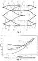
- Fig. 9illustrates the buckling behaviour of filters having a different number of peaks.
- Each filterwas placed in a blood vessel having a 16mm diameter and a crown tip 11 was pulled toward the centre of the blood vessel.
- the reaction force or force exerted by the filter against this movementis plotted on the graph of Fig. 9 .
- the force and displacement values on the graphare negative as the force is a compressive/pushing force and the crown tip 11 is moving negatively into the centre of the blood vessel.
- Fig. 9illustrates that at the largest displacement the filter having six distal peaks and six proximal peaks exerts a particularly high force against the deformation applied, and thus the filter having six distal peaks and six proximal peaks is highly resistant to buckling.
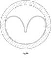
- Fig. 10illustrates buckling of a vascular filter deployed in a blood vessel.
Landscapes
- Health & Medical Sciences (AREA)
- Engineering & Computer Science (AREA)
- Biomedical Technology (AREA)
- Life Sciences & Earth Sciences (AREA)
- Transplantation (AREA)
- Oral & Maxillofacial Surgery (AREA)
- Heart & Thoracic Surgery (AREA)
- Vascular Medicine (AREA)
- Cardiology (AREA)
- Animal Behavior & Ethology (AREA)
- General Health & Medical Sciences (AREA)
- Public Health (AREA)
- Veterinary Medicine (AREA)
- Physics & Mathematics (AREA)
- Optics & Photonics (AREA)
- Surgical Instruments (AREA)
Abstract
Description
- This invention relates to a vascular filter.
WO2008/010197 (Novate Medical Ltd.) describes a vascular filter having the features of the preamble ofclaim 1.- According to the invention there is provided a vascular filter as set out in claim 1:
- By capturing the thrombus, the filter prevents the thrombus from passing to the heart or lungs, which may cause pulmonary embolism. By supporting the capture members this ensures that the capture members are maintained in the desired location in the blood vessel.
- Ideally the support member comprises an enlarged end element at a peak of the wave pattern. This arrangement results in greater flexibility, in lower strains, and in greater resistance to buckling. Most preferably in the delivery configuration the diameter of curvature of the end element is greater than the distance between adjacent connector elements. Ideally the wave pattern of the support member comprises less than eight distal peaks. Preferably a first capture member is connected to the support member at a first distal peak of the wave pattern, and a second capture member is connected to the support member at the first distal peak of the wave pattern. Ideally in the capturing configuration the first capture member extends from the first distal peak of the wave pattern towards the apex in a first curve, and the second capture member extends from the first distal peak of the wave pattern towards the apex in a second curve, the concave portion of the first curve facing inwardly towards the concave portion of the second curve. This arrangement minimises any gap between adjacent capture members, and thus improves filter efficiency.
- Preferably the support member is configured to extend longitudinally in a curve. This arrangement minimises any bowing or lift-off of the support member from the wall of the blood vessel. Thus the contact force between the support member and the blood vessel is maximised which enhances resistance to buckling.
- In the capturing configuration the maximum distance between the support member and a wall of a blood vessel may be less than 4mm. In the capturing configuration the maximum distance between the support member and a wall of a blood vessel may be less than 2mm.
- In one embodiment the radial dimension of the support member is greater than 0.20mm. This arrangement results in greater resistance to buckling. Preferably the radial dimension of the support member is greater than 0.25mm. Ideally the radial dimension of the support member is greater than 0.30mm.
- In another embodiment at least part of the support member comprises one or more elongate elements, the width of at least one of the elongate elements being greater than 0.25mm. This arrangement results in greater resistance to buckling. Preferably the width of the elongate element is greater than 0.30mm. Ideally the width of the elongate element is greater than 0.35mm.
- The invention will be more clearly understood from the following description of an embodiment thereof, given by way of example only, with reference to the accompanying drawings, in which:
Fig. 1 is an isometric view of a vascular filter according to the invention in a deployed capturing configuration,Fig. 2 is a developed side view of the vascular filter ofFig. 1 in a delivery configuration,Fig. 3 is an enlarged developed side view of part of the vascular filter ofFig. 2 in the delivery configuration,Fig. 4 is a side view of the vascular filter ofFig. 1 in the deployed capturing configuration,Fig. 5 is an enlarged side view of part of the vascular filter ofFig. 4 in the deployed capturing configuration,Fig. 6 is an end view of the vascular filter ofFig. 1 in the deployed capturing configuration,Fig. 7 is an enlarged end view of part of the vascular filter ofFig. 6 in the deployed capturing configuration,Fig. 7(a) is an end view of the vascular filter ofFig. 1 during manufacture,Fig. 7(b) is an enlarged end view of part of the vascular filter ofFig. 7(a) during manufacture,Fig. 8 is a side view of the vascular filter ofFig. 1 in a deployed open configuration,Fig. 9 is a graph of force versus displacement, andFig. 10 is an end view illustrating buckling of a vascular filter.- Referring to the drawings there is illustrated a
vascular filter 1 according to the invention. Thevascular filter 1 is suitable for use as an inferior vena cava filter in the inferior vena cava. Thefilter 1 is movable from a capturing configuration (Fig. 4 ) to an open configuration (Fig. 8 ) upon elapse of a predetermined period of time. In the capturing configuration thefilter 1 is configured to capture thrombus passing through the inferior vena cava towards the heart and the lungs. Thefilter 1 may thus be used to prevent pulmonary embolism. In the open configuration thefilter 1 is configured to facilitate unrestricted blood flow. - The
filter 1 is movable between a collapsed delivery configuration (Figs. 2 and 3 ) and an expanded deployed configuration (Figs. 1 and4 ). Thefilter 1 is biased radially outwardly towards the deployed configuration. - As illustrated in
Fig. 1 , thefilter 1 comprises aproximal support hoop 3 at the proximal end of thefilter 1, adistal support hoop 4 at the distal end of thefilter 1, and a plurality ofsupport struts 5 extending between theproximal support hoop 3 and thedistal support hoop 4. - In this patent specification, the term 'proximal' will be understood to mean the end closest to a user when carrying out a procedure accessed from a femoral vein, or the caudal end. Similarly the term 'distal' will be understood to mean the end furthest from a user when carrying out a procedure accessed from a femoral vein, or the cranial end.
- The
proximal support hoop 3 extends circumferentially around the internal wall of the inferior vena cava in a zig-zag wave pattern. As illustrated inFig. 5 , theproximal support hoop 3 comprises a plurality ofelongate connector elements 10. Eachconnector element 10 connects apeak 11 of the wave pattern to anadjacent peak 11 of the wave pattern. - In this case the wave pattern of the
proximal support hoop 3 comprises sixdistal peaks 11 and sixproximal peaks 11. It has been found that thefilter 1 having sixdistal peaks 11 and sixproximal peaks 11 is particularly resistant to buckling. - The
proximal support hoop 3 comprises an enlarged end element at eachpeak 11 of the wave pattern. In the delivery configuration the diameter of curvature of theend element 11 is greater than the distance betweenadjacent connector elements 10. The geometry of thecrown tips 11 allows for less rigid movement of theproximal support hoop 3 and also allows for lower strains in theproximal support hoop 3. Enhanced flexibility of thecrown 3 minimises the probability of buckling. Thecrown 3 of thefilter 1 offers increased torsional flexibility. This flexibility helps to minimise the probability of buckling. - As illustrated in
Fig. 5 , the radial dimension or wall thickness t of theproximal support hoop 3 is 0.33mm in this case. It has been found that thefilter 1 has a greater resistance to buckling and a higher radial force. The width w of eachconnector element 10 is 0.38mm in this case. Thefilter 1 with sixdistal peaks 11 and sixproximal peaks 11 has a particularly low profile in the delivery configuration. This low profile enables larger strut thickness t and width w for a given delivery profile. - Similarly the
distal support hoop 4 extends circumferentially around the internal wall of the inferior vena cava in a zig-zag wave pattern. Thedistal support hoop 4 comprises a plurality ofelongate connector elements 10. Eachconnector element 10 connects apeak 11 of the wave pattern to anadjacent peak 11 of the wave pattern. - In this case the wave pattern of the
distal support hoop 4 comprises sixdistal peaks 11 and sixproximal peaks 11. - The
distal support hoop 4 comprises an enlarged end element at eachpeak 11 of the wave pattern. As illustrated inFig. 3 , in the delivery configuration the diameter of curvature of theend element 11 is greater than the distance betweenadjacent connector elements 10. - The radial dimension or wall thickness of the
distal support hoop 4 is 0.33mm in this case. The width of eachconnector element 10 is 0.38mm in this case. - The support struts 5 extend longitudinally along the internal wall of the inferior vena cava in a
curve 14. The support struts 5 connect theproximal support hoop 3 to thedistal support hoop 4. In this case theproximal support hoop 3, thedistal support hoop 4 and the support struts 5 are formed integrally. Theproximal support hoop 3, thedistal support hoop 4 and the support struts 5 may be of a shape-memory material, such as Nitinol™. - The radial dimension or wall thickness of each
support strut 5 is 0.33mm in this case. The width of eachsupport strut 5 is 0.38mm in this case. - As illustrated in
Fig. 1 , thefilter 1 comprises twelvecapture arms 6 for capturing thrombus passing through the inferior vena cava. - Each
capture arm 6 is formed integrally with theproximal support hoop 3. As illustrated inFig. 4 , for eachdistal peak 11 of the wave pattern afirst capture arm 6 is connected to theproximal support hoop 3 at thedistal peak 11, and asecond capture arm 6 is connected to theproximal support hoop 3 at thedistal peak 11. - Each
capture arm 6 is movable from the capturing configuration (Fig. 4 ) to the open configuration (Fig. 8 ) upon elapse of the predetermined period of time. In the capturing configuration thecapture arms 6 are configured to capture thrombus passing through the inferior vena cava towards the heart and the lungs. In the open configuration thecapture arms 6 are configured to facilitate unrestricted blood flow. - In the capturing configuration each
capture arm 6 extends to an apex 7 in a curve. As illustrated inFig. 4 , for eachdistal peak 11 of the wave pattern thefirst capture arm 6 extends from thedistal peak 11 to the apex 7 in afirst curve 12, and thesecond capture arm 6 extends from thedistal peak 11 to the apex 7 in asecond curve 13. The concave portion of thefirst curve 12 faces inwardly towards the concave portion of thesecond curve 13. In this manner thecapture arms 6 define a generally conically shapedcapture region 8 within which thrombus may be captured. Any gaps betweenadjacent filter elements 6 in thefiltration cone 8 are minimised. Thefilter elements 6 are shape set to maximise filter efficiency. - In this specification, the term curve will be understood to mean a smooth curve or two or more discreet straight sections. For example, the
filter element 6 curvature may be heat set to extend towards the apex in a series of two straights. It is appreciated that 2 or more discrete straights, or, a smooth curve, or, a set of smooth curves, may be employed to maximise filter efficiency. - A perimeter route is defined from a first
distal peak 11 of theproximal support hoop 3 along afirst connector element 10 to aproximal peak 11 of theproximal support hoop 3, from theproximal peak 11 along asecond connector element 10 to a seconddistal peak 11 of theproximal support hoop 3, from the seconddistal peak 11 along afirst support strut 5 to a firstproximal peak 11 of thedistal support hoop 4, from the firstproximal peak 11 along athird connector element 10 to adistal peak 11 of thedistal support hoop 4, from thedistal peak 11 along afourth connector element 10 to a secondproximal peak 11 of thedistal support hoop 4, from the secondproximal peak 11 along asecond support strut 5 to the firstdistal peak 11 of theproximal support hoop 3. A cell is defined within the perimeter route. Thefilter 1 comprises six such cells. Twocapture arms 6 are attached to each cell in both the capturing configuration (Fig. 4 ) and the open configuration (Fig. 8 ). This arrangement results in a balanced cell spacing for consistent filtration pore size. - During manufacture the
capture arms 6 are formed into the curved shapes.Figs. 7(a) and 7(b) illustrate thecapture arms 6 before forming into the curved shapes.Figs. 7(a) and 7(b) illustrate the cut pattern ofFig. 2 expanded without heat setting thecapture arms 6. - When the
filter 1 is deployed in the inferior vena cava, theapex 7 is substantially in-line with the longitudinal axis extending through the centre of the inferior vena cava, and thecapture region 8 is located in the region of the centre of the inferior vena cava. When thefilter 1 is deployed in the inferior vena cava, thecapture arms 6 extend in the direction of blood flow through the inferior vena cava. - The
capture arms 6 are movable from the capturing configuration to the open configuration upon elapse of the predetermined period of time. Thecapture arms 6 are biased towards the open configuration. - The
filter 1 comprises a holder member at the distal ends of thecapture arms 6 to temporarily hold thecapture arms 6 in the capturing configuration until elapse of the predetermined period of time. The holder member engages with eachcapture arm 6 to hold thecapture arms 6 in the capturing configuration. At least part of the holder member is biodegradable and/or bioabsorbable upon elapse of the predetermined period of time. Upon biodegrading/bioabsorbing of the holder member, thecapture arms 6 are free to move from the capturing configuration to the open configuration. Thecapture arms 6 are not biodegradable or bioabsorbable. - The distal end of the
distal support hoop 4 is located distally of thecapture arms 6 and the apex 7, and the proximal end of theproximal support hoop 3 is located proximally of thecapture arms 6. - When the
filter 1 is deployed in the inferior vena cava, thesupport hoops support hoops capture arms 6 in position relative to the wall of the inferior vena cava 2. - In the capturing configuration the maximum distance between each
support strut 5 and a wall of a blood vessel may be less than 4mm, and preferably is less than 2mm. In the capturing configuration the concave portion of thecurve 14 of the support struts 5 may face radially outwardly (Fig. 4 ), or alternatively the support struts 5 may be straight, or alternatively the convex portion of thecurve 14 of the support struts 5 may face radially outwardly. - As illustrated in
Fig. 8 , when the filter is deployed externally of a blood vessel, in the open configuration the convex portion of thecurve 14 of the support struts 5 faces radially outwardly. In the open configuration the ratio of R1:R2 is in the range of from 1:1 to 1.5:1, where
R1 is the distance of eachsupport strut 5 from the central longitudinal axis of thefilter 1 at the point along thesupport strut 5 where this distance is at a maximum, and
R2 is the distance of thesupport strut 5 from the central longitudinal axis of thefilter 1 at an end of thesupport strut 5 where thesupport strut 5 is connected to either theproximal support hoop 3 or thedistal support hoop 4. - In this case the largest radius R1 of the convex portion of the
curve 14 is 17mm, and the radius R2 of theproximal support hoop 3 and thedistal support hoop 4 is 15mm. The barrel shape of thefilter 1 reduces any bowing or lift-off of the support struts 5 from the blood vessel wall, increasing the contact force of thesupport hoops - In use the
filter 1 is collapsed to the delivery configuration (Figs. 2 and 3 ), and at least partially loaded into a delivery catheter. The delivery catheter is advanced through the inferior vena cava until thecollapsed filter 1 reaches the desired location in the inferior vena cava. A restraining sheath of the delivery catheter is then moved proximally relative to thefilter 1 to fully uncover thefilter 1. Due to the biasing nature of thefilter 1, thefilter 1 moves from the collapsed delivery configuration to the expanded deployed configuration (Fig. 4 ). In the deployed configuration, thesupport hoops capture arms 6 in the desired position in the inferior vena cava. - In the event of thrombus passing through the inferior vena cava towards the heart and the lungs, the thrombus will be captured in the
capture region 8 of thefilter 1. The thrombus will thus be prevented trom passing into the heart and the lungs which could otherwise lead to pulmonary embolism. The captured thrombus will gradually be broken down by the body into smaller size particles which will significantly reduce the risk of embolism. - The holder member temporarily holds the
capture arms 6 in the capturing configuration until elapse of the predetermined period of time. Upon elapse of the predetermined period of time the holder member biodegrades/bioabsorbs. This enables thecapture arms 6 to move from the capturing configuration to the open configuration (Fig. 8 ). In the open configuration thefilter 1 facilitates unrestricted blood flow. Thesupport hoops capture arms 6 remain in the inferior vena cava. - It will be appreciated that the
proximal support hoop 3 and/or thedistal support hoop 4 may comprise any suitable number of distal peaks and proximal peaks. For example theproximal support hoop 3 and/or thedistal support hoop 4 may comprise eleven distal peaks and eleven proximal peaks, or may comprise ten distal peaks and ten proximal peaks, or may comprise nine distal peaks and nine proximal peaks, or may comprise eight distal peaks and eight proximal peaks, or may comprise seven distal peaks and seven proximal peaks, or may comprise five distal peaks and five proximal peaks, or may comprise four distal peaks and four proximal peaks, or may comprise three distal peaks and three proximal peaks. Fig. 9 illustrates the buckling behaviour of filters having a different number of peaks. Each filter was placed in a blood vessel having a 16mm diameter and acrown tip 11 was pulled toward the centre of the blood vessel. The reaction force or force exerted by the filter against this movement is plotted on the graph ofFig. 9 . The force and displacement values on the graph are negative as the force is a compressive/pushing force and thecrown tip 11 is moving negatively into the centre of the blood vessel.Fig. 9 illustrates that at the largest displacement the filter having six distal peaks and six proximal peaks exerts a particularly high force against the deformation applied, and thus the filter having six distal peaks and six proximal peaks is highly resistant to buckling.Fig. 10 illustrates buckling of a vascular filter deployed in a blood vessel.- The invention is not limited to the embodiment hereinbefore described, with reference to the accompanying drawings, which may be varied in construction and detail.
Claims (12)
- A vascular filter (1) comprising:capture members (6) for capturing thrombus passing through a blood vessel, wherein the capture members (6) are movable from a capturing configuration to an open configuration, in the capturing configuration the capture members being configured to capture thrombus passing through a blood vessel, in the open configuration the capture members being configured to facilitate unrestricted blood flow;support members (3, 4, 5) for supporting the capture members relative to a wall of the blood vessel, and being movable between a delivery configuration and a deployed configuration; andwherein the support members comprise a proximal hoop in a wave pattern, a distal hoop in a wave pattern, and struts extending longitudinally along the wall of a blood vessel interconnecting the proximal and distal hoops;wherein the proximal and distal hoops each comprises a plurality of connector elements (4, 10), each connector element connecting a peak of the wave pattern to an adjacent peak of the wave pattern;wherein the capture members are connected to the support member at or adjacent to a distal peak of the proximal hoop;characterized in that,the proximal hoop comprises eight or less proximal peaks and eight or less distal peaks, and the distal hoop comprises eight or less proximal peaks and eight or less distal peaks.
- A filter as claimed in claim 1, wherein the capture members (6) extend towards an apex in curves in which a concave portion of a curve of a first capture member faces towards the concave portion of a curve of a second capture member and wherein, for each distal peak of the proximal support hoop, a first capture member is connected to the support members at or adjacent to the distal peak and a second capture member is also connected at or adjacent to the same distal peak, the capture members not overlapping each other as viewed in a longitudinal axis of the filter.
- A filter as claimed in any preceding claim, wherein at least one hoop comprises an enlarged end element (11) at a peak of the wave pattern.
- A filter as claimed in claim 3, wherein in the delivery configuration the diameter of curvature of the end element (11) is greater than the distance between adjacent connector elements.
- A filter as claimed in any preceding claim, wherein the hoops each comprises less than eight proximal peaks and less than eight distal peaks.
- A filter as claimed in claim 5, wherein the hoops each comprises six proximal peaks and six distal peaks.
- A filter as claimed in any preceding claim, wherein in the capturing configuration the maximum distance between the support member and a wall of a blood vessel is less than 4mm.
- A filter as claimed in any preceding claim, wherein the radial dimension of a connector element is greater than 0.25mm.
- A filter as claimed in claim 8, wherein the radial dimension of a connector element is greater than 0.30mm.
- A filter as claimed in any of claims 1 to 9, wherein the width of at least one connector element is greater than 0.25mm.
- A filter as claimed in claim 10, wherein the width of the element is greater than 0.30mm.
- A filter as claimed in claim 11, wherein the width of the element is greater than 0.35mm.
Applications Claiming Priority (2)
| Application Number | Priority Date | Filing Date | Title |
|---|---|---|---|
| IE20090040 | 2009-01-16 | ||
| EP10394001AEP2208479B1 (en) | 2009-01-16 | 2010-01-15 | A vascular filter |
Related Parent Applications (2)
| Application Number | Title | Priority Date | Filing Date |
|---|---|---|---|
| EP10394001ADivisionEP2208479B1 (en) | 2009-01-16 | 2010-01-15 | A vascular filter |
| EP10394001.1Division | 2010-01-15 |
Publications (4)
| Publication Number | Publication Date |
|---|---|
| EP2460491A2 EP2460491A2 (en) | 2012-06-06 |
| EP2460491A3 EP2460491A3 (en) | 2012-08-15 |
| EP2460491B1true EP2460491B1 (en) | 2017-04-12 |
| EP2460491B2 EP2460491B2 (en) | 2023-11-29 |
Family
ID=42083205
Family Applications (2)
| Application Number | Title | Priority Date | Filing Date |
|---|---|---|---|
| EP12075021.1AActiveEP2460491B2 (en) | 2009-01-16 | 2010-01-15 | A vascular filter |
| EP10394001ANot-in-forceEP2208479B1 (en) | 2009-01-16 | 2010-01-15 | A vascular filter |
Family Applications After (1)
| Application Number | Title | Priority Date | Filing Date |
|---|---|---|---|
| EP10394001ANot-in-forceEP2208479B1 (en) | 2009-01-16 | 2010-01-15 | A vascular filter |
Country Status (2)
| Country | Link |
|---|---|
| EP (2) | EP2460491B2 (en) |
| AT (1) | ATE556669T1 (en) |
Families Citing this family (9)
| Publication number | Priority date | Publication date | Assignee | Title |
|---|---|---|---|---|
| US20110152918A1 (en) | 2009-12-23 | 2011-06-23 | Pavilion Medical Innovations | Reversible Vascular Filter Devices and Methods for Using Same |
| JP6426088B2 (en) | 2012-07-25 | 2018-11-21 | ノベート・メディカル・リミテッド | Vascular filter device |
| US10076398B2 (en) | 2012-12-27 | 2018-09-18 | Cook Medical Technologies Llc | Biodegradable filter |
| WO2014140088A2 (en) | 2013-03-15 | 2014-09-18 | Novate Medical Limited | A vascular filter device |
| CN106491238B (en)* | 2015-09-07 | 2020-06-16 | 上海微创心脉医疗科技股份有限公司 | Filter device |
| CN106491239B (en)* | 2015-09-08 | 2018-12-11 | 微创心脉医疗科技(上海)有限公司 | Filter unit |
| GB2552361B (en) | 2016-07-21 | 2019-12-25 | Cook Medical Technologies Llc | Implantable medical device and method |
| CN108309506B (en)* | 2018-03-19 | 2023-10-13 | 威海维心医疗设备有限公司 | vena cava filter |
| CN116211398B (en)* | 2023-03-16 | 2023-12-15 | 上海腾复医疗科技有限公司 | Bolt breaking filter |
Citations (10)
| Publication number | Priority date | Publication date | Assignee | Title |
|---|---|---|---|---|
| US5375612A (en) | 1992-04-07 | 1994-12-27 | B. Braun Celsa | Possibly absorbable blood filter |
| US5383887A (en) | 1992-12-28 | 1995-01-24 | Celsa Lg | Device for selectively forming a temporary blood filter |
| US6214025B1 (en) | 1994-11-30 | 2001-04-10 | Boston Scientific Corporation | Self-centering, self-expanding and retrievable vena cava filter |
| WO2005023149A2 (en) | 2003-09-03 | 2005-03-17 | Bolton Medical, Inc. | Stent graft, stent graft delivery system and kit and method for implanting the stent graft |
| WO2005102437A2 (en) | 2004-04-16 | 2005-11-03 | Cordis Corporation | Asymmetrical medical filter |
| US20060058836A1 (en) | 2004-09-10 | 2006-03-16 | Arani Bose | System and method for treating ischemic stroke |
| US20070112372A1 (en) | 2005-11-17 | 2007-05-17 | Stephen Sosnowski | Biodegradable vascular filter |
| WO2008010197A2 (en) | 2006-07-19 | 2008-01-24 | Novate Medical Limited | A vascular filter |
| WO2008066881A1 (en) | 2006-11-29 | 2008-06-05 | Amir Belson | Embolic protection device |
| US20080281396A1 (en)* | 2007-05-09 | 2008-11-13 | Japan Science And Technology Agency | Guide wire and stent |
Family Cites Families (6)
| Publication number | Priority date | Publication date | Assignee | Title |
|---|---|---|---|---|
| AU2001241603A1 (en) | 2000-02-23 | 2001-09-03 | Boston Scientific Limited | Intravascular filtering devices and methods |
| US8109987B2 (en) | 2003-04-14 | 2012-02-07 | Tryton Medical, Inc. | Method of treating a lumenal bifurcation |
| US7704266B2 (en)* | 2004-01-22 | 2010-04-27 | Rex Medical, L.P. | Vein filter |
| US20060025852A1 (en) | 2004-08-02 | 2006-02-02 | Armstrong Joseph R | Bioabsorbable self-expanding endolumenal devices |
| US20080188887A1 (en) | 2007-02-07 | 2008-08-07 | Stanley Batiste | Removable vascular filter and method of filter placement |
| US9901434B2 (en) | 2007-02-27 | 2018-02-27 | Cook Medical Technologies Llc | Embolic protection device including a Z-stent waist band |
- 2010
- 2010-01-15ATAT10394001Tpatent/ATE556669T1/enactive
- 2010-01-15EPEP12075021.1Apatent/EP2460491B2/enactiveActive
- 2010-01-15EPEP10394001Apatent/EP2208479B1/ennot_activeNot-in-force
Patent Citations (10)
| Publication number | Priority date | Publication date | Assignee | Title |
|---|---|---|---|---|
| US5375612A (en) | 1992-04-07 | 1994-12-27 | B. Braun Celsa | Possibly absorbable blood filter |
| US5383887A (en) | 1992-12-28 | 1995-01-24 | Celsa Lg | Device for selectively forming a temporary blood filter |
| US6214025B1 (en) | 1994-11-30 | 2001-04-10 | Boston Scientific Corporation | Self-centering, self-expanding and retrievable vena cava filter |
| WO2005023149A2 (en) | 2003-09-03 | 2005-03-17 | Bolton Medical, Inc. | Stent graft, stent graft delivery system and kit and method for implanting the stent graft |
| WO2005102437A2 (en) | 2004-04-16 | 2005-11-03 | Cordis Corporation | Asymmetrical medical filter |
| US20060058836A1 (en) | 2004-09-10 | 2006-03-16 | Arani Bose | System and method for treating ischemic stroke |
| US20070112372A1 (en) | 2005-11-17 | 2007-05-17 | Stephen Sosnowski | Biodegradable vascular filter |
| WO2008010197A2 (en) | 2006-07-19 | 2008-01-24 | Novate Medical Limited | A vascular filter |
| WO2008066881A1 (en) | 2006-11-29 | 2008-06-05 | Amir Belson | Embolic protection device |
| US20080281396A1 (en)* | 2007-05-09 | 2008-11-13 | Japan Science And Technology Agency | Guide wire and stent |
Non-Patent Citations (1)
| Title |
|---|
| "Shorter Oxford English Dictionary on Historical Principles Sixth edition", 2007, article "movable/mover", pages: 1853, XP055623804 |
Also Published As
| Publication number | Publication date |
|---|---|
| EP2460491A2 (en) | 2012-06-06 |
| EP2208479A1 (en) | 2010-07-21 |
| ATE556669T1 (en) | 2012-05-15 |
| EP2460491B2 (en) | 2023-11-29 |
| EP2208479B1 (en) | 2012-05-09 |
| EP2460491A3 (en) | 2012-08-15 |
Similar Documents
| Publication | Publication Date | Title |
|---|---|---|
| US20210322147A1 (en) | Vascular filter | |
| EP2460491B1 (en) | A vascular filter | |
| US12089863B2 (en) | Multi-pivot thrombectomy device | |
| US8025675B2 (en) | Temporary filter device | |
| EP2604222B1 (en) | Vena cava filter with bidirectional retrieval | |
| EP1737385B1 (en) | Removable vena cava filter with anchoring feature for reduced trauma | |
| EP2192878B1 (en) | Flexible stent with torque-absorbing connectors | |
| DK1737383T3 (en) | Removable VENA CAVA FILTER by bearers FOR IMPROVED COLLECTION AND FEED | |
| US20110082492A1 (en) | Embolic protection device | |
| EP2926768B1 (en) | Vascular filter | |
| CN112842467A (en) | Thrombus removing device | |
| AU2005232367B2 (en) | A self centering vena cava filter | |
| CN211834882U (en) | Expandable stent for maintaining open state of vessel wall and kit thereof |
Legal Events
| Date | Code | Title | Description |
|---|---|---|---|
| PUAI | Public reference made under article 153(3) epc to a published international application that has entered the european phase | Free format text:ORIGINAL CODE: 0009012 | |
| AC | Divisional application: reference to earlier application | Ref document number:2208479 Country of ref document:EP Kind code of ref document:P | |
| AK | Designated contracting states | Kind code of ref document:A2 Designated state(s):AT BE BG CH CY CZ DE DK EE ES FI FR GB GR HR HU IE IS IT LI LT LU LV MC MK MT NL NO PL PT RO SE SI SK SM TR | |
| PUAL | Search report despatched | Free format text:ORIGINAL CODE: 0009013 | |
| AK | Designated contracting states | Kind code of ref document:A3 Designated state(s):AT BE BG CH CY CZ DE DK EE ES FI FR GB GR HR HU IE IS IT LI LT LU LV MC MK MT NL NO PL PT RO SE SI SK SM TR | |
| RAP1 | Party data changed (applicant data changed or rights of an application transferred) | Owner name:NOVATE MEDICAL LTD. | |
| RIC1 | Information provided on ipc code assigned before grant | Ipc:A61F 2/01 20060101AFI20120712BHEP | |
| 17P | Request for examination filed | Effective date:20130206 | |
| 17Q | First examination report despatched | Effective date:20150921 | |
| 111Z | Information provided on other rights and legal means of execution | Free format text:AT BE BG CH CY CZ DE DK EE ES FI FR GB GR HR HU IE IS IT LT LU LV MC MK MT NL NO PL PT RO SE SI SK SM TR Effective date:20151203 | |
| GRAP | Despatch of communication of intention to grant a patent | Free format text:ORIGINAL CODE: EPIDOSNIGR1 | |
| STAA | Information on the status of an ep patent application or granted ep patent | Free format text:STATUS: GRANT OF PATENT IS INTENDED | |
| RIC1 | Information provided on ipc code assigned before grant | Ipc:A61F 2/915 20130101ALI20161005BHEP Ipc:A61F 2/01 20060101AFI20161005BHEP | |
| INTG | Intention to grant announced | Effective date:20161103 | |
| GRAS | Grant fee paid | Free format text:ORIGINAL CODE: EPIDOSNIGR3 | |
| GRAA | (expected) grant | Free format text:ORIGINAL CODE: 0009210 | |
| STAA | Information on the status of an ep patent application or granted ep patent | Free format text:STATUS: THE PATENT HAS BEEN GRANTED | |
| AC | Divisional application: reference to earlier application | Ref document number:2208479 Country of ref document:EP Kind code of ref document:P | |
| AK | Designated contracting states | Kind code of ref document:B1 Designated state(s):AT BE BG CH CY CZ DE DK EE ES FI FR GB GR HR HU IE IS IT LI LT LU LV MC MK MT NL NO PL PT RO SE SI SK SM TR | |
| REG | Reference to a national code | Ref country code:GB Ref legal event code:FG4D | |
| REG | Reference to a national code | Ref country code:CH Ref legal event code:EP | |
| REG | Reference to a national code | Ref country code:IE Ref legal event code:FG4D Ref country code:NL Ref legal event code:FP | |
| REG | Reference to a national code | Ref country code:AT Ref legal event code:REF Ref document number:883103 Country of ref document:AT Kind code of ref document:T Effective date:20170515 | |
| REG | Reference to a national code | Ref country code:DE Ref legal event code:R096 Ref document number:602010041578 Country of ref document:DE | |
| REG | Reference to a national code | Ref country code:LT Ref legal event code:MG4D | |
| REG | Reference to a national code | Ref country code:AT Ref legal event code:MK05 Ref document number:883103 Country of ref document:AT Kind code of ref document:T Effective date:20170412 | |
| PG25 | Lapsed in a contracting state [announced via postgrant information from national office to epo] | Ref country code:HR Free format text:LAPSE BECAUSE OF FAILURE TO SUBMIT A TRANSLATION OF THE DESCRIPTION OR TO PAY THE FEE WITHIN THE PRESCRIBED TIME-LIMIT Effective date:20170412 Ref country code:LT Free format text:LAPSE BECAUSE OF FAILURE TO SUBMIT A TRANSLATION OF THE DESCRIPTION OR TO PAY THE FEE WITHIN THE PRESCRIBED TIME-LIMIT Effective date:20170412 Ref country code:FI Free format text:LAPSE BECAUSE OF FAILURE TO SUBMIT A TRANSLATION OF THE DESCRIPTION OR TO PAY THE FEE WITHIN THE PRESCRIBED TIME-LIMIT Effective date:20170412 Ref country code:AT Free format text:LAPSE BECAUSE OF FAILURE TO SUBMIT A TRANSLATION OF THE DESCRIPTION OR TO PAY THE FEE WITHIN THE PRESCRIBED TIME-LIMIT Effective date:20170412 Ref country code:NO Free format text:LAPSE BECAUSE OF FAILURE TO SUBMIT A TRANSLATION OF THE DESCRIPTION OR TO PAY THE FEE WITHIN THE PRESCRIBED TIME-LIMIT Effective date:20170712 Ref country code:GR Free format text:LAPSE BECAUSE OF FAILURE TO SUBMIT A TRANSLATION OF THE DESCRIPTION OR TO PAY THE FEE WITHIN THE PRESCRIBED TIME-LIMIT Effective date:20170713 Ref country code:ES Free format text:LAPSE BECAUSE OF FAILURE TO SUBMIT A TRANSLATION OF THE DESCRIPTION OR TO PAY THE FEE WITHIN THE PRESCRIBED TIME-LIMIT Effective date:20170412 | |
| PG25 | Lapsed in a contracting state [announced via postgrant information from national office to epo] | Ref country code:SE Free format text:LAPSE BECAUSE OF FAILURE TO SUBMIT A TRANSLATION OF THE DESCRIPTION OR TO PAY THE FEE WITHIN THE PRESCRIBED TIME-LIMIT Effective date:20170412 Ref country code:PL Free format text:LAPSE BECAUSE OF FAILURE TO SUBMIT A TRANSLATION OF THE DESCRIPTION OR TO PAY THE FEE WITHIN THE PRESCRIBED TIME-LIMIT Effective date:20170412 Ref country code:LV Free format text:LAPSE BECAUSE OF FAILURE TO SUBMIT A TRANSLATION OF THE DESCRIPTION OR TO PAY THE FEE WITHIN THE PRESCRIBED TIME-LIMIT Effective date:20170412 Ref country code:BG Free format text:LAPSE BECAUSE OF FAILURE TO SUBMIT A TRANSLATION OF THE DESCRIPTION OR TO PAY THE FEE WITHIN THE PRESCRIBED TIME-LIMIT Effective date:20170712 Ref country code:IS Free format text:LAPSE BECAUSE OF FAILURE TO SUBMIT A TRANSLATION OF THE DESCRIPTION OR TO PAY THE FEE WITHIN THE PRESCRIBED TIME-LIMIT Effective date:20170812 | |
| REG | Reference to a national code | Ref country code:DE Ref legal event code:R026 Ref document number:602010041578 Country of ref document:DE | |
| PLBI | Opposition filed | Free format text:ORIGINAL CODE: 0009260 | |
| PG25 | Lapsed in a contracting state [announced via postgrant information from national office to epo] | Ref country code:CZ Free format text:LAPSE BECAUSE OF FAILURE TO SUBMIT A TRANSLATION OF THE DESCRIPTION OR TO PAY THE FEE WITHIN THE PRESCRIBED TIME-LIMIT Effective date:20170412 Ref country code:DK Free format text:LAPSE BECAUSE OF FAILURE TO SUBMIT A TRANSLATION OF THE DESCRIPTION OR TO PAY THE FEE WITHIN THE PRESCRIBED TIME-LIMIT Effective date:20170412 Ref country code:RO Free format text:LAPSE BECAUSE OF FAILURE TO SUBMIT A TRANSLATION OF THE DESCRIPTION OR TO PAY THE FEE WITHIN THE PRESCRIBED TIME-LIMIT Effective date:20170412 Ref country code:SK Free format text:LAPSE BECAUSE OF FAILURE TO SUBMIT A TRANSLATION OF THE DESCRIPTION OR TO PAY THE FEE WITHIN THE PRESCRIBED TIME-LIMIT Effective date:20170412 Ref country code:EE Free format text:LAPSE BECAUSE OF FAILURE TO SUBMIT A TRANSLATION OF THE DESCRIPTION OR TO PAY THE FEE WITHIN THE PRESCRIBED TIME-LIMIT Effective date:20170412 | |
| PLAX | Notice of opposition and request to file observation + time limit sent | Free format text:ORIGINAL CODE: EPIDOSNOBS2 | |
| 26 | Opposition filed | Opponent name:COOK MEDICAL TECHNOLOGIES LLC Effective date:20180111 | |
| PG25 | Lapsed in a contracting state [announced via postgrant information from national office to epo] | Ref country code:SM Free format text:LAPSE BECAUSE OF FAILURE TO SUBMIT A TRANSLATION OF THE DESCRIPTION OR TO PAY THE FEE WITHIN THE PRESCRIBED TIME-LIMIT Effective date:20170412 Ref country code:IT Free format text:LAPSE BECAUSE OF FAILURE TO SUBMIT A TRANSLATION OF THE DESCRIPTION OR TO PAY THE FEE WITHIN THE PRESCRIBED TIME-LIMIT Effective date:20170412 | |
| PG25 | Lapsed in a contracting state [announced via postgrant information from national office to epo] | Ref country code:SI Free format text:LAPSE BECAUSE OF FAILURE TO SUBMIT A TRANSLATION OF THE DESCRIPTION OR TO PAY THE FEE WITHIN THE PRESCRIBED TIME-LIMIT Effective date:20170412 | |
| PLBB | Reply of patent proprietor to notice(s) of opposition received | Free format text:ORIGINAL CODE: EPIDOSNOBS3 | |
| REG | Reference to a national code | Ref country code:CH Ref legal event code:PL | |
| PG25 | Lapsed in a contracting state [announced via postgrant information from national office to epo] | Ref country code:LU Free format text:LAPSE BECAUSE OF NON-PAYMENT OF DUE FEES Effective date:20180115 Ref country code:FR Free format text:LAPSE BECAUSE OF NON-PAYMENT OF DUE FEES Effective date:20180131 | |
| REG | Reference to a national code | Ref country code:FR Ref legal event code:ST Effective date:20180928 | |
| REG | Reference to a national code | Ref country code:BE Ref legal event code:MM Effective date:20180131 | |
| PG25 | Lapsed in a contracting state [announced via postgrant information from national office to epo] | Ref country code:BE Free format text:LAPSE BECAUSE OF NON-PAYMENT OF DUE FEES Effective date:20180131 Ref country code:LI Free format text:LAPSE BECAUSE OF NON-PAYMENT OF DUE FEES Effective date:20180131 Ref country code:CH Free format text:LAPSE BECAUSE OF NON-PAYMENT OF DUE FEES Effective date:20180131 | |
| PG25 | Lapsed in a contracting state [announced via postgrant information from national office to epo] | Ref country code:MC Free format text:LAPSE BECAUSE OF FAILURE TO SUBMIT A TRANSLATION OF THE DESCRIPTION OR TO PAY THE FEE WITHIN THE PRESCRIBED TIME-LIMIT Effective date:20170412 | |
| APBM | Appeal reference recorded | Free format text:ORIGINAL CODE: EPIDOSNREFNO | |
| APBP | Date of receipt of notice of appeal recorded | Free format text:ORIGINAL CODE: EPIDOSNNOA2O | |
| APAH | Appeal reference modified | Free format text:ORIGINAL CODE: EPIDOSCREFNO | |
| APBM | Appeal reference recorded | Free format text:ORIGINAL CODE: EPIDOSNREFNO | |
| APBP | Date of receipt of notice of appeal recorded | Free format text:ORIGINAL CODE: EPIDOSNNOA2O | |
| APBQ | Date of receipt of statement of grounds of appeal recorded | Free format text:ORIGINAL CODE: EPIDOSNNOA3O | |
| REG | Reference to a national code | Ref country code:DE Ref legal event code:R082 Ref document number:602010041578 Country of ref document:DE Representative=s name:VOSSIUS & PARTNER PATENTANWAELTE RECHTSANWAELT, DE | |
| PG25 | Lapsed in a contracting state [announced via postgrant information from national office to epo] | Ref country code:MT Free format text:LAPSE BECAUSE OF NON-PAYMENT OF DUE FEES Effective date:20180115 | |
| PG25 | Lapsed in a contracting state [announced via postgrant information from national office to epo] | Ref country code:TR Free format text:LAPSE BECAUSE OF FAILURE TO SUBMIT A TRANSLATION OF THE DESCRIPTION OR TO PAY THE FEE WITHIN THE PRESCRIBED TIME-LIMIT Effective date:20170412 | |
| APBQ | Date of receipt of statement of grounds of appeal recorded | Free format text:ORIGINAL CODE: EPIDOSNNOA3O | |
| PG25 | Lapsed in a contracting state [announced via postgrant information from national office to epo] | Ref country code:HU Free format text:LAPSE BECAUSE OF FAILURE TO SUBMIT A TRANSLATION OF THE DESCRIPTION OR TO PAY THE FEE WITHIN THE PRESCRIBED TIME-LIMIT; INVALID AB INITIO Effective date:20100115 Ref country code:PT Free format text:LAPSE BECAUSE OF FAILURE TO SUBMIT A TRANSLATION OF THE DESCRIPTION OR TO PAY THE FEE WITHIN THE PRESCRIBED TIME-LIMIT Effective date:20170412 | |
| PG25 | Lapsed in a contracting state [announced via postgrant information from national office to epo] | Ref country code:MK Free format text:LAPSE BECAUSE OF NON-PAYMENT OF DUE FEES Effective date:20170412 Ref country code:CY Free format text:LAPSE BECAUSE OF FAILURE TO SUBMIT A TRANSLATION OF THE DESCRIPTION OR TO PAY THE FEE WITHIN THE PRESCRIBED TIME-LIMIT Effective date:20170412 | |
| APBU | Appeal procedure closed | Free format text:ORIGINAL CODE: EPIDOSNNOA9O | |
| P01 | Opt-out of the competence of the unified patent court (upc) registered | Effective date:20230529 | |
| PUAH | Patent maintained in amended form | Free format text:ORIGINAL CODE: 0009272 | |
| STAA | Information on the status of an ep patent application or granted ep patent | Free format text:STATUS: PATENT MAINTAINED AS AMENDED | |
| 27A | Patent maintained in amended form | Effective date:20231129 | |
| AK | Designated contracting states | Kind code of ref document:B2 Designated state(s):AT BE BG CH CY CZ DE DK EE ES FI FR GB GR HR HU IE IS IT LI LT LU LV MC MK MT NL NO PL PT RO SE SI SK SM TR | |
| REG | Reference to a national code | Ref country code:DE Ref legal event code:R102 Ref document number:602010041578 Country of ref document:DE | |
| REG | Reference to a national code | Ref country code:NL Ref legal event code:FP | |
| REG | Reference to a national code | Ref country code:DE Ref legal event code:R081 Ref document number:602010041578 Country of ref document:DE Owner name:BOSTON SCIENTIFIC MEDICAL DEVICE LTD., IE Free format text:FORMER OWNER: NOVATE MEDICAL LTD., DUBLIN, IE | |
| REG | Reference to a national code | Ref country code:GB Ref legal event code:732E Free format text:REGISTERED BETWEEN 20240829 AND 20240904 | |
| PGFP | Annual fee paid to national office [announced via postgrant information from national office to epo] | Ref country code:NL Payment date:20241219 Year of fee payment:16 | |
| PGFP | Annual fee paid to national office [announced via postgrant information from national office to epo] | Ref country code:GB Payment date:20241224 Year of fee payment:16 | |
| PGFP | Annual fee paid to national office [announced via postgrant information from national office to epo] | Ref country code:IE Payment date:20241220 Year of fee payment:16 | |
| PGFP | Annual fee paid to national office [announced via postgrant information from national office to epo] | Ref country code:DE Payment date:20241218 Year of fee payment:16 |