EP2459976B1 - Sensor and method for determining a core body temperature - Google Patents
Sensor and method for determining a core body temperatureDownload PDFInfo
- Publication number
- EP2459976B1 EP2459976B1EP10730135.0AEP10730135AEP2459976B1EP 2459976 B1EP2459976 B1EP 2459976B1EP 10730135 AEP10730135 AEP 10730135AEP 2459976 B1EP2459976 B1EP 2459976B1
- Authority
- EP
- European Patent Office
- Prior art keywords
- temperature
- sensor
- core body
- probe
- measuring
- Prior art date
- Legal status (The legal status is an assumption and is not a legal conclusion. Google has not performed a legal analysis and makes no representation as to the accuracy of the status listed.)
- Active
Links
Images


Classifications
- G—PHYSICS
- G01—MEASURING; TESTING
- G01K—MEASURING TEMPERATURE; MEASURING QUANTITY OF HEAT; THERMALLY-SENSITIVE ELEMENTS NOT OTHERWISE PROVIDED FOR
- G01K1/00—Details of thermometers not specially adapted for particular types of thermometer
- G01K1/16—Special arrangements for conducting heat from the object to the sensitive element
- G01K1/165—Special arrangements for conducting heat from the object to the sensitive element for application in zero heat flux sensors
- G—PHYSICS
- G01—MEASURING; TESTING
- G01K—MEASURING TEMPERATURE; MEASURING QUANTITY OF HEAT; THERMALLY-SENSITIVE ELEMENTS NOT OTHERWISE PROVIDED FOR
- G01K13/00—Thermometers specially adapted for specific purposes
- G01K13/20—Clinical contact thermometers for use with humans or animals
- G—PHYSICS
- G01—MEASURING; TESTING
- G01K—MEASURING TEMPERATURE; MEASURING QUANTITY OF HEAT; THERMALLY-SENSITIVE ELEMENTS NOT OTHERWISE PROVIDED FOR
- G01K7/00—Measuring temperature based on the use of electric or magnetic elements directly sensitive to heat ; Power supply therefor, e.g. using thermoelectric elements
- G01K7/42—Circuits effecting compensation of thermal inertia; Circuits for predicting the stationary value of a temperature
- G01K7/427—Temperature calculation based on spatial modeling, e.g. spatial inter- or extrapolation
Definitions
- the modified two-probe sensor 1has an accuracy of about ⁇ 0.3°C compared to rectal or ear temperature measurements, when measured at the forehead or the sternum. The measurement is completely independent of the ambient temperature T a , the outer thermal resistance r or perfusion in the outer skin region 11, the inert thermal resistance R, and heat exchange resistance A.
- the modified two-probe sensor 1 comprising the regulation closed-loopis complex and has high power consumption. The modified two-probe sensor 1 is therefore not suitable for use in portable systems.
- there is a risk of burnif the device heater 14 is controlled to a temperature exceeding 41°C, depending on the difference between the first and second temperatures T 1 and T 2 .
- Table 4summarizes the advantages of the above sensor with the different advantageous characteristics being rated by one of the numbers comprised between 1 and 4.
- Table 4Robustness Comfort Accuracy Safety 3 3 4 3
- EP0399061describes a method and a device for transcutaneous zero-heat-flow temperature measurement that enable shortening of the measuring time.
- the measurement methodis based on hyperaemising a local overheating of the skin by controlled heating.
- the determined core body temperature T bis plotted against the power of the constant heat source Q.
- T b,Qis the core body temperature estimated in the presence of the electronic heat source Q
- T bis the core body temperature estimated without the electronic heat source
- ⁇is a constant term whose value depends on the size, intensity and location of the constant heat source Q on the sensor 1, and corresponds to 0.68 when the simulations are performed using the above parameters.
- transfer functionsare used. Such transfer functions allow for correcting the determination of the core body temperature T b for possible rapid changes in perfusion in the outer skin region 11 and/or ambient temperature T a .
- the transfer functions F ( s ) and G ( s )are chosen so as to compensate for dynamic change in parameters of the system formed by the sensor 1 and the skin 3, the parameters comprising, for example, external temperature, perfusion and possibly other parameters.
Landscapes
- Physics & Mathematics (AREA)
- General Physics & Mathematics (AREA)
- Measuring And Recording Apparatus For Diagnosis (AREA)
Description
- The present disclosure concerns the measurement and monitoring of physiological parameters and more particularly to a sensor device and a method for measuring and determining a core body temperature of a user.
- When determining the internal temperature of an object, or core body temperature, heat flux tDEhrough the surface layer of the object depends not only on the difference between the temperature of the object and the ambient temperature but also on the thermal conductivity of the object, the thermal conductivity being a characteristic of the material of which the object is made. For physiological temperature measurement, the object thermal conductivity is not only unknown and anisotropic but also variable in time, as a function of perfusion, for instance. Known solutions are implemented, for example, by thermometers measuring the temperature of a human being from the surface of the skin or by thermometers measuring the temperature of the contents of a process container from the surface of the container.
- Normal human body temperature varies slightly from person to person and by the time of day. Consequently, each type of measurement has a range of normal temperatures. The range for normal human body temperatures, taken orally, is 36.8±0.7°C. Temperature in the anus, vagina, or in the ear is about 37.6°C, in the mouth is about 36.8°C, and in the armpit is about 36.4°C. Core body temperature is the operating temperature of an organism, specifically in deep structures of the body such as the pulmonary artery, in comparison to temperatures of peripheral tissues. The unobtrusive and non invasive monitoring of this physiological parameter is the object of intense research since more than 40 years but the gold standard is still the classical rectal temperature, a rather obtrusive method, especially for continuous ambulatory monitoring.
- A common method of measurement includes rectal temperature. This measurement method is however invasive. Oral temperature measurement is also often used but can be affected by eating, hot or cold drinks, and mouth-breathing. Ear temperature measurement, such as eardrum temperature measurement using infrared sensors is not accurate. Skin temperature measurement can be influenced by medication, clothing, emotion, ambient temperature, etc. Moreover this latter method is not always reliable, especially due to core body temperature variations, as will be discussed below. Table 1 summarizes the different core temperature measurement methods and ranks their respective advantages comprising robustness, comfort, accuracy, and safety, using a ranking number comprised between 1 and 4, the higher the better.
Fig. 1 schematically illustrates aknown sensor 1, in a single-probe configuration, for measuring the core body temperatureTb comprising afirst temperature probe 2 placed in contact with theskin 3 of a user. The first temperatureT1 measured by thefirst temperature probe 2 corresponds to the temperature at the surface of theskin 3. As shown inFig. 1 , theskin 3 can be modelled by comprising anouter skin region 11 characterized by an outer thermal resistance r having a resistance value that varies with the perfusion of theouter skin region 11. Theskin 3 further comprises aninert tissue region 12 showing no significant variation in perfusion and which can be characterized by a constant thermal inert resistance R and acore body region 13 being essentially at the core body temperature. The determination of the core body temperatureTb thus depends on the values

- An ambient temperature probe (not shown) can be used to measure an ambient temperatureTa, as shown in
Fig. 1 . The measured first temperatureT1 can then be correlated to the core body temperatureTb assuming that the heat exchange resistance A, the outer thermal and inert thermal resistancesr, R are constant. However, if the inert thermal resistance R can be reliably assumed to be constant, the outer thermal resistance r tends to vary significantly in time, since theskin 3 assists the human thermoregulation mainly through variable perfusion and sweat. Moreover, the heat exchange resistance A is unpredictable. Consequently, if the measuring method described above is simple, it has low reliability. Table 2 summarizes the advantages of the above method where the different advantageous characteristics are rated by a number comprised between 1 and 4, the higher the better.Table 2 Robustness Comfort Accuracy Safety 1 4 1 4 Fig. 2 illustrates another configuration of thesensor 1, where asecond temperature probe 6 for measuring a second temperatureT2 is disposed at a distance from thefirst temperature probe 2. In the two-probe configuration ofFig. 2 , athermal insulator 4 is disposed between the first andsecond temperature probe probes temperature probes thermal insulator 4 having a known thermal resistance valueS. A compensation means for determining the heat flow and an evaluation unit connected to the compensation means permits to take into consideration the heat flow, increasing the accuracy of the measurement of the body temperatureTb. Such a two-probe sensor is described inUS Patent 7,299,090 . Here, the body temperatureTb can be modelled using a thermal flux model defined by Equation 2:
Equation 2 must be compensated either by the measurement of ambient temperatureTa to take into account some lateral leakage of thermal flow through thethermal insulator 4, or by using an additional lateral insulation of the sensor to minimize the leakage of the thermal flow.- An advantage of the two-
probe sensor 1 according toFig. 2 is that it takes into account the temperature exchange with the ambient environment making the measurement more robust with respect to changes of the ambient temperatureTa. However, the measurement is still affected by possible changes of the perfusion, or outer thermal resistance r. The two-probe sensor 1 has an accuracy typically comprised between -0.7°C to 0.6°C when compared to rectal temperature, even under controlled conditions, such as bed rest and normal ambient temperature. However, the two-probe sensor 1 shows some correlation with the circadian rhythm approximated as a sine wave. Table 3 summarizes the advantages of the above two-probe sensor 1 where the different advantageous characteristics are rated by one of the numbers comprised between 1 and 4.Table 3 Robustness Comfort Accuracy Safety 3 4 3 4 Fig. 3 represents yet another configuration of thesensor 1, where aheater device 14 is placed on top of thesecond temperature probe 6 of the sensor configuration ofFig. 2 . In this modified two-probe sensor configuration, the first temperatureT1 is measured when the heat flow is controlled to zero (zero heat flow) by using a servo loop (not shown) controlling theheater device 14. More particularly, the heater temperatureTh is adjusted such that the second temperatureT2 becomes equal to the first temperatureT1. When this condition is fulfilled, the core body temperatureTb, that can be determined usingEquation 2, becomes equal to the heater temperatureTh.- The modified two-
probe sensor 1 has an accuracy of about ±0.3°C compared to rectal or ear temperature measurements, when measured at the forehead or the sternum. The measurement is completely independent of the ambient temperatureTa, the outer thermal resistancer or perfusion in theouter skin region 11, the inert thermal resistanceR, and heat exchange resistanceA. However, the modified two-probe sensor 1 comprising the regulation closed-loop is complex and has high power consumption. The modified two-probe sensor 1 is therefore not suitable for use in portable systems. Moreover, there is a risk of burn if thedevice heater 14 is controlled to a temperature exceeding 41°C, depending on the difference between the first and second temperaturesT1 andT2. Table 4 summarizes the advantages of the above sensor with the different advantageous characteristics being rated by one of the numbers comprised between 1 and 4.Table 4 Robustness Comfort Accuracy Safety 3 3 4 3 US2004076215 discloses a device for measuring the temperature within a body from a body surface at a different temperature, comprising: a heat shield for application to the body surface, comprising an outer heat-conducting portion, and an inner heat-insulating portion; a heater or cooler to heat or cool the outer portion of said heat shield to the temperature of the body surface; a first temperature sensor positioned on a surface of the inner heat-insulating portion of the heat shield which is applied to the body surface; a second temperature sensor positioned to measure the temperature of the outer portion of the heat shield; a heater or cooler control circuit to heat or cool the outer portion of the heat shield towards the temperature measured by the first the first temperature sensor; and a second control circuit to forecast the first temperature sensor equilibrium temperature.EP0399061 describes a method and a device for transcutaneous zero-heat-flow temperature measurement that enable shortening of the measuring time. The measurement method is based on hyperaemising a local overheating of the skin by controlled heating.US2003169800 discloses a body temperature detector comprising a radiation sensor and electronics to compute an internal temperature of the body as a function of ambient temperature and sensed surface temperature. The function includes a weighted difference of surface temperature and ambient temperature, the weighting being varied with target temperature to account for varying perfusion rate.- The present application discloses a sensor device as defined in
claim 1 and a method as defined inclaim 7 for measuring and determining a core body temperature of a user which overcome at least some limitations of the prior art. - According to the invention, a sensor for measuring a core body temperature of a user, comprises: a first temperature probe to be placed against the skin of the user for measuring a first temperature; a second temperature probe at a distance from the first temperature probe, for measuring a second temperature and; a thermal insulator provided between the first and second temperature probes for thermally insulating first and second temperature probes from each other; characterized in that the thermal insulator embeds the first temperature probe, forming a contact surface extending in the plane of the first temperature probe and destined to be in contact engagement with the skin; and in that the sensor further comprises a thermally conductive shield covering at least portion of the thermal insulator, the second temperature probe being in contact with the conductive shield.
- Further, according to the invention, the second temperature probe is in contact with a portion of the thermal shield arranged to be in contact with the skin.
- In another embodiment, the second temperature probe can be an absolute temperature sensor and the first temperature probe is a thermocouple with its reference at a location at a substantially identical temperature as the one measured by the second temperature probe.
- In yet another embodiment, the sensor can further comprise a perfusion probe for measuring a perfusion parameter depending on the level of blood perfusion of the skin.
- In yet another embodiment, said skin can comprise an outer skin region having an outer and surface thermal resistance and an inert region having an inert thermal resistance, and the thermal conductivity of thermal insulator can be chosen such that the resistance ratio term

- In yet another embodiment, any of the claims from 1 to 5 and a control device controlling the operation of the sensor (1).
- In yet another embodiment, said control device can be located on a first PCB mounted in the sensor.
- The present disclosure also pertains to a method for measuring a core body temperature of a user using the sensor and comprising:
- providing the sensor on the user such that the first temperature probe and the contact surface of the thermal insulator contact the skin;
- measuring the first and second temperature with the first and second temperature probe, respectively; and
- determining the core body temperature from the first and second measured temperatures.
- In another embodiment, said determining the core body temperature can be performed using Equation (5):

- In yet another embodiment, the resistance ratio term

- In yet another embodiment, the sensor can further comprise a constant heat source above the thermal insulator, and said determining the core body temperature is performed using Equation (5) to which a term -βQ is added, whereβ being a constant andQ the power of the constant heat source.
- In yet another embodiment, the method can further comprise a step of measuring the perfusion parameter and using this parameter for determining a value for the resistance ratio term in Equation (5).
- The sensor and measuring method disclosed herein allow for performing measurements that are more robust to artifacts, and to determine the core body temperature with a better accuracy than when conventional sensors are used. The present sensor allows for cancelling the effects of perfusion variations within the tissue. The claimed sensor does not require an additional heater device and a servo loop circuitry. It is thus simpler and less costly to make and has improved power consumption performance compared to conventional sensors. Other advantages of the sensor disclosed comprise a better comfort of the user, lessened obtrusiveness. Moreover, the sensor is well adapted for long-term use and has increased safety.
- The preferred embodiments will be better understood with the aid of the description of an embodiment given by way of example and illustrated by the figures, in which:
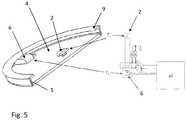
Fig. 1 shows a configuration of a conventional sensor for measuring a core body temperature of a user;Fig. 2 shows another configuration of the conventional sensor;Fig. 3 illustrates yet another configuration of the conventional sensor;Fig. 4 represents a sensor for measuring the core body temperature of a user according to an embodiment;Fig. 5 shows the sensor according to another embodiment;Fig. 6 illustrates a sensor system comprising the sensor according to the embodiments and a control device;Fig. 7 represents the mean square error between the simulated core body temperature and its true value plotted against the thermal conductivity of the insulator resistance for the sensor according to the embodiments; andFig. 8 shows a graph where the core body temperature is plotted against the power of a constant heat source added to the sensor according to the embodiments.Fig. 4 represents asensor 1 according to an embodiment. More particularly,Fig. 4 shows a half cross-section view of thesensor 1 having a circular shape. Thesensor 1 comprises afirst temperature probe 2 to be placed against the surface of theskin 3 of a user for measuring a first temperatureTc. InFig. 4 , thefirst temperature probe 2 is disposed concentric with the symmetry axis A-A of thesensor 1. Athermal insulator 4 embeds thefirst temperature probe 2, forming acontact surface 7 extending in the plane of thefirst temperature probe 2 and destined to be in contact engagement with theskin 3 when thesensor 1 is placed on the user. Thesensor 1 further comprises a thermallyconductive shield 5 covering theouter surface 8 of thethermal insulator 4. In the example ofFig. 4 , theshield 5 comprises a portion, here aflange 9 at its periphery, that covers a portion of thecontact surface 7 and comes also in contact with theskin 3 when thesensor 1 is placed on the user. Other configurations of theconductive shield 5 are possible provided theshield 5 covers at least a portion of the thermal insulatorouter surface 8. Theconductive shield 5 has a thermal conductivity that is much higher compared to the one of thethermal insulator 4 such that the temperature can be considered as substantially equal on the wholeconductive shield 5.- The
sensor 1 further comprises asecond temperature probe 6 for measuring a second temperatureTd. Thesecond temperature probe 6 is disposed at a distance from thefirst temperature probe 2, such as to be thermally insulated from thefirst temperature probe 2 by thethermal insulator 4 and in contact with theconductive shield 5. More particularly, thesecond temperature probe 6 is disposed on the outer surface of theconductive shield 5 such that the measured second temperatureTd corresponds substantially to the temperature of theshield 5. In the example ofFig. 4 , thesecond temperature probe 6 is disposed in contact with the portion, orflange 9, such that is also contacts theskin 3 when thesensor 1 is worn by the user. This placement of thesecond temperature probe 6 minimizes possible inertia due to stabilizing the temperature of theshield 5 compared to, for example, placing thesecond temperature probe 6 on top of the shield, opposed to thefirst temperature probe 2. - Also schematically represented in
Fig. 4 are the underlying regions of theskin 3 and comprising anouter skin region 11 below the skin surface, aninert region 12, and acore body region 13. The heat exchange from the user inner body, orcore body region 13, towards the exterior of theouter skin region 11 is also represented by an equivalent circuit representing a thermal flux model involved in the determination of the core body temperatureTb. More particularly, theouter skin region 11 has a variable perfusion mainly induced by vasoconstriction or vasodilatation of the blood vessels due to adjusting to external temperature variations, and/or varying activity intensity of the user. Theouter skin region 11 can be characterized by an outer thermal resistancer1 and a surface thermal resistancer2, each of the resistancesr1,r2 having a value that increases with decreasing perfusion and decreases with increasing perfusion of theouter skin region 11. Theinert tissue region 12 has a perfusion that is substantially constant and can be characterized by an inert thermal resistanceR of constant value. Fig. 5 represents thesensor 1 according to an exemplary embodiment. More particularly, the left hand side of the figure shows a perspective and across-section view of thesensor 1 having a circular shape, whereas a detail of the temperature probes 2, 6 and a portion of an electronic circuit are shown in the right hand side of the figure. As represented, thefirst temperature probe 2 is placed concentric with theconductive shield 5 andthermal insulator 4, on thecontact surface 7 destined to be in contact with theskin 3. In the present embodiment, thefirst temperature probe 2 is formed by one end of a thermocouple 15 and thesecond temperature probe 6 is formed by its other end. In this configuration, the difference between the first and the second temperaturesTc -Td is measured by using both ends of the thermocouple 15. Instead of measuringTc one can of course measure Td and use the difference to computeTc.- Other arrangements of the first and second temperature probes 2, 6 are possible. For example, the
second temperature probe 6 can be an absolute temperature sensor and thefirst temperature probe 2 can be a thermocouple with its reference at a location that is at a substantially identical temperature as the one measured by thesecond temperature probe 6.. The first and second temperature probes 2, 6 and the thermallyconductive shield 5 can be made of metal, such as stainless steel. Thethermal insulator 4 can be a material having an appropriate thermal conductivity, for example of about 0.03 W/Km, as will be discussed below. Such athermal insulator 4 can be a gel material or air. Air (without convection) has a thermal conductivity of aboutk = 0.026 W/Km between 20°C and 40°C and is a good isolating material for this application. Thethermal insulator 4 can be embedded between a plastic foil, such as a polycarbonate foil, destined to contact theskin 3 and theshield 5. Preferably, thethermal insulator 4 has a thermal conductivity comprised between 0.02 and 0.05 W/Km. Fig. 6 shows asensor system 20 comprising thesensor 1 and a control device controlling the operation of thesensor 1, according to an embodiment. In the example ofFig. 6 , the control device can comprise circuit elements such as a signal conditioning andpre-amplification module 22,AD converters 24,power supply 28, and the chipset needed for recording the data measured by the first and second temperature probes 2, 6, such asconnectors 25, andmemory 27. The circuit elements of the control device can be located on afirst PCB 21 mounted in thesensor 1 or also mounted on asecond PCB 29, as shown inFig. 6 . In this configuration, thethermal insulator 4 can be disposed between the foil and thefirst PCB 21. Thesensor 1 can further comprises amotion sensor 31, mounted in thesecond PCB 29 in the example ofFig. 6 , for measuring motions of the user and determining its level of activity. The motion sensor can be a three-axis accelerometer. Thesensor 1 can also comprise an ambient temperature probe (not shown) for measuring the ambient temperatureTa and possibly other probes (also not shown) for measuring other physiological parameter such as SpO2 and/or heart beat measurements. As shown inFig. 6 , the control device can be controlled by acomputer 32. Since the core body temperatureTb varies relatively slowly, its sampling frequency need not be greater than about 1Hz, a value of 0.2Hz can be appropriate. The signals generated by themotion sensor 31 can be sampled at 20Hz.- In an embodiment, a method for measuring a core body temperature of a user using the
sensor 1 comprises: - providing the
sensor 1 on the user such that thefirst temperature probe 2 and thelower surface 7 contact theskin 3; - measuring the first and second temperatureTc,Td with the first and
second temperature probe - determining the core body temperatureTb from the first and second measured temperaturesTc,Td.
- The core body temperatureTb can be determined form the first and second measured temperaturesTc,Td using the thermal flux model described above and defined by Equation 4:

- In the case where the change in perfusion in the
outer skin region 11 is substantially homogeneous, or the outer and the surface thermal resistancesr1,r2 vary proportionally, the ratior1/r2 can be assumed to be constant. The term comprising the ratios of the resistances inEquation 4 can then be approximated to be constant. Furthermore, if (by an appropriate selection of the thermal conductivityk of the thermal insulator 4) the ratioR/S is set to be equal tor1/r2, the determination of the body temperatureTb becomes independent of the values of the outer thermal and surface resistancesr1,r2, and of the heat exchange resistance A and ambient temperatureTa. In this case,Equation 4 can be rewritten as Equation 5:
Equation 4 being constant. Fig. 7 shows the mean square errorE between the simulated measured core body temperatureTb and a simulated true value, as a function of the thermal conductivityk, or the inverse of the insulator resistanceS (k = 1/S), of thethermal insulator 4. Here, the ambient temperatureTa was defined on a horizontal isotherm located at the distance of 2.4mm from the top of thesensor 1. For each value of the thermal conductivityk, the precision of the estimation of the core body temperatureTb has been computed (quadratic error) usingEquation 5 with the coefficientb (b(k)) minimizing the quadratic error.Fig. 7 shows that the lowest mean square errorE is minimal for the thermal conductivityk equal to about 0.03 W/Km, and thethermal insulator 4 should be selected with its insulator resistanceS around this optimal value. Given this value of the thermal conductivityk,Equation 5 can be rewritten as:
- In yet another embodiment (not represented), the two-dimensional temperatures profiles were simulated in the case where a constant heat source is added above the
thermal insulator 4, or on the face of thePCB 21 opposed to thethermal insulator 4. Such simulations are useful at assessing the influence of thermal dissipation of the electronic components placed on thesensor 1, such as the circuit elements of the control device described above. Here, the constant heat source was modelled as a flat ring, placed concentric with thesensor 1, such as to cover a surface area of about 3 cm2 and producing a constant power over its whole surface. Moreover, the simulations were performed assuming a value of 25°C for the ambient temperatureTa, a thermal conductivity value ofk=0.04 W/Km for thethermal insulator 4, a true core body temperature of 37°C, and a body thermal conductivity forR of 1 W/Km. The value of the constant heat source was varied between 1mW and 1W. - In the graph of
Fig. 8 the determined core body temperatureTb is plotted against the power of the constant heat sourceQ. As shown inFig. 8 , the determined core body temperatureTb decreases proportionally with the power of the constant heat sourceQ and can then be related to the power intensity of the heat source by Equation 7:
sensor 1, and corresponds to 0.68 when the simulations are performed using the above parameters. Consequently, when the heat sourceQ is added to thesensor 1, determining the core body temperature can be performed usingEquation 5 and adding the term -βQ, yielding Equation 8:
Equation 5 being constant (b) has been made. - In an embodiment not represented, the
sensor 1 further comprises a perfusion probe for measuring a perfusion parameter depending on the level of blood perfusion of theskin 3, and more particularly to theouter skin region 11. Here, the perfusion probe can be based on a photopletysmography (ppg) sensor, for example, formed from an emitter comprising a radiation source emitting at the red and/or infrared wavelengths, and a receiver, such as a photodetector, for receiving the optical radiation emitted by the emitter and transmitted through the skin tissue. The radiation source can be an LED, preferably emitting at 660 nm and/or 940 nm. The receiver can be connected to an analog-to-digital converter (ADC) module delivering corresponding measured ppg signal. - According to the invention, transfer functions are used. Such transfer functions allow for correcting the determination of the core body temperatureTb for possible rapid changes in perfusion in the
outer skin region 11 and/or ambient temperatureTa. Thus, in a more generic way,Equation 
conductive shield 5. Here, the transfer functionsF(s) andG(s) are chosen so as to compensate for dynamic change in parameters of the system formed by thesensor 1 and theskin 3, the parameters comprising, for example, external temperature, perfusion and possibly other parameters. - In yet another embodiment not represented, the
sensor 1 is used to measure the local temperature at a measurement point corresponding to the location of thefirst temperature probe 2. - The
sensor 1 according to the embodiments can yield good core body temperature measurement accuracy (theoretically infinite on the described model) since the influence of the ambient temperatureTa and variable perfusion can be compensated. Thesensor 1 is simple and has improved power consumption performance compared to the conventional sensors. Since thesensor 1 is not obtrusive, it provides a better wear comfort for the user. Preferably, thesensor 1 can be worn on locations comprising the upper sternum and the forehead. Such locations are relatively constant in structure for most users, including users suffering from obesity. Table 5 summarizes the advantages of the above sensor with the different advantageous characteristics being rated by one of the numbers comprised between 1 and 4.Table 5 Robustness Comfort Accuracy Safety 3 4 4 4 - 1
- sensor
- 2
- first
- 3
- skin
- 4
- thermal insulator
- 5
- thermally conductive shield
- 6
- second temperature probe
- 7
- contact surface of the thermal insulator
- 8
- outer surface of the thermal insulator
- 9
- flange
- 11
- outer skin region
- 12
- inert tissue region
- 13
- core body region
- 14
- heater device
- 15
- thermocouple
- 20
- sensor system
- 21
- first PCB
- 22
- signal conditioning and pre-amplification module
- 23
- second PCB
- 24
- AD converters
- 25
- connectors
- 26
- transmitter/receiver
- 27
- memory
- 28
- power supply
- 29
- second PCB
- 30
- third PCB
- 31
- motion sensor
- 32
- computer
- A
- heat exchange resistance
- b
- coefficient
- E
- mean square error
- k
- thermal conductivity of the thermal insulator
- Q
- power of the constant heat source
- R
- inert thermal resistance
- r
- outer thermal resistance
- r1
- outer thermal resistance
- r2
- surface thermal resistance
- S
- insulator resistance
- Ta
- ambient temperature
- Tb
- core body temperature
- Tb,Q
- core body temperature with an electronic heat source
- T1,Tc
- first temperature
- T2,Td
- second temperature
- Th
- heater temperature
- ya
- ambient temperature distance


Claims (11)
- A sensor (1) for measuring a core body temperature (Tb) of a user, comprising:a first temperature probe (2) to be placed against the skin (3) of the user for measuring a first temperature (Tc);a second temperature probe (6) at a distance from the first temperature probe (2), for measuring a second temperature (Td) and;a thermal insulator (4) provided between the first and second temperature probes (2, 6) for thermally insulating first and second temperature probes (2, 6) from each other, wherein the thermal insulator (4) embeds the first temperature probe (2), forming a contact surface (7) extending in the plane of the first temperature probe (2) and destined to be in contact engagement with the skin (3);the sensor (1) further comprising a thermally conductive shield (5) covering at least portion of the thermal insulator (4), the second temperature probe (6) being in contact with a portion (9) of the conductive shield (5) arranged to be in contact with the skin (3);characterized in thatthe sensor (1) is configured for determining the core body temperature (Tb) from the first and second measured temperatures (Tc,Td) using Equation (7):

- The sensor (1) according to claim 1, wherein
the second temperature probe (6) is an absolute temperature sensor and
the first temperature probe (2) is a thermocouple with its reference at a location at a substantially identical temperature as the one measured by the second temperature probe (6). - The sensor (1) according to claim 1 or 2,
further comprising a perfusion probe for measuring a perfusion parameter depending on the level of blood perfusion of the skin. - The sensor (1) according to any of the claims from 1 to 3, wherein the sensor (1) is configured for determining the core body temperature (Tb) from the first and second measured temperatures (Tc,Td) using Equation (5):Tb =Tc +b (Tc -Td), wherein b is a constant.
- A sensor system (20) comprising the sensor (1)characterized by any of the claims from 1 to 4 and a control device controlling the operation of the sensor (1).
- The sensor system (20) according to claim 5, wherein
said control device is located on a first PCB (21) mounted in the sensor (1). - A method for measuring a core body temperature (Tb) of a user using the sensor (1)characterized by any of the claims from 1 and 4, comprising:providing the sensor (1) on the user such that the first temperature probe (2) and the contact surface (7) of the thermal insulator (4) contact the skin (3);measuring the first and second temperature (Tc,Td) with the first and second temperature probe (2, 6), respectively; anddetermining the core body temperature (Tb) from the first and second measured temperatures (Tc,Td) using Equation (7):

- The method according to claim 7, wherein determining the core body temperature (Tb) from the first and second measured temperatures (Tc,Td) is performed using Equation (5):Tb =Tc +b (Tc -Td), wherein b is a constant.
- The method according to claim 8,
wherein b is assumed to be 1.54. - The method according to claim 8, wherein
the sensor (1) further comprises a constant heat source above the thermal insulator (4), and wherein said determining the core body temperature (Tb) is performed using Equation (5) to which a term -βQ is added, whereβ being a constant andQ the power of the constant heat source. - The method according to any one of claims 8 to 10, wherein the sensor (1) further comprises a perfusion probe for measuring a perfusion parameter, and wherein the method further comprises a step of measuring the perfusion parameter and using this parameter for determining a value for the constant bin Equation (5).


Applications Claiming Priority (2)
| Application Number | Priority Date | Filing Date | Title |
|---|---|---|---|
| US22879709P | 2009-07-27 | 2009-07-27 | |
| PCT/EP2010/059106WO2011012386A1 (en) | 2009-07-27 | 2010-06-25 | Sensor and method for determining a core body temperature |
Publications (2)
| Publication Number | Publication Date |
|---|---|
| EP2459976A1 EP2459976A1 (en) | 2012-06-06 |
| EP2459976B1true EP2459976B1 (en) | 2018-11-21 |
Family
ID=42937254
Family Applications (1)
| Application Number | Title | Priority Date | Filing Date |
|---|---|---|---|
| EP10730135.0AActiveEP2459976B1 (en) | 2009-07-27 | 2010-06-25 | Sensor and method for determining a core body temperature |
Country Status (3)
| Country | Link |
|---|---|
| EP (1) | EP2459976B1 (en) |
| ES (1) | ES2710276T3 (en) |
| WO (1) | WO2011012386A1 (en) |
Cited By (1)
| Publication number | Priority date | Publication date | Assignee | Title |
|---|---|---|---|---|
| US11766180B1 (en)* | 2020-12-07 | 2023-09-26 | Mark Newton | Identification of a true febrile state in humans through comparison of simultaneously measured core and peripheral temperatures |
Families Citing this family (13)
| Publication number | Priority date | Publication date | Assignee | Title |
|---|---|---|---|---|
| GB2500034A (en)* | 2012-03-07 | 2013-09-11 | Passivsystems Ltd | Calculation of temperature on a remote side of a barrier using thermal conductivity properties of the barrier and temperature measurements |
| JP2016114467A (en)* | 2014-12-15 | 2016-06-23 | ジオマテック株式会社 | Deep body temperature measurement system and deep body temperature measurement method |
| EP3156774B1 (en)* | 2015-10-13 | 2018-04-11 | Koninklijke Philips N.V. | System and method for core body temperature measurement |
| CN108431564B (en) | 2015-12-21 | 2021-04-23 | 皇家飞利浦有限公司 | Heat flow sensor |
| US10750951B1 (en)* | 2016-02-25 | 2020-08-25 | Verily Life Sciences Llc | Core temperature measurement using asymmetric sensors |
| US11406326B2 (en)* | 2017-03-14 | 2022-08-09 | Mordehy HABER | Method, system and device for noninvasive core body temperature monitoring |
| JP6999301B2 (en)* | 2017-06-30 | 2022-01-18 | 株式会社テクノ・コモンズ | Biometric data measuring device |
| JP6999385B2 (en) | 2017-11-30 | 2022-01-18 | 株式会社テクノ・コモンズ | Object data measuring device |
| WO2019133449A1 (en)* | 2017-12-27 | 2019-07-04 | Robert Bosch Gmbh | System and method for determining body core temperature |
| CN111837019B (en) | 2017-12-28 | 2022-09-06 | 科技共享股份有限公司 | Biological data measuring device |
| CN109632144B (en)* | 2019-01-22 | 2023-08-22 | 浙江大学 | A measurement probe for determining the temperature of the biological core |
| EP3699570A1 (en)* | 2019-02-19 | 2020-08-26 | Nederlandse Organisatie voor toegepast- natuurwetenschappelijk onderzoek TNO | Core body temperature sensor and method for the manufacturing thereof |
| CN116337278A (en)* | 2019-03-14 | 2023-06-27 | 生物数据银行股份有限公司 | Temperature sensor unit and in-vivo thermometer |
Family Cites Families (4)
| Publication number | Priority date | Publication date | Assignee | Title |
|---|---|---|---|---|
| EP0399061A1 (en) | 1989-05-22 | 1990-11-28 | Hellige GmbH | Method and device for transcutaneous ZHF temperature measurement |
| US6056435A (en) | 1997-06-24 | 2000-05-02 | Exergen Corporation | Ambient and perfusion normalized temperature detector |
| GB0103886D0 (en) | 2001-02-16 | 2001-04-04 | Baumbach Per L | Temperature measuring device |
| DE102005004933B3 (en) | 2005-02-03 | 2006-08-31 | Dräger Safety AG & Co. KGaA | Device for measuring the body temperature of a living being |
- 2010
- 2010-06-25ESES10730135Tpatent/ES2710276T3/enactiveActive
- 2010-06-25EPEP10730135.0Apatent/EP2459976B1/enactiveActive
- 2010-06-25WOPCT/EP2010/059106patent/WO2011012386A1/enactiveApplication Filing
Non-Patent Citations (1)
| Title |
|---|
| None* |
Cited By (1)
| Publication number | Priority date | Publication date | Assignee | Title |
|---|---|---|---|---|
| US11766180B1 (en)* | 2020-12-07 | 2023-09-26 | Mark Newton | Identification of a true febrile state in humans through comparison of simultaneously measured core and peripheral temperatures |
Also Published As
| Publication number | Publication date |
|---|---|
| EP2459976A1 (en) | 2012-06-06 |
| WO2011012386A1 (en) | 2011-02-03 |
| ES2710276T3 (en) | 2019-04-24 |
Similar Documents
| Publication | Publication Date | Title |
|---|---|---|
| EP2459976B1 (en) | Sensor and method for determining a core body temperature | |
| Childs | Body temperature and clinical thermometry | |
| Tamura et al. | Current developments in wearable thermometers | |
| US10827931B2 (en) | Patch for temperature determination | |
| AU2018223205B2 (en) | Temperature sensor | |
| Anbar et al. | Thermology and facial telethermography. Part I: history and technical review | |
| van Marken Lichtenbelt et al. | Evaluation of wireless determination of skin temperature using iButtons | |
| US7787938B2 (en) | Temporal artery temperature detector | |
| US5924996A (en) | Process and device for detecting the exchange of heat between the human body and the invented device and its correlation to the glucose concentration in human blood | |
| US5795305A (en) | Process and device for non-invasive determination of glucose concentration in parts of the human body | |
| US9410854B2 (en) | Methods and devices for measuring core body temperature | |
| CA2583034C (en) | Bandage with sensors | |
| US20120029369A1 (en) | Passive Microwave Assessment of Human Body Core to Surface Temperature Gradients and Basal Metabolic Rate | |
| JP2019097819A (en) | Biological data measuring apparatus | |
| US8013745B2 (en) | Passive microwave assessment of human body core to surface temperature gradients and basal metabolic rate | |
| US20220128413A1 (en) | Core body temperature sensor and method for the manufacturing thereof | |
| US20220000370A1 (en) | Core body temperature sensor system based on flux measurement | |
| JP2005027821A (en) | Blood glucose level measuring device | |
| Huang et al. | Wearable deep body thermometers and their uses in continuous monitoring for daily healthcare | |
| WO2009152418A1 (en) | Passive microwave assessment of human body core to surface temperature gradients and basal metabolic rate | |
| Tamura et al. | Body temperature, heat flow, and evaporation | |
| Ren et al. | A novel miniaturized sandwich-like sensor for continuous measurement of core body temperature | |
| Finvers et al. | Wireless temporal artery bandage thermometer | |
| CA2727435A1 (en) | Passive microwave assessment of human body core to surface temperature gradients and basal metabolic rate | |
| Kyriacou et al. | Temperature sensor technology |
Legal Events
| Date | Code | Title | Description |
|---|---|---|---|
| PUAI | Public reference made under article 153(3) epc to a published international application that has entered the european phase | Free format text:ORIGINAL CODE: 0009012 | |
| 17P | Request for examination filed | Effective date:20111209 | |
| AK | Designated contracting states | Kind code of ref document:A1 Designated state(s):AL AT BE BG CH CY CZ DE DK EE ES FI FR GB GR HR HU IE IS IT LI LT LU LV MC MK MT NL NO PL PT RO SE SI SK SM TR | |
| DAX | Request for extension of the european patent (deleted) | ||
| RIN1 | Information on inventor provided before grant (corrected) | Inventor name:CHETELAT, OLIVIER Inventor name:BERTCHI, MATTIA Inventor name:NEUMAN, VICTOR | |
| 17Q | First examination report despatched | Effective date:20160429 | |
| STAA | Information on the status of an ep patent application or granted ep patent | Free format text:STATUS: EXAMINATION IS IN PROGRESS | |
| GRAP | Despatch of communication of intention to grant a patent | Free format text:ORIGINAL CODE: EPIDOSNIGR1 | |
| STAA | Information on the status of an ep patent application or granted ep patent | Free format text:STATUS: GRANT OF PATENT IS INTENDED | |
| INTG | Intention to grant announced | Effective date:20180621 | |
| GRAS | Grant fee paid | Free format text:ORIGINAL CODE: EPIDOSNIGR3 | |
| GRAA | (expected) grant | Free format text:ORIGINAL CODE: 0009210 | |
| STAA | Information on the status of an ep patent application or granted ep patent | Free format text:STATUS: THE PATENT HAS BEEN GRANTED | |
| AK | Designated contracting states | Kind code of ref document:B1 Designated state(s):AL AT BE BG CH CY CZ DE DK EE ES FI FR GB GR HR HU IE IS IT LI LT LU LV MC MK MT NL NO PL PT RO SE SI SK SM TR | |
| RAP1 | Party data changed (applicant data changed or rights of an application transferred) | Owner name:CSEM CENTRE SUISSE D'ELECTRONIQUE ET DE MICROTECHN | |
| REG | Reference to a national code | Ref country code:CH Ref legal event code:EP | |
| REG | Reference to a national code | Ref country code:IE Ref legal event code:FG4D | |
| REG | Reference to a national code | Ref country code:DE Ref legal event code:R096 Ref document number:602010055255 Country of ref document:DE | |
| REG | Reference to a national code | Ref country code:AT Ref legal event code:REF Ref document number:1068093 Country of ref document:AT Kind code of ref document:T Effective date:20181215 | |
| REG | Reference to a national code | Ref country code:CH Ref legal event code:NV Representative=s name:NOVAGRAAF INTERNATIONAL SA, CH | |
| REG | Reference to a national code | Ref country code:NL Ref legal event code:MP Effective date:20181121 | |
| REG | Reference to a national code | Ref country code:AT Ref legal event code:MK05 Ref document number:1068093 Country of ref document:AT Kind code of ref document:T Effective date:20181121 | |
| REG | Reference to a national code | Ref country code:ES Ref legal event code:FG2A Ref document number:2710276 Country of ref document:ES Kind code of ref document:T3 Effective date:20190424 | |
| PG25 | Lapsed in a contracting state [announced via postgrant information from national office to epo] | Ref country code:FI Free format text:LAPSE BECAUSE OF FAILURE TO SUBMIT A TRANSLATION OF THE DESCRIPTION OR TO PAY THE FEE WITHIN THE PRESCRIBED TIME-LIMIT Effective date:20181121 Ref country code:LV Free format text:LAPSE BECAUSE OF FAILURE TO SUBMIT A TRANSLATION OF THE DESCRIPTION OR TO PAY THE FEE WITHIN THE PRESCRIBED TIME-LIMIT Effective date:20181121 Ref country code:HR Free format text:LAPSE BECAUSE OF FAILURE TO SUBMIT A TRANSLATION OF THE DESCRIPTION OR TO PAY THE FEE WITHIN THE PRESCRIBED TIME-LIMIT Effective date:20181121 Ref country code:LT Free format text:LAPSE BECAUSE OF FAILURE TO SUBMIT A TRANSLATION OF THE DESCRIPTION OR TO PAY THE FEE WITHIN THE PRESCRIBED TIME-LIMIT Effective date:20181121 Ref country code:AT Free format text:LAPSE BECAUSE OF FAILURE TO SUBMIT A TRANSLATION OF THE DESCRIPTION OR TO PAY THE FEE WITHIN THE PRESCRIBED TIME-LIMIT Effective date:20181121 Ref country code:BG Free format text:LAPSE BECAUSE OF FAILURE TO SUBMIT A TRANSLATION OF THE DESCRIPTION OR TO PAY THE FEE WITHIN THE PRESCRIBED TIME-LIMIT Effective date:20190221 Ref country code:IS Free format text:LAPSE BECAUSE OF FAILURE TO SUBMIT A TRANSLATION OF THE DESCRIPTION OR TO PAY THE FEE WITHIN THE PRESCRIBED TIME-LIMIT Effective date:20190321 Ref country code:NO Free format text:LAPSE BECAUSE OF FAILURE TO SUBMIT A TRANSLATION OF THE DESCRIPTION OR TO PAY THE FEE WITHIN THE PRESCRIBED TIME-LIMIT Effective date:20190221 | |
| PG25 | Lapsed in a contracting state [announced via postgrant information from national office to epo] | Ref country code:NL Free format text:LAPSE BECAUSE OF FAILURE TO SUBMIT A TRANSLATION OF THE DESCRIPTION OR TO PAY THE FEE WITHIN THE PRESCRIBED TIME-LIMIT Effective date:20181121 Ref country code:GR Free format text:LAPSE BECAUSE OF FAILURE TO SUBMIT A TRANSLATION OF THE DESCRIPTION OR TO PAY THE FEE WITHIN THE PRESCRIBED TIME-LIMIT Effective date:20190222 Ref country code:PT Free format text:LAPSE BECAUSE OF FAILURE TO SUBMIT A TRANSLATION OF THE DESCRIPTION OR TO PAY THE FEE WITHIN THE PRESCRIBED TIME-LIMIT Effective date:20190321 Ref country code:SE Free format text:LAPSE BECAUSE OF FAILURE TO SUBMIT A TRANSLATION OF THE DESCRIPTION OR TO PAY THE FEE WITHIN THE PRESCRIBED TIME-LIMIT Effective date:20181121 Ref country code:AL Free format text:LAPSE BECAUSE OF FAILURE TO SUBMIT A TRANSLATION OF THE DESCRIPTION OR TO PAY THE FEE WITHIN THE PRESCRIBED TIME-LIMIT Effective date:20181121 | |
| PG25 | Lapsed in a contracting state [announced via postgrant information from national office to epo] | Ref country code:CZ Free format text:LAPSE BECAUSE OF FAILURE TO SUBMIT A TRANSLATION OF THE DESCRIPTION OR TO PAY THE FEE WITHIN THE PRESCRIBED TIME-LIMIT Effective date:20181121 Ref country code:PL Free format text:LAPSE BECAUSE OF FAILURE TO SUBMIT A TRANSLATION OF THE DESCRIPTION OR TO PAY THE FEE WITHIN THE PRESCRIBED TIME-LIMIT Effective date:20181121 Ref country code:DK Free format text:LAPSE BECAUSE OF FAILURE TO SUBMIT A TRANSLATION OF THE DESCRIPTION OR TO PAY THE FEE WITHIN THE PRESCRIBED TIME-LIMIT Effective date:20181121 | |
| PGFP | Annual fee paid to national office [announced via postgrant information from national office to epo] | Ref country code:IT Payment date:20190626 Year of fee payment:10 | |
| REG | Reference to a national code | Ref country code:DE Ref legal event code:R097 Ref document number:602010055255 Country of ref document:DE | |
| PG25 | Lapsed in a contracting state [announced via postgrant information from national office to epo] | Ref country code:SM Free format text:LAPSE BECAUSE OF FAILURE TO SUBMIT A TRANSLATION OF THE DESCRIPTION OR TO PAY THE FEE WITHIN THE PRESCRIBED TIME-LIMIT Effective date:20181121 Ref country code:EE Free format text:LAPSE BECAUSE OF FAILURE TO SUBMIT A TRANSLATION OF THE DESCRIPTION OR TO PAY THE FEE WITHIN THE PRESCRIBED TIME-LIMIT Effective date:20181121 Ref country code:SK Free format text:LAPSE BECAUSE OF FAILURE TO SUBMIT A TRANSLATION OF THE DESCRIPTION OR TO PAY THE FEE WITHIN THE PRESCRIBED TIME-LIMIT Effective date:20181121 Ref country code:RO Free format text:LAPSE BECAUSE OF FAILURE TO SUBMIT A TRANSLATION OF THE DESCRIPTION OR TO PAY THE FEE WITHIN THE PRESCRIBED TIME-LIMIT Effective date:20181121 | |
| PLBE | No opposition filed within time limit | Free format text:ORIGINAL CODE: 0009261 | |
| STAA | Information on the status of an ep patent application or granted ep patent | Free format text:STATUS: NO OPPOSITION FILED WITHIN TIME LIMIT | |
| 26N | No opposition filed | Effective date:20190822 | |
| PG25 | Lapsed in a contracting state [announced via postgrant information from national office to epo] | Ref country code:SI Free format text:LAPSE BECAUSE OF FAILURE TO SUBMIT A TRANSLATION OF THE DESCRIPTION OR TO PAY THE FEE WITHIN THE PRESCRIBED TIME-LIMIT Effective date:20181121 | |
| PGFP | Annual fee paid to national office [announced via postgrant information from national office to epo] | Ref country code:DK Payment date:20190910 Year of fee payment:17 | |
| PG25 | Lapsed in a contracting state [announced via postgrant information from national office to epo] | Ref country code:MC Free format text:LAPSE BECAUSE OF FAILURE TO SUBMIT A TRANSLATION OF THE DESCRIPTION OR TO PAY THE FEE WITHIN THE PRESCRIBED TIME-LIMIT Effective date:20181121 | |
| REG | Reference to a national code | Ref country code:BE Ref legal event code:MM Effective date:20190630 | |
| PG25 | Lapsed in a contracting state [announced via postgrant information from national office to epo] | Ref country code:TR Free format text:LAPSE BECAUSE OF FAILURE TO SUBMIT A TRANSLATION OF THE DESCRIPTION OR TO PAY THE FEE WITHIN THE PRESCRIBED TIME-LIMIT Effective date:20181121 | |
| PG25 | Lapsed in a contracting state [announced via postgrant information from national office to epo] | Ref country code:IE Free format text:LAPSE BECAUSE OF NON-PAYMENT OF DUE FEES Effective date:20190625 | |
| PG25 | Lapsed in a contracting state [announced via postgrant information from national office to epo] | Ref country code:BE Free format text:LAPSE BECAUSE OF NON-PAYMENT OF DUE FEES Effective date:20190630 Ref country code:LU Free format text:LAPSE BECAUSE OF NON-PAYMENT OF DUE FEES Effective date:20190625 | |
| PG25 | Lapsed in a contracting state [announced via postgrant information from national office to epo] | Ref country code:CY Free format text:LAPSE BECAUSE OF FAILURE TO SUBMIT A TRANSLATION OF THE DESCRIPTION OR TO PAY THE FEE WITHIN THE PRESCRIBED TIME-LIMIT Effective date:20181121 | |
| PG25 | Lapsed in a contracting state [announced via postgrant information from national office to epo] | Ref country code:MT Free format text:LAPSE BECAUSE OF FAILURE TO SUBMIT A TRANSLATION OF THE DESCRIPTION OR TO PAY THE FEE WITHIN THE PRESCRIBED TIME-LIMIT Effective date:20181121 Ref country code:HU Free format text:LAPSE BECAUSE OF FAILURE TO SUBMIT A TRANSLATION OF THE DESCRIPTION OR TO PAY THE FEE WITHIN THE PRESCRIBED TIME-LIMIT; INVALID AB INITIO Effective date:20100625 | |
| PG25 | Lapsed in a contracting state [announced via postgrant information from national office to epo] | Ref country code:IT Free format text:LAPSE BECAUSE OF NON-PAYMENT OF DUE FEES Effective date:20200625 | |
| PG25 | Lapsed in a contracting state [announced via postgrant information from national office to epo] | Ref country code:ES Free format text:LAPSE BECAUSE OF NON-PAYMENT OF DUE FEES Effective date:20200626 | |
| PG25 | Lapsed in a contracting state [announced via postgrant information from national office to epo] | Ref country code:MK Free format text:LAPSE BECAUSE OF FAILURE TO SUBMIT A TRANSLATION OF THE DESCRIPTION OR TO PAY THE FEE WITHIN THE PRESCRIBED TIME-LIMIT Effective date:20181121 | |
| PGFP | Annual fee paid to national office [announced via postgrant information from national office to epo] | Ref country code:CH Payment date:20240701 Year of fee payment:15 | |
| PGFP | Annual fee paid to national office [announced via postgrant information from national office to epo] | Ref country code:DE Payment date:20250618 Year of fee payment:16 | |
| PGFP | Annual fee paid to national office [announced via postgrant information from national office to epo] | Ref country code:GB Payment date:20250620 Year of fee payment:16 | |
| PGFP | Annual fee paid to national office [announced via postgrant information from national office to epo] | Ref country code:FR Payment date:20250618 Year of fee payment:16 |