EP2457467B1 - Chair structure and method of assembling the same - Google Patents
Chair structure and method of assembling the sameDownload PDFInfo
- Publication number
- EP2457467B1 EP2457467B1EP10192708.5AEP10192708AEP2457467B1EP 2457467 B1EP2457467 B1EP 2457467B1EP 10192708 AEP10192708 AEP 10192708AEP 2457467 B1EP2457467 B1EP 2457467B1
- Authority
- EP
- European Patent Office
- Prior art keywords
- coupling element
- chair structure
- seat frame
- support base
- structure according
- Prior art date
- Legal status (The legal status is an assumption and is not a legal conclusion. Google has not performed a legal analysis and makes no representation as to the accuracy of the status listed.)
- Active
Links
Images


Classifications
- A—HUMAN NECESSITIES
- A47—FURNITURE; DOMESTIC ARTICLES OR APPLIANCES; COFFEE MILLS; SPICE MILLS; SUCTION CLEANERS IN GENERAL
- A47C—CHAIRS; SOFAS; BEDS
- A47C3/00—Chairs characterised by structural features; Chairs or stools with rotatable or vertically-adjustable seats
- A47C3/18—Chairs or stools with rotatable seat
- A—HUMAN NECESSITIES
- A47—FURNITURE; DOMESTIC ARTICLES OR APPLIANCES; COFFEE MILLS; SPICE MILLS; SUCTION CLEANERS IN GENERAL
- A47C—CHAIRS; SOFAS; BEDS
- A47C4/00—Foldable, collapsible or dismountable chairs
- A47C4/02—Dismountable chairs
- A—HUMAN NECESSITIES
- A47—FURNITURE; DOMESTIC ARTICLES OR APPLIANCES; COFFEE MILLS; SPICE MILLS; SUCTION CLEANERS IN GENERAL
- A47C—CHAIRS; SOFAS; BEDS
- A47C7/00—Parts, details, or accessories of chairs or stools
- A47C7/002—Chair or stool bases
Definitions
- the present inventionrelates to chair structures and methods of assembling chair structures.
- a conventional chair structureusually includes a seat portion that is assembled on a support structure.
- certain chair structuresmay also include a pivoting mechanism that allows rotation of the seating portion relative to the support structure, such that a user can push the seat portion in rotation while remaining seated on the seat portion.
- the pivoting mechanism usually employed in the convention chairdoes not permit disassembly of the chair structure. As a result, when the chair is not used, the chair cannot be stored in a compact form.
- the present applicationdescribes a system and method for assembling the chair structure.
- the chair structurecomprises a seat frame having a first coupling element, a support base, and a pivot link assembly mounted on the support base.
- the pivot link assemblyincludes a pivot axle, and a second coupling element pivotally mounted around the pivot axle, wherein the second coupling element includes a latch operable to lock the first coupling element with the second coupling element when the seat frame is assembled with the support base, and unlock the first coupling element from the second coupling element for allowing separation of the seat frame from the support base.
- the present applicationalso describes a method for assembling the chair structure.
- the methodcomprises providing a seat frame having a first coupling element having a hole, providing a support base having a pivot axle and a second coupling element pivotally mounted around the pivot axle, wherein the second coupling element includes a latch thereon, and assembling the seat frame with the support base by sliding the first coupling element over the second coupling element until the latch engages through the hole for locking the first coupling element with the second coupling element.
- At least one advantage of the chair structure and method described hereinis the ability of the seat frame to assemble with and separate from the support base in a convenient manner. Storage of the chair structure can be thereby facilitated.
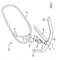
- FIG. 1is an exploded view illustrating a seat frame and support base of a chair structure according to one embodiment of the present invention
- FIG. 2is a perspective view of a chair structure according to one embodiment of the present invention.
- FIG. 3is a schematic cross-sectional view illustrating a pivot link assembly implemented in a chair structure according to an embodiment of the present invention
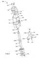
- FIG. 4is an exploded view of the pivot link assembly shown in FIG. 3 ;
- FIG. 5is a perspective of the pivot link assembly shown in FIG. 4
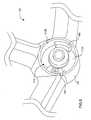
- FIG. 6is a schematic enlarged view of the support base shown in FIG. 1 ;
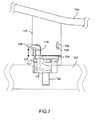
- FIG. 7is a schematic view illustrating an operation of the chair structure of FIG. 1 .
- the present applicationdescribes a chair structure and a method for assembling the chair structure.
- Examples of use of the chair structure described hereinmay include, without limitation, a chair for seating a young infant or baby.
- FIGs. 1 and 2are respectively exploded and perspective views illustrating one embodiment of a chair structure 100.
- the chair structure 100comprises a support base 102, a seat frame 104, and a pivot link assembly 106 mounted on the support base 102.
- the support base 102may include a plurality of resting beams 108 that extend radial from a joint portion 110 for providing stable support of the chair structure 100 on a floor.
- the joint portion 110 of the support base 102has an inner cavity 112 in which the pivot link assembly 106 is fixedly mounted.
- the seat frame 104may include a tubular structure 114 having a bracket 115 and a first coupling element 117 affixed on the bracket 115.
- the first coupling element 117may be formed as an enclosing cup having a hollow inner volume in which the pivot link assembly 106 can be received when the seat frame 104 is assembled on the support base 102.
- a side of the first coupling element 117can include a slot 119 that is able to engage with a second coupling element 124 (e.g., shown in FIG. 3 ) provided on the pivot link assembly 106 for enabling rotation of the seat frame 104 relative to the support base 102 about a rotation axis Y defined by the pivot link assembly 106.
- FIGs. 3-5are respectively cross-sectional, exploded and perspective views illustrating the construction of the pivot link assembly 106 and how it assembles with the support base 102 and first coupling element 117.
- the first coupling element 117may include an outer enclosing cup 117A in which is mounted an inner cup 117B having a hollow inner volume.
- the pivot link assembly 106includes a pivot axle 122 that defines the rotation axis Y, and a second coupling element 124 pivotally mounted around the pivot axle 122.
- the pivot axle 122has a first end 122A affixed in the inner cavity 112 of the support base 102.
- the inner cavity 112is at least partially delimited by a bottom surface 112A and sidewall 112B.
- a hole 123is formed through the bottom surface 112A and is downwardly closed by an end cap 125.
- the first end 122A of the pivot axle 122 having a threaded hole 126is assembled through the hole 123 and fixedly secured with the end cap 125 via a screw 128 that engages through the end cap 125 with the threaded hole 126.
- the second coupling element 124includes a sleeve 130, a cover 132 and an anti-rotation lock 134.
- the sleeve 130has a hollow, generally elongated shape that has an inner bore 136 through which the pivot axle 122 is pivotally mounted via bearings 137A and 137B.
- the bearing 137Amay be mounted adjacent to a top end 130A of the sleeve 130 and tightly fitted around a second end 122B of the pivot axle 122 opposite its first end 122A.
- the bearing 137Bis tightly mounted around the pivot axle 122 in abutment against a shoulder portion 122C of the pivot axle 122, at an intermediate position between the first end 122A and second end 122B of the pivot axle 122.
- the inner bore 136may be downwardly closed by a seal 138, which is fastened via a collar 139 against the bearing 137B at a side opposite the shoulder portion 122C.
- the seal 138can prevent dust contamination through the lower end of the inner bore 136.
- the top end 130A of the sleeve 130is closed with the cover 132 fixedly secured via screws 135.
- a side 130B of the sleeve 130forms a recessed, elongated pocket 140 through which the anti-rotation lock 134 is assembled in sliding relationship along the direction of the rotation axis Y.
- the anti-rotation lock 134may be formed as an elongated member slidably mounted through the pocket 140.
- a first end 134A of the anti-rotation lock 134includes two restricting flanges 142 (better shown in FIG. 4 ) that are spaced apart from each other and delimit a gap 144 there between.
- a second end 134B of the anti-rotation lock 134 opposite its first end 134Aincludes a catch 146 that is able to detachably fasten with a rib 147 protruding inward from an inner sidewall of the sleeve 130 (better shown in FIG. 3 ).
- an intermediate portion of the anti-rotation lock 134 between the first end 134A and the second end 134Bincludes a handle 148 that extends radial from the direction of the rotation axis Y for engaging through the slot 119 of the first coupling element 117 (shown in FIG. 1 ). By pulling the handle 148 downward or upward, the anti-rotation lock 134 can slide vertically to either a first position or second position higher than the first position.
- the restricting flanges 142 of the anti-rotation lock 134can be placed adjacent to two lateral sides of a protuberance 162 formed in the inner cavity 112 (better shown in FIG. 6 ) for blocking rotation of the seat frame 104 about the pivot axle 122.
- the restricting flanges 142are positioned in a gap above the protuberance 162 such that rotation of the seat frame 104 about the pivot axle 122 is allowed.
- the second coupling element 124also includes a latch 150 that is provided on an outer side of the second coupling element 124.
- the latch 150may include a tab portion 152 extending downward from the cover 132, and a flange 154 protruding outward from the tab portion 152 and extending radial from the direction of the rotation axis Y.
- the flange 154can engage through or disengage from a hole 156 provided through the first coupling element 117 (better shown in FIG. 7 ).
- the flange 154can abut against a rim portion of the hole 156 for locking the first coupling element 117 with the second coupling element 124.
- a lower portion 130C of the sleeve 130 opposite the top end 130Aincludes two opposite abuttal flanges 158 (only one abuttal flange 158 is visible on FIG. 5 ) that are spaced-apart from each other and laid in different radial directions.
- abuttal flanges 158When the seat frame 104 assembled on the support base 102 is rotated, either of the two abuttal flanges 158 can come in abutment against a stop element provided in the inner cavity 112 (better shown in FIG. 6 ) so as to delimit a maximum angle of rotation permitted for the seat frame 104.
- FIG. 6is a schematic enlarged view illustrating the inner cavity 112 of the support base 102.
- the sidewall 112B surrounding the inner cavity 112may have a generally cylindrical contour.
- the protuberance 162 against which the anti-rotation lock 134 abuts for blocking rotation of the seat frame 104protrudes upward from the bottom surface 112A of the inner cavity 112.
- a cushion pad 164is also fixed on the bottom surface 112A at a position diametrically opposite the protuberance 162.
- the cushion pad 164is placed in an area located between the two abuttal flanges 158.
- the limits of the angular rotation permitted for the seat frame 104are reached when either of the two abuttal flanges 158 comes in abutment against the cushion pad 164.
- the cushion pad 164may be made of a flexible material adapted to cushion collision of the abuttal flanges 158 against the cushion pad 164 for stopping rotation of the seat frame 104.
- a variant embodimentcan also configure the cushion pad 164 as a spring element (e.g., the cushion pad 164 may be made of a resilient material) that is loaded and provides a resilient force when it is pressed by the abuttal flange 158.
- the cushion pad 164can deform and apply a counteracting force that causes the seat frame 104 to rotate in a reverse direction.
- the seat frame 104can then rotate reversely until the opposite abuttal flange 158 comes in contact with an opposite second side of the cushion pad 164, which applies again a counteracting force to rotate the seat frame 104 toward the first side of the cushion pad 164. Accordingly, the seat frame 104 can bounce against the cushion pad 164 to perform reciprocated rotational movements, thereby providing an entertaining environment to the seated child.
- the seat frame 104can be assembled on the support base 102 by sliding the first coupling element 117 over the second coupling element 124 of the pivot link assembly 106. As shown in FIG. 7 , the connection between the first coupling element 117 and the second coupling element 124 is then locked when the latch 150 engages through the hole 156 of the first coupling element 117. Moreover, the first coupling element 117 and the second coupling element 124 are also coupled with each other respectively via the engagement of the handle 148 through the slot 119 of the first coupling element 117, and the engagement between the slot 119 of the first coupling element 117 and outline protrusions of the elongated pocket 140.
- the anti-rotation lock 134can be raised until the catch 146 of the anti-rotation lock 134 engages and grips the rib 147 of the sleeve 130 by resilient deflection.
- the anti-rotation lock 134can thereby be securely maintained at a higher position (i.e., the second position previously mentioned and shown with solid lines in FIG. 7 ) where the restricting flanges 142 are positioned in a gap above the protuberance 162.
- the seat frame 104can then be rotated relative to the support base 102, which results in a unitary rotating movement of the first and second coupling elements 117 and 124 locked with each other around the pivot axle 122.
- the rotation movement of the seat frame 104 relative to the support base 102can be transmitted from the first coupling element 117 to the second coupling element 124 through contact between the handle 148 and an edge of the slot 119 of the first coupling element 117.
- the seat frame 104first must be oriented to a position where the handle 148 is in alignment with the protuberance 162.
- the catch 146can disengage from the rib 147, and the anti-rotation lock 134 can then slide downward to a lower position (i.e., the first position previously mentioned and shown with phantom lines in FIG. 7 ) where the protuberance 162 is lodged in the gap 144 between the two restricting flanges 142.
- the restricting flanges 142are placed adjacently against two opposite lateral sides of the protuberance 162.
- any rotation of the second coupling element 124 (and the first coupling element 117 and seat frame 104 locked therewith) about the rotation axis Ycan be blocked owing to abutment between the protuberance 162 and of either of the restricting flanges 142.
- the usercan disassemble the chair structure 100 by pushing the latch 150, in particular the protruding flange 154, to cause inward deflection of the tab portion 152.
- the flange 154can disengage from the hole 156, and the latch 150 thereby unlocks the connection between the first and second coupling elements 117 and 124.
- the seat frame 104 and the first coupling element 117 fixed thereoncan then be pulled upward away from the support base 102 and the pivot link assembly 106.
- the seat frame 104can then be stored separately from the support base 102.
- At least one advantage of the chair structure described hereinis the ability of the seat frame to assemble on and separate from the support base in a convenient manner. Such feature may be particularly advantageous when the seat frame can also folded into a compact form, allowing convenient storage of the chair structure in a reduced space. In addition, when the seat frame is assembled with the support base, rotation of the seat frame can also be selectively enabled or blocked for providing safer use of the chair structure.
Landscapes
- Chairs For Special Purposes, Such As Reclining Chairs (AREA)
- Chairs Characterized By Structure (AREA)
Description
- 1. Field of the Invention
- The present invention relates to chair structures and methods of assembling chair structures.
- 2. Description of the Related Art
- A conventional chair structure, exemplarily shown in patent applicaton
EP 2 127 560 A1 , usually includes a seat portion that is assembled on a support structure. To allow convenient use, certain chair structures may also include a pivoting mechanism that allows rotation of the seating portion relative to the support structure, such that a user can push the seat portion in rotation while remaining seated on the seat portion. However, the pivoting mechanism usually employed in the convention chair does not permit disassembly of the chair structure. As a result, when the chair is not used, the chair cannot be stored in a compact form. - Therefore, there is presently a need for a chair structure that can be easily assembled and disassembled, and address at least the foregoing issues.
- The present application describes a system and method for assembling the chair structure.
- According to one embodiment, the chair structure comprises a seat frame having a first coupling element, a support base, and a pivot link assembly mounted on the support base. The pivot link assembly includes a pivot axle, and a second coupling element pivotally mounted around the pivot axle, wherein the second coupling element includes a latch operable to lock the first coupling element with the second coupling element when the seat frame is assembled with the support base, and unlock the first coupling element from the second coupling element for allowing separation of the seat frame from the support base.
- The present application also describes a method for assembling the chair structure. In one embodiment, the method comprises providing a seat frame having a first coupling element having a hole, providing a support base having a pivot axle and a second coupling element pivotally mounted around the pivot axle, wherein the second coupling element includes a latch thereon, and assembling the seat frame with the support base by sliding the first coupling element over the second coupling element until the latch engages through the hole for locking the first coupling element with the second coupling element.
- At least one advantage of the chair structure and method described herein is the ability of the seat frame to assemble with and separate from the support base in a convenient manner. Storage of the chair structure can be thereby facilitated.
- The foregoing is a summary and shall not be construed to limit the scope of the claims. The operations and structures disclosed herein may be implemented in a number of ways, and such changes and modifications may be made without departing from this invention and its broader aspects. Other aspects, inventive features, and advantages of the invention, as defined solely by the claims, are described in the nonlimiting detailed description set forth below.
FIG. 1 is an exploded view illustrating a seat frame and support base of a chair structure according to one embodiment of the present invention;FIG. 2 is a perspective view of a chair structure according to one embodiment of the present invention;FIG. 3 is a schematic cross-sectional view illustrating a pivot link assembly implemented in a chair structure according to an embodiment of the present invention;FIG. 4 is an exploded view of the pivot link assembly shown inFIG. 3 ;FIG. 5 is a perspective of the pivot link assembly shown inFIG. 4 FIG. 6 is a schematic enlarged view of the support base shown inFIG. 1 ; andFIG. 7 is a schematic view illustrating an operation of the chair structure ofFIG. 1 .- The present application describes a chair structure and a method for assembling the chair structure. Examples of use of the chair structure described herein may include, without limitation, a chair for seating a young infant or baby.
FIGs. 1 and2 are respectively exploded and perspective views illustrating one embodiment of achair structure 100. Thechair structure 100 comprises asupport base 102, aseat frame 104, and apivot link assembly 106 mounted on thesupport base 102. Thesupport base 102 may include a plurality ofresting beams 108 that extend radial from ajoint portion 110 for providing stable support of thechair structure 100 on a floor. Thejoint portion 110 of thesupport base 102 has aninner cavity 112 in which thepivot link assembly 106 is fixedly mounted. Theseat frame 104 may include atubular structure 114 having abracket 115 and afirst coupling element 117 affixed on thebracket 115. In one embodiment, thefirst coupling element 117 may be formed as an enclosing cup having a hollow inner volume in which thepivot link assembly 106 can be received when theseat frame 104 is assembled on thesupport base 102. In particular, a side of thefirst coupling element 117 can include aslot 119 that is able to engage with a second coupling element 124 (e.g., shown inFIG. 3 ) provided on thepivot link assembly 106 for enabling rotation of theseat frame 104 relative to thesupport base 102 about a rotation axis Y defined by thepivot link assembly 106.FIGs. 3-5 are respectively cross-sectional, exploded and perspective views illustrating the construction of thepivot link assembly 106 and how it assembles with thesupport base 102 andfirst coupling element 117. As shown inFIG. 3 , thefirst coupling element 117 may include an outer enclosingcup 117A in which is mounted aninner cup 117B having a hollow inner volume. Further, referring toFIGs. 3 and4 , thepivot link assembly 106 includes apivot axle 122 that defines the rotation axis Y, and asecond coupling element 124 pivotally mounted around thepivot axle 122. Thepivot axle 122 has afirst end 122A affixed in theinner cavity 112 of thesupport base 102. More particularly, theinner cavity 112 is at least partially delimited by abottom surface 112A andsidewall 112B. Ahole 123 is formed through thebottom surface 112A and is downwardly closed by anend cap 125. Thefirst end 122A of thepivot axle 122 having a threadedhole 126 is assembled through thehole 123 and fixedly secured with theend cap 125 via ascrew 128 that engages through theend cap 125 with the threadedhole 126.- The
second coupling element 124 includes asleeve 130, acover 132 and ananti-rotation lock 134. Thesleeve 130 has a hollow, generally elongated shape that has aninner bore 136 through which thepivot axle 122 is pivotally mounted viabearings bearing 137A may be mounted adjacent to atop end 130A of thesleeve 130 and tightly fitted around asecond end 122B of thepivot axle 122 opposite itsfirst end 122A. Thebearing 137B is tightly mounted around thepivot axle 122 in abutment against ashoulder portion 122C of thepivot axle 122, at an intermediate position between thefirst end 122A andsecond end 122B of thepivot axle 122. Theinner bore 136 may be downwardly closed by aseal 138, which is fastened via acollar 139 against thebearing 137B at a side opposite theshoulder portion 122C. Theseal 138 can prevent dust contamination through the lower end of theinner bore 136. Thetop end 130A of thesleeve 130 is closed with thecover 132 fixedly secured viascrews 135. - As shown in
FIGs. 3-5 , aside 130B of thesleeve 130 forms a recessed,elongated pocket 140 through which theanti-rotation lock 134 is assembled in sliding relationship along the direction of the rotation axis Y. In one embodiment, theanti-rotation lock 134 may be formed as an elongated member slidably mounted through thepocket 140. Afirst end 134A of theanti-rotation lock 134 includes two restricting flanges 142 (better shown inFIG. 4 ) that are spaced apart from each other and delimit agap 144 there between. Asecond end 134B of theanti-rotation lock 134 opposite itsfirst end 134A includes acatch 146 that is able to detachably fasten with arib 147 protruding inward from an inner sidewall of the sleeve 130 (better shown inFIG. 3 ).
In addition, an intermediate portion of theanti-rotation lock 134 between thefirst end 134A and thesecond end 134B includes ahandle 148 that extends radial from the direction of the rotation axis Y for engaging through theslot 119 of the first coupling element 117 (shown inFIG. 1 ). By pulling thehandle 148 downward or upward, theanti-rotation lock 134 can slide vertically to either a first position or second position higher than the first position. As described hereafter, when theanti-rotation lock 134 is in the first position, the restrictingflanges 142 of theanti-rotation lock 134 can be placed adjacent to two lateral sides of aprotuberance 162 formed in the inner cavity 112 (better shown inFIG. 6 ) for blocking rotation of theseat frame 104 about thepivot axle 122. In the second position, the restrictingflanges 142 are positioned in a gap above theprotuberance 162 such that rotation of theseat frame 104 about thepivot axle 122 is allowed. - Referring again to
FIGs. 4-5 , thesecond coupling element 124 also includes alatch 150 that is provided on an outer side of thesecond coupling element 124. In one embodiment, thelatch 150 may include atab portion 152 extending downward from thecover 132, and aflange 154 protruding outward from thetab portion 152 and extending radial from the direction of the rotation axis Y. By resilient deflection of thetab portion 152 in a radial direction relative to the rotation axis Y, theflange 154 can engage through or disengage from ahole 156 provided through the first coupling element 117 (better shown inFIG. 7 ). When thelatch 150 engages through thehole 156, theflange 154 can abut against a rim portion of thehole 156 for locking thefirst coupling element 117 with thesecond coupling element 124. - As shown in
FIG. 5 , alower portion 130C of thesleeve 130 opposite thetop end 130A includes two opposite abuttal flanges 158 (only oneabuttal flange 158 is visible onFIG. 5 ) that are spaced-apart from each other and laid in different radial directions. When theseat frame 104 assembled on thesupport base 102 is rotated, either of the twoabuttal flanges 158 can come in abutment against a stop element provided in the inner cavity 112 (better shown inFIG. 6 ) so as to delimit a maximum angle of rotation permitted for theseat frame 104. FIG. 6 is a schematic enlarged view illustrating theinner cavity 112 of thesupport base 102. As shown, thesidewall 112B surrounding theinner cavity 112 may have a generally cylindrical contour. Theprotuberance 162 against which theanti-rotation lock 134 abuts for blocking rotation of theseat frame 104 protrudes upward from thebottom surface 112A of theinner cavity 112. Acushion pad 164 is also fixed on thebottom surface 112A at a position diametrically opposite theprotuberance 162. Thecushion pad 164 is placed in an area located between the twoabuttal flanges 158. The limits of the angular rotation permitted for theseat frame 104 are reached when either of the twoabuttal flanges 158 comes in abutment against thecushion pad 164. Thecushion pad 164 may be made of a flexible material adapted to cushion collision of theabuttal flanges 158 against thecushion pad 164 for stopping rotation of theseat frame 104.- It is worth noting that a variant embodiment can also configure the
cushion pad 164 as a spring element (e.g., thecushion pad 164 may be made of a resilient material) that is loaded and provides a resilient force when it is pressed by theabuttal flange 158. When theabuttal flange 158 comes in contact with a first side of thecushion pad 164, thecushion pad 164 can deform and apply a counteracting force that causes theseat frame 104 to rotate in a reverse direction. Theseat frame 104 can then rotate reversely until theopposite abuttal flange 158 comes in contact with an opposite second side of thecushion pad 164, which applies again a counteracting force to rotate theseat frame 104 toward the first side of thecushion pad 164. Accordingly, theseat frame 104 can bounce against thecushion pad 164 to perform reciprocated rotational movements, thereby providing an entertaining environment to the seated child. - Exemplary operation of the
chair structure 100 is described hereafter with reference toFIGs. 3-7 . Theseat frame 104 can be assembled on thesupport base 102 by sliding thefirst coupling element 117 over thesecond coupling element 124 of thepivot link assembly 106. As shown inFIG. 7 , the connection between thefirst coupling element 117 and thesecond coupling element 124 is then locked when thelatch 150 engages through thehole 156 of thefirst coupling element 117. Moreover, thefirst coupling element 117 and thesecond coupling element 124 are also coupled with each other respectively via the engagement of thehandle 148 through theslot 119 of thefirst coupling element 117, and the engagement between theslot 119 of thefirst coupling element 117 and outline protrusions of theelongated pocket 140. When rotation of theseat frame 104 is desired, theanti-rotation lock 134 can be raised until thecatch 146 of theanti-rotation lock 134 engages and grips therib 147 of thesleeve 130 by resilient deflection. Theanti-rotation lock 134 can thereby be securely maintained at a higher position (i.e., the second position previously mentioned and shown with solid lines inFIG. 7 ) where the restrictingflanges 142 are positioned in a gap above theprotuberance 162. Theseat frame 104 can then be rotated relative to thesupport base 102, which results in a unitary rotating movement of the first andsecond coupling elements pivot axle 122. In particular, the rotation movement of theseat frame 104 relative to thesupport base 102 can be transmitted from thefirst coupling element 117 to thesecond coupling element 124 through contact between thehandle 148 and an edge of theslot 119 of thefirst coupling element 117. - If a user wants to block the
seat frame 104 on thesupport base 102, theseat frame 104 first must be oriented to a position where thehandle 148 is in alignment with theprotuberance 162. By pulling thehandle 148 downward, thecatch 146 can disengage from therib 147, and theanti-rotation lock 134 can then slide downward to a lower position (i.e., the first position previously mentioned and shown with phantom lines inFIG. 7 ) where theprotuberance 162 is lodged in thegap 144 between the two restrictingflanges 142. In this position, the restrictingflanges 142 are placed adjacently against two opposite lateral sides of theprotuberance 162. As a result, any rotation of the second coupling element 124 (and thefirst coupling element 117 andseat frame 104 locked therewith) about the rotation axis Y can be blocked owing to abutment between theprotuberance 162 and of either of the restrictingflanges 142. - When the
chair structure 100 is not used, the user can disassemble thechair structure 100 by pushing thelatch 150, in particular the protrudingflange 154, to cause inward deflection of thetab portion 152. As a result, theflange 154 can disengage from thehole 156, and thelatch 150 thereby unlocks the connection between the first andsecond coupling elements seat frame 104 and thefirst coupling element 117 fixed thereon can then be pulled upward away from thesupport base 102 and thepivot link assembly 106. Theseat frame 104 can then be stored separately from thesupport base 102. - At least one advantage of the chair structure described herein is the ability of the seat frame to assemble on and separate from the support base in a convenient manner. Such feature may be particularly advantageous when the seat frame can also folded into a compact form, allowing convenient storage of the chair structure in a reduced space. In addition, when the seat frame is assembled with the support base, rotation of the seat frame can also be selectively enabled or blocked for providing safer use of the chair structure.
- Realizations in accordance with the present invention therefore have been described only in the context of particular embodiments. These embodiments are meant to be illustrative and not limiting. Many variations, modifications, additions, and improvements are possible. Accordingly, plural instances may be provided for components described herein as a single instance. Structures and functionality presented as discrete components in the exemplary configurations may be implemented as a combined structure or component. These and other variations, modifications, additions, and improvements may fall within the scope of the invention as defined in the claims that follow.
Claims (14)
- A chair structure for seating a young infant, comprising a seat frame (104) having a first coupling element (117), and a support base (102) including a pivot axle (122) fixed thereon and a second coupling element (124) pivotally mounted with the pivot axle (122),characterized in that the second coupling element (124) includes a latch (150) operable to lock the first coupling element (117) with the second coupling element (124) to attach the seat frame (104) with the support base (102), and to unlock the first coupling element (117) from the second coupling element (124) such that the seat frame (104) and the first coupling element (117) are removable from the support base (102) and the second coupling element (124).
- The chair structure according to claim 1, wherein the first coupling element (117) includes a hole (156) through which the latch (150) is engaged to lock the first coupling element (117) with the second coupling element (124).
- The chair structure according to claim 2, wherein the latch (150) includes a resilient tab portion (152), and a flange (1154) protruding from the tab portion (152) that engages through the hole (156) of the first coupling element (117) when the latch (150) locks the first coupling element with the second coupling element (124).
- The chair structure according to claim 3, wherein the tab portion (152) is deflectable in a radial direction relative to the pivot axle (122) for either engaging or disengaging the latch (150).
- The chair structure according to claim 1, wherein the second coupling element (124) further includes an anti-rotation lock (134) movable along a direction substantially parallel with the pivot axle (122) for either blocking or allowing rotation of the seat frame (104) about the pivot axle (122), when the seat frame (104) is assembled with the support base (102).
- The chair structure according to claim 5, wherein the second coupling element (124) includes a sleeve (130) having a pocket (140) through which the anti-rotation lock (134) is assembled in sliding relationship.
- The chair structure according to claim 5, wherein the anti-rotation lock (134) includes a handle (148) that protrudes radial through a slot (119) of the first coupling element (117) when the seat frame (104) is assembled with the support base (102).
- The chair structure according to claim 7 , wherein a rotation movement of the seat frame (104) relative to the support base (102) is transmitted from the first coupling element (117) to the second coupling element (124) through contact between the handle (148) and an edge of the slot (119) of the first coupling element (117).
- The chair structure according to claim 5, wherein a first end portion (134A) of the anti-rotation lock (134) includes restricting flanges (142), the restricting flanges (142) being positioned adjacent to opposite sides of a protuberance (162) on the support base (102) when the anti-rotation lock (134) is moved toward the support base (102) to a first position for blocking rotation of the seat frame (104).
- The chair structure according to claim 5, wherein a second end portion (134B) of the anti-rotation lock (134) includes a catch (146) that detachably fastens with a portion of the second coupling element (124) when the anti-rotation lock (134) is moved away from the support base (102) to a second position for allowing rotation of the seat frame (104).
- The chair structure according to claim 1, wherein the second coupling element (124) is pivotally mounted around the pivot axle (122) via at least one bearing (137A, 137B).
- The chair structure according to claim 1, wherein the support base (102) includes a cushion pad (164) against which abuttal flanges (158) provided on the second coupling element (124) abut for delimiting an angular rotation of the seat frame (104).
- The chair structure according to claim 1, wherein the first coupling element (117) has a hollow inner volume in which the second coupling element (124) is received when the seat frame (104) is assembled with the support base (102).
- The chair structure according to any preceding claim, wherein the latch (150) is accessible from an outside of the chair structure.
Priority Applications (4)
| Application Number | Priority Date | Filing Date | Title |
|---|---|---|---|
| EP10192708.5AEP2457467B1 (en) | 2010-11-26 | 2010-11-26 | Chair structure and method of assembling the same |
| JP2011256139AJP5401529B2 (en) | 2010-11-26 | 2011-11-24 | Chair structure |
| CN201110380801.1ACN102525161B (en) | 2010-11-26 | 2011-11-25 | Armchair structure and assembling method thereof |
| TW100143391ATWI461168B (en) | 2010-11-26 | 2011-11-25 | Chair structure and method of assembling and diassembling the same |
Applications Claiming Priority (1)
| Application Number | Priority Date | Filing Date | Title |
|---|---|---|---|
| EP10192708.5AEP2457467B1 (en) | 2010-11-26 | 2010-11-26 | Chair structure and method of assembling the same |
Publications (2)
| Publication Number | Publication Date |
|---|---|
| EP2457467A1 EP2457467A1 (en) | 2012-05-30 |
| EP2457467B1true EP2457467B1 (en) | 2013-07-24 |
Family
ID=43742366
Family Applications (1)
| Application Number | Title | Priority Date | Filing Date |
|---|---|---|---|
| EP10192708.5AActiveEP2457467B1 (en) | 2010-11-26 | 2010-11-26 | Chair structure and method of assembling the same |
Country Status (4)
| Country | Link |
|---|---|
| EP (1) | EP2457467B1 (en) |
| JP (1) | JP5401529B2 (en) |
| CN (1) | CN102525161B (en) |
| TW (1) | TWI461168B (en) |
Families Citing this family (4)
| Publication number | Priority date | Publication date | Assignee | Title |
|---|---|---|---|---|
| TW201400056A (en)* | 2012-06-29 | 2014-01-01 | guo-xiong Lin | Single-shaft chair leg and reception chair using the same |
| CN105559434B (en)* | 2014-10-15 | 2019-07-09 | 明门香港股份有限公司 | child carrier |
| CN105725594B (en)* | 2014-12-30 | 2018-12-11 | 明门香港股份有限公司 | Children's mobile device with foldable frame |
| CN114822839A (en)* | 2022-03-22 | 2022-07-29 | 安徽农网信息科技有限公司 | Digital treatment system for key crowd in villages and towns |
Citations (1)
| Publication number | Priority date | Publication date | Assignee | Title |
|---|---|---|---|---|
| USD611257S1 (en)* | 2008-12-02 | 2010-03-09 | Nuna International B.V. | Swing chair |
Family Cites Families (13)
| Publication number | Priority date | Publication date | Assignee | Title |
|---|---|---|---|---|
| US4236752A (en)* | 1979-05-04 | 1980-12-02 | Hoover Universal, Inc. | Rocker swivel assembly for chairs |
| JPS5639409Y2 (en)* | 1979-05-12 | 1981-09-14 | ||
| JPS566256U (en)* | 1979-06-27 | 1981-01-20 | ||
| JPS5957157U (en)* | 1982-10-07 | 1984-04-14 | 谷口 禎男 | Seiza chair |
| US4709894A (en)* | 1986-04-10 | 1987-12-01 | Steelcase Inc. | Slip connector for weight actuated height adjustors |
| JPH0378693U (en)* | 1989-12-04 | 1991-08-09 | ||
| KR100334315B1 (en)* | 1992-06-15 | 2002-10-11 | 헤르만밀러인코퍼레이티드 | Slope control device for office |
| ES2182017T3 (en)* | 1996-10-14 | 2003-03-01 | Vitra Patente Ag | MECHANISM FOR CHAIRS. |
| US6116183A (en)* | 1998-10-01 | 2000-09-12 | Attwood Corporation | Positively locking boat seat and method for making the same |
| TWM244003U (en)* | 2003-08-26 | 2004-09-21 | Jeng-Lung Li | Chair easily to assemble/disassemble |
| JP2007236874A (en)* | 2006-03-03 | 2007-09-20 | Sakae Tashiro | Chair for playing instrument |
| ES2288139B1 (en)* | 2007-03-22 | 2008-09-16 | Figueras International Seating S.A. | FIXED ANCHORAGE FOOT FOR ARMCHAIRS AGAINST TABLES. |
| ATE488160T1 (en)* | 2007-09-17 | 2010-12-15 | Nuna Int Bv | ROCKING CHAIR |
- 2010
- 2010-11-26EPEP10192708.5Apatent/EP2457467B1/enactiveActive
- 2011
- 2011-11-24JPJP2011256139Apatent/JP5401529B2/enactiveActive
- 2011-11-25TWTW100143391Apatent/TWI461168B/enactive
- 2011-11-25CNCN201110380801.1Apatent/CN102525161B/enactiveActive
Patent Citations (1)
| Publication number | Priority date | Publication date | Assignee | Title |
|---|---|---|---|---|
| USD611257S1 (en)* | 2008-12-02 | 2010-03-09 | Nuna International B.V. | Swing chair |
Also Published As
| Publication number | Publication date |
|---|---|
| CN102525161B (en) | 2015-10-07 |
| EP2457467A1 (en) | 2012-05-30 |
| JP5401529B2 (en) | 2014-01-29 |
| CN102525161A (en) | 2012-07-04 |
| TWI461168B (en) | 2014-11-21 |
| JP2012110720A (en) | 2012-06-14 |
| TW201221090A (en) | 2012-06-01 |
Similar Documents
| Publication | Publication Date | Title |
|---|---|---|
| US8740306B2 (en) | Chair structure and method of assembling the same | |
| US10442453B2 (en) | Child stroller apparatus | |
| US8998312B2 (en) | Infant safety seat | |
| US6260920B1 (en) | Device for releasable attachments of objects to a mobile unit | |
| EP2457467B1 (en) | Chair structure and method of assembling the same | |
| EP2614754B1 (en) | Baby crib | |
| US8141951B2 (en) | Child safety seat | |
| KR101504241B1 (en) | Caster and white board having the caster | |
| US9572435B2 (en) | Child booster seat with swivel capability | |
| CN104709335B (en) | wheel assembly of baby supporting device | |
| JP5937900B2 (en) | Caster structure | |
| CN101973304A (en) | Baby bearing device and wheel assembly thereof | |
| EP3039995B1 (en) | Child motion apparatus | |
| GB2495229A (en) | Infant safety seat | |
| JP5281061B2 (en) | Caster and caster unit | |
| TW202214154A (en) | Height adjustable child's chair | |
| EP2392489B1 (en) | Base for securing child seats in cars | |
| CN215622224U (en) | Seat connection structure and stroller | |
| CN105799559B (en) | Height adjusting mechanism and infant carrier with same | |
| EP3351424B1 (en) | Swivel mechanism of child safety seat | |
| JPWO2014147685A1 (en) | Mat fastener | |
| JP6093420B1 (en) | child seat | |
| CN219277296U (en) | Locking system of rotary chassis and child safety seat | |
| JP5849242B2 (en) | Casters | |
| JP2007176194A (en) | Caster |
Legal Events
| Date | Code | Title | Description |
|---|---|---|---|
| PUAI | Public reference made under article 153(3) epc to a published international application that has entered the european phase | Free format text:ORIGINAL CODE: 0009012 | |
| AK | Designated contracting states | Kind code of ref document:A1 Designated state(s):AL AT BE BG CH CY CZ DE DK EE ES FI FR GB GR HR HU IE IS IT LI LT LU LV MC MK MT NL NO PL PT RO RS SE SI SK SM TR | |
| AX | Request for extension of the european patent | Extension state:BA ME | |
| 17P | Request for examination filed | Effective date:20101126 | |
| REG | Reference to a national code | Ref country code:DE Ref legal event code:R079 Ref document number:602010008788 Country of ref document:DE Free format text:PREVIOUS MAIN CLASS: A47C0003180000 Ipc:A47C0007000000 | |
| GRAP | Despatch of communication of intention to grant a patent | Free format text:ORIGINAL CODE: EPIDOSNIGR1 | |
| RIC1 | Information provided on ipc code assigned before grant | Ipc:A47C 3/18 20060101ALI20130124BHEP Ipc:A47C 7/00 20060101AFI20130124BHEP Ipc:A47C 4/02 20060101ALI20130124BHEP | |
| GRAS | Grant fee paid | Free format text:ORIGINAL CODE: EPIDOSNIGR3 | |
| GRAA | (expected) grant | Free format text:ORIGINAL CODE: 0009210 | |
| RAP1 | Party data changed (applicant data changed or rights of an application transferred) | Owner name:NUNA INTERNATIONAL B.V. | |
| AK | Designated contracting states | Kind code of ref document:B1 Designated state(s):AL AT BE BG CH CY CZ DE DK EE ES FI FR GB GR HR HU IE IS IT LI LT LU LV MC MK MT NL NO PL PT RO RS SE SI SK SM TR | |
| REG | Reference to a national code | Ref country code:GB Ref legal event code:FG4D | |
| REG | Reference to a national code | Ref country code:CH Ref legal event code:EP | |
| REG | Reference to a national code | Ref country code:AT Ref legal event code:REF Ref document number:622891 Country of ref document:AT Kind code of ref document:T Effective date:20130815 | |
| REG | Reference to a national code | Ref country code:IE Ref legal event code:FG4D | |
| REG | Reference to a national code | Ref country code:DE Ref legal event code:R096 Ref document number:602010008788 Country of ref document:DE Effective date:20130926 | |
| REG | Reference to a national code | Ref country code:NL Ref legal event code:T3 | |
| REG | Reference to a national code | Ref country code:AT Ref legal event code:MK05 Ref document number:622891 Country of ref document:AT Kind code of ref document:T Effective date:20130724 | |
| REG | Reference to a national code | Ref country code:LT Ref legal event code:MG4D | |
| PG25 | Lapsed in a contracting state [announced via postgrant information from national office to epo] | Ref country code:PT Free format text:LAPSE BECAUSE OF FAILURE TO SUBMIT A TRANSLATION OF THE DESCRIPTION OR TO PAY THE FEE WITHIN THE PRESCRIBED TIME-LIMIT Effective date:20131125 Ref country code:BE Free format text:LAPSE BECAUSE OF FAILURE TO SUBMIT A TRANSLATION OF THE DESCRIPTION OR TO PAY THE FEE WITHIN THE PRESCRIBED TIME-LIMIT Effective date:20130724 Ref country code:NO Free format text:LAPSE BECAUSE OF FAILURE TO SUBMIT A TRANSLATION OF THE DESCRIPTION OR TO PAY THE FEE WITHIN THE PRESCRIBED TIME-LIMIT Effective date:20131024 Ref country code:HR Free format text:LAPSE BECAUSE OF FAILURE TO SUBMIT A TRANSLATION OF THE DESCRIPTION OR TO PAY THE FEE WITHIN THE PRESCRIBED TIME-LIMIT Effective date:20130724 Ref country code:IS Free format text:LAPSE BECAUSE OF FAILURE TO SUBMIT A TRANSLATION OF THE DESCRIPTION OR TO PAY THE FEE WITHIN THE PRESCRIBED TIME-LIMIT Effective date:20131124 Ref country code:AT Free format text:LAPSE BECAUSE OF FAILURE TO SUBMIT A TRANSLATION OF THE DESCRIPTION OR TO PAY THE FEE WITHIN THE PRESCRIBED TIME-LIMIT Effective date:20130724 Ref country code:SE Free format text:LAPSE BECAUSE OF FAILURE TO SUBMIT A TRANSLATION OF THE DESCRIPTION OR TO PAY THE FEE WITHIN THE PRESCRIBED TIME-LIMIT Effective date:20130724 Ref country code:LT Free format text:LAPSE BECAUSE OF FAILURE TO SUBMIT A TRANSLATION OF THE DESCRIPTION OR TO PAY THE FEE WITHIN THE PRESCRIBED TIME-LIMIT Effective date:20130724 Ref country code:CY Free format text:LAPSE BECAUSE OF FAILURE TO SUBMIT A TRANSLATION OF THE DESCRIPTION OR TO PAY THE FEE WITHIN THE PRESCRIBED TIME-LIMIT Effective date:20130828 | |
| PG25 | Lapsed in a contracting state [announced via postgrant information from national office to epo] | Ref country code:GR Free format text:LAPSE BECAUSE OF FAILURE TO SUBMIT A TRANSLATION OF THE DESCRIPTION OR TO PAY THE FEE WITHIN THE PRESCRIBED TIME-LIMIT Effective date:20131025 Ref country code:LV Free format text:LAPSE BECAUSE OF FAILURE TO SUBMIT A TRANSLATION OF THE DESCRIPTION OR TO PAY THE FEE WITHIN THE PRESCRIBED TIME-LIMIT Effective date:20130724 Ref country code:FI Free format text:LAPSE BECAUSE OF FAILURE TO SUBMIT A TRANSLATION OF THE DESCRIPTION OR TO PAY THE FEE WITHIN THE PRESCRIBED TIME-LIMIT Effective date:20130724 Ref country code:SI Free format text:LAPSE BECAUSE OF FAILURE TO SUBMIT A TRANSLATION OF THE DESCRIPTION OR TO PAY THE FEE WITHIN THE PRESCRIBED TIME-LIMIT Effective date:20130724 Ref country code:PL Free format text:LAPSE BECAUSE OF FAILURE TO SUBMIT A TRANSLATION OF THE DESCRIPTION OR TO PAY THE FEE WITHIN THE PRESCRIBED TIME-LIMIT Effective date:20130724 | |
| PG25 | Lapsed in a contracting state [announced via postgrant information from national office to epo] | Ref country code:CY Free format text:LAPSE BECAUSE OF FAILURE TO SUBMIT A TRANSLATION OF THE DESCRIPTION OR TO PAY THE FEE WITHIN THE PRESCRIBED TIME-LIMIT Effective date:20130724 | |
| PG25 | Lapsed in a contracting state [announced via postgrant information from national office to epo] | Ref country code:RO Free format text:LAPSE BECAUSE OF FAILURE TO SUBMIT A TRANSLATION OF THE DESCRIPTION OR TO PAY THE FEE WITHIN THE PRESCRIBED TIME-LIMIT Effective date:20130724 Ref country code:SK Free format text:LAPSE BECAUSE OF FAILURE TO SUBMIT A TRANSLATION OF THE DESCRIPTION OR TO PAY THE FEE WITHIN THE PRESCRIBED TIME-LIMIT Effective date:20130724 Ref country code:EE Free format text:LAPSE BECAUSE OF FAILURE TO SUBMIT A TRANSLATION OF THE DESCRIPTION OR TO PAY THE FEE WITHIN THE PRESCRIBED TIME-LIMIT Effective date:20130724 Ref country code:CZ Free format text:LAPSE BECAUSE OF FAILURE TO SUBMIT A TRANSLATION OF THE DESCRIPTION OR TO PAY THE FEE WITHIN THE PRESCRIBED TIME-LIMIT Effective date:20130724 Ref country code:DK Free format text:LAPSE BECAUSE OF FAILURE TO SUBMIT A TRANSLATION OF THE DESCRIPTION OR TO PAY THE FEE WITHIN THE PRESCRIBED TIME-LIMIT Effective date:20130724 | |
| PG25 | Lapsed in a contracting state [announced via postgrant information from national office to epo] | Ref country code:IT Free format text:LAPSE BECAUSE OF FAILURE TO SUBMIT A TRANSLATION OF THE DESCRIPTION OR TO PAY THE FEE WITHIN THE PRESCRIBED TIME-LIMIT Effective date:20130724 Ref country code:ES Free format text:LAPSE BECAUSE OF FAILURE TO SUBMIT A TRANSLATION OF THE DESCRIPTION OR TO PAY THE FEE WITHIN THE PRESCRIBED TIME-LIMIT Effective date:20130724 | |
| PLBE | No opposition filed within time limit | Free format text:ORIGINAL CODE: 0009261 | |
| STAA | Information on the status of an ep patent application or granted ep patent | Free format text:STATUS: NO OPPOSITION FILED WITHIN TIME LIMIT | |
| 26N | No opposition filed | Effective date:20140425 | |
| PG25 | Lapsed in a contracting state [announced via postgrant information from national office to epo] | Ref country code:MC Free format text:LAPSE BECAUSE OF FAILURE TO SUBMIT A TRANSLATION OF THE DESCRIPTION OR TO PAY THE FEE WITHIN THE PRESCRIBED TIME-LIMIT Effective date:20130724 | |
| REG | Reference to a national code | Ref country code:DE Ref legal event code:R097 Ref document number:602010008788 Country of ref document:DE Effective date:20140425 | |
| REG | Reference to a national code | Ref country code:IE Ref legal event code:MM4A | |
| PG25 | Lapsed in a contracting state [announced via postgrant information from national office to epo] | Ref country code:IE Free format text:LAPSE BECAUSE OF NON-PAYMENT OF DUE FEES Effective date:20131126 | |
| PG25 | Lapsed in a contracting state [announced via postgrant information from national office to epo] | Ref country code:SM Free format text:LAPSE BECAUSE OF FAILURE TO SUBMIT A TRANSLATION OF THE DESCRIPTION OR TO PAY THE FEE WITHIN THE PRESCRIBED TIME-LIMIT Effective date:20130724 | |
| PG25 | Lapsed in a contracting state [announced via postgrant information from national office to epo] | Ref country code:TR Free format text:LAPSE BECAUSE OF FAILURE TO SUBMIT A TRANSLATION OF THE DESCRIPTION OR TO PAY THE FEE WITHIN THE PRESCRIBED TIME-LIMIT Effective date:20130724 | |
| REG | Reference to a national code | Ref country code:CH Ref legal event code:PL | |
| PG25 | Lapsed in a contracting state [announced via postgrant information from national office to epo] | Ref country code:MK Free format text:LAPSE BECAUSE OF FAILURE TO SUBMIT A TRANSLATION OF THE DESCRIPTION OR TO PAY THE FEE WITHIN THE PRESCRIBED TIME-LIMIT Effective date:20130724 Ref country code:LU Free format text:LAPSE BECAUSE OF NON-PAYMENT OF DUE FEES Effective date:20131126 Ref country code:CH Free format text:LAPSE BECAUSE OF NON-PAYMENT OF DUE FEES Effective date:20141130 Ref country code:RS Free format text:LAPSE BECAUSE OF FAILURE TO SUBMIT A TRANSLATION OF THE DESCRIPTION OR TO PAY THE FEE WITHIN THE PRESCRIBED TIME-LIMIT Effective date:20131024 Ref country code:HU Free format text:LAPSE BECAUSE OF FAILURE TO SUBMIT A TRANSLATION OF THE DESCRIPTION OR TO PAY THE FEE WITHIN THE PRESCRIBED TIME-LIMIT; INVALID AB INITIO Effective date:20101126 Ref country code:LI Free format text:LAPSE BECAUSE OF NON-PAYMENT OF DUE FEES Effective date:20141130 Ref country code:BG Free format text:LAPSE BECAUSE OF FAILURE TO SUBMIT A TRANSLATION OF THE DESCRIPTION OR TO PAY THE FEE WITHIN THE PRESCRIBED TIME-LIMIT Effective date:20130724 | |
| PG25 | Lapsed in a contracting state [announced via postgrant information from national office to epo] | Ref country code:MT Free format text:LAPSE BECAUSE OF FAILURE TO SUBMIT A TRANSLATION OF THE DESCRIPTION OR TO PAY THE FEE WITHIN THE PRESCRIBED TIME-LIMIT Effective date:20130724 | |
| REG | Reference to a national code | Ref country code:FR Ref legal event code:PLFP Year of fee payment:7 | |
| REG | Reference to a national code | Ref country code:FR Ref legal event code:PLFP Year of fee payment:8 | |
| REG | Reference to a national code | Ref country code:FR Ref legal event code:PLFP Year of fee payment:9 | |
| PG25 | Lapsed in a contracting state [announced via postgrant information from national office to epo] | Ref country code:AL Free format text:LAPSE BECAUSE OF FAILURE TO SUBMIT A TRANSLATION OF THE DESCRIPTION OR TO PAY THE FEE WITHIN THE PRESCRIBED TIME-LIMIT Effective date:20130724 | |
| P01 | Opt-out of the competence of the unified patent court (upc) registered | Effective date:20230522 | |
| PGFP | Annual fee paid to national office [announced via postgrant information from national office to epo] | Ref country code:GB Payment date:20240902 Year of fee payment:15 | |
| PGFP | Annual fee paid to national office [announced via postgrant information from national office to epo] | Ref country code:FR Payment date:20240829 Year of fee payment:15 | |
| PGFP | Annual fee paid to national office [announced via postgrant information from national office to epo] | Ref country code:NL Payment date:20241126 Year of fee payment:15 | |
| PGFP | Annual fee paid to national office [announced via postgrant information from national office to epo] | Ref country code:DE Payment date:20240829 Year of fee payment:15 |