EP2456364B1 - Suturing system and assembly - Google Patents
Suturing system and assemblyDownload PDFInfo
- Publication number
- EP2456364B1 EP2456364B1EP10739477.7AEP10739477AEP2456364B1EP 2456364 B1EP2456364 B1EP 2456364B1EP 10739477 AEP10739477 AEP 10739477AEP 2456364 B1EP2456364 B1EP 2456364B1
- Authority
- EP
- European Patent Office
- Prior art keywords
- needle
- head
- capsule
- distal end
- shaft
- Prior art date
- Legal status (The legal status is an assumption and is not a legal conclusion. Google has not performed a legal analysis and makes no representation as to the accuracy of the status listed.)
- Not-in-force
Links
- 239000002775capsuleSubstances0.000claimsdescription111
- 210000001519tissueAnatomy0.000description48
- 238000000034methodMethods0.000description10
- 229910052782aluminiumInorganic materials0.000description9
- XAGFODPZIPBFFR-UHFFFAOYSA-NaluminiumChemical compound[Al]XAGFODPZIPBFFR-UHFFFAOYSA-N0.000description9
- 239000004033plasticSubstances0.000description9
- 229920003023plasticPolymers0.000description9
- 210000003041ligamentAnatomy0.000description7
- 239000000463materialSubstances0.000description7
- 229910052751metalInorganic materials0.000description7
- 239000002184metalSubstances0.000description7
- 239000010935stainless steelSubstances0.000description7
- 229910001220stainless steelInorganic materials0.000description7
- 238000001356surgical procedureMethods0.000description7
- 230000000717retained effectEffects0.000description6
- 230000003902lesionEffects0.000description5
- 239000004697PolyetherimideSubstances0.000description4
- 210000003811fingerAnatomy0.000description4
- 230000007246mechanismEffects0.000description4
- 229920001601polyetherimidePolymers0.000description4
- -1polyethylenePolymers0.000description4
- 210000003813thumbAnatomy0.000description4
- 230000000007visual effectEffects0.000description4
- 230000009471actionEffects0.000description3
- 210000004247handAnatomy0.000description3
- 208000013823pelvic organ prolapseDiseases0.000description3
- RYGMFSIKBFXOCR-UHFFFAOYSA-NCopperChemical compound[Cu]RYGMFSIKBFXOCR-UHFFFAOYSA-N0.000description2
- 239000004698PolyethyleneSubstances0.000description2
- 229920004738ULTEM®Polymers0.000description2
- 230000006978adaptationEffects0.000description2
- 238000005452bendingMethods0.000description2
- 229910052802copperInorganic materials0.000description2
- 239000010949copperSubstances0.000description2
- 238000010586diagramMethods0.000description2
- 238000000605extractionMethods0.000description2
- 150000002739metalsChemical class0.000description2
- 229910001000nickel titaniumInorganic materials0.000description2
- 210000003903pelvic floorAnatomy0.000description2
- 229920000573polyethylenePolymers0.000description2
- 206010002091AnaesthesiaDiseases0.000description1
- IXCXVGWKYIDNOS-UHFFFAOYSA-NCC(C1CC1)NChemical compoundCC(C1CC1)NIXCXVGWKYIDNOS-UHFFFAOYSA-N0.000description1
- JOYRKODLDBILNP-UHFFFAOYSA-NEthyl urethaneChemical compoundCCOC(N)=OJOYRKODLDBILNP-UHFFFAOYSA-N0.000description1
- 239000004677NylonSubstances0.000description1
- 239000004696Poly ether ether ketoneSubstances0.000description1
- 239000004743PolypropyleneSubstances0.000description1
- 229910000831SteelInorganic materials0.000description1
- HZEWFHLRYVTOIW-UHFFFAOYSA-N[Ti].[Ni]Chemical compound[Ti].[Ni]HZEWFHLRYVTOIW-UHFFFAOYSA-N0.000description1
- NIXOWILDQLNWCW-UHFFFAOYSA-Nacrylic acid groupChemical groupC(C=C)(=O)ONIXOWILDQLNWCW-UHFFFAOYSA-N0.000description1
- XECAHXYUAAWDEL-UHFFFAOYSA-Nacrylonitrile butadiene styreneChemical compoundC=CC=C.C=CC#N.C=CC1=CC=CC=C1XECAHXYUAAWDEL-UHFFFAOYSA-N0.000description1
- 229920000122acrylonitrile butadiene styrenePolymers0.000description1
- 239000004676acrylonitrile butadiene styreneSubstances0.000description1
- 230000004913activationEffects0.000description1
- 230000037005anaesthesiaEffects0.000description1
- 210000000988bone and boneAnatomy0.000description1
- 210000001217buttockAnatomy0.000description1
- 238000005520cutting processMethods0.000description1
- 230000001419dependent effectEffects0.000description1
- 230000002500effect on skinEffects0.000description1
- 230000000694effectsEffects0.000description1
- 230000006870functionEffects0.000description1
- 239000011521glassSubstances0.000description1
- 238000001746injection mouldingMethods0.000description1
- 238000002504lithotomyMethods0.000description1
- 238000004519manufacturing processMethods0.000description1
- 230000013011matingEffects0.000description1
- 239000012528membraneSubstances0.000description1
- 210000004379membraneAnatomy0.000description1
- 230000007935neutral effectEffects0.000description1
- HLXZNVUGXRDIFK-UHFFFAOYSA-Nnickel titaniumChemical compound[Ti].[Ti].[Ti].[Ti].[Ti].[Ti].[Ti].[Ti].[Ti].[Ti].[Ti].[Ni].[Ni].[Ni].[Ni].[Ni].[Ni].[Ni].[Ni].[Ni].[Ni].[Ni].[Ni].[Ni].[Ni]HLXZNVUGXRDIFK-UHFFFAOYSA-N0.000description1
- 229920001778nylonPolymers0.000description1
- 230000037361pathwayEffects0.000description1
- 230000002093peripheral effectEffects0.000description1
- 229920002492poly(sulfone)Polymers0.000description1
- 229920000515polycarbonatePolymers0.000description1
- 239000004417polycarbonateSubstances0.000description1
- 229920002530polyetherether ketonePolymers0.000description1
- 229920001155polypropylenePolymers0.000description1
- 238000002360preparation methodMethods0.000description1
- 230000005855radiationEffects0.000description1
- 230000002441reversible effectEffects0.000description1
- 229910001285shape-memory alloyInorganic materials0.000description1
- 238000007493shaping processMethods0.000description1
- 210000004872soft tissueAnatomy0.000description1
- 238000005476solderingMethods0.000description1
- 239000010959steelSubstances0.000description1
- 230000001954sterilising effectEffects0.000description1
- 238000004659sterilization and disinfectionMethods0.000description1
- 210000002784stomachAnatomy0.000description1
- 239000003356suture materialSubstances0.000description1
- 210000002435tendonAnatomy0.000description1
- 210000003708urethraAnatomy0.000description1
- 239000002699waste materialSubstances0.000description1
- 238000003466weldingMethods0.000description1
Images


Classifications
- A—HUMAN NECESSITIES
- A61—MEDICAL OR VETERINARY SCIENCE; HYGIENE
- A61B—DIAGNOSIS; SURGERY; IDENTIFICATION
- A61B17/00—Surgical instruments, devices or methods
- A61B17/04—Surgical instruments, devices or methods for suturing wounds; Holders or packages for needles or suture materials
- A61B17/0482—Needle or suture guides
- A—HUMAN NECESSITIES
- A61—MEDICAL OR VETERINARY SCIENCE; HYGIENE
- A61B—DIAGNOSIS; SURGERY; IDENTIFICATION
- A61B17/00—Surgical instruments, devices or methods
- A61B17/04—Surgical instruments, devices or methods for suturing wounds; Holders or packages for needles or suture materials
- A61B17/0469—Suturing instruments for use in minimally invasive surgery, e.g. endoscopic surgery
- A—HUMAN NECESSITIES
- A61—MEDICAL OR VETERINARY SCIENCE; HYGIENE
- A61B—DIAGNOSIS; SURGERY; IDENTIFICATION
- A61B17/00—Surgical instruments, devices or methods
- A61B17/04—Surgical instruments, devices or methods for suturing wounds; Holders or packages for needles or suture materials
- A61B17/06—Needles ; Sutures; Needle-suture combinations; Holders or packages for needles or suture materials
- A61B17/06066—Needles, e.g. needle tip configurations
- A—HUMAN NECESSITIES
- A61—MEDICAL OR VETERINARY SCIENCE; HYGIENE
- A61B—DIAGNOSIS; SURGERY; IDENTIFICATION
- A61B17/00—Surgical instruments, devices or methods
- A61B17/04—Surgical instruments, devices or methods for suturing wounds; Holders or packages for needles or suture materials
- A61B17/06—Needles ; Sutures; Needle-suture combinations; Holders or packages for needles or suture materials
- A61B17/062—Needle manipulators
- A61B17/0625—Needle manipulators the needle being specially adapted to interact with the manipulator, e.g. being ridged to snap fit in a hole of the manipulator
- A—HUMAN NECESSITIES
- A61—MEDICAL OR VETERINARY SCIENCE; HYGIENE
- A61B—DIAGNOSIS; SURGERY; IDENTIFICATION
- A61B17/00—Surgical instruments, devices or methods
- A61B17/04—Surgical instruments, devices or methods for suturing wounds; Holders or packages for needles or suture materials
- A61B17/06—Needles ; Sutures; Needle-suture combinations; Holders or packages for needles or suture materials
- A61B17/06004—Means for attaching suture to needle
- A61B2017/06009—Means for attaching suture to needle having additional means for releasably clamping the suture to the needle, e.g. actuating rod slideable within the needle
- A—HUMAN NECESSITIES
- A61—MEDICAL OR VETERINARY SCIENCE; HYGIENE
- A61B—DIAGNOSIS; SURGERY; IDENTIFICATION
- A61B17/00—Surgical instruments, devices or methods
- A61B17/04—Surgical instruments, devices or methods for suturing wounds; Holders or packages for needles or suture materials
- A61B17/06—Needles ; Sutures; Needle-suture combinations; Holders or packages for needles or suture materials
- A61B17/06004—Means for attaching suture to needle
- A61B2017/06042—Means for attaching suture to needle located close to needle tip
- A—HUMAN NECESSITIES
- A61—MEDICAL OR VETERINARY SCIENCE; HYGIENE
- A61B—DIAGNOSIS; SURGERY; IDENTIFICATION
- A61B17/00—Surgical instruments, devices or methods
- A61B17/28—Surgical forceps
- A61B17/29—Forceps for use in minimally invasive surgery
- A61B17/2909—Handles
- A61B2017/2912—Handles transmission of forces to actuating rod or piston
- A61B2017/2919—Handles transmission of forces to actuating rod or piston details of linkages or pivot points
- A61B2017/292—Handles transmission of forces to actuating rod or piston details of linkages or pivot points connection of actuating rod to handle, e.g. ball end in recess
- A—HUMAN NECESSITIES
- A61—MEDICAL OR VETERINARY SCIENCE; HYGIENE
- A61B—DIAGNOSIS; SURGERY; IDENTIFICATION
- A61B17/00—Surgical instruments, devices or methods
- A61B17/28—Surgical forceps
- A61B17/29—Forceps for use in minimally invasive surgery
- A61B17/2909—Handles
- A61B2017/2912—Handles transmission of forces to actuating rod or piston
- A61B2017/2923—Toothed members, e.g. rack and pinion
- A—HUMAN NECESSITIES
- A61—MEDICAL OR VETERINARY SCIENCE; HYGIENE
- A61B—DIAGNOSIS; SURGERY; IDENTIFICATION
- A61B90/00—Instruments, implements or accessories specially adapted for surgery or diagnosis and not covered by any of the groups A61B1/00 - A61B50/00, e.g. for luxation treatment or for protecting wound edges
- A61B90/08—Accessories or related features not otherwise provided for
- A61B2090/0807—Indication means
- A61B2090/0811—Indication means for the position of a particular part of an instrument with respect to the rest of the instrument, e.g. position of the anvil of a stapling instrument
Definitions
- Intracorporeal suturing of tissue during surgerypresents challenges to the surgeon in that the surgeon is called upon to manipulate suturing instruments within the confines of a relatively small incision formed in the patient's body. In some cases, the surgeon digitally palpates a desired location for placement of the suture and is unable to see the suture site.
- EP1629780discloses an endoscopic tissue apposition device describing an embodiment wherein a first or carrier needle having a hollow, beveled tip extending towards a vacuum chamber is disposed in a working channel.
- the beveled tip of the carrier needleis configured to receive a relatively shorter second or punch needle disposed within a holding chamber located on the distal end of the endoscope, on the opposite or distal side of the vacuum chamber.
- WO 2005/037152discloses an example of a single device that may be used for modifying regions of surface tissue and to join modified tissue surfaces.
- a cutting and suturing deviceis shown that may be used for slicing a layer of tissue from the interior of the stomach and passing a suture through a portion of the remaining tissue.
- US 2007/270885discloses a suturing apparatus comprising a first jaw and a second jaw movable with respect to each other.
- a bendable needleis carried by the first jaw and adapted to carry a suture.
- the needleis movable between a first position wherein the needle is substantially housed within the jaw and a second position wherein a distal portion of the needle protrudes from the first jaw.
- the suturing assemblyincludes a handle having an actuator, a shaft coupled to the handle, and a head coupled to the shaft.
- the headincludes a proximal portion housing a needle movable through a needle exit port and a distal end spaced apart from the proximal portion by a throat, the distal end defining a cavity.
- the actuatoris configured to move the needle out of the needle exit port formed in the proximal portion of the head and across the throat to engage a capsule disposed in the cavity formed in the distal end of the head, where the capsule is attached to the suture.
- Tissueincludes soft tissue, which includes dermal tissue, sub-dermal tissue, ligaments, tendons, or membranes. As employed in this specification, the term “tissue” does not include bone.
- shuntmeans to move an object away from a first axis to another axis that is different from the first axis.
- a suturing deviceincludes a needle that is moved in a first direction (e.g., along a longitudinal axis) and is subsequently moved in a second direction different from the first direction (i.e., away from the longitudinal axis); thus the needle is shunted away from a longitudinal axis when deployed from the device.
- endmeans endmost and end portion means that segment that is adjacent to and extends from the end.
- a proximal endis that end location of a handheld instrument that is nearest a user
- a proximal end portionis that segment (e.g., a handle of the handheld instrument) that is adjacent to and extends distally away from the proximal end.
- Embodimentsprovide a suturing assembly having a needle housed in a proximal end portion of a head of the assembly, where the needle is deployed longitudinally out of the proximal end portion of the head through a mass of tissue and subsequently grasps a suture assembly.
- the needleretracts after engaging the suture assembly and pulls the suture assembly through the needle-hole (e.g., lesion) formed in the tissue.
- the suturing assemblyreaches through the tissue, grasps the suture assembly, and retracts the suture assembly through the tissue to complete a "stitch" in the tissue.
- a suture systemin one embodiment, includes the suture assembly and a capsule that is attached to a length of suture.
- Embodiments of the suturing assemblyinclude a head having a distal end that defines a cavity sized to retain the capsule.
- a needleis housed within a proximal end portion of the head and is movable from a needle exit port into the cavity formed in the distal end of the head. The needle is configured to engage the capsule of the suture assembly.
- a suturing assemblyhaving a linear head that is configured to throw a needle longitudinally out of a needle exit port, across a throat space, and into a cavity formed in a distal end of the linear head.
- Embodimentsprovide a suturing assembly having a head with a radially offset distal end, where the head is configured to throw a needle longitudinally in a first direction through a needle exit port, shunt the needle away from the longitudinal axis in a second direction different from the first direction, and into the cavity formed in the radially offset distal end.
- Embodimentsprovide a suturing assembly configured to throw a needle into frictional engagement with a capsule towing a length of suture.
- the suturing assemblyplaces a stitch in the tissue each time the capsule is retrieved, and the surgeon, upon seeing the retrieved capsule, is provided with positive visual feedback of the successful application of the suture.
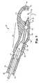
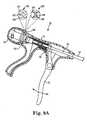
- FIG. 1is a side plan view of a suturing assembly 50 configured to place suture in tissue according to one embodiment.
- Suturing assembly 50includes a handle 52, a shaft 54 coupled to handle 52, and a head 56 coupled to shaft 54.
- Handle 52thus defines a proximal end of suturing assembly 50 and is nearest a user of suturing assembly 50.
- Handle 52includes an actuator 58 communicating with a rod 60 that is disposed within shaft 54.
- actuator 58When actuator 58 is activated, rod 60 moves through shaft 54 to extend a needle 62 stored within a proximal end portion of head 56 axially outward through tissue and toward a distal end 64 of head 56.
- needle 62moves away from the user (who is holding handle 52 at the proximal end of suturing assembly 50) toward distal end 64 of suturing assembly 50.
- a capsule(not shown) is retained within distal end 64, and needle 62 is shaped to frictionally engage and mate with the capsule, remove the capsule from distal end 64, and retract the capsule into the proximal end portion of head 56. In this manner, the suture towed behind the capsule is "thrown" through the tissue.
- Embodiments described belowinclude a guide pin located within head 56 that is configured to disengage the capsule from needle 62.
- Suturing assembly 50is suited for the intracorporeal suturing of tissue during surgery, and in one embodiment is provided as a sterile disposable surgical instrument that is discarded after the surgical procedure. To this end, the components of assembly 50 are selected to be compatible with gas, steam, or radiation sterilization.
- Figure 2is a cross-sectional view of one embodiment of a handle 52.
- handle 52is aligned with a major longitudinal axis A and includes a body 70 extending between a distal end 72 and a proximal end 74, a thumb brace 76 extending laterally from body 70, a trigger 78 spaced apart from thumb brace 76, and a knob 80 coupled to proximal end 74.
- body 70is fabricated from plastic, for example via injection molding.
- Suitable plastic materials for the fabrication of body 70, brace 76, and knob 80include, as examples, polycarbonate, polyethylene, acrylonitrile butadiene styrene, acrylic, or nylon.
- brace 76is integrally molded with a clamshell-style of body 70 and these two components are joined together to retain trigger 78 and knob 80.
- Trigger 78is formed to have sufficient strength to resist bending when activated by the human hand.
- Suitable materials for forming trigger 78include metal such as aluminum or plastics such as polyetherimide or poly-ether-ether-ketone.
- Shaft 54is coupled to distal end 72 of body 70, and rod 60 is disposed within shaft 54 and coupled to trigger 78.
- actuator 58includes trigger 78 attached to rod 60 and a spring 82 disposed within a spring pusher 84 and biased against and an internal rib 86.
- Trigger 78is movable toward thumb brace 76 to move rod 60 in a distal direction longitudinally within shaft 54, which compresses spring 82.
- spring 82extends to push spring pusher 84 proximally, which retracts or returns rod 60 toward proximal end 74.
- Triggeris spaced apart from thumb brace 76 by a distance of approximately 4-12 cm to enable the fingers of the user to comfortably activate trigger 78.
- Trigger 78is disposed at an angle B relative to the longitudinal axis A of body 70, and in an exemplary embodiment the angle B is between 70-110 degrees such that trigger 78 is approximately orthogonal to longitudinal axis A.
- Actuator 58is configured to move rod 60 forward in a distal direction and rearward in a proximal direction within shaft 54. In one embodiment, it is desirable to move rod 60 rearward an additional distance to disengage the suture assembly described below from needle 62 ( Figure 1 ). To facilitate this, rod 60 includes an insert (not shown) that communicates through spring pusher 84 and is captured in window 88. When knob 80 is turned, spring pusher 84 turns and the insert attached to rod 60 is retracted back in a proximal direction due to the angle of window 88, which retracts rod 60 an additional distance into body 70. For example, in one embodiment knob 80 is configured such that a 180 degree clockwise of knob 80 relative to end 74 draws rod 60 an additional distance of about 2 mm into body 70. Although knob 80 is configured to retract rod 60 further into body 70 via a turning motion, other mechanisms such as levers or draw bars for retracting rod 60 incrementally rearward are also acceptable.
- Figure 3is a side view of shaft 54.
- shaft 54includes a substantially rigid aluminum annular tube extending between a proximal end that is attachable to handle 52 ( Figure 1 ) and a distal end that is attachable to head 56.
- Other substantially rigid materialssuch as stainless steel, are also suitable selections for fabricating shaft 54.
- Another embodiment of shaft 54includes a distal end portion associated with distal end 92 that is flexible and configured to bend laterally relative to first section 96 to enable the surgeon to selectively direct head 56 to a desired location.
- shaft 54includes a proximal end 90 that is attachable to handle 52 ( Figure 1 ), a distal end 92 that is attachable to head 56 ( Figure 1 ), and a crimp 94 or a weld 94 connects a first section 96 to a second section 98.
- shaft 54is formed as a thin-walled tube with first section 96 formed of a first material and a second section 98 is formed of a different second material.
- first section 96is formed of 6,000 series aluminum and a second section 98 is formed of 3000 series aluminum, with these two metal sections 96, 98 joined together by crimp / weld 94.
- the 6000 series aluminumis selected to have a shear modulus of a sufficient value to preclude the user from bending first section 96 as instrument 50 is manipulated.
- the shear modulus of first section 96is approximately 30 GN/m 2 .
- the 3000 series aluminumis selected to have a shear modulus of a sufficient value to enable a user to bend the second section 98 with their hands, which enables the user to shape and guide second section 98 (which is attached to head 56) in controlling and guiding the placement of sutures with head 56.
- the shear modulus of second section 98is approximately 10 GN/m 2 .
- the yield strength of first section 96is approximately 30 GN/m 2 .
- the 3000 series aluminumis selected to have a yield strength of a sufficient value to enable a user to bend the second section 98 with their hands, which enables the user to shape and guide second section 98 (which is attached to head 56) in controlling and guiding the placement of sutures with head 56.
- the yield strength of second section 98is approximately 10 GN/m 2 .
- first section 96is for first section 96 to have a length between 4-24 cm and second section 98 to have a length between 1-10 cm. Other lengths for sections 96, 98 are also acceptable.
- crimp / weld 94is provided as a metal peripheral crimp securing first section 96 to second section 98.
- Figure 4is a cross-sectional view of rod 60 disposed within shaft 54.
- Rod 60generally includes a proximal end 100 that couples with push rod 84 ( Figure 2 ) and a distal end 102 that communicates with needle 62.
- proximal end 100 of rod 60is rigid and the remaining portion of rod 60 is formed to include a coiled spring, where multiple coils 104 abut such that rod 60 has sufficient column strength (e.g., along its major axis) to enable rod 60 to activate needle 62 and is provided with flexibility to bend laterally.
- an entire length of rod 60is formed of a coiled stainless steel spring and is constrained within shaft 54 ( Figure 3 ) to provide rod 60 with a column strength configured to resist buckling under axial loads, and the coils 104 are configured to enable head 56 ( Figure 1 ) to flex and move laterally under the application of a radial load.
- the user of instrument 50( Figure 1 ) can bear down on shaft 54 and rod 60 to apply a forward-applied force, while also having the flexibility and control of shaping where head 56 is oriented relative to handle 52.
- rod 60is formed of a coiled stainless steel spring and includes a polyethylene jacket, as one example, disposed around the coiled spring.
- only a leading section 106 of rod 60is formed of coiled springs 104, where leading section 106 corresponds to the flexible second section 98 of shaft 54, such that rod 60 is provided with substantially the same lateral flexibility as shaft 54.
- rod 60is formed of aluminum and configured to have similar flexibility as shaft 54.
- Figure 5is a cross-sectional view of head 56.
- head 56is formed of two mating clamshell components, and the view of Figure 5 is taken with one half of the clamshell structure removed so that the internal features of head 56 are visible.
- Head 56is molded from plastic, for example from a polyether imide plastic sold under the trademark Ultem, or from glass-filled polyether imide plastics also sold under the trademark Ultem.
- head 56includes a proximal end 110 opposite distal end 64, a proximal end portion 112 extending from proximal end 110, and a neck 114 that extends between proximal end portion 112 and distal end 64.
- Head 56is attachable to shaft 54, and in one embodiment includes an opening 120 sized to receive shaft 54 such that rod 60 extends into proximal end portion 112 and couples with a link 122 that is attached to needle 62.
- the distal end 64is not aligned with, but is rather offset radially from longitudinal axis A, to more comfortably position shaft 54 for manipulation by the surgeon as head 56 is engaged with tissue.
- a clevis pin 121connects a proximal end of link 122 to rod 60 and a distal end of link 122 is coupled to needle 62. Movement of rod 60 moves link 122, which moves needle 62 into and out of a needle exit port 123 formed in proximal end portion 112.
- a trace 124that is formed on an interior surface 125 of proximal end portion 112 of head 56, and link 122 is configured to translate and rotate within trace 124 to translate needle 62 along axis A and pitch needle up/down relative to axis A.
- link 122includes a first pin 126 that couples with clevis 121 and a second pin 128 that couples with needle 62. Axial movement of rod 60 translates to axial movement of link 122 and needle 62, and link 122 rotates about pins 126, 128 to shunt a path of needle 62 off of axis A.
- Link 122is thus configured to translate within trace 124 to move needle 62 in/out relative to needle exit port 123, and rotate relative to pins 126, 128 to direct movement of needle 62 up/down relative to longitudinal axis A.
- proximal end portion 112includes a guide pin 130 that defines a bore sized to receive needle 62. Needle 62 is configured to slide through the bore formed in guide pin 130, and guide pin 130 is rotatable to allow needle 62 to pitch relative to longitudinal axis A as needle 62 moves axially, for example as needle 62 moves into engagement with distal end 64.
- Neck 114extends between proximal end portion 112 and distal end 64 and defines a throat 132. Needle 62 is movable from proximal end portion 112, out of needle exit port 123, across throat 132, and into a cavity 134 formed in distal end 64. In one embodiment, distal end 64 and cavity 134 are both radially spaced away from longitudinal axis A, and guide pin 130 rotates to enable needle 62 to move out of the needle exit port 123, pitch upwards, and into cavity 134. In one embodiment, a top surface of neck 114 defines an open, exposed groove configured to receive and guide suture that extends from the capsule 152 ( Figure 6 ) captured in cavity 134 back to handle 52 ( Figure 1 ).
- cavity 134is configured to retain a capsule attached to suture (see Figure 7 ), and needle 62 is configured to penetrate tissue and enter cavity 134, engage the capsule, and pull the capsule through the tissue and into needle exit port 123 to "throw" the suture across throat 132.
- embodiments of head 56include mechanisms configured to linearly direct needle 62 out of needle exit port 123 across throat 132 and into cavity 134 for engagement with the capsule.
- Other embodiments of head 56include mechanisms configured to shunt needle 62 (e.g., pitch needle 62 upward relative to axis A away from needle exit port 123 and into cavity 134 for engagement with the capsule).
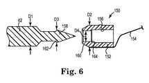
- FIG. 6is a side view of needle 62 aligned for engagement with a suture assembly 150 according to one embodiment.
- Needle 62is preferably machined from metal such as stainless steel or a shape memory alloy such as NITINOL (Nickel Titanium Naval Ordinance Laboratory), as examples.
- Suture assembly 150includes a capsule 152 and suture 154 extending from capsule 152.
- capsule 152is molded from plastic to integrally capture suture 154. Suitable plastic materials for fabricating capsule 152 include polypropylene, polysulfone, urethane, or polyetherimide as examples.
- Suture 154includes monofilament suture, braided suture, coated suture materials or the like, as examples.
- Capsule 152is sized to be deposited and retained in cavity 134 ( Figure 5 ) and defines a recess 156 configured to receive a leading end 158 of needle 62.
- needle 62is shaped to promote secure engagement with capsule 152 and leading end 158 is formed to have a conical point with a shoulder 162 that is sized to be pressed into engagement with a flange 164 of recess 156.
- flange 164that is shaped and sized to frictionally engage (e.g., snap-fit) in a "locked" manner with a shoulder 162 of needle 62 as needle 62 is driven into recess 156.
- Capsule 152is configured to be detached from needle 62 by guide pin 130 ( Figure 5 ) after needle 62 pulls capsule 152 rearward in a proximal direction into head 56.
- the conical point of needle 62is configured to form a channel when advanced through tissue, and capsule 152 is sized to be pulled through the channel in the tissue made by needle 62.
- leading end 160 of capsule 152is chamfered and needle 62 is configured to draw the chamfered (or truncated) end 160 of capsule 152 first through the tissue.
- leading end 160 of capsule 152is a blunt end similar to that illustrated for the trailing end of the capsule 152, and needle 62 is configured to draw the blunt end 160 of capsule 152 blunt end-first through the tissue.
- needle 62has a first diameter D1 and capsule 152 has a diameter D2, were diameter D1 is equal to or greater than diameter D2.
- capsule 152is sized to follow needle 62 and be retracted through the channel formed in the tissue by needle 62.
- Leading end 158 of needle 62is sized to frictionally engage with recess 156 formed in capsule 152.
- leading end 158has a diameter D3 that is slightly greater than a diameter D4 formed in an opening of recess 156. In this manner, when leading end 158 of needle 62 is inserted into recess 156, leading end 158 is forced into and seats within and captures capsule 152.
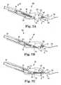
- FIGS 7A-7Fare schematic cross-sectional views illustrating a suturing system 166 including suturing device 50 and suture assembly 150 employed to throw needle 62 from a proximal location to a distal location of head 56, engage needle 62 with a capsule 152/suture 154 of assembly 150, and retract capsule 152/suture 154 through tissue.
- Figure 7Ais a schematic cross-sectional view of system 166 with needle 62 fully retracted within needle exit port 123 of proximal end portion 112 of head 56.
- Capsule 152is seated in cavity 134 with suture 154 trailing distal of head 56.
- distal end 64includes a slot configured to enable the suture 154 to pass through distal end 64 to facilitate loading capsule 152 into cavity 134.
- rod 60 and needle 62are aligned on axis A when needle 62 is retracted into proximal end portion 112 as illustrated, and capsule 152 is aligned on an axis C that is not aligned with axis A.
- Figure 7Bis a schematic cross-sectional view of system 166 with needle 62 partially extending from needle exit port 123 after activation of actuator 58 ( Figure 1 ).
- Moving rod 60 axially in a distal directionmoves needle 62 out of needle exit port 123 in a first direction along axis A.
- distal end 64is radially spaced apart from longitudinal axis A by a distance H, such that the first direction is oriented along axis A, which results in the pathway of needle 62 being offset from cavity 134 by a distance H.
- a portion of needle 62extends from needle exit port 123 partway across throat 132, and guide pin 130 is configured to rotate counter-clockwise to allow the movement of link 122 within trace 124 to shunt the leading end 158 of needle 62 away from the first direction oriented along axis A to a second direction aligned with an axis C that extends through cavity 134.
- Figure 7Cis a schematic cross-sectional view of system 166 including needle 62 shunted away from longitudinal axis A by link 122 and pin 130, moved in a second direction along axis C by rod 60, and engaged with capsule 152.
- Guide pin 130has rotated counterclockwise to allow the movement of link 122 within trace 124 to shunt the direction of needle 62 out of alignment with axis A and into alignment with axis C. Additional forward movement of rod 60 will further direct needle 62 across throat 132 and into engagement with capsule 152.
- needle 62is reversible along the paths coincident with axis C and axis A to retract needle 62 and capsule 152 into needle exit port 123.
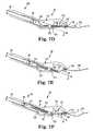
- Figures 7D-7Fare schematic cross-sectional views of needle 62 engaged with capsule 152 and operable to retract and park capsule 152 back in the proximal end portion 112 of head 56.
- Figure 7Dis a schematic view of needle 62 engaged with capsule 152 and retracted along axis C a short distance such that capsule 152 is extracted out of cavity 134 and into throat 132. Additional rearward retraction of rod 60 will cause guide pin 130 to rotate clockwise to allow the movement of link 122 within trace 124 to shunt needle 62 off of axis C and into alignment with axis A. Suture 154 trails behind capsule 152 and out of a backside of cavity 134.
- Figure 7Eis a schematic view of needle 62 partially retracted into proximal end portion 112 of head 56.
- Link 122has moved to a midpoint of trace 124 such that needle 62 and capsule 152 have shunted down into alignment with axis A.
- Retraction of rod 60 axially into shaft 54draws needle 62 and capsule 152 into needle exit port 123.
- Figure 7Fis a schematic view of needle 62 retracted into head 56 with capsule 152 parked in needle exit port 123.
- needle exit port 123is sized to receive capsule 152 such that port 123 forms a capsule garage 123 into which capsule 152 is parked after extraction from cavity 134.
- Rod 60has drawn link 122 into full rearward engagement with trace 124 such that needle 62 is aligned with axis A and retracted into head 56.
- Capsule 152is parked inside needle exit port 123 and suture 154 extends across throat 132, which provides the surgeon with guidance and control of the suture line.
- knob 80is configured to be turned to incrementally retract rod 60 an additional distance into handle 52, which separates needle 62 from capsule 152 that is parked in needle exit port 123.
- the additional retraction of needle 62 by the rearward motion of rod 60causes capsule 152 to be pressed against guide pin 130, which shears capsule 152 off of needle 62.
- Needle 62is thus disengaged from capsule 152, which leaves capsule 152 parked in needle exit port 123.
- the removal of instrument 50 from the surgical sitegives the surgeon access to head 56 for the extraction of capsule 152 from needle exit port 123.
- the surgeonthereafter ties and terminates suture 154 as desired.
- Embodiments of the suturing device described hereinprovide a method of suturing tissue useful in many surgical procedures, including the treatment of pelvic organ prolapse.
- a suturing device suited for the surgical treatment of pelvic organ prolapsethat is operable to suture a scaffold or other support to a ligament or other tissue located relative to the pelvic floor.
- suturesit is desirable to apply sutures to the sacrospinous ligament and/or in the arcus tendineus ligament to attach a synthetic scaffold thereto that is configured to support the pelvic floor and reduce or eliminate the undesirable effects of pelvic organ prolapse.
- FIG 8is a flow diagram 170 of an examplary method of suturing tissue.
- the methodincludes engaging tissue with a suturing head at 172.
- a catheteris placed in the patient's urethra U, along with other recommended, desirable, and preliminary steps in preparation for surgery.
- the patientis typically placed on an operating table in a lithotomy position with buttocks extending just beyond an edge of the table.
- a vaginal incisionfemale
- a perineal incisionmale
- the surgeonwould typically palpate the patient to identify a desired landmark, such as the sacrospinous ligament or arcus tendineus ligament or other tissue landmark.
- the surgeonidentifies the landmark, for example with a finger, and subsequently introduces sterile instrument 50 and engages throat 132 ( Figure 5 ) with the identified landmark.
- the methodincludes driving a needle from a proximal portion of the suturing head through the tissue.
- the surgeonactivates actuator 58 to drive needle 62 out of proximal end portion 112 of head 56, through tissue, and into the identified ligament.
- the methodincludes engaging the capsule retained in the distal end of the suturing head with a needle, the capsule including a length of suture attached thereto.
- the physiciandrives needle 62 through the desired tissue location with actuator 58 until needle 62 engages with capsule 152.
- Needle 62forms a lesion in the tissue, and retracting needle 62 pulls capsule 152 through the lesion with suture 154 following behind.
- the head 56is disengaged from the landmark and suturing device is removed from the patient to enable the physician to access and tie the suture.
- suturing assembly 50( Figure 1 ) is properly disposed of in an approved waste stream of the surgical facility.
- Needle 62is deployed from head 56, and head 56 is compatible with multiple different handle and/or shaft configurations, several of which are described below.
- Figure 9Ais a schematic cross-sectional view of handle 52 including a visual indicator 180.
- Handle 52is similar to the handle illustrated in Figure 2 and includes trigger 78 that is configured to move rod 60 axially forward and backward within shaft 54.
- visual indicator 180is formed as a see-through window 186 that enables a user to look through body 70 of handle 52 to discern a positional state of push rod 60.
- visual indicator 180is configured to indicate a first state in which needle 62 is responsive to actuator 58 and ready to be thrown to engage with capsule 152 ( Figure 7A ), and a second state identifying when knob 80 has been turned to disengage capsule 152 from needle 62 ( Figure 7F ) and needle 62 is not ready to be thrown to engage with another capsule 152.
- knob 80is employed (e.g., turned) to further retract rod 60 into handle 52 and disengage capsule 152 from needle 62.
- knob 80When knob 80 has been turned and capsule 152 has been disengaged from needle 62, rod 60 is "captured” by knob 80 and prevented from moving forward when trigger 78 is activated. Returning knob 80 to its initial position enables trigger 78 to fire (or throw) needle 62 into engagement with cavity 134 and capsule 152 within cavity 134.
- a proximal end 181 of rod 60includes a deployment indicator 182 and a separate retracted indicator 184.
- Indicator 182is configured to indicate that rod 60 is ready to be moved axially forward within shaft 54 to push needle 62 out of needle exit port 123.
- the deployment indicator 182is visible within window 186 the user is informed that rod 60 is ready to deploy needle 62 and capture a capsule 152 (the action of which is termed "throwing a suture").
- Retracting rod 60returns rod 60 to the retracted position indicated in Figure 9A .
- rod 60is drawn incrementally further back into handle 52 by turning knob 80, for example to disengage capsule 152 from needle 62 ( Figure 7F )
- retracted indicator 184becomes visible within window 186.
- the presence of retracted indicator 184 within window 186indicates that needle 62 has been disengaged from capsule 152 and that knob 80 has not been returned to its initial position (and thus, rod 60 is not ready to fire needle 62).
- deployment indicator 182is provided as a first color and retracted indicator 184 is provided as a second color different from the first color.
- deployment indicator 182is green to indicate that needle 62 is ready to be thrown to engage with capsule 152 and retracted indicator 184 is red to indicate that knob 80 has been turned and needle 62 is not in position or ready to be fired toward capsule 152.
- deployment indicator 182is provided as an arrow to indicate that needle 62 is ready to be thrown to engage with capsule 152 and retracted indicator 184 is provided as an X to indicate that knob 80 has been turned and needle 62 is not in position or ready to be fired toward capsule 152.
- Figure 9Bis a cross-sectional view of another embodiment of an indicator 183 for handle 52.
- indicator 183includes a first 183a indicia located on knob 80 and a second 183b indicia located on body 70 of handle 52.
- first 183a indiciais aligned with second 183b indicia when rod 60 is in position to fire needle 62 to engage capsule 152, or when knob 80 has been returned to its initial position to ready rod 60 to fire needle 62 to engage capsule 152.
- first 183a indiciais a semi-circle or a mirror image of second 183b indicia.
- first 183a indiciais not aligned with second 183b indicia, which indicates to the user that needle 62 is not ready to be fired.
- the half-oval of first 183a indiciadoes not aligned with its mirror image of the half-oval of second 183b indicia, as illustrated.
- knob 80may be turned by the user to return it to its initial position in which rod 60 is in position to fire needle 62 to engage capsule 152, in which case 183a becomes aligned with 183b.
- Indicator 183includes color indicators, shapes on handle 52 and knob 80 that mate to indicate alignment of knob 80 with handle 52 (as illustrated), or letters or numbers that indicate alignment and/or non-alignment of knob 80 with handle 52.
- Figure 10is a schematic cross-sectional view of another handle 200 configured for use with suturing device 50 illustrated in Figure 1 .
- Handleis fabricated with materials similar to handle 52 described above.
- handle 200includes a grip 202 coupled to shaft 54, a rod 204 disposed within shaft 54, and a trigger 206 coupled to rod 204 and configured to displace rod 204 axially within shaft 54.
- grip 202includes a fixed collar 208 and rod 204 includes a base 210 that moves relative to collar 208 when trigger 206 is squeezed.
- a biasing member 212is disposed between collar 208 and base 210. Squeezing trigger 206 draws base 210 toward fixed collar 208, which moves rod 204 in a distal direction and stores energy within biasing member 212. Releasing trigger 206 causes biasing member 212 to force base 210 back in a proximal direction to its neutral state. In this manner, handle 200 provides a bike brake-style handle that enables rod 204 to move forward and back within shaft 54 when trigger 206 is activated.
- handle 200is provided in a familiar-to-use "bike brake-style" that provides trigger 206 coupled to grip 202 at an angle between 0-10 degrees relative to the axis of shaft 54.
- this bike brake-style trigger 206is substantially parallel to grip 202.
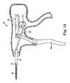
- Figure 11is a schematic cross-sectional view of another handle 220 configured for use with suturing device 50 illustrated in Figure 1 .
- handle 220includes a proximal handle 222, a biasing member 224 disposed within proximal handle 222, a collar 226, a first geared rack 228 attached to collar 226 and communicating with biasing member 224, a second geared rack 230 disposed within proximal handle 222, and a fixed gear 232 disposed between first geared rack 228 and second geared rack 230.
- proximal handle 222is curved to accommodate palm of a user, and collar 226 is configured to be engaged by fingers of the user to pull collar 226 toward handle 222.
- First geared rack 228is fixed relative to collar 226 and second geared rack 230 is attached to push rod 234.
- the geared racks 228, 230move relative to each other by action of gear 230 which is mated between racks 228, 230.
- gear 232rotates clockwise and geared rack 228 moves toward proximal handle 222, which compresses biasing member 224.
- geared rack 230moves in the distal direction (e.g., forward, along with handle 222), which pushes rod 234 in a forward direction. Since rod 234 is coupled to needle 62 ( Figure 5 ), needle 62 is thus moved forward (e.g., "thrown") when collar 226 is squeezed toward the arched proximal handle 222 of handle 220. Biasing member 224 forces collar 226 away from handle 222 when the squeezing force is relaxed, this "reloads" collar 226 to subsequently throw additional sutures.
- the broad area of proximal handle 222comfortably distributes the applied force across the hand of the user and collar 226 provides positive engagement with the fingers.
- Figure 12is a schematic cross-sectional view of another handle 240 configured for use with the suturing device 50 illustrated in Figure 1 .
- Handle 240is configured such that squeezing motion delivered laterally relative to shaft 54 results in axial movement of needle 62 from head 56 ( Figure 5 ).
- handle 240includes a grip 242 defining a distal end portion 244 opposite a proximal end 246, a squeezable member 248 pinned to the distal end portion 244 of grip 242, and an actuator 250 that is configured to translate the lateral squeezing movement of squeezable member 248 to axial movement of a rod 254 disposed within shaft 54.
- actuator 250includes a first gear 260 disposed within grip 242 and mated to a second gear 262, and squeezable member 248 includes a geared rack 264 that is engaged with the second gear 262.
- Rod 254is coupled with first gear 260.
- gear 260is attached to a pair of cables that are spaced 180 degrees apart on round gear 260.
- the cablesextend to a forward gear or pulley located within head 56 ( Figure 5 ).
- the cablesare balanced in a pulley arrangement such that rotation of gear 260 clockwise tensions the upper cable, which rotates the forward gear clockwise to tension the lower cable.
- the cablesreplace the push/pull function of rod 254.
- grip 242is fabricated from plastic similar to the handles for instrument 50 described above and is molded to include an ergonomic tear-drop shape.
- Figure 13is a schematic view of another handle 280 configured for use with suturing device 50 illustrated in Figure 1 .
- Handle 280is similar to handle 52 ( Figure 1 ) and includes a trigger 286 that is configured to eject needle 62 from head 56 with a first squeeze of trigger 286 and retract needle 62 into head 56 with a subsequent squeeze of trigger 286.
- handle 280includes a uni-directional gear 282 coupled to a rack 284 that is provided with two degrees of freedom.
- trigger 286is pinned to rack 284, and a link 288 is pinned between gear 282 and rod 60.
- Gear 282is configured to rotate in only one direction (i.e., uni-directionally), which in this embodiment is counter-clockwise.
- link 288is positioned at the 3 o'clock position of gear 282 (e.g., at the top), and squeezing trigger 286 rotates gear 282 counter-clockwise to the 9 o'clock position, which displaces link 288 distally forward to push rod 60 forward.
- Releasing trigger 286causes rack 284 to lift and skip over the teeth in gear 282 (i.e., without gear 282 and rack 284 meshing), leaving link 288 at the 9 o'clock position.
- rack 284has at least two degrees of freedom: laterally left and right as oriented in Figure 13 and up/down to disengage from gear 282.
- rack 284is retracted proximally backwards relative to gear 282 without rotating gear 282.
- a second squeeze of trigger 286again draws rack 284 forward and into engagement with gear 282, rotating gear 282 counter-clockwise, which draws link 288 rearward from the 9 o'clock position back and up to the 3 o'clock position to retract push rod 60 within shaft 54.
- handle 280provides a double action trigger 286 configured to throw a suture by moving needle 62 forward with a first pull of trigger to 86 and retract needle with a second pull of trigger 286.
- shaft 54is provided as a rigid shaft. However, the surgeon may desire to adjust the location of head 56 as a suture is thrown, or as subsequent sutures are placed.
- Instrument 50provides for positional flexibility of head 56, for example via flexible end section 98 of shaft 54 ( Figure 3 ). Additional embodiments of flexible shafts that provide the surgeon with flexibility in placing sutures are described below.
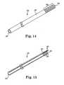
- FIG 14is a perspective view of another embodiment of a shaft 300 configured for use with suturing instrument 50 illustrated in Figure 1 .
- Shaft 300includes a proximal end 302 that is attachable to a handle (such as handle 52 in Figure 1 ) and a distal end 304 that couples with a suture throwing head (such as head 56 in Figure 1 ).
- a distal end portion 306 of shaft 300includes a corrugated section that provides distal end portion 306 with lateral flexibility relative to section 308.
- shaft 300is fabricated from stainless steel, and distal portion 306 is provided with an accordion-style corrugated structure that provides lateral flexibility for distal end 304 of shaft 300.
- Suitable metals for shaft 300include aluminum, steel including stainless steel, highly malleable metal such as copper, or other such suitable metals.
- FIG 15is a perspective view of another embodiment of a shaft 320 configured for use with suturing instrument 50 illustrated in Figure 1 .
- Shaft 320includes a proximal end 322 that is attachable to a handle (such as handle 52 in Figure 1 ) opposite a distal end 324 that couples with a suture throwing head (such as head 56 in Figure 1 ), and a distal end portion 326 including one or more flexible coils 328.
- coils 328are attached to an end portion 330 of shaft 320, for example by soldering or welding.
- coils 328are disposed over a rigid end portion of shaft 320 and crimped in place.
- coils 328are integrally formed with shaft 320, and in a separate embodiment coils 328 are provided separate from shaft 320 and subsequently attached thereto.
- distal end portion 326 of shaft 320is provided with flexibility in the lateral direction that enables the surgeon to move head 56 laterally relative to the longitudinal axis of shaft 320.
- coils 328are formed from copper and attached to end portion 330 of a stainless steel shaft 320.
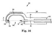
- Figure 16is a cross-sectional view of another head 350.
- Head 350is coupled to shaft 54 such that rod 60 extends through a portion of head 350 to couple with needle 62.
- head 350includes a proximal end 352 opposite a distal end 354, a proximal end portion 356 extending from proximal end 352, and a neck 358 that extends between proximal end portion 356 and distal end 354.
- a throat 360is formed between proximal end portion 356 and distal end 354, where proximal end portion 356 defines a needle exit port 362 through which needle 62 moves.
- head 350is provided as a linear head having a distal end 354 that defines a cavity 364 aligned with the major longitudinal axis A of the suturing device. Cavity 364 is sized and configured to retain capsule 152 of suturing assembly 150 ( Figure 7 ).
- needle 62is provided as a substantially straight needle that is aligned on axis A of shaft 54 when stowed (e.g., stored or parked) within proximal portion 356 of head 350. Needle 62 moves longitudinally out of needle exit port 362 along a substantially linear (straight) line and traverses throat 360 by traveling along axis A. As described above, needle 62 is configured to engage capsule 152, remove capsule 152 from cavity 364, and pull capsule 152 (and suture attached to capsule 152) proximally back across throat 360 to suture tissue engaged in throat 360.
- Head 56( Figure 5 ) provides an offset distal end 64 and head 350 provides an example of a linear arrangement between distal end portion 356 and distal end 354.
- rod 60is rigidly coupled to needle 62.
- a linkis coupled between rod 60 and needle 62, where the link translates within a channel to move needle 62 along axis A and into engagement with capsule 152 ( Figure 7 ) that is retained within cavity 364.
- rod 60is rigidly coupled with needle 62 and configured to drive needle 62 directly across throat 360 and into engagement with a capsule/suture assembly placed in cavity 364.
- Other mechanisms for linearly delivering needle 62 from proximal end portion 356 of head 350are also acceptable.
- Figure 17is a cross-sectional view of another head 400.
- Head 400is configured to be coupled to shaft 54 such that rod 60 extends through a portion of head 400 to couple with a linkage 402 that communicates with a curved needle 404.
- Head 400includes a proximal end 410 opposite a distal end 412, a proximal end portion 414 extending from proximal end 410, and a neck 416 that extends between proximal end portion 414 and distal end 412.
- a throat 418is formed between proximal end portion 414 and distal end 412, where proximal end portion 414 defines a needle exit port 420 through which curved needle 404 exits proximal end portion 414.
- distal end 412defines a cavity 422 that is sized and configured to retain capsule 152 of suturing assembly 150 ( Figure 7 ).
- Suture 154 ( Figure 7 ) of suture assembly 150is directed over distal end 412 and proximal end portion 414 for management by the surgeon near the handle located proximal of the instrument.
- Curved needle 404moves clockwise in this example out of needle exit port 420 and includes a leading end 424 that is configured to engage with capsule 152, remove capsule 152 from cavity 422, and pull capsule 152 (and suture attached to capsule 152) counter-clockwise back across throat 418 to suture tissue engaged in throat 418.
- linkage 402includes a first link 430 and a second link 440, where first link 430 includes a pin 432 coupled to rod 60 and a second pin 434 coupled to second link 440.
- Second link 440has a pin 442 that defines a pivot point about which link 440 and needle 404 rotates.
- a trailing end 450 of curved needle 404is coupled to a juncture of first link 430 and second link 440 by pin 434.
- Rod 60is retractable, for example by actuator 58 illustrated in Figure 1 . Movement of rod 60 toward distal end 412 of head 400 moves first link 430 in a forward direction, causing second link 440 to rotate about pivot point 442. In particular, pin 434 in second link 440 moves in a counter-clockwise motion relative to pivot point 442. The counter-clockwise motion of pin 434 draws curved needle 404 in a counter-clockwise retracting motion that opens throat 418. Conversely, rod 60 is movable backwards in a proximal direction that draws pin 432 and link 430 rearward, which rotates pin 434 clockwise.
- Head 400thus examplifies a reversed curved needle suture thrower that is configured to move curved needle 404 away from proximal end portion 414 in an arc, across throat 418, and into engagement with capsule 152 ( Figure 7 ) retained within cavity 422. Movement of rod 60 as described above retracts capsule from cavity 422 and pulls the capsule back into needle exit port 420.
- a suturing systemprovides a suturing instrument having a needle housed in a proximal end portion of a head, where the needle is movable longitudinally out of the proximal end portion of the head through tissue to subsequently grasp a cap attached to suture.
- the needleretracts after engaging the cap and pulls the suture through the lesion formed by the needle in the tissue to efficiently throw and retrieve suture.
- a trailing end 450 of curved needle 404is coupled to a juncture of first link 430 and second link 440 by pin 434.
- Rod 60is retractable, for example by actuator 58 illustrated in Figure 1 . Movement of rod 60 toward distal end 412 of head 400 moves first link 430 in a forward direction, causing second link 440 to rotate about pivot point 442. In particular, pin 434 in second link 440 moves in a counter-clockwise motion relative to pivot point 442. The counter-clockwise motion of pin 434 draws curved needle 404 in a counter-clockwise retracting motion that opens throat 418. Conversely, rod 60 is movable backwards in a proximal direction that draws pin 432 and link 430 rearward, which rotates pin 434 clockwise.
- Head 400thus provides a reversed curved needle suture thrower that is configured to move curved needle 404 away from proximal end portion 414 in an arc, across throat 418, and into engagement with capsule 152 ( Figure 7 ) retained within cavity 422. Movement of rod 60 as described above retracts capsule from cavity 422 and pulls the capsule back into needle exit port 420.
- a suturing systemprovides a suturing instrument having a needle housed in a proximal end portion of a head, where the needle is movable longitudinally out of the proximal end portion of the head through tissue to subsequently grasp a cap attached to suture.
- the needleretracts after engaging the cap and pulls the suture through the lesion formed by the needle in the tissue to efficiently throw and retrieve suture.
Landscapes
- Health & Medical Sciences (AREA)
- Life Sciences & Earth Sciences (AREA)
- Surgery (AREA)
- Heart & Thoracic Surgery (AREA)
- Engineering & Computer Science (AREA)
- Biomedical Technology (AREA)
- Nuclear Medicine, Radiotherapy & Molecular Imaging (AREA)
- Medical Informatics (AREA)
- Molecular Biology (AREA)
- Animal Behavior & Ethology (AREA)
- General Health & Medical Sciences (AREA)
- Public Health (AREA)
- Veterinary Medicine (AREA)
- Surgical Instruments (AREA)
- Portable Nailing Machines And Staplers (AREA)
Description
- Intracorporeal suturing of tissue during surgery presents challenges to the surgeon in that the surgeon is called upon to manipulate suturing instruments within the confines of a relatively small incision formed in the patient's body. In some cases, the surgeon digitally palpates a desired location for placement of the suture and is unable to see the suture site.
EP1629780 discloses an endoscopic tissue apposition device describing an embodiment wherein a first or carrier needle having a hollow, beveled tip extending towards a vacuum chamber is disposed in a working channel. The beveled tip of the carrier needle is configured to receive a relatively shorter second or punch needle disposed within a holding chamber located on the distal end of the endoscope, on the opposite or distal side of the vacuum chamber.WO 2005/037152 discloses an example of a single device that may be used for modifying regions of surface tissue and to join modified tissue surfaces. A cutting and suturing device is shown that may be used for slicing a layer of tissue from the interior of the stomach and passing a suture through a portion of the remaining tissue.US 2007/270885 discloses a suturing apparatus comprising a first jaw and a second jaw movable with respect to each other. A bendable needle is carried by the first jaw and adapted to carry a suture. The needle is movable between a first position wherein the needle is substantially housed within the jaw and a second position wherein a distal portion of the needle protrudes from the first jaw.- Improved suturing instruments and improved methods of delivering sutures would be welcomed by the surgical staff.
- One aspect provides a suturing assembly configured to place suture in tissue. The suturing assembly includes a handle having an actuator, a shaft coupled to the handle, and a head coupled to the shaft. The head includes a proximal portion housing a needle movable through a needle exit port and a distal end spaced apart from the proximal portion by a throat, the distal end defining a cavity. The actuator is configured to move the needle out of the needle exit port formed in the proximal portion of the head and across the throat to engage a capsule disposed in the cavity formed in the distal end of the head, where the capsule is attached to the suture.
- The accompanying drawings are included to provide a further understanding of embodiments and are incorporated in and constitute a part of this specification. The drawings illustrate embodiments and together with the description serve to explain principles of embodiments. Other embodiments and many of the intended advantages of embodiments will be readily appreciated as they become better understood by reference to the following detailed description. The elements of the drawings are not necessarily to scale relative to each other. Like reference numerals designate corresponding similar parts.
Figure 1 is a side plan view of a suturing instrument according to one embodiment.Figure 2 is a cross-sectional view of one embodiment of a handle of the suturing instrument illustrated inFigure 1 .Figure 3 is a side view of one embodiment of a shaft of the suturing instrument illustrated inFigure 1 .Figure 4 is a cross-sectional view of one embodiment of a push rod disposed within the shaft illustrated inFigure 3 .Figure 5 is a cross-sectional view of a head of the suturing instrument illustrated inFigure 1 including a movable needle according to one embodiment.Figure 6 is a cross-sectional view of a suture assembly including suture attached to a capsule that is configured to couple with a needle of the suturing instrument illustrated inFigure 1 according to one embodiment.Figure 7A is a schematic cross-sectional view of the head of the suturing instrument illustrated inFigure 5 with the needle retracted within the head according to one embodiment.Figure 7B is a cross-sectional view of the head of the suturing instrument illustrated inFigure 5 with the needle partially extending from an exit port of the head according to one embodiment.Figure 7C is a cross-sectional view of the head of the suturing instrument illustrated inFigure 5 with the needle thrown into the distal end of the head and engaged with the suture assembly illustrated inFigure 6 according to one embodiment.Figures 7D-7F are schematic cross-sectional views of the needle of the suturing instrument illustrated inFigure 1 engaged with the suture assembly and retracting a capsule of the suture assembly back into a proximal end portion of the head according to one embodiment.Figure 8 is a flow diagram of an examplary method of suturing tissue.Figure 9A is a cross-sectional view of another embodiment of a handle configured for use with the suturing instrument illustrated inFigure 1 .Figure 9B is a cross-sectional view of another embodiment of a handle configured for use with the suturing instrument illustrated inFigure 1 .Figure 10 is a cross-sectional view of another embodiment of a handle configured for use with the suturing instrument illustrated inFigure 1 .Figure 11 is a cross-sectional view of another embodiment of a handle configured for use with the suturing instrument illustrated inFigure 1 .Figure 12 is a cross-sectional view of another embodiment of a handle configured for use with the suturing instrument illustrated inFigure 1 .Figure 13 is a cross-sectional view of another embodiment of a handle configured for use with the suturing instrument illustrated inFigure 1 .Figure 14 is a perspective view of another embodiment of a shaft configured for use with the suturing instrument illustrated inFigure 1 .Figure 15 is a cross-sectional view of another embodiment of a shaft configured for use with the suturing instrument illustrated inFigure 1 .Figure 16 is a cross-sectional view of an examplary head.Figure 17 is a cross-sectional view of an examplary head.- The invention is defined in claim 1. Preferred embodiments are recited in the dependent claims.
- In the following Detailed Description, reference is made to the accompanying drawings, which form a part hereof, and in which is shown by way of illustration specific embodiments in which the invention may be practiced. In this regard, directional terminology, such as "top," "bottom," "front," "back," "leading," "trailing," etc., is used with reference to the orientation of the Figure(s) being described. Because components of embodiments can be positioned in a number of different orientations, the directional terminology is used for purposes of illustration and is in no way limiting. It is to be understood that other embodiments may be utilized and structural or logical changes may be made without departing from the scope of the present invention. The following detailed description, therefore, is not to be taken in a limiting sense, and the scope of the present invention is defined by the appended claims.
- It is to be understood that the features of the various exemplary embodiments described herein may be combined with each other, unless specifically noted otherwise.
- Tissue includes soft tissue, which includes dermal tissue, sub-dermal tissue, ligaments, tendons, or membranes. As employed in this specification, the term "tissue" does not include bone.
- In this specification, shunt means to move an object away from a first axis to another axis that is different from the first axis. For example, in one embodiment a suturing device includes a needle that is moved in a first direction (e.g., along a longitudinal axis) and is subsequently moved in a second direction different from the first direction (i.e., away from the longitudinal axis); thus the needle is shunted away from a longitudinal axis when deployed from the device.
- In this specification, end means endmost and end portion means that segment that is adjacent to and extends from the end. For example, a proximal end is that end location of a handheld instrument that is nearest a user, and a proximal end portion is that segment (e.g., a handle of the handheld instrument) that is adjacent to and extends distally away from the proximal end.
- Embodiments provide a suturing assembly having a needle housed in a proximal end portion of a head of the assembly, where the needle is deployed longitudinally out of the proximal end portion of the head through a mass of tissue and subsequently grasps a suture assembly. The needle retracts after engaging the suture assembly and pulls the suture assembly through the needle-hole (e.g., lesion) formed in the tissue. In this manner, the suturing assembly reaches through the tissue, grasps the suture assembly, and retracts the suture assembly through the tissue to complete a "stitch" in the tissue.
- In one embodiment, a suture system is provided that includes the suture assembly and a capsule that is attached to a length of suture. Embodiments of the suturing assembly include a head having a distal end that defines a cavity sized to retain the capsule. A needle is housed within a proximal end portion of the head and is movable from a needle exit port into the cavity formed in the distal end of the head. The needle is configured to engage the capsule of the suture assembly.
- Also disclosed is a suturing assembly having a linear head that is configured to throw a needle longitudinally out of a needle exit port, across a throat space, and into a cavity formed in a distal end of the linear head.
- Embodiments provide a suturing assembly having a head with a radially offset distal end, where the head is configured to throw a needle longitudinally in a first direction through a needle exit port, shunt the needle away from the longitudinal axis in a second direction different from the first direction, and into the cavity formed in the radially offset distal end.
- Embodiments provide a suturing assembly configured to throw a needle into frictional engagement with a capsule towing a length of suture. The suturing assembly places a stitch in the tissue each time the capsule is retrieved, and the surgeon, upon seeing the retrieved capsule, is provided with positive visual feedback of the successful application of the suture.
Figure 1 is a side plan view of asuturing assembly 50 configured to place suture in tissue according to one embodiment.Suturing assembly 50 includes ahandle 52, ashaft 54 coupled to handle 52, and ahead 56 coupled toshaft 54.Handle 52 thus defines a proximal end of suturingassembly 50 and is nearest a user ofsuturing assembly 50.Handle 52 includes anactuator 58 communicating with arod 60 that is disposed withinshaft 54. When actuator 58 is activated,rod 60 moves throughshaft 54 to extend aneedle 62 stored within a proximal end portion ofhead 56 axially outward through tissue and toward adistal end 64 ofhead 56. Thus,needle 62 moves away from the user (who is holdinghandle 52 at the proximal end of suturing assembly 50) towarddistal end 64 ofsuturing assembly 50.- In one embodiment, a capsule (not shown) is retained within
distal end 64, andneedle 62 is shaped to frictionally engage and mate with the capsule, remove the capsule fromdistal end 64, and retract the capsule into the proximal end portion ofhead 56. In this manner, the suture towed behind the capsule is "thrown" through the tissue. Embodiments described below include a guide pin located withinhead 56 that is configured to disengage the capsule fromneedle 62. Suturing assembly 50 is suited for the intracorporeal suturing of tissue during surgery, and in one embodiment is provided as a sterile disposable surgical instrument that is discarded after the surgical procedure. To this end, the components ofassembly 50 are selected to be compatible with gas, steam, or radiation sterilization.Figure 2 is a cross-sectional view of one embodiment of ahandle 52. In one embodiment, handle 52 is aligned with a major longitudinal axis A and includes abody 70 extending between adistal end 72 and aproximal end 74, athumb brace 76 extending laterally frombody 70, atrigger 78 spaced apart fromthumb brace 76, and aknob 80 coupled toproximal end 74.- In one embodiment,
body 70 is fabricated from plastic, for example via injection molding. Suitable plastic materials for the fabrication ofbody 70,brace 76, andknob 80 include, as examples, polycarbonate, polyethylene, acrylonitrile butadiene styrene, acrylic, or nylon. In one embodiment, brace 76 is integrally molded with a clamshell-style ofbody 70 and these two components are joined together to retaintrigger 78 andknob 80.Trigger 78 is formed to have sufficient strength to resist bending when activated by the human hand. Suitable materials for formingtrigger 78 include metal such as aluminum or plastics such as polyetherimide or poly-ether-ether-ketone. Shaft 54 is coupled todistal end 72 ofbody 70, androd 60 is disposed withinshaft 54 and coupled to trigger 78. In one embodiment,actuator 58 includestrigger 78 attached torod 60 and aspring 82 disposed within a spring pusher 84 and biased against and aninternal rib 86.Trigger 78 is movable towardthumb brace 76 to moverod 60 in a distal direction longitudinally withinshaft 54, which compressesspring 82. Whentrigger 78 is released,spring 82 extends to push spring pusher 84 proximally, which retracts or returnsrod 60 towardproximal end 74. Trigger is spaced apart fromthumb brace 76 by a distance of approximately 4-12 cm to enable the fingers of the user to comfortably activatetrigger 78.Trigger 78 is disposed at an angle B relative to the longitudinal axis A ofbody 70, and in an exemplary embodiment the angle B is between 70-110 degrees such thattrigger 78 is approximately orthogonal to longitudinal axis A.Actuator 58 is configured to moverod 60 forward in a distal direction and rearward in a proximal direction withinshaft 54. In one embodiment, it is desirable to moverod 60 rearward an additional distance to disengage the suture assembly described below from needle 62 (Figure 1 ). To facilitate this,rod 60 includes an insert (not shown) that communicates through spring pusher 84 and is captured inwindow 88. Whenknob 80 is turned, spring pusher 84 turns and the insert attached torod 60 is retracted back in a proximal direction due to the angle ofwindow 88, which retractsrod 60 an additional distance intobody 70. For example, in oneembodiment knob 80 is configured such that a 180 degree clockwise ofknob 80 relative to end 74 drawsrod 60 an additional distance of about 2 mm intobody 70. Althoughknob 80 is configured to retractrod 60 further intobody 70 via a turning motion, other mechanisms such as levers or draw bars for retractingrod 60 incrementally rearward are also acceptable.Figure 3 is a side view ofshaft 54. One suitable embodiment ofshaft 54 includes a substantially rigid aluminum annular tube extending between a proximal end that is attachable to handle 52 (Figure 1 ) and a distal end that is attachable to head 56. Other substantially rigid materials, such as stainless steel, are also suitable selections for fabricatingshaft 54. Another embodiment ofshaft 54 includes a distal end portion associated withdistal end 92 that is flexible and configured to bend laterally relative tofirst section 96 to enable the surgeon to selectivelydirect head 56 to a desired location.- For example, one embodiment of
shaft 54 includes aproximal end 90 that is attachable to handle 52 (Figure 1 ), adistal end 92 that is attachable to head 56 (Figure 1 ), and acrimp 94 or aweld 94 connects afirst section 96 to asecond section 98. In one embodiment,shaft 54 is formed as a thin-walled tube withfirst section 96 formed of a first material and asecond section 98 is formed of a different second material. In an exemplary embodiment,first section 96 is formed of 6,000 series aluminum and asecond section 98 is formed of 3000 series aluminum, with these twometal sections weld 94. The 6000 series aluminum is selected to have a shear modulus of a sufficient value to preclude the user from bendingfirst section 96 asinstrument 50 is manipulated. For example, in one embodiment the shear modulus offirst section 96 is approximately 30 GN/m2. The 3000 series aluminum is selected to have a shear modulus of a sufficient value to enable a user to bend thesecond section 98 with their hands, which enables the user to shape and guide second section 98 (which is attached to head 56) in controlling and guiding the placement of sutures withhead 56. For example, in one embodiment the shear modulus ofsecond section 98 is approximately 10 GN/m2. In another example, in one embodiment the yield strength offirst section 96 is approximately 30 GN/m2. The 3000 series aluminum is selected to have a yield strength of a sufficient value to enable a user to bend thesecond section 98 with their hands, which enables the user to shape and guide second section 98 (which is attached to head 56) in controlling and guiding the placement of sutures withhead 56. For example, in one embodiment the yield strength ofsecond section 98 is approximately 10 GN/m2. - One example of suitable lengths for
sections first section 96 to have a length between 4-24 cm andsecond section 98 to have a length between 1-10 cm. Other lengths forsections weld 94 is provided as a metal peripheral crimp securingfirst section 96 tosecond section 98. Figure 4 is a cross-sectional view ofrod 60 disposed withinshaft 54.Rod 60 generally includes aproximal end 100 that couples with push rod 84 (Figure 2 ) and adistal end 102 that communicates withneedle 62. In one embodiment,proximal end 100 ofrod 60 is rigid and the remaining portion ofrod 60 is formed to include a coiled spring, wheremultiple coils 104 abut such thatrod 60 has sufficient column strength (e.g., along its major axis) to enablerod 60 to activateneedle 62 and is provided with flexibility to bend laterally. In one embodiment, an entire length ofrod 60 is formed of a coiled stainless steel spring and is constrained within shaft 54 (Figure 3 ) to providerod 60 with a column strength configured to resist buckling under axial loads, and thecoils 104 are configured to enable head 56 (Figure 1 ) to flex and move laterally under the application of a radial load. In this manner, the user of instrument 50 (Figure 1 ) can bear down onshaft 54 androd 60 to apply a forward-applied force, while also having the flexibility and control of shaping wherehead 56 is oriented relative to handle 52.- In one embodiment,
rod 60 is formed of a coiled stainless steel spring and includes a polyethylene jacket, as one example, disposed around the coiled spring. - In one embodiment, only a leading
section 106 ofrod 60 is formed ofcoiled springs 104, where leadingsection 106 corresponds to the flexiblesecond section 98 ofshaft 54, such thatrod 60 is provided with substantially the same lateral flexibility asshaft 54. - In one embodiment,
rod 60 is formed of aluminum and configured to have similar flexibility asshaft 54. Figure 5 is a cross-sectional view ofhead 56. In one embodiment,head 56 is formed of two mating clamshell components, and the view ofFigure 5 is taken with one half of the clamshell structure removed so that the internal features ofhead 56 are visible.Head 56 is molded from plastic, for example from a polyether imide plastic sold under the trademark Ultem, or from glass-filled polyether imide plastics also sold under the trademark Ultem.- In one embodiment,
head 56 includes aproximal end 110 oppositedistal end 64, aproximal end portion 112 extending fromproximal end 110, and aneck 114 that extends betweenproximal end portion 112 anddistal end 64.Head 56 is attachable toshaft 54, and in one embodiment includes anopening 120 sized to receiveshaft 54 such thatrod 60 extends intoproximal end portion 112 and couples with alink 122 that is attached toneedle 62. Thedistal end 64 is not aligned with, but is rather offset radially from longitudinal axis A, to more comfortably positionshaft 54 for manipulation by the surgeon ashead 56 is engaged with tissue. - In one embodiment, a
clevis pin 121 connects a proximal end oflink 122 torod 60 and a distal end oflink 122 is coupled toneedle 62. Movement ofrod 60 moves link 122, which movesneedle 62 into and out of aneedle exit port 123 formed inproximal end portion 112. In one embodiment, atrace 124 that is formed on aninterior surface 125 ofproximal end portion 112 ofhead 56, and link 122 is configured to translate and rotate withintrace 124 to translateneedle 62 along axis A and pitch needle up/down relative to axis A. For example, in oneembodiment link 122 includes afirst pin 126 that couples withclevis 121 and asecond pin 128 that couples withneedle 62. Axial movement ofrod 60 translates to axial movement oflink 122 andneedle 62, and link 122 rotates aboutpins needle 62 off of axis A. Link 122 is thus configured to translate withintrace 124 to moveneedle 62 in/out relative toneedle exit port 123, and rotate relative topins needle 62 up/down relative to longitudinal axis A. In one embodimentproximal end portion 112 includes aguide pin 130 that defines a bore sized to receiveneedle 62.Needle 62 is configured to slide through the bore formed inguide pin 130, andguide pin 130 is rotatable to allowneedle 62 to pitch relative to longitudinal axis A asneedle 62 moves axially, for example asneedle 62 moves into engagement withdistal end 64.Neck 114 extends betweenproximal end portion 112 anddistal end 64 and defines athroat 132.Needle 62 is movable fromproximal end portion 112, out ofneedle exit port 123, acrossthroat 132, and into acavity 134 formed indistal end 64. In one embodiment,distal end 64 andcavity 134 are both radially spaced away from longitudinal axis A, andguide pin 130 rotates to enableneedle 62 to move out of theneedle exit port 123, pitch upwards, and intocavity 134. In one embodiment, a top surface ofneck 114 defines an open, exposed groove configured to receive and guide suture that extends from the capsule 152 (Figure 6 ) captured incavity 134 back to handle 52 (Figure 1 ).- As described below,
cavity 134 is configured to retain a capsule attached to suture (seeFigure 7 ), andneedle 62 is configured to penetrate tissue and entercavity 134, engage the capsule, and pull the capsule through the tissue and intoneedle exit port 123 to "throw" the suture acrossthroat 132. As described below, embodiments ofhead 56 include mechanisms configured to linearlydirect needle 62 out ofneedle exit port 123 acrossthroat 132 and intocavity 134 for engagement with the capsule. Other embodiments ofhead 56 include mechanisms configured to shunt needle 62 (e.g.,pitch needle 62 upward relative to axis A away fromneedle exit port 123 and intocavity 134 for engagement with the capsule). Figure 6 is a side view ofneedle 62 aligned for engagement with asuture assembly 150 according to one embodiment.Needle 62 is preferably machined from metal such as stainless steel or a shape memory alloy such as NITINOL (Nickel Titanium Naval Ordinance Laboratory), as examples.Suture assembly 150 includes acapsule 152 andsuture 154 extending fromcapsule 152. In one embodiment,capsule 152 is molded from plastic to integrally capturesuture 154. Suitable plastic materials for fabricatingcapsule 152 include polypropylene, polysulfone, urethane, or polyetherimide as examples.Suture 154 includes monofilament suture, braided suture, coated suture materials or the like, as examples.Capsule 152 is sized to be deposited and retained in cavity 134 (Figure 5 ) and defines arecess 156 configured to receive aleading end 158 ofneedle 62. In one embodiment,needle 62 is shaped to promote secure engagement withcapsule 152 andleading end 158 is formed to have a conical point with ashoulder 162 that is sized to be pressed into engagement with aflange 164 ofrecess 156. For example,flange 164 that is shaped and sized to frictionally engage (e.g., snap-fit) in a "locked" manner with ashoulder 162 ofneedle 62 asneedle 62 is driven intorecess 156.Capsule 152 is configured to be detached fromneedle 62 by guide pin 130 (Figure 5 ) afterneedle 62 pullscapsule 152 rearward in a proximal direction intohead 56.- The conical point of
needle 62 is configured to form a channel when advanced through tissue, andcapsule 152 is sized to be pulled through the channel in the tissue made byneedle 62. In one embodiment, leadingend 160 ofcapsule 152 is chamfered andneedle 62 is configured to draw the chamfered (or truncated)end 160 ofcapsule 152 first through the tissue. In one embodiment, leadingend 160 ofcapsule 152 is a blunt end similar to that illustrated for the trailing end of thecapsule 152, andneedle 62 is configured to draw theblunt end 160 ofcapsule 152 blunt end-first through the tissue. - For example, in one
embodiment needle 62 has a first diameter D1 andcapsule 152 has a diameter D2, were diameter D1 is equal to or greater than diameter D2. In this manner,capsule 152 is sized to followneedle 62 and be retracted through the channel formed in the tissue byneedle 62. - Leading
end 158 ofneedle 62 is sized to frictionally engage withrecess 156 formed incapsule 152. For example, in oneembodiment leading end 158 has a diameter D3 that is slightly greater than a diameter D4 formed in an opening ofrecess 156. In this manner, when leadingend 158 ofneedle 62 is inserted intorecess 156, leadingend 158 is forced into and seats within and capturescapsule 152. Figures 7A-7F are schematic cross-sectional views illustrating asuturing system 166 includingsuturing device 50 andsuture assembly 150 employed to throwneedle 62 from a proximal location to a distal location ofhead 56, engageneedle 62 with acapsule 152/suture 154 ofassembly 150, and retractcapsule 152/suture 154 through tissue.Figure 7A is a schematic cross-sectional view ofsystem 166 withneedle 62 fully retracted withinneedle exit port 123 ofproximal end portion 112 ofhead 56.Capsule 152 is seated incavity 134 withsuture 154 trailing distal ofhead 56. In one embodiment, it is recommended that the surgeon direct a trailing end ofsuture 154 overdistal end 64 ofhead 56 and back toward a proximal end ofshaft 54 for ease of managingsuture assembly 150 during the procedure. For example, one embodiment ofdistal end 64 includes a slot configured to enable thesuture 154 to pass throughdistal end 64 to facilitateloading capsule 152 intocavity 134. In one embodiment,rod 60 andneedle 62 are aligned on axis A whenneedle 62 is retracted intoproximal end portion 112 as illustrated, andcapsule 152 is aligned on an axis C that is not aligned with axis A.Figure 7B is a schematic cross-sectional view ofsystem 166 withneedle 62 partially extending fromneedle exit port 123 after activation of actuator 58 (Figure 1 ). Movingrod 60 axially in a distal direction movesneedle 62 out ofneedle exit port 123 in a first direction along axis A. In one embodiment,distal end 64 is radially spaced apart from longitudinal axis A by a distance H, such that the first direction is oriented along axis A, which results in the pathway ofneedle 62 being offset fromcavity 134 by a distance H. A portion ofneedle 62 extends fromneedle exit port 123 partway acrossthroat 132, andguide pin 130 is configured to rotate counter-clockwise to allow the movement oflink 122 withintrace 124 to shunt theleading end 158 ofneedle 62 away from the first direction oriented along axis A to a second direction aligned with an axis C that extends throughcavity 134.Figure 7C is a schematic cross-sectional view ofsystem 166 includingneedle 62 shunted away from longitudinal axis A bylink 122 andpin 130, moved in a second direction along axis C byrod 60, and engaged withcapsule 152.Guide pin 130 has rotated counterclockwise to allow the movement oflink 122 withintrace 124 to shunt the direction ofneedle 62 out of alignment with axis A and into alignment with axis C. Additional forward movement ofrod 60 will further directneedle 62 acrossthroat 132 and into engagement withcapsule 152. As described below,needle 62 is reversible along the paths coincident with axis C and axis A to retractneedle 62 andcapsule 152 intoneedle exit port 123.Figures 7D-7F are schematic cross-sectional views ofneedle 62 engaged withcapsule 152 and operable to retract andpark capsule 152 back in theproximal end portion 112 ofhead 56.Figure 7D is a schematic view ofneedle 62 engaged withcapsule 152 and retracted along axis C a short distance such thatcapsule 152 is extracted out ofcavity 134 and intothroat 132. Additional rearward retraction ofrod 60 will causeguide pin 130 to rotate clockwise to allow the movement oflink 122 withintrace 124 to shuntneedle 62 off of axis C and into alignment withaxis A. Suture 154 trails behindcapsule 152 and out of a backside ofcavity 134.Figure 7E is a schematic view ofneedle 62 partially retracted intoproximal end portion 112 ofhead 56.Link 122 has moved to a midpoint oftrace 124 such thatneedle 62 andcapsule 152 have shunted down into alignment with axis A. Retraction ofrod 60 axially intoshaft 54 drawsneedle 62 andcapsule 152 intoneedle exit port 123.Figure 7F is a schematic view ofneedle 62 retracted intohead 56 withcapsule 152 parked inneedle exit port 123. In one embodiment,needle exit port 123 is sized to receivecapsule 152 such thatport 123 forms acapsule garage 123 into whichcapsule 152 is parked after extraction fromcavity 134.Rod 60 has drawnlink 122 into full rearward engagement withtrace 124 such thatneedle 62 is aligned with axis A and retracted intohead 56.Capsule 152 is parked insideneedle exit port 123 andsuture 154 extends acrossthroat 132, which provides the surgeon with guidance and control of the suture line.- In one embodiment, and as described above with reference to
Figure 2 ,knob 80 is configured to be turned to incrementally retractrod 60 an additional distance intohandle 52, which separatesneedle 62 fromcapsule 152 that is parked inneedle exit port 123. For example, the additional retraction ofneedle 62 by the rearward motion ofrod 60 causescapsule 152 to be pressed againstguide pin 130, which shearscapsule 152 off ofneedle 62.Needle 62 is thus disengaged fromcapsule 152, which leavescapsule 152 parked inneedle exit port 123. The removal ofinstrument 50 from the surgical site gives the surgeon access tohead 56 for the extraction ofcapsule 152 fromneedle exit port 123. The surgeon thereafter ties and terminatessuture 154 as desired. - Embodiments of the suturing device described herein provide a method of suturing tissue useful in many surgical procedures, including the treatment of pelvic organ prolapse. For example, embodiments provide a suturing device suited for the surgical treatment of pelvic organ prolapse that is operable to suture a scaffold or other support to a ligament or other tissue located relative to the pelvic floor. With some surgical procedures it is desirable to apply sutures to the sacrospinous ligament and/or in the arcus tendineus ligament to attach a synthetic scaffold thereto that is configured to support the pelvic floor and reduce or eliminate the undesirable effects of pelvic organ prolapse.
Figure 8 is a flow diagram 170 of an examplary method of suturing tissue. The method includes engaging tissue with a suturing head at 172. For example, a catheter is placed in the patient's urethra U, along with other recommended, desirable, and preliminary steps in preparation for surgery. The patient is typically placed on an operating table in a lithotomy position with buttocks extending just beyond an edge of the table. With the patient under anesthesia, a vaginal incision (female) or a perineal incision (male) is made by the surgeon. Thereafter, the surgeon would typically palpate the patient to identify a desired landmark, such as the sacrospinous ligament or arcus tendineus ligament or other tissue landmark. The surgeon identifies the landmark, for example with a finger, and subsequently introducessterile instrument 50 and engages throat 132 (Figure 5 ) with the identified landmark.- At 174, the method includes driving a needle from a proximal portion of the suturing head through the tissue. Referencing
Figure 1 as an example, the surgeon activatesactuator 58 to driveneedle 62 out ofproximal end portion 112 ofhead 56, through tissue, and into the identified ligament. - At 176, the method includes engaging the capsule retained in the distal end of the suturing head with a needle, the capsule including a length of suture attached thereto. For example, the physician drives
needle 62 through the desired tissue location withactuator 58 untilneedle 62 engages withcapsule 152.Needle 62 forms a lesion in the tissue, and retractingneedle 62 pullscapsule 152 through the lesion withsuture 154 following behind. Thehead 56 is disengaged from the landmark and suturing device is removed from the patient to enable the physician to access and tie the suture. - The above-described methodology may be repeated at another site by inserting a new, second capsule and suture assembly into
cavity 134 ofhead 56 and delivering thenew suture assembly 150 to another tissue location of the patient. Upon completion of the procedure, suturing assembly 50 (Figure 1 ) is properly disposed of in an approved waste stream of the surgical facility. Needle 62 is deployed fromhead 56, andhead 56 is compatible with multiple different handle and/or shaft configurations, several of which are described below.Figure 9A is a schematic cross-sectional view ofhandle 52 including avisual indicator 180.Handle 52 is similar to the handle illustrated inFigure 2 and includestrigger 78 that is configured to moverod 60 axially forward and backward withinshaft 54. In one embodiment,visual indicator 180 is formed as a see-throughwindow 186 that enables a user to look throughbody 70 ofhandle 52 to discern a positional state ofpush rod 60.- In one embodiment,
visual indicator 180 is configured to indicate a first state in which needle 62 is responsive toactuator 58 and ready to be thrown to engage with capsule 152 (Figure 7A ), and a second state identifying whenknob 80 has been turned to disengagecapsule 152 from needle 62 (Figure 7F ) andneedle 62 is not ready to be thrown to engage with anothercapsule 152. - For example, as described above,
knob 80 is employed (e.g., turned) to further retractrod 60 intohandle 52 anddisengage capsule 152 fromneedle 62. Whenknob 80 has been turned andcapsule 152 has been disengaged fromneedle 62,rod 60 is "captured" byknob 80 and prevented from moving forward whentrigger 78 is activated. Returningknob 80 to its initial position enablestrigger 78 to fire (or throw)needle 62 into engagement withcavity 134 andcapsule 152 withincavity 134. - In one embodiment, a
proximal end 181 ofrod 60 includes adeployment indicator 182 and a separate retracted indicator 184.Indicator 182 is configured to indicate thatrod 60 is ready to be moved axially forward withinshaft 54 to pushneedle 62 out ofneedle exit port 123. For example, when thedeployment indicator 182 is visible withinwindow 186 the user is informed thatrod 60 is ready to deployneedle 62 and capture a capsule 152 (the action of which is termed "throwing a suture"). - Retracting
rod 60, for example by the spring-action described above, returnsrod 60 to the retracted position indicated inFigure 9A . Whenrod 60 is drawn incrementally further back intohandle 52 by turningknob 80, for example to disengagecapsule 152 from needle 62 (Figure 7F ), retracted indicator 184 becomes visible withinwindow 186. The presence of retracted indicator 184 withinwindow 186 indicates thatneedle 62 has been disengaged fromcapsule 152 and thatknob 80 has not been returned to its initial position (and thus,rod 60 is not ready to fire needle 62). - In one embodiment,
deployment indicator 182 is provided as a first color and retracted indicator 184 is provided as a second color different from the first color. For example, in oneembodiment deployment indicator 182 is green to indicate thatneedle 62 is ready to be thrown to engage withcapsule 152 and retracted indicator 184 is red to indicate thatknob 80 has been turned andneedle 62 is not in position or ready to be fired towardcapsule 152. In another exemplary embodiment,deployment indicator 182 is provided as an arrow to indicate thatneedle 62 is ready to be thrown to engage withcapsule 152 and retracted indicator 184 is provided as an X to indicate thatknob 80 has been turned andneedle 62 is not in position or ready to be fired towardcapsule 152. Figure 9B is a cross-sectional view of another embodiment of anindicator 183 forhandle 52. In one embodiment,indicator 183 includes a first 183a indicia located onknob 80 and a second 183b indicia located onbody 70 ofhandle 52. With additional reference toFigures 7A-7F , first 183a indicia is aligned with second 183b indicia whenrod 60 is in position to fireneedle 62 to engagecapsule 152, or whenknob 80 has been returned to its initial position toready rod 60 to fireneedle 62 to engagecapsule 152. For example, first 183a indicia is a semi-circle or a mirror image of second 183b indicia. When first 183a indicia is aligned with second 183b indicia androd 60 is ready to fireneedle 62, the images align as illustrated.- When
knob 80 has been turned to retractrod 60 anddisengage capsule 152 fromneedle 62, first 183a indicia is not aligned with second 183b indicia, which indicates to the user that needle 62 is not ready to be fired. For example, the half-oval of first 183a indicia does not aligned with its mirror image of the half-oval of second 183b indicia, as illustrated. However,knob 80 may be turned by the user to return it to its initial position in whichrod 60 is in position to fireneedle 62 to engagecapsule 152, in whichcase 183a becomes aligned with 183b.Indicator 183 includes color indicators, shapes onhandle 52 andknob 80 that mate to indicate alignment ofknob 80 with handle 52 (as illustrated), or letters or numbers that indicate alignment and/or non-alignment ofknob 80 withhandle 52. Figure 10 is a schematic cross-sectional view of anotherhandle 200 configured for use withsuturing device 50 illustrated inFigure 1 . Handle is fabricated with materials similar to handle 52 described above.- In one embodiment, handle 200 includes a
grip 202 coupled toshaft 54, arod 204 disposed withinshaft 54, and atrigger 206 coupled torod 204 and configured to displacerod 204 axially withinshaft 54. In one embodiment,grip 202 includes a fixedcollar 208 androd 204 includes a base 210 that moves relative tocollar 208 whentrigger 206 is squeezed. In one embodiment, a biasingmember 212 is disposed betweencollar 208 andbase 210. Squeezingtrigger 206 drawsbase 210 toward fixedcollar 208, which movesrod 204 in a distal direction and stores energy within biasingmember 212. Releasingtrigger 206causes biasing member 212 to forcebase 210 back in a proximal direction to its neutral state. In this manner, handle 200 provides a bike brake-style handle that enablesrod 204 to move forward and back withinshaft 54 whentrigger 206 is activated. - In one embodiment, handle 200 is provided in a familiar-to-use "bike brake-style" that provides
trigger 206 coupled to grip 202 at an angle between 0-10 degrees relative to the axis ofshaft 54. In one example of this bike brake-style trigger 206 is substantially parallel togrip 202. Figure 11 is a schematic cross-sectional view of anotherhandle 220 configured for use withsuturing device 50 illustrated inFigure 1 . In one embodiment, handle 220 includes aproximal handle 222, a biasingmember 224 disposed withinproximal handle 222, acollar 226, a first gearedrack 228 attached tocollar 226 and communicating with biasingmember 224, a second gearedrack 230 disposed withinproximal handle 222, and a fixedgear 232 disposed between first gearedrack 228 and second gearedrack 230.- In one embodiment,
proximal handle 222 is curved to accommodate palm of a user, andcollar 226 is configured to be engaged by fingers of the user to pullcollar 226 towardhandle 222. First gearedrack 228 is fixed relative tocollar 226 and second gearedrack 230 is attached to pushrod 234. The geared racks 228, 230 move relative to each other by action ofgear 230 which is mated betweenracks collar 226 is squeezed towardproximal handle 222,gear 232 rotates clockwise and gearedrack 228 moves towardproximal handle 222, which compresses biasingmember 224. The rotation ofgear 232 causes gearedrack 230 to translate in the distal direction (e.g., forward, along with handle 222), which pushesrod 234 in a forward direction. Sincerod 234 is coupled to needle 62 (Figure 5 ),needle 62 is thus moved forward (e.g., "thrown") whencollar 226 is squeezed toward the archedproximal handle 222 ofhandle 220.Biasing member 224forces collar 226 away fromhandle 222 when the squeezing force is relaxed, this "reloads"collar 226 to subsequently throw additional sutures. The broad area ofproximal handle 222 comfortably distributes the applied force across the hand of the user andcollar 226 provides positive engagement with the fingers. These aspects combine to enable the user to direct high levels of force to thepush rod 234 in a comfort manner with little effort, which can be advantageous for user's who have smaller hands. Figure 12 is a schematic cross-sectional view of anotherhandle 240 configured for use with thesuturing device 50 illustrated inFigure 1 . Handle 240 is configured such that squeezing motion delivered laterally relative toshaft 54 results in axial movement ofneedle 62 from head 56 (Figure 5 ).- In one embodiment, handle 240 includes a
grip 242 defining adistal end portion 244 opposite aproximal end 246, asqueezable member 248 pinned to thedistal end portion 244 ofgrip 242, and anactuator 250 that is configured to translate the lateral squeezing movement ofsqueezable member 248 to axial movement of arod 254 disposed withinshaft 54. In one exemplary embodiment,actuator 250 includes afirst gear 260 disposed withingrip 242 and mated to asecond gear 262, andsqueezable member 248 includes a gearedrack 264 that is engaged with thesecond gear 262.Rod 254 is coupled withfirst gear 260. Whensqueezable member 248 is compressed laterally intogrip 242, gearedrack 264 moves laterally and rotatesgear 262 in a counter-clockwise direction, which causesgear 260 to rotate in a clockwise direction. The rotation ofgear 260 is translated to axial movement of rod 254 (and thus needle 62). In another exemplary embodiment,gear 260 is attached to a pair of cables that are spaced 180 degrees apart onround gear 260. The cables extend to a forward gear or pulley located within head 56 (Figure 5 ). The cables are balanced in a pulley arrangement such that rotation ofgear 260 clockwise tensions the upper cable, which rotates the forward gear clockwise to tension the lower cable. Thus, the cables replace the push/pull function ofrod 254. - In one embodiment,
grip 242 is fabricated from plastic similar to the handles forinstrument 50 described above and is molded to include an ergonomic tear-drop shape. Figure 13 is a schematic view of anotherhandle 280 configured for use withsuturing device 50 illustrated inFigure 1 . Handle 280 is similar to handle 52 (Figure 1 ) and includes atrigger 286 that is configured to ejectneedle 62 fromhead 56 with a first squeeze oftrigger 286 and retractneedle 62 intohead 56 with a subsequent squeeze oftrigger 286.- In one embodiment, handle 280 includes a
uni-directional gear 282 coupled to arack 284 that is provided with two degrees of freedom. For example, trigger 286 is pinned to rack 284, and alink 288 is pinned betweengear 282 androd 60.Gear 282 is configured to rotate in only one direction (i.e., uni-directionally), which in this embodiment is counter-clockwise. In an initial position, link 288 is positioned at the 3 o'clock position of gear 282 (e.g., at the top), and squeezingtrigger 286 rotatesgear 282 counter-clockwise to the 9 o'clock position, which displaces link 288 distally forward to pushrod 60 forward. Releasingtrigger 286 causes rack 284 to lift and skip over the teeth in gear 282 (i.e., withoutgear 282 andrack 284 meshing), leavinglink 288 at the 9 o'clock position. Thus,rack 284 has at least two degrees of freedom: laterally left and right as oriented inFigure 13 and up/down to disengage fromgear 282. In this manner,rack 284 is retracted proximally backwards relative to gear 282 without rotatinggear 282. A second squeeze oftrigger 286 again drawsrack 284 forward and into engagement withgear 282,rotating gear 282 counter-clockwise, which draws link 288 rearward from the 9 o'clock position back and up to the 3 o'clock position to retractpush rod 60 withinshaft 54. In this manner, handle 280 provides adouble action trigger 286 configured to throw a suture by movingneedle 62 forward with a first pull of trigger to 86 and retract needle with a second pull oftrigger 286. - The above described handles enable a surgeon to accurately and securely place a suture in tissue. In one embodiment,
shaft 54 is provided as a rigid shaft. However, the surgeon may desire to adjust the location ofhead 56 as a suture is thrown, or as subsequent sutures are placed.Instrument 50 provides for positional flexibility ofhead 56, for example viaflexible end section 98 of shaft 54 (Figure 3 ). Additional embodiments of flexible shafts that provide the surgeon with flexibility in placing sutures are described below. Figure 14 is a perspective view of another embodiment of ashaft 300 configured for use with suturinginstrument 50 illustrated inFigure 1 .Shaft 300 includes aproximal end 302 that is attachable to a handle (such ashandle 52 inFigure 1 ) and adistal end 304 that couples with a suture throwing head (such ashead 56 inFigure 1 ). In one embodiment, adistal end portion 306 ofshaft 300 includes a corrugated section that providesdistal end portion 306 with lateral flexibility relative tosection 308. In one embodiment,shaft 300 is fabricated from stainless steel, anddistal portion 306 is provided with an accordion-style corrugated structure that provides lateral flexibility fordistal end 304 ofshaft 300. Suitable metals forshaft 300 include aluminum, steel including stainless steel, highly malleable metal such as copper, or other such suitable metals.Figure 15 is a perspective view of another embodiment of ashaft 320 configured for use with suturinginstrument 50 illustrated inFigure 1 .Shaft 320 includes aproximal end 322 that is attachable to a handle (such ashandle 52 inFigure 1 ) opposite adistal end 324 that couples with a suture throwing head (such ashead 56 inFigure 1 ), and adistal end portion 326 including one or moreflexible coils 328. In one embodiment, coils 328 are attached to anend portion 330 ofshaft 320, for example by soldering or welding. In another embodiment, coils 328 are disposed over a rigid end portion ofshaft 320 and crimped in place. That is to say, in one embodiment coils 328 are integrally formed withshaft 320, and in a separate embodiment coils 328 are provided separate fromshaft 320 and subsequently attached thereto. In any regard,distal end portion 326 ofshaft 320 is provided with flexibility in the lateral direction that enables the surgeon to movehead 56 laterally relative to the longitudinal axis ofshaft 320. In one embodiment coils 328 are formed from copper and attached to endportion 330 of astainless steel shaft 320.Figure 16 is a cross-sectional view of anotherhead 350.Head 350 is coupled toshaft 54 such thatrod 60 extends through a portion ofhead 350 to couple withneedle 62.- In one example,
head 350 includes aproximal end 352 opposite adistal end 354, aproximal end portion 356 extending fromproximal end 352, and aneck 358 that extends betweenproximal end portion 356 anddistal end 354. In one example, athroat 360 is formed betweenproximal end portion 356 anddistal end 354, whereproximal end portion 356 defines aneedle exit port 362 through which needle 62 moves. - In one example,
head 350 is provided as a linear head having adistal end 354 that defines acavity 364 aligned with the major longitudinal axis A of the suturing device.Cavity 364 is sized and configured to retaincapsule 152 of suturing assembly 150 (Figure 7 ). In one example,needle 62 is provided as a substantially straight needle that is aligned on axis A ofshaft 54 when stowed (e.g., stored or parked) withinproximal portion 356 ofhead 350.Needle 62 moves longitudinally out ofneedle exit port 362 along a substantially linear (straight) line and traversesthroat 360 by traveling along axis A. As described above,needle 62 is configured to engagecapsule 152, removecapsule 152 fromcavity 364, and pull capsule 152 (and suture attached to capsule 152) proximally back acrossthroat 360 to suture tissue engaged inthroat 360. - Head 56 (
Figure 5 ) provides an offsetdistal end 64 andhead 350 provides an example of a linear arrangement betweendistal end portion 356 anddistal end 354. In the example,rod 60 is rigidly coupled toneedle 62. According to the claimed invention, a link is coupled betweenrod 60 andneedle 62, where the link translates within a channel to moveneedle 62 along axis A and into engagement with capsule 152 (Figure 7 ) that is retained withincavity 364. In one example,rod 60 is rigidly coupled withneedle 62 and configured to driveneedle 62 directly acrossthroat 360 and into engagement with a capsule/suture assembly placed incavity 364. Other mechanisms for linearly deliveringneedle 62 fromproximal end portion 356 ofhead 350 are also acceptable. Figure 17 is a cross-sectional view of anotherhead 400.Head 400 is configured to be coupled toshaft 54 such thatrod 60 extends through a portion ofhead 400 to couple with alinkage 402 that communicates with acurved needle 404.Head 400 includes aproximal end 410 opposite adistal end 412, aproximal end portion 414 extending fromproximal end 410, and aneck 416 that extends betweenproximal end portion 414 anddistal end 412. In one example, athroat 418 is formed betweenproximal end portion 414 anddistal end 412, whereproximal end portion 414 defines aneedle exit port 420 through whichcurved needle 404 exitsproximal end portion 414.- In one example,
distal end 412 defines acavity 422 that is sized and configured to retaincapsule 152 of suturing assembly 150 (Figure 7 ). Suture 154 (Figure 7 ) ofsuture assembly 150 is directed overdistal end 412 andproximal end portion 414 for management by the surgeon near the handle located proximal of the instrument.Curved needle 404 moves clockwise in this example out ofneedle exit port 420 and includes aleading end 424 that is configured to engage withcapsule 152, removecapsule 152 fromcavity 422, and pull capsule 152 (and suture attached to capsule 152) counter-clockwise back acrossthroat 418 to suture tissue engaged inthroat 418. - In one example,
linkage 402 includes afirst link 430 and asecond link 440, wherefirst link 430 includes apin 432 coupled torod 60 and asecond pin 434 coupled tosecond link 440.Second link 440 has apin 442 that defines a pivot point about which link 440 andneedle 404 rotates. In one example, a trailingend 450 ofcurved needle 404 is coupled to a juncture offirst link 430 andsecond link 440 bypin 434. Rod 60 is retractable, for example byactuator 58 illustrated inFigure 1 . Movement ofrod 60 towarddistal end 412 ofhead 400 movesfirst link 430 in a forward direction, causingsecond link 440 to rotate aboutpivot point 442. In particular,pin 434 insecond link 440 moves in a counter-clockwise motion relative to pivotpoint 442. The counter-clockwise motion ofpin 434 drawscurved needle 404 in a counter-clockwise retracting motion that opensthroat 418. Conversely,rod 60 is movable backwards in a proximal direction that drawspin 432 and link 430 rearward, which rotatespin 434 clockwise. Clockwise rotation ofpin 434 connected betweenlink 430 and link 440 causescurved needle 404 to move in a clockwise direction acrossthroat 418 and intocavity 422. In this manner,linkage 402 movescurved needle 404 out ofneedle exit port 420 and away fromproximal end portion 414, acrossthroat 418, and intocavity 422 formed indistal end 412 ofhead 400.Head 400 thus examplifies a reversed curved needle suture thrower that is configured to movecurved needle 404 away fromproximal end portion 414 in an arc, acrossthroat 418, and into engagement with capsule 152 (Figure 7 ) retained withincavity 422. Movement ofrod 60 as described above retracts capsule fromcavity 422 and pulls the capsule back intoneedle exit port 420.- A suturing system provides a suturing instrument having a needle housed in a proximal end portion of a head, where the needle is movable longitudinally out of the proximal end portion of the head through tissue to subsequently grasp a cap attached to suture. The needle retracts after engaging the cap and pulls the suture through the lesion formed by the needle in the tissue to efficiently throw and retrieve suture.
- Although specific embodiments have been illustrated and described herein, it will be appreciated by those of ordinary skill in the art that a variety of alternate and/or equivalent implementations may be substituted for the specific embodiments shown and described without departing from the scope of the present invention. This application is intended to cover any adaptations or variations of medical devices as discussed herein. Therefore, it is intended that this invention be limited only by the claims and the equivalents thereof. embodiment, a trailing
end 450 ofcurved needle 404 is coupled to a juncture offirst link 430 andsecond link 440 bypin 434. Rod 60 is retractable, for example byactuator 58 illustrated inFigure 1 . Movement ofrod 60 towarddistal end 412 ofhead 400 movesfirst link 430 in a forward direction, causingsecond link 440 to rotate aboutpivot point 442. In particular,pin 434 insecond link 440 moves in a counter-clockwise motion relative to pivotpoint 442. The counter-clockwise motion ofpin 434 drawscurved needle 404 in a counter-clockwise retracting motion that opensthroat 418. Conversely,rod 60 is movable backwards in a proximal direction that drawspin 432 and link 430 rearward, which rotatespin 434 clockwise. Clockwise rotation ofpin 434 connected betweenlink 430 and link 440 causescurved needle 404 to move in a clockwise direction acrossthroat 418 and intocavity 422. In this manner,linkage 402 movescurved needle 404 out ofneedle exit port 420 and away fromproximal end portion 414, acrossthroat 418, and intocavity 422 formed indistal end 412 ofhead 400.Head 400 thus provides a reversed curved needle suture thrower that is configured to movecurved needle 404 away fromproximal end portion 414 in an arc, acrossthroat 418, and into engagement with capsule 152 (Figure 7 ) retained withincavity 422. Movement ofrod 60 as described above retracts capsule fromcavity 422 and pulls the capsule back intoneedle exit port 420.- A suturing system provides a suturing instrument having a needle housed in a proximal end portion of a head, where the needle is movable longitudinally out of the proximal end portion of the head through tissue to subsequently grasp a cap attached to suture. The needle retracts after engaging the cap and pulls the suture through the lesion formed by the needle in the tissue to efficiently throw and retrieve suture.
- Although specific embodiments have been illustrated and described herein, it will be appreciated by those of ordinary skill in the art that a variety of alternate and/or equivalent implementations may be substituted for the specific embodiments shown and described without departing from the scope of the present invention. This application is intended to cover any adaptations or variations of medical devices as discussed herein. Therefore, it is intended that this invention be limited only by the claims and the equivalents thereof.
Claims (9)
- A suturing assembly (50) configured to place suture in tissue, the suturing assembly comprising:a handle (52) comprising an actuator (58);a shaft (54) coupled to the handle and defining a longitudinal axis (A); and anda head (56) coupled to the shaft, the head comprising a proximal portion (112) housing a needle (62) movable through a needle exit port (123) and a distal end (64) spaced apart from the proximal portion (112) by a throat (132), the distal end (64) defining a cavity (134);wherein the actuator (58) is configured to move the needle (62) out of the needle exit port (123) formed in the proximal portion (112) of the head (56) and across the throat (132) to engage a capsule (152) disposed in the cavity (134) formed in the distal end (64) of the head (56), the actuator (58) and needle (62) communicating via a rod (60) disposed within the shaft (54), the capsule (152) attached to a length of suture (154), and wherein the needle (62) is movable along a longitudinal axis (A) andcharacterised in
that the distal end (64) of the head (56) is offset radially from the longitudinal axis (A), and the actuator (58) is configured to move the needle (62) longitudinally out of the needle exit port (123) and to shunt the needle (62) away from the longitudinal axis (A) by movement of a link (122) attached to the needle (62) and coupled to the rod (60). - The suturing assembly of claim 1, wherein the shaft (54) comprises a rigid shaft.
- The suturing assembly of claim 1 or 2, wherein the shaft (54) defines a longitudinal axis (A) of the assembly (50) and the distal end (64) of the head (56) is radially offset from the longitudinal axis (A).
- The suturing assembly (50) of claim 3, wherein the actuator (58) is configured to move the needle (62) longitudinally out of the needle exit port (123), shunt a leading end (158) of the needle (62) away from the longitudinal axis (A), and move the leading end (158) of needle (62) into the cavity (134) formed in the distal end (64) of the head (56).
- The suturing assembly (50) of claim 4, comprising a rotatable guide pin (130) disposed in the proximal end portion (112) of the head (56), the needle (62) slideably coupled with the rotatable guide pin (130).
- The suturing assembly (50) of claim 5, wherein the actuator (58) is configured to slide the needle (62) through the rotatable guide pin (130) which rotates to move the leading end (158) of the needle (62) away from the longitudinal axis (A).
- The suturing assembly (50) of claim 6, wherein the link (122) is disposed in a trace (124) that is formed on an interior surface of the proximal end portion (112) of the head (56), the link (122) coupled between the actuator (58) and a proximal end of the needle (62) and configured to translate and rotate within the trace (124).
- The suturing assembly (50) of claim 7, wherein the actuator (58) is configured to translate the link (122) proximally within the trace (124), which rotates the link (122) within the trace (124) and slides the needle (62) through the rotatable guide pin (130) to direct a distal end of the needle (62) away from the longitudinal axis (A) and into the cavity (134).
- The suturing assembly of claim 1, wherein the needle is configured to remove the capsule from the cavity, retract in the second direction away from the cavity, move longitudinally in the first direction into the needle exit port, and park the capsule in a capsule garage formed in the needle exit port.
Applications Claiming Priority (3)
| Application Number | Priority Date | Filing Date | Title |
|---|---|---|---|
| DKPA200970073ADK200970073A (en) | 2009-07-22 | 2009-07-22 | Suturing system and assembly |
| US12/545,905US8545520B2 (en) | 2009-07-22 | 2009-08-24 | Tissue suturing method |
| PCT/DK2010/050195WO2011009464A2 (en) | 2009-07-22 | 2010-07-22 | Suturing system and assembly |
Publications (2)
| Publication Number | Publication Date |
|---|---|
| EP2456364A2 EP2456364A2 (en) | 2012-05-30 |
| EP2456364B1true EP2456364B1 (en) | 2015-10-21 |
Family
ID=43497955
Family Applications (1)
| Application Number | Title | Priority Date | Filing Date |
|---|---|---|---|
| EP10739477.7ANot-in-forceEP2456364B1 (en) | 2009-07-22 | 2010-07-22 | Suturing system and assembly |
Country Status (9)
| Country | Link |
|---|---|
| US (4) | US8545520B2 (en) |
| EP (1) | EP2456364B1 (en) |
| CN (1) | CN102469997B (en) |
| BR (1) | BR112012001371A2 (en) |
| DK (2) | DK200970073A (en) |
| ES (1) | ES2558947T3 (en) |
| IN (1) | IN2012DN00590A (en) |
| RU (1) | RU2534846C2 (en) |
| WO (1) | WO2011009464A2 (en) |
Cited By (1)
| Publication number | Priority date | Publication date | Assignee | Title |
|---|---|---|---|---|
| EP3965664A1 (en)* | 2019-07-24 | 2022-03-16 | Boston Scientific Scimed, Inc. | Fastening device |
Families Citing this family (77)
| Publication number | Priority date | Publication date | Assignee | Title |
|---|---|---|---|---|
| US9314234B2 (en) | 2007-07-03 | 2016-04-19 | Ceterix Orthopaedics, Inc. | Pre-tied surgical knots for use with suture passers |
| US9211119B2 (en) | 2007-07-03 | 2015-12-15 | Ceterix Orthopaedics, Inc. | Suture passers and methods of passing suture |
| US10441273B2 (en) | 2007-07-03 | 2019-10-15 | Ceterix Orthopaedics, Inc. | Pre-tied surgical knots for use with suture passers |
| US8663253B2 (en) | 2007-07-03 | 2014-03-04 | Ceterix Orthopaedics, Inc. | Methods of meniscus repair |
| US8465505B2 (en) | 2011-05-06 | 2013-06-18 | Ceterix Orthopaedics, Inc. | Suture passer devices and methods |
| US9861354B2 (en) | 2011-05-06 | 2018-01-09 | Ceterix Orthopaedics, Inc. | Meniscus repair |
| US8560064B2 (en)* | 2008-07-31 | 2013-10-15 | Medtronic, Inc. | Extravascular arrhythmia induction |
| DK200970073A (en)* | 2009-07-22 | 2011-01-23 | Coloplast As | Suturing system and assembly |
| US20110046642A1 (en)* | 2009-08-21 | 2011-02-24 | Coloplast A/S | Suture assembly and system |
| DK201070272A (en)* | 2009-10-19 | 2011-04-20 | Coloplast As | Finger guided suture fixation system |
| US8758371B2 (en)* | 2009-10-20 | 2014-06-24 | Coloplast A/S | Method of fixing a suture to tissue |
| US9011454B2 (en) | 2009-11-09 | 2015-04-21 | Ceterix Orthopaedics, Inc. | Suture passer with radiused upper jaw |
| US9848868B2 (en) | 2011-01-10 | 2017-12-26 | Ceterix Orthopaedics, Inc. | Suture methods for forming locking loops stitches |
| US11744575B2 (en) | 2009-11-09 | 2023-09-05 | Ceterix Orthopaedics, Inc. | Suture passer devices and methods |
| US8398657B2 (en)* | 2009-11-19 | 2013-03-19 | Lsi Solutions, Inc. | Multi-fire suturing instrument with proximal ferrule release feature |
| JP5881696B2 (en)* | 2010-07-11 | 2016-03-09 | ミニンヴェイシヴ リミティッド | Annular bone tunneling device |
| US10098631B2 (en) | 2010-09-10 | 2018-10-16 | Pivot Medical, Inc. | Method and apparatus for passing suture through tissue |
| CA2813597C (en) | 2010-09-10 | 2019-09-03 | Pivot Medical, Inc. | Method and apparatus for passing suture through tissue |
| WO2015066620A1 (en) | 2010-09-10 | 2015-05-07 | Pivot Medical, Inc. | Method and apparatus for passing suture through tissue |
| US9161751B2 (en)* | 2010-12-02 | 2015-10-20 | Coloplast A/S | Suture system and assembly |
| US8568428B2 (en)* | 2011-01-05 | 2013-10-29 | Coloplast A/S | Suture system and assembly including a tubular leader having a clasp |
| US9913638B2 (en) | 2011-01-10 | 2018-03-13 | Ceterix Orthopaedics, Inc. | Transosteal anchoring methods for tissue repair |
| US20120197270A1 (en)* | 2011-01-28 | 2012-08-02 | Coloplast A/S | Suture system and assembly including a leader plug |
| US9220495B2 (en) | 2011-02-10 | 2015-12-29 | Coloplast A/S | Suture system and assembly including a suture clip |
| US8591528B2 (en)* | 2011-02-24 | 2013-11-26 | Coloplast A/S | Suture system and assembly including a suture cap formed around a tubular sleeve |
| DK201170308A (en)* | 2011-06-17 | 2012-12-18 | Coloplast As | Suturing assembly providing bi-directional needle movement through uni-directional actuator movement |
| US8882834B2 (en) | 2011-07-08 | 2014-11-11 | Smith & Nephew, Inc. | Soft tissue repair |
| US9662105B2 (en) | 2011-07-08 | 2017-05-30 | Smith & Nephew, Inc. | Suture passer and method |
| US9357997B2 (en) | 2011-07-08 | 2016-06-07 | Smith & Nephew, Inc. | Suture passer and method |
| AU2012282919B2 (en)* | 2011-07-08 | 2017-04-13 | Smith & Nephew, Inc. | Orthopedic instruments |
| US8992550B2 (en) | 2011-07-20 | 2015-03-31 | Coloplast A/S | Suture system with capsule eyelet providing multiple suture tissue fixation |
| US9125644B2 (en) | 2011-08-14 | 2015-09-08 | SafePath Medical, Inc. | Apparatus and method for suturing tissue |
| CA2856346C (en)* | 2011-08-18 | 2022-08-30 | Anchor Orthopedics Xt Inc. | Suture passing instrumentation and methods of use thereof |
| AU2012298197B2 (en) | 2011-08-24 | 2016-12-01 | Mininvasive Ltd. | Arthroscopic surgical device |
| WO2013027210A1 (en) | 2011-08-24 | 2013-02-28 | Mininvasive Ltd. | Circular bone tunneling device employing a stabilizing element |
| DK201170532A (en) | 2011-09-26 | 2013-03-27 | Coloplast As | Suturing device with suturing capsule removal mechanism |
| US10524778B2 (en) | 2011-09-28 | 2020-01-07 | Ceterix Orthopaedics | Suture passers adapted for use in constrained regions |
| US9492162B2 (en) | 2013-12-16 | 2016-11-15 | Ceterix Orthopaedics, Inc. | Automatically reloading suture passer devices and methods |
| WO2013102909A2 (en)* | 2012-01-08 | 2013-07-11 | Mininvasive Ltd. | Arthroscopic surgical device |
| US9451952B2 (en) | 2012-03-22 | 2016-09-27 | Boston Scientific Scimed, Inc. | Suturing device |
| US10799235B2 (en) | 2012-08-16 | 2020-10-13 | Boston Scientific Scimed, Inc. | Suturing device for treament of pelvic floor disorders |
| US9398905B2 (en)* | 2012-12-13 | 2016-07-26 | Ethicon Endo-Surgery, Llc | Circular needle applier with offset needle and carrier tracks |
| EP2967550A4 (en)* | 2013-03-15 | 2016-11-09 | Anchor Orthopedics Xt Inc | APPARATUS AND METHODS FOR CHARGING SUTURE |
| US10206672B2 (en) | 2013-03-18 | 2019-02-19 | Mininvasive Ltd. | Arthroscopic surgical device |
| US9247935B2 (en) | 2013-09-23 | 2016-02-02 | Ceterix Orthopaedics, Inc. | Arthroscopic knot pusher and suture cutter |
| CN204951031U (en) | 2014-04-08 | 2016-01-13 | 赛特里克斯整形公司 | Ware device is worn to draw by suture |
| US10098628B2 (en) | 2014-07-22 | 2018-10-16 | Cook Medical Technologies Llc | Anchor deployment system, device, and method of treatment |
| WO2016038614A2 (en) | 2014-09-09 | 2016-03-17 | Mininvasive Ltd. | Padded transosseous suture |
| EP3267900B1 (en)* | 2015-03-09 | 2024-10-30 | T.A.G. Medical Products Corporation Ltd. | Suture capturing device for use in arthroscopic procedures |
| US11033260B2 (en)* | 2015-06-01 | 2021-06-15 | Lsi Solutions, Inc. | Suturing device for minimally invasive surgery and needles and methods thereof |
| US11337688B2 (en) | 2015-06-01 | 2022-05-24 | Lsi Solutions, Inc. | Suturing device for minimally invasive surgery and needles and methods thereof |
| US11918204B2 (en) | 2015-06-01 | 2024-03-05 | Lsi Solutions, Inc. | Suturing device for minimally invasive surgery and needles and methods thereof |
| WO2017011382A1 (en)* | 2015-07-13 | 2017-01-19 | Surgimatix, Inc. | Laparoscopic suture device with release mechanism |
| US10226245B2 (en) | 2015-07-21 | 2019-03-12 | Ceterix Orthopaedics, Inc. | Automatically reloading suture passer devices that prevent entanglement |
| KR20180058729A (en)* | 2015-09-24 | 2018-06-01 | 미닌베이시브 리미티드 | Arthroscopic device |
| US10405853B2 (en) | 2015-10-02 | 2019-09-10 | Ceterix Orthpaedics, Inc. | Knot tying accessory |
| CN105434002B (en)* | 2015-10-16 | 2017-11-17 | 逸思(苏州)医疗科技有限公司 | The surgical instruments that a kind of actuator can curve |
| US10183159B2 (en) | 2015-12-15 | 2019-01-22 | Heartstitch, Inc. | Constriction valve |
| US9662104B1 (en)* | 2015-12-15 | 2017-05-30 | Heartstitch, Inc. | Throw and catch suturing device with a curved needle |
| WO2017115355A2 (en) | 2015-12-31 | 2017-07-06 | Mininvasive Ltd. | Arthroscopic surgical device |
| US10980532B2 (en) | 2016-07-08 | 2021-04-20 | Biomet Sports Medicine, Llc | Suture passer/retriever |
| CN110025346B (en)* | 2016-09-30 | 2022-02-18 | 江苏风和医疗器材股份有限公司 | Moving component for anastomat excitation force detection device |
| US11344294B2 (en) | 2016-10-24 | 2022-05-31 | ReViable Surgical, Inc. | Laparoscopic suturing devices, needles, sutures, and drive systems |
| US10143465B2 (en) | 2016-10-24 | 2018-12-04 | ReViable Surgical, Inc. | Laparoscopic suturing devices, needles, sutures, and drive systems |
| CN109906055B (en)* | 2016-10-27 | 2022-05-10 | 史密夫和内修有限公司 | Tissue repair device |
| US10945723B2 (en) | 2016-11-17 | 2021-03-16 | SafePath Medical, Inc. | Systems and methods for suturing tissue |
| EP3342355B1 (en)* | 2016-12-29 | 2020-04-22 | Medtentia International Ltd Oy | Medical securing device for securing an object with a securing member |
| US10751044B2 (en) | 2017-02-02 | 2020-08-25 | Covidien Lp | Vaginal tissue closure |
| US10603031B2 (en)* | 2017-02-03 | 2020-03-31 | Lsi Solutions, Inc. | Suturing device for minimally invasive surgery |
| CN107582119B (en)* | 2017-10-19 | 2023-08-18 | 中国人民解放军第三军医大学第二附属医院 | Medical electric stitching instrument with guiding device and guiding method |
| WO2019172430A1 (en)* | 2018-03-09 | 2019-09-12 | 日本ゼオン株式会社 | Suture device |
| EP4069098B1 (en)* | 2019-12-05 | 2025-10-15 | Novelrad Ltd. | Suturing systems and components thereof |
| CN111956284B9 (en)* | 2020-08-17 | 2022-07-29 | 王中显 | A sacrospinous ligament suture device |
| US12011161B2 (en)* | 2021-01-21 | 2024-06-18 | Ethicon, Inc. | Suture needle adaptors for delivering suture needles through cannulas while simultaneously visualizing the delivery of the suture needles through the cannulas |
| KR102589511B1 (en)* | 2021-02-19 | 2023-10-16 | 고려대학교 산학협력단 | Endoscopic suturing apparatus |
| KR102557714B1 (en)* | 2021-03-29 | 2023-07-20 | 고려대학교 산학협력단 | Endoscopic suturing apparatus |
| CN116636891B (en)* | 2023-07-26 | 2023-11-28 | 中南大学 | A curved needle removable and removable continuous reciprocating motion laparoscopic suture device |
Family Cites Families (137)
| Publication number | Priority date | Publication date | Assignee | Title |
|---|---|---|---|---|
| US2029975A (en) | 1934-02-23 | 1936-02-04 | Winchester Hubert Douglas | Holder for threads, cords, lines, wires, fly-casts and the like |
| US2365647A (en) | 1943-12-20 | 1944-12-19 | Bobbie Gene Ogburn | Suturing instrument |
| US2376151A (en)* | 1943-12-21 | 1945-05-15 | Singer Mfg Co | Suture spool for surgical stitching instruments |
| US2376152A (en)* | 1943-12-28 | 1945-05-15 | Singer Mfg Co | Spool for surgical sutures |
| US2824709A (en) | 1956-11-19 | 1958-02-25 | South Bend Tackle Company Inc | Dispenser for filamentary material |
| FR1238904A (en) | 1959-07-09 | 1960-08-19 | Robert & Carriere Lab | Device for packaging filiform articles, in particular surgical ligatures |
| US3112825A (en)* | 1962-02-23 | 1963-12-03 | Ethicon Inc | Suture and holder |
| US3376973A (en)* | 1966-07-15 | 1968-04-09 | American Cyanamid Co | Package for surgical sutures |
| US3545608A (en)* | 1968-06-28 | 1970-12-08 | Ethicon Inc | Suture package |
| US3638653A (en)* | 1969-07-31 | 1972-02-01 | H Lee Berry | Suturing device |
| US3964468A (en)* | 1975-05-30 | 1976-06-22 | The Board Of Trustees Of Leland Stanford Junior University | Bioptome |
| FR2320253A2 (en) | 1975-08-05 | 1977-03-04 | Synthelabo | Bobbin carrier for surgical thread - has coil of thread housed in annular spool in antiseptic bath and fitted with brake |
| JPS57170239A (en)* | 1981-04-13 | 1982-10-20 | Janome Sewing Machine Co Ltd | Holding of shuttle of suturing device for operation |
| DE3223153C1 (en) | 1982-06-22 | 1983-08-11 | B. Braun Melsungen Ag, 3508 Melsungen | Medical needle and thread combination |
| US4699271A (en)* | 1984-06-14 | 1987-10-13 | Lincoln Jay P | Plastic dispensing pack for surgical sutures |
| GB2179967B (en)* | 1985-09-06 | 1988-12-29 | Micra Ltd | Surgical needle |
| US4706843A (en) | 1986-11-07 | 1987-11-17 | Thornton Theodore W | Dispensing chain of loop lengths of dental floss or the like and method of forming same |
| US5290300A (en)* | 1989-07-31 | 1994-03-01 | Baxter International Inc. | Flexible suture guide and holder |
| US5123911A (en)* | 1989-09-27 | 1992-06-23 | United States Surgical Corporation | Method for attaching a surgical needle to a suture |
| US5037433A (en)* | 1990-05-17 | 1991-08-06 | Wilk Peter J | Endoscopic suturing device and related method and suture |
| JP2545558Y2 (en)* | 1990-10-23 | 1997-08-25 | ジョンソン・エンド・ジョンソンメディカル株式会社 | Deep suture instrument |
| US5320629B1 (en)* | 1991-01-07 | 2000-05-02 | Advanced Surgical Inc | Device and method for applying suture |
| US5131534A (en)* | 1991-01-07 | 1992-07-21 | United States Surgical Corporation | Suture dispenser |
| US5391174A (en)* | 1991-11-29 | 1995-02-21 | Weston; Peter V. | Endoscopic needle holders |
| US5192483A (en)* | 1991-12-02 | 1993-03-09 | W. L. Gore & Associates, Inc. | Method of thermoforming a sheet around a suture needle to form a holder |
| WO1993010713A1 (en)* | 1991-12-02 | 1993-06-10 | W.L. Gore & Associates, Inc. | A needle holder for a suture package |
| US5201743A (en)* | 1992-05-05 | 1993-04-13 | Habley Medical Technology Corp. | Axially extendable endoscopic surgical instrument |
| US5271495A (en)* | 1992-04-01 | 1993-12-21 | Ethicon, Inc. | Oval wrap suture package with rotary wheel |
| US5392903A (en)* | 1992-06-11 | 1995-02-28 | United States Surgical Corporation | Package for retaining surgical sutures |
| US5306281A (en)* | 1992-08-31 | 1994-04-26 | Merrimac Industries, Inc. | Suturing cassette device |
| US7060077B2 (en)* | 1992-09-04 | 2006-06-13 | Boston Scientific Scimed, Inc. | Suturing instruments and methods of use |
| US5713910A (en)* | 1992-09-04 | 1998-02-03 | Laurus Medical Corporation | Needle guidance system for endoscopic suture device |
| US5458609A (en)* | 1992-09-04 | 1995-10-17 | Laurus Medical Corporation | Surgical needle and retainer system |
| US6048351A (en)* | 1992-09-04 | 2000-04-11 | Scimed Life Systems, Inc. | Transvaginal suturing system |
| US5578044A (en)* | 1992-09-04 | 1996-11-26 | Laurus Medical Corporation | Endoscopic suture system |
| US5364408A (en)* | 1992-09-04 | 1994-11-15 | Laurus Medical Corporation | Endoscopic suture system |
| US5540704A (en)* | 1992-09-04 | 1996-07-30 | Laurus Medical Corporation | Endoscopic suture system |
| US5336229A (en)* | 1993-02-09 | 1994-08-09 | Laparomed Corporation | Dual ligating and dividing apparatus |
| US5307924A (en)* | 1993-03-26 | 1994-05-03 | Abbott Laboratories | Packaging for T-shaped tension devices |
| US5562687A (en) | 1993-07-12 | 1996-10-08 | Mitek Surgical Products, Inc. | Surgical repair kit and its method of use |
| US5478344A (en)* | 1993-10-08 | 1995-12-26 | United States Surgical Corporation | Surgical suturing apparatus with loading mechanism |
| WO1995011630A1 (en)* | 1993-10-25 | 1995-05-04 | Children's Medical Center Corporation | Retractable suture needle with self-contained driver |
| US5431666A (en)* | 1994-02-24 | 1995-07-11 | Lasersurge, Inc. | Surgical suture instrument |
| US5364407A (en)* | 1994-03-21 | 1994-11-15 | Poll Wayne L | Laparoscopic suturing system |
| GB9405790D0 (en)* | 1994-03-23 | 1994-05-11 | Univ London | Sewing device |
| US5568865A (en)* | 1994-07-28 | 1996-10-29 | Depuy Inc. | Surgical cable packaging apparatus |
| US5478345A (en)* | 1994-08-19 | 1995-12-26 | United States Surgical Corporation | Mechanism for endoscopic suturing device |
| CA2157744C (en)* | 1994-10-07 | 2005-08-23 | Charles R. Sherts | Endoscopic vascular suturing apparatus |
| US5938668A (en)* | 1994-10-07 | 1999-08-17 | United States Surgical | Surgical suturing apparatus |
| US5562686A (en)* | 1995-04-19 | 1996-10-08 | United States Surgical Corporation | Apparaus and method for suturing body tissue |
| US5755729A (en)* | 1995-04-27 | 1998-05-26 | General Surgical Innovations, Inc. | Magazine for loading a needle and a length of suture onto a surgical instrument |
| US5630825A (en)* | 1995-04-27 | 1997-05-20 | De La Torre; Roger A. | Magazine for loading a needle onto a stitching instrument and for loading a length of suture onto a suture dispensing instrument |
| US5628395A (en)* | 1995-06-23 | 1997-05-13 | Ethicon, Inc. | Suture tray package having grooved winding surface |
| US6117144A (en)* | 1995-08-24 | 2000-09-12 | Sutura, Inc. | Suturing device and method for sealing an opening in a blood vessel or other biological structure |
| US5860992A (en)* | 1996-01-31 | 1999-01-19 | Heartport, Inc. | Endoscopic suturing devices and methods |
| US5728135A (en)* | 1996-02-09 | 1998-03-17 | Ethicon, Inc. | Stiffened suture for use in a suturing device |
| US5746753A (en)* | 1996-05-13 | 1998-05-05 | Boston Scientific Corporation | Needle grasping apparatus |
| US5843099A (en)* | 1997-01-16 | 1998-12-01 | Bei Medical Systems, Inc. | Single system ligature carrier and tissue clamp for sacrospinous colpopexy |
| US5992787A (en) | 1997-02-06 | 1999-11-30 | Burke; Donald D. | Cord reel and storage device |
| US5810849A (en)* | 1997-06-09 | 1998-09-22 | Cardiologics, L.L.C. | Device and method for suturing blood vessels and the like |
| AT408832B (en)* | 1997-09-09 | 2002-03-25 | Werner Ing Fuchs | SURGICAL SEWING PLIERS |
| US5919199A (en)* | 1998-01-14 | 1999-07-06 | Mers Kelly; William Charles | Suture device |
| IL123275A0 (en)* | 1998-02-12 | 1998-09-24 | Urogyn Ltd | Surgical suture instrument |
| WO1999047050A2 (en)* | 1998-03-20 | 1999-09-23 | Scimed Life Systems, Inc. | Endoscopic suture systems |
| US5931844A (en)* | 1998-03-31 | 1999-08-03 | Smith & Nephew, Inc. | Surgical drive tool |
| US5918733A (en)* | 1998-04-08 | 1999-07-06 | Ethicon, Inc. | Ligating reel package |
| US6044847A (en)* | 1998-06-23 | 2000-04-04 | Surx, Inc. | Tuck and fold fascia shortening for incontinence |
| US6964668B2 (en)* | 1999-03-04 | 2005-11-15 | Abbott Laboratories | Articulating suturing device and method |
| US6071289A (en)* | 1999-03-15 | 2000-06-06 | Ethicon Endo-Surgery, Inc. | Surgical device for suturing tissue |
| US7004970B2 (en)* | 1999-10-20 | 2006-02-28 | Anulex Technologies, Inc. | Methods and devices for spinal disc annulus reconstruction and repair |
| US7052516B2 (en)* | 1999-10-20 | 2006-05-30 | Anulex Technologies, Inc. | Spinal disc annulus reconstruction method and deformable spinal disc annulus stent |
| US6592625B2 (en) | 1999-10-20 | 2003-07-15 | Anulex Technologies, Inc. | Spinal disc annulus reconstruction method and spinal disc annulus stent |
| US6805695B2 (en) | 2000-04-04 | 2004-10-19 | Spinalabs, Llc | Devices and methods for annular repair of intervertebral discs |
| US6475135B1 (en)* | 2000-05-25 | 2002-11-05 | Urogyn Ltd. | Finger-guided suture device |
| AU2002224519A1 (en)* | 2000-07-21 | 2002-02-05 | Atropos Limited | A surgical instrument |
| US6554845B1 (en)* | 2000-09-15 | 2003-04-29 | PARÉ Surgical, Inc. | Suturing apparatus and method |
| US6551330B1 (en)* | 2000-09-21 | 2003-04-22 | Opus Medical, Inc. | Linear suturing apparatus and methods |
| US6533796B1 (en) | 2000-10-11 | 2003-03-18 | Lsi Solutions, Inc. | Loader for surgical suturing instrument |
| GB2368575A (en) | 2000-10-13 | 2002-05-08 | Plymouth Hospitals Nhs Trust | A spool for filamentary material |
| US6638286B1 (en)* | 2000-11-16 | 2003-10-28 | Vascular Control Systems, Inc. | Doppler directed suture ligation device and method |
| US6595911B2 (en)* | 2001-04-03 | 2003-07-22 | Lovuolo Michael | Method and device for anchor implantation and support of bodily structures |
| US6997932B2 (en)* | 2001-05-21 | 2006-02-14 | Boston Scientific Scimed, Inc. | Suture passer |
| US7615059B2 (en)* | 2001-05-30 | 2009-11-10 | Ams Research Corporation | Surgical suture passers and methods |
| US7122040B2 (en)* | 2001-06-15 | 2006-10-17 | J. Donald Hill | Suture placement apparatus |
| US6719764B1 (en)* | 2001-08-24 | 2004-04-13 | Scimed Life Systems, Inc. | Forward deploying suturing device and methods of use |
| US7879046B2 (en) | 2001-10-01 | 2011-02-01 | Depuy Mitek, Inc. | Suturing apparatus and method |
| US20030078601A1 (en)* | 2001-10-22 | 2003-04-24 | Oleg Shikhman | Crimping and cutting device |
| US7118583B2 (en)* | 2001-10-23 | 2006-10-10 | Arthrex, Inc. | Meniscal suturing instrument and method |
| ATE326906T1 (en)* | 2001-10-23 | 2006-06-15 | Arthrex Inc | SURGICAL DEVICE FOR SEWING TISSUE |
| US20030122023A1 (en) | 2001-12-31 | 2003-07-03 | Pitcher David E. | Hanging cable shortener apparatus |
| US20030149447A1 (en)* | 2002-02-01 | 2003-08-07 | Morency Steven David | Barbed surgical suture |
| US6921408B2 (en)* | 2002-03-12 | 2005-07-26 | Lsi Solutions, Inc. | Apparatus for sewing tissue and method of use |
| US6951565B2 (en) | 2002-04-24 | 2005-10-04 | Linvatec Biomaterials Ltd. | Device for inserting surgical implants |
| AU2003234088A1 (en)* | 2002-04-25 | 2003-11-10 | Terumo Kabushiki Kaisha | Organism tissue suturing apparatus |
| US7122039B2 (en) | 2002-05-01 | 2006-10-17 | Boston Scientific Scimed, Inc. | Tying knots |
| US7442198B2 (en) | 2002-06-12 | 2008-10-28 | Boston Scientific Scimed, Inc. | Suturing instrument with multi-load cartridge |
| US6936054B2 (en)* | 2002-07-22 | 2005-08-30 | Boston Scientific Scimed, Inc. | Placing sutures |
| US7041111B2 (en)* | 2002-08-02 | 2006-05-09 | Boston Scientific Scimed, Inc. | Placing sutures |
| US20040068273A1 (en) | 2002-10-02 | 2004-04-08 | Ibionics Corporation | Automatic laparoscopic incision closing apparatus |
| US7090690B2 (en)* | 2002-11-19 | 2006-08-15 | Arthrocare Corporation | Devices and methods for repairing soft tissue |
| US8187288B2 (en)* | 2003-03-10 | 2012-05-29 | Boston Scientific Scimed, Inc. | Re-shapeable medical device |
| US7322928B2 (en)* | 2003-03-17 | 2008-01-29 | Medi-Physics, Inc. | Products and methods for brachytherapy |
| CN1822794B (en)* | 2003-05-16 | 2010-05-26 | C.R.巴德有限公司 | Single cannula, multiple needle endoscopic suturing system |
| US7935128B2 (en)* | 2003-05-21 | 2011-05-03 | Boston Scientific Scimed, Inc. | Remotely-reloadable suturing device |
| US20050247320A1 (en) | 2003-10-10 | 2005-11-10 | Stack Richard S | Devices and methods for retaining a gastro-esophageal implant |
| US7211093B2 (en)* | 2004-01-14 | 2007-05-01 | Lsi Solutions, Inc. | Sew-right running stitch instrument |
| WO2005070305A1 (en) | 2004-01-14 | 2005-08-04 | Lsi Solutions, Inc. | Running stitch suturing device |
| US7455683B2 (en) | 2004-02-26 | 2008-11-25 | Depuy Mitek, Inc. | Methods and devices for repairing triangular fibrocartilage complex tears |
| US20060004409A1 (en) | 2004-05-14 | 2006-01-05 | Nobis Rudolph H | Devices for locking and/or cutting a suture |
| US7232448B2 (en) | 2004-06-17 | 2007-06-19 | Ethicon, Inc. - Usa | Minimally invasive stitching device |
| US8123762B2 (en)* | 2004-08-19 | 2012-02-28 | Boston Scientific Scimed, Inc. | Suturing instrument |
| US8172857B2 (en) | 2004-08-27 | 2012-05-08 | Davol, Inc. | Endoscopic tissue apposition device and method of use |
| WO2008147555A2 (en) | 2007-05-24 | 2008-12-04 | Suturtek Incorporated | Apparatus and method for minimally invasive suturing |
| US8211143B2 (en)* | 2005-03-31 | 2012-07-03 | David Stefanchik | Suturing device |
| EP1909655A2 (en) | 2005-06-20 | 2008-04-16 | Sutura, Inc. | Method and apparatus for applying a knot to a suture |
| US20060293699A1 (en) | 2005-06-28 | 2006-12-28 | Boston Scientific Scimed, Inc | Low profile suturing instrument |
| US8267947B2 (en) | 2005-08-08 | 2012-09-18 | Abbott Laboratories | Vascular suturing device |
| US20070198035A1 (en) | 2006-02-17 | 2007-08-23 | Threlkeld Judson E | Method and surgical instrument operable for percutaneous ligation of a vein or vessel |
| CA2644983C (en) | 2006-03-16 | 2015-09-29 | Boston Scientific Limited | System and method for treating tissue wall prolapse |
| US7731727B2 (en) | 2006-04-26 | 2010-06-08 | Lsi Solutions, Inc. | Medical instrument to place a pursestring suture, open a hole and pass a guidewire |
| CA2666698C (en) | 2006-08-16 | 2015-02-03 | Wilson-Cook Medical, Inc. | Suturing device |
| US20080051833A1 (en) | 2006-08-25 | 2008-02-28 | Vincent Gramuglia | Suture passer and method of passing suture material |
| WO2008030893A2 (en) | 2006-09-05 | 2008-03-13 | Cayenne Medical, Inc. | Arthroscopic soft tissue plication systems and methods |
| US7947052B2 (en) | 2006-09-15 | 2011-05-24 | Ethicon Endo-Surgery, Inc. | Suturing device with angled head |
| WO2008042438A2 (en) | 2006-10-03 | 2008-04-10 | Boston Scientific Scimed, Inc. | Systems and devices for treating pelvic floor disorders |
| US8702729B2 (en) | 2006-10-13 | 2014-04-22 | Boston Scientific Scimed, Inc. | Placing multiple sutures |
| US8562629B2 (en)* | 2006-10-24 | 2013-10-22 | Arthrocare Corporation | Suture device having selective needle actuation and related method |
| ATE543441T1 (en) | 2006-11-07 | 2012-02-15 | Boston Scient Ltd | SUT RELEASE |
| US8075572B2 (en) | 2007-04-26 | 2011-12-13 | Ethicon Endo-Surgery, Inc. | Surgical suturing apparatus |
| US20090012538A1 (en)* | 2007-07-03 | 2009-01-08 | Justin Saliman | Methods and devices for continuous suture passing |
| US20110130773A1 (en) | 2007-07-03 | 2011-06-02 | Saliman Justin D | Methods for continuous suture passing |
| US8702731B2 (en) | 2007-07-03 | 2014-04-22 | Ceterix Orthopaedics, Inc. | Suturing and repairing tissue using in vivo suture loading |
| EP2166966A1 (en) | 2007-07-03 | 2010-03-31 | Revolutionary Surgical Device, LLC | Methods and devices for continuous suture passing |
| US8888795B2 (en) | 2007-09-07 | 2014-11-18 | Boston Scientific Scimed, Inc. | Suture passer |
| US9622743B2 (en) | 2008-10-02 | 2017-04-18 | Covidien Lp | Suture packaging |
| DK200970073A (en)* | 2009-07-22 | 2011-01-23 | Coloplast As | Suturing system and assembly |
| US8398657B2 (en) | 2009-11-19 | 2013-03-19 | Lsi Solutions, Inc. | Multi-fire suturing instrument with proximal ferrule release feature |
- 2009
- 2009-07-22DKDKPA200970073Apatent/DK200970073A/ennot_activeApplication Discontinuation
- 2009-08-24USUS12/545,905patent/US8545520B2/ennot_activeExpired - Fee Related
- 2010
- 2010-07-09USUS12/833,006patent/US8282657B2/ennot_activeExpired - Fee Related
- 2010-07-22ININ590DEN2012patent/IN2012DN00590A/enunknown
- 2010-07-22RURU2012106297/14Apatent/RU2534846C2/ennot_activeIP Right Cessation
- 2010-07-22BRBR112012001371Apatent/BR112012001371A2/ennot_activeIP Right Cessation
- 2010-07-22CNCN201080032843.XApatent/CN102469997B/ennot_activeExpired - Fee Related
- 2010-07-22EPEP10739477.7Apatent/EP2456364B1/ennot_activeNot-in-force
- 2010-07-22WOPCT/DK2010/050195patent/WO2011009464A2/enactiveApplication Filing
- 2010-07-22ESES10739477.7Tpatent/ES2558947T3/enactiveActive
- 2011
- 2011-07-13DKDKPA201170380Apatent/DK201170380A/ennot_activeApplication Discontinuation
- 2012
- 2012-08-22USUS13/591,235patent/US8545521B2/ennot_activeExpired - Fee Related
- 2013
- 2013-06-24USUS13/924,636patent/US8852212B2/ennot_activeExpired - Fee Related
Cited By (2)
| Publication number | Priority date | Publication date | Assignee | Title |
|---|---|---|---|---|
| EP3965664A1 (en)* | 2019-07-24 | 2022-03-16 | Boston Scientific Scimed, Inc. | Fastening device |
| US12137888B2 (en) | 2019-07-24 | 2024-11-12 | Boston Scientific Scimed, Inc. | Fastening device and related methods of use |
Also Published As
| Publication number | Publication date |
|---|---|
| US20110022063A1 (en) | 2011-01-27 |
| RU2534846C2 (en) | 2014-12-10 |
| BR112012001371A2 (en) | 2017-07-11 |
| DK201170380A (en) | 2011-07-13 |
| WO2011009464A3 (en) | 2011-03-17 |
| US20120323263A1 (en) | 2012-12-20 |
| US8545521B2 (en) | 2013-10-01 |
| US8545520B2 (en) | 2013-10-01 |
| US20130282030A1 (en) | 2013-10-24 |
| US20110046644A1 (en) | 2011-02-24 |
| EP2456364A2 (en) | 2012-05-30 |
| DK200970073A (en) | 2011-01-23 |
| RU2012106297A (en) | 2013-08-27 |
| WO2011009464A2 (en) | 2011-01-27 |
| ES2558947T3 (en) | 2016-02-09 |
| US8282657B2 (en) | 2012-10-09 |
| CN102469997B (en) | 2016-03-16 |
| IN2012DN00590A (en) | 2015-06-12 |
| CN102469997A (en) | 2012-05-23 |
| US8852212B2 (en) | 2014-10-07 |
Similar Documents
| Publication | Publication Date | Title |
|---|---|---|
| EP2456364B1 (en) | Suturing system and assembly | |
| US10363027B2 (en) | Suture assembly including a suture attached to a leader | |
| EP2661232B1 (en) | Suture system and assembly including a tubular leader having a clasp | |
| US10278691B2 (en) | Suture assembly including a suture clip | |
| EP2677940B1 (en) | Suture system and assembly including a suture cap formed around a tubular sleeve | |
| EP2734125A1 (en) | Suture system with capsule eyelet providing multiple suture tissue fixation | |
| US20120197270A1 (en) | Suture system and assembly including a leader plug | |
| EP2572652B1 (en) | Suturing device with suturing capsule removal mechanism | |
| US8728100B2 (en) | Suturing assembly providing bi-directional needle movement through uni-directional actuator movement |
Legal Events
| Date | Code | Title | Description |
|---|---|---|---|
| PUAI | Public reference made under article 153(3) epc to a published international application that has entered the european phase | Free format text:ORIGINAL CODE: 0009012 | |
| 17P | Request for examination filed | Effective date:20120222 | |
| AK | Designated contracting states | Kind code of ref document:A2 Designated state(s):AL AT BE BG CH CY CZ DE DK EE ES FI FR GB GR HR HU IE IS IT LI LT LU LV MC MK MT NL NO PL PT RO SE SI SK SM TR | |
| DAX | Request for extension of the european patent (deleted) | ||
| RIN1 | Information on inventor provided before grant (corrected) | Inventor name:ELLERING, NICHOLAS Inventor name:LEYDEN, MATTHEW, V. Inventor name:GAYNOR, ALLEN Inventor name:NARTHASILPA, PORNPIMON Inventor name:TRIFILIO, CHRISTIAN, R. Inventor name:MCCLURG, STEVEN Inventor name:LINDENBERG, JAMES, LEIGH Inventor name:THIERFELDER, CHRISTOPHER, A. Inventor name:WOLF, DONALD Inventor name:BACHMANN, TIMOTHY, A. Inventor name:LUK, MICHAEL, K. | |
| 17Q | First examination report despatched | Effective date:20141010 | |
| GRAP | Despatch of communication of intention to grant a patent | Free format text:ORIGINAL CODE: EPIDOSNIGR1 | |
| INTG | Intention to grant announced | Effective date:20150507 | |
| GRAS | Grant fee paid | Free format text:ORIGINAL CODE: EPIDOSNIGR3 | |
| GRAA | (expected) grant | Free format text:ORIGINAL CODE: 0009210 | |
| AK | Designated contracting states | Kind code of ref document:B1 Designated state(s):AL AT BE BG CH CY CZ DE DK EE ES FI FR GB GR HR HU IE IS IT LI LT LU LV MC MK MT NL NO PL PT RO SE SI SK SM TR | |
| REG | Reference to a national code | Ref country code:GB Ref legal event code:FG4D Ref country code:NL Ref legal event code:MP Effective date:20151021 | |
| REG | Reference to a national code | Ref country code:CH Ref legal event code:EP | |
| REG | Reference to a national code | Ref country code:AT Ref legal event code:REF Ref document number:756040 Country of ref document:AT Kind code of ref document:T Effective date:20151115 | |
| REG | Reference to a national code | Ref country code:IE Ref legal event code:FG4D | |
| REG | Reference to a national code | Ref country code:DE Ref legal event code:R096 Ref document number:602010028411 Country of ref document:DE | |
| REG | Reference to a national code | Ref country code:ES Ref legal event code:FG2A Ref document number:2558947 Country of ref document:ES Kind code of ref document:T3 Effective date:20160209 | |
| REG | Reference to a national code | Ref country code:LT Ref legal event code:MG4D | |
| REG | Reference to a national code | Ref country code:AT Ref legal event code:MK05 Ref document number:756040 Country of ref document:AT Kind code of ref document:T Effective date:20151021 | |
| PG25 | Lapsed in a contracting state [announced via postgrant information from national office to epo] | Ref country code:LT Free format text:LAPSE BECAUSE OF FAILURE TO SUBMIT A TRANSLATION OF THE DESCRIPTION OR TO PAY THE FEE WITHIN THE PRESCRIBED TIME-LIMIT Effective date:20151021 Ref country code:NL Free format text:LAPSE BECAUSE OF FAILURE TO SUBMIT A TRANSLATION OF THE DESCRIPTION OR TO PAY THE FEE WITHIN THE PRESCRIBED TIME-LIMIT Effective date:20151021 Ref country code:NO Free format text:LAPSE BECAUSE OF FAILURE TO SUBMIT A TRANSLATION OF THE DESCRIPTION OR TO PAY THE FEE WITHIN THE PRESCRIBED TIME-LIMIT Effective date:20160121 Ref country code:IS Free format text:LAPSE BECAUSE OF FAILURE TO SUBMIT A TRANSLATION OF THE DESCRIPTION OR TO PAY THE FEE WITHIN THE PRESCRIBED TIME-LIMIT Effective date:20160221 Ref country code:HR Free format text:LAPSE BECAUSE OF FAILURE TO SUBMIT A TRANSLATION OF THE DESCRIPTION OR TO PAY THE FEE WITHIN THE PRESCRIBED TIME-LIMIT Effective date:20151021 | |
| REG | Reference to a national code | Ref country code:FR Ref legal event code:PLFP Year of fee payment:7 | |
| PG25 | Lapsed in a contracting state [announced via postgrant information from national office to epo] | Ref country code:PT Free format text:LAPSE BECAUSE OF FAILURE TO SUBMIT A TRANSLATION OF THE DESCRIPTION OR TO PAY THE FEE WITHIN THE PRESCRIBED TIME-LIMIT Effective date:20160222 Ref country code:LV Free format text:LAPSE BECAUSE OF FAILURE TO SUBMIT A TRANSLATION OF THE DESCRIPTION OR TO PAY THE FEE WITHIN THE PRESCRIBED TIME-LIMIT Effective date:20151021 Ref country code:GR Free format text:LAPSE BECAUSE OF FAILURE TO SUBMIT A TRANSLATION OF THE DESCRIPTION OR TO PAY THE FEE WITHIN THE PRESCRIBED TIME-LIMIT Effective date:20160122 Ref country code:PL Free format text:LAPSE BECAUSE OF FAILURE TO SUBMIT A TRANSLATION OF THE DESCRIPTION OR TO PAY THE FEE WITHIN THE PRESCRIBED TIME-LIMIT Effective date:20151021 Ref country code:SE Free format text:LAPSE BECAUSE OF FAILURE TO SUBMIT A TRANSLATION OF THE DESCRIPTION OR TO PAY THE FEE WITHIN THE PRESCRIBED TIME-LIMIT Effective date:20151021 Ref country code:AT Free format text:LAPSE BECAUSE OF FAILURE TO SUBMIT A TRANSLATION OF THE DESCRIPTION OR TO PAY THE FEE WITHIN THE PRESCRIBED TIME-LIMIT Effective date:20151021 Ref country code:FI Free format text:LAPSE BECAUSE OF FAILURE TO SUBMIT A TRANSLATION OF THE DESCRIPTION OR TO PAY THE FEE WITHIN THE PRESCRIBED TIME-LIMIT Effective date:20151021 | |
| REG | Reference to a national code | Ref country code:DE Ref legal event code:R097 Ref document number:602010028411 Country of ref document:DE | |
| PG25 | Lapsed in a contracting state [announced via postgrant information from national office to epo] | Ref country code:CZ Free format text:LAPSE BECAUSE OF FAILURE TO SUBMIT A TRANSLATION OF THE DESCRIPTION OR TO PAY THE FEE WITHIN THE PRESCRIBED TIME-LIMIT Effective date:20151021 | |
| PLBE | No opposition filed within time limit | Free format text:ORIGINAL CODE: 0009261 | |
| STAA | Information on the status of an ep patent application or granted ep patent | Free format text:STATUS: NO OPPOSITION FILED WITHIN TIME LIMIT | |
| PG25 | Lapsed in a contracting state [announced via postgrant information from national office to epo] | Ref country code:SK Free format text:LAPSE BECAUSE OF FAILURE TO SUBMIT A TRANSLATION OF THE DESCRIPTION OR TO PAY THE FEE WITHIN THE PRESCRIBED TIME-LIMIT Effective date:20151021 Ref country code:DK Free format text:LAPSE BECAUSE OF FAILURE TO SUBMIT A TRANSLATION OF THE DESCRIPTION OR TO PAY THE FEE WITHIN THE PRESCRIBED TIME-LIMIT Effective date:20151021 Ref country code:EE Free format text:LAPSE BECAUSE OF FAILURE TO SUBMIT A TRANSLATION OF THE DESCRIPTION OR TO PAY THE FEE WITHIN THE PRESCRIBED TIME-LIMIT Effective date:20151021 Ref country code:RO Free format text:LAPSE BECAUSE OF FAILURE TO SUBMIT A TRANSLATION OF THE DESCRIPTION OR TO PAY THE FEE WITHIN THE PRESCRIBED TIME-LIMIT Effective date:20151021 Ref country code:SM Free format text:LAPSE BECAUSE OF FAILURE TO SUBMIT A TRANSLATION OF THE DESCRIPTION OR TO PAY THE FEE WITHIN THE PRESCRIBED TIME-LIMIT Effective date:20151021 | |
| 26N | No opposition filed | Effective date:20160722 | |
| PG25 | Lapsed in a contracting state [announced via postgrant information from national office to epo] | Ref country code:SI Free format text:LAPSE BECAUSE OF FAILURE TO SUBMIT A TRANSLATION OF THE DESCRIPTION OR TO PAY THE FEE WITHIN THE PRESCRIBED TIME-LIMIT Effective date:20151021 | |
| PG25 | Lapsed in a contracting state [announced via postgrant information from national office to epo] | Ref country code:BE Free format text:LAPSE BECAUSE OF FAILURE TO SUBMIT A TRANSLATION OF THE DESCRIPTION OR TO PAY THE FEE WITHIN THE PRESCRIBED TIME-LIMIT Effective date:20151021 | |
| REG | Reference to a national code | Ref country code:CH Ref legal event code:PL | |
| PG25 | Lapsed in a contracting state [announced via postgrant information from national office to epo] | Ref country code:MC Free format text:LAPSE BECAUSE OF FAILURE TO SUBMIT A TRANSLATION OF THE DESCRIPTION OR TO PAY THE FEE WITHIN THE PRESCRIBED TIME-LIMIT Effective date:20151021 | |
| PG25 | Lapsed in a contracting state [announced via postgrant information from national office to epo] | Ref country code:CH Free format text:LAPSE BECAUSE OF NON-PAYMENT OF DUE FEES Effective date:20160731 Ref country code:LI Free format text:LAPSE BECAUSE OF NON-PAYMENT OF DUE FEES Effective date:20160731 | |
| REG | Reference to a national code | Ref country code:IE Ref legal event code:MM4A | |
| REG | Reference to a national code | Ref country code:FR Ref legal event code:PLFP Year of fee payment:8 | |
| PG25 | Lapsed in a contracting state [announced via postgrant information from national office to epo] | Ref country code:IE Free format text:LAPSE BECAUSE OF NON-PAYMENT OF DUE FEES Effective date:20160722 | |
| PGFP | Annual fee paid to national office [announced via postgrant information from national office to epo] | Ref country code:GB Payment date:20170512 Year of fee payment:8 Ref country code:FR Payment date:20170515 Year of fee payment:8 | |
| PG25 | Lapsed in a contracting state [announced via postgrant information from national office to epo] | Ref country code:LU Free format text:LAPSE BECAUSE OF NON-PAYMENT OF DUE FEES Effective date:20160722 | |
| PGFP | Annual fee paid to national office [announced via postgrant information from national office to epo] | Ref country code:ES Payment date:20170801 Year of fee payment:8 Ref country code:IT Payment date:20170720 Year of fee payment:8 Ref country code:DE Payment date:20170719 Year of fee payment:8 | |
| PG25 | Lapsed in a contracting state [announced via postgrant information from national office to epo] | Ref country code:CY Free format text:LAPSE BECAUSE OF FAILURE TO SUBMIT A TRANSLATION OF THE DESCRIPTION OR TO PAY THE FEE WITHIN THE PRESCRIBED TIME-LIMIT Effective date:20151021 Ref country code:HU Free format text:LAPSE BECAUSE OF FAILURE TO SUBMIT A TRANSLATION OF THE DESCRIPTION OR TO PAY THE FEE WITHIN THE PRESCRIBED TIME-LIMIT; INVALID AB INITIO Effective date:20100722 | |
| PG25 | Lapsed in a contracting state [announced via postgrant information from national office to epo] | Ref country code:TR Free format text:LAPSE BECAUSE OF FAILURE TO SUBMIT A TRANSLATION OF THE DESCRIPTION OR TO PAY THE FEE WITHIN THE PRESCRIBED TIME-LIMIT Effective date:20151021 Ref country code:MT Free format text:LAPSE BECAUSE OF NON-PAYMENT OF DUE FEES Effective date:20160731 Ref country code:MK Free format text:LAPSE BECAUSE OF FAILURE TO SUBMIT A TRANSLATION OF THE DESCRIPTION OR TO PAY THE FEE WITHIN THE PRESCRIBED TIME-LIMIT Effective date:20151021 | |
| PG25 | Lapsed in a contracting state [announced via postgrant information from national office to epo] | Ref country code:BG Free format text:LAPSE BECAUSE OF FAILURE TO SUBMIT A TRANSLATION OF THE DESCRIPTION OR TO PAY THE FEE WITHIN THE PRESCRIBED TIME-LIMIT Effective date:20151021 | |
| PG25 | Lapsed in a contracting state [announced via postgrant information from national office to epo] | Ref country code:AL Free format text:LAPSE BECAUSE OF FAILURE TO SUBMIT A TRANSLATION OF THE DESCRIPTION OR TO PAY THE FEE WITHIN THE PRESCRIBED TIME-LIMIT Effective date:20151021 | |
| REG | Reference to a national code | Ref country code:DE Ref legal event code:R119 Ref document number:602010028411 Country of ref document:DE | |
| GBPC | Gb: european patent ceased through non-payment of renewal fee | Effective date:20180722 | |
| PG25 | Lapsed in a contracting state [announced via postgrant information from national office to epo] | Ref country code:GB Free format text:LAPSE BECAUSE OF NON-PAYMENT OF DUE FEES Effective date:20180722 Ref country code:DE Free format text:LAPSE BECAUSE OF NON-PAYMENT OF DUE FEES Effective date:20190201 Ref country code:FR Free format text:LAPSE BECAUSE OF NON-PAYMENT OF DUE FEES Effective date:20180731 | |
| PG25 | Lapsed in a contracting state [announced via postgrant information from national office to epo] | Ref country code:IT Free format text:LAPSE BECAUSE OF NON-PAYMENT OF DUE FEES Effective date:20180722 | |
| REG | Reference to a national code | Ref country code:ES Ref legal event code:FD2A Effective date:20190917 | |
| PG25 | Lapsed in a contracting state [announced via postgrant information from national office to epo] | Ref country code:ES Free format text:LAPSE BECAUSE OF NON-PAYMENT OF DUE FEES Effective date:20180723 |