EP2454709B1 - Portable inventory tracking system - Google Patents
Portable inventory tracking systemDownload PDFInfo
- Publication number
- EP2454709B1 EP2454709B1EP10736923.3AEP10736923AEP2454709B1EP 2454709 B1EP2454709 B1EP 2454709B1EP 10736923 AEP10736923 AEP 10736923AEP 2454709 B1EP2454709 B1EP 2454709B1
- Authority
- EP
- European Patent Office
- Prior art keywords
- item
- container
- portable terminal
- cabinet
- terminal
- Prior art date
- Legal status (The legal status is an assumption and is not a legal conclusion. Google has not performed a legal analysis and makes no representation as to the accuracy of the status listed.)
- Active
Links
Images


Classifications
- G—PHYSICS
- G06—COMPUTING OR CALCULATING; COUNTING
- G06Q—INFORMATION AND COMMUNICATION TECHNOLOGY [ICT] SPECIALLY ADAPTED FOR ADMINISTRATIVE, COMMERCIAL, FINANCIAL, MANAGERIAL OR SUPERVISORY PURPOSES; SYSTEMS OR METHODS SPECIALLY ADAPTED FOR ADMINISTRATIVE, COMMERCIAL, FINANCIAL, MANAGERIAL OR SUPERVISORY PURPOSES, NOT OTHERWISE PROVIDED FOR
- G06Q10/00—Administration; Management
- G06Q10/08—Logistics, e.g. warehousing, loading or distribution; Inventory or stock management
- G06Q10/087—Inventory or stock management, e.g. order filling, procurement or balancing against orders
- G—PHYSICS
- G06—COMPUTING OR CALCULATING; COUNTING
- G06Q—INFORMATION AND COMMUNICATION TECHNOLOGY [ICT] SPECIALLY ADAPTED FOR ADMINISTRATIVE, COMMERCIAL, FINANCIAL, MANAGERIAL OR SUPERVISORY PURPOSES; SYSTEMS OR METHODS SPECIALLY ADAPTED FOR ADMINISTRATIVE, COMMERCIAL, FINANCIAL, MANAGERIAL OR SUPERVISORY PURPOSES, NOT OTHERWISE PROVIDED FOR
- G06Q10/00—Administration; Management
- G06Q10/08—Logistics, e.g. warehousing, loading or distribution; Inventory or stock management
- G06Q10/087—Inventory or stock management, e.g. order filling, procurement or balancing against orders
- G06Q10/0875—Itemisation or classification of parts, supplies or services, e.g. bill of materials
- G—PHYSICS
- G16—INFORMATION AND COMMUNICATION TECHNOLOGY [ICT] SPECIALLY ADAPTED FOR SPECIFIC APPLICATION FIELDS
- G16H—HEALTHCARE INFORMATICS, i.e. INFORMATION AND COMMUNICATION TECHNOLOGY [ICT] SPECIALLY ADAPTED FOR THE HANDLING OR PROCESSING OF MEDICAL OR HEALTHCARE DATA
- G16H20/00—ICT specially adapted for therapies or health-improving plans, e.g. for handling prescriptions, for steering therapy or for monitoring patient compliance
- G16H20/10—ICT specially adapted for therapies or health-improving plans, e.g. for handling prescriptions, for steering therapy or for monitoring patient compliance relating to drugs or medications, e.g. for ensuring correct administration to patients
- G16H20/13—ICT specially adapted for therapies or health-improving plans, e.g. for handling prescriptions, for steering therapy or for monitoring patient compliance relating to drugs or medications, e.g. for ensuring correct administration to patients delivered from dispensers
- G—PHYSICS
- G16—INFORMATION AND COMMUNICATION TECHNOLOGY [ICT] SPECIALLY ADAPTED FOR SPECIFIC APPLICATION FIELDS
- G16H—HEALTHCARE INFORMATICS, i.e. INFORMATION AND COMMUNICATION TECHNOLOGY [ICT] SPECIALLY ADAPTED FOR THE HANDLING OR PROCESSING OF MEDICAL OR HEALTHCARE DATA
- G16H40/00—ICT specially adapted for the management or administration of healthcare resources or facilities; ICT specially adapted for the management or operation of medical equipment or devices
- G16H40/20—ICT specially adapted for the management or administration of healthcare resources or facilities; ICT specially adapted for the management or operation of medical equipment or devices for the management or administration of healthcare resources or facilities, e.g. managing hospital staff or surgery rooms
Definitions
- the present disclosuregenerally relates to item tracking devices, and more particularly, to tracking a quantity of items.
- cabinet 100It is well known in the medical community, and in particular, in hospitals, to provide centrally located medication and supply dispensing stations, such as cabinet 100 illustrated in FIG. 1 .
- Such generally accessible cabinets 100serve several functions including providing a centralized distribution point of medicines and supplies to patients.
- buttonse.g., physically connected to a circuit assembly of the station
- the cabinet 100includes a return button 102 and a take button 104, indicating to the cabinet's computer system 106 the removal or addition, respectively, of an item from an inventory for the item in a container 110 (e.g., a shelf).
- a container 110e.g., a shelf
- buttons 102 and 104require multiple manual interactions by a user to be associate the actions triggered by the buttons 102 and 104 with items in the cabinet 100.
- step 201a user would first need to log in to the computer system 106 of the cabinet 100 to place the cabinet 100 into a mode that recognizes that the user intends to load a supply of items in the container 110 and assign buttons 102 and 104 to the item.
- step 202the user opens the container 110 to access the space within the container
- step 203the user loads the supply of items in the container 110
- step 204selects the buttons 102 and 104 to associate the actions triggered by the buttons 102 and 104 with a change in the supply of the item in the container 110.
- step 205the user selects a description for the item and a quantity of the item (e.g., indicating the supply) to associate with the buttons 102 and 103, and confirms the selection in step 206.
- step 207if the user decides to associate another item to other buttons, the process 200 returns to step 203, otherwise the user in step 208 decides whether there are more containers 110 in the cabinet 100 to load with a supply of another item. If there are more containers to load with a supply of another item, the process 200 proceeds to step 209, in which the current container is closed, and another container that is to be loaded with the supply of the other item is opened, and then the process 200 returns to step 203. Otherwise, if there are no more containers to load with a supply of another item, the process moves to final step 210, in which the user logs out of the computer system 106 of the cabinet 100.
- a userwhen a user wants to reorganize items housed in a container in a cabinet, or add a different item to a fully stocked cabinet, it usually requires a minimum of fourteen steps that include requiring a user to disassociate an item from a pair of buttons and then re-associate the item with another pair of buttons.
- a userwould first need to log in to the computer system 106 of the cabinet 100 to place the cabinet 100 into a mode that recognizes that the user intends to reorganize items in the container 110 and reassign different buttons 102 and 104 to the item.
- step 302the user opens the container 110 to access the space within the container, in step 303, the user unloads the supply of items from a location in the container 110, in step 304, selects the buttons 102 and 103 to disassociate from the supply of the item in the container 110, and in step 305, confirms the selection.
- decision step 306if the user wants to disassociate another item in the container 110 from buttons, the process 300 returns to step 304, otherwise the process proceeds to step 307.
- step 305the user reloads the items unloaded in step 303 to a new location in the container 110, and in step 308 selects a new pair of buttons (associated with the new location) for the same container 110 to associate with the supply of the item.
- step 309the user selects a description for the item and a quantity of the item (e.g., indicating the supply) to associate with the new pair of buttons 102 and 103, and confirms the selection in step 310.
- decision step 311if the user decides that no other items need to be associated with a new pair of buttons (i.e., no other items were selected to be reorganized in steps 303-306), the process 300 proceeds to decision step 312, otherwise the process 300 returns to step 308.
- step 312if the user decides to load (e.g., reorganize) items in another container, then in step 313 the user closes the current container 110 and opens another container, and then the process 300 returns to step 303, otherwise, if the user decides not to load (e.g., reorganize) items in another container, the process 300 proceeds to step 314 in which the current open container 110 is closed, and then in step 315, the user logs out of the computer system 106 of the cabinet 100.
- loade.g., reorganize
- adding new stock to the cabinet 100is a distinct process from restocking or reorganizing the cabinet 100 when such stock exceeds space provided in the cabinet 100. Specifically, a user performing a restock of an item has to establish a button association with the item prior to restocking the item in the cabinet 100. On the other hand, if the user wants to add a new item to the cabinet, the user must use a completely separate process
- container 1currently contains gloves and container 2 currently contains bandages. If it is desired to switch these items so that container 1 contains bandages and container 2 contains gloves, the cumbersome processes described above would have to be followed, due to the hardwired and permanent nature of the take and return buttons and the current methodology.
- US 7463947 B1relates to a system for controlling and tracking medical items.
- the systemincludes a plurality of medical item storage cabinets.
- Each cabinetincludes a plurality of doors.
- the doorscontrol access to shelves and support modules.
- Shelves and support modulesinclude user interfaces.
- Authorized users desiring to take medical items from storage locations in cabinets for use in treating patientsare enabled to provide inputs through a display terminal adjacent to cabinets and/or interfaces to indicate the taking of medical items.
- Storage cabinetsinclude visual indicators so that users may be guided to find a selected medical item for which information is input at an associated display terminal. Alternatively, authorized users gain access to the interior of the cabinet and indicate through appropriate inputs through interfaces on the shelves the types and quantities of items being taken.
- US 2004/207512 A1relates to a pick/put to display (PTD) device.
- the PTD deviceincludes an image display that allows the PTD device to display images related to a product, such as a picture of the product or an instructional video. By having the capability to display images of the product, the PTD device is able to reduce the risk that the wrong product will be picked or placed in a storage location.
- the image displayfurther allows the PTD device to display arrows that can point in a multitude of directions. With the capability of having arrows point in numerous directions, a single PTD device is able to service multiple storage locations, thereby reducing the number of PTD devices needed.
- the PTD deviceis further capable of downloading and playing sound files for a product so that audio instructions or alerts can be played.
- Embodiments of the supply cabinet disclosed hereinwhich has particular use as a medication cabinet, provide mobile (e.g., wireless) terminals that can be quickly moved from one container in a cabinet to another container, and quickly associated and/or disassociated with a supply of items in the container.
- the mobile terminalsare configured to transmit information indicating changes in quantity of the supply of the items, and can assist the cabinet's controller in determining the location of the items.
- a system for tracking the quantity of an itemincludes a portable terminal, a client, and a cabinet.
- the portable terminalis placed inside a first container together with the quantity of the item.
- the portable terminalis configured to provide an actuation indication in response to a change in the quantity of the item in the first container.
- the portable terminalincludes a unique identifier associated with the portable terminal, an input device configured to be actuated to indicate the change in the quantity of the item in the first container, and a transceiver configured to transmit the actuation indication to the client.
- the clientis configured to receive the actuation indication from the portable terminal with a transceiver and to update the quantity of the item based on an association information stored in a memory of the client when the item is packaged for delivery, the association information comprising the unique identifier to associate the portable terminal with the item.
- the cabinetincludes the first container configured to store the item, and a controller configured to change a value indicating a quantity of the item based on the information transmitted from the client.
- the controlleris further configured to update a location record of the item associated with the portable terminal when the portable terminal is moved from the first container to a second container.
- a method for tracking the quantity of an itemincludes receiving an actuation indication from a portable terminal placed inside a first container in a cabinet.
- the methodalso includes associating, in a remote client, the acutation indication with a change in the quantity of the item in the first container based on an association information stored in a memory of the client when the item is packaged for delivery prior to storage in the first container, the association information associating the portable terminal with the item using a unique identifier associated with the portable terminal, receiving a second actuation indication from the portable terminal placed inside a second container in the cabinet, and updating, in the remote client, the quantity of the item and a location record of the item associated with the portable terminal from the first container to the second container in response to the second actuation indication.
- FIG. 4Aillustrates a terminal 410 (or "remote terminal” or “mobile terminal” or “button pair”) and an association station 430 (or “client”) according to certain embodiments.
- the terminal 410is a mobile (e.g., wireless) terminal that can be quickly moved from one container in a cabinet to another container, and quickly associated and/or disassociated with a supply of items in the cabinet.
- the terminal 410is detachable (e.g., not hardwired or permanently mounted), and readily removable and attachable to a cabinet as discussed below.
- the terminal 410is configured to transmit information indicating a change in quantity of the supply of an item, and can assist in determining the location of the item.
- the terminal 410includes a unique identifier (not illustrated) associated with the terminal 410.
- the unique identifiercan be, for example, an address, a bar code, or a radio frequency identification (RFID) tag. By having a unique identifier, the terminal 410 can distinguish itself from another terminal having another, different unique identifier.
- RFIDradio frequency identification
- the terminal 410also includes one or several input devices, illustrated as buttons 412 and 414 in the embodiment of FIG. 4A , configured to be actuated to indicate a change in the quantity of an associated item.
- the "return" button 412can be pressed by a user in order to indicate a decrease (e.g., by one) in the supply of the item
- the "take” button 414can be pressed by the user in order to indicate an increase (e.g., by one) in the supply of the item.
- the terminal 410there may be additional input devices associated with other actions, such as whether the terminal 410 is currently being used, to synchronize the terminal 410 with the association station 430, etc.
- the actuationis not manual in certain embodiments, but is by other methods, such as by RFID recognition of placement or removal of an RFID tagged item.
- the terminal 410also includes a transceiver 440 (schematically illustrated in phantom) configured to transmit information indicating the change in the quantity of the item.
- the transceiver 440can connected to or otherwise include, for example, a central processing unit or computer configured to receive, store, and transmit information to a remote location, such as to the association station 430.
- FIG. 4Billustrates a rear-view of the terminal 410 of FIG. 4A in the direction of arrow IV from FIG. 4A , according to certain embodiments.
- the terminal 410includes mounting brackets 424 configured to couple the terminal 410 to another object, such as a dispensing cabinet. In certain embodiments, other types of mounting brackets 424 can be used, such as fasteners, couplers, magnets, etc.
- the terminal 410also includes a mounting sensor 422 in certain embodiments.
- the mounting sensor 422is configured to determine whether the terminal 410 is in use, such as by determining whether the terminal 410 is mounted to an object, such as the wall of a cabinet, or is being moved. In such cases, the mounting sensor 422 can be a proximity sensor or a contact sensor.
- the terminal 410can be programmed to determine it is not in use if the mounting sensor 422 indicates the terminal 410 is not mounted, whereby the terminal 410 can decide to not transmit information from its transceiver and/or enter a power down mode. In certain embodiments, other actions may be taken by the terminal 410 if the mounting sensor 422 determines the terminal 410 is not in use.
- the terminal 410can contain contact points through which the terminal 410 can communicate and receive power, such as by docking to embodiments of the cabinet discussed below. In certain embodiments, the terminal 410 contains its own power source (e.g., rechargeable batteries).
- Association station 430is configured to associate the portable terminal 410 with the item based on the unique identifier.
- the association station 430can be, for example, a processing system that includes an input device (e.g., keyboard), output device (e.g., display), a processor, and memory.
- the association station 430includes a transceiver 450 configured to receive the information indicating the change in the quantity of the item from the terminal 410, and transmit the information to the dispensing station 500 illustrated in FIG. 5 .
- FIG. 5illustrates a dispensing station 500 (or "medication cabinet” or “inventory-tracking device”) including two terminals 410a and 410b and the association station 430 of FIGS. 4A-4B , according to certain embodiments.
- the dispensing station 500includes a controller 506 that is configured to control access to containers 510 and 520 in the dispensing station 500, and track the quantity and location of the items in the containers 510 and 520.
- the controllercan be, for example, a computer system that includes an input device (e.g., keyboard), output device (e.g., display), a processor, and memory.
- Association station 430is configured to associate each of terminals 410a and 410b with different supplies of items based on the unique identifiers assigned to each of the terminals 410a and 410b.
- the association station 430is separate from the controller 506 in order to provide the inventory tracking features of the mobile terminal 410 as discussed herein.
- the association station 430can be included in or a part of the dispensing cabinet 500, and may be accessible through the controller 506 of the dispensing cabinet 500. However, it should be understood that in such embodiments, the terminal 410a and 410b remain mobile and are not hardwired to the dispensing station 500.
- the association station 430is further configured to communicate with a controller 506 included in the dispensing station 500, such as to indicate a change in the quantity of a supply of items and a location of the items. For example, if the take button of terminal 410a is pressed by a user, then terminal 410a transmits information to association station 430 indicating its take button has been pressed.
- the association station 430which has associated a supply of items, for example, item A, with terminal 410a, receives the information from terminal 410a, and then transmits information to the controller 506 indicating item A has decreased by one.
- the controller 506receives the information from the association station 430, and then updates its supply record of item A, decreasing the value by one.
- controller 506can also determine that item A associated with terminal 410a is in container 510, because no other containers of the dispensing station 500 are currently accessible. In certain embodiments not falling under the claims, controller 506 interacts directly with terminal 410a (e.g., without association station 430), for example, to indicate a change in the quantity of a supply of items and a location of the items.
- the controller 506can both (1) update its supply record of the item associated with terminal 410b, decreasing the value by one, and (2) update its location record of the item associated with terminal 410b to indicate the item's supply is now located in container 520, because no other containers of the dispensing station 500 are currently accessible other than container 520.
- the processes disclosed hereinadvantageously separate association of items with a terminal 410 (as described in FIG. 6 ) from loading the items and the terminal 410 in a dispensing station 500 (as described in FIG. 7 ), so that the association of the items with the terminal 410 can take place away from the hospital floor, reducing downtime of the dispensing station 500 to only the loading of items and the terminal into the dispensing station 500.
- the terminal 410may be associated with a supply of items when the items are packaged for delivery, such that a properly configured terminal 410 arrives each supply of items.
- FIG. 6illustrates a process 600 for associating a supply of items with the terminal 410 of FIG. 4A , according to certain examples useful for understanding the invention.
- the process 600can occur away from the location of the dispensing station 500 so that the dispensing station 500 can remain available to dispense medication and other items to users.
- the process 600may be performed as many times as necessary to associate the required number of terminals 410 for supplies of items.
- the configuration created by the process 600, as well as the processes 700, 800, and 900 of FIGS. 7-9may be stored in the terminal 410, the association station 430, the dispensing station 500, or another location.
- the process 600begins in step 601, where a user logs in to the association station 430, such as by providing authentication information.
- the authentication informationcan include a biometric identifier, a name and password, or other form of user identification known to those of skill in the art.
- the userselects a terminal 410, and in step 603 selects a description of an item (e.g., "Atenolol 20mg") and a quantity of the item (e.g., "50") to associate with the terminal 410.
- the userconfirms the selection of step 603.
- decision step 605if another terminal is to be associated with the supply of another item, the process 600 returns to step 602, otherwise the process 600 ends.
- a process 600 for associating a supply of items with the terminal 410 of FIG. 4Aan example will now be presented using the process 600 of FIG. 6 wherein a pharmacy technician associates the items Atenolol and Diazepam with the terminals 410a and 410b illustrated in FIG. 5 .
- the process 600begins in step 601, where the pharmacy technician logs in to the association station 430 using his user identification and password.
- the pharmacy technicianselects the terminal 410a in a container 510, and in step 603 enters the description "Atenolol 20mg" and quantity "50" to associate with the terminal 410a.
- the pharmacy technicianconfirms the selection of step 603.
- step 605the pharmacy technician chooses to associate another terminal with the supply of another item, and the process 600 returns to step 602.
- the pharmacy technicianselects the terminal 410b in the container 510 (of FIG. 5 ), and in step 603 enters the description "Diazepam 10mg" and quantity "50" to associate with the terminal 410b.
- the pharmacy technicianconfirms the selection of step 603.
- the pharmacy technicianchooses not to associate another terminal with the supply of another item, and the process 600 ends.
- FIG. 7illustrates a process 700 for loading a supply of items in the dispensing station 500 of FIG. 5 with a terminal 410 configured using the process 600 of FIG. 6 , according to certain examples useful for understanding the invention.
- the process 700begins in step 701, where a user logs in to the dispensing station 500, such as by providing authentication information.
- the useropens a container 510 of the dispensing station 500, and then in step 703 loads a supply of an item into the container 510.
- the terminal 410 configured in process 600 above for the supply of the item in the container 510is placed near the supply of the item in the container 510, such as in front of the supply.
- the container 510is closed in step 705.
- step 706If in decision step 706 there are more containers to load, the process 700 returns to step 702, otherwise the user logs out of the dispensing station 500 in step 707 and the process 700 ends. From the standpoint of a dispensing station 500 user, the process 700 takes six steps, in comparison with the prior art process 200 illustrated in FIG. 2 , which takes 9 steps. If the dispensing station 500 stores an average of 70 items, the process 700 disclosed herein saves 140 steps (saving 2 steps for each of 70 items), thereby providing an improvement in efficiency and time for the user.
- a process 700 for loading a supply of items in the dispensing station 500 with a terminal 410 configured using the process 600 of FIG. 6an example will now be presented using the process 700 of FIG. 7 wherein a pharmacy technician loads the items Atenolol and Diazepam, and the terminals 410a and 410b into the dispensing station 500.
- the process 700begins in step 701, where the pharmacy technician logs in to the dispensing station 500 using his fingerprint.
- the dispensing station 500is thereby placed into a mode to recognize that the pharmacy technician intends to load or reorganize items in the dispensing station 500.
- step 702the pharmacy technician opens the container 510 of the dispensing station 500, and then in step 703 loads a supply of 50 Atenolol (50 mg/each) into the container 510.
- other containers in the dispensing station 500may lock so that the dispensing station 500 can identify that any terminals 410 placed in the dispensing station 500 are in the opened container 510.
- step 704the pharmacy technician mounts the terminal 410a (configured in process 600 above for the supply of Atenolol) near the supply of Atenolol in a configuration that activates the mounting sensor 422 of the terminal 410a.
- the container 510is closed in step 705.
- step 706the pharmacy technician decides there are more containers to load, and the process 700 returns to step 702.
- the pharmacy technicianagain opens the container 510 of the dispensing station 500, and then in step 703 loads a supply of 50 Diazepam (10 mg/each) into the container 510.
- step 704the pharmacy technician mounts the terminal 410b (configured in process 600 above for the supply of Diazepam) near the supply of Diazepam in a configuration that activates the mounting sensor 422 of the terminal 410b.
- the container 510is closed in step 705.
- decision step 706the pharmacy technician decides there are no more containers to load, the pharmacy technician logs out of the dispensing station 500 in step 707, and the process 700 ends.
- FIG. 8illustrates a process 800 for reorganizing a supply of items in the dispensing station 500 of FIG. 5 , according to certain examples useful for understanding the invention.
- the process 800begins in step 801, where a user logs in to the dispensing station 500, such as by providing authentication information.
- the useropens a container 510 of the dispensing station 500, and then in step 803 reorganizes the locations of items in the container 510.
- step 804the user moves the terminals 410 associated with the items according to the reorganized location of the items, so that each terminal 410 associated with a supply of an item is proximal to the supply of the item.
- the container 510is closed in step 805. If in decision step 806 there are more containers to reorganize, the process 800 returns to step 802, otherwise the user logs out of the dispensing station 500 in step 807 and the process 800 ends.
- the process 800 disclosed hereinthe user simply needs to move the terminal 410 along with the item.
- the number of steps in process 800is reduced by half (7 steps in process 800 versus 14 steps in process 300) compared to the prior art process 300 for reorganizing a supply of items.
- a process 800 for reorganizing a supply of items in the dispensing station 500 of FIG. 5an example will now be presented using the process 800 of FIG. 8 wherein a pharmacy technician reorganizes the items Atenolol and Diazepam, and their associated terminals 410a and 410b, in the dispensing station 500.
- the process 800begins in step 801, where the pharmacy technician logs in to the dispensing station 500 using his fingerprint.
- the dispensing station 500is thereby placed into a mode to recognize that the pharmacy technician intends to load or reorganize items in the dispensing station 500.
- step 802the pharmacy technician opens the container 510 of the dispensing station 500 containing the supplies of Atenolol and Diazepam, and then in step 803 reorganizes the container 510 by removing the supply of Diazepam from the container 510.
- other containers in the dispensing station 500may lock so that the dispensing station 500 can identify that any terminals reorganized in the dispensing station 500 are in the opened container 510.
- the pharmacy technicianremoves the terminal 410b associated with the supply of Diazepam.
- the container 510is closed in step 805.
- decision step 806the pharmacy technician decides there are more containers to reorganize because he wants to add the supply of Diazepam to another container 520 (illustrated in FIG.
- step 802the pharmacy technician opens the other container 520 of the dispensing station 500, and in step 803 reorganizes the container 520 by loading the supply of Diazepam into the container 520.
- step 804the pharmacy technician mounts the terminal 410b associated with the supply of Diazepam into the container 520 in a configuration that activates the mounting sensor 422 of the terminal 410b.
- the pharmacy technicianmay optionally press both the take button 414 and the return button 412 of the terminal 410b together to indicate to the controller 506 of the dispensing station (as discussed above) that the supply of Diazepam is now located in container 520, not container 510.
- the container 520is closed in step 805.
- decision step 806the pharmacy technician decides there are no more containers to reorganize, the pharmacy technician logs out of the dispensing station 500 in step 807, and the process 800 ends.
- FIG. 9illustrates a process for adding a new supply of items to the dispensing station 500 of FIG. 5 , according to certain examples useful for understanding the invention.
- the process 900begins in step 901, where a user logs in to the dispensing station 500, such as by providing authentication information.
- step 902the user opens a container 510 of the dispensing station 500, and then in step 903 reorganizes the locations of items in the container 510.
- step 904the user moves the terminals 410 associated with the items according to the reorganized location of the items, so that each terminal 410 associated with a supply of an item is proximal to the supply of the item.
- step 905a supply for a new item is placed in the open container 510, and a remote terminal 410 associated with the supply for the new item is placed in proximity to the supply in container 510.
- the container 510is closed in step 906. If in decision step 906 there are more containers to reorganize or to which new items are to be added, the process 900 returns to step 902, otherwise the user logs out of the dispensing station 500 in step 908 and the process 900 ends.
- step 905is added as compared to the disclosed process 800 for reorganizing items in a container 510.
- a process 900 for adding a new supply of items to the dispensing station 500 of FIG. 5an example will now be presented using the process 900 of FIG. 9 wherein a pharmacy technician adds the item Acebutolol and an associated terminal 410 in the dispensing station 500.
- the process 900begins in step 901, where the pharmacy technician logs in to the dispensing station 500 using his fingerprint.
- the dispensing station 500is thereby placed into a mode to recognize that the pharmacy technician intends to load or reorganize items in the dispensing station 500.
- step 902the pharmacy technician opens the container 510 of the dispensing station 500, and then in step 903 reorganizes the locations of items in the container 510 to create space for the new item, Acebutolol.
- other containers in the dispensing station 500may lock so that the dispensing station 500 can identify that any terminals reorganized in the dispensing station 500 are in the opened container 510.
- step 904the pharmacy technician moves the terminals 410 associated with the items according to the reorganized location of the items, so that each terminal 410 associated with a supply of an item is proximal to the supply of the item in a configuration that activates each mounting sensor 422 of the terminals 410.
- step 905a supply for Acebutolol is placed in the open container 510, and a remote terminal 410 associated with the supply of Acebutolol is placed near the supply in the container 510.
- the container 510is closed in step 906.
- the pharmacy techniciandecides there are no more containers to reorganize in decision step 906, the pharmacy technician logs out of the dispensing station 500 in step 908, and the process 900 ends.
- the embodiments of the present disclosureprovide a supply cabinet that includes mobile (e.g., wireless) terminals that can be quickly moved from one container in the cabinet to another container, and quickly associated and/or disassociated with a supply of items in the container.
- the mobile terminalsare configured to transmit information indicating changes in quantity of the supply of the items, and can assist the cabinet's controller in determining the location of the items.
Landscapes
- Business, Economics & Management (AREA)
- Engineering & Computer Science (AREA)
- Economics (AREA)
- General Business, Economics & Management (AREA)
- Operations Research (AREA)
- Human Resources & Organizations (AREA)
- Tourism & Hospitality (AREA)
- Strategic Management (AREA)
- Theoretical Computer Science (AREA)
- Marketing (AREA)
- Physics & Mathematics (AREA)
- General Physics & Mathematics (AREA)
- Quality & Reliability (AREA)
- Entrepreneurship & Innovation (AREA)
- Development Economics (AREA)
- Health & Medical Sciences (AREA)
- Finance (AREA)
- Accounting & Taxation (AREA)
- Primary Health Care (AREA)
- General Health & Medical Sciences (AREA)
- Epidemiology (AREA)
- Medical Informatics (AREA)
- Public Health (AREA)
- Bioinformatics & Cheminformatics (AREA)
- Chemical & Material Sciences (AREA)
- Medicinal Chemistry (AREA)
- Biomedical Technology (AREA)
- Medical Preparation Storing Or Oral Administration Devices (AREA)
- Medical Treatment And Welfare Office Work (AREA)
- Management, Administration, Business Operations System, And Electronic Commerce (AREA)
- Child & Adolescent Psychology (AREA)
- Game Theory and Decision Science (AREA)
- Warehouses Or Storage Devices (AREA)
- Cash Registers Or Receiving Machines (AREA)
Description
- The present disclosure generally relates to item tracking devices, and more particularly, to tracking a quantity of items.
- It is well known in the medical community, and in particular, in hospitals, to provide centrally located medication and supply dispensing stations, such as
cabinet 100 illustrated inFIG. 1 . Such generallyaccessible cabinets 100 serve several functions including providing a centralized distribution point of medicines and supplies to patients. - Some of these
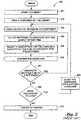
cabinets 100 include hardwired buttons (e.g., physically connected to a circuit assembly of the station) in order to track quantities of supplies within the station. For example, thecabinet 100 includes areturn button 102 and atake button 104, indicating to the cabinet'scomputer system 106 the removal or addition, respectively, of an item from an inventory for the item in a container 110 (e.g., a shelf). Thesebuttons buttons cabinet 100. - For example, when a user wants to add a new item to the inventory housed in the
cabinet 100, it usually requires a minimum of nine steps. Specifically, as illustrated in theprocess 200 ofFIG. 2 , instep 201, a user would first need to log in to thecomputer system 106 of thecabinet 100 to place thecabinet 100 into a mode that recognizes that the user intends to load a supply of items in thecontainer 110 and assignbuttons step 202, the user opens thecontainer 110 to access the space within the container, instep 203, the user loads the supply of items in thecontainer 110, and instep 204, selects thebuttons buttons container 110. Instep 205, the user selects a description for the item and a quantity of the item (e.g., indicating the supply) to associate with thebuttons 102 and 103, and confirms the selection instep 206. Indecision step 207, if the user decides to associate another item to other buttons, theprocess 200 returns tostep 203, otherwise the user instep 208 decides whether there aremore containers 110 in thecabinet 100 to load with a supply of another item. If there are more containers to load with a supply of another item, theprocess 200 proceeds tostep 209, in which the current container is closed, and another container that is to be loaded with the supply of the other item is opened, and then theprocess 200 returns tostep 203. Otherwise, if there are no more containers to load with a supply of another item, the process moves tofinal step 210, in which the user logs out of thecomputer system 106 of thecabinet 100. - By way of another example, when a user wants to reorganize items housed in a container in a cabinet, or add a different item to a fully stocked cabinet, it usually requires a minimum of fourteen steps that include requiring a user to disassociate an item from a pair of buttons and then re-associate the item with another pair of buttons. Specifically, as illustrated in the
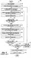
process 300 ofFIG. 3 , instep 301, a user would first need to log in to thecomputer system 106 of thecabinet 100 to place thecabinet 100 into a mode that recognizes that the user intends to reorganize items in thecontainer 110 and reassigndifferent buttons step 302, the user opens thecontainer 110 to access the space within the container, instep 303, the user unloads the supply of items from a location in thecontainer 110, instep 304, selects thebuttons 102 and 103 to disassociate from the supply of the item in thecontainer 110, and instep 305, confirms the selection. Indecision step 306, if the user wants to disassociate another item in thecontainer 110 from buttons, theprocess 300 returns tostep 304, otherwise the process proceeds tostep 307. - In
step 305, the user reloads the items unloaded instep 303 to a new location in thecontainer 110, and instep 308 selects a new pair of buttons (associated with the new location) for thesame container 110 to associate with the supply of the item. Instep 309, the user selects a description for the item and a quantity of the item (e.g., indicating the supply) to associate with the new pair ofbuttons 102 and 103, and confirms the selection instep 310. Indecision step 311, if the user decides that no other items need to be associated with a new pair of buttons (i.e., no other items were selected to be reorganized in steps 303-306), theprocess 300 proceeds todecision step 312, otherwise theprocess 300 returns tostep 308. Indecision step 312, if the user decides to load (e.g., reorganize) items in another container, then instep 313 the user closes thecurrent container 110 and opens another container, and then theprocess 300 returns tostep 303, otherwise, if the user decides not to load (e.g., reorganize) items in another container, theprocess 300 proceeds to step 314 in which the currentopen container 110 is closed, and then instep 315, the user logs out of thecomputer system 106 of thecabinet 100. - Additionally, adding new stock to the
cabinet 100 is a distinct process from restocking or reorganizing thecabinet 100 when such stock exceeds space provided in thecabinet 100. Specifically, a user performing a restock of an item has to establish a button association with the item prior to restocking the item in thecabinet 100. On the other hand, if the user wants to add a new item to the cabinet, the user must use a completely separate process - Consequently,
current cabinets 100 are difficult to reorganize, causing inefficiencies in both cabinet space utilization and responsiveness to changes in inventory quantity and selection. Inventory in acontainer 110 is rarely static as a new supply of items takes the place of other supplies over time, and inventory optimization efforts cause the required container space for each item to change. In these cases, replacing one item requires the reorganization of many items on the shelves, making theprocess 300 longer. As illustrated above, for each movement of an item, the user must remove the association of the item to its buttons and re-associate the item to another set of buttons. Even the allocation of additional space in a container for more stock of one item can cause the user to perform re-associations for several items displaced by reorganization. For example, it is not unusual for a user to have to move multiple items to accommodate a single new item or an increase in stock for an item. Consequently, reconfiguration and optimization of container space often takes several days. - As a simple example, assume container 1 currently contains gloves and container 2 currently contains bandages. If it is desired to switch these items so that container 1 contains bandages and container 2 contains gloves, the cumbersome processes described above would have to be followed, due to the hardwired and permanent nature of the take and return buttons and the current methodology.
- Unfortunately, such reconfiguration and/or optimization, such as the steps of
processes cabinet 100, rendering the cabinet unavailable to dispense medications to other users during such reconfiguration. For example, a pharmacy technician is often responsible to load 200 or reorganize 300 supplies in acabinet 100, thereby effectively taking thecabinet 100 offline while nurses and other healthcare professionals who desire to use thecabinet 100 to dispense medications must wait. This causes undue delay in using thecabinets 100, especially in a hospital setting. In many cases, hospitals attempt to avoid this concern by leaving spaces in acabinet 100 open or avoid reconfiguring thecabinet 100 altogether. US 7463947 B1 relates to a system for controlling and tracking medical items. The system includes a plurality of medical item storage cabinets. Each cabinet includes a plurality of doors. The doors control access to shelves and support modules. Shelves and support modules include user interfaces. Authorized users desiring to take medical items from storage locations in cabinets for use in treating patients are enabled to provide inputs through a display terminal adjacent to cabinets and/or interfaces to indicate the taking of medical items. Storage cabinets include visual indicators so that users may be guided to find a selected medical item for which information is input at an associated display terminal. Alternatively, authorized users gain access to the interior of the cabinet and indicate through appropriate inputs through interfaces on the shelves the types and quantities of items being taken.US 2004/207512 A1 relates to a pick/put to display (PTD) device. The PTD device includes an image display that allows the PTD device to display images related to a product, such as a picture of the product or an instructional video. By having the capability to display images of the product, the PTD device is able to reduce the risk that the wrong product will be picked or placed in a storage location. The image display further allows the PTD device to display arrows that can point in a multitude of directions. With the capability of having arrows point in numerous directions, a single PTD device is able to service multiple storage locations, thereby reducing the number of PTD devices needed. The PTD device is further capable of downloading and playing sound files for a product so that audio instructions or alerts can be played.- Embodiments of the supply cabinet disclosed herein, which has particular use as a medication cabinet, provide mobile (e.g., wireless) terminals that can be quickly moved from one container in a cabinet to another container, and quickly associated and/or disassociated with a supply of items in the container. The mobile terminals are configured to transmit information indicating changes in quantity of the supply of the items, and can assist the cabinet's controller in determining the location of the items.
- According to certain embodiments of the present disclosure, a system for tracking the quantity of an item is provided. The system includes a portable terminal, a client, and a cabinet. The portable terminal is placed inside a first container together with the quantity of the item. The portable terminal is configured to provide an actuation indication in response to a change in the quantity of the item in the first container. The portable terminal includes a unique identifier associated with the portable terminal, an input device configured to be actuated to indicate the change in the quantity of the item in the first container, and a transceiver configured to transmit the actuation indication to the client. The client is configured to receive the actuation indication from the portable terminal with a transceiver and to update the quantity of the item based on an association information stored in a memory of the client when the item is packaged for delivery, the association information comprising the unique identifier to associate the portable terminal with the item. The cabinet includes the first container configured to store the item, and a controller configured to change a value indicating a quantity of the item based on the information transmitted from the client. The controller is further configured to update a location record of the item associated with the portable terminal when the portable terminal is moved from the first container to a second container.
- According to certain aspects of the present disclosure, a method for tracking the quantity of an item is disclosed. The method includes receiving an actuation indication from a portable terminal placed inside a first container in a cabinet. The method also includes associating, in a remote client, the acutation indication with a change in the quantity of the item in the first container based on an association information stored in a memory of the client when the item is packaged for delivery prior to storage in the first container, the association information associating the portable terminal with the item using a unique identifier associated with the portable terminal, receiving a second actuation indication from the portable terminal placed inside a second container in the cabinet, and updating, in the remote client, the quantity of the item and a location record of the item associated with the portable terminal from the first container to the second container in response to the second actuation indication.
- The accompanying drawings, which are incorporated in and constitute a part of this disclosure, illustrate various embodiments and aspects of the present invention. In the drawings:
FIG. 1 illustrates a medication dispensing cabinet according to the prior art.FIG. 2 illustrates a process for loading a supply of an item in the cabinet ofFIG. 1 , according to the prior art.FIG. 3 illustrates a process for reorganizing a supply of items in the cabinet ofFIG. 1 , according to the prior art.FIG. 4A illustrates a terminal and an association station according to certain embodiments.FIG. 4B illustrates a rear-view of the terminal ofFIG. 4A in the direction of arrow IV fromFIG. 4A .FIG. 5 illustrates a dispensing station including two terminals and the association station ofFIGS. 4A-4B , according to certain embodiments.FIG. 6 illustrates a process for associating a supply of items with the terminal ofFIG. 4A , according to certain embodiments.FIG. 7 illustrates a process for loading a supply of items in the dispensing station ofFIG. 5 , according to certain embodiments.FIG. 8 illustrates a process for reorganizing a supply of items in the dispensing station ofFIG. 5 , according to certain embodiments.FIG. 9 illustrates a process for adding a new supply of items to the dispensing station ofFIG. 4A , according to certain embodiments.- In the following detailed description, numerous specific details are set forth to provide a full understanding of the present disclosure. It will be obvious, however, to one ordinarily skilled in the art that the embodiments of the present disclosure may be practiced without some of these specific details. In other instances, well-known structures and techniques have not been shown in detail to avoid obscuring the disclosure. Furthermore, although the exemplary embodiments discussed herein refer to medical supply cabinets, the systems and methods disclosed herein are applicable to all types of supply cabinets.
- In the following, parts of the description and drawings referring to embodiments which are not covered by the claims are not presented as embodiments of the invention, but as examples useful for understanding the invention.
FIG. 4A illustrates a terminal 410 (or "remote terminal" or "mobile terminal" or "button pair") and an association station 430 (or "client") according to certain embodiments. The terminal 410 is a mobile (e.g., wireless) terminal that can be quickly moved from one container in a cabinet to another container, and quickly associated and/or disassociated with a supply of items in the cabinet. The terminal 410 is detachable (e.g., not hardwired or permanently mounted), and readily removable and attachable to a cabinet as discussed below. The terminal 410 is configured to transmit information indicating a change in quantity of the supply of an item, and can assist in determining the location of the item.- The terminal 410 includes a unique identifier (not illustrated) associated with the terminal 410. The unique identifier can be, for example, an address, a bar code, or a radio frequency identification (RFID) tag. By having a unique identifier, the terminal 410 can distinguish itself from another terminal having another, different unique identifier.
- The terminal 410 also includes one or several input devices, illustrated as
buttons FIG. 4A , configured to be actuated to indicate a change in the quantity of an associated item. For example, in the illustrated embodiment, the "return"button 412 can be pressed by a user in order to indicate a decrease (e.g., by one) in the supply of the item, while the "take"button 414 can be pressed by the user in order to indicate an increase (e.g., by one) in the supply of the item. In certain embodiments, there may be only one input device configured to indicate a change in quantity of the item. In certain embodiments, there may be additional input devices associated with other actions, such as whether the terminal 410 is currently being used, to synchronize the terminal 410 with theassociation station 430, etc. Further, the actuation is not manual in certain embodiments, but is by other methods, such as by RFID recognition of placement or removal of an RFID tagged item. - An indication of the actuation (e.g., use) of the
input devices return button 412 and an LED for thetake button 414. By providing an indication of the actuation of theinput devices transceiver 440 can connected to or otherwise include, for example, a central processing unit or computer configured to receive, store, and transmit information to a remote location, such as to theassociation station 430. FIG. 4B illustrates a rear-view of theterminal 410 ofFIG. 4A in the direction of arrow IV fromFIG. 4A , according to certain embodiments. As illustrated, the terminal 410 includes mountingbrackets 424 configured to couple the terminal 410 to another object, such as a dispensing cabinet. In certain embodiments, other types of mountingbrackets 424 can be used, such as fasteners, couplers, magnets, etc. The terminal 410 also includes a mountingsensor 422 in certain embodiments. The mountingsensor 422 is configured to determine whether the terminal 410 is in use, such as by determining whether the terminal 410 is mounted to an object, such as the wall of a cabinet, or is being moved. In such cases, the mountingsensor 422 can be a proximity sensor or a contact sensor. The terminal 410 can be programmed to determine it is not in use if the mountingsensor 422 indicates the terminal 410 is not mounted, whereby the terminal 410 can decide to not transmit information from its transceiver and/or enter a power down mode. In certain embodiments, other actions may be taken by the terminal 410 if the mountingsensor 422 determines the terminal 410 is not in use. In certain embodiments, the terminal 410 can contain contact points through which the terminal 410 can communicate and receive power, such as by docking to embodiments of the cabinet discussed below. In certain embodiments, the terminal 410 contains its own power source (e.g., rechargeable batteries).Association station 430 is configured to associate theportable terminal 410 with the item based on the unique identifier. Theassociation station 430 can be, for example, a processing system that includes an input device (e.g., keyboard), output device (e.g., display), a processor, and memory. Theassociation station 430 includes atransceiver 450 configured to receive the information indicating the change in the quantity of the item from the terminal 410, and transmit the information to the dispensingstation 500 illustrated inFIG. 5 .- Specifically,
FIG. 5 illustrates a dispensing station 500 (or "medication cabinet" or "inventory-tracking device") including twoterminals association station 430 ofFIGS. 4A-4B , according to certain embodiments. The dispensingstation 500 includes acontroller 506 that is configured to control access tocontainers station 500, and track the quantity and location of the items in thecontainers Association station 430 is configured to associate each ofterminals terminals association station 430 is separate from thecontroller 506 in order to provide the inventory tracking features of themobile terminal 410 as discussed herein. In certain embodiments, theassociation station 430 can be included in or a part of the dispensingcabinet 500, and may be accessible through thecontroller 506 of the dispensingcabinet 500. However, it should be understood that in such embodiments, the terminal 410a and 410b remain mobile and are not hardwired to the dispensingstation 500. - The
association station 430 is further configured to communicate with acontroller 506 included in the dispensingstation 500, such as to indicate a change in the quantity of a supply of items and a location of the items. For example, if the take button of terminal 410a is pressed by a user, then terminal 410a transmits information toassociation station 430 indicating its take button has been pressed. Theassociation station 430, which has associated a supply of items, for example, item A, with terminal 410a, receives the information from terminal 410a, and then transmits information to thecontroller 506 indicating item A has decreased by one. Thecontroller 506 receives the information from theassociation station 430, and then updates its supply record of item A, decreasing the value by one. Furthermore, if only one container,container 510, of theassociation station 430 is open, then thecontroller 506 can also determine that item A associated with terminal 410a is incontainer 510, because no other containers of the dispensingstation 500 are currently accessible. In certain embodiments not falling under the claims,controller 506 interacts directly with terminal 410a (e.g., without association station 430), for example, to indicate a change in the quantity of a supply of items and a location of the items. - By way of another example, if initially both
containers container 510 tocontainer 520 andcontainer 510 is closed, and finally the take button ofterminal 410b is pressed by a user, then thecontroller 506 can both (1) update its supply record of the item associated withterminal 410b, decreasing the value by one, and (2) update its location record of the item associated with terminal 410b to indicate the item's supply is now located incontainer 520, because no other containers of the dispensingstation 500 are currently accessible other thancontainer 520. - Unlike the prior art, in which an item is both associated with
buttons cabinet 100 in the same process (as illustrated inFIG. 2 ), resulting in significant downtime of thecabinet 100 on a hospital floor, the processes disclosed herein advantageously separate association of items with a terminal 410 (as described inFIG. 6 ) from loading the items and the terminal 410 in a dispensing station 500 (as described inFIG. 7 ), so that the association of the items with the terminal 410 can take place away from the hospital floor, reducing downtime of the dispensingstation 500 to only the loading of items and the terminal into the dispensingstation 500. In order to further increase efficiency, the terminal 410 may be associated with a supply of items when the items are packaged for delivery, such that a properly configuredterminal 410 arrives each supply of items. FIG. 6 illustrates aprocess 600 for associating a supply of items with theterminal 410 ofFIG. 4A , according to certain examples useful for understanding the invention. Theprocess 600 can occur away from the location of the dispensingstation 500 so that the dispensingstation 500 can remain available to dispense medication and other items to users. Theprocess 600 may be performed as many times as necessary to associate the required number ofterminals 410 for supplies of items. The configuration created by theprocess 600, as well as theprocesses FIGS. 7-9 may be stored in the terminal 410, theassociation station 430, the dispensingstation 500, or another location.- The
process 600 begins instep 601, where a user logs in to theassociation station 430, such as by providing authentication information. The authentication information can include a biometric identifier, a name and password, or other form of user identification known to those of skill in the art. Instep 602, the user selects a terminal 410, and instep 603 selects a description of an item (e.g., "Atenolol 20mg") and a quantity of the item (e.g., "50") to associate with the terminal 410. Instep 604, the user confirms the selection ofstep 603. Indecision step 605, if another terminal is to be associated with the supply of another item, theprocess 600 returns to step 602, otherwise theprocess 600 ends. - Having set forth in
FIG. 6 aprocess 600 for associating a supply of items with theterminal 410 ofFIG. 4A , an example will now be presented using theprocess 600 ofFIG. 6 wherein a pharmacy technician associates the items Atenolol and Diazepam with theterminals FIG. 5 . Theprocess 600 begins instep 601, where the pharmacy technician logs in to theassociation station 430 using his user identification and password. Instep 602, the pharmacy technician selects the terminal 410a in acontainer 510, and instep 603 enters the description "Atenolol 20mg" and quantity "50" to associate with the terminal 410a. Instep 604, the pharmacy technician confirms the selection ofstep 603. Indecision step 605, the pharmacy technician chooses to associate another terminal with the supply of another item, and theprocess 600 returns to step 602. Returning to step 602, the pharmacy technician selects the terminal 410b in the container 510 (ofFIG. 5 ), and instep 603 enters the description "Diazepam 10mg" and quantity "50" to associate with the terminal 410b. Instep 604, the pharmacy technician confirms the selection ofstep 603. Indecision step 605, the pharmacy technician chooses not to associate another terminal with the supply of another item, and theprocess 600 ends. FIG. 7 illustrates aprocess 700 for loading a supply of items in the dispensingstation 500 ofFIG. 5 with a terminal 410 configured using theprocess 600 ofFIG. 6 , according to certain examples useful for understanding the invention. Theprocess 700 begins instep 701, where a user logs in to the dispensingstation 500, such as by providing authentication information. Instep 702, the user opens acontainer 510 of the dispensingstation 500, and then instep 703 loads a supply of an item into thecontainer 510. Instep 704, the terminal 410 configured inprocess 600 above for the supply of the item in thecontainer 510 is placed near the supply of the item in thecontainer 510, such as in front of the supply. Thecontainer 510 is closed instep 705. If indecision step 706 there are more containers to load, theprocess 700 returns to step 702, otherwise the user logs out of the dispensingstation 500 instep 707 and theprocess 700 ends. From the standpoint of a dispensingstation 500 user, theprocess 700 takes six steps, in comparison with theprior art process 200 illustrated inFIG. 2 , which takes 9 steps. If the dispensingstation 500 stores an average of 70 items, theprocess 700 disclosed herein saves 140 steps (saving 2 steps for each of 70 items), thereby providing an improvement in efficiency and time for the user.- Having set forth in
FIG. 7 aprocess 700 for loading a supply of items in the dispensingstation 500 with a terminal 410 configured using theprocess 600 ofFIG. 6 , an example will now be presented using theprocess 700 ofFIG. 7 wherein a pharmacy technician loads the items Atenolol and Diazepam, and theterminals station 500. Theprocess 700 begins instep 701, where the pharmacy technician logs in to the dispensingstation 500 using his fingerprint. The dispensingstation 500 is thereby placed into a mode to recognize that the pharmacy technician intends to load or reorganize items in the dispensingstation 500. Instep 702, the pharmacy technician opens thecontainer 510 of the dispensingstation 500, and then instep 703 loads a supply of 50 Atenolol (50 mg/each) into thecontainer 510. At this step, other containers in the dispensingstation 500 may lock so that the dispensingstation 500 can identify that anyterminals 410 placed in the dispensingstation 500 are in the openedcontainer 510. Instep 704, the pharmacy technician mounts the terminal 410a (configured inprocess 600 above for the supply of Atenolol) near the supply of Atenolol in a configuration that activates the mountingsensor 422 of the terminal 410a. Thecontainer 510 is closed instep 705. Indecision step 706, the pharmacy technician decides there are more containers to load, and theprocess 700 returns to step 702. Returning to step 702, the pharmacy technician again opens thecontainer 510 of the dispensingstation 500, and then instep 703 loads a supply of 50 Diazepam (10 mg/each) into thecontainer 510. Instep 704, the pharmacy technician mounts the terminal 410b (configured inprocess 600 above for the supply of Diazepam) near the supply of Diazepam in a configuration that activates the mountingsensor 422 of the terminal 410b. Thecontainer 510 is closed instep 705. Indecision step 706, the pharmacy technician decides there are no more containers to load, the pharmacy technician logs out of the dispensingstation 500 instep 707, and theprocess 700 ends. FIG. 8 illustrates aprocess 800 for reorganizing a supply of items in the dispensingstation 500 ofFIG. 5 , according to certain examples useful for understanding the invention. Theprocess 800 begins instep 801, where a user logs in to the dispensingstation 500, such as by providing authentication information. Instep 802, the user opens acontainer 510 of the dispensingstation 500, and then instep 803 reorganizes the locations of items in thecontainer 510. Instep 804, the user moves theterminals 410 associated with the items according to the reorganized location of the items, so that each terminal 410 associated with a supply of an item is proximal to the supply of the item. Thecontainer 510 is closed instep 805. If indecision step 806 there are more containers to reorganize, theprocess 800 returns to step 802, otherwise the user logs out of the dispensingstation 500 instep 807 and theprocess 800 ends.- Unlike the
prior art process 300 ofFIG. 3 , in which the user was required to disassociate a pair of buttons with an item and then re-associate a new pair of buttons with the item, in theprocess 800 disclosed herein the user simply needs to move the terminal 410 along with the item. The number of steps inprocess 800 is reduced by half (7 steps inprocess 800 versus 14 steps in process 300) compared to theprior art process 300 for reorganizing a supply of items. - Having set forth in
FIG. 8 aprocess 800 for reorganizing a supply of items in the dispensingstation 500 ofFIG. 5 , an example will now be presented using theprocess 800 ofFIG. 8 wherein a pharmacy technician reorganizes the items Atenolol and Diazepam, and their associatedterminals station 500. Theprocess 800 begins instep 801, where the pharmacy technician logs in to the dispensingstation 500 using his fingerprint. The dispensingstation 500 is thereby placed into a mode to recognize that the pharmacy technician intends to load or reorganize items in the dispensingstation 500. Instep 802, the pharmacy technician opens thecontainer 510 of the dispensingstation 500 containing the supplies of Atenolol and Diazepam, and then instep 803 reorganizes thecontainer 510 by removing the supply of Diazepam from thecontainer 510. Atstep 802, other containers in the dispensingstation 500 may lock so that the dispensingstation 500 can identify that any terminals reorganized in the dispensingstation 500 are in the openedcontainer 510. Instep 804, the pharmacy technician removes the terminal 410b associated with the supply of Diazepam. Thecontainer 510 is closed instep 805. Indecision step 806, the pharmacy technician decides there are more containers to reorganize because he wants to add the supply of Diazepam to another container 520 (illustrated inFIG. 5 ) in the dispensingstation 500, so theprocess 800 returns to step 802. Returning to step 802, the pharmacy technician opens theother container 520 of the dispensingstation 500, and instep 803 reorganizes thecontainer 520 by loading the supply of Diazepam into thecontainer 520. Instep 804, the pharmacy technician mounts the terminal 410b associated with the supply of Diazepam into thecontainer 520 in a configuration that activates the mountingsensor 422 of the terminal 410b. The pharmacy technician may optionally press both thetake button 414 and thereturn button 412 of the terminal 410b together to indicate to thecontroller 506 of the dispensing station (as discussed above) that the supply of Diazepam is now located incontainer 520, notcontainer 510. Thecontainer 520 is closed instep 805. Indecision step 806, the pharmacy technician decides there are no more containers to reorganize, the pharmacy technician logs out of the dispensingstation 500 instep 807, and theprocess 800 ends. FIG. 9 illustrates a process for adding a new supply of items to the dispensingstation 500 ofFIG. 5 , according to certain examples useful for understanding the invention. Theprocess 900 begins instep 901, where a user logs in to the dispensingstation 500, such as by providing authentication information. Instep 902, the user opens acontainer 510 of the dispensingstation 500, and then instep 903 reorganizes the locations of items in thecontainer 510. Instep 904, the user moves theterminals 410 associated with the items according to the reorganized location of the items, so that each terminal 410 associated with a supply of an item is proximal to the supply of the item. Instep 905, a supply for a new item is placed in theopen container 510, and aremote terminal 410 associated with the supply for the new item is placed in proximity to the supply incontainer 510. Thecontainer 510 is closed instep 906. If indecision step 906 there are more containers to reorganize or to which new items are to be added, theprocess 900 returns to step 902, otherwise the user logs out of the dispensingstation 500 instep 908 and theprocess 900 ends. As can be seen from the disclosedprocess 900 for adding a new item to acontainer 510, only one new step,step 905, is added as compared to the disclosedprocess 800 for reorganizing items in acontainer 510.- Having set forth in
FIG. 9 aprocess 900 for adding a new supply of items to the dispensingstation 500 ofFIG. 5 , an example will now be presented using theprocess 900 ofFIG. 9 wherein a pharmacy technician adds the item Acebutolol and an associated terminal 410 in the dispensingstation 500. Theprocess 900 begins instep 901, where the pharmacy technician logs in to the dispensingstation 500 using his fingerprint. The dispensingstation 500 is thereby placed into a mode to recognize that the pharmacy technician intends to load or reorganize items in the dispensingstation 500. Instep 902, the pharmacy technician opens thecontainer 510 of the dispensingstation 500, and then instep 903 reorganizes the locations of items in thecontainer 510 to create space for the new item, Acebutolol. Atstep 902, other containers in the dispensingstation 500 may lock so that the dispensingstation 500 can identify that any terminals reorganized in the dispensingstation 500 are in the openedcontainer 510. Instep 904, the pharmacy technician moves theterminals 410 associated with the items according to the reorganized location of the items, so that each terminal 410 associated with a supply of an item is proximal to the supply of the item in a configuration that activates each mountingsensor 422 of theterminals 410. Instep 905, a supply for Acebutolol is placed in theopen container 510, and aremote terminal 410 associated with the supply of Acebutolol is placed near the supply in thecontainer 510. Thecontainer 510 is closed instep 906. The pharmacy technician decides there are no more containers to reorganize indecision step 906, the pharmacy technician logs out of the dispensingstation 500 instep 908, and theprocess 900 ends. - The embodiments of the present disclosure provide a supply cabinet that includes mobile (e.g., wireless) terminals that can be quickly moved from one container in the cabinet to another container, and quickly associated and/or disassociated with a supply of items in the container. The mobile terminals are configured to transmit information indicating changes in quantity of the supply of the items, and can assist the cabinet's controller in determining the location of the items.
Claims (14)
- A system for tracking the quantity of an item comprising:a portable terminal (410) placed inside a first container (510) together with the quantity of the item, the portable terminal configured to provide an actuation indication in response to a change in the quantity of the item in the first container (510), and comprising:a unique identifier associated with the portable terminal (410);an input device (412) configured to be actuated to indicate the change in the quantity of the item in the first container (510); anda transceiver (440) configured to transmit the actuation indication to a client (430);the client (430), configured to receive the actuation indication from the portable terminal (410) with a transceiver (450) and to update the quantity of the item based on an association information stored in a memory of the client (430) when the item is packaged for delivery, the association information comprising the unique identifier to associate the portable terminal with the item; anda cabinet (500) comprising:the first container (510) configured to store the item; anda controller (506) configured to change a value indicating a quantity of the item based on the information transmitted from the client (430), wherein the controller is further configured to update a location record of the item associated with the portable terminal when the portable terminal (410) is moved from the first container (510) to a second container (520).
- The system of Claim 1, wherein the portable terminal (410) further comprises an indicator configured to indicate the actuation of the input device to a user.
- The system of Claim 1, the client (430) further comprising a user interface configured to receive instructions to disassociate the portable terminal (410) with the item, and to associate the portable terminal (410) with another item based on the unique identifier and input from a user.
- The system of Claim 1, wherein the transceiver (450) of the client (430) is configured to determine whether the first container (510) includes the item.
- The system of Claim 1, wherein the transceiver (450) of the client (430) is configured to receive an actuation indication from a plurality of portable terminals (410).
- The system of Claim 1, wherein the portable terminal (410) further comprises a sensor configured to determine if the portable terminal (410) is currently in use.
- The system of Claim 1, wherein the portable terminal (410) further comprises an attachment module configured to couple the portable terminal (410) to a portion of the first container (510) that includes the item.
- The system of Claim 1, wherein the input device (412) is a push button.
- The system of Claim 1, wherein the input device (412) includes a first button and a second button, the first button configured to indicate an increase in the quantity of the item, and the second button configured to indicate a decrease in the quantity of the item.
- A method for tracking the quantity of an item comprising:receiving an actuation indication from a portable terminal (410) placed inside a first container (510) in a cabinet (500);associating, in a remote client (430), the actuation indication with a change in the quantity of the item in the first container (510) based on an association information stored in a memory of the client (430) when the item is packaged for delivery prior to storage in the first container (510), the association information associating the portable terminal with the item using a unique identifier associated with the portable terminal (410);receiving a second actuation indication from the portable terminal (410) placed inside a second container (520) in the cabinet (500); andupdating, in the remote client (430), the quantity of the item and a location record of the item associated with the portable terminal from the first container (510) to the second container (520) in response to the second actuation indication.
- The method of Claim 10, further comprising transmitting the actuation indication to a controller (506) configured to change a value indicating a quantity of the item based on the transmitted actuation indication, wherein the cabinet (500) comprises the controller (506).
- The method of Claim 10, wherein after receiving the actuation indication from the portable terminal (410) at the second container (520), the method further comprises determining if the item is in the first container (510), or in the second container (520) in the cabinet (500).
- The method of Claim 12, wherein the determining is based on which one of the first container (510) and the second container (520) is accessible.
- The method of Claim 10, further comprising:receiving a request to associate the portable terminal (410) with another item in the cabinet (500);associating the portable terminal (410) with the other item in the cabinet (500) based on the request and the unique identifier;receiving information from the portable terminal (410) indicating another change in quantity; andassociating the information indicating the other change in quantity with the other item based on the unique identifier.
Applications Claiming Priority (2)
| Application Number | Priority Date | Filing Date | Title |
|---|---|---|---|
| US12/503,012US10657488B2 (en) | 2009-07-14 | 2009-07-14 | Portable inventory tracking system |
| PCT/US2010/041820WO2011008751A2 (en) | 2009-07-14 | 2010-07-13 | Portable inventory tracking system |
Publications (3)
| Publication Number | Publication Date |
|---|---|
| EP2454709A2 EP2454709A2 (en) | 2012-05-23 |
| EP2454709A4 EP2454709A4 (en) | 2014-08-06 |
| EP2454709B1true EP2454709B1 (en) | 2021-04-14 |
Family
ID=43450132
Family Applications (1)
| Application Number | Title | Priority Date | Filing Date |
|---|---|---|---|
| EP10736923.3AActiveEP2454709B1 (en) | 2009-07-14 | 2010-07-13 | Portable inventory tracking system |
Country Status (10)
| Country | Link |
|---|---|
| US (4) | US10657488B2 (en) |
| EP (1) | EP2454709B1 (en) |
| JP (1) | JP2012533490A (en) |
| KR (3) | KR20170086698A (en) |
| CN (1) | CN102473255B (en) |
| AU (2) | AU2010273548A1 (en) |
| CA (1) | CA2767334C (en) |
| MX (1) | MX2012000394A (en) |
| RU (1) | RU2012100245A (en) |
| WO (1) | WO2011008751A2 (en) |
Families Citing this family (15)
| Publication number | Priority date | Publication date | Assignee | Title |
|---|---|---|---|---|
| US10089443B2 (en) | 2012-05-15 | 2018-10-02 | Baxter International Inc. | Home medical device systems and methods for therapy prescription and tracking, servicing and inventory |
| US8746908B2 (en) | 2010-01-27 | 2014-06-10 | Automed Technologies, Inc. | Medical supply cabinet with lighting features |
| CN102682374A (en)* | 2012-05-22 | 2012-09-19 | 苏州奇可思信息科技有限公司 | Product stock management system |
| JP6321006B2 (en) | 2012-08-24 | 2018-05-09 | パーセプティメッド インコーポレイテッドPerceptimed, Inc. | System for finding packages |
| WO2016062911A1 (en)* | 2014-10-23 | 2016-04-28 | Servicio Andaluz De Salud | Portable identification element, system, and method for dispensing products |
| JP5858305B1 (en)* | 2014-10-24 | 2016-02-10 | アクアエンタープライズ株式会社 | Mobile terminal, mobile terminal program, checkpoint management system, and checkpoint management method |
| US9886605B2 (en) | 2015-09-14 | 2018-02-06 | Cubex Llc | Inventory management system |
| US20170357933A1 (en)* | 2016-06-08 | 2017-12-14 | The Procter & Gamble Company | Methods and Systems for Distributing Goods |
| US20180121866A1 (en)* | 2016-10-27 | 2018-05-03 | Cubex Llc | Inventory management system using individual modules |
| CA3068306A1 (en) | 2017-06-28 | 2019-01-03 | Perceptimed, Inc. | Inventory management |
| US11643228B1 (en)* | 2019-09-24 | 2023-05-09 | Amazon Technologies, Inc. | Modular containerization systems and methods |
| CN111459036B (en)* | 2020-02-24 | 2021-11-16 | 珠海格力电器股份有限公司 | Intelligent cabinet control method and device, electronic equipment and storage medium |
| WO2021188775A1 (en) | 2020-03-18 | 2021-09-23 | Duke Manufacturing Co. | Networked food preparation apparatus |
| US12318035B2 (en) | 2020-03-18 | 2025-06-03 | Duke Manufacturing Co. | Networked food preparation apparatus |
| US12223383B2 (en) | 2020-03-18 | 2025-02-11 | Duke Manufacturing Co. | Smart food pan system |
Family Cites Families (40)
| Publication number | Priority date | Publication date | Assignee | Title |
|---|---|---|---|---|
| US6801877B2 (en)* | 1993-11-12 | 2004-10-05 | Entek Ird International Corporation | Portable, self-contained data collection systems and methods |
| US5905653A (en) | 1994-07-14 | 1999-05-18 | Omnicell Technologies, Inc. | Methods and devices for dispensing pharmaceutical and medical supply items |
| IL117952A0 (en) | 1996-04-18 | 1996-08-04 | Eldat Communication Ltd | Product identification and counting system |
| FR2751111B1 (en)* | 1996-07-10 | 1998-10-09 | Axytrans | SYSTEM FOR SECURE TRANSPORT OF OBJECTS IN TAMPER-PROOF CONTAINERS OF WHICH AT LEAST ONE DESTINATION STATION IS MOBILE AND TRANSPORTABLE |
| US6223163B1 (en)* | 1997-03-21 | 2001-04-24 | Walker Digital, Llc | Method and apparatus for controlling offers that are provided at a point-of-sale terminal |
| GB9710522D0 (en) | 1997-05-23 | 1997-07-16 | Rolls Royce Plc | Control system |
| US6011999A (en) | 1997-12-05 | 2000-01-04 | Omnicell Technologies, Inc. | Apparatus for controlled dispensing of pharmaceutical and medical supplies |
| US6151536A (en) | 1998-09-28 | 2000-11-21 | Omnicell.Com | Dispensing system and methods |
| US7463947B1 (en) | 2000-05-05 | 2008-12-09 | Automed Technologies, Inc. | Medical item storage cabinet and method |
| US7072855B1 (en) | 2000-07-24 | 2006-07-04 | Omnicell, Inc. | Systems and methods for purchasing, invoicing and distributing items |
| US7212098B1 (en)* | 2000-09-21 | 2007-05-01 | Myspace, Llc | Portable security container |
| US7084738B2 (en) | 2000-12-11 | 2006-08-01 | Asap Automation, Llc | Inventory system with image display |
| US6993501B1 (en)* | 2001-03-15 | 2006-01-31 | Dispensesource, Inc. | Method and system of communication for automated inventory systems |
| KR20030052675A (en) | 2001-12-21 | 2003-06-27 | 주식회사 디앤에스 테크놀로지 | Home Delivery Freight Deposit Management System |
| US20030117281A1 (en)* | 2001-12-21 | 2003-06-26 | Timur Sriharto | Dynamic control containment unit |
| EP1391579B1 (en)* | 2002-08-13 | 2015-01-21 | CargoGuard GmbH | Portable security container |
| US6959862B2 (en) | 2002-11-25 | 2005-11-01 | Yoram Neumark | Inventory control and identification method |
| US7052097B2 (en)* | 2002-12-06 | 2006-05-30 | Mckesson Automation, Inc. | High capacity drawer with mechanical indicator for a dispensing device |
| DE10324486A1 (en)* | 2003-05-30 | 2004-12-16 | Degussa Ag | Use of urea derivatives as accelerators for epoxy resins |
| KR100807921B1 (en)* | 2003-09-08 | 2008-02-27 | 주식회사 엑스-큐브 | Receipt and / or delivery depository system, its reservation method and billing method |
| EP1690193A4 (en)* | 2003-11-25 | 2008-05-21 | Cordis Corp | Medical device radiofrequency identification system and method |
| CN1781423A (en) | 2004-06-21 | 2006-06-07 | 美国森科皮奇有限公司 | Dispensing system for integrated household product inventory |
| JP2006021891A (en) | 2004-07-08 | 2006-01-26 | Toshiba Tec Corp | Case with wireless tag for storing goods |
| US7348884B2 (en) | 2004-07-29 | 2008-03-25 | Omnicell, Inc. | RFID cabinet |
| JP4484619B2 (en)* | 2004-07-30 | 2010-06-16 | 株式会社Access | Method, terminal device and program for image output by automatic recognition of table image |
| US7146247B2 (en) | 2004-11-24 | 2006-12-05 | Cerner Innovation, Inc. | Computerized method and system for loading and/or unloading a tray using laser scanning technology |
| US7421367B2 (en) | 2004-12-21 | 2008-09-02 | Nye Pamela F | Handheld computing device for performing multitasks in healthcare applications |
| US20060173750A1 (en)* | 2004-12-30 | 2006-08-03 | Naley Martin R | System and method for controlling access to a local inventory storage system via a remote e-commerce application |
| US20060232412A1 (en)* | 2005-04-15 | 2006-10-19 | Jorge Tabacman & Associates P/L | Intelligent reader system and method for identifying and tracking goods and materials transported in pallets, including but not limited to scaffolding materials |
| US7639136B1 (en)* | 2005-05-13 | 2009-12-29 | WaveMark, Inc. | RFID medical supplies consumption monitoring system and method |
| IL170755A (en)* | 2005-09-08 | 2010-06-16 | John Mcfarland | Dispensing system for tools |
| CA2565408C (en) | 2005-10-25 | 2013-01-08 | Mckesson Automation Systems, Inc. | Adaptive interface for product dispensing systems |
| TW200723153A (en) | 2005-11-18 | 2007-06-16 | Murata Machinery Ltd | Storage system |
| US7630791B2 (en) | 2005-12-09 | 2009-12-08 | CareFusion 303 Inc. | System and method for storing items and tracking item usage |
| JP2008094534A (en)* | 2006-10-11 | 2008-04-24 | Toa Holdings Inc | Picking system |
| JP2008214098A (en) | 2007-02-06 | 2008-09-18 | Sanden Corp | Inventory management system |
| US20080249899A1 (en)* | 2007-04-05 | 2008-10-09 | Nasser Gabriel G | System and Method for Inventory |
| US7518502B2 (en) | 2007-05-24 | 2009-04-14 | Smith & Nephew, Inc. | System and method for tracking surgical assets |
| JP2008299468A (en) | 2007-05-30 | 2008-12-11 | Post Cube System Co Ltd | Locker device |
| US8234008B2 (en)* | 2008-02-29 | 2012-07-31 | Carefusion 303, Inc. | Lidded drawer for single line item dispensing |
- 2009
- 2009-07-14USUS12/503,012patent/US10657488B2/enactiveActive
- 2010
- 2010-07-13KRKR1020177020057Apatent/KR20170086698A/ennot_activeCeased
- 2010-07-13EPEP10736923.3Apatent/EP2454709B1/enactiveActive
- 2010-07-13KRKR1020127001110Apatent/KR20120048561A/ennot_activeCeased
- 2010-07-13CNCN201080031687.5Apatent/CN102473255B/enactiveActive
- 2010-07-13KRKR1020187016573Apatent/KR20180069097A/ennot_activeCeased
- 2010-07-13CACA2767334Apatent/CA2767334C/enactiveActive
- 2010-07-13JPJP2012520718Apatent/JP2012533490A/enactivePending
- 2010-07-13RURU2012100245/08Apatent/RU2012100245A/ennot_activeApplication Discontinuation
- 2010-07-13AUAU2010273548Apatent/AU2010273548A1/ennot_activeAbandoned
- 2010-07-13WOPCT/US2010/041820patent/WO2011008751A2/enactiveApplication Filing
- 2010-07-13MXMX2012000394Apatent/MX2012000394A/enactiveIP Right Grant
- 2016
- 2016-08-12AUAU2016213898Apatent/AU2016213898B2/enactiveActive
- 2020
- 2020-05-05USUS16/867,493patent/US11176515B2/enactiveActive
- 2021
- 2021-11-15USUS17/527,045patent/US11568363B2/enactiveActive
- 2023
- 2023-01-30USUS18/103,431patent/US12136063B2/enactiveActive
Also Published As
| Publication number | Publication date |
|---|---|
| JP2012533490A (en) | 2012-12-27 |
| AU2016213898A1 (en) | 2016-09-01 |
| CN102473255B (en) | 2015-12-02 |
| KR20120048561A (en) | 2012-05-15 |
| EP2454709A2 (en) | 2012-05-23 |
| KR20180069097A (en) | 2018-06-22 |
| RU2012100245A (en) | 2013-08-20 |
| US20110016026A1 (en) | 2011-01-20 |
| CA2767334C (en) | 2020-12-15 |
| US20220076198A1 (en) | 2022-03-10 |
| US10657488B2 (en) | 2020-05-19 |
| MX2012000394A (en) | 2012-05-23 |
| EP2454709A4 (en) | 2014-08-06 |
| KR20170086698A (en) | 2017-07-26 |
| BR112012000331A2 (en) | 2019-09-10 |
| AU2016213898B2 (en) | 2018-04-05 |
| CA2767334A1 (en) | 2011-01-20 |
| WO2011008751A3 (en) | 2011-06-16 |
| US20200265376A1 (en) | 2020-08-20 |
| WO2011008751A2 (en) | 2011-01-20 |
| US20230169458A1 (en) | 2023-06-01 |
| US12136063B2 (en) | 2024-11-05 |
| US11568363B2 (en) | 2023-01-31 |
| CN102473255A (en) | 2012-05-23 |
| AU2010273548A1 (en) | 2012-02-02 |
| US11176515B2 (en) | 2021-11-16 |
Similar Documents
| Publication | Publication Date | Title |
|---|---|---|
| US11176515B2 (en) | Portable inventory tracking system | |
| US12102569B2 (en) | Medical technology station and method of use | |
| US9747743B2 (en) | Patient-specific medication dispensing and notification system | |
| BR112012000331B1 (en) | SYSTEM AND METHOD FOR TRACKING A QUANTITY OF A TYPE OF ITEM |
Legal Events
| Date | Code | Title | Description |
|---|---|---|---|
| PUAI | Public reference made under article 153(3) epc to a published international application that has entered the european phase | Free format text:ORIGINAL CODE: 0009012 | |
| 17P | Request for examination filed | Effective date:20120209 | |
| AK | Designated contracting states | Kind code of ref document:A2 Designated state(s):AL AT BE BG CH CY CZ DE DK EE ES FI FR GB GR HR HU IE IS IT LI LT LU LV MC MK MT NL NO PL PT RO SE SI SK SM TR | |
| DAX | Request for extension of the european patent (deleted) | ||
| A4 | Supplementary search report drawn up and despatched | Effective date:20140704 | |
| RIC1 | Information provided on ipc code assigned before grant | Ipc:G06Q 50/22 20120101ALI20140630BHEP Ipc:B65G 1/00 20060101ALI20140630BHEP Ipc:G06Q 10/08 20120101AFI20140630BHEP | |
| 17Q | First examination report despatched | Effective date:20150303 | |
| APBK | Appeal reference recorded | Free format text:ORIGINAL CODE: EPIDOSNREFNE | |
| APBN | Date of receipt of notice of appeal recorded | Free format text:ORIGINAL CODE: EPIDOSNNOA2E | |
| APBR | Date of receipt of statement of grounds of appeal recorded | Free format text:ORIGINAL CODE: EPIDOSNNOA3E | |
| APAF | Appeal reference modified | Free format text:ORIGINAL CODE: EPIDOSCREFNE | |
| APAF | Appeal reference modified | Free format text:ORIGINAL CODE: EPIDOSCREFNE | |
| APBX | Invitation to file observations in appeal sent | Free format text:ORIGINAL CODE: EPIDOSNOBA2E | |
| APBZ | Receipt of observations in appeal recorded | Free format text:ORIGINAL CODE: EPIDOSNOBA4E | |
| APBT | Appeal procedure closed | Free format text:ORIGINAL CODE: EPIDOSNNOA9E | |
| GRAP | Despatch of communication of intention to grant a patent | Free format text:ORIGINAL CODE: EPIDOSNIGR1 | |
| STAA | Information on the status of an ep patent application or granted ep patent | Free format text:STATUS: GRANT OF PATENT IS INTENDED | |
| INTG | Intention to grant announced | Effective date:20201030 | |
| GRAS | Grant fee paid | Free format text:ORIGINAL CODE: EPIDOSNIGR3 | |
| GRAA | (expected) grant | Free format text:ORIGINAL CODE: 0009210 | |
| STAA | Information on the status of an ep patent application or granted ep patent | Free format text:STATUS: THE PATENT HAS BEEN GRANTED | |
| AK | Designated contracting states | Kind code of ref document:B1 Designated state(s):AL AT BE BG CH CY CZ DE DK EE ES FI FR GB GR HR HU IE IS IT LI LT LU LV MC MK MT NL NO PL PT RO SE SI SK SM TR | |
| REG | Reference to a national code | Ref country code:GB Ref legal event code:FG4D | |
| REG | Reference to a national code | Ref country code:CH Ref legal event code:EP | |
| REG | Reference to a national code | Ref country code:DE Ref legal event code:R096 Ref document number:602010066798 Country of ref document:DE | |
| REG | Reference to a national code | Ref country code:IE Ref legal event code:FG4D | |
| REG | Reference to a national code | Ref country code:AT Ref legal event code:REF Ref document number:1383104 Country of ref document:AT Kind code of ref document:T Effective date:20210515 | |
| REG | Reference to a national code | Ref country code:LT Ref legal event code:MG9D | |
| REG | Reference to a national code | Ref country code:NL Ref legal event code:MP Effective date:20210414 | |
| PG25 | Lapsed in a contracting state [announced via postgrant information from national office to epo] | Ref country code:FI Free format text:LAPSE BECAUSE OF FAILURE TO SUBMIT A TRANSLATION OF THE DESCRIPTION OR TO PAY THE FEE WITHIN THE PRESCRIBED TIME-LIMIT Effective date:20210414 Ref country code:NL Free format text:LAPSE BECAUSE OF FAILURE TO SUBMIT A TRANSLATION OF THE DESCRIPTION OR TO PAY THE FEE WITHIN THE PRESCRIBED TIME-LIMIT Effective date:20210414 Ref country code:LT Free format text:LAPSE BECAUSE OF FAILURE TO SUBMIT A TRANSLATION OF THE DESCRIPTION OR TO PAY THE FEE WITHIN THE PRESCRIBED TIME-LIMIT Effective date:20210414 Ref country code:BG Free format text:LAPSE BECAUSE OF FAILURE TO SUBMIT A TRANSLATION OF THE DESCRIPTION OR TO PAY THE FEE WITHIN THE PRESCRIBED TIME-LIMIT Effective date:20210714 Ref country code:HR Free format text:LAPSE BECAUSE OF FAILURE TO SUBMIT A TRANSLATION OF THE DESCRIPTION OR TO PAY THE FEE WITHIN THE PRESCRIBED TIME-LIMIT Effective date:20210414 | |
| PG25 | Lapsed in a contracting state [announced via postgrant information from national office to epo] | Ref country code:IS Free format text:LAPSE BECAUSE OF FAILURE TO SUBMIT A TRANSLATION OF THE DESCRIPTION OR TO PAY THE FEE WITHIN THE PRESCRIBED TIME-LIMIT Effective date:20210814 Ref country code:GR Free format text:LAPSE BECAUSE OF FAILURE TO SUBMIT A TRANSLATION OF THE DESCRIPTION OR TO PAY THE FEE WITHIN THE PRESCRIBED TIME-LIMIT Effective date:20210715 Ref country code:LV Free format text:LAPSE BECAUSE OF FAILURE TO SUBMIT A TRANSLATION OF THE DESCRIPTION OR TO PAY THE FEE WITHIN THE PRESCRIBED TIME-LIMIT Effective date:20210414 Ref country code:SE Free format text:LAPSE BECAUSE OF FAILURE TO SUBMIT A TRANSLATION OF THE DESCRIPTION OR TO PAY THE FEE WITHIN THE PRESCRIBED TIME-LIMIT Effective date:20210414 Ref country code:NO Free format text:LAPSE BECAUSE OF FAILURE TO SUBMIT A TRANSLATION OF THE DESCRIPTION OR TO PAY THE FEE WITHIN THE PRESCRIBED TIME-LIMIT Effective date:20210714 Ref country code:PL Free format text:LAPSE BECAUSE OF FAILURE TO SUBMIT A TRANSLATION OF THE DESCRIPTION OR TO PAY THE FEE WITHIN THE PRESCRIBED TIME-LIMIT Effective date:20210414 Ref country code:PT Free format text:LAPSE BECAUSE OF FAILURE TO SUBMIT A TRANSLATION OF THE DESCRIPTION OR TO PAY THE FEE WITHIN THE PRESCRIBED TIME-LIMIT Effective date:20210816 Ref country code:ES Free format text:LAPSE BECAUSE OF FAILURE TO SUBMIT A TRANSLATION OF THE DESCRIPTION OR TO PAY THE FEE WITHIN THE PRESCRIBED TIME-LIMIT Effective date:20210414 | |
| REG | Reference to a national code | Ref country code:DE Ref legal event code:R097 Ref document number:602010066798 Country of ref document:DE | |
| PG25 | Lapsed in a contracting state [announced via postgrant information from national office to epo] | Ref country code:CZ Free format text:LAPSE BECAUSE OF FAILURE TO SUBMIT A TRANSLATION OF THE DESCRIPTION OR TO PAY THE FEE WITHIN THE PRESCRIBED TIME-LIMIT Effective date:20210414 Ref country code:EE Free format text:LAPSE BECAUSE OF FAILURE TO SUBMIT A TRANSLATION OF THE DESCRIPTION OR TO PAY THE FEE WITHIN THE PRESCRIBED TIME-LIMIT Effective date:20210414 Ref country code:DK Free format text:LAPSE BECAUSE OF FAILURE TO SUBMIT A TRANSLATION OF THE DESCRIPTION OR TO PAY THE FEE WITHIN THE PRESCRIBED TIME-LIMIT Effective date:20210414 Ref country code:SK Free format text:LAPSE BECAUSE OF FAILURE TO SUBMIT A TRANSLATION OF THE DESCRIPTION OR TO PAY THE FEE WITHIN THE PRESCRIBED TIME-LIMIT Effective date:20210414 Ref country code:SM Free format text:LAPSE BECAUSE OF FAILURE TO SUBMIT A TRANSLATION OF THE DESCRIPTION OR TO PAY THE FEE WITHIN THE PRESCRIBED TIME-LIMIT Effective date:20210414 Ref country code:RO Free format text:LAPSE BECAUSE OF FAILURE TO SUBMIT A TRANSLATION OF THE DESCRIPTION OR TO PAY THE FEE WITHIN THE PRESCRIBED TIME-LIMIT Effective date:20210414 | |
| PLBE | No opposition filed within time limit | Free format text:ORIGINAL CODE: 0009261 | |
| STAA | Information on the status of an ep patent application or granted ep patent | Free format text:STATUS: NO OPPOSITION FILED WITHIN TIME LIMIT | |
| 26N | No opposition filed | Effective date:20220117 | |
| PG25 | Lapsed in a contracting state [announced via postgrant information from national office to epo] | Ref country code:MC Free format text:LAPSE BECAUSE OF FAILURE TO SUBMIT A TRANSLATION OF THE DESCRIPTION OR TO PAY THE FEE WITHIN THE PRESCRIBED TIME-LIMIT Effective date:20210414 | |
| REG | Reference to a national code | Ref country code:BE Ref legal event code:MM Effective date:20210731 | |
| PG25 | Lapsed in a contracting state [announced via postgrant information from national office to epo] | Ref country code:IS Free format text:LAPSE BECAUSE OF FAILURE TO SUBMIT A TRANSLATION OF THE DESCRIPTION OR TO PAY THE FEE WITHIN THE PRESCRIBED TIME-LIMIT Effective date:20210814 Ref country code:LU Free format text:LAPSE BECAUSE OF NON-PAYMENT OF DUE FEES Effective date:20210713 Ref country code:FR Free format text:LAPSE BECAUSE OF NON-PAYMENT OF DUE FEES Effective date:20210731 Ref country code:AL Free format text:LAPSE BECAUSE OF FAILURE TO SUBMIT A TRANSLATION OF THE DESCRIPTION OR TO PAY THE FEE WITHIN THE PRESCRIBED TIME-LIMIT Effective date:20210414 | |
| PG25 | Lapsed in a contracting state [announced via postgrant information from national office to epo] | Ref country code:IT Free format text:LAPSE BECAUSE OF FAILURE TO SUBMIT A TRANSLATION OF THE DESCRIPTION OR TO PAY THE FEE WITHIN THE PRESCRIBED TIME-LIMIT Effective date:20210414 Ref country code:IE Free format text:LAPSE BECAUSE OF NON-PAYMENT OF DUE FEES Effective date:20210713 Ref country code:BE Free format text:LAPSE BECAUSE OF NON-PAYMENT OF DUE FEES Effective date:20210731 | |
| REG | Reference to a national code | Ref country code:AT Ref legal event code:UEP Ref document number:1383104 Country of ref document:AT Kind code of ref document:T Effective date:20210414 | |
| PG25 | Lapsed in a contracting state [announced via postgrant information from national office to epo] | Ref country code:HU Free format text:LAPSE BECAUSE OF FAILURE TO SUBMIT A TRANSLATION OF THE DESCRIPTION OR TO PAY THE FEE WITHIN THE PRESCRIBED TIME-LIMIT; INVALID AB INITIO Effective date:20100713 Ref country code:CY Free format text:LAPSE BECAUSE OF FAILURE TO SUBMIT A TRANSLATION OF THE DESCRIPTION OR TO PAY THE FEE WITHIN THE PRESCRIBED TIME-LIMIT Effective date:20210414 | |
| PG25 | Lapsed in a contracting state [announced via postgrant information from national office to epo] | Ref country code:MK Free format text:LAPSE BECAUSE OF FAILURE TO SUBMIT A TRANSLATION OF THE DESCRIPTION OR TO PAY THE FEE WITHIN THE PRESCRIBED TIME-LIMIT Effective date:20210414 | |
| PG25 | Lapsed in a contracting state [announced via postgrant information from national office to epo] | Ref country code:MT Free format text:LAPSE BECAUSE OF FAILURE TO SUBMIT A TRANSLATION OF THE DESCRIPTION OR TO PAY THE FEE WITHIN THE PRESCRIBED TIME-LIMIT Effective date:20210414 | |
| PGFP | Annual fee paid to national office [announced via postgrant information from national office to epo] | Ref country code:DE Payment date:20240619 Year of fee payment:15 | |
| PGFP | Annual fee paid to national office [announced via postgrant information from national office to epo] | Ref country code:CH Payment date:20240801 Year of fee payment:15 | |
| PGFP | Annual fee paid to national office [announced via postgrant information from national office to epo] | Ref country code:AT Payment date:20240620 Year of fee payment:15 | |
| PGFP | Annual fee paid to national office [announced via postgrant information from national office to epo] | Ref country code:GB Payment date:20250619 Year of fee payment:16 |