EP2454539B1 - Refrigeration apparatus - Google Patents
Refrigeration apparatusDownload PDFInfo
- Publication number
- EP2454539B1 EP2454539B1EP10739675.6AEP10739675AEP2454539B1EP 2454539 B1EP2454539 B1EP 2454539B1EP 10739675 AEP10739675 AEP 10739675AEP 2454539 B1EP2454539 B1EP 2454539B1
- Authority
- EP
- European Patent Office
- Prior art keywords
- water
- refrigerator according
- payload
- refrigerator
- casing
- Prior art date
- Legal status (The legal status is an assumption and is not a legal conclusion. Google has not performed a legal analysis and makes no representation as to the accuracy of the status listed.)
- Active
Links
- 238000005057refrigerationMethods0.000titleclaimsdescription44
- XLYOFNOQVPJJNP-UHFFFAOYSA-NwaterSubstancesOXLYOFNOQVPJJNP-UHFFFAOYSA-N0.000claimsdescription84
- 238000001816coolingMethods0.000claimsdescription35
- 239000000463materialSubstances0.000claimsdescription13
- 238000004891communicationMethods0.000claimsdescription8
- 238000003860storageMethods0.000claimsdescription8
- 238000009413insulationMethods0.000claimsdescription5
- 230000015572biosynthetic processEffects0.000claimsdescription4
- 229920002457flexible plasticPolymers0.000claimsdescription3
- 239000011810insulating materialSubstances0.000claimsdescription3
- 238000001514detection methodMethods0.000claimsdescription2
- 239000007788liquidSubstances0.000claimsdescription2
- 239000000498cooling waterSubstances0.000claims1
- 239000012530fluidSubstances0.000claims1
- 229960005486vaccineDrugs0.000description12
- 230000008014freezingEffects0.000description8
- 238000007710freezingMethods0.000description8
- 229940079593drugDrugs0.000description5
- 239000003814drugSubstances0.000description5
- 235000013305foodNutrition0.000description5
- 238000010276constructionMethods0.000description4
- 230000000694effectsEffects0.000description4
- 230000005611electricityEffects0.000description4
- 238000013459approachMethods0.000description3
- 230000036541healthEffects0.000description3
- 239000000523sampleSubstances0.000description3
- PEDCQBHIVMGVHV-UHFFFAOYSA-NGlycerineChemical compoundOCC(O)COPEDCQBHIVMGVHV-UHFFFAOYSA-N0.000description2
- 230000006378damageEffects0.000description2
- 238000004146energy storageMethods0.000description2
- 238000005516engineering processMethods0.000description2
- 230000004927fusionEffects0.000description2
- NOESYZHRGYRDHS-UHFFFAOYSA-NinsulinChemical compoundN1C(=O)C(NC(=O)C(CCC(N)=O)NC(=O)C(CCC(O)=O)NC(=O)C(C(C)C)NC(=O)C(NC(=O)CN)C(C)CC)CSSCC(C(NC(CO)C(=O)NC(CC(C)C)C(=O)NC(CC=2C=CC(O)=CC=2)C(=O)NC(CCC(N)=O)C(=O)NC(CC(C)C)C(=O)NC(CCC(O)=O)C(=O)NC(CC(N)=O)C(=O)NC(CC=2C=CC(O)=CC=2)C(=O)NC(CSSCC(NC(=O)C(C(C)C)NC(=O)C(CC(C)C)NC(=O)C(CC=2C=CC(O)=CC=2)NC(=O)C(CC(C)C)NC(=O)C(C)NC(=O)C(CCC(O)=O)NC(=O)C(C(C)C)NC(=O)C(CC(C)C)NC(=O)C(CC=2NC=NC=2)NC(=O)C(CO)NC(=O)CNC2=O)C(=O)NCC(=O)NC(CCC(O)=O)C(=O)NC(CCCNC(N)=N)C(=O)NCC(=O)NC(CC=3C=CC=CC=3)C(=O)NC(CC=3C=CC=CC=3)C(=O)NC(CC=3C=CC(O)=CC=3)C(=O)NC(C(C)O)C(=O)N3C(CCC3)C(=O)NC(CCCCN)C(=O)NC(C)C(O)=O)C(=O)NC(CC(N)=O)C(O)=O)=O)NC(=O)C(C(C)CC)NC(=O)C(CO)NC(=O)C(C(C)O)NC(=O)C1CSSCC2NC(=O)C(CC(C)C)NC(=O)C(NC(=O)C(CCC(N)=O)NC(=O)C(CC(N)=O)NC(=O)C(NC(=O)C(N)CC=1C=CC=CC=1)C(C)C)CC1=CN=CN1NOESYZHRGYRDHS-UHFFFAOYSA-N0.000description2
- 238000004519manufacturing processMethods0.000description2
- 239000000155meltSubstances0.000description2
- 238000000034methodMethods0.000description2
- 239000000203mixtureSubstances0.000description2
- 230000008569processEffects0.000description2
- LFQSCWFLJHTTHZ-UHFFFAOYSA-NEthanolChemical compoundCCOLFQSCWFLJHTTHZ-UHFFFAOYSA-N0.000description1
- 102000004877InsulinHuman genes0.000description1
- 108090001061InsulinProteins0.000description1
- 239000000654additiveSubstances0.000description1
- 230000002547anomalous effectEffects0.000description1
- 239000003146anticoagulant agentSubstances0.000description1
- 230000004888barrier functionEffects0.000description1
- 230000036760body temperatureEffects0.000description1
- 238000007906compressionMethods0.000description1
- 230000007423decreaseEffects0.000description1
- 206010012601diabetes mellitusDiseases0.000description1
- 230000003292diminished effectEffects0.000description1
- 238000009826distributionMethods0.000description1
- 230000005496eutecticsEffects0.000description1
- 230000008020evaporationEffects0.000description1
- 238000001704evaporationMethods0.000description1
- 235000011187glycerolNutrition0.000description1
- 230000005484gravityEffects0.000description1
- 238000010438heat treatmentMethods0.000description1
- 239000012535impuritySubstances0.000description1
- 238000002347injectionMethods0.000description1
- 239000007924injectionSubstances0.000description1
- 229940125396insulinDrugs0.000description1
- 230000008018meltingEffects0.000description1
- 238000002844meltingMethods0.000description1
- 229920003023plasticPolymers0.000description1
- 238000004321preservationMethods0.000description1
- 102000004169proteins and genesHuman genes0.000description1
- 108090000623proteins and genesProteins0.000description1
- 238000001175rotational mouldingMethods0.000description1
- 150000003839saltsChemical class0.000description1
- 239000013535sea waterSubstances0.000description1
- 230000035939shockEffects0.000description1
- 239000000126substanceSubstances0.000description1
- 238000002560therapeutic procedureMethods0.000description1
- 230000002537thrombolytic effectEffects0.000description1
- 235000013311vegetablesNutrition0.000description1
- 230000035899viabilityEffects0.000description1
Images


Classifications
- F—MECHANICAL ENGINEERING; LIGHTING; HEATING; WEAPONS; BLASTING
- F25—REFRIGERATION OR COOLING; COMBINED HEATING AND REFRIGERATION SYSTEMS; HEAT PUMP SYSTEMS; MANUFACTURE OR STORAGE OF ICE; LIQUEFACTION SOLIDIFICATION OF GASES
- F25D—REFRIGERATORS; COLD ROOMS; ICE-BOXES; COOLING OR FREEZING APPARATUS NOT OTHERWISE PROVIDED FOR
- F25D11/00—Self-contained movable devices, e.g. domestic refrigerators
- F—MECHANICAL ENGINEERING; LIGHTING; HEATING; WEAPONS; BLASTING
- F25—REFRIGERATION OR COOLING; COMBINED HEATING AND REFRIGERATION SYSTEMS; HEAT PUMP SYSTEMS; MANUFACTURE OR STORAGE OF ICE; LIQUEFACTION SOLIDIFICATION OF GASES
- F25B—REFRIGERATION MACHINES, PLANTS OR SYSTEMS; COMBINED HEATING AND REFRIGERATION SYSTEMS; HEAT PUMP SYSTEMS
- F25B27/00—Machines, plants or systems, using particular sources of energy
- F25B27/002—Machines, plants or systems, using particular sources of energy using solar energy
- F25B27/005—Machines, plants or systems, using particular sources of energy using solar energy in compression type systems
- F—MECHANICAL ENGINEERING; LIGHTING; HEATING; WEAPONS; BLASTING
- F25—REFRIGERATION OR COOLING; COMBINED HEATING AND REFRIGERATION SYSTEMS; HEAT PUMP SYSTEMS; MANUFACTURE OR STORAGE OF ICE; LIQUEFACTION SOLIDIFICATION OF GASES
- F25D—REFRIGERATORS; COLD ROOMS; ICE-BOXES; COOLING OR FREEZING APPARATUS NOT OTHERWISE PROVIDED FOR
- F25D11/00—Self-contained movable devices, e.g. domestic refrigerators
- F25D11/003—Transport containers
- F—MECHANICAL ENGINEERING; LIGHTING; HEATING; WEAPONS; BLASTING
- F25—REFRIGERATION OR COOLING; COMBINED HEATING AND REFRIGERATION SYSTEMS; HEAT PUMP SYSTEMS; MANUFACTURE OR STORAGE OF ICE; LIQUEFACTION SOLIDIFICATION OF GASES
- F25D—REFRIGERATORS; COLD ROOMS; ICE-BOXES; COOLING OR FREEZING APPARATUS NOT OTHERWISE PROVIDED FOR
- F25D11/00—Self-contained movable devices, e.g. domestic refrigerators
- F25D11/006—Self-contained movable devices, e.g. domestic refrigerators with cold storage accumulators
- F—MECHANICAL ENGINEERING; LIGHTING; HEATING; WEAPONS; BLASTING
- F25—REFRIGERATION OR COOLING; COMBINED HEATING AND REFRIGERATION SYSTEMS; HEAT PUMP SYSTEMS; MANUFACTURE OR STORAGE OF ICE; LIQUEFACTION SOLIDIFICATION OF GASES
- F25D—REFRIGERATORS; COLD ROOMS; ICE-BOXES; COOLING OR FREEZING APPARATUS NOT OTHERWISE PROVIDED FOR
- F25D16/00—Devices using a combination of a cooling mode associated with refrigerating machinery with a cooling mode not associated with refrigerating machinery
- F—MECHANICAL ENGINEERING; LIGHTING; HEATING; WEAPONS; BLASTING
- F25—REFRIGERATION OR COOLING; COMBINED HEATING AND REFRIGERATION SYSTEMS; HEAT PUMP SYSTEMS; MANUFACTURE OR STORAGE OF ICE; LIQUEFACTION SOLIDIFICATION OF GASES
- F25D—REFRIGERATORS; COLD ROOMS; ICE-BOXES; COOLING OR FREEZING APPARATUS NOT OTHERWISE PROVIDED FOR
- F25D3/00—Devices using other cold materials; Devices using cold-storage bodies
- F25D3/02—Devices using other cold materials; Devices using cold-storage bodies using ice, e.g. ice-boxes
- F—MECHANICAL ENGINEERING; LIGHTING; HEATING; WEAPONS; BLASTING
- F25—REFRIGERATION OR COOLING; COMBINED HEATING AND REFRIGERATION SYSTEMS; HEAT PUMP SYSTEMS; MANUFACTURE OR STORAGE OF ICE; LIQUEFACTION SOLIDIFICATION OF GASES
- F25D—REFRIGERATORS; COLD ROOMS; ICE-BOXES; COOLING OR FREEZING APPARATUS NOT OTHERWISE PROVIDED FOR
- F25D2700/00—Means for sensing or measuring; Sensors therefor
- F25D2700/12—Sensors measuring the inside temperature
- Y—GENERAL TAGGING OF NEW TECHNOLOGICAL DEVELOPMENTS; GENERAL TAGGING OF CROSS-SECTIONAL TECHNOLOGIES SPANNING OVER SEVERAL SECTIONS OF THE IPC; TECHNICAL SUBJECTS COVERED BY FORMER USPC CROSS-REFERENCE ART COLLECTIONS [XRACs] AND DIGESTS
- Y02—TECHNOLOGIES OR APPLICATIONS FOR MITIGATION OR ADAPTATION AGAINST CLIMATE CHANGE
- Y02E—REDUCTION OF GREENHOUSE GAS [GHG] EMISSIONS, RELATED TO ENERGY GENERATION, TRANSMISSION OR DISTRIBUTION
- Y02E10/00—Energy generation through renewable energy sources
- Y02E10/50—Photovoltaic [PV] energy
Definitions
- This inventionrelates to refrigeration apparatus. It has particular, but not exclusive, application to refrigeration apparatus for use in storage and transport of vaccines, food or other perishable items in the absence of a reliable supply of electricity.
- US 4,321,802discloses a refrigerator according to the preamble of claim 1.
- US 7,543,455 and DE 41 42 842each discloses a refrigeration apparatus that can maintain a cooling effect in the event of interruption of a power supply.
- a solar-powered refrigeratoruses a solar photovoltaic panel to convert solar energy to electricity to power a DC motor.
- the DC motordrives the compressor of a vapor-compression refrigeration system to freeze an energy-storage vessel, located in the freezer.
- the energy-storage vesselis filled with a mixture of glycerin, alcohol and water, with a freezing point of -12oC to -23oC (10oF to -10oF). In the absence of sunlight, the temperature of the frozen mixture can maintain near its freezing point for more than one day.
- the temperature of the refrigeratoris maintained to a desirable value, for example 3oC (37oF), by a pair of heat-exchange coils and a thermostat, with or without sunlight.
- a cool container equipped with a thermoelectric heat pumpwhich on the heat side, and optionally also on the cold side, has a gravity operated cold medium circuit and on the cold side is provided with a thermic accumulator system. All of the components are integrated in a cover.
- the accumulatoron the other side of an insulating layer, is located on the underside of the cover, and with its dimensions is matched to the opening area of an underpart, into which it extends when the cover is closed.
- the cover, underpart and accumulatorare either rectangularly or cylindrically formed.
- FR 2,562,218describes a refrigerator that is powered by photovoltaic energy and consists of a compartment for ice production and a compartment for storing perishable items. Each compartment has an evaporator immersed in a eutectic.
- the refrigeratorenables the preservation of vaccines and the production of ice in isolated areas.
- US 2002/104318describes a miniature thermoelectric cooling device for storing small amounts of thermally unstable substances, like drug vials with insulin for diabetic patients or protein based drugs for thrombolytic therapy.
- a solar energy collector coupled with a rechargeable batteryis provided as the energy source.
- the miniature cooleris small enough to be belt-carried at all time by a person, whose life or health depends on the drugs.
- the thermoelectric devicecan temporarily elevate the temperature of the drug to a body temperature thus providing comfortable conditions for the injection.
- a combined solar-and-battery power supplyallows an article to be kept in the cooler at low temperatures around o'clock at all times during substantially long travels in hot or tropical conditions where even short term exposure to surrounding temperatures can destroy the potency of the drug.
- the cold reservoiris a thermal mass that is cooled to a low temperature (perhaps as low as -30°C) while solar power is available. When power becomes unavailable, the reservoir can absorb heat from the payload space.
- An important disadvantage of this arrangementis that it is difficult to maintain the temperature of the payload within the required temperature range.
- This type of apparatuspresents a particular risk of overcooling vaccine: freezing can result in its immediate destruction. Freezing can also destroy or diminish the value of some food, such as fresh vegetables, or cause bottles that contain water to burst.
- An aim of this inventionis to provide refrigeration apparatus that can operate on solar power, yet which does not rely on batteries, and which minimises the risk to vaccines or other contents contained within it.
- this inventionprovides a refrigerator having the features of claim 1.
- waterhas its maximum density at 4°C. Therefore, as water in the headspace is cooled towards 4°C, its density will increase, and it will therefore tend to sink towards the bottom of the reservoir. Since the payload container will adopt a temperature at or around that of the surrounding water, it will tend towards 4°C, which is an ideal temperature for storage of vaccines and many other items.
- the payload containeris separated from the cooling means, so avoiding the risk of its contents (or of its walls) dropping towards freezing point.
- the cooling meansmay include a refrigeration unit that can cool water within the headspace, and a power supply unit that can act as a source of power for the refrigeration unit.
- the power supplymost typically includes means, such as photovoltaic cells, for converting sunlight into electrical power.
- the refrigeration unitincludes an electrically-powered compressor.
- refrigeration units using other refrigeration technologymight be used to increase the electrical efficiency of the refrigerator.
- One example of such alternative technologyis a Stirling cooler, which may be operated in solar direct drive mode.
- a refrigerator having a refrigeration unitmay further comprise a sensor disposed to detect the formation of ice in the reservoir.
- the sensormay be operative to cause operation of the refrigeration unit to be interrupted upon detection of the formation of ice.
- the cooling meansincludes a thermal mass that, for use, is at a temperature below a target temperature of the payload container.
- a thermal massthat, for use, is at a temperature below a target temperature of the payload container.
- the thermal massmay be a body of water ice.
- Such an arrangementmay be used on its own or in combination with a refrigeration unit. This combination within the cooling means can cool the refrigerator to its working temperature better or more quickly than can the refrigeration unit alone.
- Such embodimentsmay include a compartment for receiving the thermal mass in thermal communication with water in the headspace.
- the compartmentmay be suitable for receiving ice.
- the thermal massmay be immersed in water within the headspace. In this latter case, the thermal mass may be an ice pack.
- the payload containeris contained and submerged within the cooling region. This allows maximal heat transfer between the payload space and the water.
- the cooling regionmay be contained within a payload space. It may include one or more water-carrying passages that extend through the payload space, for example, in the form of a manifold. This arrangement may be simpler to construct, but the rate of heat transfer from the payload space to the water may be less.
- the headspaceis located, in use, directly above the payload container.
- the payload containertypically has an opening and a closure such as a door on one side of the payload container.
- the headspacemay further be located, in use, to one side of the payload container.
- the payload containertypically has an opening and a closure such as a door on the top of the payload container.
- a payload space within the payload containeris in close thermal communication with the water in the reservoir. This ensures that the payload is maintained at a temperature approximately that of the water.
- the reservoiris insulated to minimise transfer of heat between water within the reservoir and surroundings of the refrigerator.
- Embodiments of the inventionmay further include a freezer compartment.
- the freezer compartmentis in close thermal communication with a cooling element of the refrigeration unit. This ensures that it is cooled to a significantly lower temperature than the water.
- the freezer compartmentmay have an opening that is closed by an insulated door. The insulated door may or may not also close the payload container.
- An advantageous form of construction of embodiments of the inventionmay have an outer case within which is contained a water-containing liner.
- the linermay be formed of flexible plastic material.
- the outer casetypically provides structural strength and thermal insulation for the refrigerator.
- the embodimentcomprises a casing 10, which is, in this embodiment, shaped generally as an upright cuboid.
- the casing 10is constructed to be a reservoir that, in use, contains a volume of water within an internal space 12.
- the casing 10may be formed as a one-piece rotational moulding of plastic material.
- Insulating material 14is carried on outer surfaces of the casing 10 to minimise flow of heat through the casing to or from the water contained within it. The water largely fills the internal space 12, but a small volume may be left unfilled to allow for expansion.
- a payload space 20is formed within the casing 10.
- the payload space 20is located within a generally cuboidal box 22 that has one open face that opens horizontally to the exterior of the casing.
- the typical volume of the payload spacemay be in the range of 50 to 100 litres, but other arrangements, for specialist purposes, may have greater or lesser capacities.
- the other facesare located within the casing 10 and are submerged under the water that is contained within the casing 10.
- the submerged faces of the cuboidal box 22have no insulation so that they are in thermal communication with the surrounding water in a cooling region of the reservoir.
- the box 22may optionally be integrally formed with the casing 10. When the refrigerator is disposed for use, the payload space 20 extends from close to the lowermost surface of the internal space 12 of the casing to appropriately half way towards the uppermost surface of the internal space 12.
- a door 24is mounted on the casing 10.
- the door 24can be opened to gain access to the payload space 20 through the open face. Insulating material is carried on the door 24 so that, when it is closed, it minimises the amount of heat that can be transferred through it into or out of the payload space 20.
- a refrigeration unit 30is carried on a top surface of the casing 10.
- the refrigeration unitis a conventional electrical compressor-based cooling unit.
- the refrigeration unit 30has a cooling element 32 that extends into the internal space 12 of the casing 10 and is submerged in the water.
- the cooling element 32is located in a water-filled headspace above the box 22 such that it is spaced from the box 22 by a layer of water and likewise spaced from the uppermost surface of the internal space 12. (Alternatively, the refrigeration unit 30 may have a wrap-around evaporator that surrounds the headspace.)
- An optional ice probe 36is located within the casing 10 above the box 22 but below the cooling element. The ice probe 36 is electrically connected to control the refrigeration unit 30, as will be described below.
- the refrigeratorhas an external power supply to feed the refrigeration unit 30.
- the power supplycan operate from a supply of mains voltage (derived from a power grid or from a local generator) in the absence of bright sunlight.
- the power supplycan also operate from photovoltaic panels, whereby the refrigeration unit 30 can be run without the need of a mains supply during sunny daytime conditions.
- the refrigeration unit 30is run to cause its refrigeration element 32 to cool to a temperature that is typically well below the freezing point of water - for example, as low as -30°C. This, in turn, causes water in the immediate surroundings of the cooling element to cool. As the water cools, its density increases. This sets up an effect, whereby the cooled water sinks in the casing 10, so displacing warmer water below. This warmer water rises, and is, in turn, cooled. The average temperature of all of the water within the casing 10 falls. However, once the temperature of the water surrounding the cooling element 32 approaches 4°C, the rate of the effect decreases.
- the refrigeration unit 30stops, assuming that ambient temperature is higher than the temperature of the water, energy will pass through the walls of the casing 10 into the water, which will start to warm.
- water in the lower part of the casing 10will tend to stay around 4°C while the ice melts.
- the payload space 20will be maintained at or around 4°C for as long as possible.
- a large amount of energyis required to melt ice - the latent heat of fusion.
- the payload of the refrigeratoris therefore maintained at around 4°C, which is an ideal temperature for storage of vaccine and of food and drink.
- Figures 4 and 5show a second embodiment of the invention: this has essentially the same components as the first embodiment. However, their layout is somewhat different. In the following description, components of the second embodiment will be given reference signs that are 100 greater than the corresponding components of the first embodiment.
- the casing nois comparatively squatter in shape than that of the first embodiment.
- the opening of the box 122faces upwards, and the door 124 opens upwards.
- Watersurrounds the box on all sides but for the top opening, with the internal space 112 including an additional volume adjacent to one side of the box 122.
- a supplementary chamber 160also containing water, is located on an upper surface of the box 122 above the additional headspace volume and adjacent to the door 124.
- a passage 162interconnects the supplementary chamber 160 and the additional volume of the internal space 112 that allows water to pass between them.
- An ice sensor 136is located adjacent to the passage 162 within the internal space 112.
- a refrigeration unit 130is carried on an upper surface of the supplementary chamber 160, with a cooling element 132 extending from it into the supplementary chamber 160.
- This embodimentoperates substantially as described above. Water that is cooled within the supplementary chamber passes into the internal space 112 through the passage 162. As before, the water that is densest - that is at round 4°C - sinks into the internal space 112 to cool the box 122 and the payload within it.
- the third and fourth embodimentsadd the ability to maintain items in a frozen condition to the first and second embodiments.
- the freezer compartmentis in close thermal contact with a cooling element, such that it is cooled to a temperature well below that of the water.
- a freezer compartment 50is provided, that has similar construction to the payload space 22, and similarly has a horizontal opening that is closed by the door 24.
- the freezer compartment 50is located directly above the payload space, in close proximity to, or surrounded by, the cooling element 32 of the refrigeration unit 30.
- the opening of the freezer compartment 150is horizontal and above that of the payload space 120. In the fourth embodiment, the opening of the freezer compartment 150 is horizontal and beside that of the payload space 120.
- the freezer compartment 150is enclosed within the supplementary chamber 160, in close proximity to, or surrounded by, the cooling element 132 of the refrigeration unit 130.
- the freezer compartment 150has an insulated door 152 that is separate from the door 124 of the payload space 120. The door 152 closes a horizontal opening of the freezer compartment 150.
- a fifth embodiment, shown in Figure 8has a somewhat different construction from the previous embodiments, but operates on the same principles.
- the reservoircomprises an upper compartment 210 mounted above a payload container 220 to form a headspace.
- the reservoirincludes first and second water ducts 212, 214 that extend generally downwards, when in use, into the payload container 220.
- the first duct 214opens into the headspace at or close to a lowermost wall, while the second duct 214 extends upwards into water contained within the headspace.
- a manifold of several pipes 216are connected to flow in parallel between the two ducts 212, 214.
- a refrigeration unitis provided with cooling elements 232 that can cool water within the headspace.
- the densest waterwill tend to flow towards the bottom of the reservoir - in this case, into the ducts 212, 214 and manifold 216 within the payload container 220, where heat can be exchanged between the water within the reservoir and the contents of the payload container 220.
- a thermosiphon processbecomes established that transfers heat away from the payload container into the headspace as the temperature of the payload container falls towards 4°C.
- This performanceis substantially beyond that required by the World Health Organization for vaccine storage, and is ideally suited for use with a power supply that relies upon energy derived from sunlight. It is significantly more than adequate to maintain the contents at the required temperature overnight, and, should it be necessary, through a period of cloudy weather when the supply of electrical power is limited. It should be noted that this level of performance is reached without any backup source of power such as a rechargeable battery.
- the maximum density of wateroccurs at 4°C, which is the case for pure water.
- the temperature at which the maximum density occurscan be altered by introduction of impurities into the water. For example, if salt is added to the water to a concentration of 3.5% (approximately that of sea water) then the maximum density occurs at nearer 2°C. This can be used to adjust the temperature of the payload space for specific applications.
- Figures 10 to 13simpler alternative embodiments of the invention are shown in Figures 10 to 13 .
- the embodiment of Figures 10 and 11is similar to the third embodiment, and the embodiment of Figures 11 and 12 is similar to the fourth embodiment.
- the refrigeration unit 30, 310 and the associated cooling element 32, 132is omitted. Consequentially, no source of electrical power is required.
- a watertight compartment 64is provided.
- the compartment 64extends into the headspace at substantially the same location as the freezer compartment 50, 150 of the earlier embodiments. Access to a space within the compartment 64 can be reached from an opening that is closed by a door 24, 152 in much the same way as the freezer compartments 50, 150.
- the material of the compartment 64is chosen to have a high thermal conductivity to ensure efficient heat transfer between contents of the compartment 64 and water surrounding it.
- the compartment 64is filled with a body of cold material 66, 166.
- the body of cold material 66, 166is at a temperature that is below the intended operating temperature of the payload space 20, 120. It will typically be well below 0°C. A temperature of around -18°C can be obtained by placing the body in a conventional food freezer before use, and -30°C or less would emulate the effect of a refrigeration unit.
- heatis absorbed by the body of cold material from the water through the material of the compartment 64. In this way, the payload space 20, 120 is cooled by dense water cooled to approximately 4°C (or to another temperature at which the water and any of its additives is at its densest).
- the body of cold materialcan be anything with a suitable thermal mass.
- water iceis particularly suitable because it is readily available and has an advantageously high latent heat of fusion.
- the icemay be in the form of standard 0.6 litre ice packs 166 that are used in transport and storage of medical supplies. If ice packs are to be used, the compartment could be omitted altogether, with the ice packs being placed directly within the water of the headspace, as shown in Figures 12 and 13 . (Of course, the embodiment of Figures 12 and 13 could be modified to include a compartment as in the embodiment of Figures 10 and 11 , and the embodiment of Figures 10 and 11 could be modified by the omission of the compartment.)
- FIG. 14Another embodiment that makes use of a thermal mass is shown in Figure 14 .
- a container 364is located above the payload container 320 submerged in water within the headspace.
- the container 364is formed of a material that allows heat to be transferred from water within the headspace to its contents.
- the container 364has an opening through which its interior can be reached from outside of the refrigerator, the opening being closed by a thermally-insulated cover 352. In this embodiment, the opening of the container faces upward when the refrigerator is in use.
- This embodimentfunctions in a manner similar to those described above that make use of a thermal mass.
- Cold material 366most typically water ice
- Heatthen moves from water in the headspace to the ice within the container, thereby cooling the water and the contents of the payload container 320, in accordance with the principles described above.
- the arrangement of the opening shown in Figure 14allows the ice to be introduced quickly and easily into the container.
- a refrigerator with a payload space of 60 litrescan be maintained within a required temperature range for between 7 and 30 days, with a requirement of 100 litres of ice to achieve the upper end of this range.
- a central requirementis that the water be maintained within the refrigerator in a manner that leakage and evaporation is prevented.
- the liner 80will be shaped and dimensioned in accordance with the particular requirements with which it will be used, and that the figures illustrate just one exemplary configuration.
- the example shown in Figures 15a to 15cwill be suitable for use in a front-entry refrigerator. It includes a headspace 82, a filling pipe 84, and a recess 86 within which the payload space is contained.
- the weight of the watercauses the material of the liner 80 to deflect, so as to conform closely to the payload space, thereby ensuring effective heat transfer between the payload space and water within the liner 80. Small deflections of or damage to the outer case will not result in leakage of the liner 80. In the event that the liner does leak, it can be replaced readily and at little cost.
Landscapes
- Engineering & Computer Science (AREA)
- Physics & Mathematics (AREA)
- Mechanical Engineering (AREA)
- Thermal Sciences (AREA)
- General Engineering & Computer Science (AREA)
- Chemical & Material Sciences (AREA)
- Combustion & Propulsion (AREA)
- Life Sciences & Earth Sciences (AREA)
- Sustainable Development (AREA)
- Sustainable Energy (AREA)
- Devices That Are Associated With Refrigeration Equipment (AREA)
Description
- This invention relates to refrigeration apparatus. It has particular, but not exclusive, application to refrigeration apparatus for use in storage and transport of vaccines, food or other perishable items in the absence of a reliable supply of electricity.
US 4,321,802 discloses a refrigerator according to the preamble ofclaim 1. US 7,543,455 andDE 41 42 842 each discloses a refrigeration apparatus that can maintain a cooling effect in the event of interruption of a power supply. InUS 7,543,455 there is described a solar-powered refrigerator. It uses a solar photovoltaic panel to convert solar energy to electricity to power a DC motor. The DC motor drives the compressor of a vapor-compression refrigeration system to freeze an energy-storage vessel, located in the freezer. The energy-storage vessel is filled with a mixture of glycerin, alcohol and water, with a freezing point of -12ºC to -23ºC (10ºF to -10ºF). In the absence of sunlight, the temperature of the frozen mixture can maintain near its freezing point for more than one day. The temperature of the refrigerator is maintained to a desirable value, for example 3ºC (37ºF), by a pair of heat-exchange coils and a thermostat, with or without sunlight. By contrast, inDE 41 42 842 there is described a cool container equipped with a thermoelectric heat pump, which on the heat side, and optionally also on the cold side, has a gravity operated cold medium circuit and on the cold side is provided with a thermic accumulator system. All of the components are integrated in a cover. The accumulator, on the other side of an insulating layer, is located on the underside of the cover, and with its dimensions is matched to the opening area of an underpart, into which it extends when the cover is closed. The cover, underpart and accumulator are either rectangularly or cylindrically formed.FR 2,562,218 US 2002/104318 describes a miniature thermoelectric cooling device for storing small amounts of thermally unstable substances, like drug vials with insulin for diabetic patients or protein based drugs for thrombolytic therapy. A solar energy collector coupled with a rechargeable battery is provided as the energy source. The miniature cooler is small enough to be belt-carried at all time by a person, whose life or health depends on the drugs. When switched to a heating mode, the thermoelectric device can temporarily elevate the temperature of the drug to a body temperature thus providing comfortable conditions for the injection. A combined solar-and-battery power supply allows an article to be kept in the cooler at low temperatures around o'clock at all times during substantially long travels in hot or tropical conditions where even short term exposure to surrounding temperatures can destroy the potency of the drug.- One of the greatest problems facing the distributors of vaccines in underdeveloped countries is that their viability can be destroyed by storage at improper temperatures. In general, a vaccine must be stored between +2°C and +8°C. This is an especially difficult problem because, in many regions, this temperature must be maintained in the absence of a reliable (and potentially of any) supply of electricity to run a refrigerator, and this results in an unacceptably high proportion of all vaccines being ineffective by the time they reach their intended target. Similar problems arise with the storage of food in such circumstances.
- It is natural that refrigerators that rely upon alternative sources of energy have been sought, and photovoltaic generation of electricity from sunlight has been seen as the most promising. A problem with any device that relies upon the sun as a source of energy is that the source is unavailable during night time. Conventionally, solar-powered refrigeration apparatus is provided with a rechargeable battery that is charged during daylight and which runs the apparatus at night. However, it is well known that the life of rechargeable batteries is diminished by exposure to high temperature. Failure of the battery can occur with little warning, meaning that the refrigerator can stop working resulting in spoiled contents. The life of the battery is typically much less than other components of a refrigerator: typically no more than five years for the battery, whereas the refrigerator as a whole may last twenty.
- In view of these problems, the World Health Organisation (WHO) - the organisation that sets the standards for vaccine refrigerators - now encourages the use of batteryless solar refrigerators in the distribution chain for vaccines in future.
- One approach to meeting this requirement is to include a cold reservoir within the refrigerator, separated from a payload space of the refrigerator by a thermal barrier. The cold reservoir is a thermal mass that is cooled to a low temperature (perhaps as low as -30°C) while solar power is available. When power becomes unavailable, the reservoir can absorb heat from the payload space. An important disadvantage of this arrangement is that it is difficult to maintain the temperature of the payload within the required temperature range. This type of apparatus presents a particular risk of overcooling vaccine: freezing can result in its immediate destruction. Freezing can also destroy or diminish the value of some food, such as fresh vegetables, or cause bottles that contain water to burst.
- An aim of this invention is to provide refrigeration apparatus that can operate on solar power, yet which does not rely on batteries, and which minimises the risk to vaccines or other contents contained within it.
- To this end, this invention provides a refrigerator having the features of
claim 1. - As is well known, water has its maximum density at 4°C. Therefore, as water in the headspace is cooled towards 4°C, its density will increase, and it will therefore tend to sink towards the bottom of the reservoir. Since the payload container will adopt a temperature at or around that of the surrounding water, it will tend towards 4°C, which is an ideal temperature for storage of vaccines and many other items. The payload container is separated from the cooling means, so avoiding the risk of its contents (or of its walls) dropping towards freezing point.
- The cooling means may include a refrigeration unit that can cool water within the headspace, and a power supply unit that can act as a source of power for the refrigeration unit. The power supply most typically includes means, such as photovoltaic cells, for converting sunlight into electrical power.
- In typical embodiments, the refrigeration unit includes an electrically-powered compressor. However, refrigeration units using other refrigeration technology might be used to increase the electrical efficiency of the refrigerator. One example of such alternative technology is a Stirling cooler, which may be operated in solar direct drive mode.
- To minimise the risk of the payload space being cooled to too low a temperature, a refrigerator having a refrigeration unit may further comprise a sensor disposed to detect the formation of ice in the reservoir. The sensor may be operative to cause operation of the refrigeration unit to be interrupted upon detection of the formation of ice.
- In alternative embodiments of the invention, the cooling means includes a thermal mass that, for use, is at a temperature below a target temperature of the payload container. This can provide a refrigerator that is simple in construction and that has no moving parts in operation. For example, the thermal mass may be a body of water ice. Such an arrangement may be used on its own or in combination with a refrigeration unit. This combination within the cooling means can cool the refrigerator to its working temperature better or more quickly than can the refrigeration unit alone.
- Such embodiments may include a compartment for receiving the thermal mass in thermal communication with water in the headspace. For example, the compartment may be suitable for receiving ice. Alternatively, the thermal mass may be immersed in water within the headspace. In this latter case, the thermal mass may be an ice pack.
- The payload container is contained and submerged within the cooling region. This allows maximal heat transfer between the payload space and the water. Alternatively, the cooling region may be contained within a payload space. It may include one or more water-carrying passages that extend through the payload space, for example, in the form of a manifold. This arrangement may be simpler to construct, but the rate of heat transfer from the payload space to the water may be less.
- The headspace is located, in use, directly above the payload container. In such embodiments, the payload container typically has an opening and a closure such as a door on one side of the payload container. Alternatively, the headspace may further be located, in use, to one side of the payload container. In such embodiments, the payload container typically has an opening and a closure such as a door on the top of the payload container.
- In any event, a payload space within the payload container is in close thermal communication with the water in the reservoir. This ensures that the payload is maintained at a temperature approximately that of the water. The reservoir is insulated to minimise transfer of heat between water within the reservoir and surroundings of the refrigerator.
- Embodiments of the invention may further include a freezer compartment. Typically, the freezer compartment is in close thermal communication with a cooling element of the refrigeration unit. This ensures that it is cooled to a significantly lower temperature than the water. The freezer compartment may have an opening that is closed by an insulated door. The insulated door may or may not also close the payload container.
- An advantageous form of construction of embodiments of the invention may have an outer case within which is contained a water-containing liner. The liner may be formed of flexible plastic material. In these embodiments, the outer case typically provides structural strength and thermal insulation for the refrigerator.
- Embodiments of the invention will now be described in detail, by way of example, and with reference to the accompanying drawings, in which:
Figure 1 is a graph of the density of water against temperature;Figures 2 and 3 are front and side views of a front-loading refrigerator, being a first embodiment of the invention;Figures 4 and 5 are front and side views of a top-loading refrigerator, being a second embodiment of the invention;Figure 6 is a side view of a front-loading refrigerator and freezer, being a third embodiment of the invention;Figure 7 is a side view of a top-loading refrigerator and freezer, being a fourth embodiment of the invention;Figure 8 is a schematic section of a fifth embodiment of the invention; andFigure 9 is a graph showing changes in temperature within a payload space;Figures 10 and 11 are sectional views of a front-loading refrigerator being a sixth embodiment of the invention;Figures 12 and 13 are sectional views of a top-loading refrigerator being a seventh embodiment of the invention;Figure 14 is a sectional view of an eighth embodiment of the invention; andFigures 15a to 15c are orthographic views of a watertight liner for use with an embodiment of the invention.- Operation of the present invention upon one of the well-known anomalous properties of water: namely, that its density is a maximum at approximately 4°C, as shown in
Figure 1 . This means that a tank of water that is cooled close to its top will form a temperature gradient, whereby the water towards the bottom of the tank will approach 4°C. The temperature at the bottom of the tank will not fall below this value unless the greater part of the water in the tank becomes frozen. - With reference to
Figures 2 and 3 , a refrigerator in accordance with a first embodiment of the invention will now be described. - The embodiment comprises a
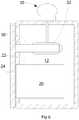
casing 10, which is, in this embodiment, shaped generally as an upright cuboid. Thecasing 10 is constructed to be a reservoir that, in use, contains a volume of water within aninternal space 12. For instance, thecasing 10 may be formed as a one-piece rotational moulding of plastic material. Insulatingmaterial 14 is carried on outer surfaces of thecasing 10 to minimise flow of heat through the casing to or from the water contained within it. The water largely fills theinternal space 12, but a small volume may be left unfilled to allow for expansion. - A
payload space 20 is formed within thecasing 10. Thepayload space 20 is located within a generallycuboidal box 22 that has one open face that opens horizontally to the exterior of the casing. The typical volume of the payload space may be in the range of 50 to 100 litres, but other arrangements, for specialist purposes, may have greater or lesser capacities. The other faces are located within thecasing 10 and are submerged under the water that is contained within thecasing 10. The submerged faces of thecuboidal box 22 have no insulation so that they are in thermal communication with the surrounding water in a cooling region of the reservoir. Thebox 22 may optionally be integrally formed with thecasing 10. When the refrigerator is disposed for use, thepayload space 20 extends from close to the lowermost surface of theinternal space 12 of the casing to appropriately half way towards the uppermost surface of theinternal space 12. - A
door 24 is mounted on thecasing 10. Thedoor 24 can be opened to gain access to thepayload space 20 through the open face. Insulating material is carried on thedoor 24 so that, when it is closed, it minimises the amount of heat that can be transferred through it into or out of thepayload space 20. - A
refrigeration unit 30 is carried on a top surface of thecasing 10. In this embodiment, the refrigeration unit is a conventional electrical compressor-based cooling unit. Therefrigeration unit 30 has acooling element 32 that extends into theinternal space 12 of thecasing 10 and is submerged in the water. Thecooling element 32 is located in a water-filled headspace above thebox 22 such that it is spaced from thebox 22 by a layer of water and likewise spaced from the uppermost surface of theinternal space 12. (Alternatively, therefrigeration unit 30 may have a wrap-around evaporator that surrounds the headspace.) Anoptional ice probe 36 is located within thecasing 10 above thebox 22 but below the cooling element. Theice probe 36 is electrically connected to control therefrigeration unit 30, as will be described below. - The refrigerator has an external power supply to feed the
refrigeration unit 30. The power supply can operate from a supply of mains voltage (derived from a power grid or from a local generator) in the absence of bright sunlight. The power supply can also operate from photovoltaic panels, whereby therefrigeration unit 30 can be run without the need of a mains supply during sunny daytime conditions. - Operation of the refrigerator will now be described.
- When the refrigerator is first started, it can be assumed that all of the water is at or around the ambient temperature. The
refrigeration unit 30 is run to cause itsrefrigeration element 32 to cool to a temperature that is typically well below the freezing point of water - for example, as low as -30°C. This, in turn, causes water in the immediate surroundings of the cooling element to cool. As the water cools, its density increases. This sets up an effect, whereby the cooled water sinks in thecasing 10, so displacing warmer water below. This warmer water rises, and is, in turn, cooled. The average temperature of all of the water within thecasing 10 falls. However, once the temperature of the water surrounding thecooling element 32approaches 4°C, the rate of the effect decreases. This causes the lower part of the water to become comparatively stagnant, with a temperature of around 4°C. The water immediately surrounding the cooling element may fall below this, or may eventually freeze. However, the ice formed by this freezing will be less dense than the warmer water below, so the ice will float upwards. Ice may continue to form, and grow downwards as cooling continues. Once the growing ice reaches and is detected by theice probe 36, power to therefrigeration unit 30 is cut, so no further ice will form. In this embodiment, there is still a clear layer of liquid water between the lowest part of the ice and the top of thebox 22, whereby thebox 22 and anything within the payload space will remain above the freezing point of water. However, the extent to which ice can be allowed to grow in any particular embodiment without potentially harming a payload can be determined by experimentation. - Once the
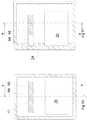
refrigeration unit 30 stops, assuming that ambient temperature is higher than the temperature of the water, energy will pass through the walls of thecasing 10 into the water, which will start to warm. In the reverse of the cooling process, water in the lower part of thecasing 10 will tend to stay around 4°C while the ice melts. Following complete melting, the water will continue to warm, but water above 4°C will tend to rise to the top of thecasing 10. Thus, thepayload space 20 will be maintained at or around 4°C for as long as possible. As is well-known, a large amount of energy is required to melt ice - the latent heat of fusion. This acts as a sink of a large amount of energy that is absorbed by the water, the payload space being maintained at a substantially constant temperature during the time that the ice melts. The payload of the refrigerator is therefore maintained at around 4°C, which is an ideal temperature for storage of vaccine and of food and drink. Figures 4 and 5 show a second embodiment of the invention: this has essentially the same components as the first embodiment. However, their layout is somewhat different. In the following description, components of the second embodiment will be given reference signs that are 100 greater than the corresponding components of the first embodiment.- In the second embodiment, the casing no is comparatively squatter in shape than that of the first embodiment. The opening of the
box 122 faces upwards, and thedoor 124 opens upwards. Water surrounds the box on all sides but for the top opening, with theinternal space 112 including an additional volume adjacent to one side of thebox 122. Asupplementary chamber 160, also containing water, is located on an upper surface of thebox 122 above the additional headspace volume and adjacent to thedoor 124. Apassage 162 interconnects thesupplementary chamber 160 and the additional volume of theinternal space 112 that allows water to pass between them. Anice sensor 136 is located adjacent to thepassage 162 within theinternal space 112. - A
refrigeration unit 130 is carried on an upper surface of thesupplementary chamber 160, with acooling element 132 extending from it into thesupplementary chamber 160. - This embodiment operates substantially as described above. Water that is cooled within the supplementary chamber passes into the
internal space 112 through thepassage 162. As before, the water that is densest - that is atround 4°C - sinks into theinternal space 112 to cool thebox 122 and the payload within it. - The third embodiment, shown in
Figure 6 corresponds closely to the first embodiment ofFigures 2 and 3 , while the fourth embodiment ofFigure 7 corresponds closely to the second embodiment ofFigures 4 and 5 . Therefore, only the additional features present will be described. - The third and fourth embodiments add the ability to maintain items in a frozen condition to the first and second embodiments. The freezer compartment is in close thermal contact with a cooling element, such that it is cooled to a temperature well below that of the water. In the third embodiment, a
freezer compartment 50 is provided, that has similar construction to thepayload space 22, and similarly has a horizontal opening that is closed by thedoor 24. Thefreezer compartment 50 is located directly above the payload space, in close proximity to, or surrounded by, thecooling element 32 of therefrigeration unit 30. - In the fourth embodiment, the opening of the
freezer compartment 150 is horizontal and above that of thepayload space 120. In the fourth embodiment, the opening of thefreezer compartment 150 is horizontal and beside that of thepayload space 120. Thefreezer compartment 150 is enclosed within thesupplementary chamber 160, in close proximity to, or surrounded by, thecooling element 132 of therefrigeration unit 130. In this embodiment, thefreezer compartment 150 has an insulateddoor 152 that is separate from thedoor 124 of thepayload space 120. Thedoor 152 closes a horizontal opening of thefreezer compartment 150. - A fifth embodiment, shown in
Figure 8 , has a somewhat different construction from the previous embodiments, but operates on the same principles. - In this embodiment, the reservoir comprises an
upper compartment 210 mounted above apayload container 220 to form a headspace. The reservoir includes first andsecond water ducts payload container 220. Thefirst duct 214 opens into the headspace at or close to a lowermost wall, while thesecond duct 214 extends upwards into water contained within the headspace. Within thepayload container 220, a manifold ofseveral pipes 216 are connected to flow in parallel between the twoducts cooling elements 232 that can cool water within the headspace. - As with the preceding embodiments, the densest water will tend to flow towards the bottom of the reservoir - in this case, into the
ducts manifold 216 within thepayload container 220, where heat can be exchanged between the water within the reservoir and the contents of thepayload container 220. A thermosiphon process becomes established that transfers heat away from the payload container into the headspace as the temperature of the payload container falls towards 4°C. - In yet further embodiments, there may be several payload containers within the reservoir to allow items that are to be carried to be kept separate.
- As shown in
Figure 9 , when therefrigeration unit payload space 20, 120 (as shown by the trace 40) drops quickly to 4°C, when the temperature stabilises (at 42). The temperature does not drop substantially, notwithstanding thatrefrigeration unit 30 continues to run. At 44, the refrigeration unit stops. The temperature in thepayload space 20 then rises only very slowly for a considerable amount of time before starting to rise more rapidly. In the example shown inFigure 9 , the refrigeration unit runs for 9 hours and 40 minutes before the payload space reaches the maximum tolerable value of 8°C. Approximately an hour later, the temperature has dropped to 4°C. Therefrigeration unit refrigeration unit - This performance is substantially beyond that required by the World Health Organisation for vaccine storage, and is ideally suited for use with a power supply that relies upon energy derived from sunlight. It is significantly more than adequate to maintain the contents at the required temperature overnight, and, should it be necessary, through a period of cloudy weather when the supply of electrical power is limited. It should be noted that this level of performance is reached without any backup source of power such as a rechargeable battery.
- The above description assumes that the maximum density of water occurs at 4°C, which is the case for pure water. The temperature at which the maximum density occurs can be altered by introduction of impurities into the water. For example, if salt is added to the water to a concentration of 3.5% (approximately that of sea water) then the maximum density occurs at nearer 2°C. This can be used to adjust the temperature of the payload space for specific applications.
- Further, simpler alternative embodiments of the invention are shown in
Figures 10 to 13 . The embodiment ofFigures 10 and 11 is similar to the third embodiment, and the embodiment ofFigures 11 and12 is similar to the fourth embodiment. In each case, therefrigeration unit 30, 310 and the associatedcooling element - Instead, in the embodiment of
Figures 10 and 11 , awatertight compartment 64 is provided. Thecompartment 64 extends into the headspace at substantially the same location as thefreezer compartment compartment 64 can be reached from an opening that is closed by adoor compartment 64 is chosen to have a high thermal conductivity to ensure efficient heat transfer between contents of thecompartment 64 and water surrounding it. - For use, the
compartment 64 is filled with a body ofcold material cold material payload space cooling element compartment 64. In this way, thepayload space - The body of cold material can be anything with a suitable thermal mass. However, water ice is particularly suitable because it is readily available and has an advantageously high latent heat of fusion. The ice may be in the form of standard 0.6
litre ice packs 166 that are used in transport and storage of medical supplies. If ice packs are to be used, the compartment could be omitted altogether, with the ice packs being placed directly within the water of the headspace, as shown inFigures 12 and 13 . (Of course, the embodiment ofFigures 12 and 13 could be modified to include a compartment as in the embodiment ofFigures 10 and 11 , and the embodiment ofFigures 10 and 11 could be modified by the omission of the compartment.) - Another embodiment that makes use of a thermal mass is shown in
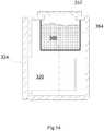
Figure 14 . In this embodiment, acontainer 364 is located above thepayload container 320 submerged in water within the headspace. Thecontainer 364 is formed of a material that allows heat to be transferred from water within the headspace to its contents. Thecontainer 364 has an opening through which its interior can be reached from outside of the refrigerator, the opening being closed by a thermally-insulated cover 352. In this embodiment, the opening of the container faces upward when the refrigerator is in use. - This embodiment functions in a manner similar to those described above that make use of a thermal mass.
Cold material 366, most typically water ice, is introduced into thecontainer 364 through the opening. Heat then moves from water in the headspace to the ice within the container, thereby cooling the water and the contents of thepayload container 320, in accordance with the principles described above. The arrangement of the opening shown inFigure 14 allows the ice to be introduced quickly and easily into the container. - It is surmised that a refrigerator with a payload space of 60 litres can be maintained within a required temperature range for between 7 and 30 days, with a requirement of 100 litres of ice to achieve the upper end of this range.
- Clearly, in all of the above examples, a central requirement is that the water be maintained within the refrigerator in a manner that leakage and evaporation is prevented. This can be quite difficult to achieve for a refrigerator that is likely to be subject to rough handling and shock as it is transported in rugged vehicles on poorly-surfaced roads or entirely off-road. Therefore, one system for constructing a refrigerator embodying the invention is to provide a rigid outer case that provides the overall shape, structural strength and thermal insulation, and to line the case with a
watertight liner 80 formed from flexible plastic material. Such a liner is shown inFigure 15a to 15c . - It will be understood that the
liner 80 will be shaped and dimensioned in accordance with the particular requirements with which it will be used, and that the figures illustrate just one exemplary configuration. The example shown inFigures 15a to 15c will be suitable for use in a front-entry refrigerator. It includes aheadspace 82, a filling pipe 84, and arecess 86 within which the payload space is contained. The weight of the water causes the material of theliner 80 to deflect, so as to conform closely to the payload space, thereby ensuring effective heat transfer between the payload space and water within theliner 80. Small deflections of or damage to the outer case will not result in leakage of theliner 80. In the event that the liner does leak, it can be replaced readily and at little cost.
Claims (14)
- A refrigerator having:a) cooling means;b) a payload container (22, 122), a payload space (20) located within a payload container (22, 122) and within which items can be placed for temperature-controlled storage; andc) a casing (10, 110) constructed to be a reservoir (12, 112) within which water is contained in use, insulating material (14) being carried on outer surfaces of the casing (10, 110) and the reservoir (12, 112) having:i) a cooling region in thermal communication with the payload container (22, 122), the payload container (22, 122) having one open face that opens to the exterior of the casing (10, 110), the other faces being located within the casing (10, 110) and except one of them being submerged,
in use, under the water contained within the casing (10, 110), the submerged faces having no insulation so that they are in thermal communication with the surrounding water in the cooling region of the reservoir (12, 112); andii) a headspace,
characterized in that all said other faces are submerged and belong to said submerged faces, andin that said headspace, in use, contains water and is disposed above the payload container (22, 122) and the cooling region and is in fluid communication therewith, the headspace being configured to permit said cooling means (32, 132; 66, 166) to be disposed therein for cooling water within the headspace. - A refrigerator according to claim 1, wherein the cooling means (32, 132; 66, 166) comprises a thermal mass (66, 166) that, in use, is at a temperature below a target temperature of the payload container (12, 122), the thermal mass (66, 166) optionally being an ice pack or a body of water ice.
- A refrigerator according to claim 1, wherein the cooling means (32, 132; 66, 166) comprises a refrigeration unit (30, 130).
- A refrigerator according to claim 3 comprising a power supply for the refrigeration unit (30, 130), the power supply comprising one of:a mains voltage power source; andmeans for converting sunlight into electrical power, for example a plurality of photovoltaic cells.
- A refrigerator according to claim 3 or 4, wherein the refrigeration unit (30, 130) includes one of:an electrically-powered compressor; anda Stirling cooler being optionally operable in solar direct drive mode.
- A refrigerator according to any of claims 3 to 5 comprising a sensor (36, 136) for detecting the formation of ice in the reservoir (12, 112), the sensor (36, 136) being operable to cause operation of the refrigeration unit (30, 130) to be interrupted upon detection of the formation of ice.
- A refrigerator according to claim 2 comprising a compartment (64) for receiving the thermal mass (66).
- A refrigerator according to any preceding claim comprising one or more water-carrying passages (212, 214, 216) that extend through a payload space.
- A refrigerator according to any preceding claim in which the payload container (22, 122) includes an opening and a closure (24, 124) located, in use:on one side of the payload container (22); oron top of the payload container (122).
- A refrigerator according to claim 9 in which the closure (24, 124) is an insulated door carried on the reservoir (12, 112).
- A refrigerator according to any preceding claim that further includes a freezer compartment (50, 150) that is, in use, in close thermal communication with the cooling means (32, 132; 66, 166).
- A refrigerator according to claim 11 in which the freezer compartment (50, 150) has an opening that is closed by an insulated door (24, 152), the insulated door (24) optionally also closing the payload container (22).
- A refrigerator according to any preceding claim, wherein the casing (10, 110) comprises an outer case within which is contained a liquid-containing liner (80), optionally formed of flexible plastic material.
- A refrigerator according to claim 13 in which the outer case provides structural strength and thermal insulation for the refrigerator.
Applications Claiming Priority (3)
| Application Number | Priority Date | Filing Date | Title |
|---|---|---|---|
| GB0912286AGB2471865B (en) | 2009-07-15 | 2009-07-15 | Refrigeration apparatus |
| GB0916160AGB2471910A (en) | 2009-07-15 | 2009-09-15 | Refrigerator with a Container in Thermal Communication with a Water-Filled Reservoir |
| PCT/GB2010/051129WO2011007162A2 (en) | 2009-07-15 | 2010-07-09 | Refrigeration apparatus |
Publications (2)
| Publication Number | Publication Date |
|---|---|
| EP2454539A2 EP2454539A2 (en) | 2012-05-23 |
| EP2454539B1true EP2454539B1 (en) | 2017-11-08 |
Family
ID=41057993
Family Applications (1)
| Application Number | Title | Priority Date | Filing Date |
|---|---|---|---|
| EP10739675.6AActiveEP2454539B1 (en) | 2009-07-15 | 2010-07-09 | Refrigeration apparatus |
Country Status (20)
| Country | Link |
|---|---|
| US (1) | US9618253B2 (en) |
| EP (1) | EP2454539B1 (en) |
| JP (2) | JP5852567B2 (en) |
| KR (1) | KR101807171B1 (en) |
| CN (2) | CN104976843B (en) |
| AP (1) | AP3883A (en) |
| AU (1) | AU2010272320B2 (en) |
| BR (1) | BRPI1015971B1 (en) |
| CA (1) | CA2767864C (en) |
| CO (1) | CO6612198A2 (en) |
| DK (1) | DK2454539T5 (en) |
| EA (2) | EA030939B1 (en) |
| GB (5) | GB2471865B (en) |
| MA (1) | MA33494B1 (en) |
| MX (1) | MX338104B (en) |
| MY (1) | MY154163A (en) |
| SG (1) | SG176991A1 (en) |
| TN (1) | TN2012000018A1 (en) |
| WO (1) | WO2011007162A2 (en) |
| ZA (2) | ZA201103063B (en) |
Cited By (1)
| Publication number | Priority date | Publication date | Assignee | Title |
|---|---|---|---|---|
| FR3139623A1 (en) | 2022-07-26 | 2024-03-15 | Koolboks | Renewable energy refrigeration system including refrigerated cabinet |
Families Citing this family (28)
| Publication number | Priority date | Publication date | Assignee | Title |
|---|---|---|---|---|
| GB2471865B (en) | 2009-07-15 | 2011-06-29 | Bright Light Solar Ltd | Refrigeration apparatus |
| GB2514502B (en)* | 2012-01-27 | 2019-07-03 | The Sure Chill Company Ltd | Refrigeration apparatus |
| GB201300885D0 (en)* | 2013-01-17 | 2013-03-06 | True Energy Ltd | Cooling Apparatus |
| GB201301494D0 (en)* | 2013-01-28 | 2013-03-13 | True Energy Ltd | Refrigeration apparatus |
| US11105556B2 (en) | 2013-03-29 | 2021-08-31 | Tokitae, LLC | Temperature-controlled portable cooling units |
| WO2015011477A1 (en) | 2013-07-23 | 2015-01-29 | The Sure Chill Company Limited | Refrigeration apparatus and method |
| US9366483B2 (en) | 2013-11-27 | 2016-06-14 | Tokitac LLC | Temperature-controlled container systems for use within a refrigeration device |
| US9726418B2 (en) | 2013-11-27 | 2017-08-08 | Tokitae Llc | Refrigeration devices including temperature-controlled container systems |
| US9523522B2 (en) | 2013-11-27 | 2016-12-20 | Tokitae Llc | Refrigeration devices including temperature-controlled container systems |
| WO2016022681A1 (en)* | 2014-08-08 | 2016-02-11 | Tokitae Llc | Temperature-controlled medicinal storage devices |
| CN105987555A (en)* | 2015-03-06 | 2016-10-05 | 青岛海尔股份有限公司 | Ice-water cold storage constant-temperature refrigerated container and control method |
| EP3280962B1 (en)* | 2015-04-06 | 2019-05-22 | The Sure Chill Company Limited | Mobile refrigeration apparatus |
| US10704822B2 (en) | 2015-09-11 | 2020-07-07 | The Sure Chill Company Limited | Portable refrigeration apparatus |
| JP6090407B1 (en)* | 2015-10-27 | 2017-03-08 | 三菱電機株式会社 | Storage movement device |
| CN106500386B (en)* | 2016-12-28 | 2022-12-30 | 宁波华斯特林电机制造有限公司 | Cooling device based on Stirling motor |
| DK3589901T3 (en)* | 2017-02-28 | 2021-05-25 | B Medical Systems Sarl | VACCINE CARRIER WITH A PASSIVE COOLING SYSTEM |
| CN108895742A (en)* | 2018-04-13 | 2018-11-27 | 西安工程大学 | A kind of novel portable domestic refrigerator |
| EP3781884A1 (en) | 2018-04-19 | 2021-02-24 | Ember Technologies, Inc. | Portable cooler with active temperature control |
| GB2575859B (en)* | 2018-07-26 | 2022-03-30 | B Medical Systems Sarl | Ice-lined vaccine refrigerator |
| CA3125017A1 (en) | 2019-01-11 | 2020-07-16 | Ember Technologies, Inc. | Portable cooler with active temperature control |
| US11668508B2 (en) | 2019-06-25 | 2023-06-06 | Ember Technologies, Inc. | Portable cooler |
| US11162716B2 (en) | 2019-06-25 | 2021-11-02 | Ember Technologies, Inc. | Portable cooler |
| EP4621318A2 (en) | 2019-06-25 | 2025-09-24 | YETI Coolers, LLC | Portable cooler |
| WO2021150241A1 (en)* | 2020-01-24 | 2021-07-29 | Nobotech, Llc | Regulator system and method for regulating liquid bulk gas containers |
| JP2023521040A (en) | 2020-04-03 | 2023-05-23 | エンバー ライフサイエンシズ, インコーポレイテッド | Portable cooler with active temperature control |
| PE20231665A1 (en) | 2020-09-30 | 2023-10-19 | Owens Brockway Glass Container | SUBMERGED LOADING OF RAW MATERIALS FROM FUSION VESSELS |
| CN114735336B (en)* | 2022-06-09 | 2022-08-30 | 郑州人民医院(郑州人民医院医疗管理中心) | A kidney transport storage tank |
| KR20240045503A (en) | 2022-09-30 | 2024-04-08 | 충남대학교산학협력단 | A supercooled preservation device for preventing freezing damage of a vaccine |
Citations (1)
| Publication number | Priority date | Publication date | Assignee | Title |
|---|---|---|---|---|
| US4321802A (en)* | 1979-07-05 | 1982-03-30 | Hoshizaki Electric Co., Ltd. | Ice and water-making refrigeration apparatus |
Family Cites Families (78)
| Publication number | Priority date | Publication date | Assignee | Title |
|---|---|---|---|---|
| US186200A (en) | 1877-01-16 | Improvement in refrigerators | ||
| GB165684A (en)* | 1920-08-16 | 1921-07-07 | Fred John Heideman | Improvements in refrigerating tanks for refrigerators |
| US1594015A (en) | 1926-01-19 | 1926-07-27 | Mclaughlin William | Beverage cooler and dispenser |
| US1988549A (en) | 1930-09-30 | 1935-01-22 | Frigidaire Corp | Refrigerating apparatus |
| US2046967A (en) | 1932-08-03 | 1936-07-07 | Int Motor Co | Refrigerating mechanism |
| GB494531A (en) | 1937-06-08 | 1938-10-27 | Harry Aldam | Improvements in or relating to refrigeration apparatus |
| US2641109A (en) | 1947-08-29 | 1953-06-09 | Muffly Glenn | Multitemperature refrigerating system |
| JPS4827260B1 (en)* | 1967-08-08 | 1973-08-21 | ||
| US3609991A (en) | 1969-10-13 | 1971-10-05 | Ibm | Cooling system having thermally induced circulation |
| JPS4936282Y1 (en)* | 1970-10-07 | 1974-10-03 | ||
| GB1429678A (en) | 1973-03-28 | 1976-03-24 | Distillers Co Carbon Dioxide | Apparatus for supplying liquid carbon dioxide |
| SU898226A1 (en)* | 1979-09-21 | 1982-01-15 | Львовский Ордена Ленина Политехнический Институт Им. Ленинского Комсомола | Domestic thermoelectric refrigerator |
| JPS614190Y2 (en)* | 1979-11-06 | 1986-02-08 | ||
| EP0038864A1 (en)* | 1980-04-24 | 1981-11-04 | Eberlein & Co. | Cold-storage box |
| US4509587A (en) | 1982-08-30 | 1985-04-09 | Clark Thomas S | Passive temperature control shipment container |
| FR2537712A1 (en) | 1982-12-08 | 1984-06-15 | Droit Philippe | Heat exchanger for temperature conditioning apparatus |
| JPS60108977U (en)* | 1983-12-28 | 1985-07-24 | 株式会社東芝 | hot and cold water machine |
| FR2562218B1 (en)* | 1984-03-29 | 1987-03-20 | Elf Aquitaine | SOLAR ENERGY SUPPLIED REFRIGERATOR |
| DD240333A1 (en) | 1985-08-19 | 1986-10-29 | Univ Rostock | KUEHLCONTAINER ESPECIALLY FOR DONATION ORGANS |
| JPS63113872U (en)* | 1987-01-19 | 1988-07-22 | ||
| US4715195A (en) | 1987-06-02 | 1987-12-29 | Iosif Kucza | Apparatus for rapid cooling of containers |
| FR2628077B1 (en)* | 1988-03-07 | 1990-08-03 | Guilhem Jacques | CONTAINER FOR TRANSPORTING GRAFT |
| CN2062629U (en) | 1988-12-30 | 1990-09-26 | 李耀忠 | Multifunctional effector for qigong |
| GB2235968B (en) | 1989-08-11 | 1993-01-13 | Booth Dispensers | Improvements in or relating to heat exchange |
| FR2660738B1 (en)* | 1990-04-05 | 1994-10-28 | Cma | INSTALLATION FOR FAST REFRIGERATION (OR HEATING) OF PACKAGED PRODUCTS, ESPECIALLY BOTTLES. |
| JPH0725578Y2 (en)* | 1990-11-07 | 1995-06-07 | 大同ほくさん株式会社 | Cooling and freeze cooling device |
| US5129238A (en) | 1990-11-30 | 1992-07-14 | Schwartz James A | Soft drink container cooler |
| BE1004012A3 (en) | 1990-12-17 | 1992-09-08 | F R J Concept | Refresh device for liquids contained in containers. |
| CA2140517C (en) | 1991-03-20 | 1998-06-30 | Yutaka Hachinohe | Low temperature food storage process |
| JPH0744929Y2 (en)* | 1991-05-28 | 1995-10-11 | ホシザキ電機株式会社 | Ice storage with chilled water supply |
| JP3108155B2 (en)* | 1991-09-19 | 2000-11-13 | 三洋電機株式会社 | Cold water case |
| DE4142842A1 (en) | 1991-09-26 | 1993-04-01 | Wolfgang Wasserthal | Portable cool container pref. powered from solar energy or car battery - has insulated cover, lower part and gravity-operated coolant |
| JPH05248754A (en)* | 1992-03-09 | 1993-09-24 | Sanyo Electric Co Ltd | Cooling chamber |
| WO1994012836A1 (en)* | 1992-11-20 | 1994-06-09 | Grumman Aerospace Corporation | Self-contained cooler/freezer apparatus |
| US5627310A (en)* | 1992-12-10 | 1997-05-06 | Imi Cornelius, Inc. | Sensor arrangement for ice bank control |
| CN2162269Y (en) | 1993-06-18 | 1994-04-20 | 郁苏 | Luminous Chinese checkers |
| US5408845A (en) | 1993-09-08 | 1995-04-25 | Microchill Int Ltd | Cooling or chilling apparatus |
| DE4425213A1 (en)* | 1994-07-16 | 1996-01-18 | Helmut Kuhn | Solar-powered cool box |
| JPH10144361A (en) | 1996-11-12 | 1998-05-29 | Furukawa Electric Co Ltd:The | Battery system and transport machine equipped with it |
| US5782095A (en) | 1997-09-18 | 1998-07-21 | General Electric Company | Cryogen recondensing superconducting magnet |
| US6253563B1 (en)* | 1999-06-03 | 2001-07-03 | The United States Of America As Represented By The Administrator Of The National Aeronautics And Space Administration | Solar-powered refrigeration system |
| CN2379760Y (en) | 1999-06-09 | 2000-05-24 | 李丽芬 | Beverage Barrel Cooling Device |
| JP2001133109A (en)* | 1999-10-29 | 2001-05-18 | Toshiba Electric Appliance Co Ltd | Cold water pour-out device |
| JP2001221553A (en)* | 2000-02-07 | 2001-08-17 | Sharp Corp | Cool box |
| JP2001227847A (en)* | 2000-02-14 | 2001-08-24 | Masashi Ogoshi | Ice making machine having ice cooler chamber |
| CN1426523A (en)* | 2000-04-27 | 2003-06-25 | 夏普公司 | Cold insulation chamber |
| JP3614349B2 (en) | 2000-06-27 | 2005-01-26 | 象印マホービン株式会社 | Liquid container cooling device |
| US6415624B1 (en) | 2000-08-25 | 2002-07-09 | Frank R. Connors | Drinking bottle having a separate thermally regulating container |
| US6314751B1 (en) | 2000-11-17 | 2001-11-13 | Gilbert Sebastian Gjersvik | Beverage chilling apparatus |
| US20020104318A1 (en)* | 2001-02-08 | 2002-08-08 | Ali Jaafar | Miniature thermoelectric cooler |
| US6656380B2 (en)* | 2001-10-16 | 2003-12-02 | Supachill Technologies Pty. Ltd. | Super-coolable composition having long-duration phase change capability, process for preparation of same, process for super-cooling same and articles comprising same |
| JP2003148849A (en)* | 2001-11-06 | 2003-05-21 | Biobank Co Ltd | Portable refrigerating container for organ for medical application |
| JP4556019B2 (en)* | 2002-05-24 | 2010-10-06 | 日本通運株式会社 | Cooling container for delivery |
| US7069739B2 (en) | 2002-12-18 | 2006-07-04 | Porter Michael A | Device for cooling or heating liquids in a bottle |
| DE10261366A1 (en) | 2002-12-30 | 2004-07-08 | BSH Bosch und Siemens Hausgeräte GmbH | Auxiliary cooling device |
| RU2361495C2 (en)* | 2003-03-24 | 2009-07-20 | Унилевер Нв | Coolable device for demonstration and distribution |
| SE0303234D0 (en) | 2003-12-01 | 2003-12-01 | Dometic Sweden Ab | Refrigerator and method |
| US6948333B1 (en) | 2004-04-19 | 2005-09-27 | Akopyan Arshak Sh | Combined bottles with hidden cooler |
| US7296434B2 (en)* | 2004-06-22 | 2007-11-20 | Scroggs Donald T | Cooler |
| KR101289137B1 (en) | 2004-07-22 | 2013-07-23 | 이알에이(인바이런멘틀 리프리저레이션 올터너티브스) 피티와이 엘티디 | Refrigeration system |
| JP2007085635A (en)* | 2005-09-21 | 2007-04-05 | Twinbird Corp | Liquid cooling device |
| GB2430724B (en) | 2005-09-28 | 2007-09-12 | Yiu Wing Ng | Bottle cooler |
| KR100729962B1 (en)* | 2005-10-21 | 2007-06-19 | 청호나이스 주식회사 | Cold and hot water purification system and device that can get cold water at the same time with one evaporator |
| US20090151368A1 (en)* | 2006-08-08 | 2009-06-18 | Ewa Tech Ltd. | Method and apparatus for extracting water from atmospheric air and utilizing the same |
| US7640764B2 (en) | 2006-09-08 | 2010-01-05 | Adroit Medical Systems, Inc. | Portable coolant system |
| JP2008086608A (en)* | 2006-10-03 | 2008-04-17 | Twinbird Corp | Carrier of blood product |
| DE102006058629B3 (en) | 2006-12-13 | 2008-07-10 | Schuler Pressen Gmbh & Co. Kg | Cooling arrangement for a capacitor |
| JP2009030961A (en) | 2007-06-29 | 2009-02-12 | Mutsu Tsunoda | Cooling chamber |
| NL2001054C2 (en) | 2007-12-04 | 2009-06-08 | Heineken Supply Chain Bv | Cooler and method for cooling beverage containers such as bottles and cans. |
| GB2457054B (en) | 2008-01-31 | 2010-01-06 | Siemens Magnet Technology Ltd | A method and apparatus for controlling the cooling power of a cryogenic refigerator delivered to a cryogen vessel |
| US7543455B1 (en)* | 2008-06-06 | 2009-06-09 | Chengjun Julian Chen | Solar-powered refrigerator using a mixture of glycerin, alcohol and water to store energy |
| DE102009006426A1 (en) | 2009-01-28 | 2010-07-29 | Li-Tec Battery Gmbh | Battery with housing |
| GB2471865B (en) | 2009-07-15 | 2011-06-29 | Bright Light Solar Ltd | Refrigeration apparatus |
| CN201451827U (en) | 2009-07-21 | 2010-05-12 | 成都峻峰科技开发有限公司 | Fresh-keeping lunch box |
| CN103988144B (en) | 2011-12-13 | 2018-06-19 | 英特尔公司 | Use the computing device cooling technology from pumping fluid |
| GB2514502B (en) | 2012-01-27 | 2019-07-03 | The Sure Chill Company Ltd | Refrigeration apparatus |
| GB201301494D0 (en) | 2013-01-28 | 2013-03-13 | True Energy Ltd | Refrigeration apparatus |
| WO2015011477A1 (en) | 2013-07-23 | 2015-01-29 | The Sure Chill Company Limited | Refrigeration apparatus and method |
- 2009
- 2009-07-15GBGB0912286Apatent/GB2471865B/enactiveActive
- 2009-09-15GBGB1115918.3Apatent/GB2482993B/enactiveActive
- 2009-09-15GBGB0916160Apatent/GB2471910A/ennot_activeWithdrawn
- 2010
- 2010-07-09BRBRPI1015971-1Apatent/BRPI1015971B1/enactiveIP Right Grant
- 2010-07-09MYMYPI2011006368Apatent/MY154163A/enunknown
- 2010-07-09EPEP10739675.6Apatent/EP2454539B1/enactiveActive
- 2010-07-09GBGB1202625.8Apatent/GB2486094B/enactiveActive
- 2010-07-09JPJP2012520097Apatent/JP5852567B2/enactiveActive
- 2010-07-09EAEA201790498Apatent/EA030939B1/ennot_activeIP Right Cessation
- 2010-07-09USUS13/383,118patent/US9618253B2/enactiveActive
- 2010-07-09CACA2767864Apatent/CA2767864C/enactiveActive
- 2010-07-09MAMA34536Apatent/MA33494B1/enunknown
- 2010-07-09EAEA201270161Apatent/EA027555B9/ennot_activeIP Right Cessation
- 2010-07-09WOPCT/GB2010/051129patent/WO2011007162A2/enactiveApplication Filing
- 2010-07-09DKDK10739675.6Tpatent/DK2454539T5/enactive
- 2010-07-09AUAU2010272320Apatent/AU2010272320B2/enactiveActive
- 2010-07-09KRKR1020127000384Apatent/KR101807171B1/enactiveActive
- 2010-07-09CNCN201510186465.5Apatent/CN104976843B/enactiveActive
- 2010-07-09SGSG2011096609Apatent/SG176991A1/enunknown
- 2010-07-09MXMX2012000719Apatent/MX338104B/enactiveIP Right Grant
- 2010-07-09CNCN201080041090.9Apatent/CN102483280B/enactiveActive
- 2010-07-09APAP2012006111Apatent/AP3883A/enactive
- 2011
- 2011-04-21ZAZA2011/03063Apatent/ZA201103063B/enunknown
- 2011-09-13GBGBGB1115835.9Apatent/GB201115835D0/ennot_activeCeased
- 2012
- 2012-01-13TNTNP2012000018Apatent/TN2012000018A1/enunknown
- 2012-02-15COCO12026762Apatent/CO6612198A2/enunknown
- 2012-09-07ZAZA2012/06710Apatent/ZA201206710B/enunknown
- 2015
- 2015-12-03JPJP2015236753Apatent/JP2016029334A/enactivePending
Patent Citations (1)
| Publication number | Priority date | Publication date | Assignee | Title |
|---|---|---|---|---|
| US4321802A (en)* | 1979-07-05 | 1982-03-30 | Hoshizaki Electric Co., Ltd. | Ice and water-making refrigeration apparatus |
Cited By (1)
| Publication number | Priority date | Publication date | Assignee | Title |
|---|---|---|---|---|
| FR3139623A1 (en) | 2022-07-26 | 2024-03-15 | Koolboks | Renewable energy refrigeration system including refrigerated cabinet |
Also Published As
Similar Documents
| Publication | Publication Date | Title |
|---|---|---|
| EP2454539B1 (en) | Refrigeration apparatus | |
| US9909799B2 (en) | Refrigeration apparatus | |
| EP3341665B1 (en) | Portable refrigeration system and chilling panel | |
| US6308518B1 (en) | Thermal barrier enclosure system | |
| KR102155595B1 (en) | Refrigeration apparatus | |
| CN107567571B (en) | Cooling device | |
| US9644882B2 (en) | Refrigeration apparatus and method | |
| GB2503191A (en) | Refrigeration apparatus comprising fluid reservoirs | |
| AU2015202391A1 (en) | Refrigeration apparatus | |
| GB2498777A (en) | Refrigeration apparatus with fluid control between a reservoir and a headspace |
Legal Events
| Date | Code | Title | Description |
|---|---|---|---|
| PUAI | Public reference made under article 153(3) epc to a published international application that has entered the european phase | Free format text:ORIGINAL CODE: 0009012 | |
| 17P | Request for examination filed | Effective date:20120215 | |
| AK | Designated contracting states | Kind code of ref document:A2 Designated state(s):AL AT BE BG CH CY CZ DE DK EE ES FI FR GB GR HR HU IE IS IT LI LT LU LV MC MK MT NL NO PL PT RO SE SI SK SM TR | |
| DAX | Request for extension of the european patent (deleted) | ||
| 17Q | First examination report despatched | Effective date:20160217 | |
| REG | Reference to a national code | Ref country code:DE Ref legal event code:R079 Ref document number:602010046537 Country of ref document:DE Free format text:PREVIOUS MAIN CLASS: F25D0011000000 Ipc:F25B0027000000 | |
| GRAP | Despatch of communication of intention to grant a patent | Free format text:ORIGINAL CODE: EPIDOSNIGR1 | |
| RIC1 | Information provided on ipc code assigned before grant | Ipc:F25B 27/00 20060101AFI20170427BHEP Ipc:F25D 16/00 20060101ALI20170427BHEP Ipc:F25D 11/00 20060101ALI20170427BHEP | |
| INTG | Intention to grant announced | Effective date:20170524 | |
| RAP1 | Party data changed (applicant data changed or rights of an application transferred) | Owner name:THE SURE CHILL COMPANY LIMITED | |
| GRAS | Grant fee paid | Free format text:ORIGINAL CODE: EPIDOSNIGR3 | |
| GRAA | (expected) grant | Free format text:ORIGINAL CODE: 0009210 | |
| AK | Designated contracting states | Kind code of ref document:B1 Designated state(s):AL AT BE BG CH CY CZ DE DK EE ES FI FR GB GR HR HU IE IS IT LI LT LU LV MC MK MT NL NO PL PT RO SE SI SK SM TR | |
| REG | Reference to a national code | Ref country code:GB Ref legal event code:FG4D | |
| REG | Reference to a national code | Ref country code:CH Ref legal event code:EP Ref country code:AT Ref legal event code:REF Ref document number:944515 Country of ref document:AT Kind code of ref document:T Effective date:20171115 | |
| REG | Reference to a national code | Ref country code:IE Ref legal event code:FG4D | |
| REG | Reference to a national code | Ref country code:DE Ref legal event code:R096 Ref document number:602010046537 Country of ref document:DE | |
| REG | Reference to a national code | Ref country code:DK Ref legal event code:T3 Effective date:20180206 | |
| REG | Reference to a national code | Ref country code:DK Ref legal event code:T5 Effective date:20180212 | |
| REG | Reference to a national code | Ref country code:NL Ref legal event code:MP Effective date:20171108 | |
| REG | Reference to a national code | Ref country code:LT Ref legal event code:MG4D | |
| REG | Reference to a national code | Ref country code:AT Ref legal event code:MK05 Ref document number:944515 Country of ref document:AT Kind code of ref document:T Effective date:20171108 | |
| PG25 | Lapsed in a contracting state [announced via postgrant information from national office to epo] | Ref country code:LT Free format text:LAPSE BECAUSE OF FAILURE TO SUBMIT A TRANSLATION OF THE DESCRIPTION OR TO PAY THE FEE WITHIN THE PRESCRIBED TIME-LIMIT Effective date:20171108 Ref country code:SE Free format text:LAPSE BECAUSE OF FAILURE TO SUBMIT A TRANSLATION OF THE DESCRIPTION OR TO PAY THE FEE WITHIN THE PRESCRIBED TIME-LIMIT Effective date:20171108 Ref country code:FI Free format text:LAPSE BECAUSE OF FAILURE TO SUBMIT A TRANSLATION OF THE DESCRIPTION OR TO PAY THE FEE WITHIN THE PRESCRIBED TIME-LIMIT Effective date:20171108 Ref country code:NO Free format text:LAPSE BECAUSE OF FAILURE TO SUBMIT A TRANSLATION OF THE DESCRIPTION OR TO PAY THE FEE WITHIN THE PRESCRIBED TIME-LIMIT Effective date:20180208 Ref country code:ES Free format text:LAPSE BECAUSE OF FAILURE TO SUBMIT A TRANSLATION OF THE DESCRIPTION OR TO PAY THE FEE WITHIN THE PRESCRIBED TIME-LIMIT Effective date:20171108 Ref country code:NL Free format text:LAPSE BECAUSE OF FAILURE TO SUBMIT A TRANSLATION OF THE DESCRIPTION OR TO PAY THE FEE WITHIN THE PRESCRIBED TIME-LIMIT Effective date:20171108 | |
| PG25 | Lapsed in a contracting state [announced via postgrant information from national office to epo] | Ref country code:BG Free format text:LAPSE BECAUSE OF FAILURE TO SUBMIT A TRANSLATION OF THE DESCRIPTION OR TO PAY THE FEE WITHIN THE PRESCRIBED TIME-LIMIT Effective date:20180208 Ref country code:HR Free format text:LAPSE BECAUSE OF FAILURE TO SUBMIT A TRANSLATION OF THE DESCRIPTION OR TO PAY THE FEE WITHIN THE PRESCRIBED TIME-LIMIT Effective date:20171108 Ref country code:GR Free format text:LAPSE BECAUSE OF FAILURE TO SUBMIT A TRANSLATION OF THE DESCRIPTION OR TO PAY THE FEE WITHIN THE PRESCRIBED TIME-LIMIT Effective date:20180209 Ref country code:LV Free format text:LAPSE BECAUSE OF FAILURE TO SUBMIT A TRANSLATION OF THE DESCRIPTION OR TO PAY THE FEE WITHIN THE PRESCRIBED TIME-LIMIT Effective date:20171108 Ref country code:IS Free format text:LAPSE BECAUSE OF FAILURE TO SUBMIT A TRANSLATION OF THE DESCRIPTION OR TO PAY THE FEE WITHIN THE PRESCRIBED TIME-LIMIT Effective date:20180308 Ref country code:AT Free format text:LAPSE BECAUSE OF FAILURE TO SUBMIT A TRANSLATION OF THE DESCRIPTION OR TO PAY THE FEE WITHIN THE PRESCRIBED TIME-LIMIT Effective date:20171108 | |
| REG | Reference to a national code | Ref country code:FR Ref legal event code:PLFP Year of fee payment:9 | |
| PG25 | Lapsed in a contracting state [announced via postgrant information from national office to epo] | Ref country code:SK Free format text:LAPSE BECAUSE OF FAILURE TO SUBMIT A TRANSLATION OF THE DESCRIPTION OR TO PAY THE FEE WITHIN THE PRESCRIBED TIME-LIMIT Effective date:20171108 Ref country code:CZ Free format text:LAPSE BECAUSE OF FAILURE TO SUBMIT A TRANSLATION OF THE DESCRIPTION OR TO PAY THE FEE WITHIN THE PRESCRIBED TIME-LIMIT Effective date:20171108 Ref country code:CY Free format text:LAPSE BECAUSE OF FAILURE TO SUBMIT A TRANSLATION OF THE DESCRIPTION OR TO PAY THE FEE WITHIN THE PRESCRIBED TIME-LIMIT Effective date:20171108 Ref country code:EE Free format text:LAPSE BECAUSE OF FAILURE TO SUBMIT A TRANSLATION OF THE DESCRIPTION OR TO PAY THE FEE WITHIN THE PRESCRIBED TIME-LIMIT Effective date:20171108 | |
| REG | Reference to a national code | Ref country code:DE Ref legal event code:R097 Ref document number:602010046537 Country of ref document:DE | |
| PG25 | Lapsed in a contracting state [announced via postgrant information from national office to epo] | Ref country code:PL Free format text:LAPSE BECAUSE OF FAILURE TO SUBMIT A TRANSLATION OF THE DESCRIPTION OR TO PAY THE FEE WITHIN THE PRESCRIBED TIME-LIMIT Effective date:20171108 Ref country code:SM Free format text:LAPSE BECAUSE OF FAILURE TO SUBMIT A TRANSLATION OF THE DESCRIPTION OR TO PAY THE FEE WITHIN THE PRESCRIBED TIME-LIMIT Effective date:20171108 Ref country code:IT Free format text:LAPSE BECAUSE OF FAILURE TO SUBMIT A TRANSLATION OF THE DESCRIPTION OR TO PAY THE FEE WITHIN THE PRESCRIBED TIME-LIMIT Effective date:20171108 Ref country code:RO Free format text:LAPSE BECAUSE OF FAILURE TO SUBMIT A TRANSLATION OF THE DESCRIPTION OR TO PAY THE FEE WITHIN THE PRESCRIBED TIME-LIMIT Effective date:20171108 | |
| PLBE | No opposition filed within time limit | Free format text:ORIGINAL CODE: 0009261 | |
| STAA | Information on the status of an ep patent application or granted ep patent | Free format text:STATUS: NO OPPOSITION FILED WITHIN TIME LIMIT | |
| 26N | No opposition filed | Effective date:20180809 | |
| PG25 | Lapsed in a contracting state [announced via postgrant information from national office to epo] | Ref country code:SI Free format text:LAPSE BECAUSE OF FAILURE TO SUBMIT A TRANSLATION OF THE DESCRIPTION OR TO PAY THE FEE WITHIN THE PRESCRIBED TIME-LIMIT Effective date:20171108 | |
| REG | Reference to a national code | Ref country code:CH Ref legal event code:PL | |
| PG25 | Lapsed in a contracting state [announced via postgrant information from national office to epo] | Ref country code:MC Free format text:LAPSE BECAUSE OF FAILURE TO SUBMIT A TRANSLATION OF THE DESCRIPTION OR TO PAY THE FEE WITHIN THE PRESCRIBED TIME-LIMIT Effective date:20171108 | |
| REG | Reference to a national code | Ref country code:BE Ref legal event code:MM Effective date:20180731 | |
| REG | Reference to a national code | Ref country code:IE Ref legal event code:MM4A | |
| PG25 | Lapsed in a contracting state [announced via postgrant information from national office to epo] | Ref country code:CH Free format text:LAPSE BECAUSE OF NON-PAYMENT OF DUE FEES Effective date:20180731 Ref country code:IE Free format text:LAPSE BECAUSE OF NON-PAYMENT OF DUE FEES Effective date:20180709 Ref country code:LI Free format text:LAPSE BECAUSE OF NON-PAYMENT OF DUE FEES Effective date:20180731 | |
| PG25 | Lapsed in a contracting state [announced via postgrant information from national office to epo] | Ref country code:BE Free format text:LAPSE BECAUSE OF NON-PAYMENT OF DUE FEES Effective date:20180731 | |
| PG25 | Lapsed in a contracting state [announced via postgrant information from national office to epo] | Ref country code:MT Free format text:LAPSE BECAUSE OF NON-PAYMENT OF DUE FEES Effective date:20180709 | |
| PG25 | Lapsed in a contracting state [announced via postgrant information from national office to epo] | Ref country code:TR Free format text:LAPSE BECAUSE OF FAILURE TO SUBMIT A TRANSLATION OF THE DESCRIPTION OR TO PAY THE FEE WITHIN THE PRESCRIBED TIME-LIMIT Effective date:20171108 | |
| PG25 | Lapsed in a contracting state [announced via postgrant information from national office to epo] | Ref country code:HU Free format text:LAPSE BECAUSE OF FAILURE TO SUBMIT A TRANSLATION OF THE DESCRIPTION OR TO PAY THE FEE WITHIN THE PRESCRIBED TIME-LIMIT; INVALID AB INITIO Effective date:20100709 Ref country code:PT Free format text:LAPSE BECAUSE OF FAILURE TO SUBMIT A TRANSLATION OF THE DESCRIPTION OR TO PAY THE FEE WITHIN THE PRESCRIBED TIME-LIMIT Effective date:20171108 | |
| PG25 | Lapsed in a contracting state [announced via postgrant information from national office to epo] | Ref country code:MK Free format text:LAPSE BECAUSE OF NON-PAYMENT OF DUE FEES Effective date:20171108 | |
| PG25 | Lapsed in a contracting state [announced via postgrant information from national office to epo] | Ref country code:AL Free format text:LAPSE BECAUSE OF FAILURE TO SUBMIT A TRANSLATION OF THE DESCRIPTION OR TO PAY THE FEE WITHIN THE PRESCRIBED TIME-LIMIT Effective date:20171108 | |
| P01 | Opt-out of the competence of the unified patent court (upc) registered | Effective date:20230815 | |
| PGFP | Annual fee paid to national office [announced via postgrant information from national office to epo] | Ref country code:GB Payment date:20240530 Year of fee payment:15 | |
| PGFP | Annual fee paid to national office [announced via postgrant information from national office to epo] | Ref country code:LU Payment date:20240626 Year of fee payment:15 | |
| PGFP | Annual fee paid to national office [announced via postgrant information from national office to epo] | Ref country code:FR Payment date:20240611 Year of fee payment:15 | |
| PGFP | Annual fee paid to national office [announced via postgrant information from national office to epo] | Ref country code:DE Payment date:20240604 Year of fee payment:15 | |
| PGFP | Annual fee paid to national office [announced via postgrant information from national office to epo] | Ref country code:DK Payment date:20240712 Year of fee payment:15 |