EP2454160B1 - A storage device and storage system - Google Patents
A storage device and storage systemDownload PDFInfo
- Publication number
- EP2454160B1 EP2454160B1EP10739878.6AEP10739878AEP2454160B1EP 2454160 B1EP2454160 B1EP 2454160B1EP 10739878 AEP10739878 AEP 10739878AEP 2454160 B1EP2454160 B1EP 2454160B1
- Authority
- EP
- European Patent Office
- Prior art keywords
- locking
- cover frame
- storage device
- side wall
- container
- Prior art date
- Legal status (The legal status is an assumption and is not a legal conclusion. Google has not performed a legal analysis and makes no representation as to the accuracy of the status listed.)
- Not-in-force
Links
- 239000000463materialSubstances0.000claimsdescription11
- 239000002991molded plasticSubstances0.000claimsdescription6
- 238000013022ventingMethods0.000description13
- 238000010276constructionMethods0.000description8
- 239000000428dustSubstances0.000description7
- 230000003019stabilising effectEffects0.000description6
- 230000000844anti-bacterial effectEffects0.000description5
- 230000000843anti-fungal effectEffects0.000description5
- 229940121375antifungal agentDrugs0.000description4
- 238000007789sealingMethods0.000description4
- 239000000126substanceSubstances0.000description4
- 238000009423ventilationMethods0.000description4
- 238000005273aerationMethods0.000description3
- 230000014759maintenance of locationEffects0.000description3
- 229920003023plasticPolymers0.000description3
- 239000004033plasticSubstances0.000description2
- 230000006641stabilisationEffects0.000description2
- 239000012780transparent materialSubstances0.000description2
- 239000002023woodSubstances0.000description2
- 241000272201ColumbiformesSpecies0.000description1
- 229920000114Corrugated plasticPolymers0.000description1
- 241000238631HexapodaSpecies0.000description1
- 241001272720Medialuna californiensisSpecies0.000description1
- 238000001035dryingMethods0.000description1
- 235000013399edible fruitsNutrition0.000description1
- 235000013305foodNutrition0.000description1
- 239000003205fragranceSubstances0.000description1
- 235000012055fruits and vegetablesNutrition0.000description1
- 239000000077insect repellentSubstances0.000description1
- 238000005259measurementMethods0.000description1
- 239000002245particleSubstances0.000description1
- 239000002304perfumeSubstances0.000description1
- -1pot pouriSubstances0.000description1
- 230000000717retained effectEffects0.000description1
- 238000005096rolling processMethods0.000description1
- 230000000087stabilizing effectEffects0.000description1
- 235000013311vegetablesNutrition0.000description1
- 239000002699waste materialSubstances0.000description1
Images


Classifications
- B—PERFORMING OPERATIONS; TRANSPORTING
- B65—CONVEYING; PACKING; STORING; HANDLING THIN OR FILAMENTARY MATERIAL
- B65D—CONTAINERS FOR STORAGE OR TRANSPORT OF ARTICLES OR MATERIALS, e.g. BAGS, BARRELS, BOTTLES, BOXES, CANS, CARTONS, CRATES, DRUMS, JARS, TANKS, HOPPERS, FORWARDING CONTAINERS; ACCESSORIES, CLOSURES, OR FITTINGS THEREFOR; PACKAGING ELEMENTS; PACKAGES
- B65D5/00—Rigid or semi-rigid containers of polygonal cross-section, e.g. boxes, cartons or trays, formed by folding or erecting one or more blanks made of paper
- B65D5/20—Rigid or semi-rigid containers of polygonal cross-section, e.g. boxes, cartons or trays, formed by folding or erecting one or more blanks made of paper by folding-up portions connected to a central panel from all sides to form a container body, e.g. of tray-like form
- B65D5/30—Rigid or semi-rigid containers of polygonal cross-section, e.g. boxes, cartons or trays, formed by folding or erecting one or more blanks made of paper by folding-up portions connected to a central panel from all sides to form a container body, e.g. of tray-like form with tongue-and-slot or like connections between sides and extensions of other sides
- B65D5/301—Rigid or semi-rigid containers of polygonal cross-section, e.g. boxes, cartons or trays, formed by folding or erecting one or more blanks made of paper by folding-up portions connected to a central panel from all sides to form a container body, e.g. of tray-like form with tongue-and-slot or like connections between sides and extensions of other sides the tongue being a part of a lateral extension of a side wall
- B65D5/302—Rigid or semi-rigid containers of polygonal cross-section, e.g. boxes, cartons or trays, formed by folding or erecting one or more blanks made of paper by folding-up portions connected to a central panel from all sides to form a container body, e.g. of tray-like form with tongue-and-slot or like connections between sides and extensions of other sides the tongue being a part of a lateral extension of a side wall combined with a slot provided in an adjacent side wall
- B—PERFORMING OPERATIONS; TRANSPORTING
- B65—CONVEYING; PACKING; STORING; HANDLING THIN OR FILAMENTARY MATERIAL
- B65D—CONTAINERS FOR STORAGE OR TRANSPORT OF ARTICLES OR MATERIALS, e.g. BAGS, BARRELS, BOTTLES, BOXES, CANS, CARTONS, CRATES, DRUMS, JARS, TANKS, HOPPERS, FORWARDING CONTAINERS; ACCESSORIES, CLOSURES, OR FITTINGS THEREFOR; PACKAGING ELEMENTS; PACKAGES
- B65D11/00—Containers having bodies formed by interconnecting or uniting two or more rigid, or substantially rigid, components made wholly or mainly of plastics material
- B65D11/18—Containers having bodies formed by interconnecting or uniting two or more rigid, or substantially rigid, components made wholly or mainly of plastics material collapsible, i.e. with walls hinged together or detachably connected
- B65D11/1893—Containers having bodies formed by interconnecting or uniting two or more rigid, or substantially rigid, components made wholly or mainly of plastics material collapsible, i.e. with walls hinged together or detachably connected with semidetachable components, i.e. with some side walls hinged to each other or to a base panel and the other side walls being detachable to allow collapsing of the container
- B—PERFORMING OPERATIONS; TRANSPORTING
- B65—CONVEYING; PACKING; STORING; HANDLING THIN OR FILAMENTARY MATERIAL
- B65D—CONTAINERS FOR STORAGE OR TRANSPORT OF ARTICLES OR MATERIALS, e.g. BAGS, BARRELS, BOTTLES, BOXES, CANS, CARTONS, CRATES, DRUMS, JARS, TANKS, HOPPERS, FORWARDING CONTAINERS; ACCESSORIES, CLOSURES, OR FITTINGS THEREFOR; PACKAGING ELEMENTS; PACKAGES
- B65D5/00—Rigid or semi-rigid containers of polygonal cross-section, e.g. boxes, cartons or trays, formed by folding or erecting one or more blanks made of paper
- B65D5/42—Details of containers or of foldable or erectable container blanks
- B65D5/4295—Ventilating arrangements, e.g. openings, space elements
- B—PERFORMING OPERATIONS; TRANSPORTING
- B65—CONVEYING; PACKING; STORING; HANDLING THIN OR FILAMENTARY MATERIAL
- B65D—CONTAINERS FOR STORAGE OR TRANSPORT OF ARTICLES OR MATERIALS, e.g. BAGS, BARRELS, BOTTLES, BOXES, CANS, CARTONS, CRATES, DRUMS, JARS, TANKS, HOPPERS, FORWARDING CONTAINERS; ACCESSORIES, CLOSURES, OR FITTINGS THEREFOR; PACKAGING ELEMENTS; PACKAGES
- B65D5/00—Rigid or semi-rigid containers of polygonal cross-section, e.g. boxes, cartons or trays, formed by folding or erecting one or more blanks made of paper
- B65D5/42—Details of containers or of foldable or erectable container blanks
- B65D5/64—Lids
- B65D5/68—Telescope flanged lids
- B—PERFORMING OPERATIONS; TRANSPORTING
- B65—CONVEYING; PACKING; STORING; HANDLING THIN OR FILAMENTARY MATERIAL
- B65D—CONTAINERS FOR STORAGE OR TRANSPORT OF ARTICLES OR MATERIALS, e.g. BAGS, BARRELS, BOTTLES, BOXES, CANS, CARTONS, CRATES, DRUMS, JARS, TANKS, HOPPERS, FORWARDING CONTAINERS; ACCESSORIES, CLOSURES, OR FITTINGS THEREFOR; PACKAGING ELEMENTS; PACKAGES
- B65D85/00—Containers, packaging elements or packages, specially adapted for particular articles or materials
- B65D85/18—Containers, packaging elements or packages, specially adapted for particular articles or materials for wearing apparel, headwear or footwear
- B65D85/187—Containers, packaging elements or packages, specially adapted for particular articles or materials for wearing apparel, headwear or footwear for footwear
Definitions
- the present inventionrelates to a storage device and storage system, and more particularly, to a storage device that once erect can be joined with other adjacent storage devices to form a modular storage system.
- Such storage deviceswhich are suitable for storing different types of articles or products. For example, there are numerous devices for storing perishable items such as fruit or vegetables. Such storage devices include waxed or unwaxed cartons where the cartons are either in of a tray or two-piece format. Usually the cartons are configured so that they are shop ready to reduce unnecessary waste. However these cartons are non returnable and are discarded by the shop or end user.
- Storage devices suitable for storing footwearinclude for example, shoe racks, organizers, rolling plinths and so forth.
- these devicesare open to the surrounding environment, consequently the stored footwear is exposed to ambient dust particles and are prone to damage. For these reasons, it is preferable to store such items in sealed containers.
- Examples of known sealed storage devicesinclude cardboard and clear plastic boxes or containers. Such devices are also suitable for storing other items such as articles of clothing or bedding. Conventional design of such boxes or containers facilitates stacking so that the containers are able to be stacked one on top of the other. However, with such a stacked arrangement it is first necessary to remove the container from the stack in order to access the item contained within. Further problems regarding ventilation of footwear and space wastage when storing or transporting the containers also arise.
- the term 'comprise'may, under varying jurisdictions be provided with either an exclusive or inclusive meaning.
- the term compriseshall have an inclusive meaning - i.e. that it may be taken to mean an inclusion of not only the listed components it directly references, but also other non-specified components. Accordingly, the term 'comprise' is to be attributed with as broader interpretation as possible within any given jurisdiction and this rationale should also be used when the terms 'comprised' and/or 'comprising' are used.
- the storage devicecomprises:
- the present inventionthus provides a collapsible storage device which is able to be expanded and locked to the cover frame to form a rigid structure.
- a locking meanscomprising a locking portion and indent ensures that the sealing frame unit, which is a substantially rigid structure, may effectively clip to the container to form a rigid closed storage device.
- the construction of the storage deviceis such that the side wall can be warped or stressed when fitting the cover frame so that when secured the cover frame and side wall are of a sound rigid construction.
- the locking portion and indentare of complimentary shape to facilitate secure engagement of the locking portion within the locking indent.
- the containerforms the base of the storage device and the cover frame the top or lid of the storage device.
- the storage devicemay also be used for storing other items as required or as desired, including but not limited to, items of apparel, such as hats, clothing, under garments, bedding and the like.
- the present inventionis suitable for use in the storage and transportation of various types of produce, including perishable food items such as fruits and vegetables. Accordingly, reference to the use of the present invention for storing footwear should not be seen as limiting.
- the cover framecomprises a downwardly projecting skirt, and one of the locking portion and the indent is on the skirt and the other of the locking portion and the indent is on the side wall of the container.
- the locking meanscomprises a plurality of locking portions formed on one of the cover frame and the side wall, and a plurality of locking indents formed in the other of the cover frame and the side wall, the locking portions are adapted for secure engagement in the locking indents.
- the locking meanscomprises four pairs of locking portions formed on one of the sealing frame unit and the side wall, and four pairs locking indents formed in the other of the cover frame and the side wall, each locking portion adapted for secure engagement in a complimentary locking indent.
- the cover framefurther comprises an upwardly projecting collar.
- the upwardly projecting collaris configured to enable a further storage device to seat within the collar portion such that the further storage device is securely retained by collar of the cover frame to facilitating secure stacking of one or more storage device on top of each other
- the cover framecomprises both the downwardly projecting skirt and the upwardly projecting collar.
- the side wall of the containeris configured so that when the container is in an expanded configuration the side wall further defines a side opening to the interior of the container. This will allow a user to access the interior of the container without the need to remove the cover frame or to remove the storage device from amongst a collection of storage devices when it is part of a stacked configuration.
- the storage devicecomprises side closing means which provides access to the interior of the container through the side opening when the container is in the expanded configuration.
- the side closing meanscomprises a closable flap or door.
- a flap or doorprovides a means to access the contents of the container and thereby allows retrieval and placement of storage articles in the storage device without disturbing other storage devices when in a stacked configuration.
- the side closing meansfurther comprises an opening which is covered by a tear away disposable portion.
- the openingis sized and shaped to allow a user to access the contents held within the interior of the container.
- a filled storage devicecan be transported securely without damaging or loosing the contents of the storage device.
- a user receiving the filled storage devicecan easily retrieve the contents of the storage device by removing the tear away portion.
- the side closing meanscomprises a tear away disposable portion.
- the cover frameis provided with guide means which allow the side closing means to be inserted into the cover frame for closure of the side opening of the container.
- the containeris provided with side wall stabilising means.
- the side wall stabilising meansare provided as support legs on the side wall of the container. The support legs engage with the planar portion of the container when the container is in the expanded configuration thereby preventing the side wall from folding into the interior of the container. Ideally the side wall support legs do not engage with the planar portion of the container when the container is in the substantially flat collapsed configuration.
- the side wall stabilising meansare provided in opposing positions on the side wall of the container.
- the side wall stabilising meansare provided such that they are adjacent the side opening to the interior of the container. This provides additional stability and strength to the side wall at the side opening thus ensuring that when the cover frame and side wall are secured together the storage device with a side opening is of sound rigid construction. In this way the storage device of the invention will support additional weight without the side wall deforming due to additional stress when the storage device is part of a stacked configuration.
- the dimensions of the side wall stabilising meansis held in ratio with the measurements of the storage device as would be understood by a person skilled in the art. Accordingly the side wall stabilising means increases in size and number as the width and height of the storage device increases.
- the side wall of the containeris provided with side wall connection means. Conveniently this facilitates the provision of a side wall comprising separate wall sections. In this way the separate wall section of the side wall can be secured together to form a single wall as desired.
- the side wall connection meansenables adjacent sections of the side wall to separate when in the collapsed configuration and to rejoin forming a continuous side wall when in the expanded configuration.
- one or more of the base, side wall and the cover framecomprises an array of protrusions.
- each protrusioncomprises at least one venting aperture. This will allow for air flow through the container to prevent the retention and build up of odours during storage. If stored after wearing the temperature differential between the footwear and the interior ambient of the storage device will cause a pressure differential and flow will occur venting any odours.
- each protrusioncomprises five venting apertures.
- the location and orientation of the venting aperturesallows the passage of air but prevents the direct fall of dust from entering the storage device.
- venting aperturesare arranged on an interior surface of the base and sidewall and face in an upward direction. This protects the ventilation system from downward fall of damp air and dust.
- the thermal-driven warmer cleaner airrises allowing the dehumidifying, antifungal, antibacterial and deodorising flow of air to protect and condition stored articles, such as shoes.
- the storage deviceis provided with venting apertures on one or more of the protrusions and on the interior surface of the base or sidewall.
- the storage deviceis constructed from transparent material. The advantage of this is that the article held within the storage device is visible to a user.
- the base and sidewallwhen in the collapsed configuration the base and sidewall are adapted to be contained within the cover frame.
- the storage device of the inventioncan be folded for storage or to be returned to source for repackaging.
- each of the container and/or cover frame of the containercould each be separately folded for storage or to be returned to source for repackaging.
- the cover framecomprises side connectors for securing the cover frame to a cover frame of an adjacent storage device.
- the connectorsare tongue and groove type connectors.
- the base of the containercomprises connection holes for receiving protrusions extending from a cover frame of another storage device to facilitate secure stacking.
- the basemounts ground engaging feet.
- the ground engaging feetare formed by protrusions in the base.
- Such a featureallows main surface of the base to be elevated from the floor and minimise surface contact and surface tension which allows smooth and easy movement on floor surfaces, such as wood, carpet, tiles and the like.
- the basemounts ground engaging casters.
- the storage deviceis made from one or more of sheet material, corrugated material, extruded moulded plastics, vacuum, roto or blow moulded plastics, cardboard and hybrid materials.
- the storage devicecomprises a tray or drawer for inserting on the base of the storage device to form a type of aeration chamber.
- the tray or draweris raised above the internal surface of the base to form a gap there between the base and the tray.
- the traycomprises holes to create an enhanced air chamber under the shoe or product that is stored in the storage device.
- a storage systemcomprising a plurality of storage devices configured according to the first aspect.
- a storage deviceformed as a container, indicated generally by the reference numeral 1, configured according to the invention.
- the container 1may be made from sheet material, corrugated material, extruded moulded plastics, vacuum, roto or blow moulded plastics, cardboard and hybrid materials.
- a storage systemcomprising a plurality of the containers 1 stacked on top of each and connected in a side by side fashion is also envisaged in a further aspect of the present invention.
- the containercomprises a base or planar section 3 and a side wall 4.
- the terms base and planar sectionare used interchangeably.
- the side wall 4comprises separate wall sections 4a, 4b and 4c, each of which is pivotably joined to the base 3 so that the container 1 is movable between a collapsed configuration, as shown in Figure 4a , in which the container 1 is substantially flat, and an expanded configuration, as shown in Figures 5a to 5g .
- the expanded configurationthere is a top opening, indicated generally by the reference numeral 5, and a front opening, indicated generally by the reference numeral 6, to the interior 7 of the container 1.
- side wall connection means 400comprise a tab 410 which is inserted into a matching opening 420 as shown specifically in Figures 4b and 5a to 5c.
- the opening 420is sized and shaped to provide a resistance fit for tab 410.
- the base 3may optionally comprises ground engaging feet, casters or other means for enabling the container 1 to be easily moved along the ground.
- the ground engaging feetmay be formed by protrusions 14 formed in the base 3. Such a feature ensures the base 3 is elevated from the floor whilst also minimises surface contact and tension which allows smooth and easy movement on floor surfaces, such as wood, carpet, tiles and the like.
- the base 3, side wall 4 and the cover frame8comprises an array or arrangement of protrusions 9.
- Each of the protrusions on the side wall 4comprise a plurality of venting apertures 10 which face in and upward direction. This protects the ventilation system from downward fall of damp air and dust.
- the venting apertures 10allow for air flow through the container to prevent the retention and build up of odours during storage of articles.
- the location and orientation of the venting apertures 10allows the passage of air through the container 1 but prevents the direct fall of dust from entering the container.
- further venting apertures 100are arranged on an interior surface of the base. The thermal-driven warmer cleaner air rises allowing the dehumidifying, antifungal, antibacterial and deodorising flow of air to protect and condition stored articles, such as shoes.
- the base 3 of the container 1comprises connection holes 15a for receiving protrusions 15 (as shown in Figure 6b ) from a cover frame 8 of another container to facilitate secure stacking.
- the side wall stabilizing means 50comprising support legs 51 are shown.
- the support legs 51are attached to the side wall 4 such that they project perpendicularly from the plane of the side wall 4. Accordingly when the side wall 4 moves from the collapsed substantially flat configuration into the expanded configuration the base 51 a of the support legs 51 abuts the planar section or base 3 of the container 1 thereby preventing the side wall 4 from folding into the interior 7 of the container 1.
- the storage devicealso comprises a removable cover frame 8, shown in Figures 6a, 6b and 7 , for closing the top opening 5.
- the cover frame 8is a substantially rigid structure which is securable to the sidewall 4 to form a rigid enclosed box.
- the cover framecomprises a top wall 16 and a downwardly projecting skirt 17.
- the base 3 and sidewall 4are adapted to be contained within the cover frame 8.
- the cover frame 8is thus designed and constructed to hold the side wall 4 rigidly when erected. It is also designed to hold and stack one container 1 on top of another.
- the cover frame 8may also have a duel purpose as a frame to hold the sides rigidly and also have a detachable top/cover frame built within it.
- Guide means 60are provided on top of the cover frame 8 which may be used to drop a clear envelope to hold photos or information on the product in the container 1.
- the cover frame8comprises side connectors, indicated generally by the reference numeral 12, for securing the cover frame of one storage device to a cover frame of an adjacent storage device (as shown in Fig. 9 ).
- the connectors 12are tongue and groove type connectors so that the tongue 12a engages in a complimentary indent or groove 12b in a cover frame 8 of an adjacent storage device 1 forming a storage system.
- the container 1also comprises a closable flap or door 11 which provides access to the interior 7 of the container 1 through the front opening 6 when the container is in the expanded configuration.
- a closable flap or door 11which provides access to the interior 7 of the container 1 through the front opening 6 when the container is in the expanded configuration.
- FIG. 8a to 8dthere is shown side closing means formed as a flap or door, indicated generally by the reference numeral 11.
- the door 11comprises a predominantly planar door portion 110 projecting from a cylindrical portion or bar 112.
- the planar door portion 110is sized and shaped such that it can be slotted into guide means 60 of the cover frame 8.
- Guide means 60comprises a pair of spaced apart hooks 61 and corresponding stop means 62.
- the cylindrical portion or bar 112is placed into hooks 61. Stop means 62 prevent the cylindrical portion or bar 112 from moving out of the hooks 61, however sufficient play is provided within the guide means 60 to allow the bar 112 to move or rotate freely about the longitudinal cylindrical axis.
- Door 11is further provided with a handle 114 and latching means 116.
- handle 114is formed in two sections 114a and 114b which project perpendicularly in opposite directions from planar door portion 110. There is an opening between the first and second sections 114a and 114b, in this way a sufficient gap is provided to allow air to circulate and to enable a user to insert their fingers to move or manipulate the door 11.
- the base 3is provided with a lip 3a.
- Latching means 116seats securely behind lip 3a and cannot be moved from this position without the application of an external force. Application of an external force lifts door 11 slightly which enables the latching means 116 to overcome lip 3a thus freeing door 11 is allowing it freely rotate about the cylindrical bar 112.
- locking meansis provided for securing the cover frame 8 to the sidewall 4 so as to close the top opening of the container 1.
- the locking means 20comprises locking teeth 21 which in the instance shown are provided on the cover frame 8, and complimentary locking indents 22 formed in the sidewall 4.
- the locking teeth 21are thus adapted for secure engagement in the locking indents 22.
- the use of such a locking meansensures that the cover frame may effectively clip to the container 1 to form a rigid storage device.
- the construction of the storage deviceis such that the side wall can be warped or stressed when fitting the cover frame using the locking means 20 so that when secured the cover frame and side wall are of a sound rigid construction.
- the container 1is preferably constructed from transparent material, although it will be understood that the container may be made of opaque, or any type of material as required or as desired.
- the container 1may be used to store a variety of products, including, but not limited to footwear.
- the present inventionthus provides a modular storage solution built up from number of containers 1 in which each container 1 may be connected to the other to form a network of pigeon holes.
- Each container 1is collapsible so that it can be folded to create a compact unit for transporting.
- Each container 1can be accessed through the flap front door 11 for ease of loading and unloading.
- the protrusions/undulations 9 in the side walls 4 and planar section 3contain a system of holes 10 that facilitates the flow of air. This flow of air is designed to prevent the retention and build up of odours when stored.
- the location and orientation of the holes 10allows the passage of air but prevents the direct fall of dust from entering the container 1.
- the design of the container 1can be in two or three parts comprising cover frame 8 which clips to the planar section 3 and side walls 4 to form a rigid enclosed box.
- the front flap or door 11can be a separate component that clips to the cover frame 8, planar section 3 and or side walls 4 making a three piece construction.
- the construction of the cover frame 8is such that the planar section 3 and side walls 4 can be warped by the action of fitting causing stresses in the sides that make the construction more rigid.
- the container 1is also insect resistant.
- the venting structures 10are arranged in the protrusions 9 so that the venting surfaces are predominantly on the up sloped surface regions.
- the unique landscape of the half-moon and other venting positionsensure that these vents are on the inside of the container and face in an upward direction. This protects the ventilation system from downward fall of damp air and dust.
- the thermal-driven warmer cleaner airrises allowing the dehumidifying, antifungal, antibacterial and deodorising flow of air to protect and condition the shoes.
- the cover frame8can also have a top opening feature if required.
- the container 1can be constructed so that it comprises material having an ultraviolet tint for the protection of product.
- the cover frame 8is designed to create sideways forces that keep sides stiff and erect. The cover frame 8 will have catch points inside the rim to hold box above or below if used in reverse.
- a useful function of the present inventionis thus that it allows visible identification of the products inside.
- the container 1can be nested, stacked or folded.
- the use of transparent plastic and the ability to retrieve and store shoes and other products without destacking the boxesis also advantageous.
- the containerwill be available in a number of sizes to fit all types and sizes of shoe wear or other stored articles.
- a tray or drawer 30for inserting on the base 3 of the storage device 1 to form a type of aeration chamber.
- the tray 30is raised above the internal surface of the base 3 to form a gap therebetween.
- the tray 30comprises holes 32, which may be optionally clustered, and be located above the ground engaging protrusions 14 in the base 3. This feature may also be used independently of the storage device 1.
- Use of the tray insert 30creates an enhanced air chamber under the shoe or product that is stored in the storage device 1. The extra natural air flow created by this chamber allows for the dissipation of odours, greater dehumidifying, anti-fungal/bacterial and drying properties for stored products.
- the cover frame 8 and/or base 3may have holes 34 in it to allow the introduction of fixings 35, including plastics, screws, nails and the like to be inserted through the cover frame 8 and into corresponding receiving holes 36 locating in sides walls 4 of the storage device 1.
- fixings 35including plastics, screws, nails and the like
- Such a featurewill provide added rigidity to the side walls 4.
- molded posts 38may also project from the cover frame8, the base 3 or side wall 4 to provide a male/female catch point or linking of the sealing frame unit/base and side wall. This feature is particularly useful if using corrugated plastic or cardboard sides.
- Further rigiditymay also be provided by a plurality of offset channels 40 in the cover frame 8, as shown in Figure 15 .
- Still further rigiditymay be provided using a wave or undulating link 42 between the cover frame 8 and sides 4, as shown in Figure 16a and 16b .
- the side walls 4 and cover frame 8may comprise undulations 46 to thereby impart a corrugated look to the storage device 1.
Landscapes
- Engineering & Computer Science (AREA)
- Mechanical Engineering (AREA)
- Packaging Of Annular Or Rod-Shaped Articles, Wearing Apparel, Cassettes, Or The Like (AREA)
- Rigid Containers With Two Or More Constituent Elements (AREA)
- Refuse Receptacles (AREA)
- Packages (AREA)
- Assembled Shelves (AREA)
- Vehicle Step Arrangements And Article Storage (AREA)
- Stackable Containers (AREA)
Description
- The present invention relates to a storage device and storage system, and more particularly, to a storage device that once erect can be joined with other adjacent storage devices to form a modular storage system.
- Currently there are many known storage devices which are suitable for storing different types of articles or products. For example, there are numerous devices for storing perishable items such as fruit or vegetables. Such storage devices include waxed or unwaxed cartons where the cartons are either in of a tray or two-piece format. Usually the cartons are configured so that they are shop ready to reduce unnecessary waste. However these cartons are non returnable and are discarded by the shop or end user.
- There are also numerous storage devices for storing footwear, such as shoes, sandals, boots and the like. Storage devices suitable for storing footwear include for example, shoe racks, organizers, rolling plinths and so forth. However these devices are open to the surrounding environment, consequently the stored footwear is exposed to ambient dust particles and are prone to damage. For these reasons, it is preferable to store such items in sealed containers.
- Examples of known sealed storage devices include cardboard and clear plastic boxes or containers. Such devices are also suitable for storing other items such as articles of clothing or bedding. Conventional design of such boxes or containers facilitates stacking so that the containers are able to be stacked one on top of the other. However, with such a stacked arrangement it is first necessary to remove the container from the stack in order to access the item contained within. Further problems regarding ventilation of footwear and space wastage when storing or transporting the containers also arise.
- It is a therefore an object of the present invention to provide a storage container and closure which is suitable for storing different types of products and articles and goes at least some way toward overcoming the above problems and/or which will provide the public and/or industry with a useful alternative.
- It is acknowledged that the term 'comprise' may, under varying jurisdictions be provided with either an exclusive or inclusive meaning. For the purpose of this specification, and unless otherwise noted explicitly, the term comprise shall have an inclusive meaning - i.e. that it may be taken to mean an inclusion of not only the listed components it directly references, but also other non-specified components. Accordingly, the term 'comprise' is to be attributed with as broader interpretation as possible within any given jurisdiction and this rationale should also be used when the terms 'comprised' and/or 'comprising' are used.
- Further aspects of the present invention will become apparent form the ensuing description which is given by way of example only.
- According to the invention, there is provided a storage device according to
claim 1 and a storage system according toclaim 6. - The storage device comprises:
- a container having a planar section and a side wall pivotably joined to the planar section so that the container is movable between a collapsed configuration in which the container is substantially flat, and an expanded configuration defining an opening to an interior of the container, and
- a cover frame and
locking means for securing the cover frame to the side wall so as to close the opening of the container, - The present invention thus provides a collapsible storage device which is able to be expanded and locked to the cover frame to form a rigid structure. The use of a locking means comprising a locking portion and indent ensures that the sealing frame unit, which is a substantially rigid structure, may effectively clip to the container to form a rigid closed storage device. The construction of the storage device is such that the side wall can be warped or stressed when fitting the cover frame so that when secured the cover frame and side wall are of a sound rigid construction. In a preferred embodiment of the invention
the locking portion and indent are of complimentary shape to facilitate secure engagement of the locking portion within the locking indent. - It should be understood that the position of the container and cover frame within the storage device are interchangeable. Accordingly, in one arrangement of the invention the container forms the base of the storage device and the cover frame the top or lid of the storage device.
- Reference in the following description will be made to the present invention being used to store footwear, although it will be understood that the storage device may also be used for storing other items as required or as desired, including but not limited to, items of apparel, such as hats, clothing, under garments, bedding and the like. Furthermore it will also be apparent that the present invention is suitable for use in the storage and transportation of various types of produce, including perishable food items such as fruits and vegetables. Accordingly, reference to the use of the present invention for storing footwear should not be seen as limiting.
- The cover frame comprises a downwardly projecting skirt, and one of the locking portion and the indent is on the skirt and the other of the locking portion and the indent is on the side wall of the container.
- The locking means comprises a plurality of locking portions formed on one of the cover frame and the side wall, and a plurality of locking indents formed in the other of the cover frame and the side wall, the locking portions are adapted for secure engagement in the locking indents. Optionally the locking means comprises four pairs of locking portions formed on one of the sealing frame unit and the side wall, and four pairs locking indents formed in the other of the cover frame and the side wall, each locking portion adapted for secure engagement in a complimentary locking indent.
- In a further embodiment of the invention the cover frame further comprises an upwardly projecting collar. Conveniently the upwardly projecting collar is configured to enable a further storage device to seat within the collar portion such that the further storage device is securely retained by collar of the cover frame to facilitating secure stacking of one or more storage device on top of each other
- Optionally in a further embodiment of the invention the cover frame comprises both the downwardly projecting skirt and the upwardly projecting collar.
- In a further embodiment of the invention, the side wall of the container is configured so that when the container is in an expanded configuration the side wall further defines a side opening to the interior of the container. This will allow a user to access the interior of the container without the need to remove the cover frame or to remove the storage device from amongst a collection of storage devices when it is part of a stacked configuration.
- Preferably, the storage device comprises side closing means which provides access to the interior of the container through the side opening when the container is in the expanded configuration.
- Conveniently in one embodiment of the invention the side closing means comprises a closable flap or door. Such a flap or door provides a means to access the contents of the container and thereby allows retrieval and placement of storage articles in the storage device without disturbing other storage devices when in a stacked configuration.
- Optionally, in a further embodiment of the invention, the side closing means further comprises an opening which is covered by a tear away disposable portion. Conveniently the opening is sized and shaped to allow a user to access the contents held within the interior of the container. In this way a filled storage device can be transported securely without damaging or loosing the contents of the storage device. Furthermore a user receiving the filled storage device can easily retrieve the contents of the storage device by removing the tear away portion.
- In a further embodiment of the invention, the side closing means comprises a tear away disposable portion.
- In a further embodiment of the invention, the cover frame is provided with guide means which allow the side closing means to be inserted into the cover frame for closure of the side opening of the container.
- In a further embodiment of the invention, the container is provided with side wall stabilising means. Preferably, in one embodiment of the invention the side wall stabilising means are provided as support legs on the side wall of the container. The support legs engage with the planar portion of the container when the container is in the expanded configuration thereby preventing the side wall from folding into the interior of the container. Ideally the side wall support legs do not engage with the planar portion of the container when the container is in the substantially flat collapsed configuration. In the preferred embodiment of the invention the side wall stabilising means are provided in opposing positions on the side wall of the container.
- In one embodiment of the invention, the side wall stabilising means are provided such that they are adjacent the side opening to the interior of the container. This provides additional stability and strength to the side wall at the side opening thus ensuring that when the cover frame and side wall are secured together the storage device with a side opening is of sound rigid construction. In this way the storage device of the invention will support additional weight without the side wall deforming due to additional stress when the storage device is part of a stacked configuration.
- Conveniently the dimensions of the side wall stabilising means is held in ratio with the measurements of the storage device as would be understood by a person skilled in the art. Accordingly the side wall stabilising means increases in size and number as the width and height of the storage device increases.
- The side wall of the container is provided with side wall connection means. Conveniently this facilitates the provision of a side wall comprising separate wall sections. In this way the separate wall section of the side wall can be secured together to form a single wall as desired. The side wall connection means enables adjacent sections of the side wall to separate when in the collapsed configuration and to rejoin forming a continuous side wall when in the expanded configuration.
- In another embodiment of the invention, one or more of the base, side wall and the cover frame comprises an array of protrusions.
- Preferably, each protrusion comprises at least one venting aperture. This will allow for air flow through the container to prevent the retention and build up of odours during storage. If stored after wearing the temperature differential between the footwear and the interior ambient of the storage device will cause a pressure differential and flow will occur venting any odours.
- In a specific embodiment, each protrusion comprises five venting apertures.
- Preferably, the location and orientation of the venting apertures allows the passage of air but prevents the direct fall of dust from entering the storage device.
- In another embodiment of the invention, the venting apertures are arranged on an interior surface of the base and sidewall and face in an upward direction. This protects the ventilation system from downward fall of damp air and dust. The thermal-driven warmer cleaner air rises allowing the dehumidifying, antifungal, antibacterial and deodorising flow of air to protect and condition stored articles, such as shoes.
- In a further embodiment of the invention, the storage device is provided with venting apertures on one or more of the protrusions and on the interior surface of the base or sidewall.
- Preferably, the storage device is constructed from transparent material. The advantage of this is that the article held within the storage device is visible to a user.
- In another embodiment of the invention, when in the collapsed configuration the base and sidewall are adapted to be contained within the cover frame. In this way when not in use the storage device of the invention can be folded for storage or to be returned to source for repackaging. It is also understood that each of the container and/or cover frame of the container could each be separately folded for storage or to be returned to source for repackaging.
- The cover frame comprises side connectors for securing the cover frame to a cover frame of an adjacent storage device.
- Preferably, the connectors are tongue and groove type connectors.
- The base of the container comprises connection holes for receiving protrusions extending from a cover frame of another storage device to facilitate secure stacking.
- In another embodiment of the invention, the base mounts ground engaging feet.
- Preferably, the ground engaging feet are formed by protrusions in the base. Such a feature allows main surface of the base to be elevated from the floor and minimise surface contact and surface tension which allows smooth and easy movement on floor surfaces, such as wood, carpet, tiles and the like.
- In an alternative embodiment, the base mounts ground engaging casters.
- Preferably, the storage device is made from one or more of sheet material, corrugated material, extruded moulded plastics, vacuum, roto or blow moulded plastics, cardboard and hybrid materials.
- Preferably, the storage device comprises a tray or drawer for inserting on the base of the storage device to form a type of aeration chamber. Optionally the tray or drawer is raised above the internal surface of the base to form a gap there between the base and the tray. In one embodiment the tray comprises holes to create an enhanced air chamber under the shoe or product that is stored in the storage device.
- According to the invention, there is provided a storage system comprising a plurality of storage devices configured according to the first aspect.
- The invention will be more clearly understood from the following description of some embodiments thereof, given by way of example only, with reference to the accompanying drawings, in which:
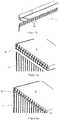
Figures 1a to 1d are perspective, top, side and end view respectively showing a storage device configured according to the present invention;Figure 2 is a perspective view showing the storage device ofFigure 1 a in which a flap door is open;Figure 3 is a perspective view showing the storage device ofFigure 1 a without the flap door;Figure 4a is a top view of a base and side wall for the storage device ofFigure 1 a in a collapsed configuration;Figure 4b is a magnified section view of the side wall connection means ofFigure 4a ;Figure 4c is a magnified section view of the side wall stabilisation means of the storage device ofFigure 4a in a collapsed configuration;Figure 4d is a magnified section view of the side wall stabilisation means ofFigure 4c in the expanded configuration;Figures 5a to 5c are side and end views respectively of the storage device ofFigure 4a in which the base and side wall are in an expanded configuration;Figures 5d to 5f are bottom, top and front views respectively of the storage device ofFigure 4a in which the base and side wall are in an expanded configuration;Figure 5g is a perspective view ofFigure 4a in which the base and side wall are in an expanded configuration;Figure 6a is a perspective view of a cover frame for the storage device shown inFigure 1 ;Figure 6b is a magnified sectional view of the connections used for supporting a stacked configuration of storage devices in a preferred embodiment of the invention extending from the cover frame ofFigure 6a ;Figure 7 is an underside view showing the cover frame ofFigure 6a ;Figures 8a and 8b are a front view and side view respectively showing the flap door;Figure 8c is a front view of the flap door ofFigures 8a and 8b held in position by the cover frame ofFigure 1 ;Figure 8d is a magnified perspective sectional view of the guide means of the cover frame for supporting the flap door ofFigures 8a and 8b ;Figure 9 is a perspective view of a pair of interconnected sealing frame units of adjacent storage devices;Figures 10 and 11 are perspectives view of the storage device ofFigure 1 showing a locking means of the present invention;Figures 12a and 12b are perspective views of an aeration chamber suitable for use with the storage device ofFigure 1 ;Figures 13a to 13c are perspective views showing alternative means of securing the cover frame to the side wall of the storage device;Figure 14 is a perspective view showing mouldedposts 38 provided in the cover frame or side walls of the storage device;Figure 15 shows a plurality of offsetchannels 40 in the cover frame8 of the storage device;Figures 16a and 16b are perspective views showing a wave or undulating link between the cover frame and side walls of the storage device, andFigure 17 is a perspective view of a storage device having a side wall and cover frame with undulating surfaces.- Referring to the drawings, and initially to
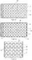
Figures 1 to 5g , there is shown a storage device formed as a container, indicated generally by thereference numeral 1, configured according to the invention. Thecontainer 1 may be made from sheet material, corrugated material, extruded moulded plastics, vacuum, roto or blow moulded plastics, cardboard and hybrid materials. A storage system comprising a plurality of thecontainers 1 stacked on top of each and connected in a side by side fashion is also envisaged in a further aspect of the present invention. - The container comprises a base or
planar section 3 and aside wall 4. For the purposes of describing this embodiment of the invention, the terms base and planar section are used interchangeably. In the embodiment shown, theside wall 4 comprisesseparate wall sections base 3 so that thecontainer 1 is movable between a collapsed configuration, as shown inFigure 4a , in which thecontainer 1 is substantially flat, and an expanded configuration, as shown inFigures 5a to 5g . In the expanded configuration there is a top opening, indicated generally by thereference numeral 5, and a front opening, indicated generally by thereference numeral 6, to theinterior 7 of thecontainer 1. - Additional internal support connections and clips are provided to lock the
side walls base 3 for added stability, strength and rigidity.Separate wall sections tab 410 which is inserted into amatching opening 420 as shown specifically inFigures 4b and 5a to 5c. Theopening 420 is sized and shaped to provide a resistance fit fortab 410. - The
base 3 may optionally comprises ground engaging feet, casters or other means for enabling thecontainer 1 to be easily moved along the ground. The ground engaging feet may be formed byprotrusions 14 formed in thebase 3. Such a feature ensures thebase 3 is elevated from the floor whilst also minimises surface contact and tension which allows smooth and easy movement on floor surfaces, such as wood, carpet, tiles and the like. - In the instance shown, the
base 3,side wall 4 and the cover frame8 comprises an array or arrangement ofprotrusions 9. Each of the protrusions on theside wall 4 comprise a plurality of ventingapertures 10 which face in and upward direction. This protects the ventilation system from downward fall of damp air and dust. The ventingapertures 10 allow for air flow through the container to prevent the retention and build up of odours during storage of articles. The location and orientation of the ventingapertures 10 allows the passage of air through thecontainer 1 but prevents the direct fall of dust from entering the container. In the instance shown, further ventingapertures 100 are arranged on an interior surface of the base. The thermal-driven warmer cleaner air rises allowing the dehumidifying, antifungal, antibacterial and deodorising flow of air to protect and condition stored articles, such as shoes. - The
base 3 of thecontainer 1 comprisesconnection holes 15a for receiving protrusions 15 (as shown inFigure 6b ) from acover frame 8 of another container to facilitate secure stacking. - Referring specifically to
Figures 4c and 4d , the side wall stabilizing means 50 comprisingsupport legs 51 are shown. Thesupport legs 51 are attached to theside wall 4 such that they project perpendicularly from the plane of theside wall 4. Accordingly when theside wall 4 moves from the collapsed substantially flat configuration into the expanded configuration the base 51 a of thesupport legs 51 abuts the planar section orbase 3 of thecontainer 1 thereby preventing theside wall 4 from folding into theinterior 7 of thecontainer 1. - The storage device also comprises a
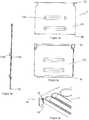
removable cover frame 8, shown inFigures 6a, 6b and7 , for closing thetop opening 5. Thecover frame 8 is a substantially rigid structure which is securable to thesidewall 4 to form a rigid enclosed box. The cover frame comprises atop wall 16 and a downwardly projectingskirt 17. - When in the collapsed configuration, the
base 3 andsidewall 4 are adapted to be contained within thecover frame 8. Thecover frame 8 is thus designed and constructed to hold theside wall 4 rigidly when erected. It is also designed to hold and stack onecontainer 1 on top of another. Thecover frame 8 may also have a duel purpose as a frame to hold the sides rigidly and also have a detachable top/cover frame built within it. Guide means 60 are provided on top of thecover frame 8 which may be used to drop a clear envelope to hold photos or information on the product in thecontainer 1. - The cover frame8 comprises side connectors, indicated generally by the
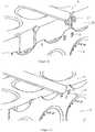
reference numeral 12, for securing the cover frame of one storage device to a cover frame of an adjacent storage device (as shown inFig. 9 ). In the instance shown, theconnectors 12 are tongue and groove type connectors so that thetongue 12a engages in a complimentary indent orgroove 12b in acover frame 8 of anadjacent storage device 1 forming a storage system. - The
container 1 also comprises a closable flap ordoor 11 which provides access to theinterior 7 of thecontainer 1 through thefront opening 6 when the container is in the expanded configuration. Such a configuration allows retrieval and placement of storage articles in the storage device without disturbing other storage devices when in a stacked configuration. - Referring now to
Figures 8a to 8d , there is shown side closing means formed as a flap or door, indicated generally by thereference numeral 11. Thedoor 11 comprises a predominantlyplanar door portion 110 projecting from a cylindrical portion orbar 112. Theplanar door portion 110 is sized and shaped such that it can be slotted into guide means 60 of thecover frame 8. Guide means 60 comprises a pair of spaced apart hooks 61 and corresponding stop means 62. The cylindrical portion or bar 112 is placed intohooks 61. Stop means 62 prevent the cylindrical portion or bar 112 from moving out of thehooks 61, however sufficient play is provided within the guide means 60 to allow thebar 112 to move or rotate freely about the longitudinal cylindrical axis. Door 11 is further provided with ahandle 114 and latching means 116. In the embodiment shown, handle 114 is formed in twosections planar door portion 110. There is an opening between the first andsecond sections door 11. Thebase 3 is provided with alip 3a. Latching means 116 seats securely behindlip 3a and cannot be moved from this position without the application of an external force. Application of an external force liftsdoor 11 slightly which enables the latching means 116 to overcomelip 3a thus freeingdoor 11 is allowing it freely rotate about thecylindrical bar 112.- As shown in
Figures. 10 and 11 locking means, indicated generally by thereference numeral 20, is provided for securing thecover frame 8 to thesidewall 4 so as to close the top opening of thecontainer 1. The locking means 20 comprises lockingteeth 21 which in the instance shown are provided on thecover frame 8, and complimentary locking indents 22 formed in thesidewall 4. The lockingteeth 21 are thus adapted for secure engagement in the locking indents 22. The use of such a locking means ensures that the cover frame may effectively clip to thecontainer 1 to form a rigid storage device. The construction of the storage device is such that the side wall can be warped or stressed when fitting the cover frame using the locking means 20 so that when secured the cover frame and side wall are of a sound rigid construction. - The
container 1 is preferably constructed from transparent material, although it will be understood that the container may be made of opaque, or any type of material as required or as desired. Thecontainer 1 may be used to store a variety of products, including, but not limited to footwear. - The present invention thus provides a modular storage solution built up from number of
containers 1 in which eachcontainer 1 may be connected to the other to form a network of pigeon holes. Eachcontainer 1 is collapsible so that it can be folded to create a compact unit for transporting. Eachcontainer 1 can be accessed through the flapfront door 11 for ease of loading and unloading. The protrusions/undulations 9 in theside walls 4 andplanar section 3 contain a system ofholes 10 that facilitates the flow of air. This flow of air is designed to prevent the retention and build up of odours when stored. The location and orientation of theholes 10 allows the passage of air but prevents the direct fall of dust from entering thecontainer 1. The design of thecontainer 1 can be in two or three parts comprisingcover frame 8 which clips to theplanar section 3 andside walls 4 to form a rigid enclosed box. The front flap ordoor 11 can be a separate component that clips to thecover frame 8,planar section 3 and orside walls 4 making a three piece construction. - The construction of the
cover frame 8 is such that theplanar section 3 andside walls 4 can be warped by the action of fitting causing stresses in the sides that make the construction more rigid. Thecontainer 1 is also insect resistant. The ventingstructures 10 are arranged in theprotrusions 9 so that the venting surfaces are predominantly on the up sloped surface regions. The unique landscape of the half-moon and other venting positions ensure that these vents are on the inside of the container and face in an upward direction. This protects the ventilation system from downward fall of damp air and dust. The thermal-driven warmer cleaner air rises allowing the dehumidifying, antifungal, antibacterial and deodorising flow of air to protect and condition the shoes. The cover frame8 can also have a top opening feature if required. Thecontainer 1 can be constructed so that it comprises material having an ultraviolet tint for the protection of product. Thecover frame 8 is designed to create sideways forces that keep sides stiff and erect. Thecover frame 8 will have catch points inside the rim to hold box above or below if used in reverse. - A useful function of the present invention is thus that it allows visible identification of the products inside. The
container 1 can be nested, stacked or folded. The use of transparent plastic and the ability to retrieve and store shoes and other products without destacking the boxes is also advantageous. The container will be available in a number of sizes to fit all types and sizes of shoe wear or other stored articles. - With reference to
Figures 12a and 12b , there is shown a tray ordrawer 30 for inserting on thebase 3 of thestorage device 1 to form a type of aeration chamber. In the instance shown, thetray 30 is raised above the internal surface of thebase 3 to form a gap therebetween. Thetray 30 comprisesholes 32, which may be optionally clustered, and be located above theground engaging protrusions 14 in thebase 3. This feature may also be used independently of thestorage device 1. Use of thetray insert 30 creates an enhanced air chamber under the shoe or product that is stored in thestorage device 1. The extra natural air flow created by this chamber allows for the dissipation of odours, greater dehumidifying, anti-fungal/bacterial and drying properties for stored products. It allows the introduction of substances for air treatment into the chamber. These substances are isolated or physically separated from the stored product. Substances including pot pouri, perfume, airfreshner, other fragrance products, anti fungal, antibacterial, insect repellent, dehumidifying or any other product care substances can be placed in the under thetray 30 as required. - With reference to
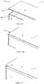
Figures 13a to 13c , thecover frame 8 and/orbase 3 may haveholes 34 in it to allow the introduction offixings 35, including plastics, screws, nails and the like to be inserted through thecover frame 8 and into corresponding receivingholes 36 locating insides walls 4 of thestorage device 1. Such a feature will provide added rigidity to theside walls 4. As shown inFigure 15 , moldedposts 38 may also project from the cover frame8, thebase 3 orside wall 4 to provide a male/female catch point or linking of the sealing frame unit/base and side wall. This feature is particularly useful if using corrugated plastic or cardboard sides. Further rigidity may also be provided by a plurality of offsetchannels 40 in thecover frame 8, as shown inFigure 15 . Still further rigidity may be provided using a wave or undulatinglink 42 between thecover frame 8 andsides 4, as shown inFigure 16a and 16b . - In an alternative embodiment, and as shown in
Figure 17 , theside walls 4 andcover frame 8 may compriseundulations 46 to thereby impart a corrugated look to thestorage device 1.
Claims (6)
- A storage device which is a two-part container (1) comprising a cover frame (8) which clips to a planar section (3) and side walls (4) to form a rigid enclosed box, wherein the side walls (4) are pivotably joined to the planar section (3) so that the container (1) is movable between a collapsed configuration in which the container (1) is substantially flat, and an expanded configuration defining an opening (5) to an interior of the container (1), and
locking means (20) for securing the cover frame (8) to the side wall (4) so as to close the opening (5) of the container (1)
whereby the locking means (20) comprises a locking portion (21) formed on one of the cover frame (8) and the side wall (4), and a locking indent (22) formed on one of the other of the cover frame (8) and the side wall (4), the locking portion (21) adapted for secure engagement in the locking indent (22)
, wherein the cover frame (8) comprises a downwardly projecting skirt (17), and one of the locking portion (21) and the locking indent (22) is on the skirt (17) and the other of the locking portion (21) and the locking indent (22) is on the side wall (4) of the container
, wherein the locking means (20) comprises a plurality of locking portions (21) formed on one of the cover frame (8) and the side wall (4), and a plurality of locking indents (22) formed in the other of the cover frame (8) and the side wall (4), the locking portions (21) are adapted for secure engagement in the locking indents (22),
wherein the locking portion (21) and locking indent (22) are of complimentary shape to facilitate secure engagement of the locking portion (21) within the locking indent (22),
wherein the side wall (4) of the container is provided with side wall connection means (400),
wherein the cover frame (8) comprises side connectors (12) for securing the cover frame (8) to a cover frame (8) of an adjacent storage device, wherein the planar section (3) of the container (1) comprises connection holes (15a) for receiving protrusions (15) extending from a cover frame (8) of another storage device to facilitate secure stacking. - A storage device as claimed in Claim 1, wherein the connectors (12) are tongue (12a) and groove (12b) type connectors.
- A storage device as claimed in Claim 1 or Claim 2, wherein the cover frame (8) further comprises an upwardly projecting collar which is configured to enable a further storage device to seat within the collar portion.
- A storage device as claimed in any one of Claims 1 to 3, wherein the locking means (20) comprises four pairs of locking portions (21) formed on one of the cover frame (8) and the side wall (4), and four pairs of locking indents (22) formed in the other of the cover frame (8) and the side wall (4), the locking portions (21) are adapted for secure engagement in the locking indents (22).
- A storage device as claimed in any one of the preceding Claims, wherein the storage device is made from one or more of sheet material, corrugated material, extruded moulded plastics, vacuum, roto or blow moulded plastics, cardboard and hybrid materials.
- A storage system comprising a plurality of storage devices configured according to any one of Claims 1 to 5.
Applications Claiming Priority (3)
| Application Number | Priority Date | Filing Date | Title |
|---|---|---|---|
| IE20090539AIES20090539A2 (en) | 2009-07-15 | 2009-07-15 | A storage device and storage system |
| US22633509P | 2009-07-17 | 2009-07-17 | |
| PCT/EP2010/060253WO2011006976A2 (en) | 2009-07-15 | 2010-07-15 | A storage device and storage system |
Publications (2)
| Publication Number | Publication Date |
|---|---|
| EP2454160A2 EP2454160A2 (en) | 2012-05-23 |
| EP2454160B1true EP2454160B1 (en) | 2016-12-28 |
Family
ID=43447235
Family Applications (1)
| Application Number | Title | Priority Date | Filing Date |
|---|---|---|---|
| EP10739878.6ANot-in-forceEP2454160B1 (en) | 2009-07-15 | 2010-07-15 | A storage device and storage system |
Country Status (7)
| Country | Link |
|---|---|
| US (1) | US9382032B2 (en) |
| EP (1) | EP2454160B1 (en) |
| JP (1) | JP5758890B2 (en) |
| CN (1) | CN102405177A (en) |
| CA (1) | CA2804822A1 (en) |
| IE (1) | IES20090539A2 (en) |
| WO (1) | WO2011006976A2 (en) |
Families Citing this family (23)
| Publication number | Priority date | Publication date | Assignee | Title |
|---|---|---|---|---|
| IES20090539A2 (en) | 2009-07-15 | 2011-01-19 | Joseph Patrick Kelly | A storage device and storage system |
| CN102390618A (en)* | 2011-07-29 | 2012-03-28 | 苏州展华纺织有限公司 | Novel tie storage box |
| US9119490B1 (en) | 2014-02-07 | 2015-09-01 | GetMugShot, Inc. | Clip on shot glasses and clip on pockets |
| USD727107S1 (en) | 2014-02-28 | 2015-04-21 | GetMugShot, Inc. | Clip on shot glass |
| US9724819B2 (en)* | 2015-02-23 | 2017-08-08 | Robert Barry | Modular interlocking containers and systems thereof |
| KR200477502Y1 (en)* | 2015-03-05 | 2015-06-16 | 이봉성 | Arranger for desk |
| CN104960737A (en)* | 2015-05-08 | 2015-10-07 | 黄永怀 | Two-layer storage box |
| US11229497B2 (en)* | 2016-02-09 | 2022-01-25 | Exactech, Inc. | Adaptable medical tray |
| KR101663745B1 (en)* | 2016-07-27 | 2016-10-10 | 주식회사 로이첸 | Collecting clothes apparatus |
| JP1599373S (en)* | 2017-04-03 | 2018-03-12 | ||
| GB2562303B (en)* | 2017-05-12 | 2019-10-16 | Crep Protect Ltd | Display crate and kit of parts therefor |
| USD911285S1 (en)* | 2017-05-23 | 2021-02-23 | Jaguar Land Rover Limited | Battery cell housing honeycomb |
| AT519989A1 (en)* | 2017-06-01 | 2018-12-15 | Fries Planungs Und Marketinggesellschaft M B H | Box, in particular for the storage and / or transport of crockery |
| US11591130B1 (en) | 2020-05-21 | 2023-02-28 | Michael Avila | Stackable and foldable box |
| CN111717505A (en)* | 2020-07-01 | 2020-09-29 | 夏枫 | Storage that can be automatic drying is with transporting goods shelves and processing equipment thereof |
| US12319466B2 (en) | 2021-05-18 | 2025-06-03 | Gerresheimer Glas Gmbh | Transporting packaging units |
| CA3159224A1 (en) | 2021-05-18 | 2022-11-18 | Gerresheimer Glas Gmbh | Transporting packaging units |
| CN114715519A (en)* | 2022-04-22 | 2022-07-08 | 颜红印 | Storage device for food detection samples |
| CN115367285B (en)* | 2022-09-23 | 2024-08-13 | 深圳市湘凡科技有限公司 | Storage box for multi-class docking station |
| CN120018998A (en)* | 2022-10-10 | 2025-05-16 | 恩特格里斯公司 | Storage containers for freezing, thawing and transport |
| USD993824S1 (en)* | 2023-04-28 | 2023-08-01 | Ze Zhang | Flower vase |
| US12194905B1 (en)* | 2023-11-15 | 2025-01-14 | Timothy Charles Bonerb | Bulk handling, loading and dumping system |
| CN118083327B (en)* | 2024-04-29 | 2024-06-21 | 阳信华胜清真肉类有限公司 | A meat product transport container that is easy to clean |
Family Cites Families (34)
| Publication number | Priority date | Publication date | Assignee | Title |
|---|---|---|---|---|
| US1407688A (en)* | 1919-04-08 | 1922-02-28 | George R Banton | Container |
| JPS5322207Y2 (en)* | 1973-10-01 | 1978-06-09 | ||
| JPS5186283U (en)* | 1974-12-27 | 1976-07-10 | ||
| US4170313A (en)* | 1977-12-29 | 1979-10-09 | Caves Robert B | Box and blank for forming the box |
| JPH041060Y2 (en)* | 1986-05-23 | 1992-01-14 | ||
| US4848618A (en) | 1988-02-16 | 1989-07-18 | Industrial Technology Research Institute | Collapsible container |
| USD325278S (en) | 1989-03-17 | 1992-04-07 | Van Der Vlies Gerardus J | Foldable container |
| JPH0484135U (en)* | 1990-11-30 | 1992-07-22 | ||
| US5501354A (en)* | 1992-05-26 | 1996-03-26 | Stromberg; Per S. | Collapsible container |
| JPH0653432U (en)* | 1992-08-13 | 1994-07-22 | 注 錫 柳 | Container with door |
| JPH0665224U (en)* | 1993-02-15 | 1994-09-13 | 不動技研株式会社 | Storage case for organization |
| USD353714S (en) | 1993-03-15 | 1994-12-27 | Stromberg Per S | Collapsible storage bin |
| USD355073S (en) | 1993-04-16 | 1995-02-07 | Satria Junaedi | Collapsible storage bin |
| FR2715373B1 (en)* | 1994-01-24 | 1996-04-05 | Robert Bourjala | Plastic crate. |
| US5676251A (en)* | 1994-08-22 | 1997-10-14 | The Coca-Cola Company | Food service kit and method for using |
| AU128271S (en) | 1995-10-18 | 1996-10-10 | Perstorp Ab | Collapsible container |
| US5829595A (en)* | 1997-03-03 | 1998-11-03 | Trienda Corporation | Thin sheet thermoformed pallet sleeve |
| JP3045579U (en)* | 1997-07-24 | 1998-02-03 | 志文 鍾 | CD storage box that can be connected vertically and horizontally |
| USD413439S (en) | 1998-03-16 | 1999-09-07 | A & J Industries, Inc. | Shipping case |
| JP3064866U (en)* | 1999-06-14 | 2000-01-28 | 淑 惠 莊 | Assembling storage case |
| US6349877B1 (en)* | 2000-09-08 | 2002-02-26 | Bradford Company | Tote box with corner enhancers and multiple piece top rail |
| USD442779S1 (en) | 2000-11-10 | 2001-05-29 | Rehrig Pacific Company | Crate for bottles |
| JP4464074B2 (en)* | 2003-06-04 | 2010-05-19 | フジコーワ工業株式会社 | Folding container |
| CN2635587Y (en)* | 2003-06-06 | 2004-08-25 | 丁朝阳 | Transparent lateral opening shoe box |
| EP1666366A4 (en)* | 2003-09-18 | 2008-09-03 | Yoshihisa Huruta | Article storage case |
| US7156249B2 (en)* | 2004-04-09 | 2007-01-02 | The United States Of America As Represented By The Secretary Of The Navy | Container, and related methods |
| WO2006064527A1 (en)* | 2004-12-17 | 2006-06-22 | Evoluzione S.R.L. | Stackable front-opening box |
| US8152014B2 (en)* | 2005-04-11 | 2012-04-10 | Paul J. Elstone, Sr. | Collapsible container system |
| USD537249S1 (en) | 2005-06-24 | 2007-02-27 | It's Academic Of Illinois, Inc. | Storage cube |
| USD553858S1 (en) | 2006-02-09 | 2007-10-30 | Odesa Gelistirilmis Polimer Yatirimlari Ve Dis Ticaret Anonim Sirketi | Foldable crate |
| US20070210083A1 (en) | 2006-03-10 | 2007-09-13 | Shih-Wei Li | Foldable basket |
| US7861879B2 (en) | 2008-05-02 | 2011-01-04 | Orbis Corporation | Folding container |
| USD594232S1 (en) | 2008-06-09 | 2009-06-16 | Wyse Steven J | Transportable and stackable storage container |
| IES20090539A2 (en) | 2009-07-15 | 2011-01-19 | Joseph Patrick Kelly | A storage device and storage system |
- 2009
- 2009-07-15IEIE20090539Apatent/IES20090539A2/ennot_activeIP Right Cessation
- 2010
- 2010-07-15EPEP10739878.6Apatent/EP2454160B1/ennot_activeNot-in-force
- 2010-07-15CACA2804822Apatent/CA2804822A1/ennot_activeAbandoned
- 2010-07-15WOPCT/EP2010/060253patent/WO2011006976A2/enactiveApplication Filing
- 2010-07-15CNCN2010800310900Apatent/CN102405177A/enactivePending
- 2010-07-15JPJP2012520046Apatent/JP5758890B2/ennot_activeExpired - Fee Related
- 2012
- 2012-01-12USUS13/349,037patent/US9382032B2/enactiveActive
Also Published As
| Publication number | Publication date |
|---|---|
| US9382032B2 (en) | 2016-07-05 |
| CA2804822A1 (en) | 2011-01-20 |
| EP2454160A2 (en) | 2012-05-23 |
| WO2011006976A3 (en) | 2011-03-31 |
| JP5758890B2 (en) | 2015-08-05 |
| CN102405177A (en) | 2012-04-04 |
| WO2011006976A2 (en) | 2011-01-20 |
| US20120211492A1 (en) | 2012-08-23 |
| JP2012532814A (en) | 2012-12-20 |
| IES20090539A2 (en) | 2011-01-19 |
Similar Documents
| Publication | Publication Date | Title |
|---|---|---|
| EP2454160B1 (en) | A storage device and storage system | |
| US5924572A (en) | Containers | |
| PL195589B1 (en) | Package | |
| US7243815B2 (en) | Thermoformed package | |
| WO2003026985A1 (en) | Footwear package | |
| US20150001120A1 (en) | Storage container and system | |
| US20080251526A1 (en) | Modular storage bin | |
| CA3043780A1 (en) | Containers featuring improved food integrity and takeout experience | |
| KR100850876B1 (en) | Strawberry packing box | |
| US20170253378A1 (en) | Nestable hamper with multi-segmented lid | |
| ES2748601T3 (en) | Takeaway pizza kit | |
| EP1780045A2 (en) | Card file | |
| US20030173359A1 (en) | Storage container for elongate articles | |
| US4930735A (en) | Bag apparatus for supporting plastic bags and the like | |
| KR102248463B1 (en) | Pizza packaging container | |
| IE20090539U1 (en) | A storage device and storage system | |
| IES85750Y1 (en) | A storage device and storage system | |
| EP2944581A1 (en) | A lid and a storage system | |
| ES2616080T3 (en) | A storage device and storage system | |
| JP3896547B2 (en) | How to sell vegetable containers and fresh vegetables | |
| ES2277726B1 (en) | TRAY FOR PRE-PACKAGING IN CARTON WITH LID. | |
| US20250320048A1 (en) | Box for transporting, displaying and serving food | |
| KR200425395Y1 (en) | Salted Fish Packaging Box | |
| JP3342682B2 (en) | Mainly plastic egg containers for business use | |
| EP0875464A1 (en) | Container and lid |
Legal Events
| Date | Code | Title | Description |
|---|---|---|---|
| PUAI | Public reference made under article 153(3) epc to a published international application that has entered the european phase | Free format text:ORIGINAL CODE: 0009012 | |
| 17P | Request for examination filed | Effective date:20120215 | |
| AK | Designated contracting states | Kind code of ref document:A2 Designated state(s):AL AT BE BG CH CY CZ DE DK EE ES FI FR GB GR HR HU IE IS IT LI LT LU LV MC MK MT NL NO PL PT RO SE SI SK SM TR | |
| DAX | Request for extension of the european patent (deleted) | ||
| REG | Reference to a national code | Ref country code:HK Ref legal event code:DE Ref document number:1170992 Country of ref document:HK | |
| 17Q | First examination report despatched | Effective date:20140722 | |
| GRAP | Despatch of communication of intention to grant a patent | Free format text:ORIGINAL CODE: EPIDOSNIGR1 | |
| RIC1 | Information provided on ipc code assigned before grant | Ipc:B65D 5/68 20060101ALI20160621BHEP Ipc:B65D 5/30 20060101AFI20160621BHEP Ipc:B65D 5/42 20060101ALI20160621BHEP Ipc:B65D 6/24 20060101ALI20160621BHEP Ipc:B65D 85/18 20060101ALI20160621BHEP | |
| INTG | Intention to grant announced | Effective date:20160722 | |
| GRAS | Grant fee paid | Free format text:ORIGINAL CODE: EPIDOSNIGR3 | |
| GRAA | (expected) grant | Free format text:ORIGINAL CODE: 0009210 | |
| AK | Designated contracting states | Kind code of ref document:B1 Designated state(s):AL AT BE BG CH CY CZ DE DK EE ES FI FR GB GR HR HU IE IS IT LI LT LU LV MC MK MT NL NO PL PT RO SE SI SK SM TR | |
| REG | Reference to a national code | Ref country code:GB Ref legal event code:FG4D | |
| REG | Reference to a national code | Ref country code:CH Ref legal event code:EP | |
| REG | Reference to a national code | Ref country code:AT Ref legal event code:REF Ref document number:857040 Country of ref document:AT Kind code of ref document:T Effective date:20170115 | |
| REG | Reference to a national code | Ref country code:IE Ref legal event code:FG4D | |
| REG | Reference to a national code | Ref country code:DE Ref legal event code:R096 Ref document number:602010039152 Country of ref document:DE | |
| PG25 | Lapsed in a contracting state [announced via postgrant information from national office to epo] | Ref country code:LV Free format text:LAPSE BECAUSE OF FAILURE TO SUBMIT A TRANSLATION OF THE DESCRIPTION OR TO PAY THE FEE WITHIN THE PRESCRIBED TIME-LIMIT Effective date:20161228 | |
| REG | Reference to a national code | Ref country code:LT Ref legal event code:MG4D | |
| PG25 | Lapsed in a contracting state [announced via postgrant information from national office to epo] | Ref country code:LT Free format text:LAPSE BECAUSE OF FAILURE TO SUBMIT A TRANSLATION OF THE DESCRIPTION OR TO PAY THE FEE WITHIN THE PRESCRIBED TIME-LIMIT Effective date:20161228 Ref country code:SE Free format text:LAPSE BECAUSE OF FAILURE TO SUBMIT A TRANSLATION OF THE DESCRIPTION OR TO PAY THE FEE WITHIN THE PRESCRIBED TIME-LIMIT Effective date:20161228 Ref country code:GR Free format text:LAPSE BECAUSE OF FAILURE TO SUBMIT A TRANSLATION OF THE DESCRIPTION OR TO PAY THE FEE WITHIN THE PRESCRIBED TIME-LIMIT Effective date:20170329 Ref country code:NO Free format text:LAPSE BECAUSE OF FAILURE TO SUBMIT A TRANSLATION OF THE DESCRIPTION OR TO PAY THE FEE WITHIN THE PRESCRIBED TIME-LIMIT Effective date:20170328 | |
| REG | Reference to a national code | Ref country code:NL Ref legal event code:MP Effective date:20161228 | |
| REG | Reference to a national code | Ref country code:AT Ref legal event code:MK05 Ref document number:857040 Country of ref document:AT Kind code of ref document:T Effective date:20161228 | |
| PG25 | Lapsed in a contracting state [announced via postgrant information from national office to epo] | Ref country code:HR Free format text:LAPSE BECAUSE OF FAILURE TO SUBMIT A TRANSLATION OF THE DESCRIPTION OR TO PAY THE FEE WITHIN THE PRESCRIBED TIME-LIMIT Effective date:20161228 Ref country code:FI Free format text:LAPSE BECAUSE OF FAILURE TO SUBMIT A TRANSLATION OF THE DESCRIPTION OR TO PAY THE FEE WITHIN THE PRESCRIBED TIME-LIMIT Effective date:20161228 | |
| REG | Reference to a national code | Ref country code:ES Ref legal event code:FG2A Ref document number:2616080 Country of ref document:ES Kind code of ref document:T3 Effective date:20170609 | |
| PG25 | Lapsed in a contracting state [announced via postgrant information from national office to epo] | Ref country code:NL Free format text:LAPSE BECAUSE OF FAILURE TO SUBMIT A TRANSLATION OF THE DESCRIPTION OR TO PAY THE FEE WITHIN THE PRESCRIBED TIME-LIMIT Effective date:20161228 | |
| REG | Reference to a national code | Ref country code:FR Ref legal event code:PLFP Year of fee payment:8 | |
| PG25 | Lapsed in a contracting state [announced via postgrant information from national office to epo] | Ref country code:RO Free format text:LAPSE BECAUSE OF FAILURE TO SUBMIT A TRANSLATION OF THE DESCRIPTION OR TO PAY THE FEE WITHIN THE PRESCRIBED TIME-LIMIT Effective date:20161228 Ref country code:SK Free format text:LAPSE BECAUSE OF FAILURE TO SUBMIT A TRANSLATION OF THE DESCRIPTION OR TO PAY THE FEE WITHIN THE PRESCRIBED TIME-LIMIT Effective date:20161228 Ref country code:EE Free format text:LAPSE BECAUSE OF FAILURE TO SUBMIT A TRANSLATION OF THE DESCRIPTION OR TO PAY THE FEE WITHIN THE PRESCRIBED TIME-LIMIT Effective date:20161228 Ref country code:CZ Free format text:LAPSE BECAUSE OF FAILURE TO SUBMIT A TRANSLATION OF THE DESCRIPTION OR TO PAY THE FEE WITHIN THE PRESCRIBED TIME-LIMIT Effective date:20161228 Ref country code:IS Free format text:LAPSE BECAUSE OF FAILURE TO SUBMIT A TRANSLATION OF THE DESCRIPTION OR TO PAY THE FEE WITHIN THE PRESCRIBED TIME-LIMIT Effective date:20170428 | |
| PG25 | Lapsed in a contracting state [announced via postgrant information from national office to epo] | Ref country code:BG Free format text:LAPSE BECAUSE OF FAILURE TO SUBMIT A TRANSLATION OF THE DESCRIPTION OR TO PAY THE FEE WITHIN THE PRESCRIBED TIME-LIMIT Effective date:20170328 Ref country code:BE Free format text:LAPSE BECAUSE OF FAILURE TO SUBMIT A TRANSLATION OF THE DESCRIPTION OR TO PAY THE FEE WITHIN THE PRESCRIBED TIME-LIMIT Effective date:20161228 Ref country code:AT Free format text:LAPSE BECAUSE OF FAILURE TO SUBMIT A TRANSLATION OF THE DESCRIPTION OR TO PAY THE FEE WITHIN THE PRESCRIBED TIME-LIMIT Effective date:20161228 Ref country code:SM Free format text:LAPSE BECAUSE OF FAILURE TO SUBMIT A TRANSLATION OF THE DESCRIPTION OR TO PAY THE FEE WITHIN THE PRESCRIBED TIME-LIMIT Effective date:20161228 Ref country code:PL Free format text:LAPSE BECAUSE OF FAILURE TO SUBMIT A TRANSLATION OF THE DESCRIPTION OR TO PAY THE FEE WITHIN THE PRESCRIBED TIME-LIMIT Effective date:20161228 Ref country code:PT Free format text:LAPSE BECAUSE OF FAILURE TO SUBMIT A TRANSLATION OF THE DESCRIPTION OR TO PAY THE FEE WITHIN THE PRESCRIBED TIME-LIMIT Effective date:20170428 | |
| REG | Reference to a national code | Ref country code:DE Ref legal event code:R097 Ref document number:602010039152 Country of ref document:DE | |
| PLBE | No opposition filed within time limit | Free format text:ORIGINAL CODE: 0009261 | |
| STAA | Information on the status of an ep patent application or granted ep patent | Free format text:STATUS: NO OPPOSITION FILED WITHIN TIME LIMIT | |
| PG25 | Lapsed in a contracting state [announced via postgrant information from national office to epo] | Ref country code:DK Free format text:LAPSE BECAUSE OF FAILURE TO SUBMIT A TRANSLATION OF THE DESCRIPTION OR TO PAY THE FEE WITHIN THE PRESCRIBED TIME-LIMIT Effective date:20161228 | |
| 26N | No opposition filed | Effective date:20170929 | |
| PG25 | Lapsed in a contracting state [announced via postgrant information from national office to epo] | Ref country code:SI Free format text:LAPSE BECAUSE OF FAILURE TO SUBMIT A TRANSLATION OF THE DESCRIPTION OR TO PAY THE FEE WITHIN THE PRESCRIBED TIME-LIMIT Effective date:20161228 | |
| REG | Reference to a national code | Ref country code:CH Ref legal event code:PL | |
| PG25 | Lapsed in a contracting state [announced via postgrant information from national office to epo] | Ref country code:CH Free format text:LAPSE BECAUSE OF NON-PAYMENT OF DUE FEES Effective date:20170731 Ref country code:LI Free format text:LAPSE BECAUSE OF NON-PAYMENT OF DUE FEES Effective date:20170731 | |
| PG25 | Lapsed in a contracting state [announced via postgrant information from national office to epo] | Ref country code:LU Free format text:LAPSE BECAUSE OF NON-PAYMENT OF DUE FEES Effective date:20170715 | |
| REG | Reference to a national code | Ref country code:FR Ref legal event code:PLFP Year of fee payment:9 | |
| PG25 | Lapsed in a contracting state [announced via postgrant information from national office to epo] | Ref country code:MT Free format text:LAPSE BECAUSE OF NON-PAYMENT OF DUE FEES Effective date:20170715 | |
| REG | Reference to a national code | Ref country code:HK Ref legal event code:WD Ref document number:1170992 Country of ref document:HK | |
| PG25 | Lapsed in a contracting state [announced via postgrant information from national office to epo] | Ref country code:MC Free format text:LAPSE BECAUSE OF FAILURE TO SUBMIT A TRANSLATION OF THE DESCRIPTION OR TO PAY THE FEE WITHIN THE PRESCRIBED TIME-LIMIT Effective date:20161228 Ref country code:HU Free format text:LAPSE BECAUSE OF FAILURE TO SUBMIT A TRANSLATION OF THE DESCRIPTION OR TO PAY THE FEE WITHIN THE PRESCRIBED TIME-LIMIT; INVALID AB INITIO Effective date:20100715 | |
| PG25 | Lapsed in a contracting state [announced via postgrant information from national office to epo] | Ref country code:CY Free format text:LAPSE BECAUSE OF NON-PAYMENT OF DUE FEES Effective date:20161228 | |
| PG25 | Lapsed in a contracting state [announced via postgrant information from national office to epo] | Ref country code:MK Free format text:LAPSE BECAUSE OF FAILURE TO SUBMIT A TRANSLATION OF THE DESCRIPTION OR TO PAY THE FEE WITHIN THE PRESCRIBED TIME-LIMIT Effective date:20161228 | |
| PG25 | Lapsed in a contracting state [announced via postgrant information from national office to epo] | Ref country code:TR Free format text:LAPSE BECAUSE OF FAILURE TO SUBMIT A TRANSLATION OF THE DESCRIPTION OR TO PAY THE FEE WITHIN THE PRESCRIBED TIME-LIMIT Effective date:20161228 | |
| PG25 | Lapsed in a contracting state [announced via postgrant information from national office to epo] | Ref country code:AL Free format text:LAPSE BECAUSE OF FAILURE TO SUBMIT A TRANSLATION OF THE DESCRIPTION OR TO PAY THE FEE WITHIN THE PRESCRIBED TIME-LIMIT Effective date:20161228 | |
| PGFP | Annual fee paid to national office [announced via postgrant information from national office to epo] | Ref country code:IT Payment date:20220622 Year of fee payment:13 Ref country code:IE Payment date:20220620 Year of fee payment:13 | |
| PGFP | Annual fee paid to national office [announced via postgrant information from national office to epo] | Ref country code:ES Payment date:20220801 Year of fee payment:13 Ref country code:DE Payment date:20220629 Year of fee payment:13 | |
| PGFP | Annual fee paid to national office [announced via postgrant information from national office to epo] | Ref country code:FR Payment date:20220729 Year of fee payment:13 | |
| PGFP | Annual fee paid to national office [announced via postgrant information from national office to epo] | Ref country code:GB Payment date:20230727 Year of fee payment:14 | |
| REG | Reference to a national code | Ref country code:DE Ref legal event code:R119 Ref document number:602010039152 Country of ref document:DE | |
| REG | Reference to a national code | Ref country code:IE Ref legal event code:MM4A | |
| PG25 | Lapsed in a contracting state [announced via postgrant information from national office to epo] | Ref country code:DE Free format text:LAPSE BECAUSE OF NON-PAYMENT OF DUE FEES Effective date:20240201 | |
| PG25 | Lapsed in a contracting state [announced via postgrant information from national office to epo] | Ref country code:FR Free format text:LAPSE BECAUSE OF NON-PAYMENT OF DUE FEES Effective date:20230731 | |
| PG25 | Lapsed in a contracting state [announced via postgrant information from national office to epo] | Ref country code:IE Free format text:LAPSE BECAUSE OF NON-PAYMENT OF DUE FEES Effective date:20230715 | |
| PG25 | Lapsed in a contracting state [announced via postgrant information from national office to epo] | Ref country code:IT Free format text:LAPSE BECAUSE OF NON-PAYMENT OF DUE FEES Effective date:20230715 Ref country code:IE Free format text:LAPSE BECAUSE OF NON-PAYMENT OF DUE FEES Effective date:20230715 | |
| REG | Reference to a national code | Ref country code:ES Ref legal event code:FD2A Effective date:20240830 | |
| PG25 | Lapsed in a contracting state [announced via postgrant information from national office to epo] | Ref country code:ES Free format text:LAPSE BECAUSE OF NON-PAYMENT OF DUE FEES Effective date:20230716 | |
| PG25 | Lapsed in a contracting state [announced via postgrant information from national office to epo] | Ref country code:ES Free format text:LAPSE BECAUSE OF NON-PAYMENT OF DUE FEES Effective date:20230716 | |
| GBPC | Gb: european patent ceased through non-payment of renewal fee | Effective date:20240715 | |
| PG25 | Lapsed in a contracting state [announced via postgrant information from national office to epo] | Ref country code:GB Free format text:LAPSE BECAUSE OF NON-PAYMENT OF DUE FEES Effective date:20240715 |