EP2451697B1 - Device and method for adjusting the position between a front wing and a front door of a vehicle - Google Patents
Device and method for adjusting the position between a front wing and a front door of a vehicleDownload PDFInfo
- Publication number
- EP2451697B1 EP2451697B1EP10734202.4AEP10734202AEP2451697B1EP 2451697 B1EP2451697 B1EP 2451697B1EP 10734202 AEP10734202 AEP 10734202AEP 2451697 B1EP2451697 B1EP 2451697B1
- Authority
- EP
- European Patent Office
- Prior art keywords
- framework
- bodywork
- rod
- bodywork elements
- holding
- Prior art date
- Legal status (The legal status is an assumption and is not a legal conclusion. Google has not performed a legal analysis and makes no representation as to the accuracy of the status listed.)
- Not-in-force
Links
Images


Classifications
- B—PERFORMING OPERATIONS; TRANSPORTING
- B62—LAND VEHICLES FOR TRAVELLING OTHERWISE THAN ON RAILS
- B62D—MOTOR VEHICLES; TRAILERS
- B62D65/00—Designing, manufacturing, e.g. assembling, facilitating disassembly, or structurally modifying motor vehicles or trailers, not otherwise provided for
- B62D65/02—Joining sub-units or components to, or positioning sub-units or components with respect to, body shell or other sub-units or components
- B62D65/06—Joining sub-units or components to, or positioning sub-units or components with respect to, body shell or other sub-units or components the sub-units or components being doors, windows, openable roofs, lids, bonnets, or weather strips or seals therefor
Definitions
- the present inventionrelates to a device for adjusting the position between two bodywork elements of a vehicle constituted respectively of a front wing and a front door, and to a related adjustment process.
- the front winghas a rear flange which extends opposite the front edge of the front door, so that these two flanges are substantially contiguous.
- the front fender and the front doormust have a gap of predefined width and substantially constant and the front fender and the front door must be substantially coplanar at these edges.
- it is important that these two flangesare perfectly aligned in a substantially vertical direction, and that they provide a contiguous continuous surface without offset in the transverse direction Y of the vehicle.
- the present inventionaims to solve all or part of these disadvantages by providing a device that allow easy, fast and improved adjustment of the front wing relative to the front door.
- the upper connecting meansis shaped to connect together the respective upper parts of the two body members, and is thus shaped to allow adjustment in position of these two upper parts.
- the lower connecting meansis shaped to connect together the respective lower portions of the two body members, and is thus shaped to allow adjustment in position of these two lower parts.
- the sliding pinallows adjustment of the gap between the upper and lower parts of the front wing and front door respectively.
- the first anchoring memberis in the form of a protruding part of the chassis intended to be anchored in a housing formed in the first bodywork element.
- the holding meanscomprise at least two chassis holding members on the respective lower portions of the bodywork elements, said holding members, in particular made in the form of magnets, being fixed on the lower part of said frame of both sides of the first end of the stem.
- the inventionalso relates to a method for adjusting the position between two bodywork elements of a vehicle consisting respectively of a front fender and a front door, said method consisting in using the adjustment device according to the invention.
- the inventionrelates to a device 1 for adjusting the position between a front fender 2 and a front door 3 of a motor vehicle, this front fender 2 and this front door 3 constituting bodywork elements of the vehicle.
- the description of this device 1is made with reference to Figures 1 to 12 .
- upper partis understood to mean a part situated in height or elevation with respect to a “lower part” which is situated substantially at the level of the underbody of the vehicle. It is understood by "central portion” an intermediate or middle portion between the lower and upper parts.
- adjustment device 1For the following description of the adjustment device 1 according to the invention, it is understood by “front face” the face intended to come opposite the vehicle and more particularly its bodywork elements 2, 3, and it is understood by “rear face” the face opposite to the front face and therefore opposite to the vehicle when said device 1 is put in place on the vehicle in question.
- the device 1comprises means for holding the chassis 10 on the front wing 2 and the front door 3, said holding means being fixed on said frame 10 on the front side.
- the holding meansare in the form of magnets embedded in plastic envelopes to prevent the metal particles from scratching the bodywork elements.
- the plastic envelopeshave a thickness of the order of a millimeter at the surfaces of contact with the bodywork elements.
- the central magnet 43makes it possible to guarantee the outcropping of the front wing 2 with respect to the front door 3 in the central zone.
- the device 1comprises an upper connecting means 5 between the respective upper parts of the front wing 2 and the front door 3, said upper connecting means 5 being designed to adjust the position of the upper part of the front wing 2 by relative to the upper part of the front door 3, and more particularly to adjust the gap between the front wing 2 and the front door 3 and to ensure that these two body members 2, 3 provide in the upper part a contiguous continuous surface without offset in the transverse direction Y of the vehicle.
- the protruding part 51forms a finger of cylindrical section which is intended to be anchored in a notch 30 formed on the front door 3, and more particularly on the lower edge 31 of the wall delimiting the window opening 32.
- the notch 54 and the groove of the protuberance 55are oriented in the same direction and arranged facing the front door 3, once the device 1 in situation.
- the distance L along the longitudinal axis X of the vehicle, visible in figure 10 between the bottom of the notch 54 and the bottom of the groove of the protrusion 55adjusts the width of the air gap between the respective upper parts of the front door 3 and the front wing 2.
- the distance D according to the transverse axis Y of the vehicle, visible in figure 10makes it possible to adjust the coplanarity between the respective upper parts of the front door 3 and the front wing 2, in other words to ensure a continuous surface without offset in the transverse direction Y of the vehicle.
- the device 1comprises a lower connecting means 6 between the respective lower portions of the front wing 2 and the front door 3, said lower connecting means 6 being designed to adjust the position of the lower part of the front wing 2 by relative to the lower part of the front door 3, and more particularly to adjust the gap between the front wing 2 and the front door 3 and to ensure that these two body members 2, 3 provide in the lower part a contiguous continuous surface without offset in the transverse direction Y of the vehicle.
- the first end 63 of the rod 61is provided with two lateral branches bent at 90 ° and whose free ends are provided with shims 68.
- the notch 62has a longitudinal portion and a circumferential portion about a quarter turn.
- the rod 61can occupy a first so-called rest position in which its first end 63 is disposed between the two magnets 44 and 45 and does not protrude out of these magnets.
- the handle 65is adapted to move the rod 61 in translation in the support / sleeve 60, from the rest position, in a first direction illustrated by the arrow T on the figure 11 so that its first end 63 passes through the air gap separating the front door 3 and the front wing 2 at the bottom.
- the first end 63 of the rod 61is sized to cross this gap when the device 1 is in place on the vehicle by means of the magnets.
- the handle 65is further adapted to move the rod 61 in rotation in the support / sleeve 60, from the second position, at an angle of substantially 90 °, as illustrated by the arrow R in FIG. figure 12 , in order to arrange the two shims 68 of the lateral branches of the first end 63 facing respectively the front door 3 and the front wing 2. To achieve this rotation, the handle 65 engages in the circumferential portion of the notch 62 and the rod 61 thus occupies a third position visible in figure 12 .
- the spring 66is intended to impose a displacement of the rod 61 in translation in a second direction opposite to the first direction of translation. In this way, once the rod 61 occupies the third position, the spring 66 drives the rod 61 in a fourth position called final position where the two lateral branches and the wedges 68 in particular are in abutment against the two body members 2, 3 respectively. In this way, the lower connecting means 6 makes it possible to adjust the relative positioning of the two body members 2, 3 and in particular the coplanarity of the front wing 2 and the front door 3 to obtain in the lower part a contiguous continuous surface. without offset in the transverse direction Y of the vehicle.
- the dimensions of the shims 68are pre-established to refine the alignment of the front wing 2 and the front door 3.
- the hook member 690has a bevelled free end 692 so that, during assembly of the device 1, said free beveled end 692 bears against the front wing 2 and thus the hook member 690 pivots to the against spring 691 and locks on said front wing 2 as illustrated in FIGS. Figures 11 and 12 .
- the first end 63 of the rod 61serves to play the game between the front wing 2 and the front door 3 in the lower part along the longitudinal axis X; this game being guaranteed by the natural rocking by gravity of the adjusting device 1 against the front door 3, and the hook member 690 ensuring the plating of the front wing 2 against this first end 63 of the rod 61.
- the device 1also comprises a pin 70 slidably mounted on the frame 10 and intended to be inserted into the gap separating the two body members 2 and 3.
- the pin 70is fixed on a carriage 71 slidably mounted on the lower plate 13 of the chassis 10, and more particularly on a guide rail 72 fixed on this lower plate 13, in a direction substantially parallel to the longitudinal axis X of the vehicle .
- the carriage 71supports a handle 73 projecting towards the rear face of the device 1 to form a gripping means adapted to allow the user to move the carriage 71 and therefore the pin 70 to ensure the insertion of said pin 70 into the air gap.
- Such a device 1makes it possible to guarantee the geometric quality of the docking of the front fender 2 with respect to the front door 3 without offering any constraint because the use of this device 1 is made before the tightening of the fastening screws of the fender. front wing 2 on the body.
- This device 1also offers the advantage of being usable on several silhouettes or vehicle models without requiring bulky templates to store at the edge of the assembly line, with very easy and quick maintenance in the sense that it is essentially necessary to clean the magnets 41 to 45 on a regular basis.
Landscapes
- Engineering & Computer Science (AREA)
- Manufacturing & Machinery (AREA)
- Chemical & Material Sciences (AREA)
- Combustion & Propulsion (AREA)
- Transportation (AREA)
- Mechanical Engineering (AREA)
- Power-Operated Mechanisms For Wings (AREA)
- Body Structure For Vehicles (AREA)
- Automobile Manufacture Line, Endless Track Vehicle, Trailer (AREA)
- Straightening Metal Sheet-Like Bodies (AREA)
Description
Translated fromFrenchLa présente invention se rapporte à un dispositif de réglage de la position entre deux éléments de carrosserie d'un véhicule constitués respectivement d'une aile avant et d'une porte avant, et à un procédé de réglage associé.The present invention relates to a device for adjusting the position between two bodywork elements of a vehicle constituted respectively of a front wing and a front door, and to a related adjustment process.
Le document
De façon classique sur un véhicule automobile, l'aile avant présente un rebord arrière qui s'étend en regard du rebord avant de la porte avant, de sorte que ces deux rebords sont sensiblement jointifs. Pour des raisons évidentes d'esthétisme, l'aile avant et la porte avant doivent présenter un entrefer de largeur prédéfinie et sensiblement constante et l'aile avant et la porte avant doivent être sensiblement coplanaires au niveau de ces rebords. Autrement dit, il est important que ces deux rebords soient parfaitement alignés selon une direction sensiblement verticale, et qu'ils offrent une surface continue jointive sans décalage dans la direction transversale Y du véhicule.In a conventional manner on a motor vehicle, the front wing has a rear flange which extends opposite the front edge of the front door, so that these two flanges are substantially contiguous. For obvious reasons of aesthetics, the front fender and the front door must have a gap of predefined width and substantially constant and the front fender and the front door must be substantially coplanar at these edges. In other words, it is important that these two flanges are perfectly aligned in a substantially vertical direction, and that they provide a contiguous continuous surface without offset in the transverse direction Y of the vehicle.
Sur les lignes de montage des véhicules automobiles se présentent une certaine difficulté dans le réglage de position de l'aile avant par rapport à la porte avant ; ladite porte avant étant généralement monté sur le châssis du véhicule avant l'aile avant. La difficulté porte essentiellement sur le réglage de l'entrefer et de la coplanarité entre la porte avant et l'aile avant.On the assembly lines of motor vehicles there is some difficulty in adjusting the position of the front fender relative to the front door; said front door being generally mounted on the chassis of the vehicle before the front fender. The difficulty is essentially the adjustment of the air gap and the coplanarity between the front door and the front fender.
Pour le montage de l'aile avant sur le châssis, il est connu d'employer des outils suspendus qui sont montés sur des rails disposés en hauteur au-dessus des lignes de montage et qui supportent les ailes avant pour régler leur accostage sur le châssis du véhicule et régler leur positionnement par rapport à la porte avant. Néanmoins, de tels outils présentent de nombreux inconvénients comme par exemple leur encombrement, leur difficulté de manipulation, les risques de collision entre l'outil et le véhicule.For the mounting of the front fender on the chassis, it is known to use suspended tools which are mounted on rails arranged in height above the assembly lines and which support the front fenders to adjust their docking on the chassis of the vehicle and adjust their position relative to the front door. However, such tools have many disadvantages such as their size, their handling difficulty, the risk of collision between the tool and the vehicle.
La présente invention a pour but résoudre en tout ou partie ces inconvénients en proposant un dispositif qui permettent un réglage aisé, rapide et amélioré de l'aile avant par rapport à la porte avant.The present invention aims to solve all or part of these disadvantages by providing a device that allow easy, fast and improved adjustment of the front wing relative to the front door.
A cet effet, elle propose dispositif de réglage de la position entre deux éléments de carrosserie d'un véhicule constitués respectivement d'une aile avant et d'une porte avant, ledit dispositif étant remarquable en ce qu'il comporte un châssis et les moyens suivants :
- au moins un moyen supérieur de liaison entre des parties supérieures respectives des deux éléments de carrosserie, ledit moyen supérieur de liaison étant monté sur une partie supérieure dudit châssis ;
- au moins un moyen inférieur de liaison entre des parties inférieures respectives des deux éléments de carrosserie, ledit moyen inférieur de liaison étant monté sur une partie inférieure dudit châssis ;
- au moins un pion monté à coulissement sur ledit châssis et destiné à être inséré dans l'entrefer séparant les deux éléments de carrosserie ; et
- des moyens de maintien du châssis sur les éléments de carrosserie respectifs, lesdits moyens de maintien, notamment réalisés sous la forme d'aimants, étant fixés sur ledit châssis.
- at least one upper link means between respective upper parts of the two body members, said upper link means being mounted on an upper portion of said frame;
- at least one lower connection means between respective lower portions of the two body members, said lower link means being mounted on a lower portion of said frame;
- at least one pin slidably mounted on said frame and intended to be inserted into the air gap separating the two bodywork elements; and
- means for holding the frame on the respective body members, said holding means, in particular made in the form of magnets, being fixed on said frame.
Ainsi, il n'est pas nécessaire de suspendre le dispositif conforme à l'invention, ce dernier supportant ces propres moyens de maintien à la fois sur l'aile avant et sur la porte avant du véhicule.Thus, it is not necessary to suspend the device according to the invention, the latter supporting these own holding means both on the front wing and on the front door of the vehicle.
Le moyen supérieur de liaison est conformé pour relier entre elles les parties supérieures respectives des deux éléments de carrosserie, et est ainsi conformé pour permettre le réglage en position de ces deux parties supérieures.The upper connecting means is shaped to connect together the respective upper parts of the two body members, and is thus shaped to allow adjustment in position of these two upper parts.
De même, le moyen inférieur de liaison est conformé pour relier entre elles les parties inférieures respectives des deux éléments de carrosserie, et est ainsi conformé pour permettre le réglage en position de ces deux parties inférieures.Similarly, the lower connecting means is shaped to connect together the respective lower portions of the two body members, and is thus shaped to allow adjustment in position of these two lower parts.
Le pion coulissant permet un réglage de l'entrefer entre les parties supérieures et inférieures des respectivement aile avant et porte avant.The sliding pin allows adjustment of the gap between the upper and lower parts of the front wing and front door respectively.
Dans une réalisation particulière, le moyen supérieur de liaison comporte :
- un organe de mise en tension, notamment du type ressort, ledit organe de mise en tension présentant une première extrémité et une deuxième extrémité ;
- un premier organe d'ancrage solidaire du châssis et destiné à être ancré sur l'un des deux éléments de carrosserie, appelé premier élément de carrosserie, ledit organe de mise en tension étant monté à sa première extrémité sur ledit premier organe d'ancrage ; et
- un second organe d'ancrage monté sur la deuxième extrémité de l'organe de mise en tension, ledit second organe d'ancrage étant destiné à être ancré sur l'autre des deux éléments de carrosserie, appelé deuxième élément de carrosserie, une fois que ledit premier organe d'ancrage est ancré sur le premier élément de carrosserie.
- a tensioning member, in particular of the spring type, said tensioning member having a first end and a second end;
- a first anchoring member secured to the frame and intended to be anchored to one of the two body members, called the first body member, said tensioning member being mounted at its first end on said first anchoring member; and
- a second anchoring member mounted on the second end of the tensioning member, said second anchoring member being intended to be anchored on the other of the two bodywork elements, called second element of body, once said first anchor member is anchored to the first body member.
Selon une caractéristique, le premier organe d'ancrage est réalisé sous la forme d'une pièce en saillie du châssis destinée à être ancrée dans un logement ménagé dans le premier élément de carrosserie.According to one characteristic, the first anchoring member is in the form of a protruding part of the chassis intended to be anchored in a housing formed in the first bodywork element.
Selon une autre caractéristique, le second organe d'ancrage comprend :
- une embase dans laquelle est ménagée une encoche destinée à coopérer avec le premier élément de carrosserie ; et
- une protubérance saillante de ladite embase et présentant une rainure destinée à coopérer avec le rebord d'un logement ménagé dans le second élément de carrosserie.
- a base in which is formed a notch for cooperating with the first body member; and
- a protuberance protruding from said base and having a groove for cooperating with the flange of a housing formed in the second body member.
Dans un mode de réalisation particulier, le moyen inférieur de liaison comporte :
- une tige montée à coulissement et à rotation dans un support de tige solidaire du châssis, ladite tige présentant une première extrémité en forme générale de « T » en étant munie de deux branches latérales ;
- un moyen de mise en mouvement de ladite tige adapté pour déplacer la tige en translation selon un premier sens afin que sa première extrémité traverse l'entrefer séparant les deux éléments de carrosserie, et pour déplacer la tige en rotation afin de disposer les deux branches latérales en regard des deux éléments de carrosserie respectifs ; et
- un moyen de rappel destiné à imposer un déplacement de la tige en translation selon un deuxième sens opposé au premier sens de sorte que les deux branches latérales viennent en butée contre les deux éléments de carrosserie respectifs pour régler le positionnement relatif des deux éléments de carrosserie.
- a rod mounted to slide and rotate in a rod support secured to the frame, said rod having a first end in the general shape of "T" being provided with two lateral branches;
- means for moving said rod adapted to move the rod in translation in a first direction so that its first end passes through the air gap separating the two body members, and to move the rod in rotation to dispose the two lateral branches facing the two respective bodywork elements; and
- a return means for imposing a displacement of the rod in translation in a second direction opposite to the first direction so that the two lateral branches abut against the two respective body members to adjust the relative positioning of the two body members.
Selon une caractéristique, les moyens de maintien comportent au moins deux organes de maintien du châssis sur les parties inférieures respectives des éléments de carrosserie, lesdits organes de maintien, notamment réalisés sous la forme d'aimants, étant fixés sur la partie inférieure dudit châssis de part et d'autre de la première extrémité de la tige.According to one characteristic, the holding means comprise at least two chassis holding members on the respective lower portions of the bodywork elements, said holding members, in particular made in the form of magnets, being fixed on the lower part of said frame of both sides of the first end of the stem.
Selon une autre caractéristique, le moyen inférieur de liaison comporte en outre :
- un organe formant crochet conçu pour verrouiller ledit châssis sur l'un des éléments de carrosserie, ledit organe formant crochet étant monté pivotant sur le châssis entre une position de déverrouillage et une position de verrouillage ; et
- un organe de rappel fixé d'une part sur l'organe formant crochet et d'autre part sur le châssis pour rappeler l'organe formant crochet en position de verrouillage.
- a hook member adapted to lock said frame to one of the body members, said hook member being pivotally mounted on the frame between an unlocking position and a locking position; and
- a return member fixed on the one hand on the hook member and on the other hand on the frame to return the hook member in the locking position.
La présente invention concerne également les caractéristiques ci après :
- le pion est fixé sur un chariot monté à coulissement sur le châssis, ledit chariot supportant un moyen de préhension adapté pour permettre le déplacement dudit chariot ; et/ou
- les moyens de maintien comportent au moins deux organes de maintien du châssis sur les parties supérieures respectives des éléments de carrosserie, lesdits organes de maintien étant fixés sur la partie supérieure dudit châssis et notamment réalisés sous la forme d'aimants.
- the pin is fixed on a carriage slidably mounted on the frame, said carriage supporting a gripping means adapted to allow the movement of said carriage; and or
- the holding means comprise at least two chassis holding members on the respective upper parts of the body members, said holding members being fixed on the upper part of said frame and in particular made in the form of magnets.
L'invention concerne également un procédé de réglage de la position entre deux éléments de carrosserie d'un véhicule constitués respectivement d'une aile avant et d'une porte avant, ledit procédé consistant à utiliser le dispositif de réglage conforme à l'invention.The invention also relates to a method for adjusting the position between two bodywork elements of a vehicle consisting respectively of a front fender and a front door, said method consisting in using the adjustment device according to the invention.
D'autres caractéristiques et avantages de la présente invention apparaîtront à la lecture de la description détaillée ci-après, d'un exemple de mise en oeuvre non limitatif, faite en référence aux figures annexées dans lesquelles :
- les
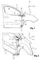
figures 1 et 2 sont des vues respectivement de côté et en perspective d'un dispositif de réglage conforme à l'invention en situation sur une aile avant et une porte avant de véhicule automobile ; - la
figure 3 est une vue en perspective arrière du dispositif de réglage visible auxfigures 1 et 2 ; - les
figures 4 à 6 sont des vues en perspectives avant détaillées des zones respectivement IV à VI de lafigure 3 ; - les
figures 7 à 9 sont des vues en perspective de la partie supérieure du dispositif de réglage desfigures 1 et 2 en situation sur une aile avant et une porte avant de véhicule automobile ; - la
figure 10 est une vue de dessus du dispositif de réglage desfigures 1 et 2 en situation sur une aile avant et une porte avant de véhicule automobile ; - les
figures 11 et 12 sont des vues en perspective de la partie inférieure du dispositif de réglage desfigures 1 et 2 en situation sur une aile avant et une porte avant de véhicule automobile, où la tige en forme de « T » du moyen inférieur de liaison occupe respectivement une position d'engagement dans l'entrefer séparant l'aile avant et la porte avant et une position de verrouillage sur l'aile avant et la porte avant.
- the
Figures 1 and 2 are views respectively from the side and in perspective of an adjusting device according to the invention in situation on a front wing and a front door of a motor vehicle; - the
figure 3 is a rear perspective view of the visible adjustment device atFigures 1 and 2 ; - the
Figures 4 to 6 are views in detailed forward perspectives of areas IV to VI respectively of thefigure 3 ; - the
Figures 7 to 9 are perspective views of the upper part of the adjustment device ofFigures 1 and 2 in situation on a front fender and a front door of a motor vehicle; - the
figure 10 is a top view of the adjustment device of theFigures 1 and 2 in situation on a front fender and a front door of a motor vehicle; - the
Figures 11 and 12 are perspective views of the lower part of the adjustment device ofFigures 1 and 2 in a situation on a front fender and a front door of a motor vehicle, where the "T" -shaped rod of the lower connecting means occupies respectively an engagement position in the air gap separating the front fender and the front door and a locking position on the front fender and the front door.
L'invention concerne un dispositif de réglage 1 de la position entre une aile avant 2 et une porte avant 3 d'un véhicule automobile, cette aile avant 2 et cette porte avant 3 constituant des éléments de carrosserie du véhicule. La description de ce dispositif 1 est faite en référence aux
Pour la suite de la description, il est entendu par « partie supérieure » une partie située en hauteur ou en élévation par rapport à une « partie inférieure » qui est située sensiblement au niveau du soubassement du véhicule. Il est entendu par « partie centrale » une partie intermédiaire ou médiane située entre les parties inférieure et supérieure.For the remainder of the description, the term "upper part" is understood to mean a part situated in height or elevation with respect to a "lower part" which is situated substantially at the level of the underbody of the vehicle. It is understood by "central portion" an intermediate or middle portion between the lower and upper parts.
Pour la suite de la description, il est entendu par « direction longitudinale du véhicule » ou « axe longitudinal du véhicule » la direction ou l'axe X s'étendant de l'arrière à l'avant du véhicule relativement à l'avancement en marche avant du véhicule, et par « direction transversale au véhicule » ou « axe transversal au véhicule » la direction ou l'axe Y s'étendant de gauche à droite de façon perpendiculaire à la direction longitudinale du véhicule.For the following description, it is understood by "longitudinal direction of the vehicle" or "longitudinal axis of the vehicle" the direction or axis X extending from the rear to the front of the vehicle relative to the advancement in forward of the vehicle, and by "transverse direction to the vehicle" or "transverse axis to the vehicle" the direction or the Y axis extending from left to right perpendicular to the longitudinal direction of the vehicle.
Pour la suite de la description du dispositif de réglage 1 conforme à l'invention, il est entendu par « face avant » la face destinée à venir en regard du véhicule et plus particulièrement de ses éléments de carrosserie 2, 3, et il est entendu par « face arrière » la face opposée à la face avant et donc opposée au véhicule quand ledit dispositif 1 est mis en place sur le véhicule en question.For the following description of the
Le dispositif 1 conforme à l'invention comporte un châssis 10 en acier comprenant :
- une poutre 11 réalisée sous la forme d'un profilé et présentant une extrémité supérieure et une extrémité inférieure ;
- un bras supérieur 12 transversal fixé à l'extrémité supérieure de la poutre 11 et incliné par rapport à la poutre 11, ledit bras étant réalisé sous la forme d'un profilé et s'étendant en direction de la
porte avant 3 une fois le dispositif 1 en situation ; - une plaque supérieure 13 plane en acier fixée sur l'extrémité supérieure de la poutre 11 côté face avant ;
- un bras inférieur 14 transversal fixé à l'extrémité supérieure de la poutre 11 et incliné par rapport à la poutre 11, ledit bras étant réalisé sous la forme d'une plaque plane et s'étendant en direction de l'aile avant 2 une fois le dispositif 1 en situation ; et
- une plaque inférieure 15 plane en acier fixée sur l'extrémité inférieure de la poutre 11 côté face avant, ladite plaque inférieure 15 étant pourvue d'un orifice traversant venant dans le prolongement d'un orifice traversant l'extrémité inférieure de la poutre 11.
- a
beam 11 in the form of a profile and having an upper end and a lower end; - a transverse
upper arm 12 fixed to the upper end of thebeam 11 and inclined relative to thebeam 11, said arm being formed in the form of a profile and extending towards thefront door 3 once thedevice 1 in situation; - a
steel top plate 13 fixed to the upper end of thebeam 11 on the front side; - a transverse
lower arm 14 fixed to the upper end of thebeam 11 and inclined relative to thebeam 11, said arm being formed in the form of a flat plate and extending towards thefront wing 2 once thedevice 1 in situation; and - a steel flat bottom plate fixed to the lower end of the
front side beam 11, saidlower plate 15 being provided with a through hole extending from an orifice through the lower end of thebeam 11.
Le dispositif 1 comprend des moyens de maintien du châssis 10 sur l'aile avant 2 et la porte avant 3, lesdits moyens de maintien étant fixés sur ledit châssis 10 côté face avant. Les moyens de maintien sont réalisés sous la forme d'aimants noyés dans des enveloppes en plastique pour éviter que les particules métalliques ne rayent les éléments de carrosserie. Les enveloppes en plastique présentent une épaisseur de l'ordre du millimètre au niveau des surfaces de contact avec les éléments de carrosserie.The
De façon plus spécifique, les moyens de maintien comprennent :
- deux aimants supérieurs 41, 42 fixés sur la
plaque supérieure 13 du châssis 10 et disposés côte à côte pour que l'aimant supérieur 41 coopère avec l'aile avant 2 et l'aimant supérieur 42 coopère avec laporte avant 3 afin que, une fois le dispositif 1 en situation, les deux aimants supérieurs 41, 42 soient disposés de part et d'autre de l'entrefer séparant les parties supérieures respectives de laporte avant 3 et l'aile avant 2 ; - un aimant central 43 fixé dans une zone médiane de la poutre 11, entre ses extrémités inférieure et supérieure, ledit aimant central 43 étant fixé sur une pièce saillante 16 disposée sur le côté de la poutre 11 pour que ledit aimant central 43 coopère avec l'aile avant 2 afin que, une fois le dispositif 1 en situation, l'aimant central 43 soit en appui contre ladite aile avant 3 à côté de l'entrefer séparant les parties centrales respectives de la
porte avant 3 et l'aile avant 2 ; et - deux aimants inférieurs 44, 45 fixés sur la plaque inférieure 15 du châssis 10 et disposés côte à côte, de part et d'autre de l'orifice traversant ladite
plaque 15, pour que l'aimant inférieur 44 coopère avec l'aile avant 2 et l'aimant inférieur 45 coopère avec laporte avant 3 afin que, une fois le dispositif 1 en situation, les deux aimants inférieurs 44, 45 soient disposés de part et d'autre de l'entrefer séparant les parties inférieures respectives de laporte avant 3 et l'aile avant 2.
- two
upper magnets upper plate 13 of theframe 10 and arranged side by side so that theupper magnet 41 cooperates with thefront wing 2 and theupper magnet 42 cooperates with thefront door 3 so that a Once thedevice 1 in situation, the twoupper magnets front door 3 and thefront wing 2; - a
central magnet 43 fixed in a median zone of thebeam 11, between its lower and upper ends, saidcentral magnet 43 being fixed on a projectingpiece 16 disposed on the side of thebeam 11 so that saidcentral magnet 43 co-operates with thefront wing 2 so that, once thedevice 1 in situation, thecentral magnet 43 is in abutment against saidfront wing 3 next to the gap separating the respective central portions of thefront door 3 and thefront wing 2; and - two
lower magnets lower plate 15 of theframe 10 and arranged side by side, on either side of the orifice passing through saidplate 15, so that thelower magnet 44 cooperates with thefront wing 2 and thelower magnet 45 cooperates with thefront door 3 so that, once thedevice 1 in situation, the twolower magnets front door 3 and thefront wing 2.
L'aimant central 43 permet de garantir l'affleurement de l'aile avant 2 par rapport à la porte avant 3 en zone centrale.The
Le dispositif 1 comprend un moyen supérieur de liaison 5 entre les parties supérieures respectives de l'aile avant 2 et la porte avant 3, ledit moyen supérieur de liaison 5 étant conçu pour régler la position de la partie supérieure de l'aile avant 2 par rapport à la partie supérieure de la porte avant 3, et plus particulièrement pour régler l'entrefer entre l'aile avant 2 et la porte avant 3 et pour assurer que ces deux éléments de carrosserie 2, 3 offrent en partie supérieure une surface continue jointive sans décalage dans la direction transversale Y du véhicule.The
Le moyen supérieur de liaison 5 comporte :
un ressort 50 hélicoïdal, formant organe de mise en tension, qui présente une première extrémité et une deuxième extrémité ;- un premier organe d'ancrage réalisé sous la forme d'une pièce 51 longiligne faisant saillie de l'extrémité libre du bras supérieur 12 du châssis 10 côté face avant, le ressort 50 étant monté à sa première extrémité sur cette pièce en saillie 51 ; et
- un second organe d'ancrage 52 monté sur la deuxième extrémité du ressort 50, ledit second organe d'ancrage 52 étant destiné à être ancré sur l'aile avant 3 une fois que la pièce en saillie 51 est engagé dans l'encoche 30 de la
porte avant 3.
- a
helical spring 50 forming a tensioning member which has a first end and a second end; - a first anchoring member in the form of an
elongated piece 51 projecting from the free end of theupper arm 12 of theframe 10 on the front side, thespring 50 being mounted at its first end on this projectingpiece 51; and - a
second anchoring member 52 mounted on the second end of thespring 50, said second anchoringmember 52 being intended to be anchored on thefront wing 3 once the projectingpiece 51 is engaged in thenotch 30 of thefront door 3.
La pièce en saillie 51 forme un doigt de section cylindrique qui est destiné à être ancré dans une encoche 30 ménagée sur la porte avant 3, et plus particulièrement sur le rebord inférieur 31 de la paroi délimitant l'ouverture de fenêtre 32.The protruding
Le second organe d'ancrage 52 comprend :
une embase 53 dans laquelle est ménagée une encoche 54 destinée à coopérer avec une paroi de laporte avant 3, et plus particulièrement avec le rebord avant 33 de la paroi délimitant l'avant de l'ouverture de fenêtre 32 ;une protubérance 55 saillante de la face avant de l'embase 53 et présentant une rainure (non visible) destinée à coopérer avec le rebord d'un logement 20 ménagé dans l'aile avant 2 ; etune tige 56 saillante de la face arrière de l'embase 53 et destinée à servir de moyen de préhension pour permettre la manipulation par un opérateur de ce second organe d'ancrage, le ressort 50 étant monté à sa deuxième extrémité sur cette tige 56.
- a base 53 in which is provided a
notch 54 intended to cooperate with a wall of thefront door 3, and more particularly with thefront edge 33 of the wall delimiting the front of thewindow opening 32; - a
protrusion 55 projecting from the front face of thebase 53 and having a groove (not visible) intended to cooperate with the rim of ahousing 20 formed in thefront wing 2; and - a
rod 56 protruding from the rear face of thebase 53 and intended to serve as a gripping means to allow manipulation by an operator of this second anchoring member, thespring 50 being mounted at its second end on thisrod 56.
L'encoche 54 et la rainure de la protubérance 55 sont orientées dans le même sens et disposées en regard de la porte avant 3, une fois le dispositif 1 en situation. La distance L selon l'axe longitudinal X du véhicule, visible en
Le dispositif 1 comprend un moyen inférieur de liaison 6 entre les parties inférieures respectives de l'aile avant 2 et la porte avant 3, ledit moyen inférieur de liaison 6 étant conçu pour régler la position de la partie inférieure de l'aile avant 2 par rapport à la partie inférieure de la porte avant 3, et plus particulièrement pour régler l'entrefer entre l'aile avant 2 et la porte avant 3 et pour assurer que ces deux éléments de carrosserie 2, 3 offrent en partie inférieure une surface continue jointive sans décalage dans la direction transversale Y du véhicule.The
Le moyen inférieur de liaison 6 comporte :
un support 60 pourune tige 61,ledit support 60 se présentant sous la forme d'un manchon de section cylindrique fixé sur l'extrémité inférieure du châssis 10 côté face arrière, autrement dit sur la face opposée à laplaque inférieure 15, ledit support/manchon 60 présentant un logement longitudinal traversant venant dans le prolongement des orifices ménagés dans l'extrémité inférieure de la poutre 11 et de laplaque inférieure 15,une encoche 62 en forme générale de « L » étant ménagée dans la paroi cylindrique du support/manchon 60 ;une tige 61 montée à coulissement et à rotation dans le support/manchon 60,ladite tige 61 présentant une première extrémité ou extrémité avant 63 en forme générale de « T » qui traverse les orifices ménagés dans l'extrémité inférieure de la poutre 11 et de la plaque inférieure 15 et qui débouche donc à travers ladite plaque inférieure 15, et ladite tige 61 présentant une seconde extrémité ou extrémité arrière 64 qui débouche hors du support/manchon 60 ;une poignée 65 solidaire de la tige 61 et en saillie selon une direction radiale, ladite poignée traversant l'encoche 62 ménagée dans le support/manchon 60 pour servir de moyen de préhension et de moyen de mise en mouvement de ladite tige 61 ; et- un moyen de rappel 66 réalisé sous la forme d'un ressort hélicoïdal monté autour de la seconde extrémité 64 de la tige 61 entre le support/
manchon 60 et un écrou formant butée 67 rattaché à la tige 61.
- a
support 60 for arod 61, saidsupport 60 being in the form of a sleeve of cylindrical section fixed on the lower end of theframe 10 on the back side, in other words on the face opposite to thelower plate 15, said support /Sleeve 60 having a longitudinal through-hole coming in the extension of the orifices formed in the lower end of thebeam 11 and thelower plate 15, anotch 62 in the general shape of "L" being formed in the cylindrical wall of the support /sleeve 60; - a
rod 61 mounted to slide and rotate in the support /sleeve 60, saidrod 61 having a first end orfront end 63 in the general shape of "T" which passes through the orifices formed in the lower end of thebeam 11 and thelower plate 15 and which therefore opens through saidlower plate 15, and saidrod 61 having a second end orrear end 64 which opens out of the support /sleeve 60; - a
handle 65 integral with therod 61 and projecting in a radial direction, said handle passing through thenotch 62 formed in the support /sleeve 60 to serve as a gripping means and means for moving saidrod 61; and - a return means 66 made in the form of a helical spring mounted around the
second end 64 of therod 61 between the support /sleeve 60 and astop nut 67 attached to therod 61.
La première extrémité 63 de la tige 61 est munie de deux branches latérales coudées à 90° et dont les extrémités libres sont pourvues de cales 68.The
L'encoche 62 présente une portion longitudinale et une portion circonférentielle sur environ un quart de tour.The
Comme visible en
La poignée 65 est adaptée pour déplacer la tige 61 en translation dans le support/manchon 60, à partir de la position de repos, selon un premier sens illustré par la flèche T sur la
La poignée 65 est en outre adaptée pour déplacer la tige 61 en rotation dans le support/manchon 60, à partir de la deuxième position, selon un angle de sensiblement 90°, comme illustré par la flèche R en
Le ressort 66 est quant à lui destiné à imposer un déplacement de la tige 61 en translation selon un deuxième sens opposé au premier sens de translation. De la sorte, une fois que la tige 61 occupe la troisième position, le ressort 66 conduit la tige 61 dans une quatrième position dite position finale où les deux branches latérales et les cales 68 en particulier sont en butée contre les deux éléments de carrosserie 2, 3 respectifs. De cette manière, le moyen inférieur de liaison 6 permet de régler le positionnement relatif des deux éléments de carrosserie 2, 3 et en particulier la coplanarité de l'aile avant 2 et de la porte avant 3 pour obtenir en partie inférieure une surface continue jointive sans décalage dans la direction transversale Y du véhicule.The
Les dimensions des cales 68 sont préétablies pour affiner l'alignement de l'aile avant 2 et de la porte avant 3.The dimensions of the
Le moyen inférieur de liaison 6 comporte en outre :
- un
organe formant crochet 690 conçu pour verrouiller le châssis 10 sur l'aile avant 2, ledit organe formant crochet 690 étant monté pivotant sur l'extrémité libre du bras inférieur 14 du châssis 10 entre une position de déverrouillage et une position de verrouillage ; et - un organe de rappel 691 réalisé sous la forme d'un ressort hélicoïdal fixé d'une part sur l'organe formant crochet 690 et d'autre part sur la plaque inférieure 15 du châssis 10, comme visible en
figure 6 , pour rappeler l'organe formant crochet 690 en position de verrouillage.
- a
hook member 690 adapted to lock theframe 10 on thefront fender 2, saidhook member 690 being pivotally mounted on the free end of thelower arm 14 of theframe 10 between an unlocking position and a locking position; and - a
return member 691 made in the form of a helical spring fixed on the one hand on thehook member 690 and on the other hand on thelower plate 15 of theframe 10, as visible in FIG.figure 6 , to recall thehook member 690 in the locking position.
L'organe formant crochet 690 présente une extrémité libre biseautée 692 pour que, lors du montage du dispositif 1, ladite extrémité libre biseautée 692 vienne en appui contre l'aile avant 2 et qu'ainsi l'organe formant crochet 690 pivote à l'encontre du ressort 691 et se verrouille sur ladite aile avant 2 ainsi qu'illustré aux
La première extrémité 63 de la tige 61 sert à faire le jeu entre l'aile avant 2 et la porte avant 3 en partie inférieure selon l'axe longitudinal X ; ce jeu étant garanti grâce au basculement naturel par gravité du dispositif de réglage 1 contre la porte avant 3, et l'organe formant crochet 690 assurant le plaquage de l'aile avant 2 contre cette première extrémité 63 de la tige 61.The
Le dispositif 1 comprend également un pion 70 monté à coulissement sur le châssis 10 et destiné à être inséré dans l'entrefer séparant les deux éléments de carrosserie 2 et 3.The
Le pion 70 est fixé sur un chariot 71 monté à coulissement sur la plaque inférieure 13 du châssis 10, et plus particulièrement sur un rail de guidage 72 fixé sur cette plaque inférieure 13, selon une direction sensiblement parallèle à l'axe longitudinal X du véhicule.The
Le chariot 71 supporte une poignée 73 saillant en direction de la face arrière du dispositif 1 pour former un moyen de préhension adapté pour permettre à l'utilisateur de déplacer le chariot 71 et donc le pion 70 afin d'assurer l'insertion dudit pion 70 dans l'entrefer.The
L'utilisation du dispositif 1 se fait comme suit :
- mise en place de l'aile avant 2 sur la caisse avec engagement des vis de fixation (non visibles) de l'aile avant 2 sur la caisse dans les logements correspondants, à savoir le logement supérieur 81 (visible aux
figures 1, 2 et7 ), le logement central 82 (visible auxfigures 1 et 2 ) et le logement inférieur 83 (visible auxfigures 11 et 12 ) ; - plaquage du dispositif 1 sur les deux éléments de carrosserie 2, 3 avec les aimants 41 à 45 ;
- mise en place du
premier organe d'ancrage 51 dans l'encoche 30 de laporte avant 3 suivi de l'ancrage dusecond organe d'ancrage 52 sur l'aile avant 2, en notant qu'une fois que le second organe d'ancrage 52 est mis en place,l'aile avant 2 vient vers le pion 70 par coulissement ; - verrouillage de l'organe formant crochet 690 sur l'aile avant 2 suivie de la mise en place de la tige 61 en position finale par translation et rotation de la poignée 65 ;
- mise en place du
pion 70 dans l'entrefer par action sur la poignée 73 ; - vissage des vis de fixation de l'aile avant 2 sur la caisse dans les logements 81 à 83 ;
- mise en place de la tige 61 en position de repos par translation et rotation de la poignée 65 ;
- désengagement du
second organe d'ancrage 52 ; - retrait du dispositif 1 hors des deux éléments de carrosserie 2, 3.
- placing the
front wing 2 on the body with engagement of the fastening screws (not visible) of thefront wing 2 on the body in the corresponding housing, namely the upper housing 81 (visible atFigures 1, 2 and7 ), the central dwelling 82 (visible atFigures 1 and 2 ) and the lower housing 83 (visible atFigures 11 and 12 ); - plating of the
device 1 on the twobodywork elements magnets 41 to 45; - placing the first anchoring
member 51 in thenotch 30 of thefront door 3 followed by the anchoring of thesecond anchoring member 52 on thefront wing 2, noting that once thesecond member anchor 52 is put in place, thefront wing 2 comes to thepin 70 by sliding; - locking the
hook member 690 on thefront wing 2 followed by the establishment of therod 61 in the final position by translation and rotation of thehandle 65; - placing the
pin 70 in the gap by action on thehandle 73; - screwing the fixing screws of the
front wing 2 on the body in theslots 81 to 83; - placing the
rod 61 in the rest position by translation and rotation of thehandle 65; - disengaging the
second anchor 52; - removing the
device 1 from the twobodywork elements
Un tel dispositif 1 permet de garantir la qualité géométrique de l'accostage de l'aile avant 2 par rapport à la porte avant 3 sans offrir de contrainte car l'utilisation de ce dispositif 1 se fait avant le serrage des vis de fixation de l'aile avant 2 sur la caisse.Such a
Ce dispositif 1 offre également l'avantage d'être utilisable sur plusieurs silhouettes ou modèles de véhicule sans nécessiter de gabarits encombrants à stocker en bord de ligne de montage, avec une maintenance très aisée et rapide dans le sens où il suffit essentiellement de nettoyer les aimants 41 à 45 de façon régulière.This
Claims (8)
- Device (1) for adjusting the position between two bodywork elements of a vehicle comprised respectively of a front wing (2) and a front door (3), said device including a framework (10) and the following means:- at least one upper linking means (5) linking respective upper parts of the two bodywork elements (2; 3), said upper linking means (5) being mounted on an upper part of said framework (10) and comprising:- a tensioning member (50), such as a spring, said tensioning member (50) having a first end and a second end;- a first anchoring member (51) secured to the framework (10) and designed to be anchored on one of the two bodywork elements, known as the first bodywork element (3), said tensioning member (50) being mounted at its first end onto said first anchoring member (51); and- a second anchoring member (52) mounted onto the second end of the tensioning member (50), said second anchoring member (52) being designed to be anchored onto the other of the two bodywork elements, known as the second bodywork element (2), once said first anchoring member (51) is anchored onto the first bodywork element (3);- at least one lower linking means (6) linking respective lower parts of the two bodywork elements (2; 3), said lower linking means being mounted on a lower part of said framework (10);- at least one peg (70) mounted so that it can slide along said framework (10) and intended to be inserted in the gap between the two bodywork elements (2; 3); and- holding means (41, 42, 43, 44, 45) for holding the framework (10) on the respective bodywork elements (2; 3), said holding means, in particular produced in the form of magnets, being attached to said framework (10),characterised in that the first anchoring member (51) is produced in the form of a part protruding from the framework (10), designed to be anchored in a housing (30) fitted into the first bodywork element (3).
- Device (1) according to claim 1, wherein the second anchoring member (52) comprises:- a base plate (53) in which is fitted a notch (54) designed to engage with the first bodywork element (3); and- a protrusion (55) protruding from said base plate (53) and having a groove designed to engage with the rim of a housing (20) fitted in the second bodywork element (2).
- Device (1) according to any one of claims 1 or 2, wherein the lower linking means (6) comprises:- a rod (61) mounted so that it can slide and rotate in a rod bracket (60) secured to the framework (10), said rod (61) having a first end (63) with a general "T" shape and being equipped with two side branches;- a means (65) for moving said rod (61), capable of moving the rod (61) in translation in a first direction so that its first end (63) passes through the gap between the two bodywork elements (2; 3), and capable of moving the rod (61) in rotation in order to position the two side branches opposite the two respective bodywork elements (2; 3); and- a return means (66) designed to force the rod (61) to move in translation in a second direction opposite to the first direction so that the two side branches abut against the two respective bodywork elements (2; 3) to adjust the relative position of the two bodywork elements (2; 3).
- Device (1) according to claim 3, wherein the holding means comprise at least two holding members (44, 45) holding the framework (10) on the respective lower parts of the bodywork elements (2; 3), said holding members (44, 45), in particular produced in the form of magnets, being attached to the lower part of said framework (10) on both sides of the first end (63) of the rod (61).
- Device (1) according to any one of claims 3 or 4, wherein the lower linking means (6) further comprises:- a hook-forming member (690) designed to lock said framework (10) onto one of the bodywork elements (2), said hook-forming member (690) being mounted so that it can pivot on the framework (10) between an unlocking position and a locking position; and- a return member (691) attached on the one hand onto the hook-forming member (690) and on the other hand onto the framework (10) to return the hook-forming member (690) to the locking position.
- Device (1) according to any one of claims 1 to 5, wherein the peg (70) is attached to a trolley (71) mounted so that it can slide along the framework (10), said trolley (71) supporting a gripping means (73) capable of enabling said trolley (71) to move.
- Device (1) according to any one of claims 1 to 6, wherein the holding means comprise at least two holding members (41, 42) holding the framework (10) on the respective upper parts of the bodywork elements (2; 3), said holding members (41, 42) being attached to the upper part of said framework (10) and in particular being produced in the form of magnets.
- Method for adjusting the position between two bodywork elements of a vehicle comprised respectively of a front wing (2) and a front door (3), said method consisting in using an adjustment device (1) according to any one of claims 1 to 7.
Applications Claiming Priority (2)
| Application Number | Priority Date | Filing Date | Title |
|---|---|---|---|
| FR0954753AFR2947801B1 (en) | 2009-07-09 | 2009-07-09 | DEVICE AND METHOD FOR ADJUSTING THE POSITION BETWEEN A FRONT FENDER AND A FRONT DOOR OF A VEHICLE |
| PCT/FR2010/051061WO2011004086A1 (en) | 2009-07-09 | 2010-06-01 | Device and method for adjusting the position between a front wing and a front door of a vehicle |
Publications (2)
| Publication Number | Publication Date |
|---|---|
| EP2451697A1 EP2451697A1 (en) | 2012-05-16 |
| EP2451697B1true EP2451697B1 (en) | 2015-03-25 |
Family
ID=41581056
Family Applications (1)
| Application Number | Title | Priority Date | Filing Date |
|---|---|---|---|
| EP10734202.4ANot-in-forceEP2451697B1 (en) | 2009-07-09 | 2010-06-01 | Device and method for adjusting the position between a front wing and a front door of a vehicle |
Country Status (7)
| Country | Link |
|---|---|
| EP (1) | EP2451697B1 (en) |
| CN (1) | CN102481962B (en) |
| BR (1) | BRPI1009709A2 (en) |
| ES (1) | ES2535218T3 (en) |
| FR (1) | FR2947801B1 (en) |
| RU (1) | RU2520863C2 (en) |
| WO (1) | WO2011004086A1 (en) |
Families Citing this family (11)
| Publication number | Priority date | Publication date | Assignee | Title |
|---|---|---|---|---|
| FR2971227B1 (en)* | 2011-02-09 | 2016-01-29 | Peugeot Citroen Automobiles Sa | MUTUAL POSITIONING SYSTEM OF PARTS DURING THEIR MOUNTING TO A BODYWORK OF A MOTOR VEHICLE |
| FR3010040B1 (en)* | 2013-09-03 | 2015-08-14 | Peugeot Citroen Automobiles Sa | DEVICE FOR POSITIONING GEOMETRY OF A FRONT FENDER ON THE FRONT STRUCTURE OF THE BOX OF A MOTOR VEHICLE |
| EP3252410B1 (en)* | 2015-01-26 | 2019-02-27 | Nissan Motor Co., Ltd. | Paint baking method and door offset device for vehicle body coating process |
| FR3033309A1 (en)* | 2015-03-04 | 2016-09-09 | Peugeot Citroen Automobiles Sa | ASSEMBLY OF BODY COMPONENTS OF A MOTOR VEHICLE COMPRISING A SLIDING SIDE DOOR, AND DEVICE FOR ADJUSTING THE LONGITUDINAL POSITION OF SUCH A DOOR IN A CLOSURE STATION. |
| CN105500248B (en)* | 2016-02-22 | 2018-03-09 | 安徽安凯汽车股份有限公司 | Passenger doors transfer tooling before single front electric car |
| FR3055301B1 (en)* | 2016-08-29 | 2018-08-24 | Peugeot Citroen Automobiles Sa | BODY FOR VEHICLE BODY WING |
| CN108613131B (en)* | 2016-12-22 | 2024-01-02 | 市光法雷奥(佛山)汽车照明系统有限公司 | Frame device, lighting device and motor vehicle |
| CN108357588B (en)* | 2018-01-10 | 2020-04-28 | 宁波吉利汽车研究开发有限公司 | Installation positioner of car back door |
| FR3089485B1 (en)* | 2018-12-11 | 2022-02-18 | Renault Sas | VERTICAL REALIGNMENT DEVICE |
| CN111746662A (en)* | 2019-03-28 | 2020-10-09 | 标致雪铁龙汽车股份有限公司 | A device for adjusting the position between body elements and a method for installing a front fender |
| CN113247146B (en)* | 2020-02-12 | 2024-04-26 | 标致雪铁龙汽车股份有限公司 | Structure for mounting front fender decoration and mounting method |
Family Cites Families (6)
| Publication number | Priority date | Publication date | Assignee | Title |
|---|---|---|---|---|
| IT1246596B (en)* | 1991-04-12 | 1994-11-24 | Iginia Busisi | EQUIPMENT AND SYSTEM FOR THE PRECISION ASSEMBLY OF MECHANICAL COMPONENTS IN A SERIAL PROCESSING |
| ES2155716T3 (en)* | 1998-06-01 | 2001-05-16 | Comau Spa | APPARATUS FOR THE ASSEMBLY OF BODIES OF MOTOR VEHICLES OR SUBJECTS OF THE SAME, INCLUDING A SYSTEM FOR THE DETECTION OF DEFORMATIONS, AND ASSEMBLY PROCEDURE USING THIS APPLIANCE. |
| US6418603B1 (en)* | 2000-08-25 | 2002-07-16 | Valiant Corporation | Margin blade holder assembly |
| US6708393B1 (en)* | 2002-10-30 | 2004-03-23 | Daimlerchrysler Corporation | Vehicle fender and door alignment fixture |
| US7310865B2 (en)* | 2004-02-17 | 2007-12-25 | General Motors Corporation | Gap setting tool and method of operating same |
| CN201347147Y (en)* | 2008-12-19 | 2009-11-18 | 奇瑞汽车股份有限公司 | Auxiliary tool for vehicle door assembly |
- 2009
- 2009-07-09FRFR0954753Apatent/FR2947801B1/ennot_activeExpired - Fee Related
- 2010
- 2010-06-01CNCN201080038659.6Apatent/CN102481962B/ennot_activeExpired - Fee Related
- 2010-06-01BRBRPI1009709Apatent/BRPI1009709A2/ennot_activeIP Right Cessation
- 2010-06-01ESES10734202.4Tpatent/ES2535218T3/enactiveActive
- 2010-06-01EPEP10734202.4Apatent/EP2451697B1/ennot_activeNot-in-force
- 2010-06-01RURU2012104547/11Apatent/RU2520863C2/enactive
- 2010-06-01WOPCT/FR2010/051061patent/WO2011004086A1/enactiveApplication Filing
Also Published As
| Publication number | Publication date |
|---|---|
| RU2012104547A (en) | 2013-08-20 |
| FR2947801B1 (en) | 2011-10-07 |
| ES2535218T3 (en) | 2015-05-07 |
| CN102481962B (en) | 2014-02-12 |
| WO2011004086A1 (en) | 2011-01-13 |
| BRPI1009709A2 (en) | 2016-03-15 |
| FR2947801A1 (en) | 2011-01-14 |
| CN102481962A (en) | 2012-05-30 |
| RU2520863C2 (en) | 2014-06-27 |
| EP2451697A1 (en) | 2012-05-16 |
Similar Documents
| Publication | Publication Date | Title |
|---|---|---|
| EP2451697B1 (en) | Device and method for adjusting the position between a front wing and a front door of a vehicle | |
| EP1544035B1 (en) | Vehicle body front portion assembly with improved fastening and position adjusting means, and vehicle provided with such an assembly | |
| FR2979881A1 (en) | STEERING COLUMN COMPRISING AN IMPROVED DEPTH BLOCKING MECHANISM. | |
| FR2853597A1 (en) | Slide shoe for vehicle seat, has retaining unit cooperating with indexing unit to held activation unit in unlocked position on preset range of longitudinal positions, and to move activation unit to locked position, outside range | |
| FR2981318A1 (en) | PROJECTOR SUPPORT FOR MOTOR VEHICLE AND CORRESPONDING PROJECTOR | |
| EP2942237B1 (en) | Device for anchoring a roof bar end for a motor vehicle provided with longitudinal roof bars | |
| FR2722527A1 (en) | Locking mechanism for window frame with pivoting window | |
| EP3786406A1 (en) | Buffer with self-adjusting stop | |
| EP3459767B1 (en) | Arrangement for attaching a transversal bar to a motor vehicle body | |
| FR3049260A1 (en) | SIDE ASSEMBLY WITH DOOR OPENING FOR MOTOR VEHICLE, AND ASSOCIATED ASSEMBLY METHOD. | |
| EP2343432B1 (en) | Lateral guiding unit of a roller shutter | |
| EP3360442B1 (en) | Arrangement system provided with an element and a counter-element | |
| EP2485937A1 (en) | Device and method for adjusting the position between a front fender and a windshield post of a vehicle | |
| FR2999490A1 (en) | SLIDING ASSEMBLY FOR A VEHICLE SEAT AND VEHICLE SEAT COMPRISING SUCH AN ASSEMBLY | |
| EP3350016B1 (en) | Bi-position locking device of a rear seat backrest of an automotive vehicle | |
| BE1029213B1 (en) | Kit for sectional door structure | |
| FR3097837A1 (en) | Rail intended in particular for fixing a seat in an aircraft, and locking mechanism intended in particular for fixing a seat on this rail | |
| FR2978390A1 (en) | Anti-vibration device for sleeve of spindle of retractable headrest of seat of car, has lever actuated by control rod and to be in contact with spindle, where lever is mounted rotatably around axis and fixed relative to shell | |
| FR3102969A1 (en) | Front structure of motor vehicle | |
| EP1726487B1 (en) | Slide assembly for vehicle interior | |
| EP3678894B1 (en) | Anchoring device for a removable seat on a motor vehicle floor | |
| EP2048286A1 (en) | Element for fixing a rail of a crash barrier on a support | |
| FR2965222A1 (en) | OPENING VEHICLE STRUCTURE COMPRISING MEANS FOR POSITIONING AND FASTENING A LOCK ON AN OPENING PANEL. | |
| FR3065744B1 (en) | SYSTEM FOR LATCHING AND UNLOCKING JOINERY | |
| FR2842767A1 (en) | Runner for vehicle seat comprises fixed section and movable transverse U-section with two vertical webs, seat fixing screw with widened head engages vertical web which has head retaining part |
Legal Events
| Date | Code | Title | Description |
|---|---|---|---|
| PUAI | Public reference made under article 153(3) epc to a published international application that has entered the european phase | Free format text:ORIGINAL CODE: 0009012 | |
| 17P | Request for examination filed | Effective date:20120119 | |
| AK | Designated contracting states | Kind code of ref document:A1 Designated state(s):AL AT BE BG CH CY CZ DE DK EE ES FI FR GB GR HR HU IE IS IT LI LT LU LV MC MK MT NL NO PL PT RO SE SI SK SM TR | |
| DAX | Request for extension of the european patent (deleted) | ||
| 17Q | First examination report despatched | Effective date:20130903 | |
| GRAP | Despatch of communication of intention to grant a patent | Free format text:ORIGINAL CODE: EPIDOSNIGR1 | |
| INTG | Intention to grant announced | Effective date:20141017 | |
| GRAS | Grant fee paid | Free format text:ORIGINAL CODE: EPIDOSNIGR3 | |
| GRAA | (expected) grant | Free format text:ORIGINAL CODE: 0009210 | |
| AK | Designated contracting states | Kind code of ref document:B1 Designated state(s):AL AT BE BG CH CY CZ DE DK EE ES FI FR GB GR HR HU IE IS IT LI LT LU LV MC MK MT NL NO PL PT RO SE SI SK SM TR | |
| REG | Reference to a national code | Ref country code:GB Ref legal event code:FG4D Free format text:NOT ENGLISH | |
| REG | Reference to a national code | Ref country code:CH Ref legal event code:EP | |
| REG | Reference to a national code | Ref country code:IE Ref legal event code:FG4D Free format text:LANGUAGE OF EP DOCUMENT: FRENCH | |
| REG | Reference to a national code | Ref country code:ES Ref legal event code:FG2A Ref document number:2535218 Country of ref document:ES Kind code of ref document:T3 Effective date:20150507 Ref country code:DE Ref legal event code:R096 Ref document number:602010023408 Country of ref document:DE Effective date:20150507 | |
| REG | Reference to a national code | Ref country code:AT Ref legal event code:REF Ref document number:717705 Country of ref document:AT Kind code of ref document:T Effective date:20150515 | |
| REG | Reference to a national code | Ref country code:FR Ref legal event code:PLFP Year of fee payment:6 | |
| PG25 | Lapsed in a contracting state [announced via postgrant information from national office to epo] | Ref country code:LT Free format text:LAPSE BECAUSE OF FAILURE TO SUBMIT A TRANSLATION OF THE DESCRIPTION OR TO PAY THE FEE WITHIN THE PRESCRIBED TIME-LIMIT Effective date:20150325 Ref country code:HR Free format text:LAPSE BECAUSE OF FAILURE TO SUBMIT A TRANSLATION OF THE DESCRIPTION OR TO PAY THE FEE WITHIN THE PRESCRIBED TIME-LIMIT Effective date:20150325 Ref country code:SE Free format text:LAPSE BECAUSE OF FAILURE TO SUBMIT A TRANSLATION OF THE DESCRIPTION OR TO PAY THE FEE WITHIN THE PRESCRIBED TIME-LIMIT Effective date:20150325 Ref country code:FI Free format text:LAPSE BECAUSE OF FAILURE TO SUBMIT A TRANSLATION OF THE DESCRIPTION OR TO PAY THE FEE WITHIN THE PRESCRIBED TIME-LIMIT Effective date:20150325 | |
| PGFP | Annual fee paid to national office [announced via postgrant information from national office to epo] | Ref country code:GB Payment date:20150527 Year of fee payment:6 Ref country code:DE Payment date:20150521 Year of fee payment:6 | |
| REG | Reference to a national code | Ref country code:AT Ref legal event code:MK05 Ref document number:717705 Country of ref document:AT Kind code of ref document:T Effective date:20150325 | |
| REG | Reference to a national code | Ref country code:LT Ref legal event code:MG4D | |
| PG25 | Lapsed in a contracting state [announced via postgrant information from national office to epo] | Ref country code:GR Free format text:LAPSE BECAUSE OF FAILURE TO SUBMIT A TRANSLATION OF THE DESCRIPTION OR TO PAY THE FEE WITHIN THE PRESCRIBED TIME-LIMIT Effective date:20150626 Ref country code:LV Free format text:LAPSE BECAUSE OF FAILURE TO SUBMIT A TRANSLATION OF THE DESCRIPTION OR TO PAY THE FEE WITHIN THE PRESCRIBED TIME-LIMIT Effective date:20150325 | |
| PG25 | Lapsed in a contracting state [announced via postgrant information from national office to epo] | Ref country code:NL Free format text:LAPSE BECAUSE OF FAILURE TO SUBMIT A TRANSLATION OF THE DESCRIPTION OR TO PAY THE FEE WITHIN THE PRESCRIBED TIME-LIMIT Effective date:20150325 | |
| PG25 | Lapsed in a contracting state [announced via postgrant information from national office to epo] | Ref country code:EE Free format text:LAPSE BECAUSE OF FAILURE TO SUBMIT A TRANSLATION OF THE DESCRIPTION OR TO PAY THE FEE WITHIN THE PRESCRIBED TIME-LIMIT Effective date:20150325 Ref country code:SK Free format text:LAPSE BECAUSE OF FAILURE TO SUBMIT A TRANSLATION OF THE DESCRIPTION OR TO PAY THE FEE WITHIN THE PRESCRIBED TIME-LIMIT Effective date:20150325 Ref country code:PT Free format text:LAPSE BECAUSE OF FAILURE TO SUBMIT A TRANSLATION OF THE DESCRIPTION OR TO PAY THE FEE WITHIN THE PRESCRIBED TIME-LIMIT Effective date:20150727 Ref country code:CZ Free format text:LAPSE BECAUSE OF FAILURE TO SUBMIT A TRANSLATION OF THE DESCRIPTION OR TO PAY THE FEE WITHIN THE PRESCRIBED TIME-LIMIT Effective date:20150325 Ref country code:RO Free format text:LAPSE BECAUSE OF FAILURE TO SUBMIT A TRANSLATION OF THE DESCRIPTION OR TO PAY THE FEE WITHIN THE PRESCRIBED TIME-LIMIT Effective date:20150325 | |
| PG25 | Lapsed in a contracting state [announced via postgrant information from national office to epo] | Ref country code:AT Free format text:LAPSE BECAUSE OF FAILURE TO SUBMIT A TRANSLATION OF THE DESCRIPTION OR TO PAY THE FEE WITHIN THE PRESCRIBED TIME-LIMIT Effective date:20150325 Ref country code:IS Free format text:LAPSE BECAUSE OF FAILURE TO SUBMIT A TRANSLATION OF THE DESCRIPTION OR TO PAY THE FEE WITHIN THE PRESCRIBED TIME-LIMIT Effective date:20150725 Ref country code:PL Free format text:LAPSE BECAUSE OF FAILURE TO SUBMIT A TRANSLATION OF THE DESCRIPTION OR TO PAY THE FEE WITHIN THE PRESCRIBED TIME-LIMIT Effective date:20150325 | |
| REG | Reference to a national code | Ref country code:DE Ref legal event code:R097 Ref document number:602010023408 Country of ref document:DE | |
| REG | Reference to a national code | Ref country code:DE Ref legal event code:R084 Ref document number:602010023408 Country of ref document:DE | |
| REG | Reference to a national code | Ref country code:ES Ref legal event code:GC2A Effective date:20160112 | |
| PG25 | Lapsed in a contracting state [announced via postgrant information from national office to epo] | Ref country code:MC Free format text:LAPSE BECAUSE OF FAILURE TO SUBMIT A TRANSLATION OF THE DESCRIPTION OR TO PAY THE FEE WITHIN THE PRESCRIBED TIME-LIMIT Effective date:20150325 Ref country code:IT Free format text:LAPSE BECAUSE OF FAILURE TO SUBMIT A TRANSLATION OF THE DESCRIPTION OR TO PAY THE FEE WITHIN THE PRESCRIBED TIME-LIMIT Effective date:20150325 Ref country code:DK Free format text:LAPSE BECAUSE OF FAILURE TO SUBMIT A TRANSLATION OF THE DESCRIPTION OR TO PAY THE FEE WITHIN THE PRESCRIBED TIME-LIMIT Effective date:20150325 | |
| PLBE | No opposition filed within time limit | Free format text:ORIGINAL CODE: 0009261 | |
| REG | Reference to a national code | Ref country code:CH Ref legal event code:PL | |
| STAA | Information on the status of an ep patent application or granted ep patent | Free format text:STATUS: NO OPPOSITION FILED WITHIN TIME LIMIT | |
| REG | Reference to a national code | Ref country code:GB Ref legal event code:746 Effective date:20160119 | |
| PG25 | Lapsed in a contracting state [announced via postgrant information from national office to epo] | Ref country code:LU Free format text:LAPSE BECAUSE OF FAILURE TO SUBMIT A TRANSLATION OF THE DESCRIPTION OR TO PAY THE FEE WITHIN THE PRESCRIBED TIME-LIMIT Effective date:20150601 | |
| 26N | No opposition filed | Effective date:20160105 | |
| REG | Reference to a national code | Ref country code:IE Ref legal event code:MM4A | |
| PG25 | Lapsed in a contracting state [announced via postgrant information from national office to epo] | Ref country code:LI Free format text:LAPSE BECAUSE OF NON-PAYMENT OF DUE FEES Effective date:20150630 Ref country code:CH Free format text:LAPSE BECAUSE OF NON-PAYMENT OF DUE FEES Effective date:20150630 Ref country code:IE Free format text:LAPSE BECAUSE OF NON-PAYMENT OF DUE FEES Effective date:20150601 | |
| REG | Reference to a national code | Ref country code:FR Ref legal event code:PLFP Year of fee payment:7 | |
| PG25 | Lapsed in a contracting state [announced via postgrant information from national office to epo] | Ref country code:SI Free format text:LAPSE BECAUSE OF FAILURE TO SUBMIT A TRANSLATION OF THE DESCRIPTION OR TO PAY THE FEE WITHIN THE PRESCRIBED TIME-LIMIT Effective date:20150325 | |
| PG25 | Lapsed in a contracting state [announced via postgrant information from national office to epo] | Ref country code:MT Free format text:LAPSE BECAUSE OF FAILURE TO SUBMIT A TRANSLATION OF THE DESCRIPTION OR TO PAY THE FEE WITHIN THE PRESCRIBED TIME-LIMIT Effective date:20150325 | |
| REG | Reference to a national code | Ref country code:DE Ref legal event code:R119 Ref document number:602010023408 Country of ref document:DE | |
| GBPC | Gb: european patent ceased through non-payment of renewal fee | Effective date:20160601 | |
| PG25 | Lapsed in a contracting state [announced via postgrant information from national office to epo] | Ref country code:DE Free format text:LAPSE BECAUSE OF NON-PAYMENT OF DUE FEES Effective date:20170103 | |
| REG | Reference to a national code | Ref country code:FR Ref legal event code:PLFP Year of fee payment:8 | |
| PG25 | Lapsed in a contracting state [announced via postgrant information from national office to epo] | Ref country code:NO Free format text:LAPSE BECAUSE OF FAILURE TO SUBMIT A TRANSLATION OF THE DESCRIPTION OR TO PAY THE FEE WITHIN THE PRESCRIBED TIME-LIMIT Effective date:20150625 Ref country code:HU Free format text:LAPSE BECAUSE OF FAILURE TO SUBMIT A TRANSLATION OF THE DESCRIPTION OR TO PAY THE FEE WITHIN THE PRESCRIBED TIME-LIMIT; INVALID AB INITIO Effective date:20100601 Ref country code:GB Free format text:LAPSE BECAUSE OF NON-PAYMENT OF DUE FEES Effective date:20160601 Ref country code:SM Free format text:LAPSE BECAUSE OF FAILURE TO SUBMIT A TRANSLATION OF THE DESCRIPTION OR TO PAY THE FEE WITHIN THE PRESCRIBED TIME-LIMIT Effective date:20150325 Ref country code:BG Free format text:LAPSE BECAUSE OF FAILURE TO SUBMIT A TRANSLATION OF THE DESCRIPTION OR TO PAY THE FEE WITHIN THE PRESCRIBED TIME-LIMIT Effective date:20150325 | |
| PG25 | Lapsed in a contracting state [announced via postgrant information from national office to epo] | Ref country code:CY Free format text:LAPSE BECAUSE OF FAILURE TO SUBMIT A TRANSLATION OF THE DESCRIPTION OR TO PAY THE FEE WITHIN THE PRESCRIBED TIME-LIMIT Effective date:20150325 | |
| PG25 | Lapsed in a contracting state [announced via postgrant information from national office to epo] | Ref country code:BE Free format text:LAPSE BECAUSE OF NON-PAYMENT OF DUE FEES Effective date:20150630 | |
| PG25 | Lapsed in a contracting state [announced via postgrant information from national office to epo] | Ref country code:TR Free format text:LAPSE BECAUSE OF FAILURE TO SUBMIT A TRANSLATION OF THE DESCRIPTION OR TO PAY THE FEE WITHIN THE PRESCRIBED TIME-LIMIT Effective date:20150325 | |
| REG | Reference to a national code | Ref country code:FR Ref legal event code:PLFP Year of fee payment:9 | |
| PG25 | Lapsed in a contracting state [announced via postgrant information from national office to epo] | Ref country code:MK Free format text:LAPSE BECAUSE OF FAILURE TO SUBMIT A TRANSLATION OF THE DESCRIPTION OR TO PAY THE FEE WITHIN THE PRESCRIBED TIME-LIMIT Effective date:20150325 | |
| REG | Reference to a national code | Ref country code:FR Ref legal event code:CA Effective date:20180312 Ref country code:FR Ref legal event code:CD Owner name:PEUGEOT CITROEN AUTOMOBILES SA, FR Effective date:20180312 | |
| PG25 | Lapsed in a contracting state [announced via postgrant information from national office to epo] | Ref country code:AL Free format text:LAPSE BECAUSE OF FAILURE TO SUBMIT A TRANSLATION OF THE DESCRIPTION OR TO PAY THE FEE WITHIN THE PRESCRIBED TIME-LIMIT Effective date:20150325 | |
| PGFP | Annual fee paid to national office [announced via postgrant information from national office to epo] | Ref country code:FR Payment date:20230524 Year of fee payment:14 | |
| PGFP | Annual fee paid to national office [announced via postgrant information from national office to epo] | Ref country code:ES Payment date:20230703 Year of fee payment:14 | |
| PG25 | Lapsed in a contracting state [announced via postgrant information from national office to epo] | Ref country code:FR Free format text:LAPSE BECAUSE OF NON-PAYMENT OF DUE FEES Effective date:20240630 | |
| REG | Reference to a national code | Ref country code:ES Ref legal event code:FD2A Effective date:20250728 | |
| PG25 | Lapsed in a contracting state [announced via postgrant information from national office to epo] | Ref country code:ES Free format text:LAPSE BECAUSE OF NON-PAYMENT OF DUE FEES Effective date:20240602 |